

Sony WCS-880 Service manual
WCS-880
pp
y
SERVICE MANUAL
Ver 1.0 2001.04
Transmitter
(WCS-880T)
SPECIFICATIONS
System
Carrier frequency 863.4 — 864.6 MHz
Channel Ch1, Ch2, Ch3
Modulation FM
Frequency response 100 — 15,000 Hz
Output level –38 dB±4 dB (0 dB = 1 V/pa, 1,000
Output impedance Approx. 1.5 kilohms
Transmitter
Oscillator Crystal-Controlled
Antenna Built-in antenna
Signal processing Compressor
Maximum sound pressure level
Operating voltage 1.5 V LR6 (Size AA) × 1
Battery life Approx. 20 hours
Mic input jack 3.5 mm dia. (Plug in power)
Dimensions Approx.
Mass Approx. 69 g (2.4 oz) incl. battery
Receiver
Oscillator SAW resonator
Antenna Built-in antenna
Signal processing Expander
Operating voltage 1.5 V LR6 (Size AA) × 1
Battery life Approx. 20 hours
Rec. output plug Monaural mini plug
Monitor output level Approx. 2 mW at 16 ohms
Earphone jack 3.5 mm dia. monaural
Mixing mic. jack 3.5 mm dia. monaural
Cord length Approx. 45 cm (17
Dimensions Approx. 60 × 70 × 22.5 mm (2
Mass A
Hz)
More than 114 dB
with Sony Alkaline battery
LR6 (N) × 1
7
/8 × 29/32 inches) (W × H × D)
2
with Sony Alkaline battery
LR6 (N) × 1
7
/8 × 29/32 inches) (W × H × D)
2
rox. 78 g (2.8 oz) incl. batter
SPL
60 × 70 × 22.5 mm (2 3/8 ×
3
/4 inches)
3
/8 ×
AEP Model
Receiver
(WCS-880R)
Supplied accessories
Electret condenser lavalier microphone (1)
Directivity Omni-directional
Cord length Approx. 1.0 m (39
Dynamic earphone (1)
Cord length Approx. 0.9 m (35
Ferrite core (1)
Design and specifications are subject to change without
notice.
Battery life
Sony alkaline battery LR6 (N) (not supplied) will give
20 hour continuous operation of the transmitter and
receiver units respectively.
3
/8 inches)
1
/2 inches)
WIRELESS MICROPHONE SYSTEM
9-873-047-11 Sony Corporation
2001D0500-1 Personal Audio Company
C 2001.4 Shinagawa Tec Service Manual Production Group

WCS-880
TABLE OF CONTENTS
1. GENERAL ............................................................ 3
2. DISASSEMBLY
2-1. TX Board, VCO Board ................................................... 4
2-2. Antenna Setting............................................................... 4
2-3. RX Board, FE Board....................................................... 5
2-4. Antenna Setting............................................................... 5
3. ELECTRICAL ADJUSTMENTS
TX Section ...................................................................... 6
RX Section ...................................................................... 8
4. DIAGRAMS
4-1. Block Diagram – TX Section – ..................................... 10
4-2. Block Diagram – RX Section – ..................................... 11
4-3. Printed Wiring Boards – TX Section – .......................... 12
4-4. Schematic Diagram – TX Section – ............................... 13
4-5. Printed Wiring Boards – RX Section – ......................... 14
4-6. Schematic Diagram – RX Section – .............................. 15
5. EXPLODED VIEWS
5-1. TX Section (WCS-880T) ................................................ 17
5-2. RX Section (WCS-880R)................................................ 18
6. ELECTRICAL PARTS LIST ............................... 19
Notes on chip component replacement
• Never reuse a disconnected chip component.
• Notice that the minus side of a tantalum capacitor may be damaged by heat.
2
SECTION 1
GENERAL
WCS-880
This section is extracted from
instruction manual.
C
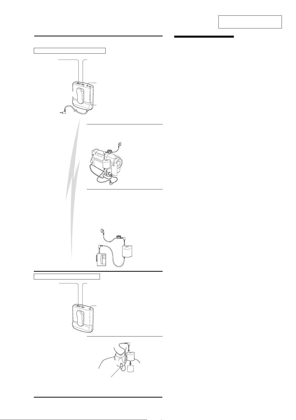
Receiver unit / Récepteur / Empfänger / Ontvanger
4
POWER switch
Interrupteur
d’alimentation (POWER)
Netzschalter POWER
POWER schakelaar
Approx. 45 m (150 feet)
Env. 45 m (150 pieds)
ca. 45 m
Ong. 45 m
1
-a,b
1
-a
3
CHANNEL selector
Sélecteur de canal (CHANNEL)
Wählschalter CHANNEL
CHANNEL keuzeschakelaar
1
-a
To the v (earphone) jack
Vers la prise v (écouteur)
an die Buchse v (Ohrhörer)
Naar v (oortelefoon).
v (earphone) jack
Prise d’écouteur (v)
Ohrhörerbuchse v
v (oortelefoon) aansluiting
MIX MIC jack
Prise de mixage (MIX MIC)
Buchse MIX MIC
MIX MIC aansluiting
earphone (supplied)
écouteur (fourni)
Ohrhörer (mitgeliefert)
oortelefoon (meegeleverd)
To the microphone jack of your
video camera recorder
vers la prise de microphone de
votre camescope
an die Mikrofonbuchse der
Videokamera
Naar de microfoonaansluiting
van uw camcorder
Features
This wireless microphone system is designed to be
used with a video camera recorder, etc. By attaching
the receiver unit onto a video camera recorder, etc.
you can receive the sound picked up by the
transmitter unit. You can enjoy vivid sound which
matches the zoomed up images recorded by your
video camera recorder.
You can also use this system with a tape recorder as a
conventional wireless microphone system to record
the sound.
• The operational distance between the transmitter
unit and the receiver unit can be up to
approximately 45 m (150 feet). However, this
distance may become shorter if there are some
obstacles in between the transmitter unit and the
receiver unit.
• The radio frequency can be selected so that a less
busy channel can be used while the air is busy.
• Compact design featuring built-in antennas.
• The transmitter unit is equipped with a plug in
power∗ type MIC jack (monaural/ 3.5 mm dia.) An
optional microphone other than the supplied one can
be connected to this jack.
• The transmitter and receiver units are equipped with
clip type holders with the adjustable clips which can
be rotated 360 degrees so that the transmitter and
receiver units can be attached onto your clothes, etc.
• The receiver unit is equipped with the MIX MIC jack
to which an optional microphone such as the
ECM-T145 (lavalier microphone) can be connected,
so that the sound transmitted from the transmitter
unit can be mixed with the sound picked up by the
optional microphone.
• The receiver unit is equipped with the v (earphone)
jack to which the supplied earphone can be
connected, so that you can monitor the sound being
recorded. You can use the earphone connected to the
receiver unit to monitor the subject using the
transmitter unit.
• The supplied lavalier microphone has a built-in
wind screen effect so that you can use the
microphone in the open air without a wind screen.
* Plug in power system
The system that power is supplied directly to the
microphone from the microphone jack of the connected
equipment.
1
Transmitter unit / Emetteur / Sender / Zender
4
POWER switch
Interrupteur
d’alimentation (POWER)
Netzschalter POWER
POWER schakelaar
3
2
-b
To the microphone jack of your tape recorder
vers la prise microphone de votre magnétocassette
an die Mikrofonbuchse des Kassettenrecorders
Naar de microfoonaansluiting van uw cassetterecorder
earphone (supplied)
écouteur (fourni)
Ohrhörer (mitgeliefert)
oortelefoon (meegeleverd)
CHANNEL selector
Sélecteur de canal (CHANNEL)
Wählschalter CHANNEL
CHANNEL keuzeschakelaar
2
MIC jack
Prise microphone (MIC)
Buchse MIC
MIC aansluiting
To the v (earphone) jack
Vers la prise v (écouteur)
an die Buchse v (Ohrhörer)
Naar v (oortelefoon).
2
Lavalier microphone (supplied)
Micro-cravate (fourni)
Ansteckmikrofon (mitgeliefert)
Lavalier-microfoon (meegeleverd)
To the MIC jack
vers la prise MIC
an Buchse MIC
Naar de MIC aansluiting
3
WCS-880
)
h
SECTION 2
DISASSEMBLY
Note: Follow the disassembly procedure in the numerical order given.
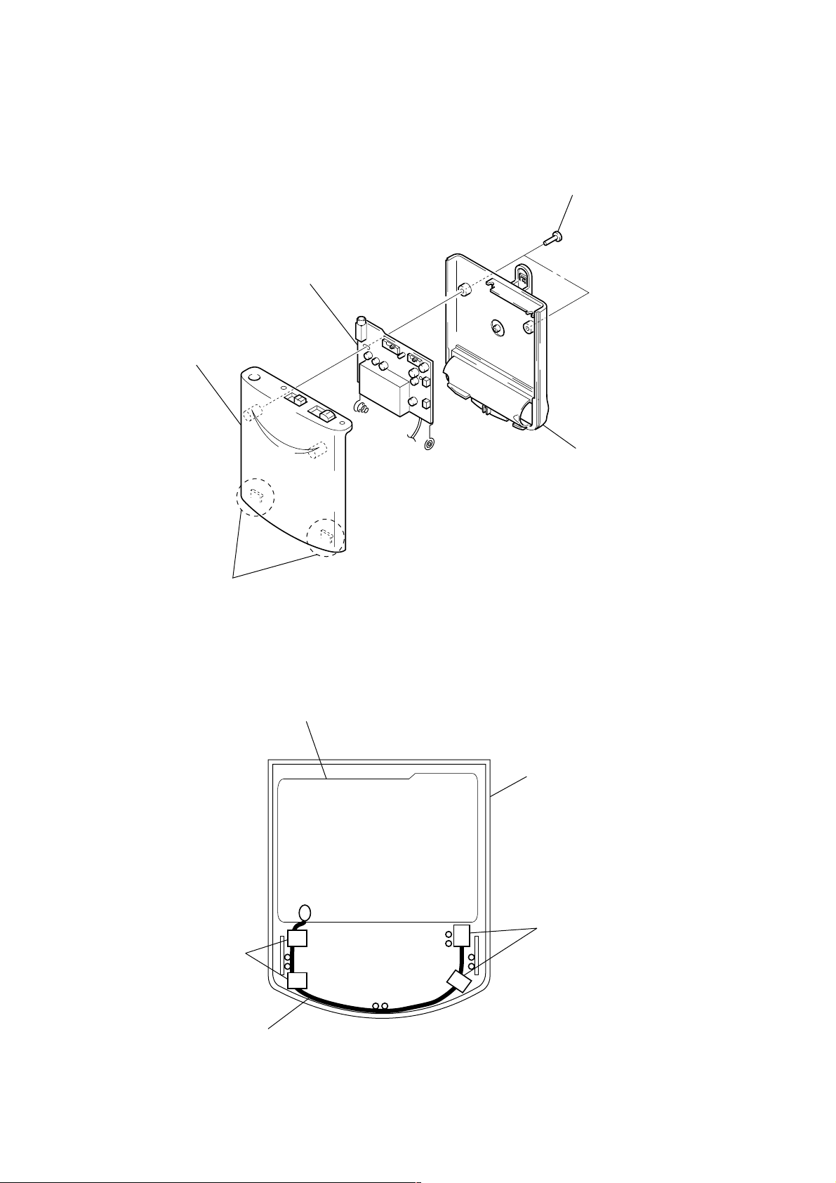
2-1. TX BOARD, VCO BOARD
4
TX board, VCO board
5
case (upper)
1
two screws
(P2
×
6)
2
two claws
2-2. ANTENNA SETTING
TX board
3
case (upper)
case (lower
cushion (lower), switc
cushion (lower), switch
antenna
case (upper) rear view
4
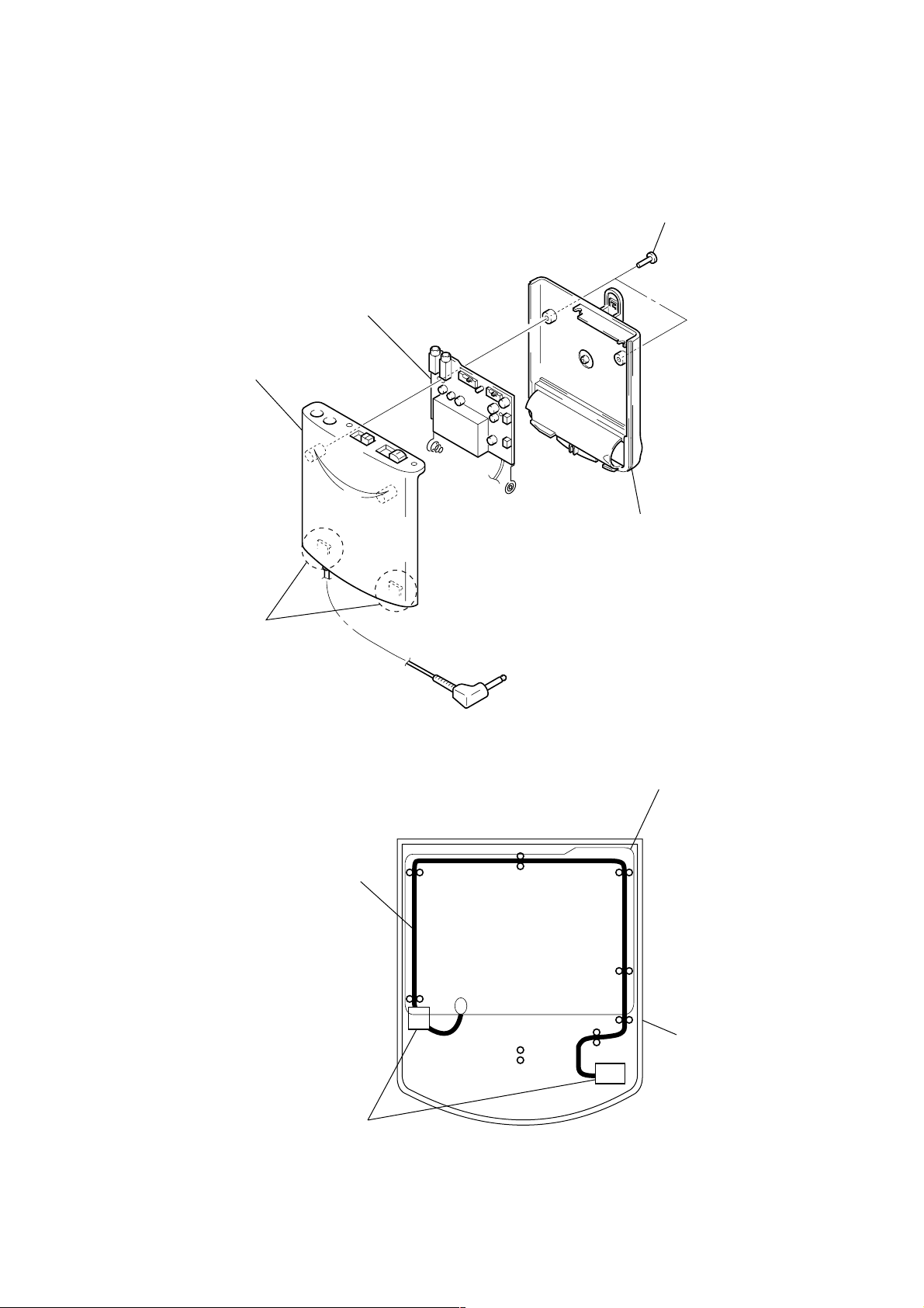
2-3. RX BOARD, FE BOARD
)
)
5
case (upper)
4
RX board, FE board
1
two screws (P2 × 6
WCS-880
2
two claws
2-4. ANTENNA SETTING
antenna
3
case (lower)
RX board
cushion (lower), switch
case (upper
case (upper) rear view
5
WCS-880
r
SECTION 3
ELECTRICAL ADJUSTMENTS
Note: Tool
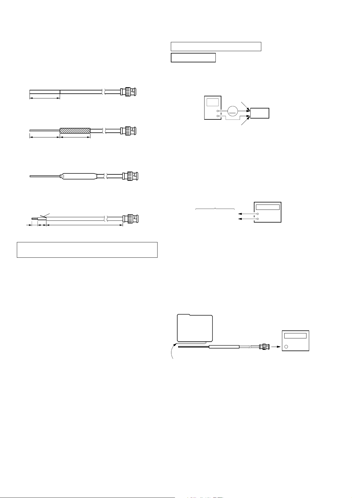
• 1/4 λ sleeve antenna
Production procedure:
1. Cut about 80 mm of the outer cover at the other end of an
approximately 2 meter coaxial cable (1.5D-2V or the equivalent) with a BNC connector.
80 mm
BNC
2. Pull back the outer cover and fold the wire mesh over the outside cover.
80 mm
80 mm
BNC
3. Cover the folded back wire mesh (outer cover) with a tube (for
example, heat shrink tube) and fasten.
BNC
4. Preparation of 1.50 - 2 V coaxial cable
Mesh
4 mm 6 mm
The WCS-880 is a wireless microphone system operating in the 800
MHz. This system comprises the transmitter unit and the receiver unit.
80 cm
BNC
0 dBm = 1 mW, 0 dBV = 1 Vrms
TX SECTION
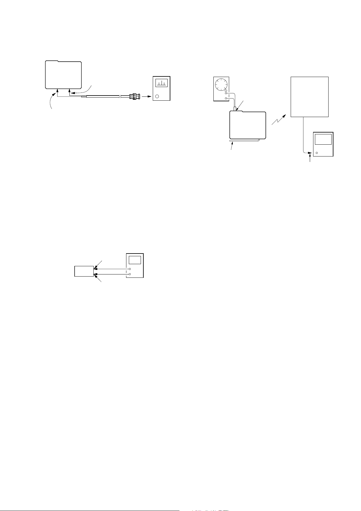
1. Consumption Current Check
Setting:
regulated dc
power supply
+
–
Procedure:
1. Connect a regulated dc po wer supply (1.5 V) and amper e meter.
2. Check that the value of ampere meter satisfy specified value.
Specified value: 50 mA to 60 mA
2. TX OSC (12.8 MHz) Adjustment
Setting:
TX BASE board
Foot of VCO board
shield case
Procedure:
1. Connect a frequency counter to the TP53 on TX BASE board
and the foot of VCO board shield case.
2. Set the [RF CHANNEL] switch (SW51) to[2].
3. Adjust CT2 on the TX BASE board so that the value of
frequency counter becomes 12.794 MHz.
battery
terminal 3
mA
battery
terminal #
TP53
Set
frequency counter
+
–
Specified value: 12.794 ± 0.001 MHz
3. TX Frequency Confirmation
Setting:
TX BASE
board
1/4 λ sleeve antenna
lead wire antenna (ANT1)
frequency counte
Procedure:
1. Connect the 1/4 λ sleeve antenna to a frequency counter, and
put the antenna by the lead wire antenna (ANT1).
2. Set the [RF CHANNEL] switch (SW51) to[1].
3. Confirm that the value of frequency counter satisfy specified
value.
4. Change the [RF CHANNEL] switch (SW51) to [2].
5. Confirm that the value of frequency counter satisfy specified
value.
6. Change the [RF CHANNEL] switch (SW51) to [3].
7. Confirm that the value of frequency counter satisfy specified
value.
Specified values: CH-1: 863.33 MHz to 863.47 MHz
CH-2: 864.13 MHz to 864.27 MHz
CH-3: 864.53 MHz to 864.67 MHz
6
WCS-880
audio
analyzer
AF OSC
Frequency: 1 kHz
Output level: –53.7 dBV
+
–
MIC jack (J1)
TX BASE
board
receiver
unit
lead wire antenna (ANT1)
REC out plug
(P1)
4. TX Output Level Adjustment
Setting:
TX BASE
board
TP54
Foot of VCO board
shield case
spectrum analyzer
more than 1 GHz
Procedure:
1. Solder the core wire of coaxial cable to the CP54 on TX BASE
board, and the mesh to the foot of VCO board shield case.
2. Connect BNC to the spectrum analyzer.
3. Set the [RF CHANNEL] switch (SW51) to [3].
4. Adjust RV51 on the TX B ASE board so that the v alue of spectrum analyzer becomes –1 ± 2.5 dBm.
5. Change the [RF CHANNEL] switch (SW51) to [2].
6. Confirm that the value of spectrum analyzer satisfy specified
value.
7. Change the [RF CHANNEL] switch (SW51) to [1].
8. Confirm that the value of spectrum analyzer satisfy specified
value.
Specified values: CH-1: –1 dBm to ±2.5 dBm
CH-2: –1 dBm to ±2.5 dBm
CH-3: –1 dBm to ±2.5 dBm
5. VCO V oltage Adjustment
Setting:
digital voltmeter
TP58
Set
Foot of VCO board
shield case
+
–
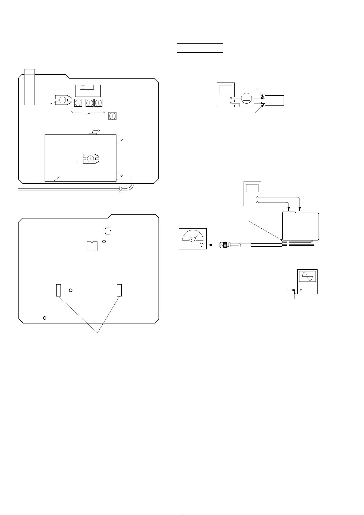
6. TX Modulation Sensitivity Adjustment
Setting:
Procedure:
1. Connect an AF OSC to the MIC jack (J1) on the TX BASE
board (transmitter unit).
2. Connect a 3.3 kΩ load to the REC OUT plug (receiver unit),
and under this condition connect to the audio analyzer.
3. Set the [RF CHANNEL] switch (SW51) to [1].
4. Adjust RV1 on the TX BASE board (transmitter unit) so that
the value of audio analyzer becomes –50 dBV.
5. Change the [RF CHANNEL] switch (SW51) to [2].
6. Adjust RV2 on the TX BASE board (transmitter unit) so that
the value of audio analyzer becomes –50 dBV.
7. Change the [RF CHANNEL] switch (SW51) to [3].
8. Adjust RV3 on the TX BASE board (transmitter unit) so that
the value of audio analyzer becomes –50 dBV.
Adjustment Location: TX BASE Board (See page 8)
Procedure:
1. Connect digital voltmeter to the TP58 on TX BASE board and
2. Set the [RF CHANNEL] switch (SW51) to [3].
3. Adjust CT1 on the VCO board so that the value of digital volt-
4. Set the [RF CHANNEL] switch (SW51) to [1].
5. Confirm that the value of digital voltmeter satisfy specified
6. Set the [RF CHANNEL] switch (SW51) to [2].
7. Confirm that the value of digital voltmeter satisfy specified
Specified values: CH-2: 1.4 V to ±0.1 V
the foot of VCO board shield case.
meter becomes 1.6 V.
value.
value.
CH-1: 1.1 V to ±0.1 V
CH-3: 1.6 V to ±0.1 V
7
WCS-880
+
–
regulated dc
power supply
mA
Set
battery
terminal #
battery
terminal 3
e
Adjustment Location:
MIC jack
(J1)
– TX BASE BOARD –
(Component Side)
SW51
[RF CHANNEL]
CT2
TX OSC (12.8MHz)
Adjustment
Sensitivity Adjustment
–VCO BOARD –
CT1
VCO Voltage
Adjustment
shield case
lead wire antenna (ANT1)
– TX BASE BOARD –
(Conductor Side)
1
t
2 t 3
RV1
TX Modulation
RV2
IC51
RV3
Q50
TX Output Level
TP53
RV51
Adjustment
RX SECTION
1. Consumption Current Check
Setting:
Procedure:
1. Connect a regulated dc power supply (1.5 V) and ampere meter .
2. Set the [RF CHANNEL] switch (SW1) to [1].
3. Check that the value of ampere meter satisfy specified value.
Specified value: 50 mA to 65 mA
2. RX Frequency Adjustment
Setting:
FM RF SSG
Carrier frequency: 863.4 MHz
Modulation: 1 kHz,
Output level: – 60 dBm
antenna (ANT1)
digital voltmeter
lead wire
1/4
antenna
±
20 kHz deviation
+
–
Foot of VCO
board shield
case
λ
sleeve
to TP51
RX BASE
board
oscilloscop
(DC range)
CP54
TP58
Foot of VCO board
shield case
Procedure:
REC out plug (P1)
1. Connect the 1/4 λ sleeve antenna to a SSG, and put the an-
tenna by the lead wire antenna (ANT2).
2. Connect a digital voltmeter to the TP51 on RX B ASE board
and the foot of FE board shield case.
3. Connect REC out plug (P1) to an oscilloscope.
4. Set the [RF CHANNEL] switch (SW1) to [1].
5. Adjust CT1 on the RX BASE board so that the value of digital voltmeter becomes 1.4 V.
6. Confirm that the waveform of oscilloscope is sine wave.
7. Change the carrier frequency of SSG to 864.2 MHz.
8. Change the [RF CHANNEL] switch (SW1) to [2].
9. Adjust CT2 on the RX BASE board so that the value of digital voltmeter becomes 1.4 V.
10. Confirm that the waveform of oscilloscope is sine wave.
11. Change the carrier frequency of SSG to 864.6 MHz.
12. Change the [RF CHANNEL] switch (SW1) to [3].
13. Adjust CT3 on the RX BASE board so that the value of digital voltmeter becomes 1.4 V.
14. Confirm that the waveform of oscilloscope is sine wave.
Adjustment Location: RX BASE Board (See page 9)
8
 Loading...