

Sony VVPL-W385ES User Manual

Video Projector
4-725-441-01 (1)
Operating Instructions
Before operating the unit, please read this manual and supplied Quick
Reference Manual thoroughly and retain them for future reference.
VPL-VW385ES

Table of Contents
Location of Controls
Front/Right Side ................................ 3
Rear/Left Side/Bottom ...................... 4
Remote Control ................................. 5
Connections and
Preparations
Installing the Unit .............................. 6
Adjusting the Picture Position ........... 7
Connecting to Video Equipment or a
Computer ...................................... 12
Projecting
Projecting the Picture ...................... 14
Turning Off the Power ............... 14
Watching 3D Video Images ............. 15
Using the 3D Glasses ................. 15
Using the Picture Position ............... 16
Selecting the Aspect Ratio According to
the Video Signal ........................... 18
Selecting the Picture Viewing
Mode ............................................ 21
Using the Menus
Operation through the Menus .......... 22
Picture Menu ................................... 24
Advanced Picture Menu .................. 30
Screen Menu .................................... 31
Setup Menu ...................................... 33
Function Menu ................................ 35
Items Locked by Settings
Lock ........................................ 37
Installation Menu ............................. 38
Information Menu ............................ 41
About the Preset Memory .......... 41
Using Network Features
Displaying the Control Window of the
Unit with a Web Browser .............42
Operating the Control Window ........43
Switching the Page .....................43
Setting the Access Limitation ....43
Confirming the Information
Regarding the Unit .................. 44
Error Handling
Troubleshooting ...............................45
Warning Indicators ...........................48
Message Lists ...................................49
Others
Updating the Software .....................50
About HDR (high dynamic range) ...50
About the simulated 3D feature ....... 50
NOTICES AND LICENSES FOR
SOFTWARE USED IN THIS
PRODUCT .................................... 50
Replacing the Lamp .........................51
Cleaning ........................................... 54
Specifications ................................... 55
Preset Signals ............................. 56
Input Signals and Adjustable/
Setting Items ........................... 58
Compatible 3D Signals ...............59
3D Signals and Adjustable/Setting
Items ........................................ 59
Aspect Mode .............................. 61
Motionflow ................................. 62
Storage Conditions of Adjustable/
Setting Items ........................... 62
Projection Distance and Lens Shift
Range ............................................ 64
Dimensions ...................................... 68
Index .................................................72
2
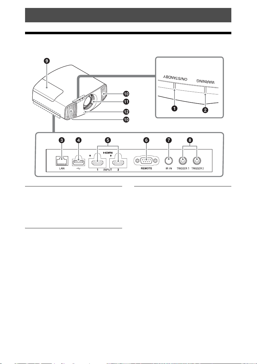
Location of Controls
Front/Right Side
Warning indicators
Warning indicators
a ON/STANDBY indicator
(page 48)
b WARNING indicator (page 48)
Connectors
c LAN connector (page 42)
d USB connector (page 50)
e HDMI 1/HDMI 2 connector
(page 12)
f REMOTE connector
Connects to a computer, etc. for remote
control.
g IR IN connector
Inputs signals to control the unit.
h TRIGGER 1/TRIGGER 2
connector (page 38)
Others
i Lamp cover (page 51)
j Ventilation holes (exhaust)
k Ventilation holes (intake)
(page 53)
l Remote control detector
(page 7)
3
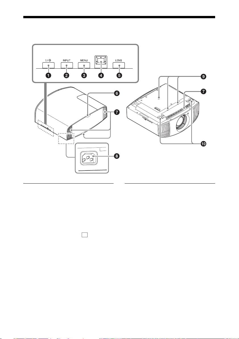
Rear/Left Side/Bottom
The buttons on the control panel have the same names as those on the remote control.
Control panel
Control panel
a ?/1 (ON/STANDBY) button
(page 7)
b INPUT button (page 14)
c MENU button (page 22)
d M/m/</, (arrow)/ (enter)
button (page 22)
e LENS button (page 7)
Others
f Remote control detector
(page 7)
g Ventilation holes (intake)
(page 53)
h AC IN socket (page 7)
i Projector suspension support
attaching hole (page 69)
j Front feet (adjustable) (page 10)
4
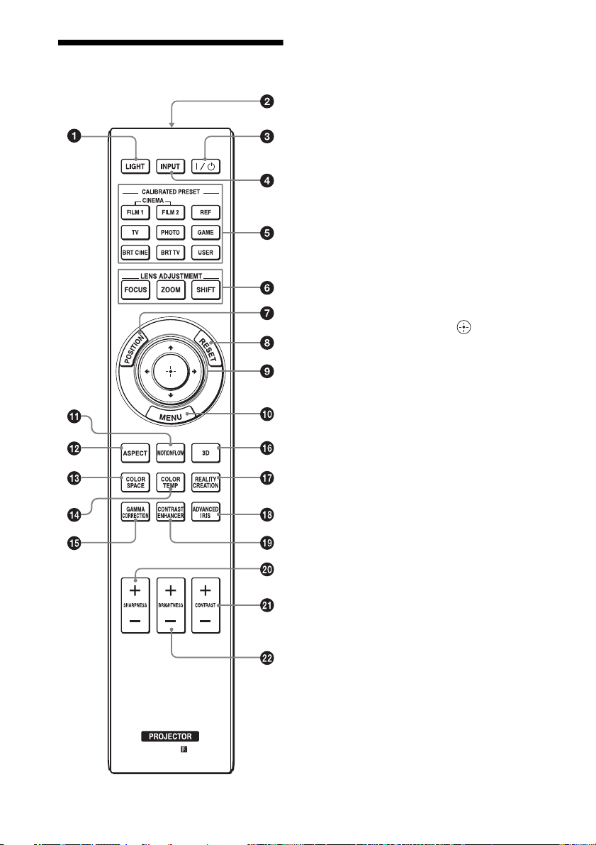
Remote Control
a LIGHT button
Illuminates the buttons on the remote
control.
b Infrared transmitter
c ?/1 (ON/STANDBY) button
(page 7)
d INPUT button (page 14)
e CALIBRATED PRESET buttons
(page 21)
f LENS ADJUSTMENT buttons
(page 8)
g POSITION button (page 16)
h RESET button (page 23)
i M/m/</, (arrow)/ (enter)
buttons (page 22)
j MENU button (page 22)
k MOTIONFLOW button (page 26)
l ASPECT button (page 18)
m COLOR SPACE button (page 29)
n COLOR TEMP button (page 26)
o GAMMA CORRECTION button
(page 27)
p 3D button (page 15)
q REALITY CREATION button
(page 25)
r ADVANCED IRIS button
(page 25)
s CONTRAST ENHANCER button
(page 25)
t SHARPNESS +/– button
(page 27)
u CONTRAST +/– button (page 26)
v BRIGHTNESS +/– button
(page 26)
5
Connections and Preparations
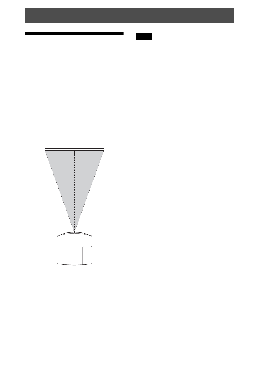
Installing the Unit
The installation distance between the unit
and a screen varies depending on the size of
the screen or whether or not you use the lens
shift features. Install this unit so that it fits
the size of your screen. For details on the
distance between the unit and the screen (the
projection distance) and the size of projected
video, see “Projection Distance and Lens
Shift Range” (page 64).
1 Position the unit so that the lens is
parallel to the screen.
Top view
Screen
Note
When using a screen with an uneven surface,
stripes pattern may rarely appear on the screen
depending on the distance between the screen
and the unit or the zooming magnifications.
This is not a malfunction of the unit.
2 Project an image on the screen and
adjust the picture so that it fits the
screen (page 7).
6
Adjusting the Picture Position
Project an image on the screen and then
adjust the picture position.
Note
Depending on the installation location of the
unit, you may not be able to control it with the
remote control. In this case, point the remote
control at the remote control detector of the
unit or the screen.
1 After connecting the AC power cord to
the unit, plug the AC power cord into
a wall outlet.
The ON/STANDBY indicator lights in
red and the unit goes into standby mode.
Remote control
detector
Tips
?/1 (ON/STANDBY), INPUT, MENU,
• The
and M/m/</,/ (joystick) buttons on
the side panel of the unit function the same as
those on the remote control. The LENS
button functions in the same way as the
LENS ADJUSTMENT (FOCUS, ZOOM,
SHIFT) buttons of the remote control.
• When adjusting the lens, each time you press
the LENS button on the unit, the lens
adjustment function switches between “Lens
Focus,” “Lens Zoom” and “Lens Shift.”
Lights in red.
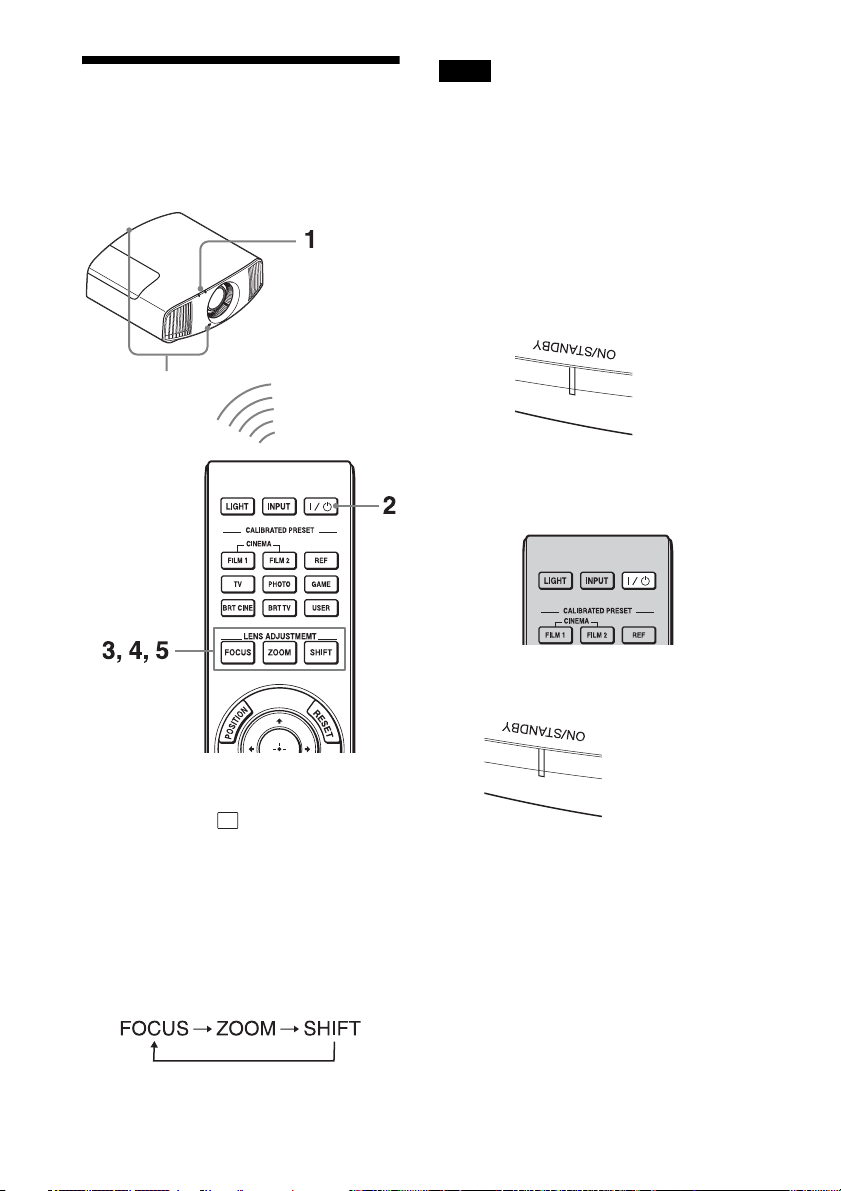
2 Press the ?/1 (ON/STANDBY) button
to turn on the unit.
The ON/STANDBY indicator flashes in
green, and then lights in green.
Flashes in green for
tens of seconds and
then lights in green.
7
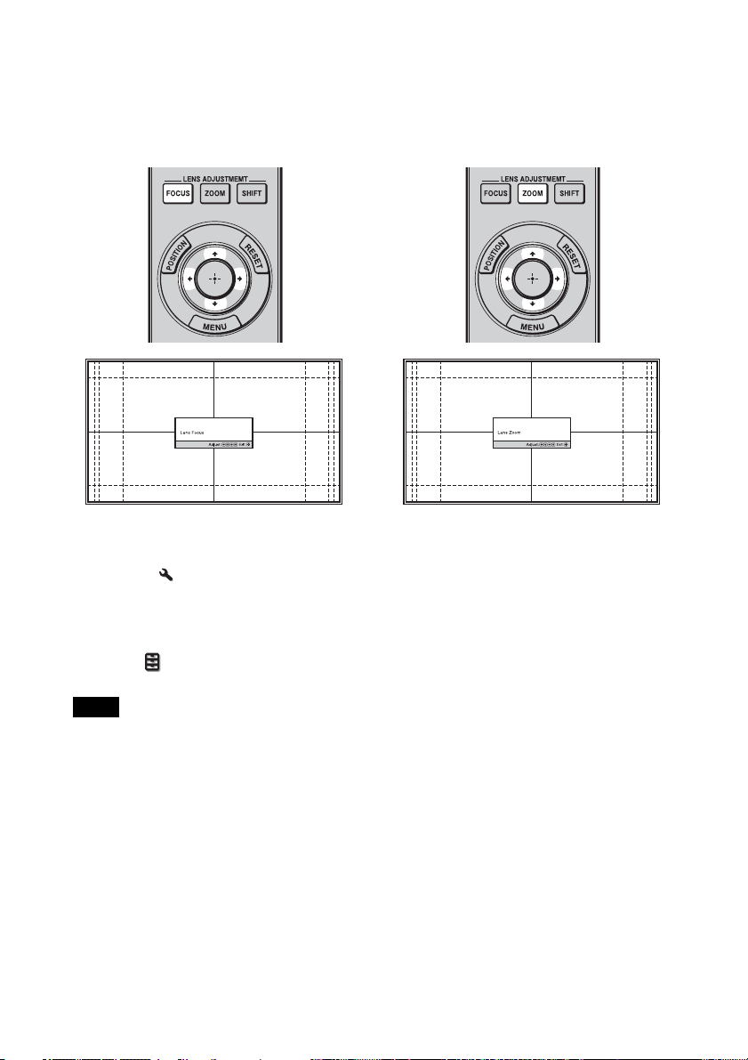
3 Adjust the focus.
Press the LENS ADJUSTMENT
(FOCUS) button to display the Lens
Focus adjustment window (test pattern).
Then adjust the focus of the picture by
pressing the M/m/</, buttons.
4 Adjust the picture size.
Press the LENS ADJUSTMENT
(ZOOM) button to display the Lens
Zoom adjustment window (test pattern).
Then adjust the size of the picture by
pressing the M/m/</, buttons.
Tips
• When “Lens Control” is set to “Off” on the
Installation menu, you cannot adjust the
focus, the picture size or the proper position
by pressing the FOCUS, ZOOM or SHIFT
buttons (page 38).
• When “Test Pattern” is set to “Off” on the
Function menu, the test pattern is not
displayed (page 36).
Note
Adjust the lens by using buttons on the remote
control or the control panel of the unit. Never
make adjustments by directly turning the lens
with your hands, which may cause damage or
malfunction to the unit.
To make the picture larger, press M/,.
To make the picture smaller, press m/
<.
8
5 Adjust the picture position.
Press the LENS ADJUSTMENT
(SHIFT) button to display the Lens Shift
adjustment window (test pattern). Then
adjust to the proper position of the
picture by pressing the M/m/</,
buttons.
Tip
Whenever you press the button, the test
pattern disappears.
Note
When adjusting the window position, do not
touch the lens unit, otherwise your fingers may
be pinched by the moving parts.
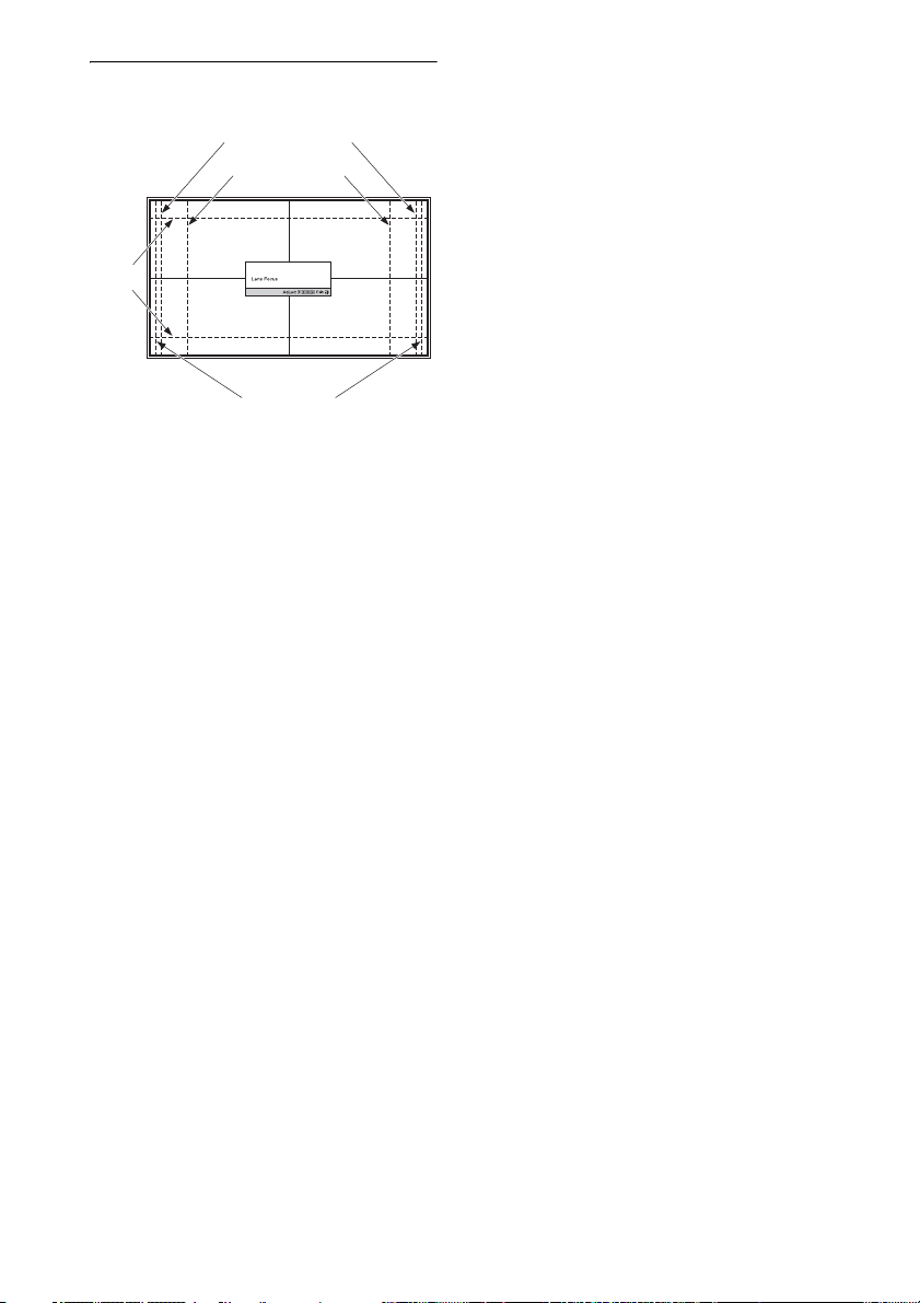
To adjust the horizontal position
Press </,.
The picture projected on the screen moves
right or left by a maximum of 31% of the
screen width from the center of the lens.
Top view
31% 31%1 screen width
: Picture position when moving the
picture to the left at maximum
: Picture position when moving the
picture to the right at maximum
Press the RESET button on the remote
control while the Lens Shift adjustment
window is displayed, the horizontal position
returns to the center of the lens (factory
default position). The zoom and focus are
not changed.
9
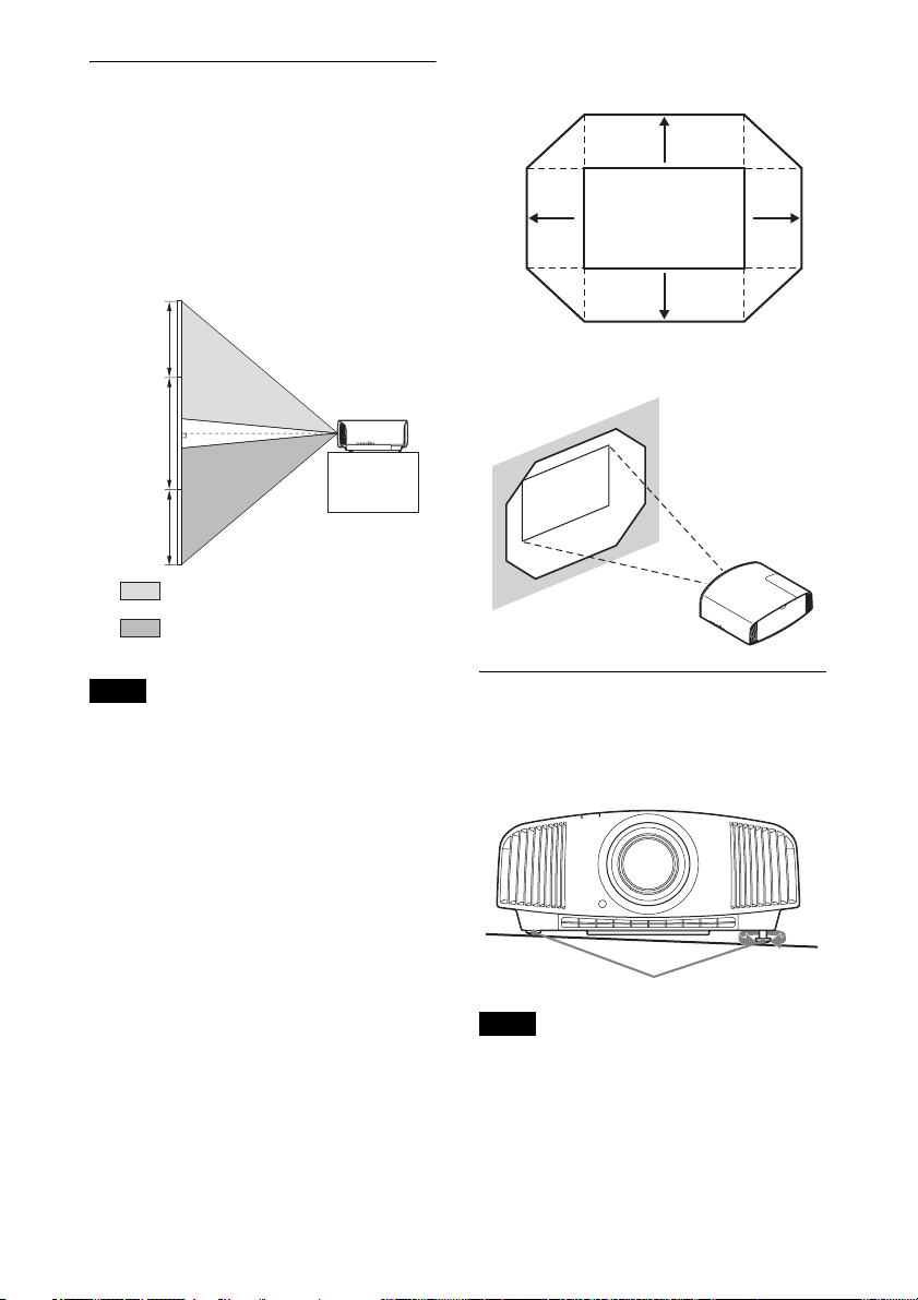
To adjust the vertical position
Press M/m.
The picture projected on the screen moves
up by a maximum of 85% or moves down by
a maximum of 80% of the screen height
from the center of the lens.
Side view
Range of movement of the projected
picture
0.85V
0.31H
Projected Picture
0.8V
0.31H
85%
1 screen
height
80%
: Picture position when moving the
picture upward at maximum
: Picture position when moving the
picture downward at maximum
Note
The range to move the picture projected on the
screen can be adjusted only within the octagon
area illustrated below. For details, see
“Projection Distance and Lens Shift Range”
(page 64).
H: Width of the projected picture
V: Height of the projected picture
To adjust the tilt of the installation
surface
If the unit is installed on an uneven surface,
use the front feet (adjustable) to keep the unit
level.
Turn to
Front feet (adjustable)
Notes
adjust.
• If the unit is tilted up or down, the projected
image may be trapezoidal.
• Be careful not to catch your finger when
turning the front feet (adjustable).
10
Lens adjustment window (test
pattern)
1.78:1 (16:9)
1.33:1 (4:3)
2.35:1
1.85:1
The dashed lines show the screen sizes of each
aspect ratio.
11
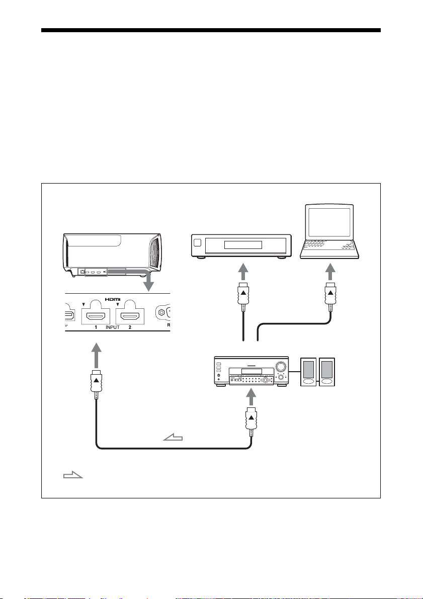
Connecting to Video Equipment or a Computer
You can enjoy high picture quality by connecting a DVD player/recorder, Blu-ray Disc player/
recorder, or PlayStation
®
equipped with HDMI output to the HDMI input of the unit.
When making connections, be sure to do the following:
• Turn off all equipment before making any connections.
• Use the proper cables for each connection.
• Insert the cable plugs properly; poor connection at the plugs may cause a malfunction or poor
picture quality. When pulling out a cable, be sure to pull it out from the plug, not the cable
itself.
• Refer to the operating instructions of the connected equipment.
Computer
Right side of the unit
Equipment with HDMI
output connectors
AV amplifier
Speakers
to HDMI output
HDMI cable (not supplied)
: Video signal flow Use a High Speed HDMI cable or a Premium High Speed
HDMI cable on which the cable type logo is specified.
12

Notes
• Use a High Speed HDMI cable or a Premium High Speed HDMI cable. With a standard HDMI
cable, images of 1080p, DeepColor, 3D video and 4K video may not be displayed properly.
• When connecting an HDMI cable to the unit, make sure the
V mark on the upper part of the HDMI
input of the unit and the v mark on the connector of the cable is set at the same position.
• If the picture from equipment connected to the unit with an HDMI cable is not correct, check the
settings of the connected equipment.
• If you set your computer, such as a notebook type, to output the signal to both computer’s display
and this equipment, the picture of the equipment may not appear properly. Set your computer to
output the signal to only the external monitor. For details, refer to the computer’s operating
instructions supplied with your computer. For settings of the computer, consult with the
manufacturer of the computer.
13
Projecting
Projecting the Picture
1 Turn on both the unit and the
equipment connected to the unit.
2 Press INPUT to display the input
palette on the screen.
3 Select the equipment from which you
want to display images.
Press INPUT repeatedly or press M/m/
(enter) to select the equipment from
which to project.
The fan stops and the ON/STANDBY
indicator changes from flashing green to
remaining red.
The power is turned off completely, and you
can disconnect the AC power cord.
Note
Never disconnect the AC power cord while the
indicator is flashing.
Tip
You can turn off the unit by holding the ?/1
(ON/STANDBY) button for about 1 second,
instead of performing the above steps.
Example: To view the picture from the
video equipment connected to the HDMI
1 connector of this unit.
Tip
When “Status” is set to “Off” on the Setup
menu, the input palette does not appear. Press
the INPUT button to switch between input
terminals in sequence.
Turning Off the Power
1 Press the ?/1 (ON/STANDBY)
button.
A message “POWER OFF?” appears on
the screen.
2 Press the ?/1 (ON/STANDBY) button
again before the message disappears.
The ON/STANDBY indicator flashes in
green and the fan continues to run to
reduce the internal heat.
14

Watching 3D Video Images
You can enjoy powerful 3D video images,
such as from 3D games and 3D Blu-ray
Discs, using the optional Active 3D Glasses
(TDG-BT500A).
Adjusting/Setting the 3D functions
You can adjust/set the 3D functions by
pressing the 3D button on the remote control
or with the “3D Settings” of the Function
menu. For details, see “3D Settings”
(page 35).
Using the 3D Glasses
1 Turn on the HDMI equipment for 3D
compatibility connected to the unit,
then play the 3D content.
For details on how to play 3D content,
refer to the operating instructions for the
connected equipment.
2 Turn on the unit and project the 3D
video image onto the screen.
For details on how to project the image,
see “Projecting the Picture” (page 14).
3 Turn on the 3D glasses, and then put
them on so that they fit comfortably.
For details on how to use the 3D glasses,
see “Using the 3D Glasses” (page 15).
Tips
• The factory default setting for ”2D-3D
Display Sel.” is “Auto” to allow projecting
3D video images automatically when the unit
detects 3D signals.
• To convert 3D video images to 2D video
images, set “2D-3D Display Sel.” to “2D”
(page 35).
Notes
• It may not be possible to display 3D video
image, depending on the type of signal. Set
the “2D-3D Display Sel.” to “3D,” and “3D
Format” to “Side-by-Side” or “Over-Under”
to suit the format of the 3D content you want
to watch (page 35).
• Use the 3D glasses within the
communication range (page 15).
• There are differences in perception of 3D
video images among individuals.
• When the temperature of the usage
environment is low, the 3D effect may be
diminished.
1 Turn on the 3D glasses, and register
them on the unit.
For details on how to register the 3D
glasses, refer to the operating
instructions supplied with the 3D
glasses.
2 Put on the 3D glasses.
3 Turn toward the screen.
Precautions for use
Misoperation may occur if:
• The viewing position is too far from the
projector
• There are other communication devices,
such as a wireless LAN (IEEE802.11 b/g/
n) or a microwave with a bandwidth of 2.4
GHz, near the unit
3D glasses communication range
Figure below indicate the communication
range of the 3D glasses. If you try to watch
3D video images from a distance greater
than the communication range or install the
unit outside the communication range, the
3D glasses may not be able to display the
images properly. Also, the distance varies
depending on the environment of the room
and installation environment of the unit.
15
Top or side view
Projector
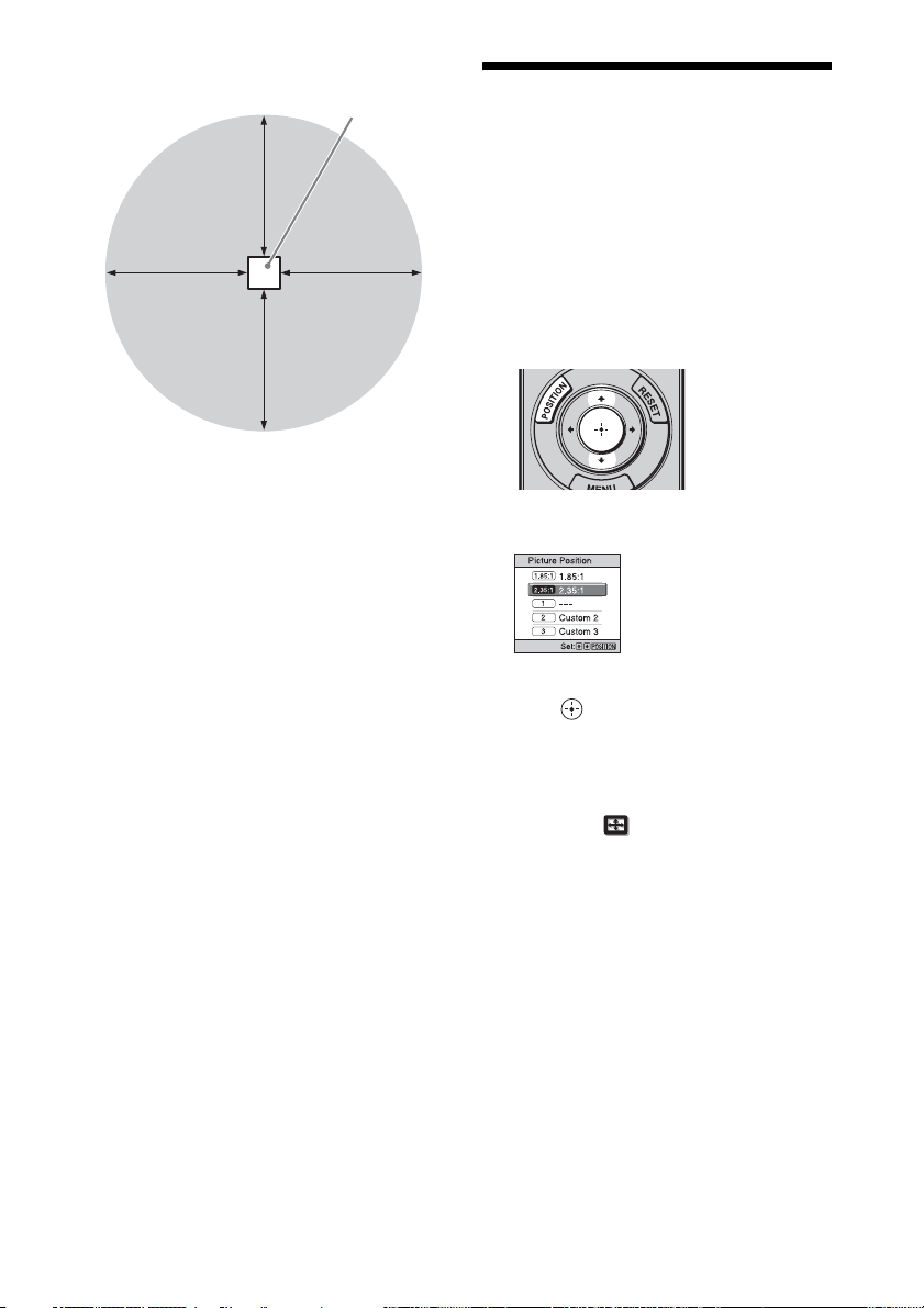
Using the Picture Position
10 m
10 m
You can store up to five combinations of lens
settings (focus, picture size, picture
position), aspect ratio, and blanking. These
10 m 10 m
settings can be recalled.
In the factory preset setting, the Picture
Position is not stored.
1 Press POSITION.
The Picture Position selecting palette is
displayed.
2 Press POSITION repeatedly, or press
M/m/ to select the position.
The settings of the position selected is
recalled.
Store or delete lens settings, aspect ratio,
and blanking in the “Picture Position” of
the Screen menu (page 31).
The position where the lens settings,
aspect ratio, and blanking are not stored
is displayed as “---.”
16
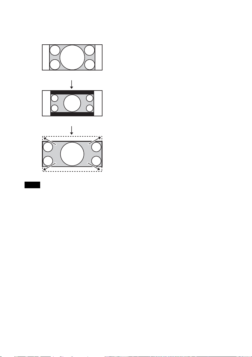
Image of the lens moving
In the example below, the images with
aspect ratio of 1.78:1 (16:9) and 2.35:1 are
projected on a 2.35:1 screen.
When a 1.78:1 (16:9) image is input
When a 2.35:1 image is input
Press the POSITION
button.
The 2.35:1 image expands to fill the screen.
Notes
• After you have selected and confirmed the
lens position, the lens starts to move. Do not
touch, or place anything near, the lens,
otherwise it may cause injury or a
malfunction.
• If you press any button on the remote control
or the unit while the lens is moving, the lens
stops. In this case, select the lens position
again or adjust the lens manually.
• The Picture Position function is not
guaranteed to reproduce the lens settings
precisely.
• When you use the subtended screen angle of
two or more aspects using lens zoom, install
the unit within the specified parameters
referring to “Projection distance” (page 65).
With some setting positions, the range of lens
shift may be restricted, even though the unit
is installed within the specified parameters.
17
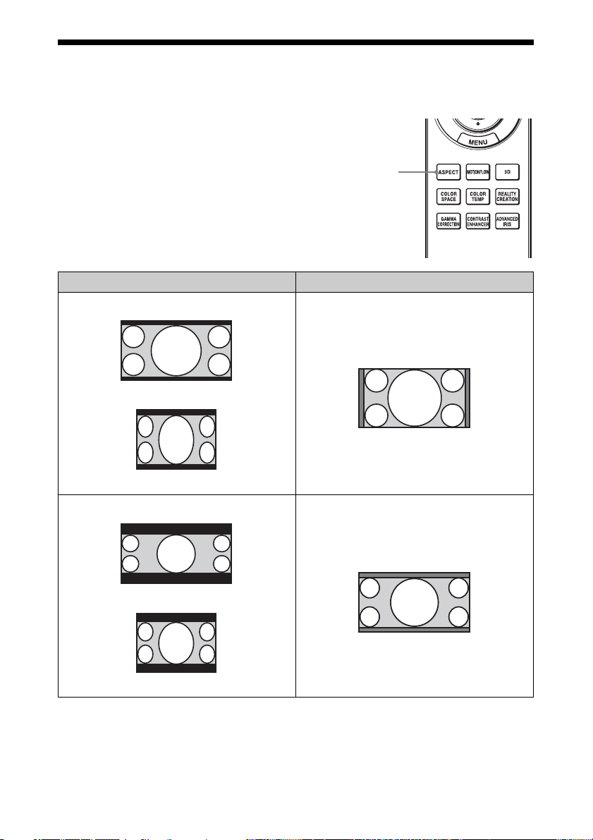
Selecting the Aspect Ratio According to the Video Signal
You can select an aspect ratio best suited for
the video signal received.
Press ASPECT.
Each time you press the button, you can
select the “Aspect” setting.You can also
select it using the menu (page 32).
Original image Recommended setting and resultant images
1.85:1
Squeezed 1.85:1
ASPECT
button
1.85:1 Zoom
2.35:1 Zoom
2.35:1
Squeezed 2.35:1
18
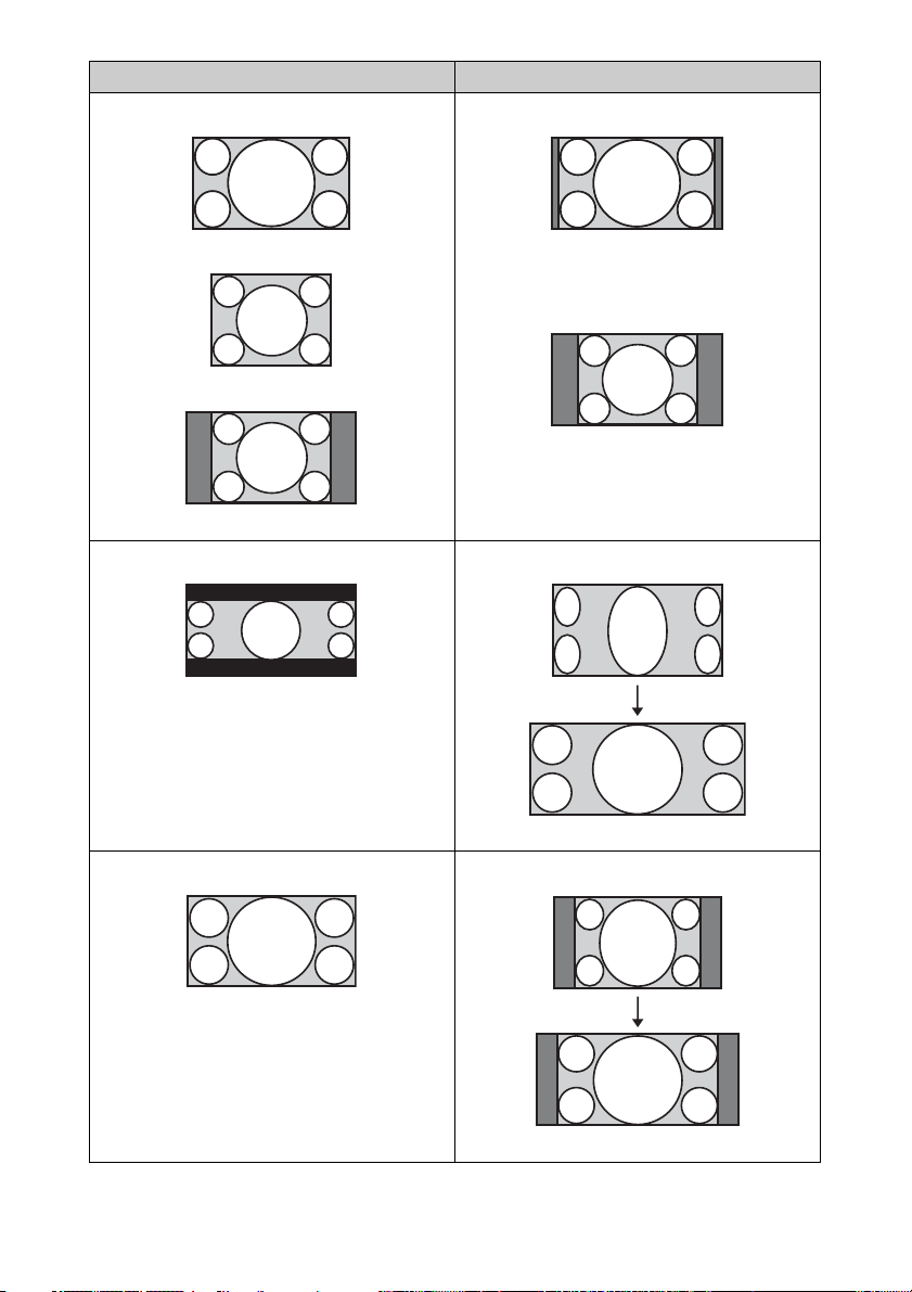
Original image Recommended setting and resultant images
Normal
1.78:1 (16:9)
1.33:1 (4:3)
1.33:1 (4:3) with side panels
V Stretch
2.35:1
16:9
When using an anamorphic lens
Squeeze
When using an anamorphic lens
19
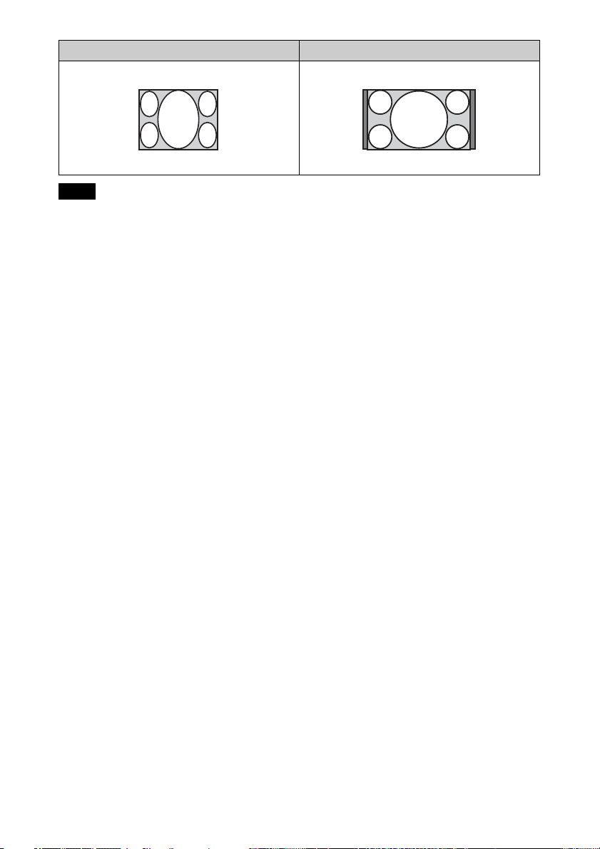
Original image Recommended setting and resultant images
Stretch
Squeezed
Notes
• Selectable aspect modes vary depending on
the input signal (page 61).
• The aspect cannot be selected for an input
signal from a computer, or an input signal
with a resolution of 4096 × 2160 (page 56).
Notes on switching the “Aspect”
setting
• Select the aspect mode taking into account
that changing the aspect ratio of the
original picture will provide a different
look from that of the original image.
• Note that if the unit is used for profit or for
public viewing, modifying the original
picture by switching the aspect may
constitute an infringement of the rights of
authors or producers, which are legally
protected.
20
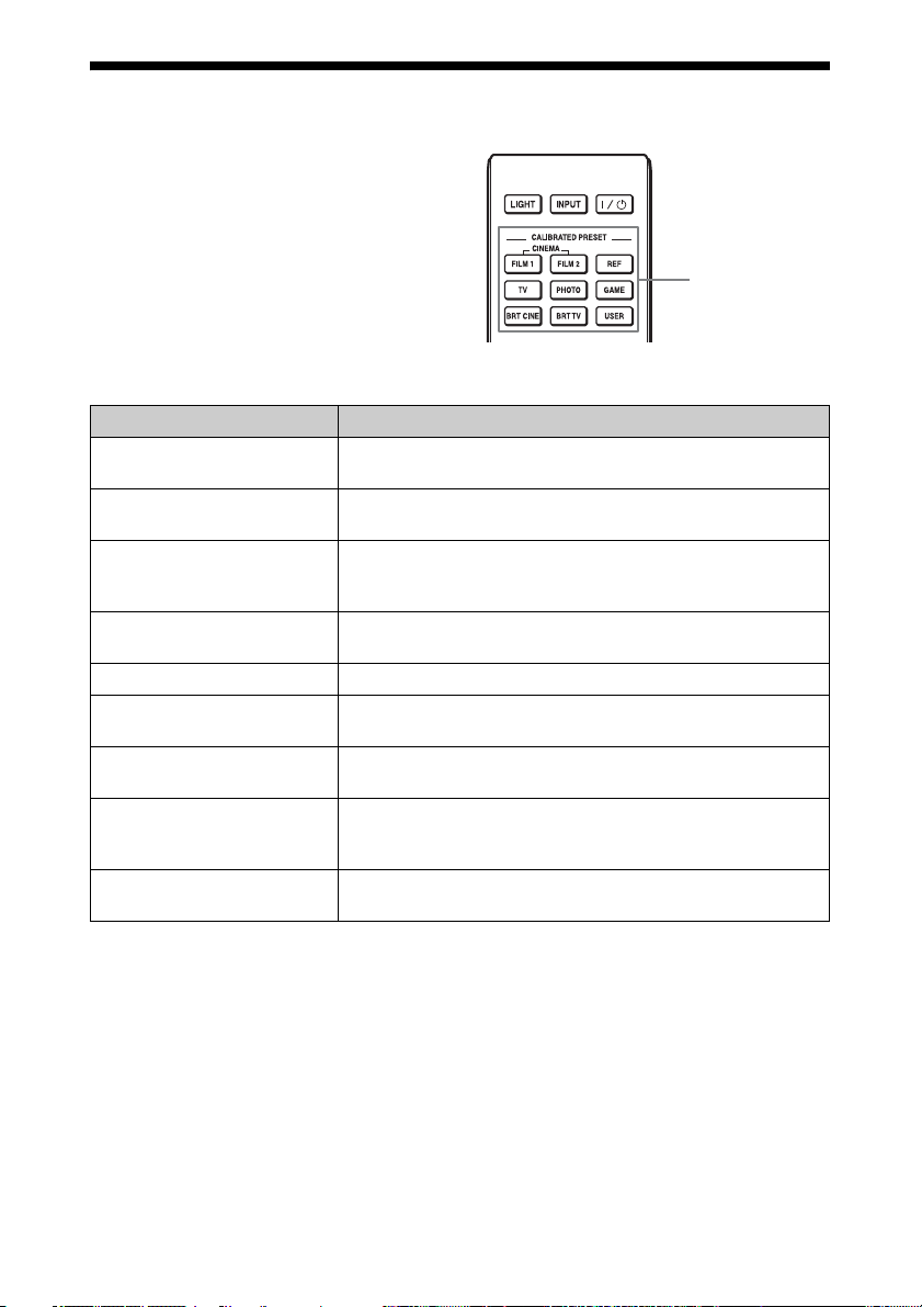
Selecting the Picture Viewing Mode
You can select the picture viewing mode that
best suits the type of video source or room
conditions.
You can save and use different preset modes
for 2D/3D respectively.
Press one of the CALIBRATED PRESET
buttons.
Setting items Description
CINEMA FILM 1 Picture quality suited to reproducing the highly dynamic and
clear images typical of master positive film.
CINEMA FILM 2 Picture quality suited to reproducing the rich tone and color
typical of a movie theater, based on the Cinema Film 1.
REF A picture quality setup suitable for when you want to reproduce
faithfully the original image quality, or for enjoying image
quality, without any adjustment.
TV Picture quality suited for watching TV programs, sports,
concerts, and other video images.
PHOTO Ideal for projecting still images taken with a digital camera.
GAME Picture quality suited to gaming, with well-modulated colors
and fast response.
BRT CINE Picture quality suited for watching movies in a bright
environment, such as a living room.
BRT TV Picture quality suited for watching TV programs, sports,
concerts, and other video images in a bright environment, such
as a living room.
USER Adjusts the picture quality to suit your taste then saves the
setting. The factory default setting is the same as “REF.”
CALIBRATED
PRESET buttons
21
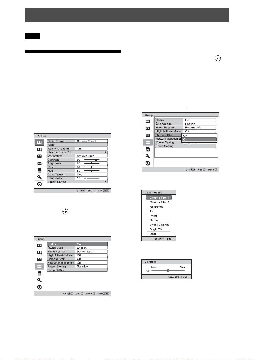
Using the Menus
Note
The menu displays used for the explanation may be different from the actual menu display.
3 Press M/m to select an item you want
Operation through the Menus
The unit is equipped with an on-screen menu
for making various adjustments and settings.
If you select an item name followed by an
arrow (B), the next menu window with
setting items appears.
1 Press MENU.
The menu window appears.
to set or adjust and press , or .
The setting items are displayed in a popup menu, in a setting menu, in an
adjustment menu or in the next menu
window.
Pop-up menu
Setting items
Setting menu
2 Press M/m to select a menu item, and
press , or .
The items that can be set or adjusted
with the selected menu appear. The item
presently selected is shown in white.
Adjustment menu
22
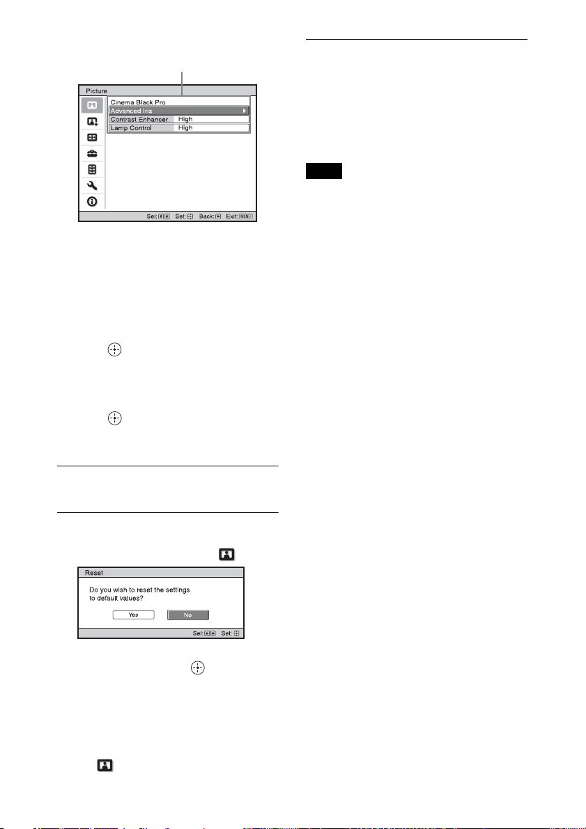
Next menu window
Setting items
4 Make the setting or adjustment of an
item.
When changing the adjustment
level
Press M/, to increase the value, and
press m/< to decrease the value.
Press to store the setting and restore
the original menu screen.
When changing the setting
Press M/m to change the setting.
Press to restore the original screen.
You can restore the original screen using
< depending on the selected item.
To reset the items that have been
adjusted
Select an item in the menu screen, and
display the pop-up menu, the setting menu,
or the adjustment menu.
Press RESET on the remote control to reset
only the selected settings to its factory preset
value.
Note
The RESET button on the remote control is
available only when the adjustment menu or
the setting menu is selected.
To clear the menu
Press MENU.
To reset the picture that has been
adjusted
Select “Reset” from the Picture menu.
When the screen display appears, select
“Yes” using < and press .
All of the following settings are reset to its
factory preset value:
“Reality Creation,” “Cinema Black Pro,”
“Motionflow,” “Contrast,” “Brightness,”
“Color,” “Hue,” “Color Temp.,”
“Sharpness,” and “Expert Setting” on the
Picture menu
23
 Loading...