

Sony VSX AX5I Service Manual
PIONEER CORPORATION 4-1, Meguro 1-chome, Meguro-ku, Tokyo 153-8654, Japan
PIONEER ELECTRONICS (USA) INC. P.O. Box 1760, Long Beach, CA 90801-1760, U.S.A.
PIONEER EUROPE NV Haven 1087, Keetberglaan 1, 9120 Melsele, Belgium
PIONEER ELECTRONICS ASIACENTRE PTE. LTD. 253 Alexandra Road, #04-01, Singapore 159936
PIONEER CORPORATION 2003
ORDER NO.
RRV2801
VSX-AX5i-S
AUDIO/VIDEO MULTI-CHANNEL RECEIVER
VSX-AX5i-S
VSX-AX3-S
VSX-AX3-K
THIS MANUAL IS APPLICABLE TO THE FOLLOWING MODEL(S) AND TYPE(S).
Model Type Power Requirement
VSX-AX5i-S HYXJI AC220-230V AC240V, *
VSX-AX3-S HYXJI AC220-230V AC240V, *
VSX-AX3-K HYXJI AC220-230V AC240V, *
*:Alter the wiring of the power-supply block at the primary winding of Power transformer referring to the Line Voltage Selection
described in Service Manual.
The voltage can be converted by the
following method.
For details, refer to "Important symbols for good services".
T-ZZE JULY 2003 printed in Japan
1234
SAFTY INFORMATION
A
This service manual is intended for qualified service technicians; it is not meant for the casual
do-it-yourselfer. Qualified technicians have the necessary test equipment and tools, and have been
trained to properly and safely repair complex products such as those covered by this manual.
Improperly performed repairs can adversely affect the safety and reliability of the product and may
void the warranty. If you are not qualified to perform the repair of this product properly and safely, you
should not risk trying to do so and refer the repair to a qualified service technician.
WARNING
B
This product contains lead in solder and certain electrical parts contain chemicals which are known to the state of California to
cause cancer, birth defects or other reproductive harm.
Health & Safety Code Section 25249.6 – Proposition 65
NOTICE
(FOR CANADIAN MODEL ONLY)
Fuse symbols (fast operating fuse) and/or (slow operating fuse) on PCB indicate that replacement
parts must be of identical designation.
REMARQUE
(POUR MODÈLE CANADIEN SEULEMENT)
C
Les symboles de fusible (fusible de type rapide) et/ou (fusible de type lent) sur CCI indiquent que
les pièces de remplacement doivent avoir la même désignation.
(FOR USA MODEL ONLY)
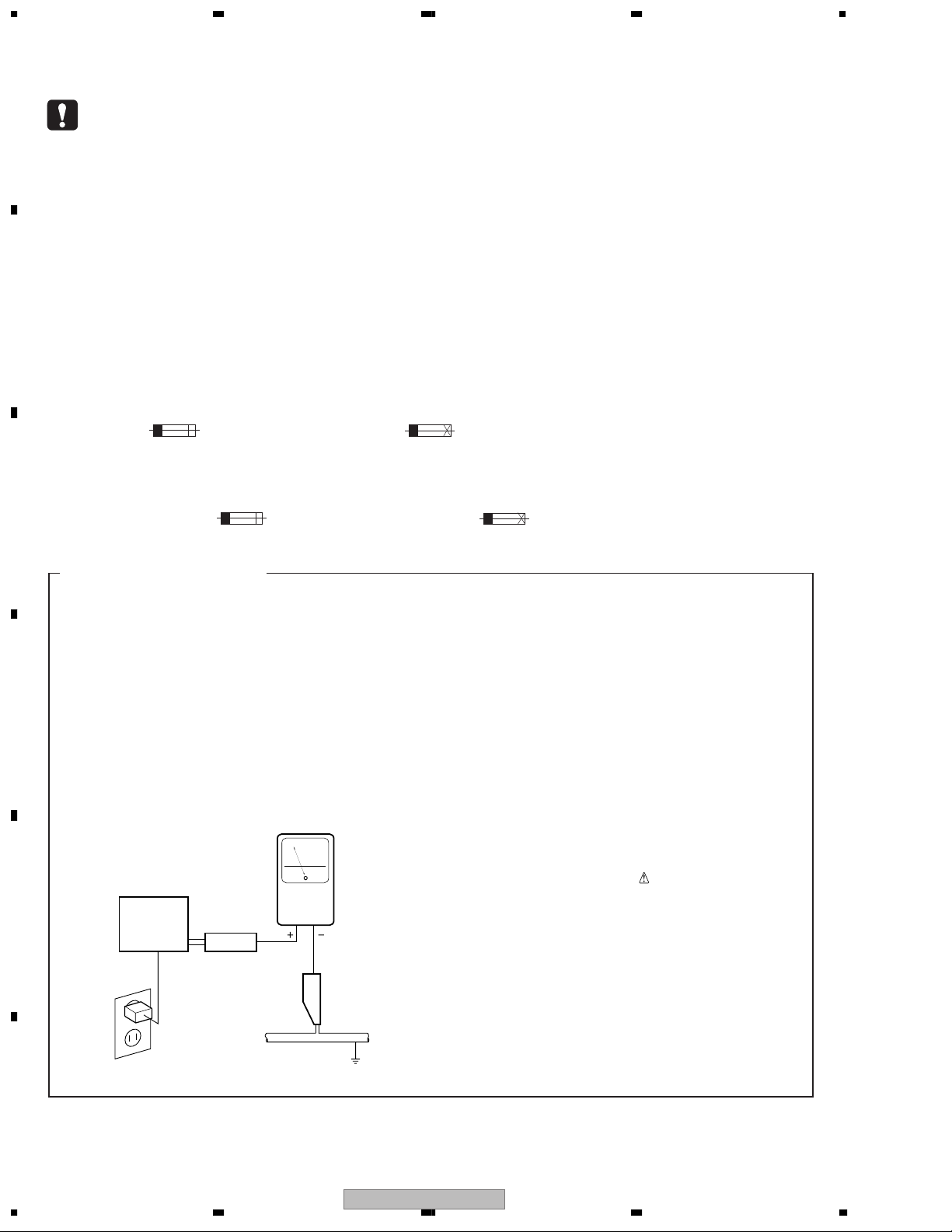
1. SAFETY PRECAUTIONS
The following check should be performed for the
continued protection of the customer and service
technician.
LEAKAGE CURRENT CHECK
Measure leakage current to a known earth ground
(water pipe, conduit, etc.) by connecting a leakage
D
E
current tester such as Simpson Model 229-2 or
equivalent between the earth ground and all exposed
metal parts of the appliance (input/output terminals,
screwheads, metal overlays, control shaft, etc.). Plug
the AC line cord of the appliance directly into a 120V
AC 60 Hz outlet and turn the AC power switch on. Any
current measured must not exceed 0.5 mA.
Reading should
not be above
0.5 mA
Earth
ground
Device
under
test
Also test with
plug reversed
(Using AC adapter
plug as required)
Test all
exposed metal
surfaces
Leakage
current
tester
AC Leakage Test
ANY MEASUREMENTS NOT WITHIN THE
LIMITS OUTLINED ABOVE ARE INDICATIVE
OF A POTENTIAL SHOCK HAZARD AND
MUST BE CORRECTED BEFORE RETURNING THE APPLIANCE TO THE CUSTOMER.
2. PRODUCT SAFETY NOTICE
Many electrical and mechanical parts in the appliance
have special safety related characteristics. These are
often not evident from visual inspection nor the
protection afforded by them necessarily can be obtained
by using replacement components rated for voltage,
wattage, etc. Replacement parts which have these
special safety characteristics are identified in this
Service Manual.
Electrical components having such features are
identified by marking with a
on the parts list in this Service Manual.
The use of a substitute replacement component which
does not have the same safety characteristics as the
PIONEER recommended replacement one, shown in the
parts list in this Service Manual, may create shock, fire,
or other hazards.
Product Safety is continuously under review and new
instructions are issued from time to time. For the latest
information, always consult the current PIONEER
Service Manual. A subscription to, or additional copies
of, PIONEER Service Manual may be obtained at a
nominal charge from PIONEER.
on the schematics and
F
2
1234
VSX-AX5i-S
5 678
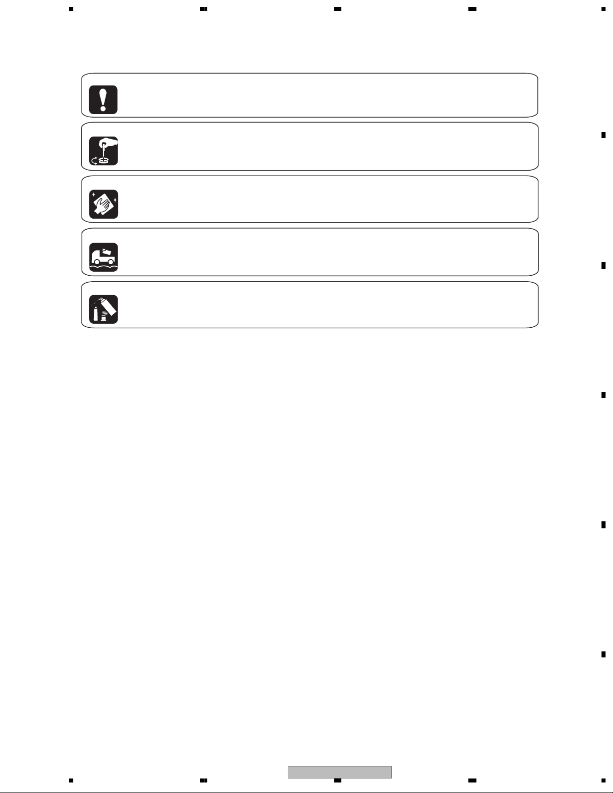
[ Important symbols for good services ]
In this manual, the symbols shown-below indicate that adjustments, settings or cleaning should be made securely.
When you find the procedures bearing any of the symbols, be sure to fulfill them:
1. Product safety
You should conform to the regulations governing the product (safety, radio and noise, and other regulations), and
should keep the safety during servicing by following the safety instructions described in this manual.
2. Adjustments
To keep the original performances of the product, optimum adjustments or specification confirmation is indispensable.
In accordance with the procedures or instructions described in this manual, adjustments should be performed.
3. Cleaning
For optical pickups, tape-deck heads, lenses and mirrors used in projection monitors, and other parts requiring cleaning,
proper cleaning should be performed to restore their performances.
4. Shipping mode and shipping screws
To protect the product from damages or failures that may be caused during transit, the shipping mode should be set or
the shipping screws should be installed before shipping out in accordance with this manual, if necessary.
A
B
5. Lubricants, glues, and replacement parts
Appropriately applying grease or glue can maintain the product performances. But improper lubrication or applying
glue may lead to failures or troubles in the product. By following the instructions in this manual, be sure to apply the
prescribed grease or glue to proper portions by the appropriate amount.For replacement parts or tools, the prescribed
ones should be used.
CONTENTS
SAFTY INFORMATION ........................................................................................................................................2
1. SPECIFICATIONS.............................................................................................................................................5
2. EXPLODED VIEWS AND PARTS LIST.............................................................................................................8
2.1 PACKING ....................................................................................................................................................8
2.2 EXTERIOR SECTION ..............................................................................................................................10
2.3 REAR PANEL SECTION ..........................................................................................................................12
2.4 HEAT SINK SECTION ..............................................................................................................................14
2.5 FRONT PANEL SECTION ........................................................................................................................16
3. BLOCK DIAGRAM AND SCHEMATIC DIAGRAM ..........................................................................................18
3.1 BLOCK DIAGRAM....................................................................................................................................18
3.1.1 AUDIO BLOCK DIAGRAM.....................................................................................................................18
3.1.2 DSP BLOCK DIAGRAM ........................................................................................................................20
3.1.3 1394 BLOCK DIAGRAM........................................................................................................................22
3.1.4 POWER AMP BLOCK DIAGRAM..........................................................................................................23
3.1.5 VIDEO BLOCK DIAGRAM.....................................................................................................................24
3.2 OVERALL WIRING DIAGRAM .................................................................................................................26
3.3 7.1 CH I/O, V-AUDIO, FRONT IN and OPTICAL IN ASSYS.....................................................................28
3.4 INPUT CONNECT ASSY..........................................................................................................................30
3.5 COAXIAL IN ASSY...................................................................................................................................32
3.6 COMPONENT ASSY................................................................................................................................34
3.7 VIDEO ASSY ............................................................................................................................................36
3.8 MAIN CONTROL ASSY (1/3) ...................................................................................................................38
3.9 MAIN CONTROL ASSY (2/3) ...................................................................................................................40
3.10 MAIN CONTROL ASSY (3/3) .................................................................................................................42
3.11 MIC & F.OPT IN, MIC AMP and DSP CONNECTION ASSYS ...............................................................44
3.12 POWER AMP IN, FAN CONNECTION and FAN DRIVE ASSYS...........................................................46
3.13 DSP ASSY (1/2) .....................................................................................................................................48
3.14 DSP ASSY (2/2) .....................................................................................................................................50
3.15 1394 ASSY (1/2) (VSX-AX5i-S ONLY) ...................................................................................................52
3.16 1394 ASSY (2/2) (VSX-AX5i-S ONLY) ...................................................................................................54
3.17 DISPLAY ASSY ......................................................................................................................................56
3.18 VOLUME, MECHA SW, MULTI JOG and HEADPHONE ASSYS...........................................................58
C
D
E
F
56
VSX-AX5i-S
7
8
3

1234
3.19 POWER AMP-L ASSY........................................................................................................................... 60
3.20 POWER AMP-R and POWER AMP-C ASSYS...................................................................................... 62
3.21 REGULATOR ASSY............................................................................................................................... 64
A
3.22 SP/PS, DIODE, TRANS 2-1 and VH TR ASSYS....................................................................................66
3.23 TRANS 2-2, TRANS 1 and PRIMARY ASSYS.......................................................................................68
3.24 FM/AM TUNER MODULE...................................................................................................................... 70
4. PCB CONNECTION DIAGRAM ..................................................................................................................... 72
4.1 7.1CH I/O ASSY ...................................................................................................................................... 73
4.2 V-AUDIO IN ASSY.................................................................................................................................... 75
4.3 FRONT IN and OPTICAL IN ASSYS ....................................................................................................... 76
4.4 COAXIAL IN ASSY ..................................................................................................................................77
4.5 INPUT CONNECT ASSY......................................................................................................................... 78
4.6 COMPONENT ASSY ............................................................................................................................... 80
4.7 VIDEO ASSY ........................................................................................................................................... 81
4.8 MAIN CONTROL ASSY........................................................................................................................... 82
B
4.9 MIC & F. OPT IN, MIC AMP and DSP CONNECTION ASSYS ............................................................... 86
4.10 POWER AMP IN ASSY.......................................................................................................................... 88
4.11 FAN CONNECTION ASSY .................................................................................................................... 90
4.12 FAN DRIVE ASSY.................................................................................................................................. 91
4.13 DSP ASSY ............................................................................................................................................. 92
4.14 DISPLAY ASSY...................................................................................................................................... 94
4.15 VOLUME, MECHA SW, MULTI JOG and HEADPHONE ASSYS ..........................................................98
4.16 POWER AMP L and POWER AMP C ASSYS..................................................................................... 100
4.17 POWER AMP R ASSY......................................................................................................................... 108
4.18 REGULATOR ASSY............................................................................................................................. 116
4.19 SP/PS ASSY........................................................................................................................................ 124
4.20 DIODE, TRANS 2-1 and VH TR ASSYS .............................................................................................. 126
C
4.21 TRANS 2-2, TRANS 1 and PRIMARY ASSYS..................................................................................... 128
4.22 1394 ASSY (VSX-AX5i-S ONLY) .........................................................................................................132
4.23 FM/AM TUNER MODULE.................................................................................................................... 133
5. PCB PARTS LIST .........................................................................................................................................134
6. ADJUSTMENT ............................................................................................................................................. 147
7. GENERAL INFORMATION........................................................................................................................... 148
7.1 DIAGNOSIS ........................................................................................................................................... 148
7.1.1 PROTECTION CIRCUIT CONTROL SPECIFICATION ...................................................................... 148
7.1.2 DIAGNOSTICS OF AMPLIFIER SECTION ........................................................................................150
7.1.3 TROUBLE SHOOTING ....................................................................................................................... 151
7.1.4 DISASSEMBLY ...................................................................................................................................156
7.2 PARTS.................................................................................................................................................... 159
D
7.2.1 IC ........................................................................................................................................................ 159
7.2.2 DISPLAY ............................................................................................................................................. 173
7.3 CLEANING............................................................................................................................................. 175
7.4 REMOTE CONTROL UNIT.................................................................................................................... 176
8. PANEL FACILITIES ...................................................................................................................................... 177
E
F
4
1234
VSX-AX5i-S

5 678
1. SPECIFICATIONS
7 VSX-AX5i-S
Continuous Power Output (DIN)
Front ................100 W + 100 W (DIN 1 kHz, THD 1%, 8 Ω)
Center..............................100 W (DIN 1 kHz, THD 1%, 8 Ω)
Surround.........100 W + 100 W (DIN 1 kHz, THD 1%, 8 Ω)
Surround Back
..................100 W + 100 W (DIN 1 kHz, THD 1%, 8 Ω)
Rated Power Output....................................... 100 W + 100 W
(20 Hz – 20 kHz, 0.09 %, 8
Audio Section
Input (Sensitivity/Impedance)
PHONO MM ...................................................4.7 mV/47 kΩ
LINE ................................................................335 mV/47 kΩ
Frequency Response
PHONO MM .......................... 20 Hz to 20,000 Hz ± 0.3 dB
LINE ............................................. 5 Hz to 100,000 Hz
Output (Level/Impedance)
LINE ...............................................................335 mV/2.2 kΩ
To ne Control
BASS .......................................................... ± 6 dB (100 Hz)
TREBLE........................................................± 6 dB (10 kHz)
LOUDNESS ............................... +4/+2 dB (100Hz/10 kHz)
(at volume position -40dB)
Signal-to-Noise Ratio (IHF, short circuited, A network)
LINE ............................................................................101 dB
Signal-to-Noise Ratio
[DIN (Continuous rated power output/50 mW)]
LINE ........................................................................ 92/65 dB
+–0
3
Ω)
dB
Video Section (Composite)
Input (Sensitivity/Impedance)
LINE.................................................................... 1 Vp-p/75 Ω
Output (Level/Impedance)
LINE.................................................................... 1 Vp-p/75 Ω
Frequency Response
LINE................................................... 5 Hz to 10 MHz
Signal-to-Noise Ratio ...................................................... 65 dB
+–0
3
dB
FM Tuner Section
Frequency Range ..................................87.5 MHz to 108 MHz
Usable Sensitivity............. Mono: 15.2 dBf, IHF (1.6 µV/75 Ω)
50 dB Quieting Sensitivity .............................. Mono: 20.2 dBf
Stereo: 41.2 dBf
Sensitivity (DIN).............................. Mono: 1.1 µV (S/N 26 dB)
Signal-to-Noise Ratio ........................Mono: 76 dB (at 85 dBf)
Signal-to-Noise Ratio (DIN)................................ Mono: 62 dB
Distortion ................................................Stereo: 0.6 % (1 kHz)
Alternate Channel Selectivity........................ 70 dB (400 kHz)
Stereo Separation ..............................................40 dB (1 kHz)
Frequency Response....................... 30 Hz to 15 kHz (± 1 dB)
Antenna Input ..............................................75 Ω unbalanced
Stereo: 50 µV (S/N 46 dB)
Stereo: 72 dB (at 85 dBf)
Stereo: 58 dB
AM Tuner Section
Frequency Range ...................................531 kHz to 1,602 kHz
Sensitivity (IHF, Loop antenna)................................. 350 µV/m
Selectivity......................................................................... 30 dB
Signal-to-Noise Ratio ...................................................... 50 dB
Antenna ..............................................................Loop antenna
A
B
C
Miscellaneous
Video Section (S jack)
Input (Sensitivity/Impedance) ..............................1 Vp-p/75 Ω
Output (Level/Impedance)....................................1 Vp-p/75 Ω
Frequency Response ............................5 Hz to 10 MHz
Signal-to-Noise Ratio ......................................................65 dB
+–0
Video Section (Component)
Input (Sensitivity) ..................................................1 Vp-p/75 Ω
Output (Level/Impedance)....................................1 Vp-p/75 Ω
Frequency Response ............................ 5 Hz to 40 MHz
Signal-to-Noise Ratio ......................................................65
• Lucasfilm and THX are trademarks or registered trademarks of Lucasfilm, Ltd. and TM. Surround EX is a jointly developed
technology of THX and Dolby Laboratories, and is a trademark of Dolby Laboratories. All rights reserved. Used under
authorization.
• Manufactured under license from Dolby Laboratories. “Dolby”, “Pro Logic”, “Surround EX” and double-D symbol
are trademarks of Dolby Laboratories.
• "DTS", "DTS-ES Extended Surround" and "Neo:6" are trademarks of Digital Theater Systems, Inc.
+–0
Power Requirements ...................... AC 220 – 230 V, 50/60 Hz
Power Consumption ...................................................... 600 W
Power Consumption in Standby mode ......................... 0.8 W
AC Outlet SWITCHED............................... 100 W (0.8 A) MAX
dB
3
Dimensions .......................420 (W)
Weight (without package) ............................................19.8 kg
× 188 (H) × 464 (D) mm
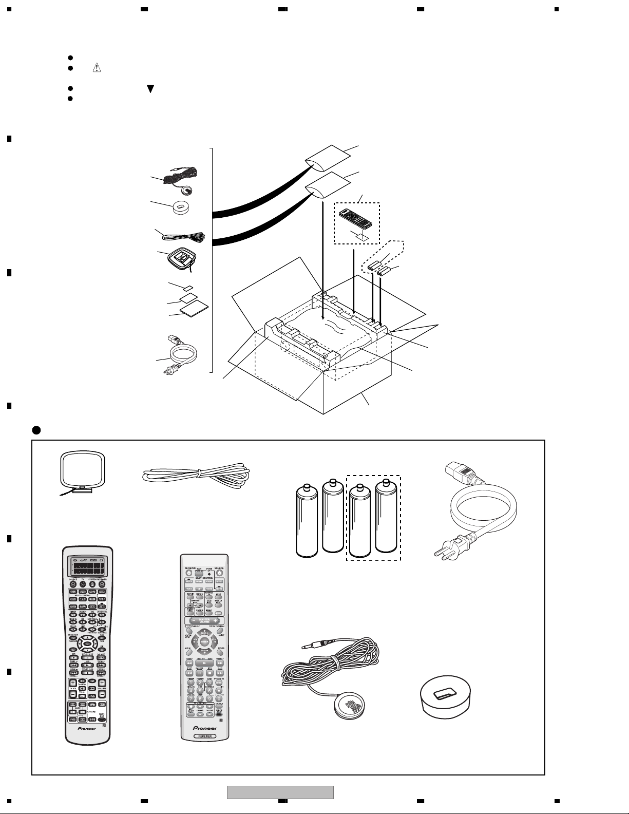
Furnished Parts
FM wire Antenna..................................................................... 1
AM loop Antenna ....................................................................1
“AA” IEC LR6 batteries ............................................................ 4
dB
3
Remote Control Unit ...............................................................1
dB
Microphone for Auto Surround Sound Setup ......................1
Microphone Stand for Auto Surround Sound Setup ........... 1
AC Power Cord........................................................................1
Operating Instructions ...........................................................1
NOTE:
Specifications and the design are subject to possible modifications without notice, due to improvements.
D
E
F
56
VSX-AX5i-S
7
8
5

1234
7 VSX-AX3-S, -K
A
B
C
Continuous Power Output (DIN)
Front...................100 W +100 W (DIN 1 kHz, THD 1%, 8 Ω)
Center ...............................100 W (DIN 1 kHz, THD 1%, 8 Ω)
Surround ...........100 W +100 W (DIN 1 kHz, THD 1%, 8 Ω)
Surround Back
......................100 W +100 W (DIN 1 kHz, THD 1%, 8 Ω)
Rated Power Output........................................ 100 W + 100 W
(20 Hz – 20 kHz, 0.09 %, 8 Ω)
Audio Section
Input (Sensitivity/Impedance)
LINE .................................................................335 mV/47 kΩ
Frequency Response
LINE .............................................. 5 Hz to 100,000 Hz
Output (Level/Impedance)
LINE ................................................................335 mV/2.2 kΩ
To ne Control
BASS ............................................................± 6 dB (100 Hz)
TREBLE.........................................................± 6 dB (10 kHz)
LOUDNESS ................................ +4/+2 dB (100Hz/10 kHz)
(at volume position –40dB)
Signal-to-Noise Ratio (IHF, short circuited, A network)
LINE .............................................................................101 dB
Signal-to-Noise Ratio
[DIN (Continuous rated power output/50 mW)]
LINE ......................................................................... 92/65 dB
+–0
3
dB
FM Tuner Section
Frequency Range....................................87.5 MHz to 108 MHz
Usable Sensitivity .............. Mono: 15.2 dBf, IHF (1.6 µV/75 Ω)
50 dB Quieting Sensitivity................................ Mono: 20.2 dBf
Stereo: 41.2 dBf
Sensitivity (DIN)............................... Mono: 1.1 µV (S/N 26 dB)
Stereo: 50 µV (S/N 46 dB)
Signal-to-Noise Ratio .........................Mono: 76 dB (at 85 dBf)
Stereo: 72 dB (at 85 dBf)
Signal-to-Noise Ratio (DIN) .................................Mono: 62 dB
Stereo: 58 dB
Distortion .................................................Stereo: 0.6 % (1 kHz)
Alternate Channel Selectivity ......................... 70 dB (400 kHz)
Stereo Separation................................................ 40 dB (1 kHz)
Frequency Response ........................ 30 Hz to 15 kHz (± 1 dB)
Antenna Input................................................75 Ω unbalanced
AM Tuner Section
Frequency Range.....................................531 kHz to 1,602 kHz
Sensitivity (IHF, Loop antenna) .................................. 350 µV/m
Selectivity .......................................................................... 30 dB
Signal-to-Noise Ratio .......................................................50 dB
Antenna................................................................Loop antenna
Miscellaneous
Video Section (S jack)
Input (Sensitivity/Impedance)................................1 Vp-p/75 Ω
Output (Level/Impedance) .....................................1 Vp-p/75 Ω
Frequency Response .............................5 Hz to 10 MHz
Signal-to-Noise Ratio........................................................65 dB
Power Requirements........................ AC 220 – 230 V, 50/60 Hz
Power Consumption........................................................ 600 W
Power Consumption in Standby mode........................... 0.8 W
+–0
AC Outlet SWITCHED ................................100 W (0.8 A) MAX
dB
3
Dimensions......................... 420 (W) × 188 (H) × 464 (D) mm
Weight (without package).............................................. 18.3 kg
Video Section (Composite)
Input (Sensitivity/Impedance)
D
LINE .....................................................................1 Vp-p/75 Ω
Output (Level/Impedance)
LINE .....................................................................1 Vp-p/75 Ω
Frequency Response
LINE ....................................................5 Hz to 10 MHz
Signal-to-Noise Ratio........................................................65 dB
Furnished Parts
FM wire Antenna ......................................................................1
AM loop Antenna .....................................................................1
“AA” IEC LR6 batteries .............................................................2
Remote Control Unit ................................................................1
+–0
Microphone for Auto Surround Sound Setup........................1
dB
3
Microphone Stand for Auto Surround Sound Setup.............1
AC Power Cord .........................................................................1
Operating Instructions............................................................. 1
NOTE:
Specifications and the design are subject to possible
modifications without notice, due to improvements.
E
• Lucasfilm and THX are trademarks or registered trademarks of Lucasfilm, Ltd. and TM. Surround EX is a jointly developed
technology of THX and Dolby Laboratories, and is a trademark of Dolby Laboratories. All rights reserved. Used under
authorization.
• Manufactured under license from Dolby Laboratories. “Dolby”, “Pro Logic”, “Surround EX” and double-D symbol
are trademarks of Dolby Laboratories.
F
6
• "DTS", "DTS-ES Extended Surround" and "Neo:6" are trademarks of Digital Theater Systems, Inc.
VSX-AX5i-S
1234

5 678
A
B
C
D
E
56
VSX-AX5i-S
F
7
8
7
1234
2. EXPLODED VIEWS AND PARTS LIST
NOTES:
A
2.1 PACKING
B
C
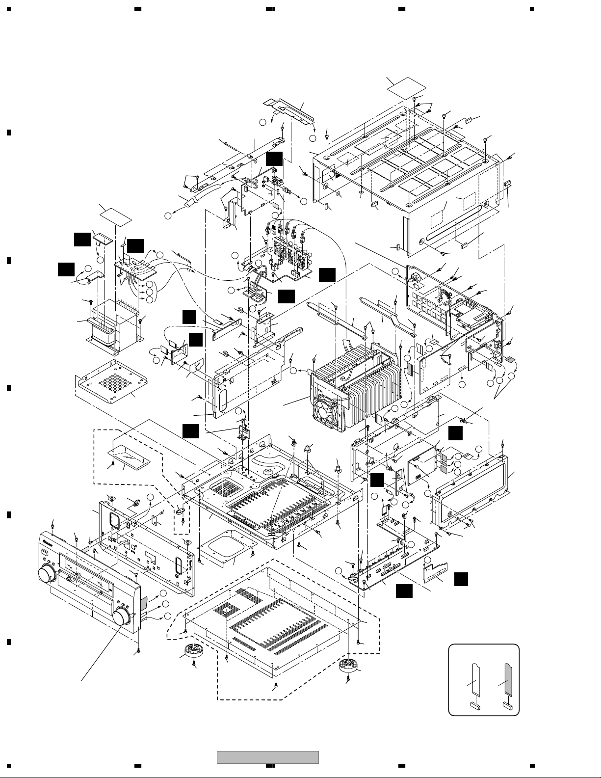
Parts marked by "NSP" are generally unavailable because they are not in our Master Spare Parts List.
The mark found on some component parts indicates the importance of the safety factor of the part.
Therefore, when replacing, be sure to use parts of identical designation.
Screws adjacent to mark on product are used for disassembly.
For the applying amount of lubricants or glue, follow the instructions in this manual.
(In the case of no amount instructions, apply as you think it appropriate.)
8
10
8
9
VSX-AX5i-S Only
11
12
14
15
1
2
3
4
5
6
7, 17-21
"Operating Instructions"
22
13
16
Accessories
D
AM Loop Antenna
(ATB7009)
E
FM Wire Antenna
(ADH7030)
Dry Cell Battery
(LR6, AA)
VSX-AX5i-S Only
AC Power Cord
(ADG7062)
F
Remote Control Unit
(VSX-AX5i-S : AXD7364)
8
1234
Remote Control Unit
(VSX-AX3-S, -K : AXD7366)
VSX-AX5i-S
Microphone for Auto
Surround Sound Setup
(APM7004)
Microphone Stand for Auto
Surround Sound Setup
(AEB7269)
5 678
PACKING parts List
Mark
No. Description Part No.
1 MIC Assy APM7004
2 MIC Stand 45 AEB7269
3 FM Wire Antenna ADH7030
4 AM Loop Antenna ATB7009
5 Caution Sheet SP,E ARM7056
Mark
No. Description Part No.
NSP 12 Alkaline Dry Cell Battery VEM1023
(LR6, AA)
13 Front Pad 45 AHA7374
14 Rear Pad 45 AHA7375
15 Packing Sheet RHC1023
A
NSP 6 Warranty Card ARY7065
7 Operating Instructions (English) See Contrast table (2)
NSP 8 Polyetylene Bag Z21-038
(0.03*230*340)
9 Remote Control Unit See Contrast table (2)
10 Battery Cover See Contrast table (2)
NSP 11 Alkaline Dry Cell Battery See Contrast table (2)
(LR6, AA)
16 Packing Case See Contrast table (2)
17 Operating Instructions (French) See Contrast table (2)
18 Operating Instructions (German)See Contrast table (2)
19 Operating Instructions (Italian) See Contrast table (2)
20 Operating Instructions (Spanish)See Contrast table (2)
21 Operating Instructions (Dutch) See Contrast table (2)
22 AC Power Cord ADG7062
>
(2) CONTRAST TABLE
VSX-AX5i-S/HYXJI, VSX-AX3-S/HYXJI and VSX-AX3-K/HYXJI are constructed the same except for the following:
Mark NO Symbol and Description
7 Operating Instructions (English) ARB7286 ARB7287 ARB7287
9 Remote Control Unit AXD7364 AXD7366 AXD7366
10 Battery Cover AZN7940 AZA7424 AZA7424
NSP 11 Alkaline Dry Cell Battery (LR6, AA) VEM1023 Not used Not used
16 Packing Case AHD8200 AHD8204 AHD8205
17 Operating Instructions (French) ARC7477 ARC7483 ARC7483
18 Operating Instructions (German) ARC7478 ARC7484 ARC7484
19 Operating Instructions (Italian) ARC7479 ARC7485 ARC7485
20 Operating Instructions (Spanish) ARC7480 ARC7486 ARC7486
21 Operating Instructions (Dutch) ARC7481 ARC7487 ARC7487
VSX-AX5i-S/
HYXJI
VSX-AX3-S/HYXJI VSX-AX3-K/HYXJI
B
C
D
E
F
56
VSX-AX5i-S
7
8
9
1234
S
2.2 EXTERIOR SECTION
A
19
61
F b
23
61
B
AI
C
8
31
AH
56
33
7
N
67
AF
6
E
32
58
N
23
L
O
P
Q
56
M
61
29
28
Q
5
R
61
61
4
24
24
26
Q
61
22
F b
61
61
20
O
52
AJ
1
66
21
D
P
52
3
AE
61
25
52
M
51
14
51
F a
65
65
R
2
52
63
(x4)
16
Refer to
"2.3 REAR PANEL
SECTION."
AD
52
35
63
(x10)
17
65
15
(VSX-AX5i-S)
16
52
36
R
52
52
52
51
52
51
(VSX-AX3-S, -K)
51
61
H
52
62
15
51
(VSX-AX3-S,
-K)
15
(VSX-AX5i-S)
61
60
52
T
J
52
15
61
52
S
65
65
52
37
I
K
52
30
VSX-AX3-S, -K
D
E
F
ONLY
29
42
43
57
61
46
52
55
55
Refer to "2.5 FRONT PANEL SECTION."
D
55
61
29
61
27
9
AG
61
68
59
61
41
68
68
44
57
A
B
C
52
48
52
61
45
L
68
Refer to
"2.4 HEAT SINK
SECTION."
26
52
34
38
38
(VSX-AX5i-S)
34
53
54
N
55
38
53
E
52
49
52
48
68
K
38
26
61
11
F a
B
54
61
13
AC
VSX-AX5i-S
ONLY
A
38
C
39
H
54
50
S
10
61
64
G
52
G
12
VSX-AX5iONLY
26
55
I
61
55
S
T
J
38
O
NON-CONTACT
SIDE
CONTACT SIDE
40
10
1234
VSX-AX5i-S
>
>
>
5 678
EXTERIOR SECTION parts List
Mark
No. Description Part No.
1 PRIMARY Assy AWX7998
2 SP/PS Assy See Contrast table (2)
3 DIODE Assy AWX8017
4FAN CONNECTION Assy AWX8005
5FAN DRIVE Assy AWX8135
6 TRANS 2-1 Assy AWX8326
7 TRANS 2-2 Assy AWX7970
8 TRANS 1 Assy AWX7969
9 VH TR Assy AWX8018
10 DSP ASSY AWX8249
11 MIC AMP Assy AWX8004
12 DSP CONNECTION Assy See Contrast table (2)
13 REGULATOR Assy See Contrast table (2)
14 Bonnet Case See Contrast table (2)
15 Spacer 45A AEB7263
16 Spacer 45B AEB7264
17 Label (DD/DTS/THX) ARW7177
18 • • • • • •
19 Barrier 45 AEC7444
20 Left Beam 45 ANG7401
21 FU1 Fuse (4A) REK-106
22 Primary Angle 35 ANG7301
NSP 23 Binder ZCA-BK1
NSP 24 Mini Clamp VEC1597
25 Fan Box 45 ANG7413
26 Locking Card Spacer PNW2917
27 Trans Shield 45 ANG7400
28 Styling Sheet B AEC7437
29 Push Rivet AEC7370
30 Trans Frame 45 ANG7399
31 T1 Power Transformer ATS7329
32 FU4,FU5 Fuse (2.5A) REK1026
NSP 33 Trans Label 45 AAX7957
34 PCB Mold AMR2534
35 Bridge Frame 45F ANG7409
No. Description Part No.
Mark
36 Bridge Frame 45R ANG7410
37 J7 21P FFC/60V ADD7355
38 Card Spacer DNK2769
39 • • • • • •
40 DSP Shield 45B ANG7403
NSP 41 Under Base See Contrast table (2)
42 Screw Cover 45A See Contrast table (2)
NSP 43 Wire Saddle DEC1450
44 Styling Sheet AEC7413
45 Stabilizer 45 ANG7408
NSP 46 Panel Stay 45 AND7047
47 • • • • • •
48 Insulator See Contrast table (2)
49 Bottom Plate 45 See Contrast table (2)
50 DSP Shield 45A See Contrast table (2)
51 Screw See Contrast table (2)
52 Screw BBZ30P080FCC
53 Screw BBZ30P100FCC
54 Screw IBZ30P150FCC
55 Screw BBT30P080FCC
56 Screw ABA7066
57 Screw ABA7009
58 UL Tube ADN7007
59 Screw Cover
See "2.5 FRONT PANEL SECTION" No. 19-3
60 Screw ABA1208
61 Screw IBZ30P080FCC
62 Screw IBZ30P100FCC
63 Spacer Circle AEC7330
64 Nylon Rivet AEC7408
65 Bonnet Sheet AEB7265
NSP 66 Fuse Card AAX7099
NSP 67 Fuse Card AAX7277
68 Screw See Contrast table (2)
A
B
C
D
(2) CONTRAST TABLE
VSX-AX5i-S/HYXJI, VSX-AX3-S/HYXJI and VSX-AX3-K/HYXJI are constructed the same except for the following:
Mark NO Symbol and Description
2 SP/PS Assy AWX8308 AWX8039 AWX8039
12 DSP CONNECTION Assy AWX8299 AWX8024 AWX8024
13 REGULATOR Assy AWX8305 AWX8020 AWX8020
14 Bonnet Case AZN7899 AZN7899 AZN7897
NSP 41 Under Base ANA7138 ANA7158 ANA7158
42 Screw Cover 45A Not used AEC7414 AEC7414
48 Insulator VXA2368 PNW2766 PNW2766
49 Bottom Plate 45 ANF7031 Not used Not used
50 DSP Shield 1394A ANG7420 Not used Not used
50 DSP Shield 45A Not used ANG7402 ANG7402
51 Screw BBZ40P080FCC BBZ40P080FCC BBZ40P080FZK
68 Screw BBZ30P080FCC IBZ30P080FCC IBZ30P080FCC
56
VSX-AX5i-S/
HYXJI
VSX-AX5i-S
VSX-AX3-S/HYXJI VSX-AX3-K/HYXJI
7
8
E
F
11

1234
2.3 REAR PANEL SECTION
24
21
29
D
15
21
(VSX-AX3-S, -K
only)
21
16
(VSX-AX5i-S only)
25
(VSX-AX5i-S only)
A
33
34
B
I
2
A
3
For Exterior
Sction
C
6
E
11
21
12
4
K
36
21
29
22
29
21
32
B
5
8
AK
14
35
21
9
(VSX-AX3-S, -K)
17
For Exterior Sction
26
(VSX-AX5i-S only)
For Heat Sink Sction
D
For Front Sction
For Exterior Sction
E
19
NON-CONTACT
SIDE
CONTACT SIDE
9
D
7
L
11
T
19
10
For Exterior Sction
H
VSX-AX5i-S only
27
20
For Exterior Sction
21
28
F
31
12
1234
VSX-AX5i-S
30
For Exterior Sction

>
>
5 678
REAR PANEL SECTION parts List
Mark
No. Description Part No.
1• • • • • •
2 COMPONENT Assy See Contrast table (2)
3 7.1CH I/O Assy See Contrast table (2)
4 VIDEO Assy See Contrast table (2)
5V-AUDIO IN Assy See Contrast table (2)
Mark
No. Description Part No.
21 Screw BBZ30P080FCC
22 Screw IBZ30P100FCC
23 • • • • • •
24 Screw VPZ30P100FZK
25 Screw See Contrast table (2)
A
6 INPUT CONNECT Assy AWX8041
7 MAIN CONTROL Assy See Contrast table (2)
8 FM/AM TUNER Module AXQ7232
9 OPTICAL IN Assy AWX7978
10 COAXIAL IN Assy See Contrast table (2)
11 Rear Panel See Contrast table (2)
12 AC Inlet Assy ADX7411
13 • • • • • •
14 Speaker Sheet AAK8016
15 Cushion Circle 16B AED7052
16 Screw with Terminal See Contrast table (2)
17 J8 13P FFC/60V ADD7356
18 • • • • • •
19 J5 9P FFC/60V See Contrast table (2)
20 J6 20P FFC/60V ADD7354
26 Tuner Spacer See Contrast table (2)
27 1394 Assy See Contrast table (2)
28 Screw See Contrast table (2)
29 Screw IBZ30P080FCC
30 J16 22P FFC/60V See Contrast table (2)
31 J17 10P FFC/60V See Contrast table (2)
32 Screw ABA1208
33 Fan Motor AXM7020
34 Fan Plate ANG7153
35 Screw BBZ30P200FZK
36 Screw CBZ30P080FZK
(2) CONTRAST TABLE
VSX-AX5i-S/HYXJI, VSX-AX3-S/HYXJI and VSX-AX3-K/HYXJI are constructed the same except for the following:
Mark NO Symbol and Description
2 COMPONENT Assy AWX8293 AWX8296 AWX8296
3 7.1CH I/O Assy AWX8306 AWX7973 AWX7973
4 VIDEO Assy AWX8312 AWX8322 AWX8322
5V-AUDIO IN Assy AWX8314 AWX7991 AWX7991
7 MAIN CONTROL Assy AWX8287 AWX8291 AWX8291
VSX-AX5i-S/
HYXJI
VSX-AX3-S/HYXJI VSX-AX3-K/HYXJI
B
C
D
10 COAXIAL IN Assy AWX8300 AWX8323 AWX8323
11 Rear Panel ANC8193 ANC8197 ANC8198
16 Screw with Terminal AKE-031 Not used Not used
19 J5 9P FFC/60V ADD7430 ADD7353 ADD7353
25 Screw PMZ30P060FCC Not used Not used
26 Tuner Spacer AEB7314 Not used Not used
27 1394 Assy AWK7768 Not used Not used
28 Screw PCZ26P060FMC Not used Not used
30 J16 22P FFC/60V ADD7431 Not used Not used
31 J17 10P FFC/60V ADD7432 Not used Not used
56
VSX-AX5i-S
7
E
F
13
8
1234
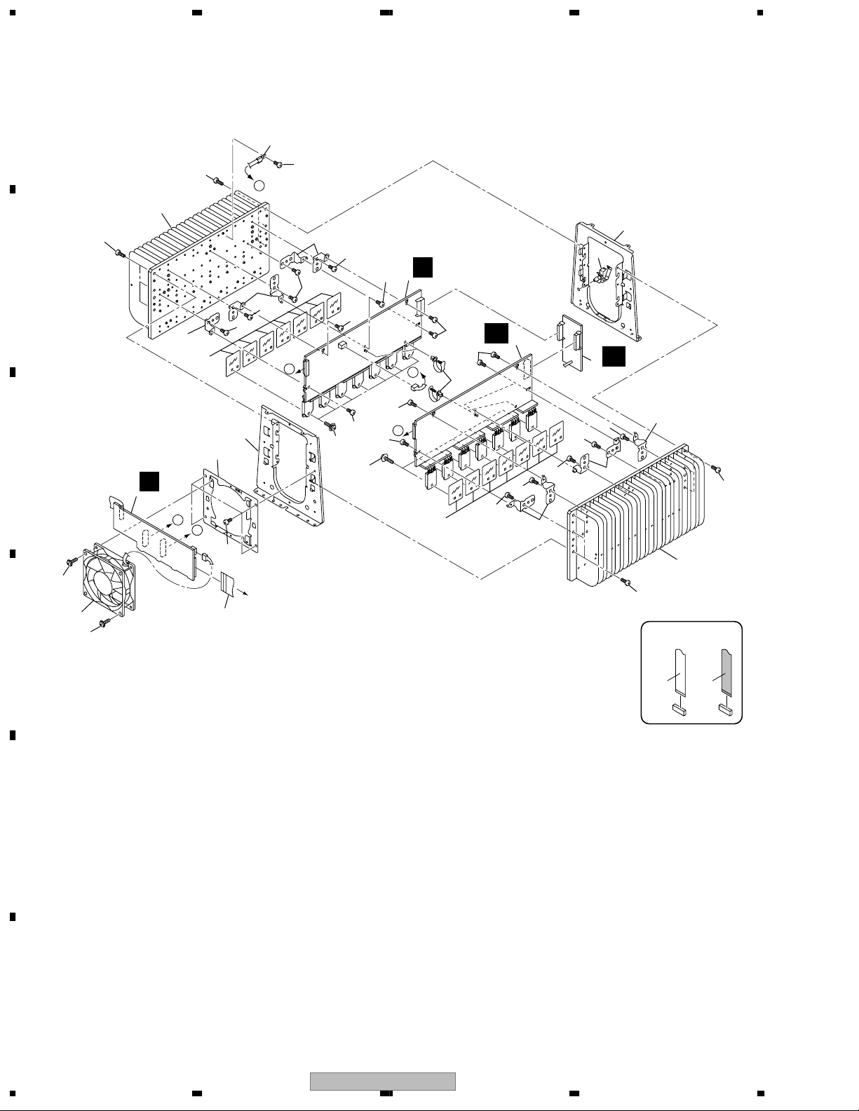
2.4 HEAT SINK SECTION
A
18
14
5
14
B
6
C
P
4
B
C
16
11
D
16
14
7
9
10
14
For Rear Panel Sction
12
14
A
6
14
Z
1
14
14
17
14
14
14
14
AA
14
A
C
8
7
3
14
14
14
14
6
6
14
14
B
17
13
2
14
9
AB
6
6
14
5
14
NON-CONTACT
E
F
14
1234
VSX-AX5i-S
SIDE
CONTACT SIDE

5 678
HEAT SINK SECTION parts List
Mark
No. Description Part No.
1POWER AMP-L Assy AWX7984
2POWER AMP-C Assy AWX7986
3POWER AMP-R Assy AWX7985
4POWER AMP IN Assy AWX7982
NSP 5 Heat Sink 45 ANH7152
6 PCB Angle 45 ANG7406
7 Mica Sheet 45 AEE7047
NSP 8 Speed Clamp AEC7445
9 H.S Angle 45 ANG7404
10 Fan Holder 80 ANG7407
11 Fan Motor AXM7023
12 J14 24P FFC/60V ADD7357
NSP 13 Wire Saddle DEC1450
14 Screw BBZ30P100FCC
15 • • • • •
16 Screw BBZ30P300FMC
17 Screw ABA7085
18 TH1 Thermistor AEX7004
>
>
A
B
C
D
E
56
VSX-AX5i-S
F
7
8
15

1234
2.5 FRONT PANEL SECTION
A
37
12
8
11
13
B
38
C
26
22
25
24
21
15
10
3
33
C
30
C
VSX-AX5i-S
ONLY
16
U
37
19-2
37
37
37
37
36
37
28
37
5
V
C
29
9
34
41
14
16
40
W
A
38
20
23
17
20
21
37
X
1
31
M
2
37
C
Y
B
4
B
32
A
35
39
6
C
37
7
39
18 (EXCEPT VSX-AX3-K)
CUT (19-2)
CUT (19-3 : VSX-AX3-S, -K ONLY)
19-1
D
37
E
F
22
NON-CONTACT
SIDE
CONTACT SIDE
16
1234
VSX-AX5i-S

5 678
FRONT PANEL SECTION parts List
Mark
No. Description Part No.
1 MULTI JOG Assy AWX8015
2 MIC & F.OPT IN Assy AWX7981
3 DISPLAY Assy See Contrast table (2)
4 HEADPHONE Assy AWX7980
5VOLUME Assy AWX7971
Mark
No. Description Part No.
21 Nut NK90FUC
22 Rotary Knob L See Contrast table (2)
23 D.Sheet See Contrast table (2)
24 Window See Contrast table (2)
25 Pioneer Badge See Contrast table (2)
A
6FRONT IN Assy AWX8186
7 STYLING Assy • • • • •
8 Door See Contrast table (2)
9 Spacer 45A AEB7263
10 Door Stay See Contrast table (2)
11 Door Shaft 35 AMR7295
12 Damper Assy (200) AXA7088
13 Door Hinge L See Contrast table (2)
14 Door Hinge R See Contrast table (2)
NSP 15 Earth Lead Wire ADH7022
16 Earth Plate B ANG7412
17 Magnet 35 AMF7007
18 FL Sheet See Contrast table (2)
19-1 Panel Base See Contrast table (2)
19-2 Magnet Holder
19-3 Screw Cover
20 Cushion Circle See Contrast table (2)
26 F.Panel See Contrast table (2)
27 • • • • •
28 J4 7P FFC/60V ADD7352
29 J1 32P FFC/60V ADD7349
30 Earth Plate A ANG7411
NSP 31 Speed Clamp AEC7445
32 J1901 Connector Assy (3P) ADE7084
33 J15 3P FFC/60V ADD7371
34 J2 11P FFC/60V ADD7350
35 J3 4P FFC/60V ADD7351
NSP 36 Wire Clip (A) VEC1335
37 Screw BPZ30P100FMC
38 Screw BBZ30P080FCC
39 Screw ABA7009
40 MECHA SW Assy AWX7995
41 Power Button See Contrast table (2)
(2) CONTRAST TABLE
VSX-AX5i-S/HYXJI, VSX-AX3-S/HYXJI and VSX-AX3-K/HYXJI are constructed the same except for the following:
Mark NO Symbol and Description
3 DISPLAY Assy AWX8316 AWX8147 AWX8147
8 Door ANB7280 ANB7280 ANB7275
10 Door Stay AAH7097 AAH7097 AAH7089
13 Door Hinge L AMR7424 AMR7424 AMR7386
14 Door Hinge R AMR7425 AMR7425 AMR7387
VSX-AX5i-S/
HYXJI
VSX-AX3-S/HYXJI VSX-AX3-K/HYXJI
B
C
D
18 FL Sheet AAK7956 AAK7956 Not used
19-1 Panel Base AMB7820 AMB7820 AMB7803
20 Cushion Circle AED7045 AED7045 AED7044
22 Rotary Knob L AAA7017 AAA7017 Not used
22 VOL Knob Not used Not used AAB7249
23 D.Sheet AAK8161 AAK8023 AAK8153
24 Window AAK8152 AAK8156 AAK8157
25 Pioneer Badge VAN1124 VAN1124 AAN7218
26 F.Panel ANB7313 ANB7317 ANB7318
41 Power Button AAD7675 AAD7675 AAD7647
56
VSX-AX5i-S
7
E
F
17
8
1234
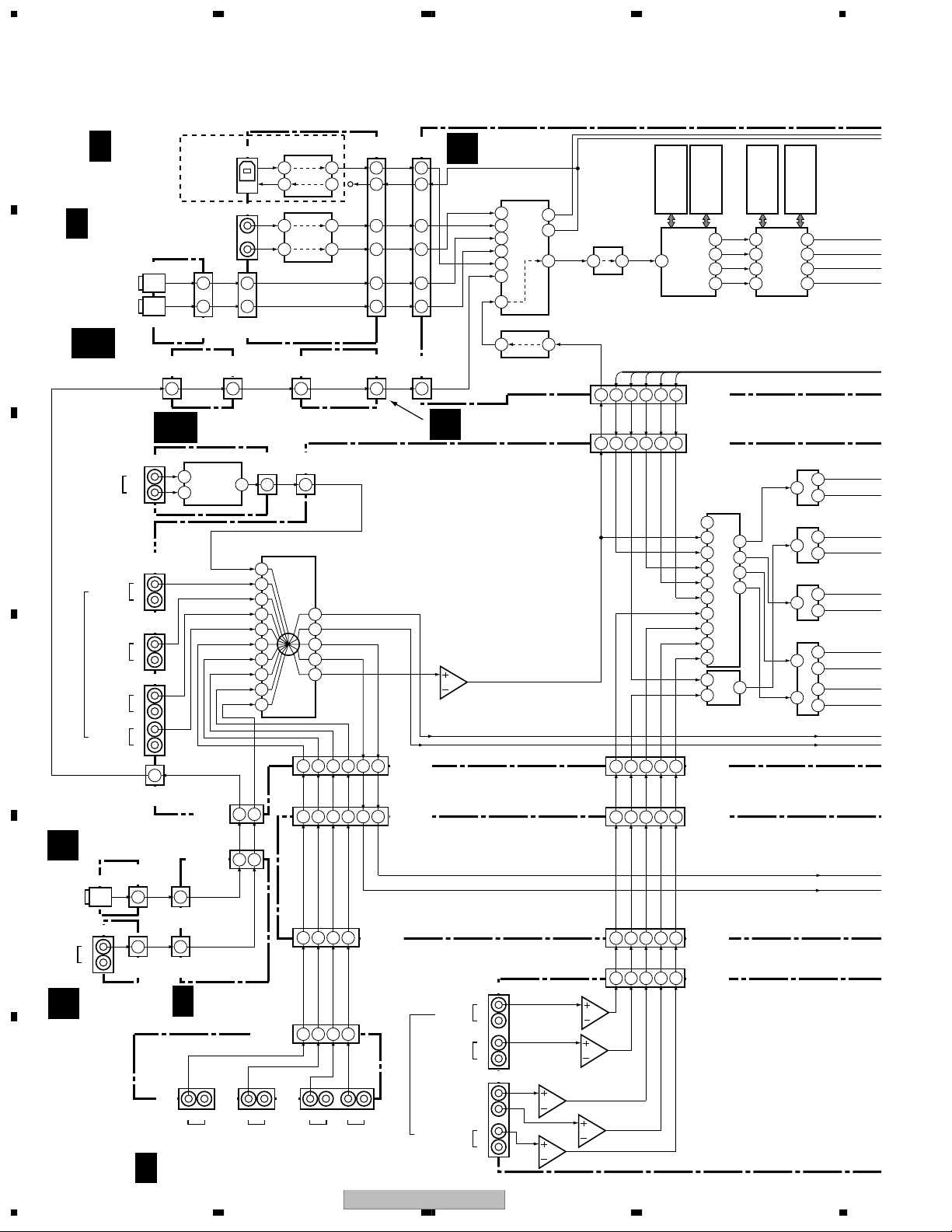
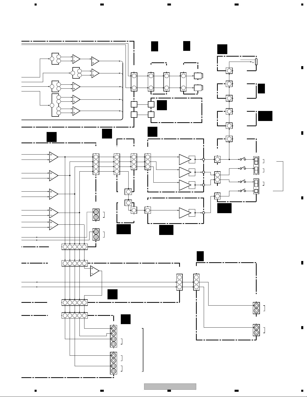
3. BLOCK DIAGRAM AND SCHEMATIC DIAGRAM
3.1 BLOCK DIAGRAM
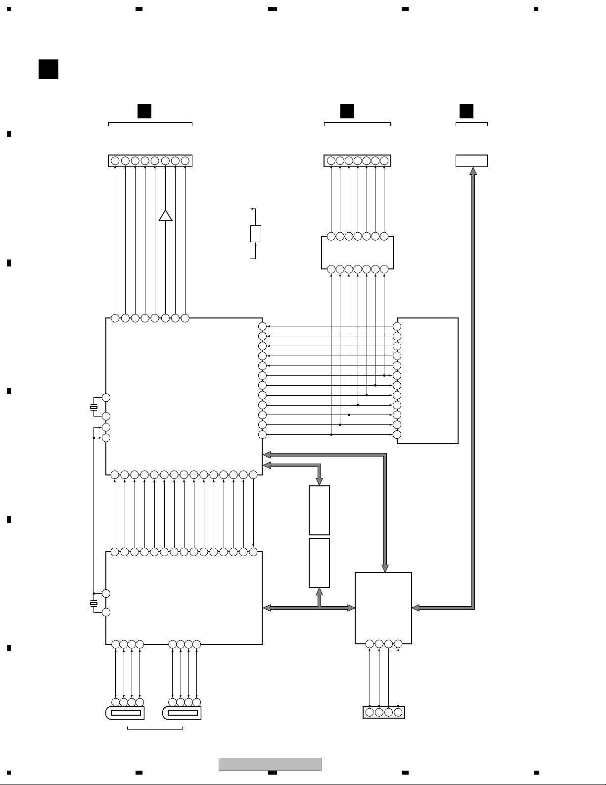
3.1.1 AUDIO BLOCK DIAGRAM
A
B
C
D
E
F
D 1/2
OPTICAL IN
ASSY
(CD-R/TAPE1)
AC
REGULATOR
ASSY
ANTENNA
IN
PHONO/
MIC & F.OPT
M
IN ASSY
JA1601
IN
DIGITAL
(FRONT)
JA1501
L
R
AUDIO
(FRONT)
VIDEO INPUT
FRONT IN
C
ASSY
18
H 1/2
COAXIAL IN
ASSY
JA1701
IN1
(TV/SAT)
IN2
JA1702
CN2412
AK
BN201
FM
AM
JA113
(1/2)
L
CD-R/
TAPE1
R
JA112
(1/2)
L
MD/
TAPE2
R
JA111
L
CD
R
L
LINE
R
OPT
8
CN3
(9P)
CN1601
(4P)
FOPT
1
CN3004
FV-L
3
CN1501
CN3005
(7P)
B 1/2
VSX-AX5i-S
ONLY
(CD-R/TAPE1)
(9P)
8
DIGITAL
USB AUDIO
IN 3
IN 4
(CD)
DIN1
2
DIN2
4
CN1701
(1/2)(9P)
CN2408
JA1681
JA1801
2
4
CN1801
(1/2)(9P)
(17P)
2
FM/AM TUNER
MODULE
TUNER
CD-R PLAY
MD PLAY
V1/IN
V2/IN
TV/SAT
DVD/LD
FVIDEO
DISPLAY
ASSY
(1/2)
CN1201
R
IN
CN201
11
CD
17
FOPT
17
CN1204
IC201
1
BA1451F
AM/FM IF
20
+ MPX IC
LINE/PHONE
CN501
(32P)
CN3006
(32P)
4
(4P)
3
(7P)
U 1/2
(1/2)
CN1202
L
VCR1
V-AUDIO IN ASSY
PCM2902EG
D+
1
Resceiver
D-
2
1
13
TC74HCU04F
DIN1
DIN2
CN1653
(17P)
CN601
(13P)
TXL TXL
7 7
1
41
42
43
44
2
3
4
5
6
6
FV-L
6
(1/2)(17P)
CN1203
L
R
IN
VCR2
IC1681
USB
IC1881
16
(13P)
10
11
14
6
V1L
10
12
V1L
12
(1/2)
8
9
11
L
CN1802
25
24
4
10
IC101
TC9274F-019
Selector
CD-R REC
MD REC
V1/OUT
V2/OUT
OUT
45
3
V2L
TVL
DVDL
12
13
15
1413
V2L
TVL
DVDL
15
1413
RLR
IN
TV/SAT
DVD/LD
(1/2)(20P)
6
2
14
16
12
10
CN1651
(28P)
18
21
V1/OUT
V2/OUT
15
14
CN1405
(1/2)(17P)
IN
CN101
(1/2)(20P)
IN6
6
OUT2
2
IN2
14
IN1
16
IN3
12
IN4
10
CN102
(28P)
OPTOPTOPT
18
CN101
(15P)
CN1401
(15P)
SURROUND
MULTI CH IN
SURROUND
S
IN1
IN2
IN3
IN4
IN6
RX0
DAUX
DSP CONNECTION
ASSY
O
IC102 (2/2)
UPC4570G2
5
7
6
FRONT
R
R
CENTER
SUB WOOFER
BACK
R
DSP ASSY
IC201
AK4114VQ
DIR & DIT
44
15
46
16
48
1
25
5
42
28
9 2
IC101
AK5380VT
AD
CN1301
IC1301 (1/2)
UPC4570G2
L
L
IC1302 (1/2)
UPC4570G2
CN1302
L
3
2
3
2
TX0
TX1
SDTO
11 9
IC701
TC74VHC157FT
Selector
ALOUT
3
2
3
2
IC1303 (1/2)
UPC4570G2
1
5
6
1
IC1304 (1/2)
UPC4570G2
SDI1
12820
16
C
FL
SL
12820
16
109
11
C
FL
SL
45
3
75
3
C
FL
SL
75
3
1
1
IC1303 (2/2)
UPC4570G2
7
IC302
IC303
SRAM
IS61LV6416-12T
IS63LV61024-12T
4
IC301
DSP1
Decoder
CN601
4
SBL
CN301
4
ALOUT
FL
C
SW
SBL
FL
C
SW
SBL
SL
SL
CN102
4
SBL
CN1403
10
CN1406
9
SBL
CN1307
9
5
7
6
(21P)
(21P)
IC103
TC9163AF
6
4
3
18
11
8
2
19
10
7
9
11
IC104
TC9215AF
(13P)
(13P)
(9P)
(9P)
10
DSPC56367PV150
10
SW
10
2
SW
12
6
SW
6
IC451
SRAM
FL
10
SL
11
SBL
48
C
138
DSPC56367PV150
5
SBL
9
C
17
SW
12
SL
10
IC471
SRAM
IC401
DSP2
PPP
TC94A07F
FL
TC94A07F
SL
TC94A07F
SBL
TC94A07F
C
SW
CD-R REC
MD REC
V1/OUT
V2/OUT
IC701
7
IC703
7
IC704
7
IC702
7
18
PPROM
IS63LV61024-12T
FL
7
SL
5
SBL
4
C
6
5
4
5
4
5
4
5
4
20
21
IS61LV6416-12T
VSX-AX5i-S
1234
5 678
A
15
16
IC541
AK4383VT
11
12
15
16
13
14
IC601 (1/2)
NJM4565MD
LPF Amp.
2
3
15
3
16
2
3
2
3
6
5
NJM4565MD
1
IC661 (1/2)
1
NJM4565MD
LPF Amp.
IC621 (1/2)
NJM4565MD
1
LPF Amp.
IC621 (2/2)
7
NJM4565MD
LPF Amp.
FL
SL
SBL
C
IC521
AK4383VT
IC501
AK4383VT
3
IC561
AK4383VT
3
3
The details please refer to next page.
MAIN CONTROL
L
ASSY
IC711 (2/2)
UPC4570G2
5
7
6
IC713 (2/2)
UPC4570G2
5
7
6
IC713 (2/2)
UPC4570G2
5
7
6
IC712
UPC4570G2
5
7
6
3
1
2
CD-R REC
MD REC
V1/OUT
V2/OUT
CN103
(9P)
CN1404
(9P)
64
8
1
2
C
FL
SL
SW
SBL
46
2
9
8
IC681 (1/2)
MIX Amp.
2
1
NJM4565MD
2
1
3
CN801
(24P)
13
7
3
9
JA113
(2/2)
JA112
(2/2)
5
7
6
IC641 (1/2)
LPF Amp.
P
CN4001
FL
SL
SBL
C
CD-R/
L
TAPE1
R
OUT
MD/
L
TAPE2
R
OUT
IC1541
UPC4570G2
SW Amp.
FL
CN101
(2/2)(20P)
SBL
SW
SL
C
CN701
CN702
(22P)
(10P)
4
2
OUT1
OUT2
CN401
(22P)
CN402
(10P)
POWER
AMP IN ASSY
CN4003
CN4401
(19P)
12
CN4002
C
8
(19P)
CN4402
CN4454
(17P)
10
(10P)
5
3
1
FL
SL
SBL
CN4453
C
(24P)
12
18
22
16
AA
POWER AMP-R
ASSY
H 2/2
COAXIAL IN
ASSY
CN1802
(2/2)(20P)
CN1801
(2/2)(9P)
4
2
T
Refer to "3.1.3 1394
BLOCK DIAGRAM".
POWER AMP-L
Z
ASSY
IC4101
(17P)
13
15
17
(10P)
10
PA9009A
Power Amp.
IC4201
PA9009A
Power Amp.
IC4301
PA9009A
Power Amp.
IC4451
PA9009A
Power Amp.
AB
D 2/2
OPTICAL IN
ASSY
CN1701
(2/2)(9P)
DOUT1
6
8
6
DOUT2
8
1394 ASSY
1
3
4
1
3
4
1
3
4
1
3
4
POWER AMP-C
ASSY
CN1405
(2/2)(17P)
3
V1OL
16
V2OL
17
JA1703
JA1704
B 2/2
CN1204
(2/2)(17P)
3
16
17
HEADPHONE
Y
ASSY
2
OUT1
OUT2
FL
Y2
SL
Y3
SBL
Y3
C
CN4601
CN4603
CN4602
HP L
2
5
HP L
7
1
HP L
1
(2P)
1
(2P)
2
1
(2P)
1
AD
Y1
V-AUDIO IN ASSY
CN1951
(3P)
CN3007
(3P)
CN3001
(11P)
CN2002
(11P)
CN2004
(5P)
CN4613
(5P)
RY4601
RY4602
RY4603
RY4604
DISPLAY
ASSY
PRIMARY
ASSY
CN4611
CN4612
SP/PS ASSY
PHONES
U 2/2
AJ
L
FRONT
R
L
SURROUND
R
L
SURROUND
R
BACK
CENTER
B
C
SPEAKERS
D
CN1408
(9P)
CN1308
(9P)
INPUT CONNECT ASSY
E
86
2
1
4
C
FL
SL
SW
SBL
2
4
8
9
6
7.1 CH I/O ASSY
A
CN1303
SUB WOOFER
CENTER
L
FRONT
R
CN1304
L
SURROUND
R
L
SURROUND
BACK
R
PRE OUT
VSX-AX5i-S
56
CN1202
(2/2)
CN1201
(2/2)
L
VCR1
OUT
R
L
VCR2
OUT
R
E
F
7
8
19
1234
3.1.2 DSP BLOCK DIAGRAM
A
L
CN301
IC101
AK5380VT
AD
DSP ASSY
S
B
H
CN1802
IC201
AK4114VQ
DIR & DIT
O
CN651
C
T
CN401
IC701
TC74VHC157FT
SELECTOR
D
IC302
IS61LV6416-12T
SRAM
IC303
IS63LV1024-12T
E
SRAM
IC705
TC7SH04FU
INVERTER
IC706
TC7SH04FU
INVERTER
IC305 TC7W125FU 3 STATE BUFFER
IC301
DSPC56367PV150
DECODER
DSP1
T
20
CN402
VSX-AX5i-S
1234
F
5 678
A
IC501
AK4383VT
B
IC503
TC7SH04FU
BUFFER
IC451
IS61LV6416-12T
IC401
DSPC56367PV150
DSP2
SRAM
PPP
IC471
PPROM
IS63LV1024-12T
IC521 AK4383VT
IC541 AK4383VT
IC561 AK4382AVT
C
CN301
L
D
56
VSX-AX5i-S
E
F
7
8
21
1234
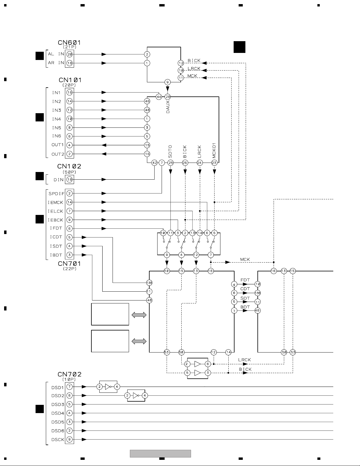
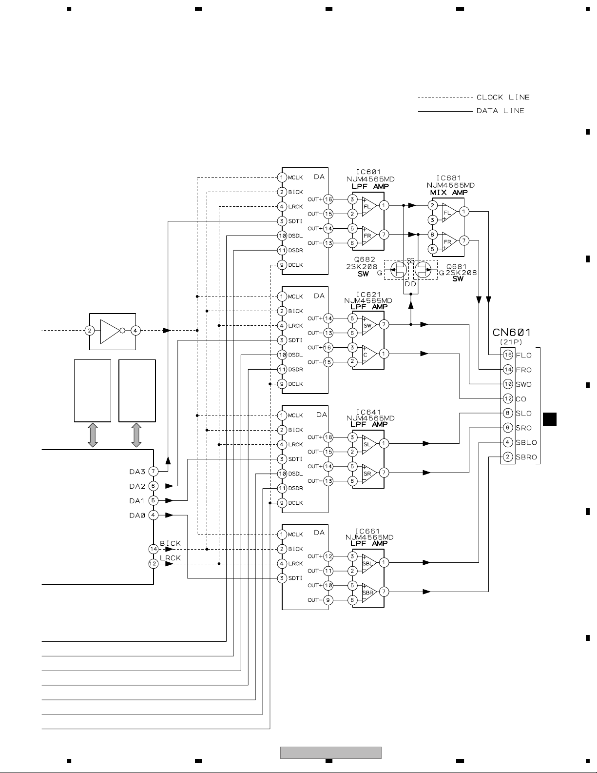
3.1.3 1394 BLOCK DIAGRAM
A
1394 ASSY
T
(1/2)
(22P)
CN401
1394_SPDIF
IE_BDT
IE_FDT
21
201718
S
IE_CDT
IE_SDT
CN701
IE_MCK
9
19
IE_BCK
IE_LRCK
14
S
CN702
DSD1
DSD2
DSD3
DSD4
DSD5
DSD6
16
4567892
(10P)
CN402
DSDCLK
(2/2)
(22P)
CN401
S
CN701
B
42
IC409
TC7SZ126FU
60958
MLPCM_DATAA
6
2
MLPCM_DATA0
MCLK
MLPCM_DATA1
MLPCM_DATA2
9
MLPCM_BCK
MLPCM_LRCK
8
7
C
BCKO
LRCKO
AMCKO
IC301
PD8112A
(Gate Array)
Flow Control IC
X302
22.5792MHz
SDATA0O5SDATA1O4SDATA2O3SDATA3O
60958OUT
CONT44
CLK44K
45 44
CLK48KI
40
CLK48K
39
V+3D
IC1
3.3V REG.
NJM2391DL1-33
V+5D
SAPCMBCKI
22
SAPCMLRCKI
16
SAPCMD3I
17
SAPCMD2I
18
SAPCMD1I
19
SACDMCKO
20
SACD5O
29
SACD4O
28
SACD3O
25
SACD2O
24
SACD1O
23
SACD0O
22
17161514131218
B2
B3B4B5B6B7
IC405
A2A3A4A5A6A7A1
3456782
TC74VHC541FT
SACD_DATA0
SACD_DATA1
SAPCM_BCK
SAPCM_LRCK
SAPCM_DATA3
SAPCM_DATA2
SAPCM_DATA1
SACD_MCLK
SACD_DATA5
SACD_DATA4
SACD_DATA3
SACD_DATA2
SACD_DATA1
SACD_DATA0
SACD_DATA2
SACD_DATA3
SACD_DATA4
B1
SACD_MCLK
SACD_DATA5
F2BCK
F2LRCK
F2SLR
F2CSWEX2
F2FLREX1
DSBCKF
DSISR
IC401
DSISL
SM5816AF
DSD Converter
DSISW
DSICT
DSIFR
64 65 66 67 68 62 47 46 45 44 43
DSIFL
63
(SACD → LPCM)
D
60958IN
SDATA0I
SDATA1I
SDATA2I
SDATA3I
LRCKI
BCKI
SACDD0I
SACDD1I
SACDD2I
SACDD3I
SACDD4I
SACDD5I
SACDDAI
82
103
100
60958OUT
MLPCM_D0
MLPCM_DA
14
174
MLPCMA
60958OUT
51 52
XI
TPB0N
TPB0P
MLPCM_D011MLPCM_D1
PLLVDD
TPA0N
E
X201
24.576MHz
252629
TPB0P
TPB0N
TPA0N
123
F
(6P)
JA201
1
999872757677787980
101
102
MLPCM_BCLK
MLPCM_LRCK
13
10
KLPCM_D2
MLPCM_LRCK
TPB1N
(6P)
JA202
SACD_D0
9
158
HSDI1_D0
MLPCM_BCLK
TPB1N
TPB1P
TPA1N
333436
TPB1P
TPA1N
123
2
MLPCM_D1
MLPCM_D2
12
TPA0P
30
TPA0P
4
SACD_D1
SACD_D2
159
163
HSDI1_D1
HSDI1_D2
TPA1P
37
TPA1P
4
SACD_D3
SACD_D4
164
165
HSDI1_D3
HSDI1_D4
IC201
TSB43CA42GGW
iLINK
SACDMKI
70
SACD_D5
SACD_DA
SACD_MCK
166
167
153
HSDI1_D5
HSDI1_D6
HSDI1_CLK
(Mercury)
iceLynx-Micro
IC302
64M SDRAM
K4S641632F-TC75
IC102
AYW7033
4M Flash ROM
TXD2
(6P)
CN101
IC101
PD5787A
TXD0
RXD0
333436
RXD2
DTR2
2
1
RS232C
(For Flash)
Host CPU
RTS0
CTS0
32
CTS2
3
4
22
1234
VSX-AX5i-S

5 678
3.1.4 POWER AMP BLOCK DIAGRAM
A
B
C
D
E
56
VSX-AX5i-S
F
7
8
23
1234
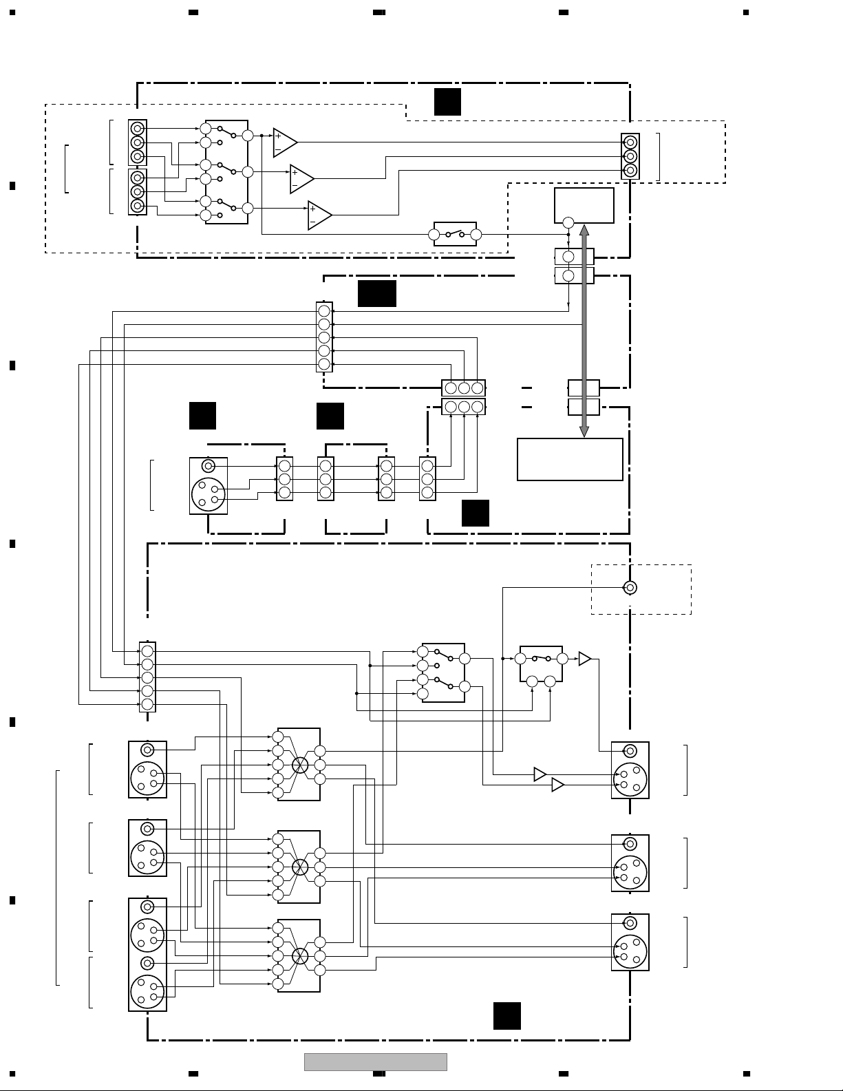
3.1.5 VIDEO BLOCK DIAGRAM
A
(DVD/LD)
VIDEO
(TV/SAT)
COMPONENT
JA1001
Y
B
P
IN
PR
Y
P
B
IN
PR
JA1002
13
14
12
1
15
2
3
5
TC74HC4053AF
4
IC101
Selector
3
2
IC1002 (1/2)
TK15450M
1
5
6
3
2
Y Amp.
IC1003 (2/2)
TK15450M
Cb Amp.
7
IC1003 (1/2)
TK15450M
Cr Amp.
1
B
CN2405
(15P)
OSD
3
OSDON
4
FV-Y
10
FV-C
9
FV
11
FRONT IN
C
ASSY
C
(FRONT)
VIDEO INPUT
VIDEO
S VIDEO
JA1501
5
6
7
CN1501
(7P)
FV
FV-C
FV-Y
U
3
2
1
CN3005
(7P)
DISPLAY
ASSY
REGULATOR ASSY
AC
FV
12
12
FV-C
14
14
FV-Y
13
13
(32P)
CN501
(32P)
CN3006
COMPONENT ASSY
I
IC1052
TC74HC4053
Selector
15 1
CN1001
(9P)
CN2404
(9P)
645
645
L
CN2412
CN2413
(9P)
CN3
CN502
(9P)
PD5948A8 [VSX-AX5i-S]
PD5899A [VSX-AX3-S, -K]
MAIN CONTROL
ASSY
(19P)
(19P)
PDC084A
13
7
3
OSD
OSDON
IC501
µ-COM
IC1051
OSD
JA1003
Y
MONITOR OUT
(COMPONENT
P
B
VIDEO)
PR
VSX-AX5i-S
ONLY
MONITOR2
OUT
JA905
BU4053BCF
OSD Selector
12
OSD
13
11
5
IC933
14
4
VIDEO
S VIDEO
VIDEO
S VIDEO
VIDEO
S VIDEO
VIDEO
S VIDEO
CN901
(15P)
JA901
(1/2)
JA902
(1/2)
JA903
(1/2)
OSD
13
OSDON
12
FV
5
FV-C
7
FV-Y
6
IN1
IN2
IN3
IN4
IN5
IN1
IN2
IN3
IN4
IN5
IN1
IN2
IN3
IN4
IN5
IC901
NJM2296M
Composite
Selector
13
9
7
5
3
IC931
NJM2296M
Y Selector
13
9
7
5
3
14
16
19
1
22
IC932
NJM2596M
C Selector
OUT1
1
OUT2
15
OUT3
11
OUT1
1
OUT2
15
OUT3
11
OUT1
10
OUT2
8
OUT3
5
OSDON
D
VCR1/
DVR
E
VCR2
IN
DVD/
LD
TV/
F
SAT
IC903
TC4W53FU
OSD Selector
7
5 6
OSD
OSDON
Q931
VIDEO ASSY
K
Q901
1
Q932
V
Y
C
V
Y
C
V
Y
C
VSX-AX5i-S
ONLY
JA904
VIDEO
S VIDEO
JA901
(2/2)
VIDEO
S VIDEO
JA902
(2/2)
VIDEO
S VIDEO
MONITOR
OUT
VCR2
OUT
VCR1/DVR
OUT
24
1234
VSX-AX5i-S

5 678
A
B
C
D
E
56
VSX-AX5i-S
F
7
8
25
1234
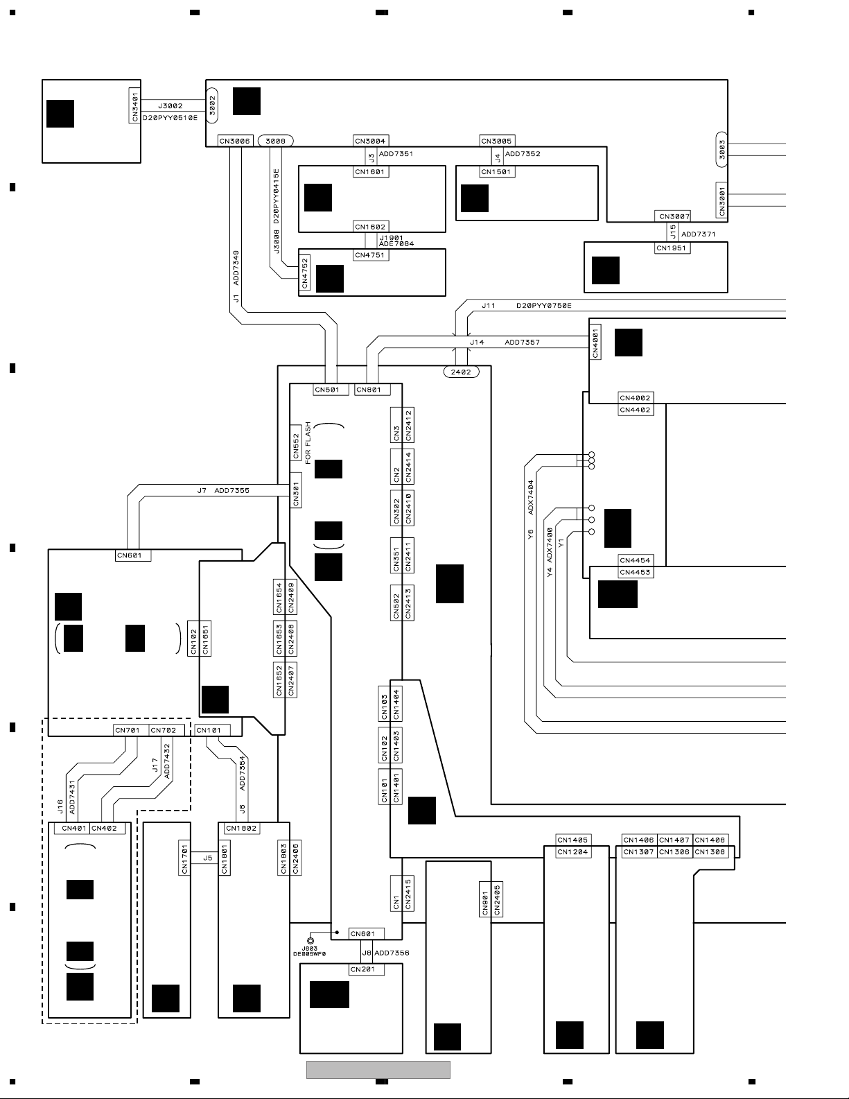
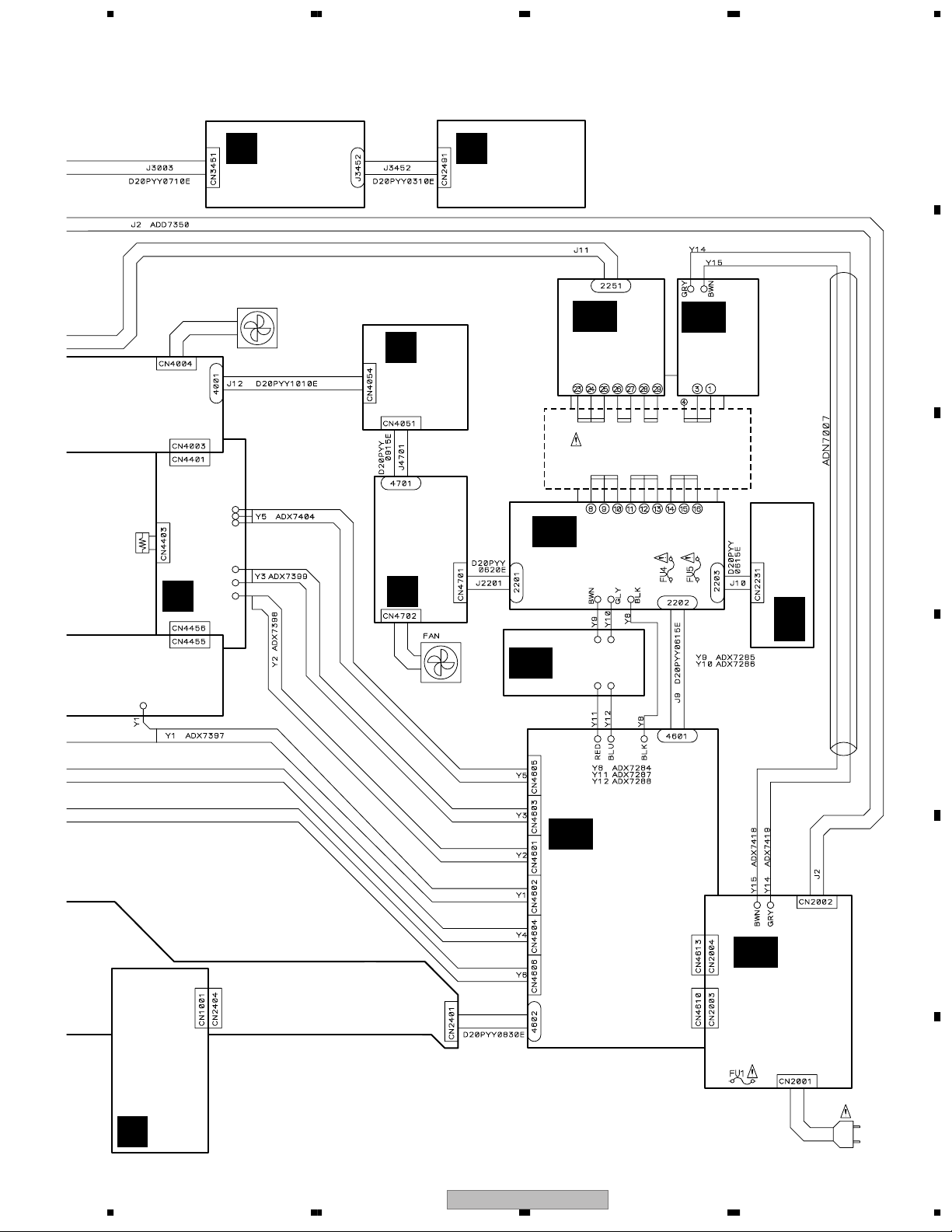
3.2 OVERALL WIRING DIAGRAM
A
VOLUME ASSY
(AWX7971)
B
C
V
DISPLAY ASSY
U
(VSX-AX5i-S : AWX8316)
(VSX-AX3-S, -K : AWX8147)
MIC & F.OPT IN
M
ASSY (AWX7981)
MIC AMP ASSY
N
(AWX8004)
FRONT IN
C
ASSY (AWX8186)
HEADPHONE
Y
ASSY (AWX7980)
P
POWER AMP IN
ASSY (AWX7982)
L 1/3- L 3/3
REGULATOR ASSY
(VSX-AX5i-S : AWX8305)
(VSX-AX3-S, -K : AWX8020)
L
MAIN CONTROL ASSY
(VSX-AX5i-S : AWX8287)
(VSX-AX3-S, -K : AWX8291)
AC
S
D
E
S 1/2, S 2/2
DSP ASSY
(AWX8249)
O
DSP CONNECTION ASSY
(VSX-AX5i-S : AWX8299)
(VSX-AX3-S, -K : AWX8024)
E
INPUT CONNECT ASSY
(AWX8041)
AA
POWER AMP-R ASSY
(AWX7985)
AB
POWER AMP-C ASSY
(AWX7986)
F
VSX-AXi5-S
ONLY
26
T 1/2, T 2/2
T
1394 ASSY (AWK7768)
1234
VSX-AX5i-S : ADD7430
VSX-AX3-S, -K : ADD7353
OPTICAL IN ASSY
(AWX7978)
D
COAXIAL IN ASSY
(VSX-AX5i-S : AWX8300)
H
(VSX-AX3-S, -K : AWX8323)
AK
FM/AM TUNER
MODULE
(AXQ7232)
VSX-AX5i-S
VIDEO ASSY
(VSX-AX5i-S : AWX8312)
(VSX-AX3-S, -K : AWX8322)
V-AUDIO IN ASSY
K
(VSX-AX5i-S : AWX8314)
(VSX-AX3-S, -K : AWX7991)
B
7.1CH I/O ASSY
(VSX-AX5i-S : AWX8306)
(VSX-AX3-S, -K : AWX7973)
A
5 678
Note : When ordering service parts, be sure to refer to "EXPLODED VIEWS and PARTS LIST" or "PCB PARTS LIST".
AEX7004
THERMISTOR
X
MULTI JOG ASSY
(AWX8015)
FAN MOTOR
(FRONT)
AXM7023
Z
POWER AMP-L ASSY
(AWX7984)
R
FAN DRIVE
ASSY
(AWX8135)
W
MECHA SW ASSY
(AWX7995)
Q
FAN CONNECTION
ASSY (AWX8005)
AH
TRANS 2-2
ASSY
(AWX7970)
POWER
TRANSFORMER
(ATS7329)
AF
TRANS 2-1
ASSY (AWX8326)
FU4, FU5 :
REK1026 (T2.5AL250V)
T1
AI
TRANS 1
ASSY
(AWX7969)
VH TR ASSY
(AWX8018)
AG
DIODE ASSY
AE
(AWX8017)
FAN MOTOR
(REAR)
AXM7020
A
B
C
D
I
COMPONENT ASSY
(VSX-AX5i-S : AWX8293)
(VSX-AX3-S, -K : AWX8296)
56
SP/PS ASSY
(VSX-AX5i-S : AWX8308)
(VSX-AX3-S, -K : AWX8039)
VSX-AX5i-S
AD
E
AJ
PRIMARY ASSY
(AWX7998)
FU1 :
REK-106 (T4AL250V)
AC IN
POWER CORD
: ADG7062
7
8
F
27
1234
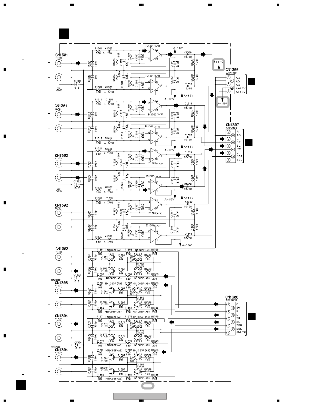
3.3 7.1 CH I/O, V-AUDIO, FRONT IN and OPTICAL IN ASSYS
7.1 CH I/O ASSY (VSX-AX5i-S : AWX8306)
A
CN1301-CN1304 ;
VSX-AX5i-S : AKB7075
VSX-AX3-S, -K : AKB7015
A
(VSX-AX3-S, -K : AWX7973)
(F)
(F) (F)
L
FRONT
R
(F)
E
(F)
B
L
SURROUND
R
MULTI CH IN
CENTER
C
SUB
WOOFER
(S)
(C)
(SB)
(S)
(C)
(SB)
(S)
(S)
(F)
(S)
(SB)
(C)
(SB)
(C)
(SB)
CN1407
E
CN1406
L
SURROUND
BACK
R
D
SUB
WOOFER
CENTER
L
FRONT
E
PRE OUT
SURROUND
SURROUND
F
R
L
R
L
BACK
R
(C)
(F)
(S)
(SB)
Preout
Mute
(C)
(F)
(SB)
(C)
(F)
(S)(S)
(SB)
E
CN1408
28
A
: The power supply is shown with the marked box.
VSX-AX5i-S
1234

5 678
VCR1
VCR2
IN
OUT
IN
OUT
TV/SAT
IN
DVD/LD
IN
B
A
V-AUDIO ASSY
(VSX-AX5i-S : AWX8314)
(VSX-AX3-S, -K : AWX7991)
L
: AUDIO SIGNAL ROUTE (Lch)
R
L
R
L
R
L
R
(DVD)
L
R
(DVD)
L
R
(DVD)
CN1201-CN1203 ;
VSX-AX5i-S : AKB7075
VSX-AX3-S : AKB7015
(DVD)
(F)
(S)
(SB)
(C)
(D)
E
CN1405
: AUDIO SIGNAL ROUTE (DVD Lch)
: AUDIO SIGNAL ROUTE (FRONT Lch)
: AUDIO SIGNAL ROUTE (SURROUND Lch)
: AUDIO SIGNAL ROUTE (SURROUND BACK Lch)
: AUDIO SIGNAL ROUTE (CENTER ch)
: AUDIO SIGNAL ROUTE (DIGITAL)
OPTICAL IN ASSY
D
(AWX7978)
B
C
D
C
L
AUDIO
R
VIDEO
VIDEO INPUT (FRONT)
S VIDEO
56
FRONT IN ASSY (AWX8186)
2DIGITAL/
DTS/MPEG
(CD-R/TAPE1)
PCM/
CN3005
U
VSX-AX5i-S
IN 1
(TV/SAT)
IN 2
OUT 1
OUT 2
(D)
(D)
(D)
(D)
(D)
(D)
CN1801
H
E
F
B C D
7
8
29
1234
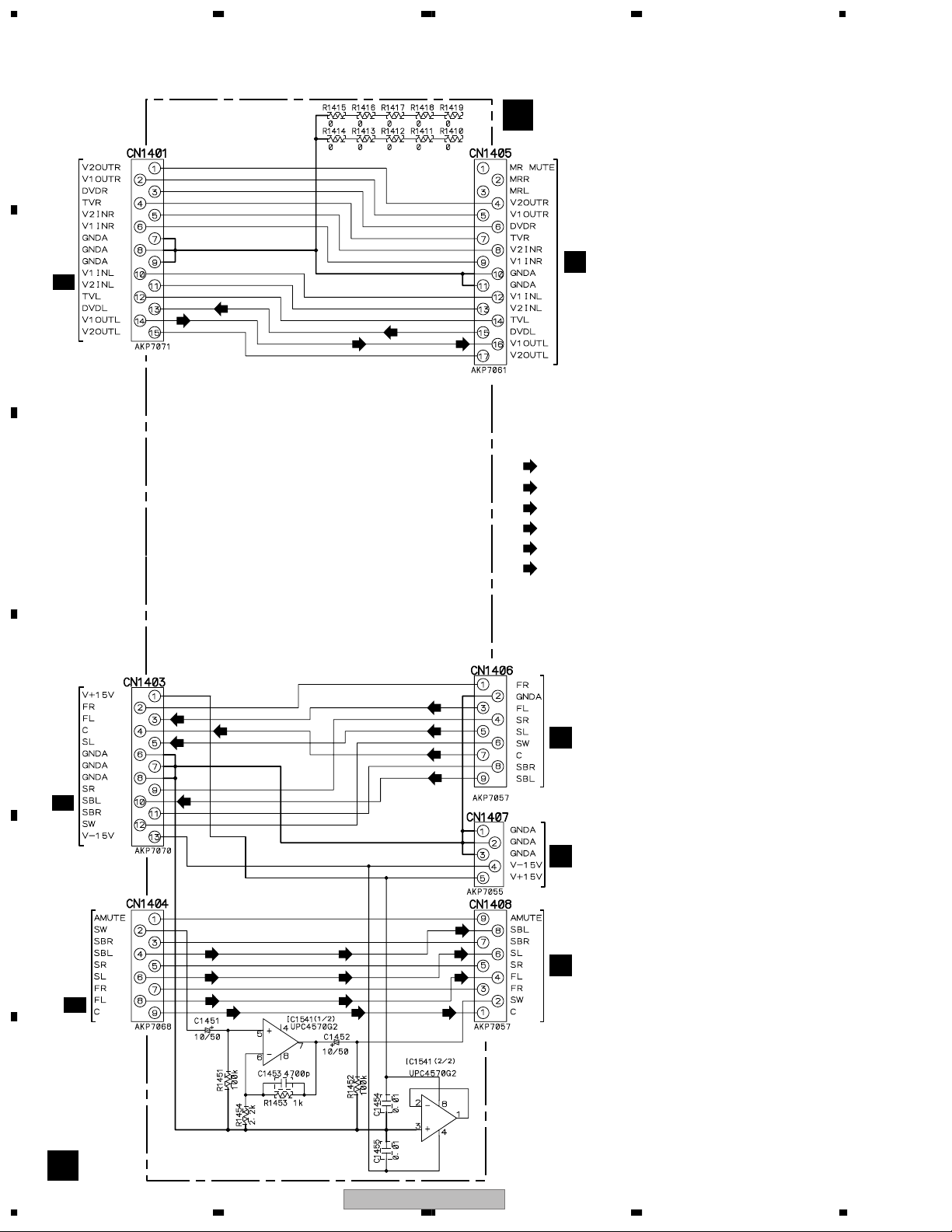
3.4 INPUT CONNECT ASSY
A
INPUT CONNECT ASSY
E
(AWX8041)
CN101
CN1204
B
L 1/3
B
C
(DVD)
(DVD)
: AUDIO SIGNAL ROUTE (Lch)
(DVD)
: AUDIO SIGNAL ROUTE (DVD Lch)
(F)
: AUDIO SIGNAL ROUTE (FRONT Lch)
(S)
: AUDIO SIGNAL ROUTE (SURROUND Lch)
(SB)
: AUDIO SIGNAL ROUTE (SURROUND BACK Lch)
(C)
: AUDIO SIGNAL ROUTE (CENTER ch)
(C)
(F)
(S)
(C)
(SB)
(SB)
(S)
(F)
CN1307
A
CN1306
A
CN1308
A
D
(F)
(C)
(S)
CN102
L 1/3
E
CN103
L 2/3
F
(SB)
(SB)
(S) (S)
(F)
(C) (C)
SW Amp.
(SB)
(F)
30
E
VSX-AX5i-S
1234
 Loading...