

Sony VSP-BZ10 Operating Instructions Manual

Digital Signage
Player
4-277-823-11 (1)
Operating Instructions
Before operating the unit, please read this manual thoroughly
and retain it for future reference.
VSP-BZ10
© 2011 Sony Corporation

WARNING
To reduce the risk of fire or electric
shock, do not expose this
apparatus to rain or moisture.
To avoid electrical shock, do not
open the cabinet. Refer servicing to
qualified personnel only.
When installing the unit, incorporate a readily
accessible disconnect device in the fixed
wiring, or connect the power plug to an easily
accessible socket-outlet near the unit. If a fault
should occur during operation of the unit,
operate the disconnect device to switch the
power supply off, or disconnect the power
plug.
WARNING: THIS WARNING IS
APPLICABLE FOR USA ONLY.
If used in USA, use the UL LISTED power
cord specified below.
DO NOT USE ANY OTHER POWER CORD.
Do not install the appliance in a confined
space, such as book case or built-in cabinet.
IMPORTANT
The nameplate is located on the bottom.
For the customers in the U.S.A.
This equipment has been tested and found to
comply with the limits for a Class B digital
device, pursuant to Part 15 of the FCC Rules.
These limits are designed to provide reasonable
protection against harmful interference in a
residential installation. This equipment
generates, uses, and can radiate radio
frequency energy and, if not installed and used
in accordance with the instructions, may cause
harmful interference to radio communications.
However, there is no guarantee that
interference will not occur in a particular
installation. If this equipment does cause
harmful interference to radio or television
reception, which can be determined by turning
the equipment off and on, the user is
encouraged to try to correct the interference by
one or more of the following measures:
Plug Cap Parallel blade
(NEMA 1-15P Configuration)
Cord Type NISPT-2 or SPT-2, two 16 or
18 AWG wires
Length Minimum 1.5m (4 ft .11in.), Less
than 2.5 m (8 ft .3 in.)
Rating Minimum 7A, 125V
Using this unit at a voltage other than 120V
may require the use of a different line cord or
attachment plug, or both. To reduce the risk of
fire or electric shock, refer servicing to
qualified service personnel.
WARNING: THIS WARNING IS
APPLICABLE FOR OTHER COUNTRIES.
1.Use the approved Power Cord (2-core mains
lead) / Appliance Connector / Plug that
conforms to the safety regulations of each
country if applicable.
2.Use the Power Cord (2-core mains lead) /
Appliance Connector / Plug conforming to
the proper ratings (Voltage, Ampere).
If you have questions on the use of the above
Power Cord / Appliance Connector / Plug,
please consult a qualified service personnel.
• Reorient or relocate the receiving antenna.
• Increase the separation between the
equipment and receiver.
• Connect the equipment into an outlet on a
circuit different from that to which the
receiver is connected.
• Consult the dealer or an experienced radio/
TV technician for help.
You are cautioned that any changes or
modifications not expressly approved in this
manual could void your authority to operate
this equipment.
All interface cables used to connect perip herals
must be shielded in order to comply with the
limits for a digital device pursuant to Subpart B
of Part 15 of FCC Rules.
This device complies with Part 15 of the FCC
Rules. Operation is subject to the following
two conditions: (1) this device may not cause
harmful interference, and (2) this device must
accept any interference received, including
interference that may cause undesired
operation.
2

For the customers in Canada
This Class B digital apparatus complies with
Canadian ICES-003.
For the customers in Europe
This product with the CE marking complies
with the EMC Directive issued by the
Commission of the European Community.
Compliance with this directive implies
conformity to the following European
standards:
• EN55103-1: Electromagnetic Interference
(Emission)
• EN55103-2: Electromagnetic Susceptibility
(Immunity)
This product is intended for use in the
following Electromagnetic Environments: E1
(residential), E2 (commercial and light
industrial), E3 (urban outdoors), E4
(controlled EMC environment, ex. TV studio).
The manufacturer of this product is Sony
Corporation, 1-7-1 Konan, Minato-ku, Tokyo,
Japan.
The Authorized Representative for EMC and
product safety is Sony Deutschland GmbH,
Hedelfinger Strasse 61, 70327 Stuttgart,
Germany. For any service or guarantee matters
please refer to the addresses given in separate
service or guarantee documents.
3
Uses for the Digital Signage Player
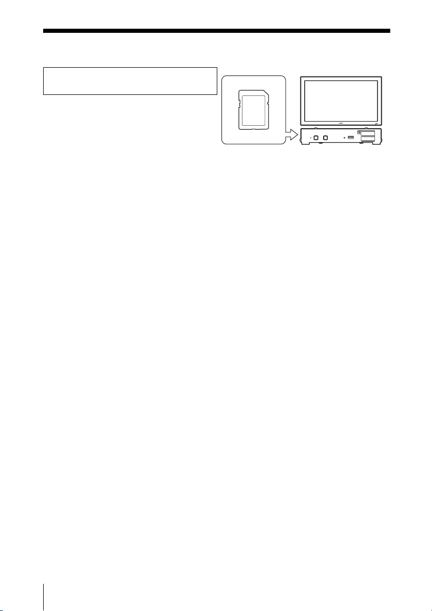
To quickly get started with digital
signage
Simply insert an SDHC Memory Card into
the player to playout the content.
, This manual “Playing Content”
“Copying Content”
• To control the playout of content on an SDHC Memory Card from a computer, see “Using
the Signage Web Manager.”
4
Uses for the Digital Signage Player

Table of Contents
Uses for the Digital Signage Player ........ 4
Precautions ............................................... 6
About This Manual ................................... 7
Names and Functions of Parts and
Playing Content ...................................... 10
Copying Content .................................... 10
Preparations for Using the Network
Using the Signage Web Manager ......... 13
Other Information ................................... 22
Troubleshooting ..................................... 28
Specifications ......................................... 38
Controls ................................................. 8
Front ............................................................. 8
Rear .............................................................. 9
Functions ............................................. 11
Assigning a Fixed IP Address to the
VSP-BZ10 ...................................... 11
Automatically Obtaining the
IP Addresses ................................... 12
Configuring Content Playout Settings ....... 13
Configuring Status Display, Control, and
Setup for the Display and Player .... 18
Returning to Default Settings .................... 21
Compatible Media and File Formats ......... 22
List of Compatible Playout Formats .......... 22
List of Media Directories ........................... 23
Configuring the Content Server ................. 24
List of Network Ports Used ....................... 25
List of Error Codes .................................... 28
Table of Contents
5

Precautions
• The specifications of this player are
subject to change for improvements
without notice.
• Screens shown by application software
may differ slightly from the illustrations
shown in this manual.
• For safety, connect the port of this player
only to a network where there is no danger
of excessive voltage or voltage surges.
• The steps described in this manual are
guaranteed only for use under the
following environment conditions.
Operating system:
– Windows XP Professional Service Pack
3 (32-bit) Japanese/English edition
– Windows Vista Business Service Pack 2
(32-bit/64-bit) Japanese/English edition
– Windows 7 Professional Service Pack 1
(32-bit/64-bit) Japanese/English edition
Browser:
Microsoft Internet Explorer 7.0, 8.0
Web server:
– Apache HTTP Server 2.2.17
– Microsoft Internet Information Services
7.5
• This player supports only SDHC Memory
Cards that are formatted with FAT32 file
systems.
• When the ACCESS indicator is lit or
flashing green, the player is reading or
writing data. Ejecting a USB flash drive
while it is being accessed may result in
damage to data or damage to the USB
flash drive.
• When you remove or insert an SDHC
Memory Card, make sure that the power
cord is disconnected.
• To ensure security on the network, setting
a user name and password is
recommended. For information on how to
make these settings, see “Setup screen” in
the “Using the Signage Web Manager”
section.
• Operations that can be performed via a
browser are functions of Signage Web
Manager.
• The current date and time must be set on
the player beforehand. You can use one of
the following two methods to perform the
configuration.
– Configure the NTP server and time
zone settings in the Signage Web
Manager.
c For details on configuration, see
the “NTP Server” and “Time
Zone” settings under the
“Settings” section of “Player
screen” in the “Using the Signage
Web Manager” section.
– Configure the date and time settings in
the Signage Web Manager.
c For details on configuration, see
the “Time” setting under the
“Setup screen” section in the
“Using the Signage Web
Manager” section.
• Microsoft, Windows, Windows Vista and Internet Explorer are registered trademarks of
Microsoft Corporation in the United States and other countries.
• The SD logo is a trademark.
• The SDHC logo is a trademark.
• All other product names, company names, etc. mentioned in this manual are trademarks or
registered trademarks of their respective owners.
6
Precautions

About This Manual
This manual describes use and operation of
the VSP-BZ10 when it is connected to a flat
panel display.
For information on connecting the player,
refer to the Installation Manual supplied
with the player.
For information on supported media (SDHC
Memory Cards and USB flash drives), refer
to the supplied Media List document or the
Media List file (Media_List.pdf) on the CDROM (Software & Manuals for Digital
Signage Player).
About This Manual
7
Names and Functions of Parts and Controls
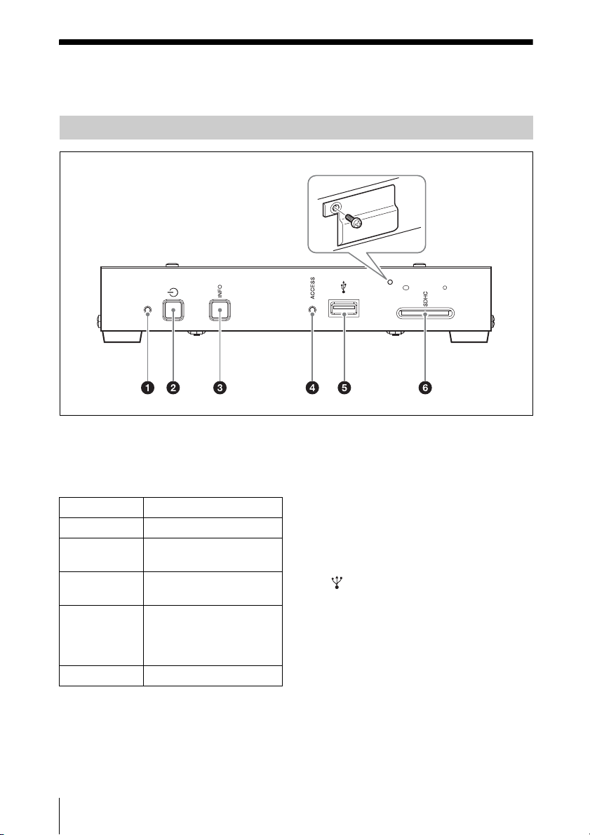
Front
a Standby indicator
This indicator lights or flashes in the
following colors in accordance with the state
of the player.
Indicator state Meaning
Lit orange Powering on
Flashing red Entering the standby state
Lit red Currently in the standby
Flashing green Readying player operation,
Lit green Player is operating
b 1 (standby) button
Hold this button for at least three seconds to
set the player to the standby state. Press the
button again to start the player.
8
Names and Functions of Parts and Controls
after powering on
state
or entering the standby
state from an operating
state
c INFO button
Displays the firmware version, IP address,
current time, and serial number on the
display.
Press the INFO button when the standby
indicator is lit green.
d ACCESS indicator
This indicator lights green when the USB
flash drive is being accessed.
e (USB) port
When sending data from a USB flash drive
using the Signage Player Management
Software, insert the USB flash drive here.
f SDHC Memory Card slot
Accepts SDHC Memory Cards.
Before inserting an SDHC Memory Card,
make sure to see “Precautions” on page 6.
This is referred to as the “memory card slot”
in this document.
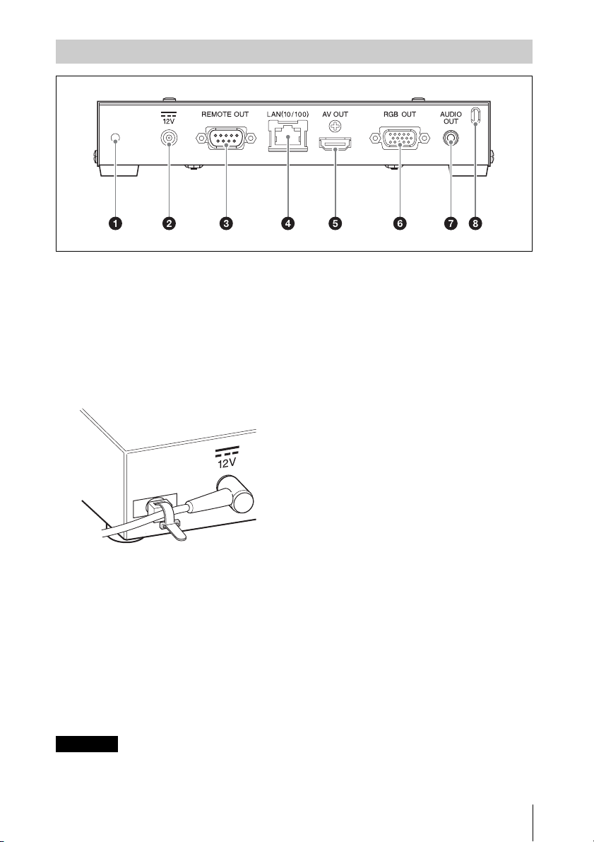
Rear
a Cable tie holder attachment hole
Attach the cable tie holder here when you
want to secure the power cord, HDMI cable,
and other cables to the player. Attach a
commercially available cable tie as
illustrated, and secure it to the cable tie
holder.
Use a cable tie that is 1.9 mm or less in
thickness, and 3.8 mm or less in width.
b 12V connector
Connects to a power cord.
c REMOTE OUT connector
Connects to a display with RS-232C
interface via an RS-232C cable.
d LAN (10/100) (network) connector
(10BASE-T/100BASE-TX)
Connects the player to a network via a
10BASE-T/100BASE-TX LAN cable.
excessive voltage to this port. Follow the
instructions for this port.
e AV OUT connector
Connects to a display via an HDMI cable.
f RGB OUT (analog) connector
Connects to a display via an RGB cable.
g AUDIO OUT connector
Connects to audio equipment via a stereo
mini plug cable.
h Security slot
Attach a commercially available security
cable here.
For details on how to use security cable,
refer to the operating instructions supplied
with the security cable.
CAUTION
For safety, do not connect the connector for
peripheral device wiring that might have
Names and Functions of Parts and Controls
9

Playing Content
Copying Content
Content such as still images, video, and
audio from an SDHC Memory Card can be
played on the display simply by inserting the
card into the memory card slot on the
VSP-BZ10.
To make advanced settings for content
playout, see “Using the Signage Web
Manager.”
Note
Content stored on a USB flash drive cannot be
played.
1 Insert an SDHC Memory Card into the
player.
2 Connect the power cord.
By default, playout of the content stored
on the SDHC Memory Card starts
automatically once the player starts up.
About playout order
The VSP-BZ10 searches the data on the
SDHC Memory Card, and plays files
compatible with the player in ASCII code
order. When content is stored in folders,
playout of folders is also according to ASCII
code order.
Notes
• We recommend using ASCII characters
when naming folders and files.
• Before inserting and removing SDHC
Memory Cards, be sure to read the
“Precautions” section.
The VSP-BZ10 uses an SDHC Memory
Card as the recording media for playout
content. Content can be copied from a
computer onto an SDHC Memory Card.
To save content stored on a computer to the
SDHC Memory Card used with the player,
we recommend creating folders and saving
content on the SDHC Memory Card. You
can use any name when creating the folders.
1 Use a new SDHC Memory Card, or
eject the SDHC Memory Card in the
player, and insert it into the memory
card slot on the computer.
2 Save the desired content to the SDHC
Memory Card.
When creating subfolders within the
SDHC Memory Card, make sure to
create no more than 32 folder sublevels.
3 Insert the SDHC Memory Card on
which the content was copied into the
unit.
Note
The SCAnnnnnnn folder (where “nnnnnnn” is
the serial number of the player) is
automatically created on any SDHC Memory
Card that has been inserted in the player. Make
sure not to delete this folder.
10
Playing Content / Copying Content

Preparations for Using the Network Functions
The VSP-BZ10 can be connected to a
network. When connected to a network, the
IP addresses of the VSP-BZ10 can be set
using one of the following two methods.
Consult your network administrator
regarding details about IP address selection.
• Assigning a fixed IP address to the
VSP-BZ10
Normally this method should be used.
• Automatically obtaining an IP
address
If the network to which the VSP-BZ10 is
connected has a DHCP server, you can
have the DHCP server automatically
assign an IP address.
You can display the IP addresses that were
assigned by pressing the INFO button.
Assigning a Fixed IP Address to the VSP-BZ10
The VSP-BZ10 requires two IP addresses:
IP Address 1 (Controller), for the Signage
Web Manager, and IP Address 2 (Player),
for the content playout function.
Under factory default settings, IP addresses
1 and 2 are set to be automatically assigned
by DHCP.
If you want to restore the default conditions
after changing the DHCP and IP address
settings, reset the player settings.
Setting IP Address 1 (Controller)
for the Signage Web Manager
First, assign IP Address 1. The IP address
assigned in this procedure is used for calling
the Signage Web Manager from a computer
on the network.
1 Connect the player and computer to a
network.
2 Connect the power cord, and wait for
about three minutes.
Depending on the network environment,
you may have to wait longer than three
minutes.
3 Start the browser of the computer.
4 Enter “ xxx.xxx.xxx.xxx (IP
Address 1 (Controller))” into the
address field, and press the Enter key
on the keyboard.
Tip
You can check the configured IP address
by pressing the INFO button on the player.
5 Click the “Setup” tab.
The “Setup” screen appears. This screen
lets you set up the Network Password.
For details, see “Setup screen” in the
“Using the Signage Web Manager”
section.
6 Click the “Network” button.
7 Under “Internet Protocol (TCP/IP),”
click “Specify IP addresses.” Then
enter the IP Address 1 in the “IP
Address 1” input fields.
8 Click the “Apply” button.
If you change IP Address 1, an error will
appear in the browser. Enter the newly
assigned IP Address 1 into the browser’s
address field.
Next, assign IP Address 2.
Setting IP Address 2 (Player) for
the content playout function
1 Start the browser of the computer.
2 Enter “ xxx.xxx.xxx.xxx (IP
Address 1 (Controller))” into the
address field, and press the Enter key
on the keyboard.
Preparations for Using the Network Functions
11

3 Click the “Setup” tab.
The “Setup” screen appears. This screen
lets you set up the Network Password.
For details, see “Setup screen” in the
“Using the Signage Web Manager”
section.
4 Click the “Network” button.
5 Under “Internet Protocol (TCP/IP),”
click “Specify IP addresses.” Then
enter the IP Address 2 in the “IP
Address 2” input fields.
6 Click the “Apply” button.
7 Under “Internet Protocol (TCP/IP),”
click “
Obtain IP addresses
automatically (DHCP).”
8 Click the “Apply” button.
Note
Depending on your router, the IP address may
not be obtained correctly. (In this case, the
Auto IP Address is set in IP Address 1. An
Auto IP Address is an IP address assigned to a
device automatically so as not to overlap with
those of other devices on networks without a
DHCP server.) Confirm the specifications and
operations of the router before use.
Automatically Obtaining the IP Addresses
If you set up the player as described below,
an IP address can be assigned automatically
by a DHCP server on the network.
1 Connect the player and computer to a
network.
2 Connect the power cord, and wait for
about three minutes.
Depending on the network environment,
you may have to wait longer than three
minutes.
3 Start the browser of the computer.
4 Enter “ xxx.xxx.xxx.xxx (IP
Address 1 (Controller))” into the
address field, and press the Enter key
on the keyboard.
Tip
You can check the configured IP address
by pressing the INFO button on the player.
5 Click the “Setup” tab.
The “Setup” screen appears. This screen
lets you set up the Network Password.
For details, see “Setup screen” in the
“Using the Signage Web Manager”
section.
Checking the automatically
assigned IP address
When an IP address has been automatically
assigned, you can call up the Signage Web
Manager as follows and check which IP
address has been assigned. The IP address
may change each time the player is turned
on. Therefore you must check the IP address
as described here every time you turn the
player off and on again.
1 Connect the player to the display.
2 Press the 1 button, and press the
INFO button after the player starts up.
3 Check the IP address that is displayed
in the dialog box on the display.
6 Click the “Network” button.
12
Preparations for Using the Network Functions
 Loading...