

Sony VPL-VW6, VPL-VW60 Operating Instructions Manual
SONY;
3-218-492-12 (1)
Video Projector
Operating
Instructions
BRAVIA
S>~O
Silicon
X-tal
Reflective
Display
HLJml™
HIGH·DEFINITION
VPL-VW60
© 2007 Sony Corporation
MULTIMEDIA
INTERFACE
WARNING
To reduce the risk of fire or electric
do
shock,
to rain or moisture.
not expose this apparatus
Declaration of Conformity
Trade Name: SONY
Model No.: VPL-VW60
Responsible Party: Sony Electronics Inc.
Address: 16530 ViaEsprillo, San Diego,CA
92127 U.S.A.
Telephone Number: 858-942-2230
To avoid electrical shock, do not
open the cabinet. Refer servicing to
qualified personnel only.
CAUTION:TOREDUCE
DO
NO
USER·SERVICEABLE
REFER
SERVICINGTOQUALIFIED
NOT
THE
REMOVE
RISKOFELECTRIC
COVER
(OR
BACK).
PARTS
INSIDE.
SERVICE
SHOCK,
PERSONNEL.
This symbol is intended to
alert the user to the presence
of
uninsulated "dangerous
voltage" within the
product'senclosurethatmay
of
sufficientmagnitude to
be
of
constitute a risk
electric
shock to persons.
This symbol is intended to
alert the user to the presence
of
important operating and
maintenance (servicing)
instructions in the literature
accompanying the
appliance.
For customers in the USA
If
you have any questionsabout this product,
you may call:
Sony Customer Information Service Center
1-800-222-7669 or http://www.sony.com!
The number below is for FCC related
matters only.
This device complies with Part
15ofthe
FCC Rules. Operation is subject to the
(I)
following two conditions:
This device
may not cause harmful interference, and (2)
this device must accept any interference
received, including interference that may
cause undesired operation.
Thisequipment has been tested and found to
comply with the limits for a Class B digital
device, pursuant to Part
15ofthe FCC
Rules. These limits are designed to provide
reasonable protection against harmful
interference ina residential installation.This
equipment generates, uses, and can radiate
if
radio frequency energy and,
not installed
and usedin accordance withthe instructions,
may cause harmful interference to radio
communications. However, there is no
guarantee that interference will not occur in
If
a particular installation.
this equipment
does cause harmful interference to radio or
television reception, which can be
determined by turningthe equipmentoffand
on, the user is encouraged to try to correct
or
the interference by one
moreofthe
following measures:
or
- Reorient
relocate the receiving antenna.
- Increase the separation between the
equipment and receiver.
- Connect the equipment into an outlet on a
circuit different from that to which the
receiver is connected.
or
- Consultthe dealer
TV
technician for help.
You are cautioned that any changes
an experienced radio/
or
modifications not expressly approved in this
manual could void your authority tooperate
this equipment.
2

Disposal of Used Lamp
This projector's lamp contains mercury and
of
shouldbe disposed
properly. Consultyour
local authorities regarding safe disposal.
The material contained in this lamp are
of
similar to those
should dispose
a fluorescent lamp, so you
of
it in the same way.
For customers in the United States
Lamp in this product contains mercury.
of
Disposal
these materials may beregulated
due to environmental considerations. For
disposal or recycling information, please
contact your local authorities or the
Electronic Industries Alliance
(www.eiae.org).
For customers in Europe
The manufacturerofthis product is Sony
Corporation, 1-7-1 Konan Minato-ku
Tokyo, 108-0075 Japan. The Authorized
Representative for EMC and product safety
is Sony Deutschland GmbH, Hedelfinger
Strasse 61, 70327 Stuttgart, Germany. For
any service orguarantee matters please refer
to the addresses given in separate service
or
guarantee documents.
Trademark Information
"BRAVIA" and
BRAVIA
are trademarks
of
Sony Corporation.
HDMI, the HDMI logo and High-Definition
Multimedia Interface are trademarks or
of
registered trademarks
HDMI Licensing
LLC.
"Blu-ray Disc" is a trademark.
3
For customers in Canada
This Class Bdigital apparatus complies with
Canadian ICES-003.
Voor de klanten in Nederland
Gooi de batterij niet weg maar
lever deze in als klein chemisch
afval (KCA).
The socket-outlet should be installed near
the equipment and be easily accessible.
CAUTION
OF
RISK
REPLACED BY AN INCORRECT
TYPE.
DISPOSED OF USED BATTERIES
ACCORDING TO THE LOCAL RULES.
EXPLOSION IF BATTERY
IS
Disposal of Old Electrical &
Electronic Equipment (Applicable
in
the European Union and other
European countries with separate
collection systems)
This symbol on the product or on its
packaging indicates that this product
shall not be treated as household waste.
Instead it shall be handed over to the
applicable collection point for the
of
recycling
equipment. By ensuring this product is
disposed
prevent potential negative consequences
for the environment and human health,
which could otherwise
inappropriate waste handling
product. The recycling
help to conserve natural resources. For
more detailed information about
recycling
your local Civic Office, your household
waste disposal service or the shop where
you purchased the product.
electrical and electronic
of
correctly, you will help
be caused by
of
of
materials will
of
this product, please contact
this
For customers in Taiwan only
JI.¥fu~~@]~)(
{i~Jt]1e-EllII
4
Table of Contents
Precautions 7
FrontJRight Side 8
RearlBottom 9
Remote Control
10
Projecting the Picture on the
Screen
Turning Offthe Power 28
Selecting the Wide Screen Mode 29
Selecting the Picture Viewing
Mode
Adjusting the Picture Quality 32
27
31
Unpacking
Step1:Installing the Projector 12
Before Setting Up the
Projector
Positioning the Projector and a
screen 14
Step2:Connecting the Projector
Connecting to a VCR
Connecting to a Computer 20
3:
Step
Position
Step4:Selecting the Menu
Language
Adjusting the Picture
11
12
17
17
21
25
Selecting to directly adjust the
desired menu item 32
Selecting desired adjust menu
items in the order
Adjusting the Picture Using Real
Color Processing 34
Using the Supplied Software to
Adjust the Picture Quality
(ImageDirector3)
Operation through the Menus 36
Picture Menu 40
Advanced Picture Menu 43
Screen Menu 44
Setup Menu 46
Function Menu 48
33
35
Installation Menu 50
Information Menu 52
About the Preset Memory No 52
5
About the HDMI Control 53
Troubleshooting 54
Warning Indicators 56
Message Lists 57
Replacing the Lamp and the Air Filter
and cleaning the Ventilation holes
(intake) 58
Cleaning the Air Filter
61
Specifications 62
Preset Signals 64
Input Signals and Adjustable!
Setting Items
67
Ceiling Installation 69
When Using the PSS-
HI
0
Projector Suspension Support .... 69
Making Fine Adjustments to the
Horizontal Picture Position 73
Index 76
6
Precautions
On
safety
• Check that the operating voltageofyour
unit is identical with the voltage
local power supply.
• Should any liquid or solid object fall into
the cabinet, unplug the unit and have it
checked by qualified personnel before
operating it further.
• Unplug the unit from the wall outlet
not to be used for several days.
• To disconnect the cord, pull it out by the
plug. Never pull the cord itself.
• The wall outlet should be near the unitand
easily accessible.
• The unit is not disconnected to the AC
power source (mains) as long as it is
connected to the wall outlet, even
unit itselfhas been turned off.
• Do not look into the lens while the lamp is
on.
• Do not place yourhand or objects near the
ventilation holes. The air coming out is
hot.
of
your
if
if
it is
the
On preventing internal heat buildup
After you turn
(ON/STANDBY) switch, do not disconnect
the unit from the wall outlet while the
cooling fan is still running.
off
the power with the 1/(9
Caution
The projector is equipped with ventilation
holes (intake) and ventilation holes
(exhaust). Do not block or place anything
or
near these holes,
may occur, causing picture degradation or
damage to the projector.
internal heat build-up
On repacking
Save the original shipping carton and
packing material; they will come in handy
you ever have to ship your unit. For
maximum protection, repack your unit as it
was originally packed at the factory.
if
7
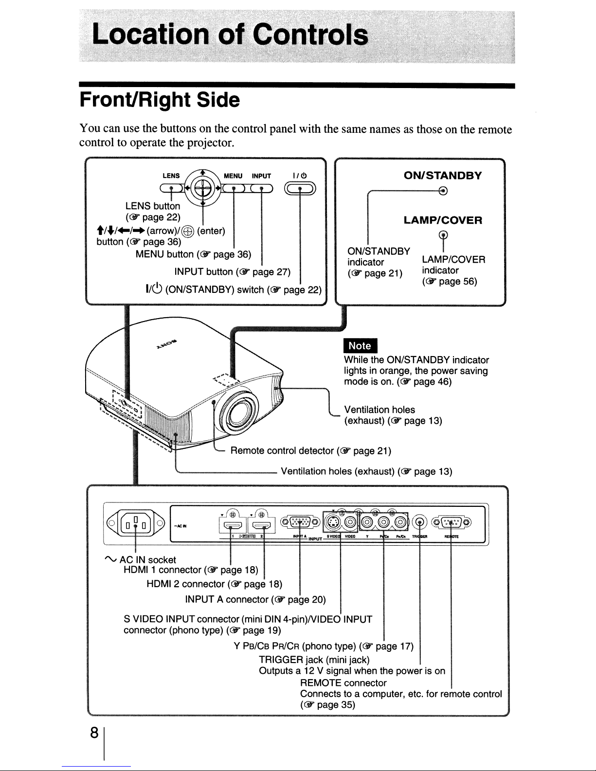
Front/Right Side
You can use the buttons on the control panel with the same namesasthose on the remote
control to operate the projector.
II
LENS button
(&
page 22)
t/./~/~(arrow)/@)
button
(cY"
page 36)
MENU button
(enter)
(&
page 36)
INPUT button
(&
1/6 (ON/STANDBY) switch
page 27)
(&
<.!>
page 22)
ON/STANDBY
indicator
(&
page 21)
ON/STANDBY
LAMP/COVER
~
LAMP/COVER
indicator
(&
page 56)
1m
While the ON/STANDBY indicator
lights in orange, the power saving
mode is on.
(&
page 46)
Remote control detector
'---------
rv
ACINsocket
HDMI1 connector(&page 18)
HDMI 2 connector(&page 18)
INPUT A connector(&page 20)
S VIDEO INPUT connector(mini DIN 4-pin)NIDEO INPUT
connector (phono type)
(&
page 19)
Y Ps/Cs
Ventilation holes (exhaust)
PRICR
TRIGGER jack (mini jack)
Outputs a 12 V signal when the power is
(phono type)
REMOTE connector
Connects to a computer, etc. for remote control
(&
page 35)
Ventilation holes
(exhaust)
(&
page 21)
(&
(&
page 17)
page 13)
(&
page 13)
on
8
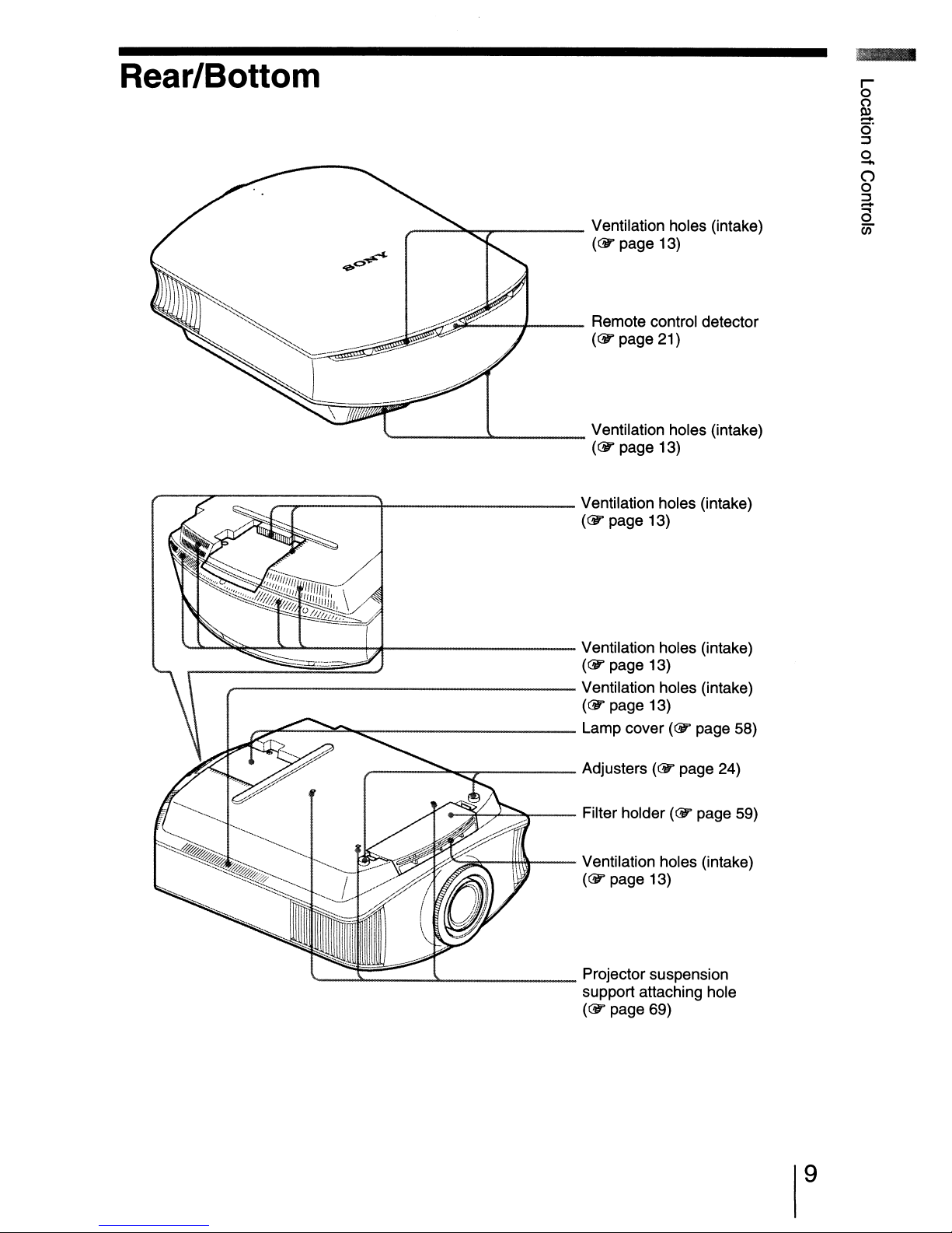
Rear/Bottom
__
~.,.-
Ventilation holes (intake)
(&
page 13)
~::...-_-+
'-
J.-
r-7....-:::::--::::;:::===+----------
~-~~:___:lo.-~---h,t----------
_-----------------
.......",,,,.e::.=--....:::::=e::::..
__
----------
,_--..::::::.""'11::"".,..._---- Adjusters
Remote control detector
(&
page 21)
Ventilation holes (intake)
(&
page 13)
Ventilation holes (intake)
(&
page 13)
Ventilation holes (intake)
(&
page 13)
Ventilation holes (intake)
(&
page 13)
Lamp cover
(&
(<!J1'
page 58)
page 24)
'--_~
-=~-+-~--
U~i:---!ff\\\---
Filter holder
Ventilation holes (intake)
(<!J1'
~
Projector suspension
support attaching hole
(&
page 13)
page 69)
(<!J1'
page 59)
9
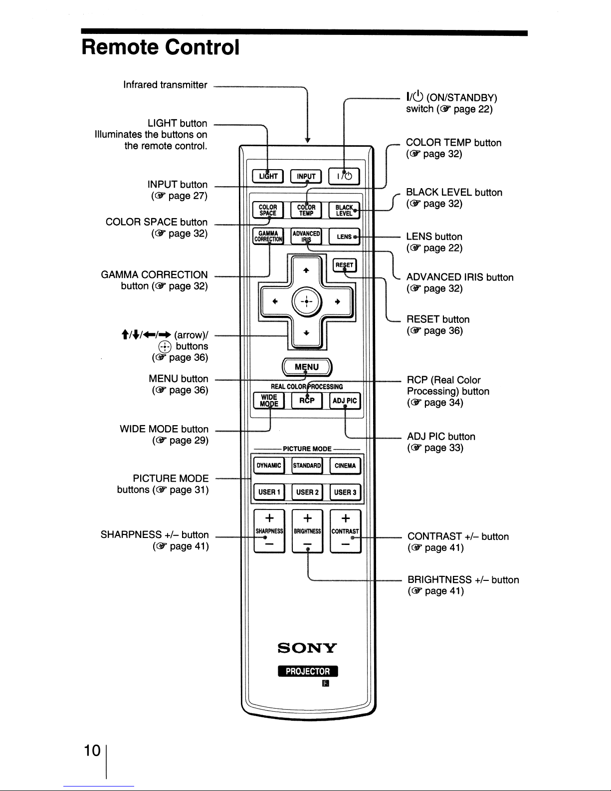
Remote Control
Infrared transmitter
LIGHT button
Illuminates the buttons on
the remote control.
I/CJ
(ON/STANDBY)
switch
COLOR TEMP button
((jJ"
--
(CY'
page 32)
page 22)
INPUT button
((jJ"
page 27)
COLOR SPACE button
(CY'
page 32)
GAMMA CORRECTION
((jJ"
button
t/
../
WIDE MODE button
page 32)
..
/~
(arrow)/
EB
buttons
(CY'
page 36)
MENU button
((jJ"
page 36)
((jJ"
page 29)
UHT
COLOR
SPACE
c&~~~~
:6~~
--PICTURE
INPUT
C_Q.rOR
1
TEMP
A~~CEDI
+
+
0)
+
MIiNU
REAL
COLORfROCESSING
R~P
I
I
I
~
)}
ADJPIC
MODE--
10
BLACIC
LEVEL
LENS
+
BLACK LEVEL button
((jJ"
I
1
'--
page 32)
LENS button
((jJ"
page 22)
ADVANCED IRIS button
((jJ"
page 32)
RESET button
((jJ"
page 36)
RCP (Real Color
Processing) button
((jJ"
page 34)
ADJ PIC button
((jJ"
page 33)
buttons
SHARPNESS
10
PICTURE MODE
(CY'
page 31)
+/-
button
((jJ"
page 41)
BEfEMAJ
~
+
SHARPNESS
-
+
BRlGHIHESS
-
SONY
t
'4i
'!J3;i']jM
..
~
+
CONTRAST
-
------:
~
CONTRAST
((jJ"
page 41)
BRIGHTNESS
((jJ"
page 41)
+/-
button
+/-
button
This section describes how to install the projector and screen, how to connect the
equipment from which you want to project the picture, etc.
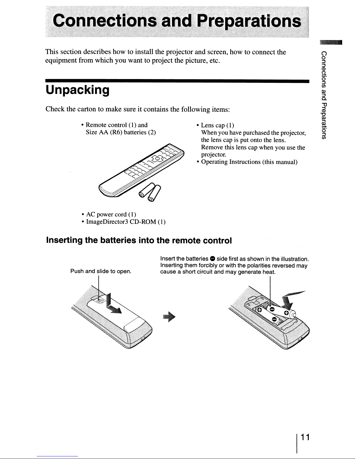
Unpacking
Check the carton to make sure it contains the following items:
• Remote control
Size AA (R6) batteries (2)
•
AC
power cord
• ImageDirector3 CD-ROM (1)
(I)
(I)
and
• Lens cap (1)
When you have purchased the projector,
the lens cap is put onto the lens.
Remove this lens cap when you use the
projector.
• Operating Instructions (this manual)
Inserting the batteries into the remote control
Push and slide to open.
Insert the
Inserting them forcibly or with the polarities reversed may
cause a short circuit and may generate heat.
batteries.
side first as showninthe illustration.
+
11
Step
1:
Installing the Projector
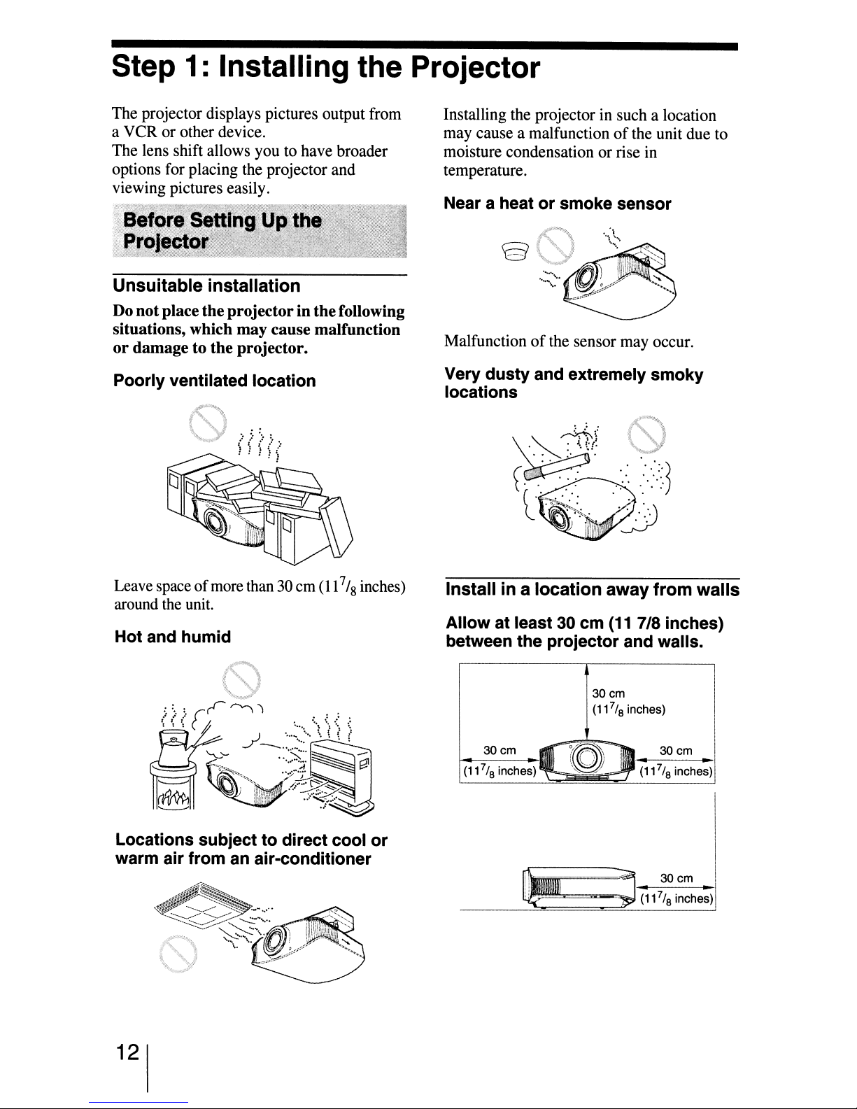
The projector displays pictures output from
a VCR or other device.
The lens shift allows you to have broader
options for placing the projector and
viewing pictures easily.
Unsuitable
installation
Do notplace theprojectorin thefollowing
situations, which may cause malfunction
or
damage to the projector.
Poorly ventilated location
i<0
"-.Y
Installing the projector in such a location
may cause a malfunction
of
the unit due to
moisture condensation or rise in
temperature.
Near a heatorsmoke sensor
Malfunctionofthe sensor may occur.
Very dusty and extremely smoky
locations
Leave spaceofmore than 30 em
(11
7
'8
around the unit.
Hot and humid
Locations subjecttodirect cool
warm air from an air-conditioner
inches)
or
Install in a
Allow at least30cm
location
away
(11
7/8 inches)
from
between the projector and walls.
30cm
7
(11
/
inches)
8
..
(11
..
(11
30cm
7
/
8
30
7
/
8
inches)
cm
inches)!
(11
30cm
7
/
8
inches)
"""""""""'".........;"J
walls
I
I
..1
I
I
"I
I
12

Improper use
Donot do anyofthe following while using
the projector.
Blocking the ventilation holes.
Ventilation holes
(intake)
'"---"""--
Ventilationholes
(exhaust)
Tip
For details on the locationofthe ventilation
holes (intake
or
exhaust), see "Location
of
Controls" on pages 8 to 9.
Tilting front/rear and left/right
""
;;J
---~
\ 15° ormore
t
Avoid using the projector tilted at an angle
of
more than15degrees.
Do not install the projector anywhere other
than on a level surface
Failing to set this mode when using the
projector
at
high altitudes may result in
uneven color uniformity and reducing the
of
reliability
the effectsofthe lamp.
When installing the unit at altitudes
When using the projector atanaltitudeof1,500
m orhigher, set "Cooling Setting"
;II
menu to "High" (@" page 46). Failing to
set this mode when using the projector at high
altitudes could have adverse effects, such
reducing the reliabilityofcertain components.
oronthe ceiling.
in
the Setup
as
15°ormore;
15° or more
!
t
--
.-<
-'--
- - -
--
- -
13
"..'.
J/'~:--T~
POs'n'9nl~a,t.h~eFOle~IQ"r)I"'cI
<";;.':'
Z;g~~~
;-
..
-~':~.
_;/,~;'·;;;t~~0':Y-"f~'
,~~-,;t~.<".h.f
N.
:-,<;:;':-~q!;r::,;;:,{:-,_~-;;("""'~.
4<c>.~c~")%;ji":.fi:4"W~~·~
'~"':"\.;
~;-+:<CT-$
a~o.k~ll:
""~wt...'%i;@;,£'ie.;';:'
,~
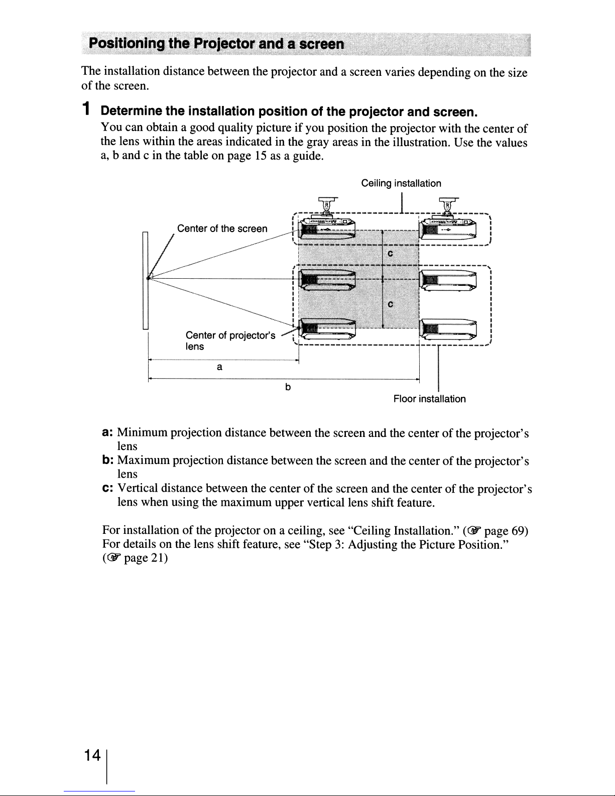
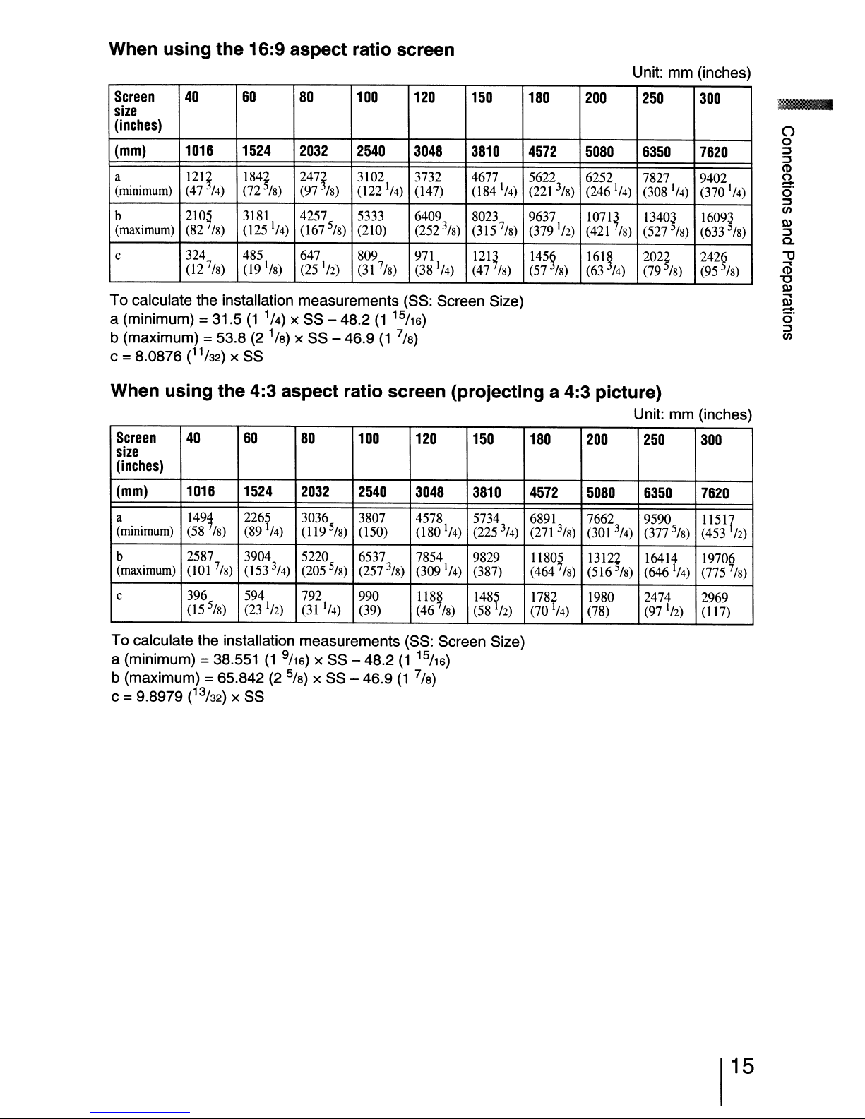
The installation distance between the projector and a screen varies depending on the size
of
the screen.
1 Determine the installation position of the projector and screen.
You can obtain a good quality pictureifyou position the projector with the center
the lens within the areas indicated in the gray areas in the illustration. Use the values
a,
band
c in the table on page15as a guide.
Ceiling installation
of
Center of projector's
lens
a
Floor installation
a:
Minimum projection distance between the screen and the centerofthe projector's
lens
b:
Maximum projection distance between the screen and the centerofthe projector's
lens
c:
Vertical distance between the centerofthe screen and the centerofthe projector's
lens when using the maximum upper vertical lens shift feature.
For installationofthe projector on a ceiling, see "Ceiling Installation."
(GY
page 69)
For details on the lens shift feature, see "Step3:Adjusting the Picture Position."
(GY
page 21)
14
When
using
the
16:9 aspect ratio screen
Unit: mm (inches)
Screen
40
60
80
100 120
150 180
size
(inches)
3
/
8
1
) (47
/
4
3810
(184'/4)
8023
) (315
1213
7
/8)
7
/8)
(mm)
a
(minimum)
b
(maximum)
c
1016
12l!
(47
/4)
210~
(82
/8)
324
7
8
02
/
1524
l84~
(72
3181
025
485 647
09'/8)
)
/8)
'/4)
2032
247!
(97
4257
067
(25
2540
3102 3732 4677 5622 6252 7827 9402
/8)
022
5333 6409
5
(210)
8
/
)
809
(31
'12)
3048
(47)
'/4)
(252
971
7/
)
(38
8
To calculate the installation measurements (SS: Screen Size)
a (minimum)
=31.5
b (maximum) =53.8
c =8.0876 (11/
When
Screen
using
40
) x SS
32
the
(1
1/
4) x SS - 48.2
)
(2
1/
x SS - 46.9
8
4:3 aspect ratio screen
60
80
15
(1
116)
)
(1
7/
8
100 120
(projecting
150
size
(inches)
(mm)
1016
1524
2032 2540
3048 3810
200
4572
(221
9637
(379
145~
(57
5080
3/
)
(246 '/4) (308 '/4) (370 '/4)
8
107Q
'12)
(421
161~
/8)
(63
a 4:3 picture)
180
4572
200 250
5080
250
6350 7620
13403
/8)
/4)
5
(527
/
202~
(79
/8)
) (633
8
Unit: mm (inches)
6350
300
1609~
/8)
242~
(95
/8)
300
7620
()
o
:::J
:::J
(1)
(')
-
c)"
:::J
en
Po>
:::J
a.
'1J
CD
'U
Po>
ii3
-
o'
:::J
en
a
(minimum)
b
(maximum)
c 396
149t 226?
(58
2587 3904 5220 6537 7854 9829 11805 13122 16414
001
(15
/8)
7
/
8)
5
)
/
8
/4)
3
4)(205
/
112)
3036
(1195/8)
(311/4)
(89
053
594 792
(23
3807
(50)
5
/
) (257
8
990
(39) (46
4578 5734
(180
3
/
) (309 '/4)
8
1188 1485
7
1
/
4
)
/
8
) (225
(387)
(58
3
112)
/
4
To calculate the installation measurements (SS: Screen Size)
(1
(1
15
7/
116)
)
8
a (minimum)
= 38.551
b (maximum) =65.842
c =9.8979 (13/
) x SS
32
(1
(2
9116)
x SS - 48.2
)
5/
x SS - 46.9
8
6891
(271
)
(464
1782 1980 2474
(70 '/4) (78) (97
7662 9590 11517
3
)
/
8
7/
)
8
(301
(516
3
/
4)
5
/
8
(377
5/
)
(453
8
'12)
19706
2969
(17)
) (646 '/4) (775
'12)
7
/
)
8
15
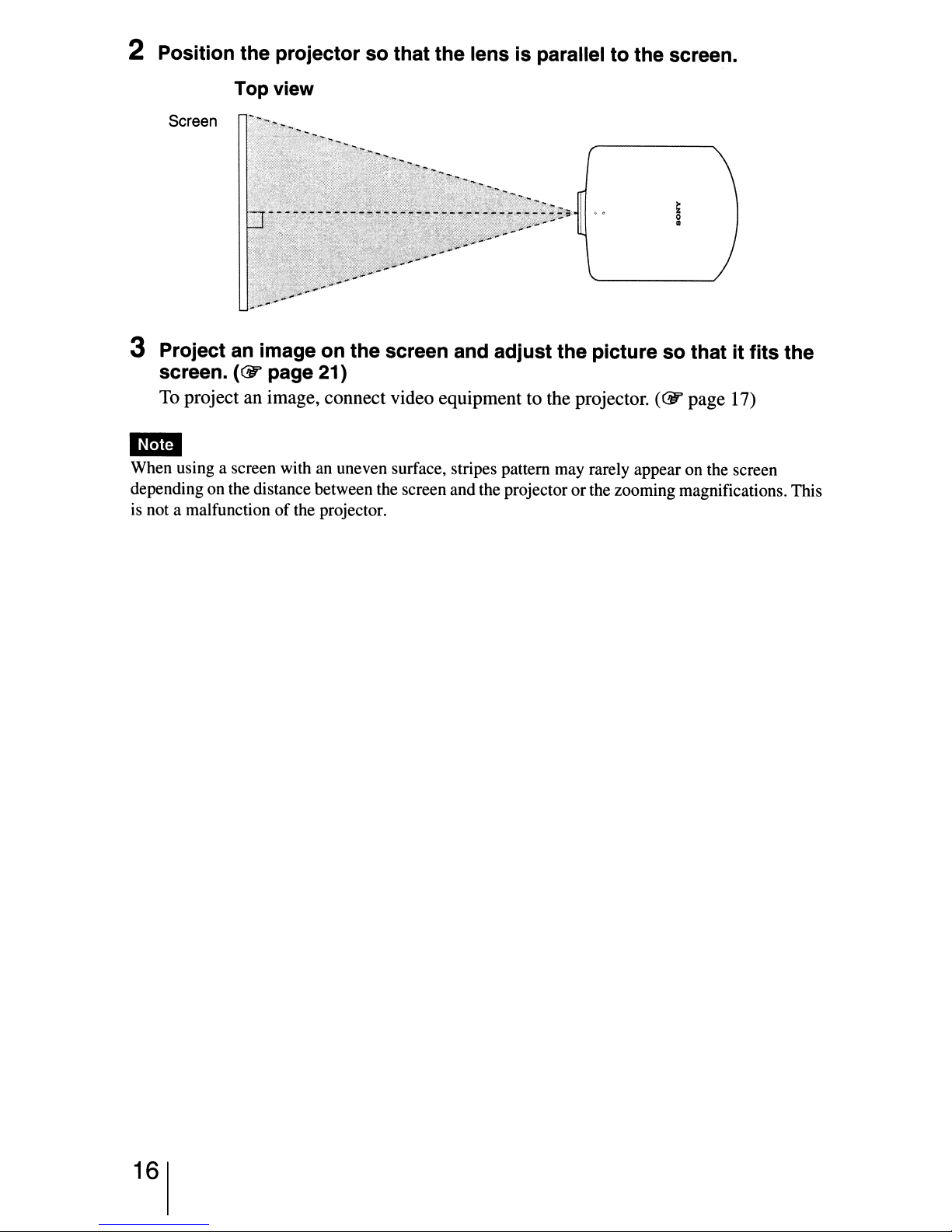
2 Position the projector so that the lens is parallel to the screen.
Top view
Screen
3 Project an image on the screen and adjust the picture so that it fits the
(@'
screen.
To project an image, connect video equipment to the projector.
page 21)
(@'
page 17)
1m
When using a screen with an uneven surface, stripes pattern may rarely appear on the screen
depending on the distance between the screen and the projector
is not a malfunction
of
the projector.
or
the zooming magnifications. This
16

Step
When making connections, be sure to do the following:
•
Tum
• Use the proper cables for each connection.
• Insert the cable plugs properly; poorconnection at the plugs may cause a malfunction or
poor picture quality. When pulling out a cable, be sure to pull it out from the plug, not
the cable itself.
• Refer to the operating instructions
To connect to a DVD player/recorder, Blu-ray Disc player or digital tuner
equipped with component video connectors
2:
Connecting the Projector
off
all equipment before making any connections.
of
the connected equipment.
Right side of the projector
IPUTSVIDEO
VIDEO
Y
Vt::r=fPR/CR
Cs.
I,
PelCa
8 0
•
PRICiI
TRIGGER
A
J
~
Component video cable (not supplied)
~
AV amplifier
..-n::::::
O.lI:··~·
DVD player/recorder, HDD
recorder, Blu-ray Disc
player, digital tuner, etc.,
with component video
connectors
Speakers
II
00
I: : : I
Cs
P-
C
h
J
~
~
: Video signal flow
17
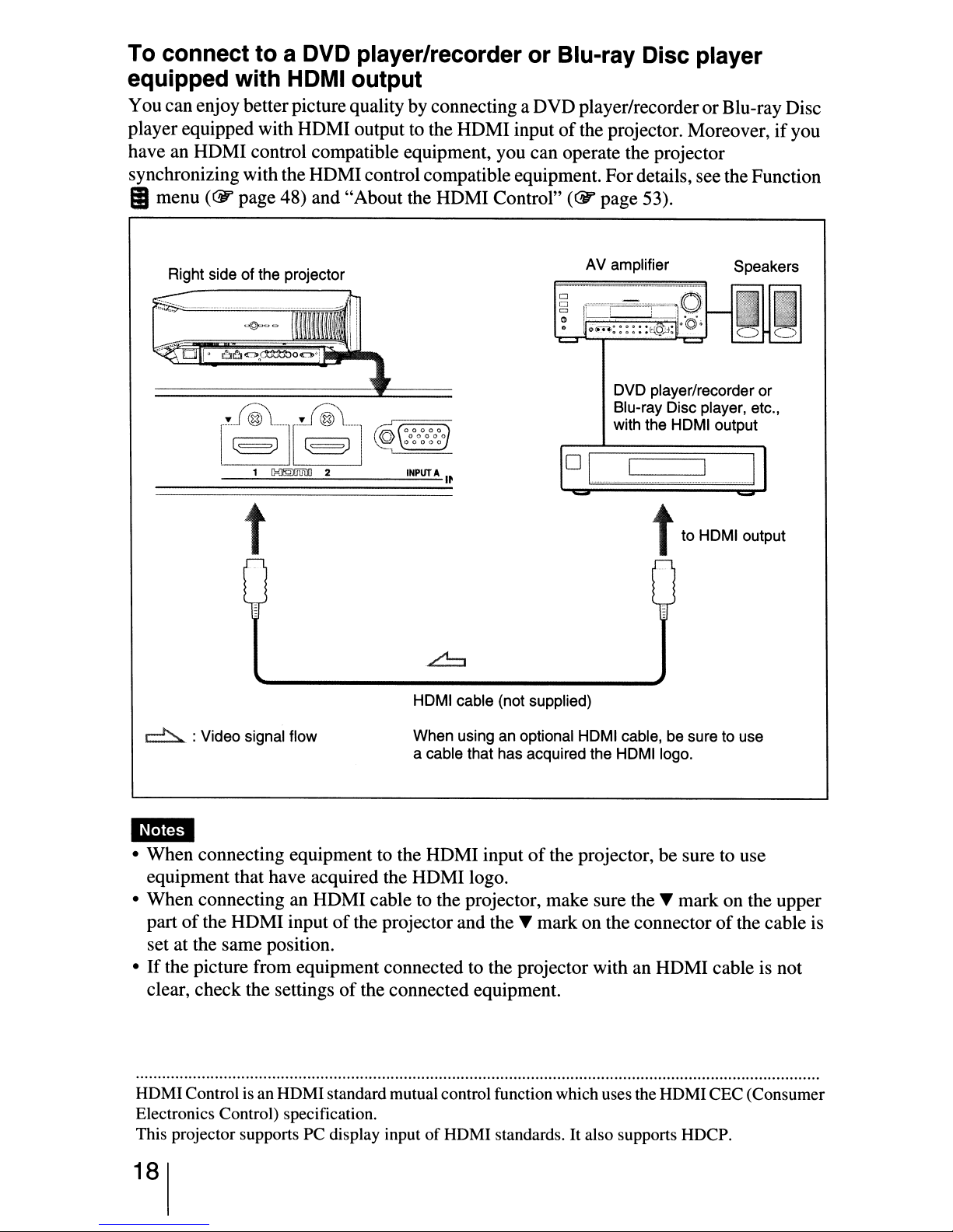
To connect to a DVD player/recorder or Blu-ray Disc player
equipped with HDMI output
You canenjoy better picturequality by connecting a DVD player/recorderorBlu-ray Disc
of
player equipped with HDMI output to the HDMI input
have an HDMI control compatible equipment, you can operate the projector
synchronizing withtheHDMIcontrol compatibleequipment. Fordetails, see the Function
II
menu
(@'
page 48) and "About the HDMI Control"
Right side of the projector
the projector. Moreover,ifyou
(@'
page 53).
INPUT
DVD player/recorder
Blu-ray Disc player, etc.,
with the HDMI output
A
I~
o I
mmmm'--
t
----'.m
to
HOMI output
..
or
.1
t
HDMI cable (not supplied)
to
~
: Video signal flow
When using an optional HDMI cable, be sure
a cable that has acquired the
HDMllogo.
1m
• When connecting equipment to the HDMI inputofthe projector, be sure to use
equipment that have acquired the HDMI logo.
• When connecting an HDMI cable to the projector, make sure the~mark on the upper
part
of
the HDMI inputofthe projector and the~mark on the connectorofthe cable is
set at the same position.
•
If
the picture from equipment connected to the projector with an HDMI cable is not
of
clear, check the settings
the connected equipment.
use
HOM!Control is an HOM!standard mutualcontrol function which uses the HOMI CEC (Consumer
Electronics Control) specification.
This projector supports PC display input
18
of
HOM! standards.Italso supports HOCP.
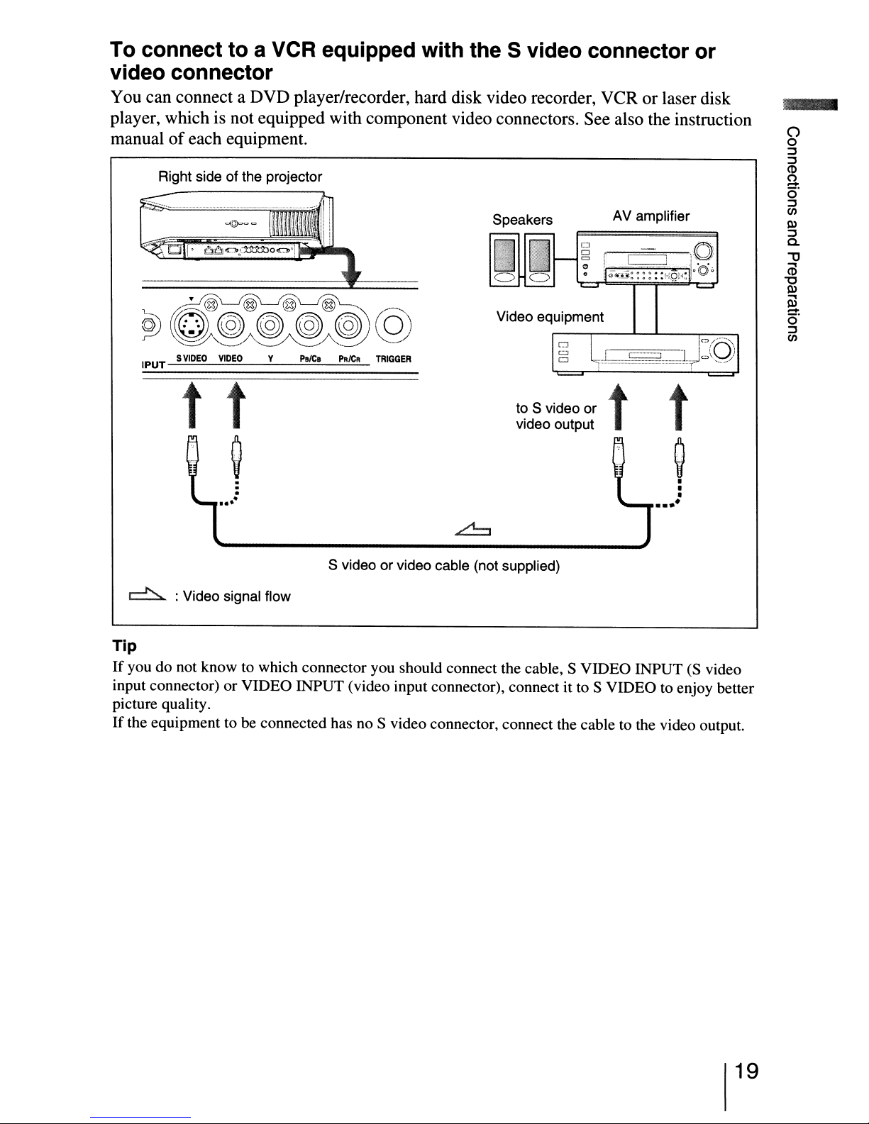
To connect to a VCR equipped with the S video connector or
video connector
You can connect a DVD player/recorder, hard disk video recorder, VCR or laser disk
player, which is not equipped with component video connectors. See also the instruction
of
manual
IPUT
each equipment.
Right side of the projector
t
y
Palea
SVIDEO
t
VIDEO
P1lICR
TRIGGER
Speakers
Video equipment
to S video or t t
video output
AV amplifier
..
f
':1
-r"
()
o
::J
::J
<D
U
o·
::J
en
Q)
::J
a.
"'0
...,
<D
"0
Q)
@
o·
-
::J
en
•
•••
~
•
•
•
~
·
·
....
·
S video or video cable (not supplied)
~
Tip
If
you do not know to which connector you should connect the cable, S VIDEO INPUT(Svideo
input connector) or VIDEO INPUT (video input connector), connect it to S VIDEO to enjoy better
picture quality.
If
the equipment to be connected has no S video connector, connect the cable to the video output.
: Video signal flow
19
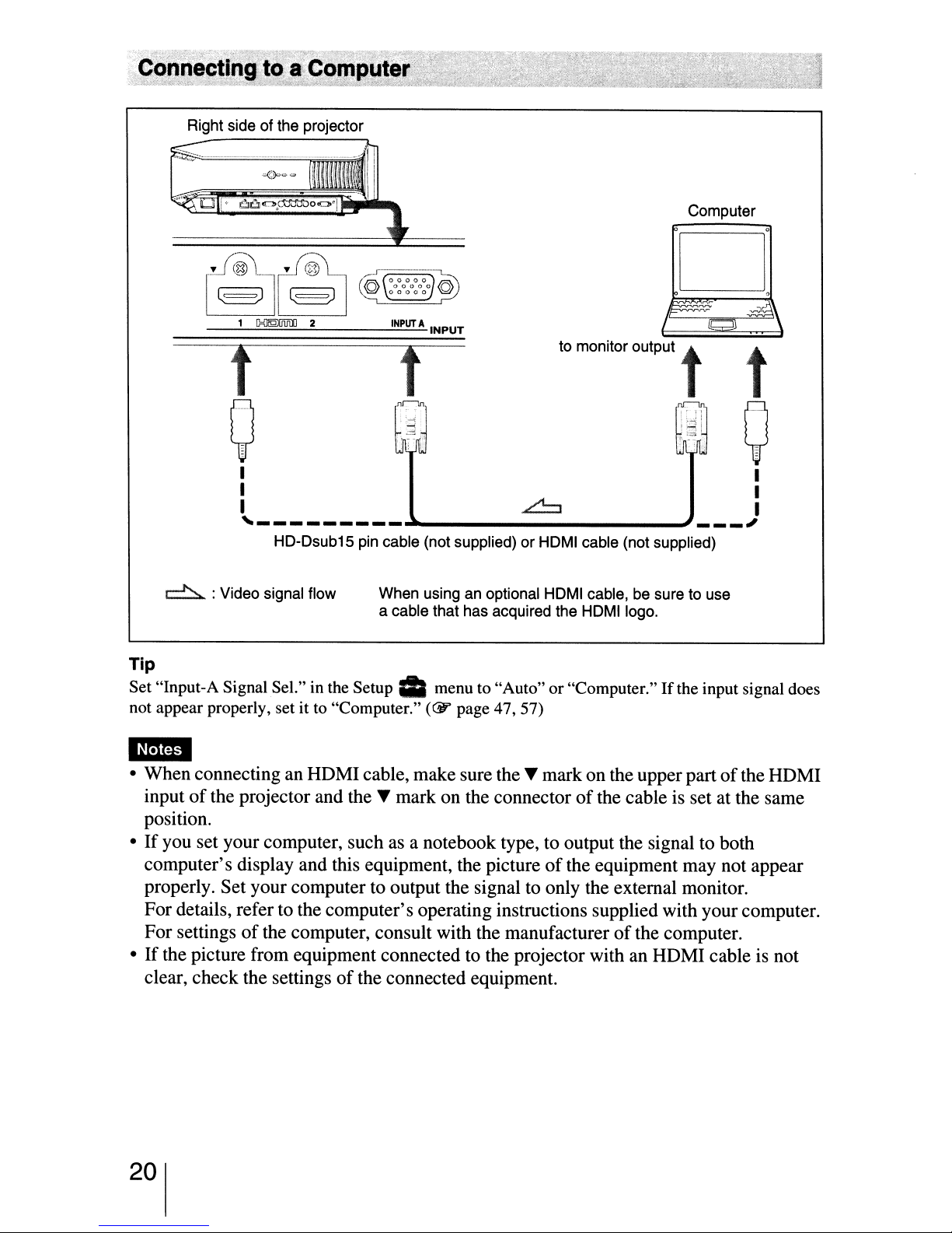
Right side of the projector
INPUT
A
Computer
INPUT
t t to monitor
....
_·····
nr-ln
.;
.~
~:I
I
ompm
r;r::~
.,igi
t t
0
..
_
__
..
··
0
I I
I I
I
,_
- - -
HO-Osub15 pin cable (not supplied)orHOMI cable (not supplied)
~
: Video signal flow
Tip
Set "Input-A Signal Sel." in the
not appear properly, set it to "Computer."
Setup'"
....
When using an optional HOMI cable, be sure to use
a cable that has acquired the HOMI logo.
menu to "Auto" or "Computer."Ifthe input signal does
(CY'
page 47, 57)
mmDI
• When connecting an HDMIcable, make sure
input
of
the projector and the ... mark on the connectorofthe cable is set at the same
position.
•
If
you set your computer, such as a notebook type, to output the signal to both
computer's display and this equipment, the picture
properly. Set your computer to output the signal to only the external monitor.
For details, refer to the computer's operating instructions supplied with your computer.
For settings
•
If
the picture from equipment connected to the projector with an HDMI cable is not
clear, check the settings
of
the computer, consult with the manufacturerofthe computer.
of
the connected equipment.
~
the'"
J
mark on the upper partofthe HDMI
of
the equipment may not appear
I
'"
20
Step
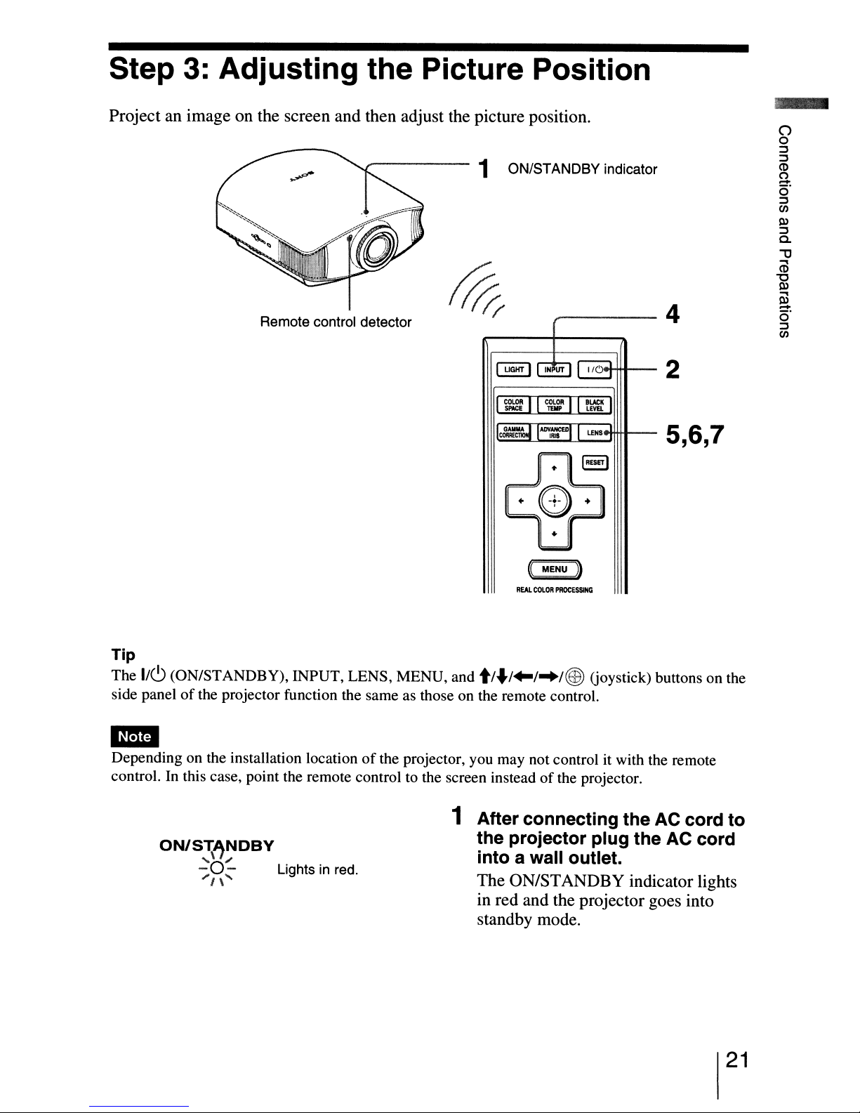
Project an image on the screen and then adjust the picture position.
3:
Adjusting the Picture Position
,....-----
Remote control detector
1 ON/STANDBY indicator
-----4
c;.H+t1--2
«MENU )
REAL
COlOR
PROCESSING
5,6,7
Tip
The
1/(9
side panel
(ON/STANDBY), INPUT, LENS, MENU, and
of
the projector function the same as those on the remote control.
t/
...
/+-/
..
/@)
(joystick) buttons on the
1m
Depending on the installation locationofthe projector, you may not control it with the remote
control. In this case, point the remote control to the screen instead
1 After connecting the AC cord to
ON/S\~NDBY
,
-0-
"'/\'
~
Lightsinred.
the projector plug the AC cord
into a wall outlet.
The ON/STANDBY indicator lights
in red and the projector goes into
standby mode.
of
the projector.
21
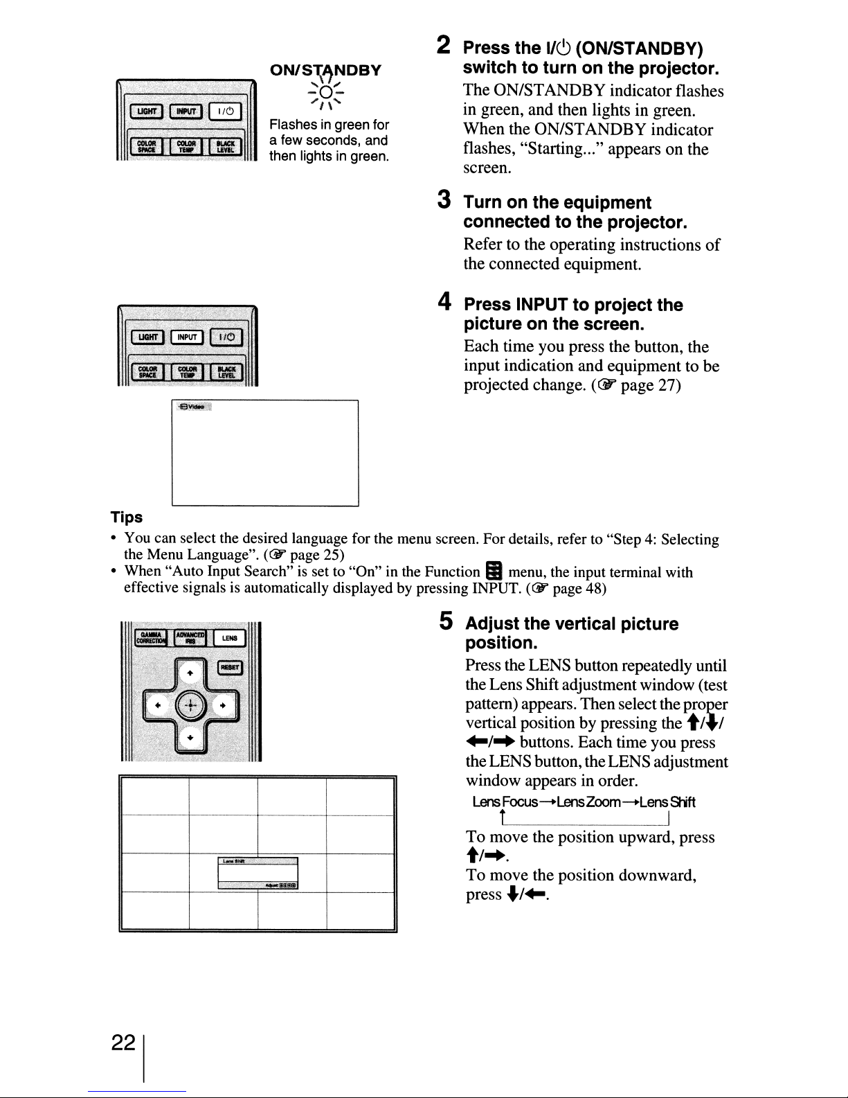
ON/S~"NDBY
~O~
"1\'
Flashes in green for
a few seconds, and
then lights in green.
2 Press the
switch to turn on the projector.
The
ON/STANDBY indicator flashes
in green, and then lights in green.
When
flashes, "Starting..." appears
screen.
I/CJ
(ON/STANDBY)
the
ON/STANDBY
indicator
on
3 Turn on the equipment
connected to the projector.
Refer to the operating instructions
the connected equipment.
4 Press INPUT to project the
picture on the screen.
Each time you press the button, the
input indication and equipment to
projected change.
(&'
page 27)
the
of
be
Tips
• You can select the desired language for the menu screen. For details, refer to "Step4:Selecting
(CY'
the Menu Language".
• When "Auto Input Search" is set to "On" in the Function
is
effective signals
automatically displayed by pressing INPUT.
page 25)
II
menu, the input terminal with
(CY'
page 48)
5 Adjust the vertical picture
position.
Press the LENS button repeatedly until
the Lens Shiftadjustmentwindow (test
'--
I I
.-
pattern) appears. Thenselectthe
vertical position
+-/
..
buttons. Each time you press
theLENS button, theLENSadjustment
window appears in order.
Lens
Focus-LensZoom-Lens SIift
by
pressing the t/+/
t I
To
move the position upward, press
t/
...
To
move the position downward,
..
press
/+-.
proJ2er
22

Tip
When "Lens Control" is set to
picture position.
When "Test Pattern" is set to
(Gr
page 49)
The picture moves up by a maximumof65%ofthe screen size from the centerofthe lens.
65%
1
screen
height
(Gr
page 50)
120"
971
---
mm (38
""~,
-----
1
I
t-
I
I
I
I
I
I
I
I
i
I
I
I
L
"Off'
"Off'
1/
4
100"
809 mm
;
....~.....
i
--
on the Installation
on the Function
Side view
inches)
(31
7/
inches)
8
80"
647 mm (25
>,,,,,;-
------
-----
center of lens
~
menu, you cannot adjust the vertical
II
menu, the test patternisnot displayed.
1/
inches)
2
--------
--
--
(When using the 16:9 screen. For
more details, see page 15.)
Tip
You can also adjust the horizontal positionofthe lens. For detailed information, see "Making Fine
Adjustments to the Horizontal Picture Position" on page 73.
Picture position when the picture is
moved upward atthe maximum
6 Adjust the picture size.
Press the LENS button repeatedly
until the Lens Zoom adjustment
window (test pattern) appears. Then
adjust the sizeofthe picture by
pressing the t/-J/+-I
To
make thepicture larger, press
To make the picture smaller, press "I+-.
I
...
buttons.
t/
...
23
Tip
When "Lens Control" is set to
(<Ti'
and the focus.
When "Test Pattern" is set to
(<Ti'
page 49)
page 50)
~IMIJ
I I
"Off'
on the Installation~menu, you cannot adjust the picture size
"Off'
on the Function
!
I
I
I
I
!
II
menu, the test pattern is not displayed.
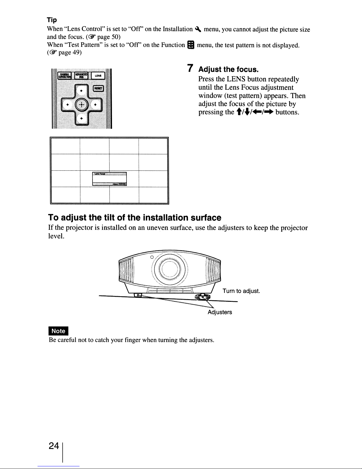
7 Adjust the focus.
Press the LENS button repeatedly
until the Lens Focus adjustment
window (test pattern) appears. Then
adjust the focus
pressing the
of
t/J/
the picture by
..
I-+
buttons.
To adjust the tilt of the installation surface
If
the projector is installed on an uneven surface, use the adjusters to keep the projector
level.
___
S;~~~~~~5~i~~T~ur~n
Adjusters
to
adjust.
..
Be careful not to catch your finger when turning the adjusters.
24
Step
4:
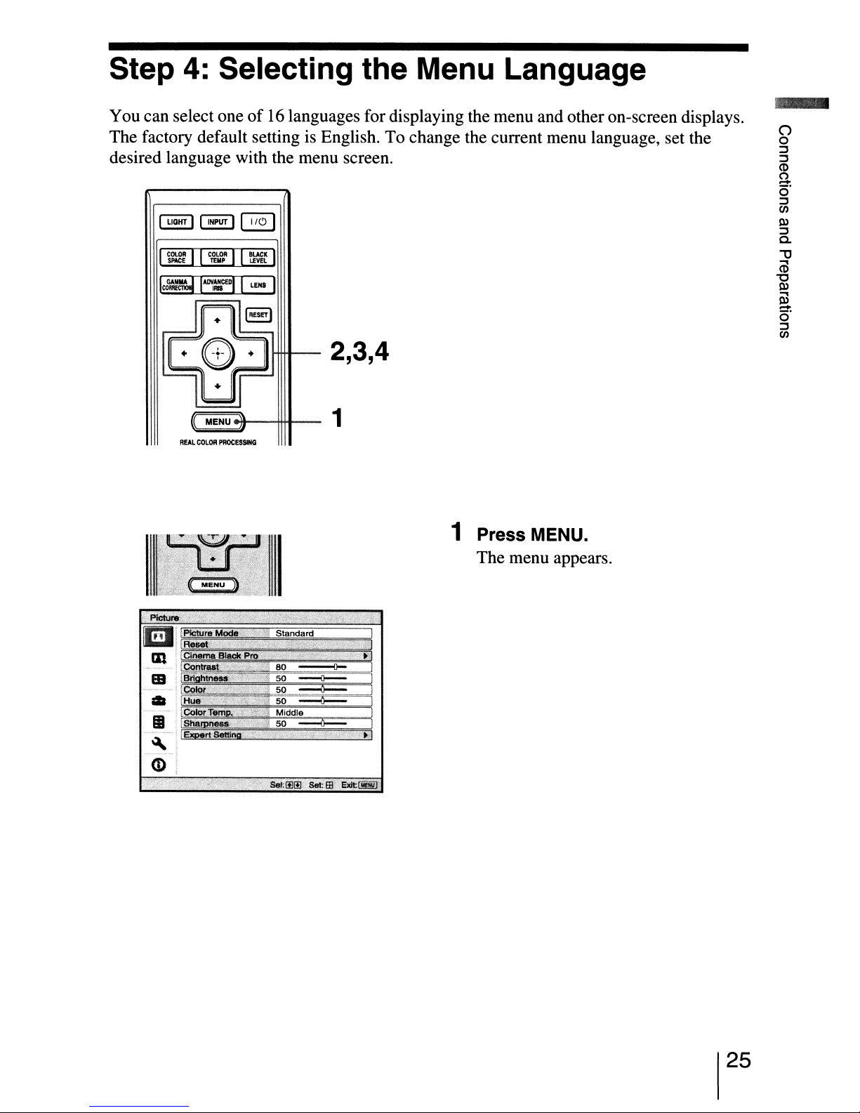
Selecting the Menu Language
You can select oneof16
The factory default setting is English. To change the current menu language, set the
desired language with the menu screen.
~
~
I
GAIIIlAC;;;U_lNCEDO
COllIE
111I
languages for displaying the menu and otheron-screen displays.
L£NI I
2,3,4
R£AL
MENU
COLOfl
PllOCESSING
1
~!
'-'1
till
m'
•
(I
~
CD
1 Press MENU.
The menu appears.
25
 Loading...