

Sony VPL-VW50 User Manual
Video Projector
Operating Instructions
2-887-661-11 (1)
VPL-VW50
© 2006 Sony Corporation
WARNING
To reduce the risk of fire or electric
shock, do not expose this apparatus
to rain or moisture.
To avoid electrical shock, do not
open the cabinet. Refer servicing to
qualified personnel only.
This symbol is intended to
alert the user to the presence
of uninsulated “dangerous
voltage” within the
product’s enclosure that may
be of sufficient magnitude to
constitute a risk of electric
shock to persons.
This symbol is intended to
alert the user to the presence
of important operating and
maintenance (servicing)
instructions in the literature
accompanying the
appliance.
For customers in the USA
If you have any questions about this product,
you may call:
Sony Customer Information Service Center
1-800-222-7669 or http://www.sony.com/
The number below is for FCC related
matters only.
Declaration of Conformity
Trade Name: SONY
Model No.: VPL-VW50
Responsible Party: Sony Electronics Inc.
Address: 16530 Via Esprillo, San Diego, CA
92127 U.S.A.
Telephone Number: 858-942-2230
This device complies with Part 15 of the
FCC Rules. Operation is subject to the
following two conditions: (1) This device
may not cause harmful interference, and (2)
this device must accept any interference
received, including interference that may
cause undesired operation.
This equipment has been tested and found to
comply with the limits for a Class B digital
device, pursuant to Part 15 of the FCC
Rules. These limits are designed to provide
reasonable protection against harmful
interference in a residential installation. This
equipment generates, uses, and can radiate
radio frequency energy and, if not installed
and used in accordance with the instructions,
may cause harmful interference to radio
communications. However, there is no
guarantee that interference will not occur in
a particular installation. If this equipment
does cause harmful interference to radio or
television reception, which can be
determined by turning the equipment off and
on, the user is encouraged to try to correct
the interference by one or more of the
following measures:
- Reorient or relocate the receiving antenna.
- Increase the separation between the
equipment and receiver.
- Connect the equipment into an outlet on a
circuit different from that to which the
receiver is connected.
- Consult the dealer or an experienced radio/
TV technician for help.
You are cautioned that any changes or
modifications not expressly approved in this
manual could void your authority to operate
this equipment.
2

Disposal of Used Lamp
This projector’s lamp contains mercury and
should be disposed of properly. Consult your
local authorities regarding safe disposal.
The material contained in this lamp are
similar to those of a fluorescent lamp, so you
should dispose of it in the same way.
For customers in the United States
This product contains mercury. Disposal of
this product may be regulated if sold in the
United States. For disposal or recycling
information, please contact your local
authorities or the
Electronics Industries Alliance (http://
www.eiae.org).
3
For customers in Canada
This Class B digital apparatus complies with
Canadian ICES-003.
Voor de klanten in Nederland
Gooi de batterij niet weg maar
lever deze in als klein chemisch
afval (KCA).
The socket-outlet should be installed near
the equipment and be easily accessible.
CAUTION
RISK OF EXPLOSION IF BATTERY IS
REPLACED BY AN INCORRECT
TYPE.
DISPOSED OF USED BATTERIES
ACCORDING TO THE LOCAL RULES.
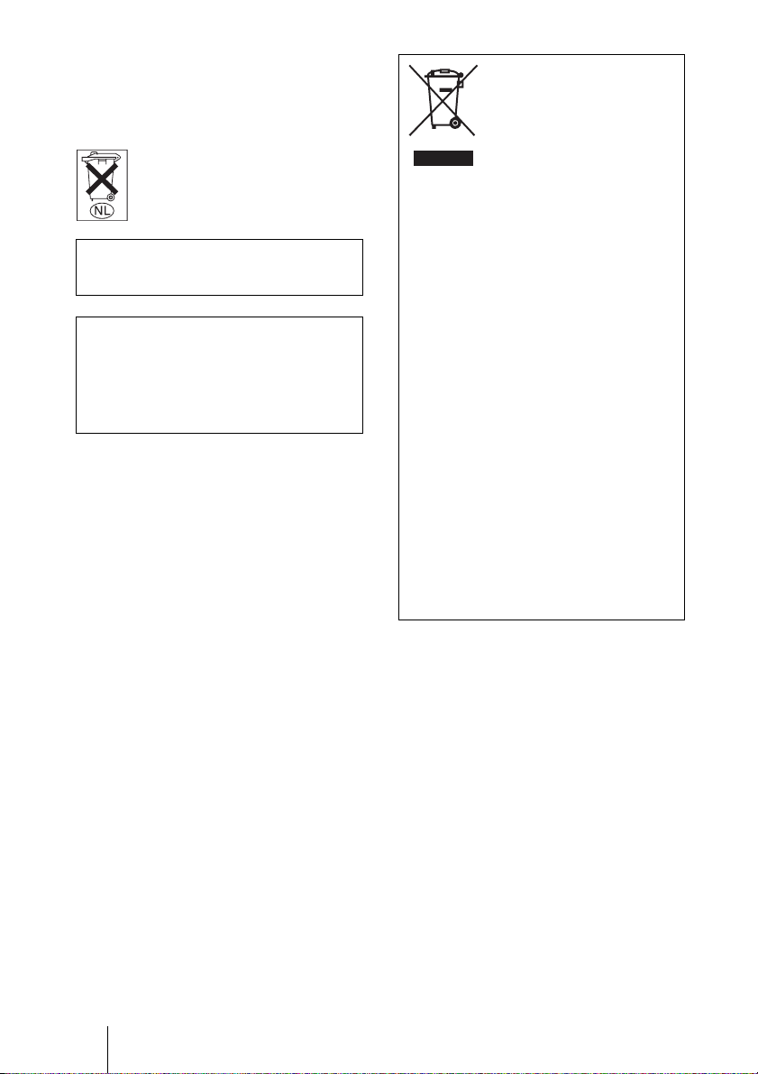
Disposal of Old Electrical &
Electronic Equipment (Applicable
in the European Union and other
European countries with separate
collection systems)
This symbol on the product or on its
packaging indicates that this product
shall not be treated as household waste.
Instead it shall be handed over to the
applicable collection point for the
recycling of electrical and electronic
equipment. By ensuring this product is
disposed of correctly, you will help
prevent potential negative consequences
for the environment and human health,
which could otherwise be caused by
inappropriate waste handling of this
product. The recycling of materials will
help to conserve natural resources. For
more detailed information about
recycling of this product, please contact
your local Civic Office, your household
waste disposal service or the shop where
you purchased the product.
4

Table of Contents
Precautions .........................................7
Location of Controls
Front/Right Side .................................8
Rear/Bottom .......................................9
Remote Control ................................10
Connections and
Preparations
Unpacking ........................................11
Step 1: Installing the Projector .........12
Before Setting Up the
Projector ..........................12
Positioning the Projector and a
screen ..............................14
Step 2: Connecting the Projector .....17
Connecting to a VCR .................17
Connecting to a Computer ..........20
Step 3: Adjusting the Picture
Position .............................................21
Step 4: Selecting the Menu
Language ..........................................25
Projecting
Projecting the Picture on the
Screen .............................................. 28
Turning Off the Power ............... 29
Selecting the Wide Screen Mode .... 30
Selecting the Picture Viewing
Mode ............................................... 32
Adjusting the Picture Quality .......... 33
Adjusting the Picture Using Real Color
Processing ........................................ 35
Using the Menus
Operation through the Menus .......... 37
Picture Menu ................................... 41
Advanced Picture Menu .................. 44
Screen Menu .................................... 45
Setup Menu ...................................... 47
Function Menu ................................. 49
Installation Menu ............................. 50
Information Menu ............................ 52
About the Preset Memory No. ... 52
5

Others
Troubleshooting ...............................53
Warning Indicators .....................55
Message Lists .............................56
Replacing the Lamp and the Air Filter
and cleaning the Ventilation holes
(intake) ............................................. 57
Cleaning the Air Filter .....................60
Specifications ................................... 61
Preset Signals .............................63
Input Signals and Adjustable/
Setting Items ................... 66
Ceiling Installation ........................... 68
When Using the PSS-H10 Projector
Suspension Support .........68
When Using the PSS-610 Projector
Suspension Support .........72
Making Fine Adjustments to the
Horizontal Picture Position .............. 75
Index ...............................................78
6

Precautions
On safety
• Check that the operating voltage of your
unit is identical with the voltage of your
local power supply.
• Should any liquid or solid object fall into
the cabinet, unplug the unit and have it
checked by qualified personnel before
operating it further.
• Unplug the unit from the wall outlet if it is
not to be used for several days.
• To disconnect the cord, pull it out by the
plug. Never pull the cord itself.
• The wall outlet should be near the unit and
easily accessible.
• The unit is not disconnected to the AC
power source (mains) as long as it is
connected to the wall outlet, even if the
unit itself has been turned off.
• Do not look into the lens while the lamp is
on.
• Do not place your hand or objects near the
ventilation holes. The air coming out is
hot.
On preventing internal heat buildup
After you turn off the power with the I/1
(ON/STANDBY) switch, do not disconnect
the unit from the wall outlet while the
cooling fan is still running.
Caution
The projector is equipped with ventilation
holes (intake) and ventilation holes
(exhaust). Do not block or place anything
near these holes, or internal heat build-up
may occur, causing picture degradation or
damage to the projector.
On repacking
Save the original shipping carton and
packing material; they will come in handy if
you ever have to ship your unit. For
maximum protection, repack your unit as it
was originally packed at the factory.
7
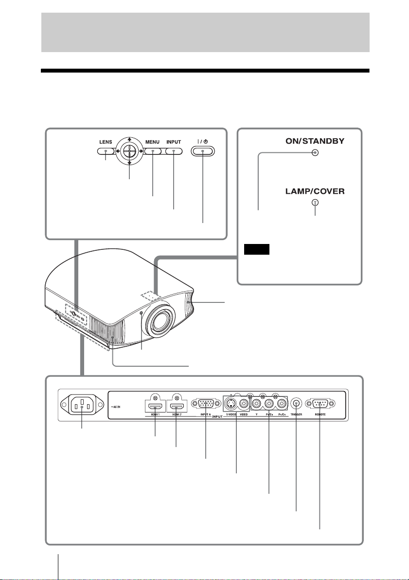
Location of Controls
Front/Right Side
You can use the buttons on the control panel with the same names as those on the remote
control to operate the projector.
LENS button
(1 page 22)
M/m/</, (arrow)/ENTER
button (1 page 37)
MENU button (1 page 37)
INPUT button (1 page 28)
?/1 (ON/STANDBY) switch (1 page 22)
ON/STANDBY
indicator
(1 page 21)
Note
While the ON/STANDBY indicator
lights in orange, the power saving
mode is on. (1 page 47)
Ventilation holes
(exhaust) (1 page 13)
LAMP/COVER
indicator
(1 page 55)
Remote control detector (1 page 21)
Ventilation holes (exhaust) (1 page 13)
- AC IN socket
HDMI1 connector (1 page 18)
HDMI2 connector (1 page 18)
INPUT A connector (1 page 20)
S VIDEO INPUT connector (mini DIN 4-pin)/VIDEO INPUT
connector (phono type) (1 page 19)
B/PB/CR/PR (phono type) (1 page 17)
Y/C
TRIGGER jack (mini jack)
Outputs a 12 V signal when the power is on
8
REMOTE connector
Connects to a computer, etc. for remote control
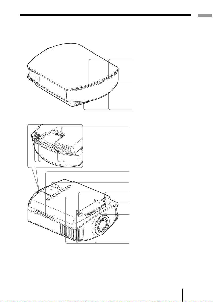
Rear/Bottom
Location of Controls
Ventilation holes (intake)
(1 page 13)
Remote control detector
(1 page 21)
Ventilation holes (intake)
(1 page 13)
Ventilation holes (intake)
Ventilation holes (intake)
Ventilation holes (intake)
Lamp cover
Adjusters
Filter holder
Ventilation holes (intake)
Projector suspension
support attaching hole
9
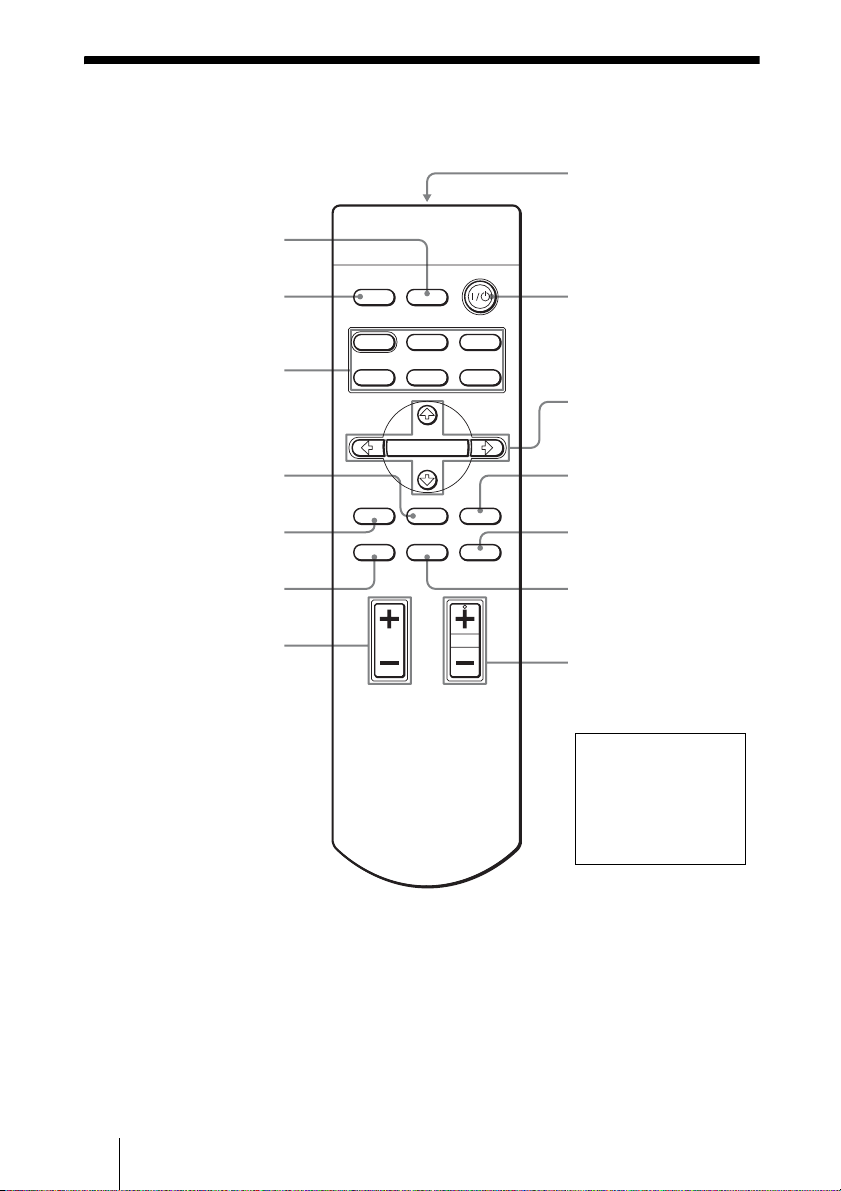
Remote Control
INPUT button
(1 page 28)
Infrared transmitter
Illuminates the buttons on
LIGHT button
the remote control.
PICTURE MODE
buttons (1 page 32)
ADJ PIC button
(1 page 33)
LENS button
(1 page 22)
WIDE MODE button
(1 page 30)
BRIGHT +/– button
(1 page 33)
INPUTLIGHT
STANDARD
USER 2
ENTER
ADJ PIC
RCP
CINEMA
USER 3USER 1
MENULENS
RESET
DYNAMIC
PICTURE MODE
WIDE MODE
REAL COLOR PROCESSING
BRIGHT CONTRAST
?/1 (ON/STANDBY)
switch (1 page 22)
M/m/</, (arrow)/
ENTER buttons
(1 page 37)
MENU button
(1 page 37)
RESET button
(1 page 37)
RCP button
(1 page 35)
CONTRAST +/– button
(1 page 33)
Tip
The CONTRAST +
button has a tactile dot.
Use it as a reference
when operating the
projector.
10
Connections and Preparations
This section describes how to install the projector and screen, how to connect the
equipment from which you want to project the picture, etc.
Unpacking
Check the carton to make sure it contains the following items:
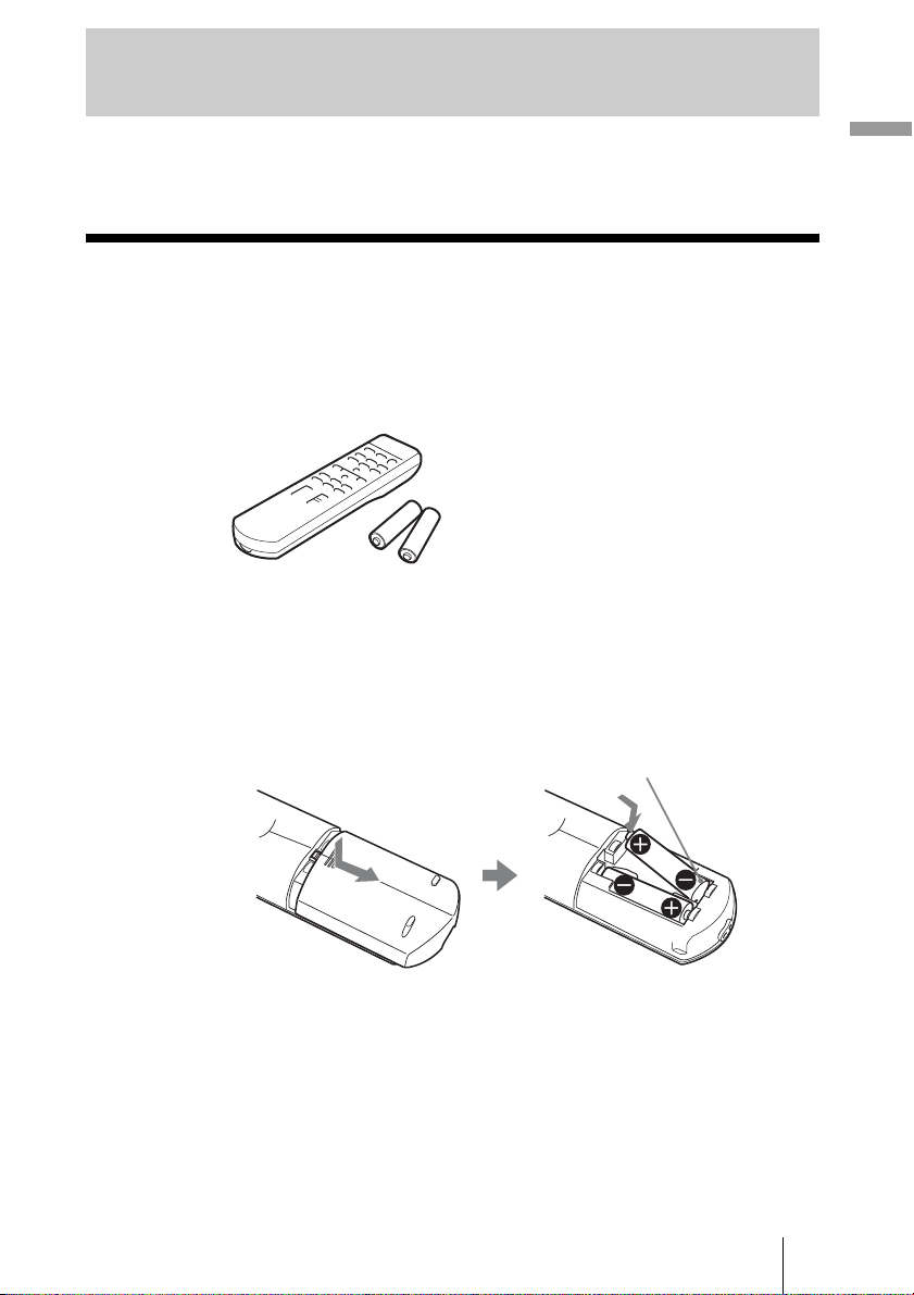
• Remote control (1) and
Size AA (R6) batteries (2)
• AC power cord (1)
• ImageDirector2 CD-ROM (1)
Inserting the batteries into the remote control
Insert the batteries E side first as shown in the illustration.
Inserting them forcibly or with the polarities reversed may cause
a short circuit and may generate heat.
• Lens cap (1)
When you have purchased the projector,
the lens cap was fitted onto the lens.
Remove this lens cap when you use the
projector.
• Operating Instructions (this manual)
Connections and Preparations
11
Step 1: Installing the Projector
The projector displays pictures output from
a VCR or other device.
The lens shift allows you to have broader
options for placing the projector and
viewing pictures easily.
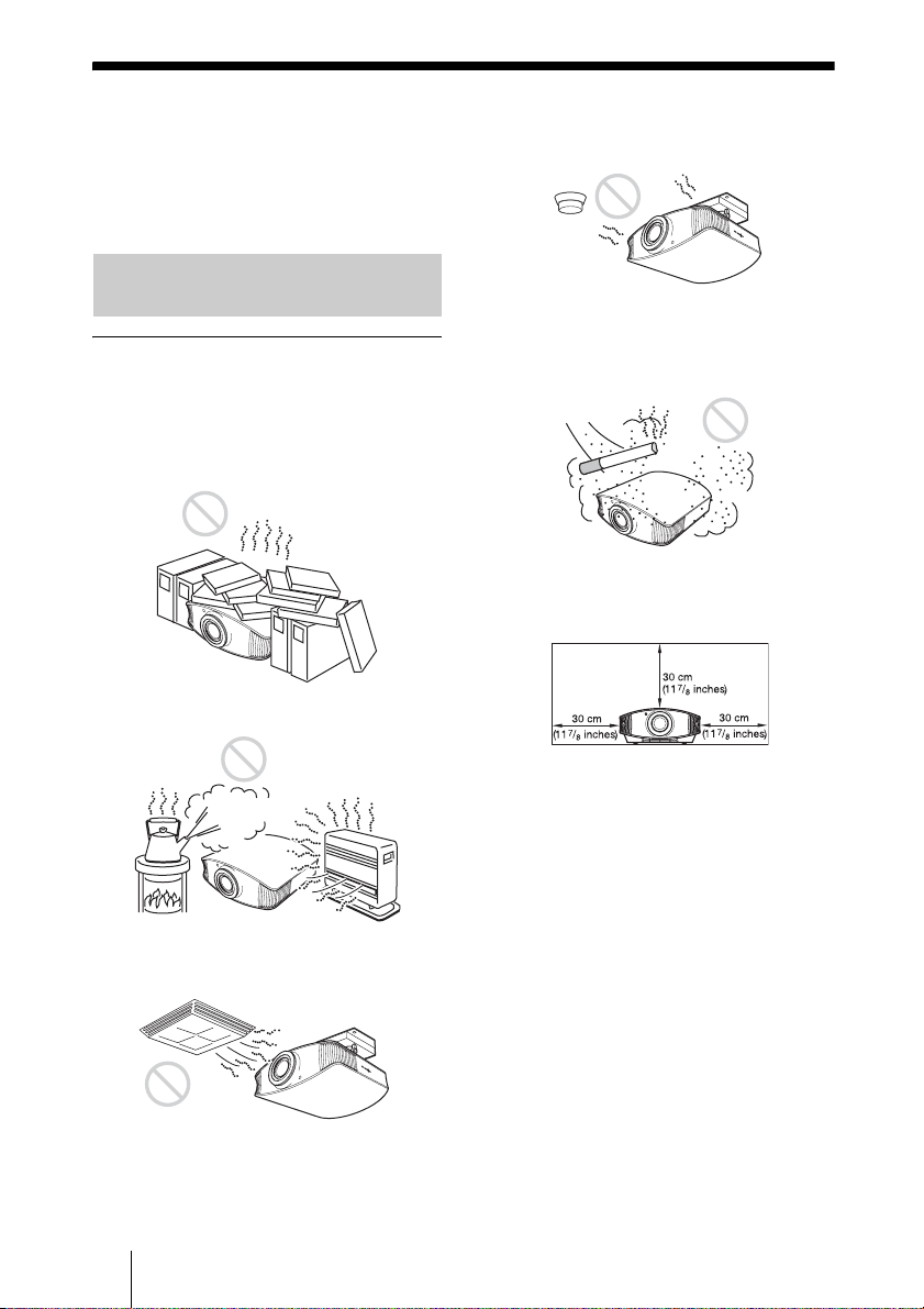
Before Setting Up the Projector
Unsuitable installation
Do not place the projector in the following
situations, which may cause malfunction
or damage to the projector.
Poorly ventilated location
Hot and humid
Near a heat or smoke sensor
Malfunction of the sensor may occur.
Very dusty and extremely smoky
locations
Allow at least 30 cm (11 7/8 inches)
between the projector and walls.
Locations subject to direct cool or
warm air from an air-conditioner
Installing the projector in such a location
may cause a malfunction of the unit due to
moisture condensation or rise in
temperature.
12
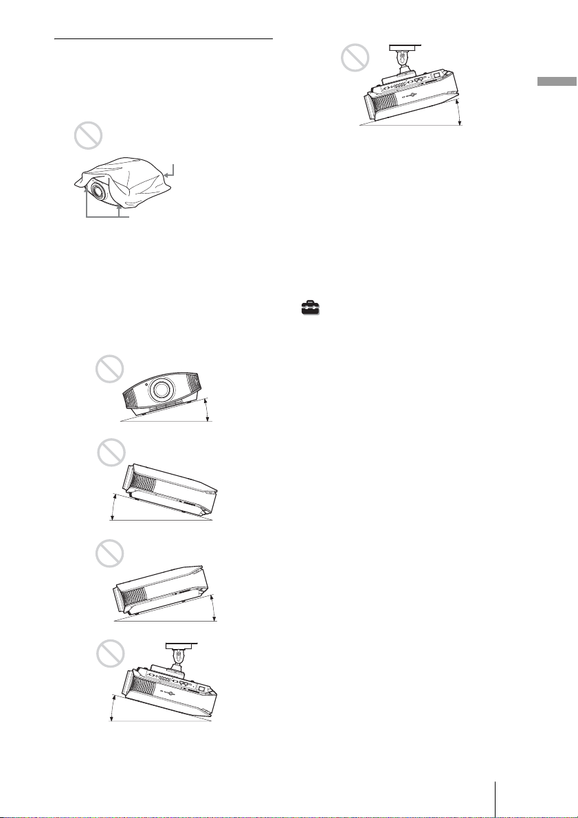
Improper use
Do not do any of the following while using
the projector.
Blocking the ventilation holes.
Connections and Preparations
15° or more
Ventilation holes
(intake)
Ventilation holes
(exhaust)
Tip
For details on the location of the ventilation
holes (intake or exhaust), see “Location of
Controls” on pages 8 to 9.
Tilting front/rear and left/right
15° or more
15° or more
Avoid using the projector tilted at an angle
of more than 15 degrees.
Do not install the projector anywhere other
than on a level surface or on the ceiling.
Failing to set this mode when using the
projector at high altitudes may result in
uneven color uniformity and reducing the
reliability of the effects of the lamp.
When installing the unit at altitudes
When using the projector at an altitude of 1,500
m or higher, set “Cooling Setting” in the Setup
menu to “High” (1 page 47). Failing to
set this mode when using the projector at high
altitudes could have adverse effects, such as
reducing the reliability of certain components.
15° or more
15° or more
13
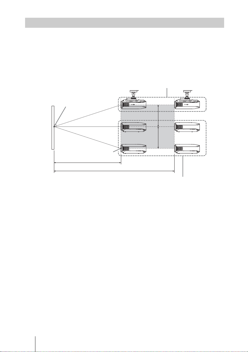
Positioning the Projector and a screen
The installation distance between the projector and a screen varies depending on the size
of the screen.
1 Determine the installation position of the projector and screen.
You can obtain a good quality picture if you position the projector with the center of
the lens within the areas indicated in the gray areas in the illustration. Use the values
a, b and c in the table on page 15 as a guide.
Ceiling installation
Center of the screen
c
c
Center of projector’s
lens
a
b
Floor installation
a: Minimum projection distance between the screen and the center of the projector’s
lens
b: Maximum projection distance between the screen and the center of the projector’s
lens
c: Vertical distance between the center of the screen and the center of the projector’s
lens when using the maximum upper vertical lens shift feature.
For installation of the projector on a ceiling, see “Ceiling Installation.” (1 page 68)
For details on the lens shift feature, see “Step 3: Adjusting the Picture Position.”
(1 page 21)
14
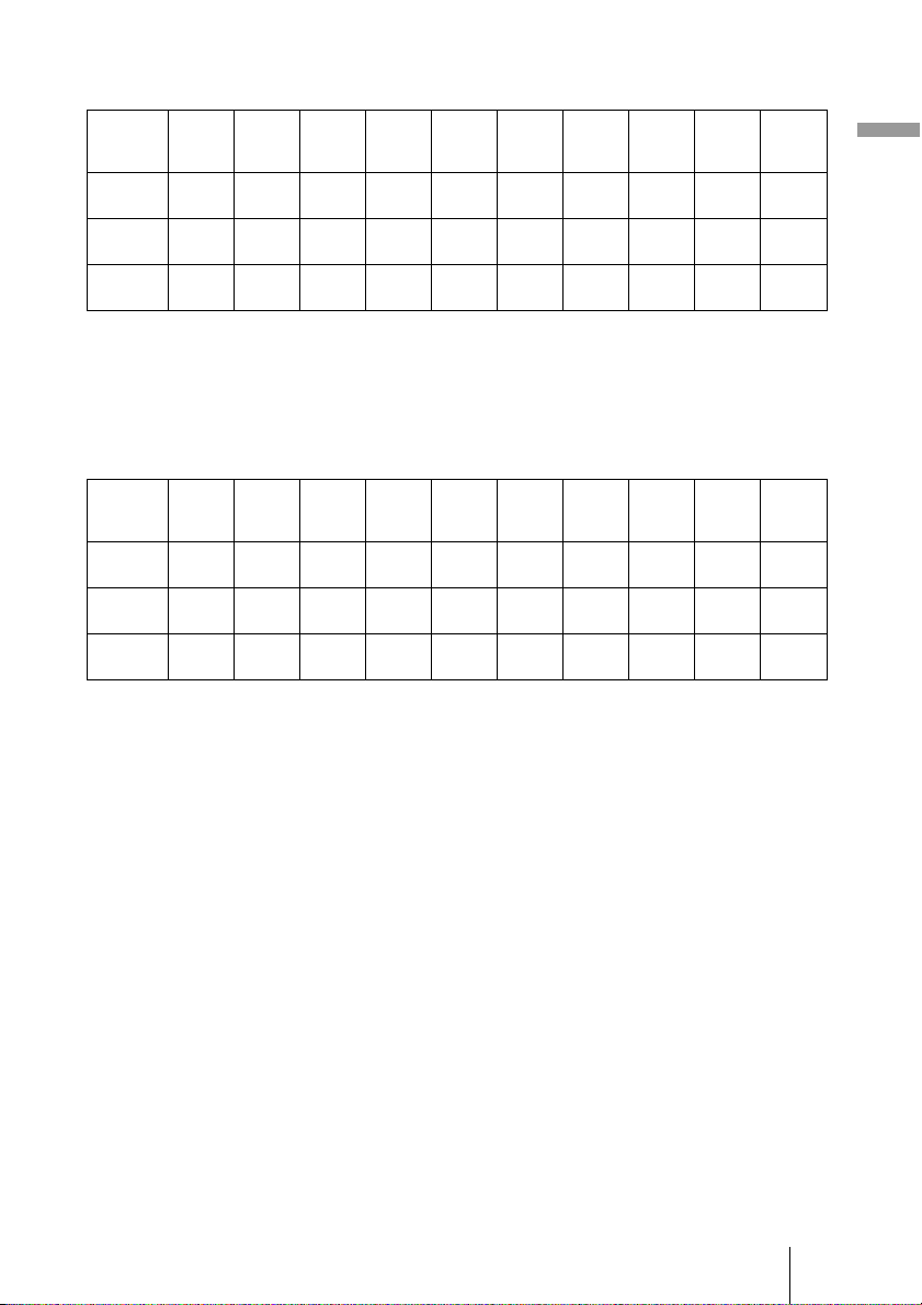
When using the 16:9 aspect ratio screen
Unit: mm (inches)
Screen
size
(inches)
a
(minimum)
b
(maximum)
c
To calculate the installation measurements (SS: Screen Size)
a (minimum) = 31.5 (1
b (maximum) = 53.8 (2
c = 8.0876 (
40 60 80 100 120 150 180 200 250 300
1212
(47
2105
(82
324
(12
3
/4)
7
/8)
7
/8)
11
/32) × SS
1842
2472
(72 5/8)
(97 3/8)
3181
4257
(125 1/4)
(167 5/8)
485
647
(19 1/8)
(25 1/2)
1
/4) × SS – 48.2 (1 15/16)
1
/8) × SS – 46.9 (1 7/8)
3102
(122 1/4)
5333
(210)
809
(31 7/8)
3732
(147)
6409
(252 3/8)
971
(38 1/4)
4677
(184 1/4)
8023
(315 7/8)
1213
(47 7/8)
5622
(221 3/8)
9637
(379 1/2)
1456
(57 3/8)
6252
(246 1/4)
10713
(421 7/8)
1618
(63 3/4)
7827
(308 1/4)
13403
(527 5/8)
2022
(79 5/8)
When using the 4:3 aspect ratio screen (projecting a 4:3 picture)
Unit: mm (inches)
Screen
size
(inches)
a
(minimum)
b
(maximum)
c
To calculate the installation measurements (SS: Screen Size)
a (minimum) = 38.551 (1
b (maximum) = 65.842 (2
c = 9.8979 (
40 60 80 100 120 150 180 200 250 300
1494
(58
2587
(101
396
(15
7
/8)
7
/8)
5
/8)
13
/32) × SS
2265
3036
(89 1/4)
(119 5/8)
3904
5220
(153 3/4)
(205 5/8)
594
792
(23 1/2)
(31 1/4)
9
/16) × SS – 48.2 (1 15/16)
5
/8) × SS – 46.9 (1 7/8)
3807
(150)
6537
(257 3/8)
990
(39)
4578
(180 1/4)
7854
(309 1/4)
1188
(46 7/8)
5734
(225 3/4)
9829
(387)
1485
(58 1/2)
6891
(271 3/8)
11805
(464 7/8)
1782
(70 1/4)
7662
(301 3/4)
13122
(516 5/8)
1980
(78)
9590
(377 5/8)
16414
(646 1/4)
2474
(97 1/2)
9402
(370 1/4)
16093
(633 5/8)
2426
(95 5/8)
11517
(453 1/2)
19706
(775 7/8)
2969
(117)
Connections and Preparations
15
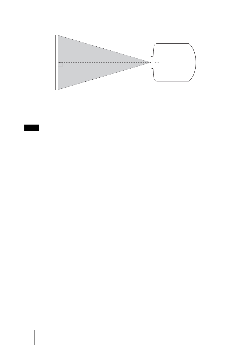
2 Position the projector so that the lens is parallel to the screen.
Top view
Screen
3 Project an image on the screen and adjust the picture so that it fits the
screen. (1 page 21)
To project an image, connect video equipment to the projector. (1 page 17)
Note
When using a screen with an uneven surface, stripes pattern may rarely appear on the screen
depending on the distance between the screen and the projector or the zooming magnifications. This
is not a malfunction of the projector.
16
Step 2: Connecting the Projector
When making connections, be sure to do the following:
• Turn off all equipment before making any connections.
• Use the proper cables for each connection.
• Insert the cable plugs properly; poor connection at the plugs may cause a malfunction or
poor picture quality. When pulling out a cable, be sure to pull it out from the plug, not
the cable itself.
• Refer to the operating instructions of the connected equipment.
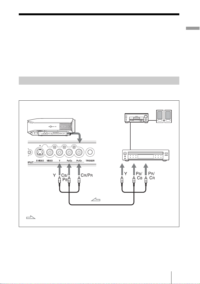
Connecting to a VCR
To connect to a DVD player/recorder, Blu-ray Disc player or digital tuner
equipped with component video connectors
AV amplifier
Right side of the projector
DVD player/recorder, HDD
recorder, Blu-ray Disc
player, digital tuner, etc.,
with component video
connectors
Speakers
Connections and Preparations
: Video signal flow
Component video cable (not supplied)
17
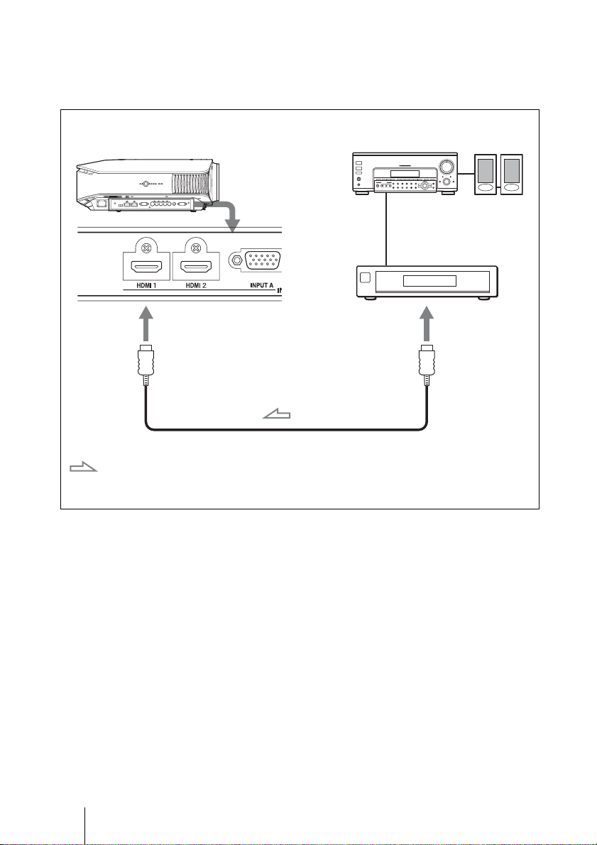
To connect to a DVD player/recorder and Blu-ray Disc player
equipped with HDMI output
You can enjoy better picture quality by connecting a DVD player/recorder and Blu-ray
Disc player equipped with HDMI output to the HDMI input of the projector.
Right side of the projector
: Video signal flow
AV amplifier
DVD player/recorder and
Blu-ray Disc player, etc.,
with the HDMI output
HDMI cable (not supplied)
When using an optional HDMI cable, be sure to use
a cable with the HDMI logo.
Speakers
to HDMI output
............................................................................................................................................................
HDMI, HDMI logo and High-Definition Multimedia Interface are trademarks or registered
trademarks of HDMI Licensing LLC. This HDMI connector conforms to Ver. 1.2a.
18
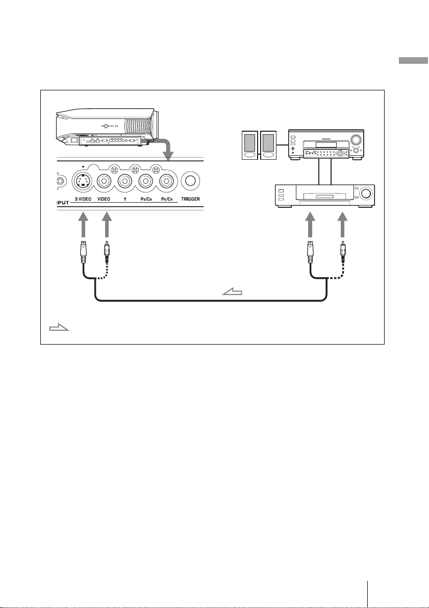
To connect to a VCR equipped with the S video connector or
video connector
You can connect a DVD player/recorder, hard disk video recorder, VCR or laser disk
player, which is not equipped with component video connectors. See also the instruction
manual of each equipment.
Right side of the projector
Connections and Preparations
Speakers
Video equipment
to S video or
video output
S video or video cable (not supplied)
: Video signal flow
Tip
If you do not know to which connector you should connect the cable, S VIDEO INPUT (S video
input connector) or VIDEO INPUT (video input connector), connect it to S VIDEO to enjoy better
picture quality.
If the equipment to be connected has no S video connector, connect the cable to the video output.
AV amplifier
19
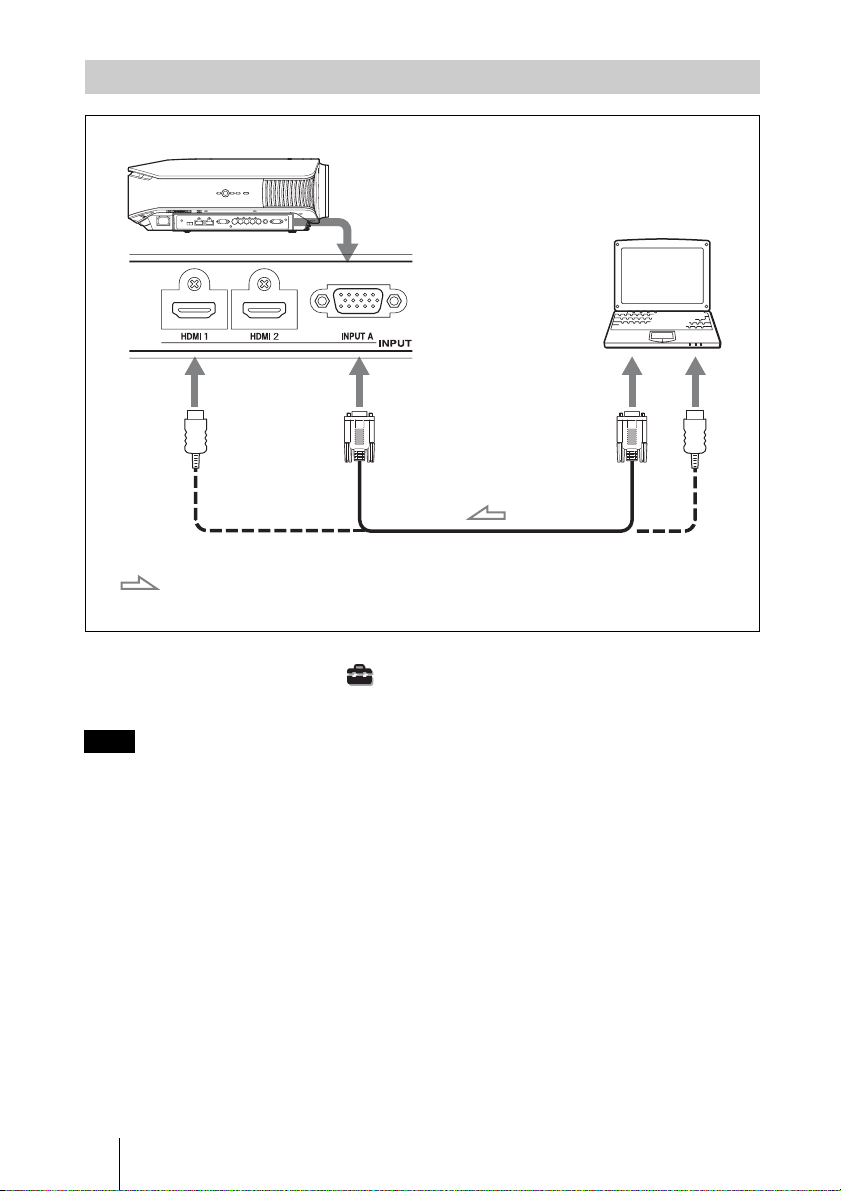
Connecting to a Computer
Right side of the projector
HD-Dsub15 pin cable (optional) or HDMI cable (optional)
Computer
to monitor output
: Video signal flow
When using an optional HDMI cable, be sure to use
a cable with the HDMI logo.
Tip
Set “Input-A Signal Sel.” in the Setup menu to “Auto” or “Computer.” If the input signal does
not appear properly, set it to “Computer.” (1 page 48, 56)
Note
If you set your computer, such as a notebook type, to output the signal to both computer’s display
and this equipment, the picture of the equipment may not appear properly. Set your computer to
output the signal to only the external monitor.
For details, refer to the computer’s operating instructions supplied with your computer.
20
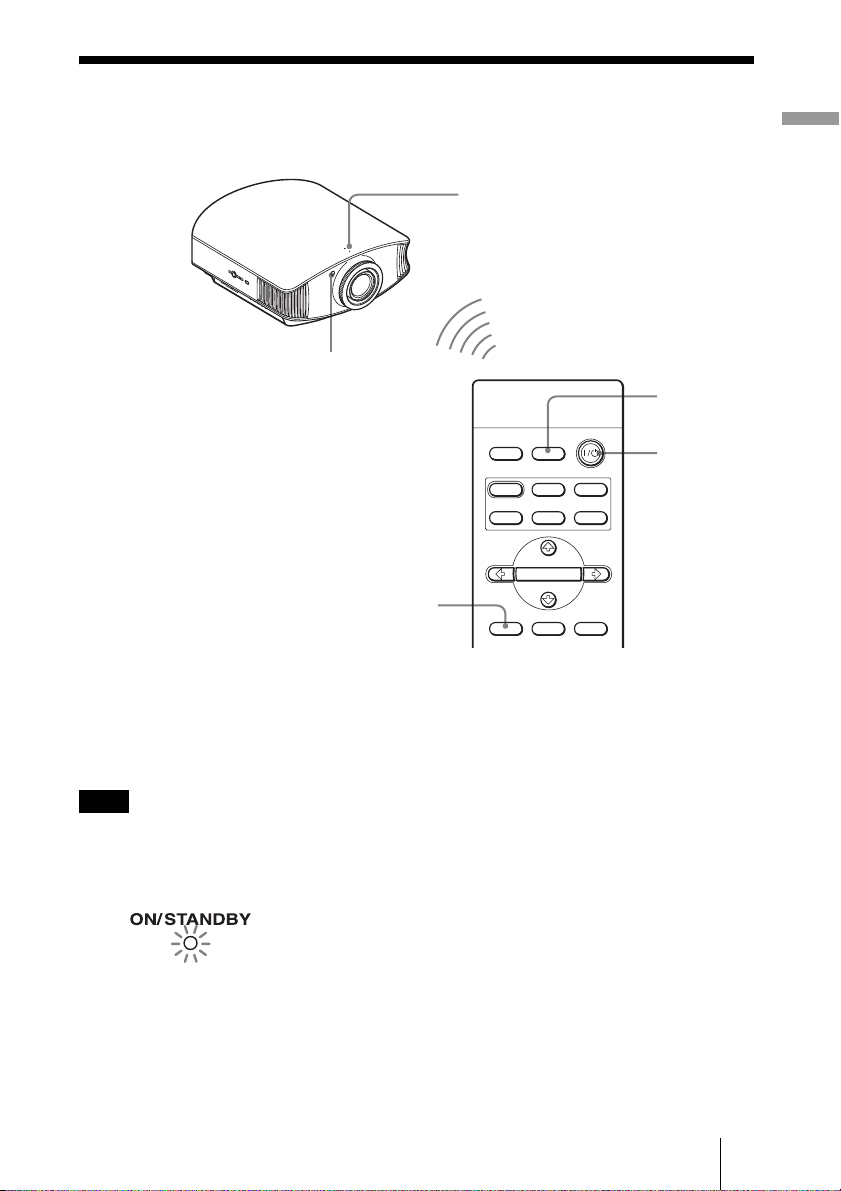
Step 3: Adjusting the Picture Position
Project an image on the screen and then adjust the picture position.
ON/STANDBY indicator
1
Remote control detector
4
INPUTLIGHT
STANDARD
PICTURE MODE
USER 2
ENTER
ADJ PIC
CINEMA
USER 3USER 1
MENULENS
DYNA MIC
5,6,7
Tip
?/1 (ON/STANDBY), INPUT, LENS, MENU, and M/m/</,/ENTER (joystick) buttons on
The
the side panel of the projector function the same as those on the remote control.
2
Connections and Preparations
Note
Depending on the installation location of the projector, you may not control it with the remote
control. In this case, point the remote control to the screen instead of the projector.
1 After connecting the AC cord to
the equipment, plug the AC
Lights in red.
code into a wall outlet.
The ON/STANDBY indicator lights
in red and the projector goes into
standby mode.
21
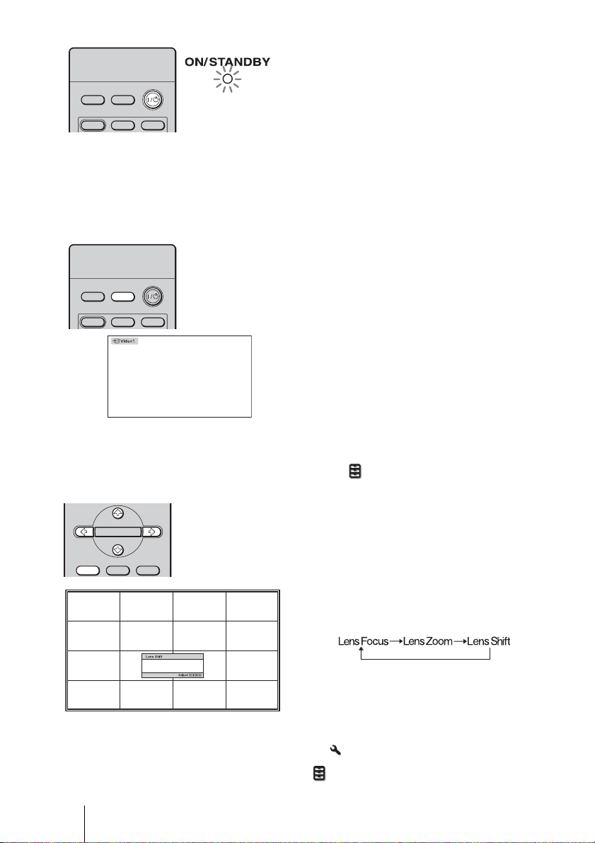
2 Press the ?/1 (ON/STANDBY)
switch to turn on the projector.
The ON/STANDBY indicator flashes
in green, and then lights in green.
When the ON/STANDBY indicator
flashes, “Starting...” appears on the
screen.
DYNA MIC
INPUTLIGHT
STANDARD
Flashes in green for
a few seconds, and
CINEMA
then lights in green.
3 Turn on the equipment
connected to the projector.
Refer to the operating instructions of
the connected equipment.
4 Press INPUT to project the
picture on the screen.
Each time you press the button, the
INPUTLIGHT
STANDARD
DYNA MIC
CINEMA
Tips
• You can select the desired language for the menu screen. For details, refer to “Step 4: Selecting
the Menu Language”. (1 page 25)
• When “Auto Input Search” is set to “On” in the Function menu, the input terminal with
effective signals is automatically displayed by pressing INPUT. (1 page 49)
input indication and equipment to be
projected change. (1 page 28)
5 Adjust the vertical picture
ENTER
ADJ PIC
MENULENS
position.
Press the LENS button repeatedly until
the Lens Shift adjustment window (test
pattern) appears. Then select the proper
vertical position by pressing the M/m/
</, buttons. Each time you press
the LENS button, the LENS adjustment
window appears in order.
To move the position upward, press
M/,.
To move the position downward,
m/<.
press
Tip
When “Lens Control” is set to “Off” on the Installation
picture position. (1 page 50)
When “Test Pattern” is set to “Off” on the Function menu, the test pattern is not displayed.
(1 page 49)
22
menu, you cannot adjust the vertical
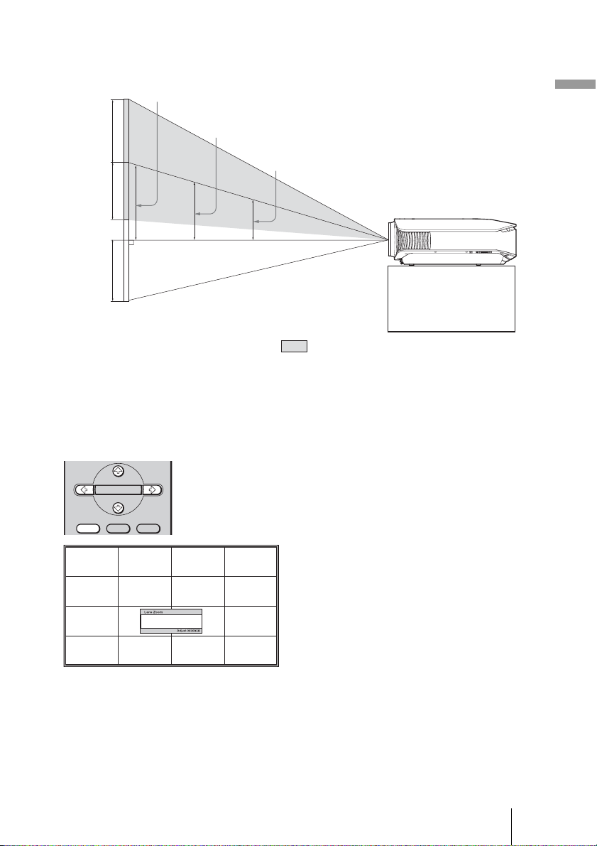
The picture moves up by a maximum of 65% of the screen size from the center of the lens.
Side view
120”
971 mm (38
1
/4 inches)
100”
809 mm (31
7
/8 inches)
80”
647 mm (25
1
/2 inches)
Connections and Preparations
(When using the 16:9 screen. For
more details, see page 15.)
: Picture position when the picture is
moved upward at the maximum
Tip
You can also adjust the horizontal position of the lens. For detailed information, see “Making Fine
Adjustments to the Horizontal Picture Position” on page 75.
6 Adjust the picture size.
ENTER
ADJ PIC
MENULENS
Press the LENS button repeatedly
until the Lens Zoom adjustment
window (test pattern) appears. Then
adjust the size of the picture by
pressing the M/m/</, buttons.
To make the picture larger, press
To make the picture smaller, press
M/,.
m/<.
23
Tip
When “Lens Control” is set to “Off” on the Installation menu, you cannot adjust the picture size
and the focus. (1 page 50)
When “Test Pattern” is set to “Off” on the Function menu, the test pattern is not displayed.
(1 page 49)
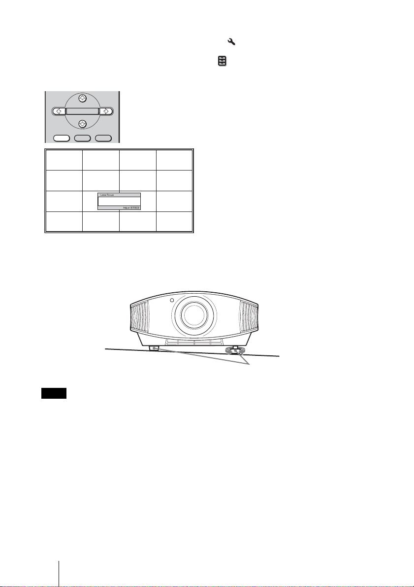
7 Adjust the focus.
ENTER
ADJ PIC
MENULENS
To adjust the tilt of the installation surface
If the projector is installed on an uneven surface, use the adjusters to keep the projector
level.
Press the LENS button repeatedly
until the Lens Focus adjustment
window (test pattern) appears. Then
adjust the focus of the picture by
pressing the M/m/</, buttons.
Note
Be careful not to catch your finger when turning the adjusters.
24
Turn to adjust.
Adjusters
 Loading...