

Sony VPL-VW12HT Operating Instruction
VPL-VW12HT
4-090-454-11(1)
Video Pr ojector
Operating Instructions
Mode d’emploi
Manual de instrucciones
GB
FR
ES
VPL-VW12HT
2002 Sony Corporation
WARNING
To prevent fire or shock hazard, do not
expose the unit to rain or moisture.
To avoid electrical shock, do not open the
cabinet. Refer servicing to qualified
personnel only.
This symbol is intended to alert the
user to the presence of uninsulated
“dangerous voltage” within the
product’s enclosure that may be of
sufficient magnitude to constitute a risk
of electric shock to persons.
This symbol is intended to alert the
user to the presence of important
operating and maintenance (servicing)
instructions in the literature
accompanying the appliance.
For the customers in the USA
If you have any questions about this product, you may
contact: Sony Electronics Inc.
Attn: Business Information Center (BIC) 12451 Gateway
Boulevard Ft. Myers, Florida 33913
Telephone No.: 800-686-7669
WARNING
This equipment has been tested and found to comply with
the limits for a Class B digital device, pursuant to Part 15 of
the FCC Rules. These limits are designed to provide
reasonable protection against harmful interference in a
residential installation. This equipment generates, uses, and
can radiate radio frequency energy and, if not installed and
used in accordance with the instructions, may cause harmful
interference to radio communications. However, there is no
guarantee that interference will not occur in a particular
installation. If this equipment does cause harmful
interference to radio or television reception which can be
determined by turning the equipment off and on, the user is
encouraged to try to correct the interference by one or more
of the following measures:
– Reorient or relocate the receiving antenna.
– Increase the separation between the equipment and
receiver.
– Connect the equipment into an outlet on a circuit different
from that to which the receiver is connected.
– Consult the dealer or an experienced radio/TV technician
for help.
You are cautioned that any changes or modifications not
expressly approved in this manual could void your authority
to operate this equipment.
For the customers in Europe
This product with the CE marking complies with both the
EMC Directive (89/336/EEC) and the Low Voltage Directive
(73/23/EEC) issued by the Commission of the European
Community.
Compliance with these directives implies conformity to the
following European standards:
• EN60950: Product Safety
• EN55103-1: Electromagnetic Interference (Emission)
• EN55103-2: Electromagnetic Susceptibility (Immunity)
This product is intended for use in the following
Electromagnetic Environment(s):
E1 (residential), E2 (commercial and light industrial), E3
(urban outdoors) and E4 (controlled EMC environment, ex.
TV studio).
The number below is for FCC related matters only.
Declaration of Conformity
Trade Name: SONY
Model: VPL-VW12HT
Responsible Party: Sony Electronics Inc.
Address: 680 Kinderkamack Road,
Oradell NJ 07649 U.S.A.
Telephone No.: 201-930-6972
2 (GB)
For the customers in Canada
This Class B digital apparatus complies with Canadian
ICES-003.
For the customers in the United Kingdom
WARNING
THIS APPARATUS MUST BE EARTHED
IMPORTANT
The wires in this mains lead are coloured in accordance with
the following code:
Green-and-Yellow: Earth
Blue: Neutral
Brown: Live
As the colours of the wires in the mains lead of this
apparatus may not correspond with the coloured markings
identifying the terminals in your plug proceed as follows:
The wire which is coloured green-and-yellow must be
connected to the terminal in the plug which is marked by the
letter E or by the safety earth symbol I or coloured green
or green-and-yellow.
The wire which is coloured blue must be connected to the
terminal which is marked with the letter N or coloured black.
The wire which is coloured brown must be connected to the
terminal which is marked with the letter L or coloured red.
GB
English
Voor de klanten in Nederland
Gooi de batterij niet weg maar lever deze in
als klein chemisch afval (KCA).
The socket-outlet should be installed near the equipment
and be easily accessible.
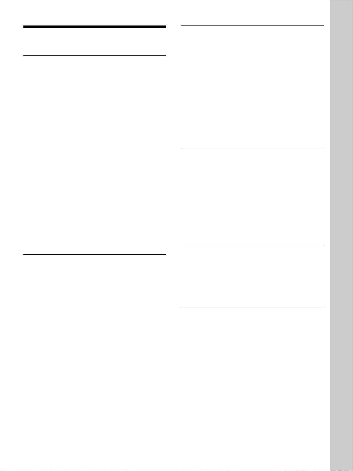
Warning on power connection
Use a proper power cord for your local power supply.
The United States, Continental UK, Ireland, Japan
Canada Europe Australia, New Zealand
Plug type VM0233 290B YP-12A COX-07 —
Female end VM0089 386A YC-13B COX-02 VM0310B YC-13
Cord type SJT SJT H05VV-F H05VV-F N13237/CO-228 VCTF
Rated Voltage & Current 10A/125V 10A/125V 10A/250V 10A/250V 10A/250V 7A/125V
Safety approval UL/CSA UL/CSA VDE VDE VDE DENANHOU
Cord length (max.) 4.5 m 4.5 m — — — —
.........................................................................................................................................................................................................
1)
YP332
1) Use the correct plug for your country.
3 (GB)

4 (GB)

Table of Contents
Overview
Setting Up and Projecting
Precautions ............................................................... 7 (GB)
Features..................................................................... 8 (GB)
Location and Function of Controls....................... 10 (GB)
Front/Left Side ....................................................... 10 (GB)
Rear/Right Side/Bottom......................................... 10 (GB)
Control Panel ......................................................... 12 (GB)
Connector Panel ..................................................... 13 (GB)
Remote Commander .............................................. 14 (GB)
Installing the Projector........................................... 16 (GB)
Connecting the Projector....................................... 16 (GB)
Connecting to a VCR/15k RGB/Component/
Progressive Component Equipment ................. 16 (GB)
Connecting to a Computer ..................................... 17 (GB)
Selecting the Menu Language............................... 18 (GB)
Projecting ................................................................ 19 (GB)
Adjustments and Settings Using the Menu
Using the Menu....................................................... 23 (GB)
The PICTURE CTRL Menu ..................................... 24 (GB)
The INPUT SETTING Menu .................................... 25 (GB)
The SET SETTING Menu ........................................ 30 (GB)
The INSTALL SETTING Menu ................................ 31 (GB)
Installation
Installation Example............................................... 32 (GB)
Floor Installation.................................................... 32 (GB)
Ceiling Installation................................................. 35 (GB)
Notes on Installation .............................................. 39 (GB)
Unsuitable Installation ........................................... 39 (GB)
Unsuitable Conditions for Use............................... 39 (GB)
5 (GB)

Maintenance
Other
Maintenance............................................................ 41 (GB)
Replacing the Lamp ............................................... 41 (GB)
Replacing the Air Filter! ........................................ 42 (GB)
Troubleshooting ..................................................... 43 (GB)
Specifications ......................................................... 46 (GB)
Index ........................................................................ 50 (GB)
6 (GB)
Precautions
Precautions
On safety
•Check that the operating voltage of your unit is
identical with the voltage of your local power
supply.
•Should any liquid or solid object fall into the cabinet,
unplug the unit and have it checked by qualified
personnel before operating it further.
•Unplug the unit from the wall outlet if it is not to be
used for several days.
•To disconnect the cord, pull it out by the plug. Never
pull the cord itself.
•The wall outlet should be near the unit and easily
accessible.
•The unit is not disconnected to the AC power source
(mains) as long as it is connected to the wall outlet,
even if the unit itself has been turned off.
•Do not look into the lens while the lamp is on.
•Do not place your hand or objects near the
ventilation holes — the air coming out is hot.
•Be careful not to catch your fingers with the
adjusters when you lift up the projector. Do not
push hard on the top of the projector with the
adjusters out.
On preventing internal heat build-up
After you turn off the power with the 1 key on the
1
Remote Commander or the I /
panel, do not disconnect the unit from the wall outlet
while the cooling fan is still running.
Do not block ventilation holes
The projector is equipped with ventilation holes
(intake) on the bottom and ventilation holes (exhaust)
on the front. Do not block or place anything near
these holes, or internal heat build-up may occur,
causing picture degradation or damage to the
projector.
key on the control
On cleaning
•To keep the cabinet looking new, periodically clean
it with a soft cloth. Stubborn stains may be removed
with a cloth lightly dampened with a mild detergent
solution. Never use strong solvents, such as thinner,
benzene, or abrasive cleansers, since these will
damage the cabinet.
•Avoid touching the lens. To remove dust on the lens,
use a soft dry cloth. Do not use a damp cloth,
detergent solution, or thinner.
Overview
On illumination
•To obtain the best picture, the front of the screen
should not be exposed to direct lighting or sunlight.
•Ceiling-mounted spot lighting is recommended. Use
a cover over fluorescent lamps to avoid lowering the
contrast ratio.
•Cover any windows that face the screen with opaque
draperies.
•It is desirable to install the projector in a room where
floor and walls are not of light-reflecting material. If
the floor and walls are of reflecting material, it is
recommended that the carpet and wall paper be
changed to a dark color.
On repacking
Save the original shipping carton and packing
material; they will come in handy if you ever have to
ship your unit. For maximum protection, repack your
unit as it was originally packed at the factory.
About the LCD projector
•The LCD projector is manufactured using highprecision technology. You may, however, see tiny
black points and/or bright points (red, blue, or green)
that continuously appear on the LCD projector. This
is a normal result of the manufacturing process and
does not indicate a malfunction.
•Air polluted by tobacco smoke, etc., may have a
negative effect on the projector.
Be sure to avoid tobacco smoke, etc., from directly
getting in to this unit.
Ventilate well when using this unit in a closed room.
7 (GB)
Features
Features
High brightness, high picture quality
•New, wide LCD panel
The newly developed high-resolution wide LCD
panel (1366 × 768 dots) provides higher uniformity
and reduced ghosts.
•High-contrast
Improvements in the LCD panel and the optical
system provide a high-contrast images.
•High-brightness – 1000 ANSI lumens
The LCD panel with its newly developed 200 W
UHP lamp, optical unit and lens achieves a high
level of brightness of as much as 1000 ANSI lumens
(16:9 projection), allowing for improved home
viewing.
•High-quality images
In addition to the new wide LCD panel, a variety of
functions are now available in the projector. These
include DRC-MF (Digital Reality Creation
Multifunction), Sony’s proprietary high-quality
image technology; CINE MOTION; 3-D Gamma
Correction, providing excellent uniformity; Cinema
Black Mode, a mode that reduces the black level
according to the input source/projection
environment; and 3-D YC Separation/DNR (NTSC),
a feature that reproduces a clear image without noise.
•Detection of clogs in the air filter
This projector uses an air filter which allows a
microcomputer to detect the presence of clogs in the
filter according to the environment where the unit is
used.
To detect clogs accurately, reset the air filter the
first time you use the projector, and every time
you replace the air filter.
For details, see “To reset the air filter” on page 42 (GB).
Wide Screen/DTV/High Definition
Television
•Wide Screen
This projector utilizes a 16:9 aspect ratio LCD panel,
allowing seven screen modes (ZOOM, FULL,
SUBTITLE, WIDE ZOOM, etc.) using all panel
pixels (1366 × 768).
It offers NORMAL THROUGH mode and FULL
THROUGH mode to reproduce a sharp image with
one-to-one mapping.
•DVD, DTV, High-Definition Television
The projector’s super-precise image exceeds 3.14
million pixels. It is also compatible with nextgeneration DTV (digital TV) and high-definition
television signals. Combined with a tuner or a
MUSE decoder (optional), you can enjoy DTV,
high-definition television, high-definition LD, etc.
High-adaptability in the home
environment
•Reduced noise
The exhaust opening at the front is connected to an
internal fan and air duct. This means the distance
from the fan to the exhaust opening is long,
significantly reducing fan noise.
•Flexible setup
The projection lens has a short focus (100 inches at
3.3 m (10.7 feet) with an aspect ratio of 16:9). The
digital keystone correction function allows
projection at a wide angle. The projector’s white
color goes with any color (ceilings, walls, etc.).
.........................................................................................................................................................................................................
1) This software cannot be used with the Macintosh operating system.
Video memory
The projector has a video memory function. The user
can store up to 6 settings (image quality, aspect,
temperature color, DRC-MF, etc.) according to the
input source. The user can directly recall any setting
from the Remote Commander.
Gamma correction
Using the gamma control software (“ImageDirector”)
provided with the projector, you can adjust R, G, and
B values independently.
For instructions on how to use the ImageDirector, see the
Operating Instructions provided on the CD-ROM that came
with the projector.
1)
8 (GB)

Multi scan compatibility
•Scan converter built-in
This projector has a built-in scan converter which
converts the input signal for a 1366 × 768 pixel
image.
•Compatible with 16:9 RGB
This projector is compatible with 16:9 aspect ratio
RGB signals.
•Input signals
The projector can accept the following video signals:
Composite, S-video, Component, Progressive
component, DTV (480i/p, 720p/1080i), HDTV, 15k
RGB, VGA, SVGA, XGA and SXGA.
1)
Features
•Compatible with six color systems
Any of the NTSC
3.58, PAL, SECAM, NTSC 4.43
2)
,
PAL-M, or PAL-N color systems can be selected
automatically or manually.
.......................................................................................
•VGA, SVGA, XGA and SXGA are registered trademarks
of the International Business Machines Corporation,
U.S.A.
• VESA is a registered trademark of the Video Electronics
Standards Association.
• IBM® and PC/AT are a trademark and a registered
trademark of the International Business Machines
Corporation, U.S.A.
•Macintosh is a registered trademark of Apple Computer,
Inc.
.........................................................................................................................................................................................................
1) Compatible with specified signals only.
2) NTSC4.43 is the color system used when playing back a video recorded in the NTSC format on an NTSC4.43 system VCR.
9 (GB)
Location and Function of Controls
Location and Function of
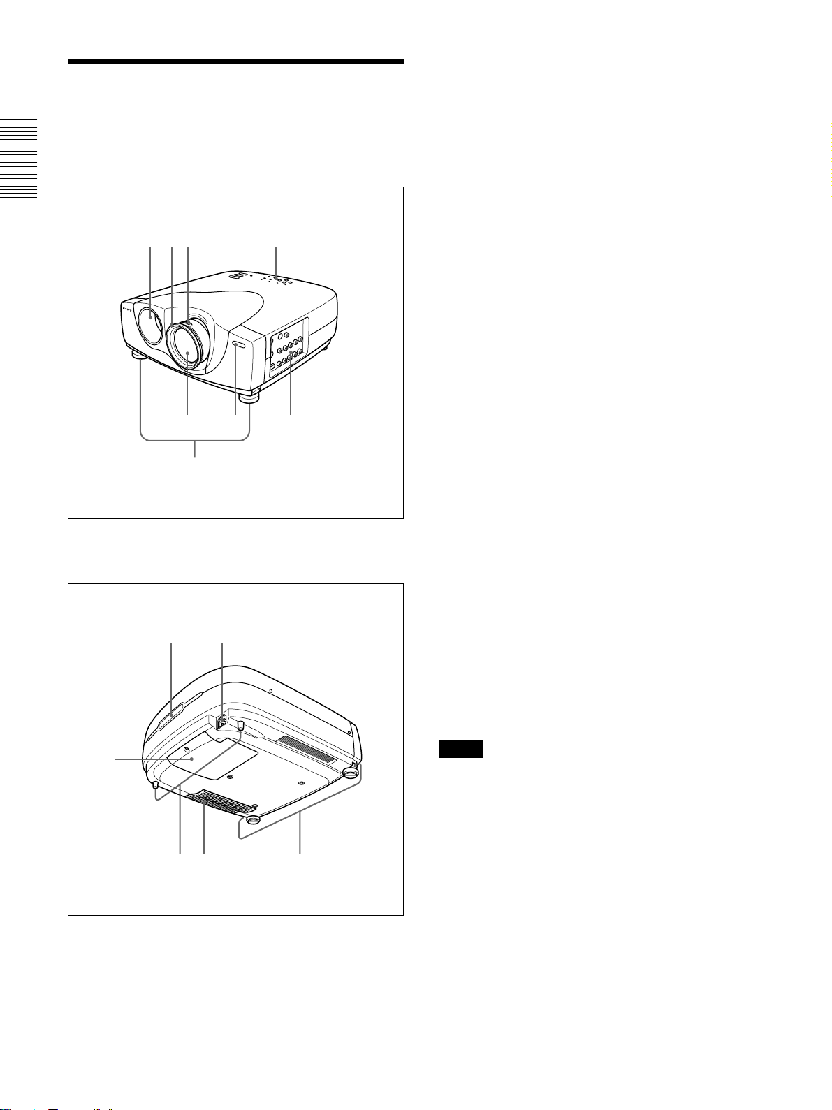
1 Zoom ring
Adjusts the size of the picture.
Controls
Front/Left Side
1823
4
6
57
2 Focus ring
Adjusts the picture focus.
3 Ventilation holes (exhaust)
4 Lens
Remove the lens cap before projection.
5 Front remote control detector (SIRCS receiver)
6 Adjusters
When a picture is projected on an exterior of the
screen, adjust the picture using these adjusters.
For details on how to use the adjusters, see “How to use
the adjusters” on page 11 (GB).
7 Connector panel
For details, see
8 Control panel
For details, see “Control Panel” on page 12 (GB).
9 AC IN socket
Connects the supplied AC power cord.
“Connector Panel” on
page 13 (GB).
Rear/Right Side/Bottom
0
qa
qs qd qf
9
0 Rear remote control detector (SIRCS receiver)
qa Lamp cover
qs Rear adjusters
qd Ventilation holes (intake)/air filter
About ventilation holes
Notes
•
Do not place anything near the ventilation holes as it
place
may cause internal heat build-up. Do not
hand near the ventilation holes, or you may be burned.
•To detect clogs accurately, reset the air filter the first
time you use the projector, and every time when you
replace the air filter.
•Replace and reset the air filter when a warning
message is displayed on the screen to ensure
optimal performance. This air filter cannot be
cleaned. You should also reset the air filter when
you use the projector for the first time.
your
10 (GB)
For details, see “Replacing the Air Filter!” on page 42
(GB).
qf Adjuster buttons
Location and Function of Controls
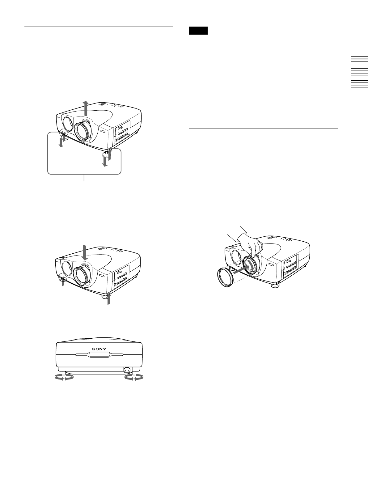
How to use the adjusters
To adjust the height
Adjust the height of the projector as follows:
1 Lift the projector and press the adjuster buttons.
The adjusters will extend from the projector.
Adjuster buttons
2 While pressing the buttons, adjust the height.
Then, release the buttons.
The adjusters will lock, then the height of the
projector will be fixed. For fine adjustment, turn
the adjusters to the right or left.
Notes
•Be careful not to let the projector down on your
fingers.
•Do not push hard on the top of the projector with the
adjusters out.
•If the adjusters are not extending from the projector
even though you have pressed the adjuster buttons,
loosen the adjusters by hand.
•If you move the projector with the adjusters
extended, the adjusters may be damaged. Move the
projector only after first retracting the adjusters.
How to use the supplied Cinema Filter
You can adjust the contrast by installing the supplied
Cinema Filter as follows.
1 Turn off the power and disconnect the power cord.
2 Align the screw of the filter with the thread around
the lens of the projector as illustrated below.
While holding the focus ring in place, turn the
filter clockwise.
3 If necessary, turn the rear adjusters to the right or
left to adjust the height of the projector.
Cinema Filter
11 (GB)
Location and Function of Controls
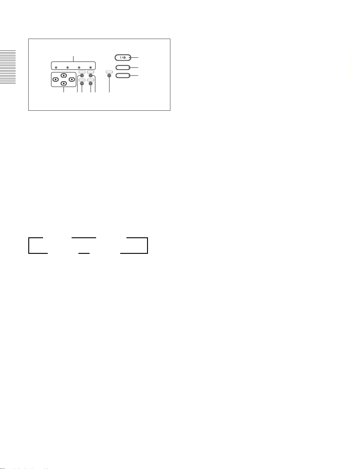
Control Panel
0
LAMP/
TEMP/
POWER
COVER
FAN
SAVING
MENU
ENTER
STANDBY
67
ON/
PATTERN
RESET
LIGHT
VIDEO MEMORY
4589
1 I / 1 (on / standby) key
Turns the projector on and off when the projector is in
the standby mode. (When the projector is in the
standby mode, the ON/STANDBY indicator lights in
red.) The ON/STANDBY indicator lights in green
when the power is turned on.
When turning off the power, press the I /
twice following the message on the screen, or press
and hold the key for about one second.
For details on steps for turning off the power, see “To turn
off the power” on page 22 (GB).
INPUT
1
2
3
1
key
6 RESET key
Resets the value of an item to its factory preset value.
This key functions when the menu or a setting item is
displayed on the screen.
7 ENTER key
Enters the settings of items in the menu system.
8 MENU key
Displays the on-screen menu. Press again to clear the
menu.
9 Arrow (M/m/</,) keys
Used to select a menu or to make various adjustments.
0 Indicators
LAMP/COVER: Lights up or flashes under the
following conditions:
• Lights up when the lamp has reached the end of
its life or the lamp does not turn on as a result
of high lamp temperature.
• Flashes when the lamp cover or air filter is not
secured firmly.
For further details, see troubleshooting on page 44 (GB).
2 INPUT key
Selects the input signal. Each time you press the key,
the input signal switches as follows:
B VIDEO B S-VIDEO
INPUT-B b INPUT-A b
3 VIDEO MEMORY key
You can adjust the image in advance and store the
setting in the VIDEO MEMORY 1 to 6. You can
recall the setting by pressing this key. Pressing this
key selects memory numbers 1 through 6. When you
keep on pressing, it selects OFF, and then starts again
with 1. You can easily set, change, and view the
image in a suitable setting.
For more details on how to set the video memory, see the
VIDEO MEMORY of the INPUT SETTING menu on page
27 (GB).
4 LIGHT key
If you press this key while the power is on, the keys
on the control panel will be displayed in orange.
Press this key again to turn off the light.
The light will turn off automatically if no keys are
operated for 30 seconds.
TEMP (Temperature)/FAN: Lights up or flashes
under the following conditions:
• Lights up when temperature inside the projector
becomes unusually high.
• Flashes when the fan is broken.
For further details, see troubleshooting on page 44 (GB).
POWER SAVING: Lights up when the projector is
in the power saving mode. When POWER
SAVING in the SET SETTING menu is set to
ON, the projector goes into the power saving
mode if no signal is input or no keys are operated
for 10 minutes. Although the lamp goes out, the
cooling fan keeps running. The power saving
mode is canceled when a signal is input or any
key is pressed. However, in the power saving
mode, none of the keys function for the first 40
seconds.
5 PATTERN key
Displays the test pattern on the screen for focus
adjustment. Press again to clear the test pattern.
12 (GB)
Location and Function of Controls
ON/STANDBY: Lights up or flashes under the
following conditions:
• Lights up in red when the AC power cord is
plugged into the wall outlet. Once in the
standby mode, you can turn on the projector
I / 1
with the
key.
• Lights up in green when the power is turned on.
• Flashes in green while the cooling fan runs after
I / 1
the power is turned off with the
key. The
fan runs for about 120 seconds after turning off
the power.
The ON/STANDBY indicator flashes quickly
for the first 40 seconds of that time.
During this first 40 seconds, you cannot turn the
I / 1
power back on with the
For details on the LAMP/COVER and the TEMP/FAN
indicators, see page 44 (GB).
key.
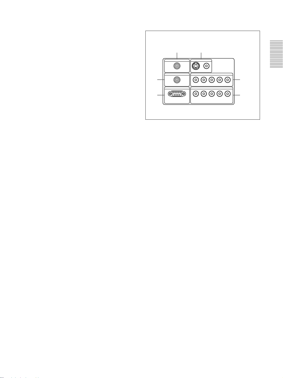
Connector Panel
Left side
56
CONTROL S IN VIDEO IN
PLUG IN POWER
TRIGGER
4
REMOTE
RS-232C
(FOR SERVICE USE)
1 INPUT A connectors
G/Y, B/C
B/PB, R/CR/PR, SYNC/HD, VD connectors
(phono type):
Connect to the RGB output of the equipment.
According to the connected equipment, computer,
component (Y/C
DTV YP
BPR) signal is selected.
S VIDEO
VIDEO
INPUT A
G/Y B/C
B/PB
R/CR/PRSYNC/HD VD
INPUT B
G/Y B/CB/PBR/CR/PRSYNC/HD VD
B/CR), HDTV or DTV (DTV GBR,
1
23
2 INPUT B connectors
G/Y, B/C
B/PB, R/CR/PR, SYNC/HD, VD connectors
(phono type):
Connect to the RGB output of the equipment.
According to the connected equipment, computer,
component (Y/C
DTV YP
BPR) signal is selected.
B/CR), HDTV or DTV (DTV GBR,
3 REMOTE (RS-232C) connector (D-sub 9-pin,
female)
This is a service connector. When the unit is
connected to a computer via this connector, you can
adjust the gamma values of the projector from the
computer using the ImageDirector software provided
on the CD-ROM that came with the projector.
For details, see the Operating Instructions provided on the
CD-ROM that came with the projector.
4 TRIGGER connector (minijack)
Outputs the ON or OFF condition of the unit to the
external equipment.
When the unit is turned off, 0 V is output and when
the unit is turned on, 12 V is output. However, as
power is not output, you cannot use the connector as a
power source.
13 (GB)
Location and Function of Controls
5 CONTROL S IN (PLUG IN POWER) (DC 5V
output) jack (stereo minijack)
Connects to the control S out jacks of Sony
equipment.
Connects to the CONTROL S OUT jack on the
supplied Remote Commander when using it as a wired
remote control. In this case, you do not need to install
batteries in the Remote Commander, since power is
supplied from this jack.
If this connector is used, the Remote Commander key
lamp is not turned on.
6 VIDEO IN connectors
Connect to external video equipment such as a VCR.
S VIDEO (mini DIN 4-pin):
Connects to the S video
output (Y/C video output) of video equipment.
VIDEO (phono type): Connects to the composite
video output of video equipment.
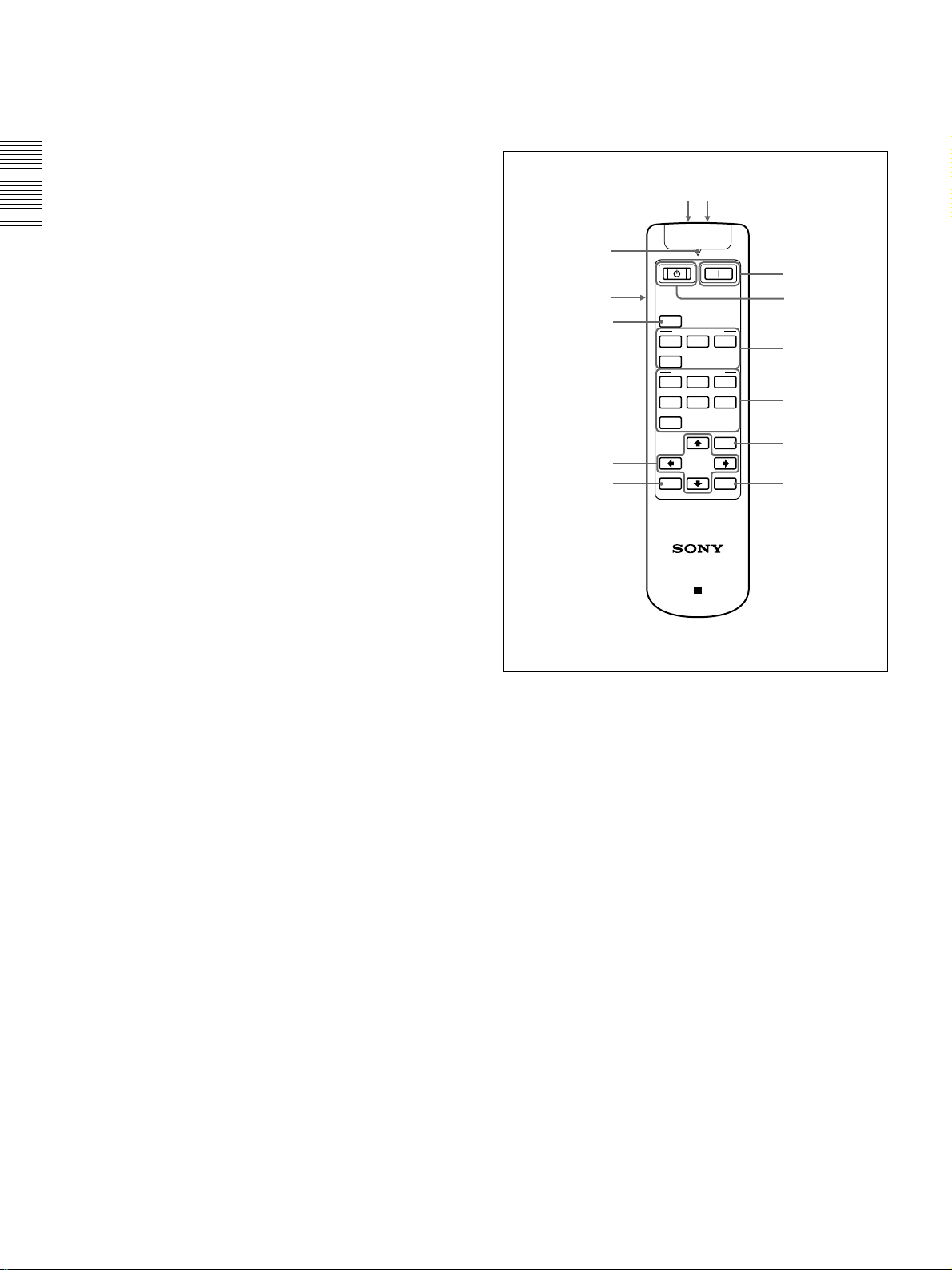
Remote Commander
Keys which have the same names as those on the
control panel function identically.
qsqd
qa
1
0
9
8
MUTING
PIC
INPUT SELECT
VIDEO
A
S VIDEO
VIDEO MEMORY
123
56
4
OFF
MENU
RESET
ENTER
B
2
3
4
5
67
PROJECTOR
RM-PJVW10
1
I
(ON) key
Press this key to turn on the projector. (It is assumed
that the projector is in the standby mode.)
1
(OFF) key
2
Press this key to turn off the power immediately.
3 INPUT SELECT keys
Select the input signal.
VIDEO: Selects the signal of equipment connected
to the projector’s VIDEO connector.
S VIDEO: Selects the signal of equipment
connected to the projector’s S VIDEO connector.
A: Selects the video signal of equipment connected
to the INPUT A connectors.
B: Selects the video signal of equipment connected
to the INPUT B connectors.
14 (GB)
Location and Function of Controls
4 VIDEO MEMORY keys
You can store an image setting to one of the VIDEO
MEMORY keys (1 – 6), and you can directly recall
the setting by pressing the appropriate key.
For more details on how to set the video memory, see the
VIDEO MEMORY of the INPUT SETTING menu on page
27 (GB).
5 MENU key
6 ENTER key
7 RESET key
8 Arrow (M/m/</,) keys
9 MUTING PIC key
Cuts off the picture. Press again to restore the picture.
0 LIGHT switch
Pressing this switch turns on the key light on the
Remote Commander. Pressing this switch again turns
off the key light. If no keys are operated, the lights
will automatically turn off in 30 seconds.
Install the two batteries in the Remote Commander
when you use the key light.
qa Transmission indicator
Lights up when you press a key on the Remote
Commander.
qs CONTROL S OUT jack (stereo minijack)
Connects to the CONTROL S IN jack on the projector
with the connecting cable (not supplied) when using
the Remote Commander as a wired remote control. In
this case, you do not need to install batteries since the
power is supplied via the CONTROL S IN jack on the
projector.
If batteries are not installed, the Remote Commander
key light is not turned on.
qd Infrared transmitter
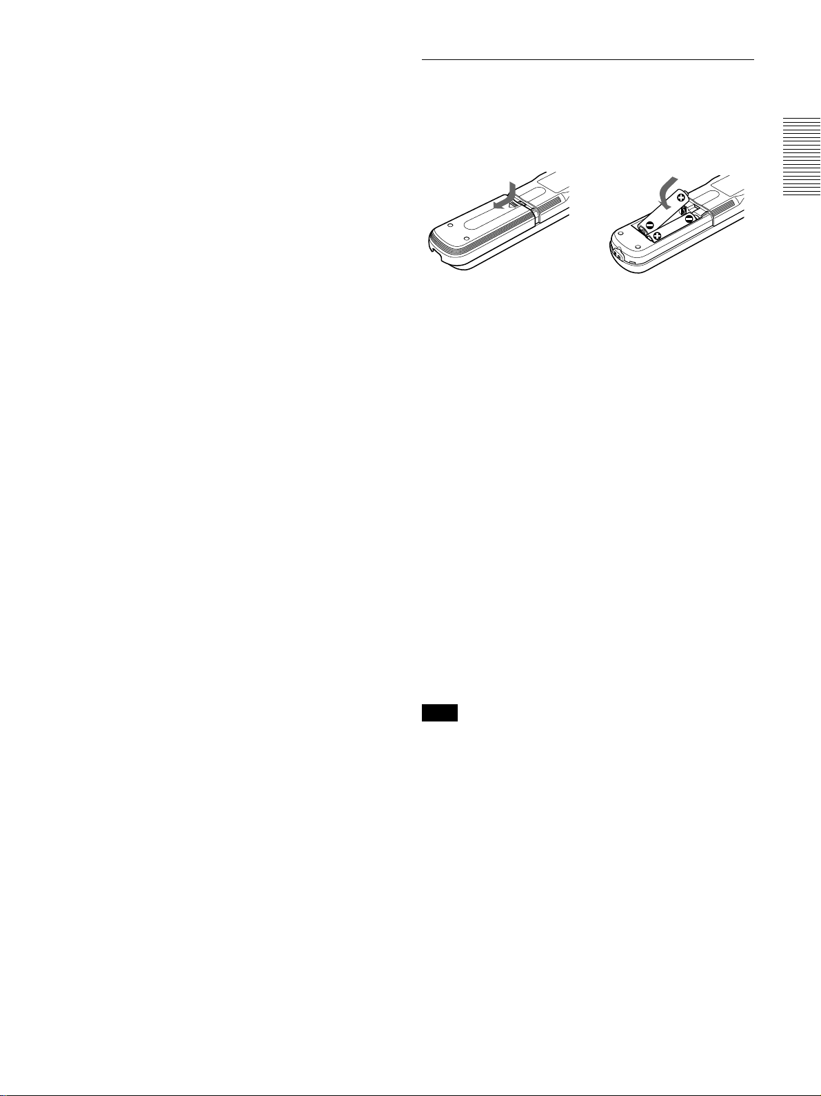
Battery installation
1 Push and slide to open the lid, then install the two
R6 (size AA) batteries (supplied) with the correct
polarity.
Slide while
pressing down
on the lid.
Be sure to
install the
battery from
the # side.
2 Replace the lid.
Notes on batteries
•Make sure that the battery orientation is correct when
inserting batteries.
•Do not mix an old battery with a new one, or
different types of batteries.
•If you do not intend to use the Remote Commander
for a long time, remove the batteries to avoid damage
from battery leakage. If batteries have leaked,
remove them, wipe the battery compartment dry and
replace the batteries with new ones.
Notes on Remote Commander operation
•Make sure that there is nothing to obstruct the
infrared beam between the Remote Commander and
the remote control detector on the projector.
•The operation range is limited. The shorter the
distance between the Remote Commander and the
projector is, the wider the angle within which the
commander can control the projector.
•To turn on the key light when using as a wired
Remote Commander, install the batteries.
Note
If the Remote Commander causes a malfunction,
consult with qualified Sony personnel. We will
exchange the Remote Commander for a new one
according to the guarantee.
15 (GB)
Installing the Projector / Connecting the Projector
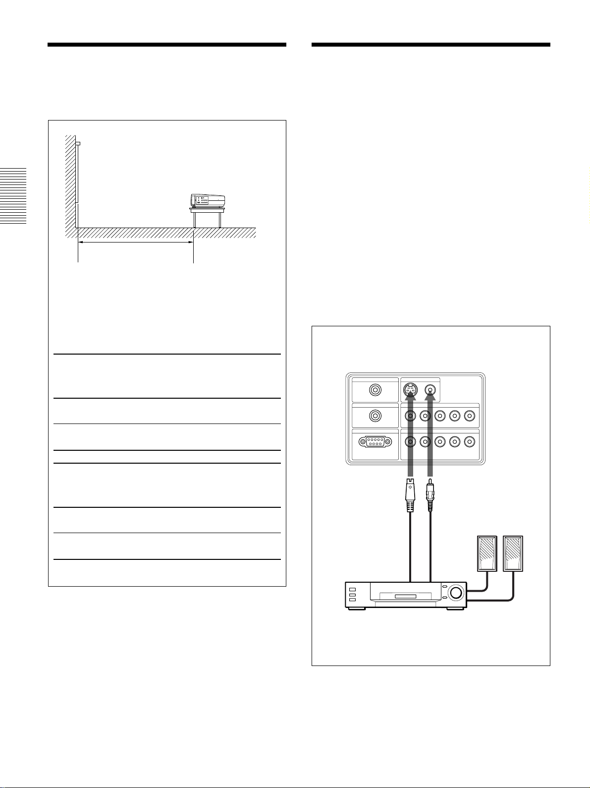
Installing the Projector
This section describes the installation arrangements
for installing the projector.
Distance between the screen
and the center of the lens
The distance between the lens and the screen varies
depending on the size of the screen.
Use the following table as a guide.
(For details, see “Installation Example” on page 32 (GB).)
Unit: m (feet)
16:9
screen
size
(inches)
Minimum 1.3 1.9 2.6 3.3 3.9 4.9 6.6 9.9
Distance (4.1) (6.3) (8.5) (10.7) (12.9) (16.2) (21.7) (32.6)
Maximum 1.5 2.2 3.0 3.8 4.6 5.7 7.6 11.5
Distance (4.8) (7.4) (9.8) (12.4) (14.9) (18.7) (25.0) (37.7)
40 60 80 100 120 150 200 300
Connecting the Projector
When making connections, be sure to do the
following:
Turn off all equipment before making any connections.
•
•Use the proper cables for each connection.
•Insert the cable plugs properly; plugs that are not
fully inserted often generate noise. When pulling out
a cable, be sure to pull it out grasping the plug, not
the cable itself.
Connecting to a VCR/15k RGB/
Component/Progressive
Component Equipment
This section describes how to connect the projector to
a VCR, external active speakers, and 15k RGB/
component/progressive component equipment.
For more information, refer to the instruction manuals
of the equipment you are connecting.
Left side
CONTROL S IN VIDEO IN
PLUG IN POWER
TRIGGER
REMOTE
RS-232C
(FOR SERVICE USE)
VIDEO
S VIDEO
INPUT A
B/PB
R/CR/PRSYNC/HD VD
G/Y B/C
INPUT B
G/Y B/CB/PBR/CR/PRSYNC/HD VD
4:3
screen
size
(inches)
Minimum 1.6 2.4 3.2 4.0 4.8 6.1 8.1 12.2
Distance (5.1) (7.8) (10.5) (13.2) (15.9) (19.9) (26.6) (40.0)
Maximum 1.8 2.8 3.7 4.7 5.6 7.0 9.4 14.1
Distance (6.0) (9.1) (12.3) (15.4) (18.3) (23.0) (30.8) (46.2)
40 60 80 100 120 150 200 300
S-Video cable
(not supplied)
to S video
output
Video cable
(not supplied)
Active speakers
to video
output
VCR
16 (GB)
 Loading...