

Sony VPL-SW125 Operating Instruction
Data
Projector
4-283-582-11 (2)
Operating Instructions
Before operating the unit, please read this manual and supplied Quick Reference Manual
thoroughly and retain it for future reference.
VPL-SX125
VPL-SW125
Not all models are available in all countries and area. Please check
with your local Sony Authorized Dealer.
© 2011 Sony Corporation

Table of Contents
Overview
Location and Function of Controls .... 3
Main unit ...................................... 3
Connector Panel ...........................4
Remote Commander and Control
Panel ..........................................5
Preparation
Connecting the Projector ................... 7
Connecting a Computer ................7
Connecting a Video equipment .... 8
Connecting an External Monitor and
Audio Equipment .................... 10
Projecting/Adjusting an
Image
Projecting an Image ......................... 11
Adjusting the Projected
image ....................................... 12
Turning Off the Power ................14
Adjustments and Settings
Using a Menu
Network
Using Network Features ...................27
Displaying the Control Window of
the Projector with a Web
Browser ...................................27
Confirming the Information
regarding the Projector ............28
Operating the Projector from a
Computer .................................28
Making the Network Settings .....28
Using the e-mail report
Function ...................................28
Others
Indicators ..........................................30
Messages List ...................................31
Troubleshooting ................................32
Replacing the Lamp ..........................34
Cleaning the Air Filter ......................36
Specifications ...................................37
Projection Distance ...........................42
Dimensions .......................................46
Index .................................................48
Using a MENU ................................15
The PICTURE SETTING Menu ...... 16
The INPUT SETTING Menu .......... 17
The SET SETTING Menu ............... 21
The MENU SETTING Menu .......... 23
The INSTALL SETTING Menu ...... 24
The INFORMATION Menu ............26
2
Table of Contents

B Overview
q
43
q
Location and Function of Controls
Main unit
1
0
6
qa
a
a Projection lens
b Focus ring (page 12)
c Lamp cover (page 34)
d Air filter cover (page 36)/
Ventilation holes (intake)
e Ventilation holes (intake)
f Ventilation holes (exhaust)
2
7
5
qa
g LAMP/COVER indicator
(page 30)
h Control panel (page 5)
i Connector panel (page 4)
j Remote control detector
k Adjuster (page 12)
l Speaker
m Security lock
Connects to an optional security cable
manufactured by Kensington.
For details, visit Kensington’s web site.
http://www.kensington.com/
n Security bar
Connects to a commercially available
security chain or wire.
If it is difficult to pull out, pull out the
Security bar using a screwdriver.
Overview
8
9
qs
qd
f
Caution
Do not place anything near the ventilation
holes as this may cause internal heat
buildup. Do not place your hand near the
ventilation holes and the circumference as
this may cause injury.
Security bar
Location and Function of Controls
3
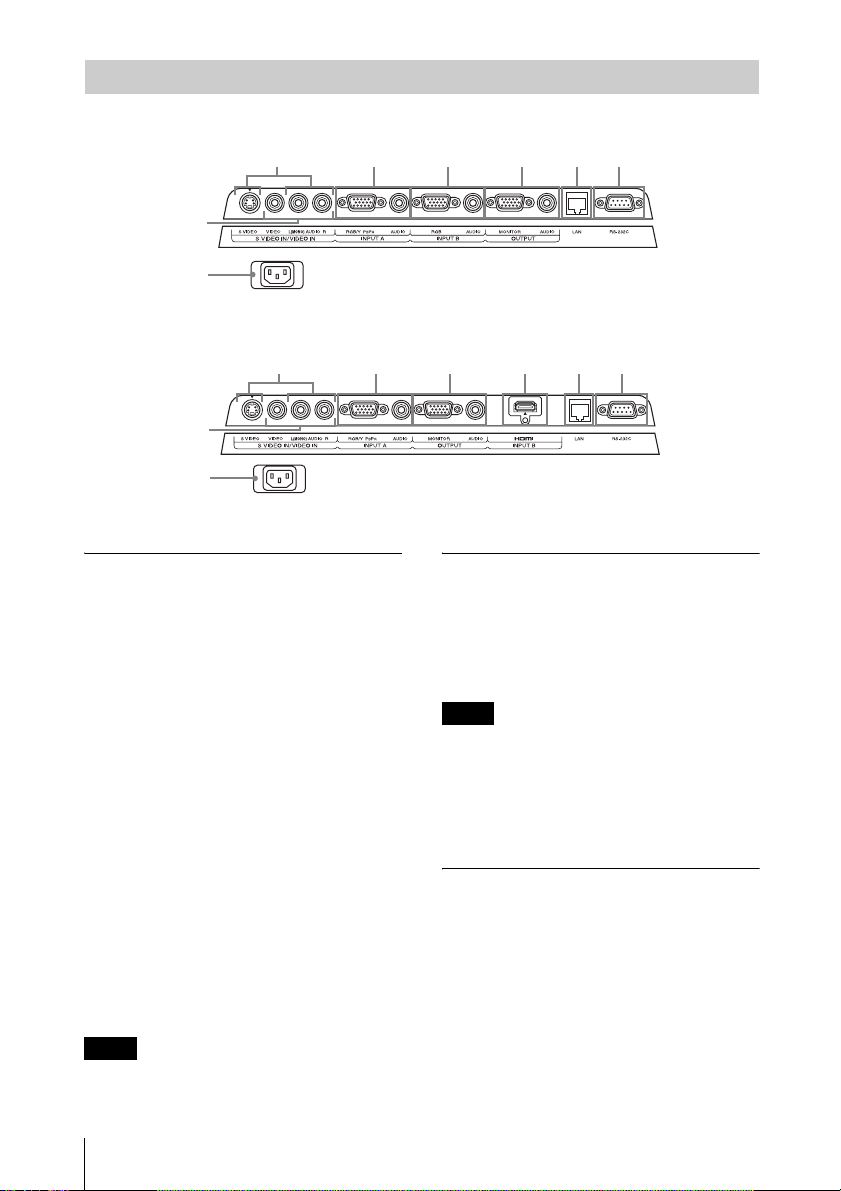
Connector Panel
VPL-SX125
4
1
5
9
VPL-SW125
4
1
5
9
Input (pages 7, 8)
a INPUT A
Video: RGB/YPBPR input connector
(RGB/YPBPR)
Audio: Audio input connector (AUDIO)
b INPUT B (VPL-SX125 only)
Video: RGB input connector (RGB)
Audio: Audio input connector (AUDIO)
c INPUT B (VPL-SW125 only)
Video: HDMI input connector (HDMI)
Audio: HDMI input connector (HDMI)
d S VIDEO (S VIDEO IN)
Video: S video input connector
Audio: Audio input connector (L
[MONO] AUDIO/R)
e VIDEO (VIDEO IN)
Video: Video input connector
Audio: Audio input connector (L
[MONO] AUDIO/R)
Note
The audio inputs of S VIDEO and VIDEO are
shared.
2 6 8
6 3 8
7
7
Output (page 10)
f OUTPUT
Video: Monitor output connector
(MONITOR)
Audio: Audio output connector
(AUDIO)
Note
This connector outputs the projected image or
audio. The image is output as a computer signal
input from the RGB input connector (INPUT
A/INPUT B (INPUT B is available only for
VPL-SX125)) or a video signal input from the
YPBPR input connector (INPUT A).
Others
g RS-232C connector
RS-232C compatible control connector.
Connects the computer’s RS-232C
connector and the RS-232C cross cables.
h LAN connector (page 27)
i AC IN (∼) socket
Connects the supplied AC power cord.
4
Location and Function of Controls
Remote Commander and Control Panel
7
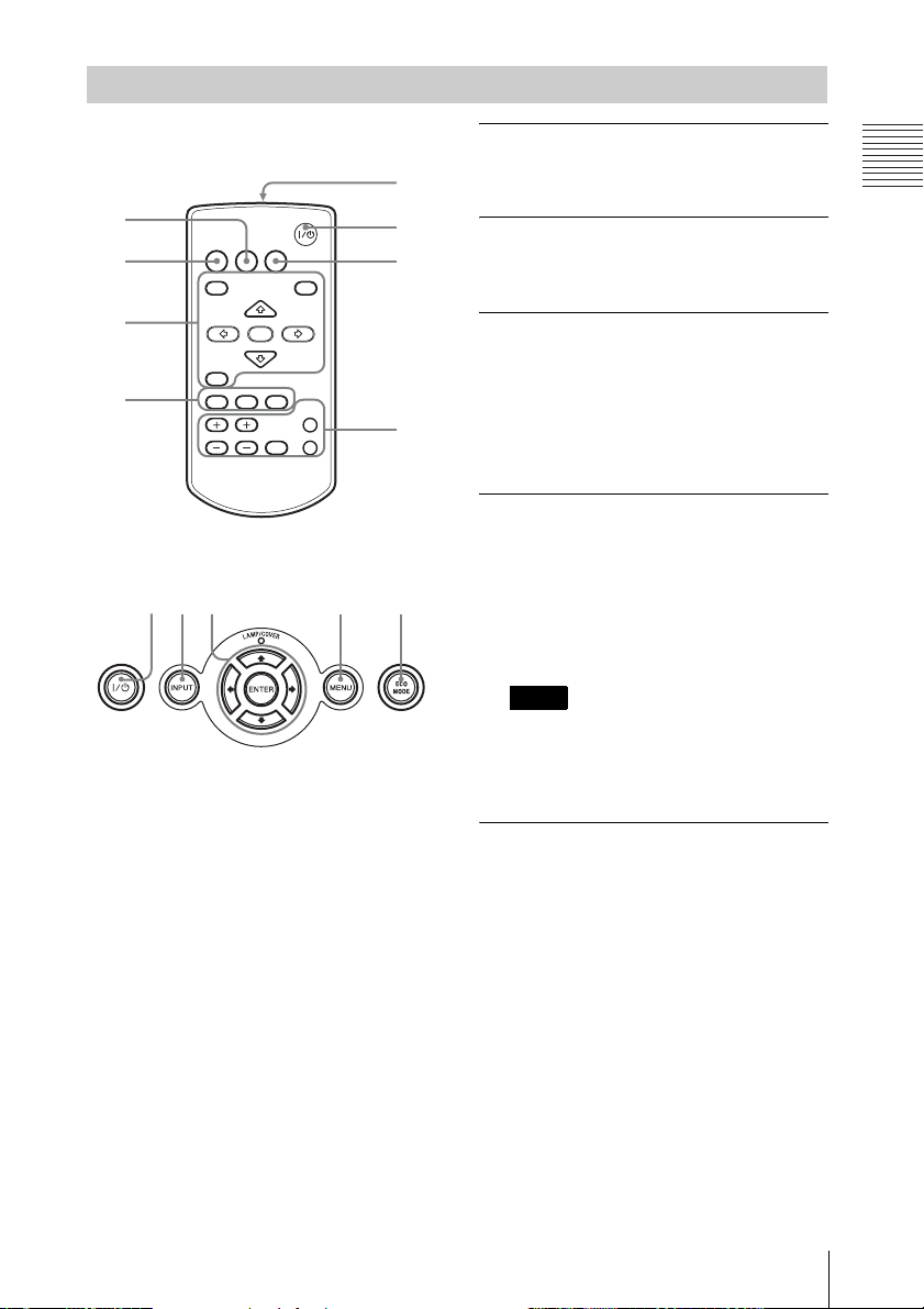
Remote Commander
4
INPUT
APA ECO MODE
2
3
4
Control Panel
123 3 6
MENU
RETURN
ASPECT
D ZOOM
KEYSTONE
VOLUME
ENTER
PATTERN
FREEZE
RESET
PIC MUTING
AUDIO MUTING
1
6
5
a Turning on the power/Going to
standby mode
?/1 (On/Standby) key
b Selecting an input signal
(page 11)
INPUT key
c Operating a menu (page 15)
MENU key
RESET key
ENTER /V/v/B/b (arrow) keys
RETURN key
This function is not provided in this
projector.
d Adjusting the image (page 12)
ASPECT key
KEYSTONE key
PATTERN key
This function is not provided in this
projector.
APA (Auto Pixel Alignment) key
Note
* Use this key when inputting a computer
signal via the RGB input connector
(INPUT A/INPUT B (INPUT B is
available only for VPL-SX125)).
Overview
*
e Using various functions during
projecting
D ZOOM (Digital Zoom) +/– key
*1
Enlarges a portion of the image while
projecting.
1 Press the D ZOOM + key to display
the digital zoom icon on the projected
image.
2 Press the V/v/B/b keys to move the
digital zoom icon to the point on the
image you wish to enlarge.
3 Press the D ZOOM + key or the D
ZOOM – key repeatedly to change the
enlargement ratio. The image can be
enlarged up to 4 times.
Press the RESET key to restore the
previous image.
Location and Function of Controls
5
PIC MUTING key
Cuts off the image. Press again to restore
the image.
AUDIO MUTING key
Mutes the audio output. Press again to
restore the previous volume.
VOLUME +/– key
For adjusting the volume output.
FREEZE key
*2
Pauses a projected image. Press again to
restore the image.
Notes
*1: Use this key when inputting a
computer signal. But it may not be
used depending on the resolution of
the input signal.
*2: Use this key when inputting a
computer signal.
f Setting the energy–saving mode
easily
ECO MODE key
Energy-saving mode can be set easily.
Energy-saving mode consists of “Lamp
Mode,” “Power Saving Mode” and
“Standby Mode.”
1 Press the ECO MODE key to display
the ECO Mode menu.
ECO Mode Menu
ECO Mode
ECO
User
Sel: Exit:
2 Press the V/v key or ECO MODE key
to select ECO or User mode.
ECO: Sets each mode to the optimum
energy-saving value.
Lamp Mode: Low
Power Saving Mode: Standby
Standby Mode: Low
(go to step 6)
User: Sets each item of the energy-
saving mode menu as you desire
(go to step 3).
3 Select “User” then press the b key.
The setting items appear.
User
Lamp Mode Standard
Power Saving Mode Off
Standby Mode Low
Sel: Set: Exit:
4 Press the V/v key to select the item
then press the ENTER key.
5 Press the V/v key to select the setting
value.
6 Press the ENTER key to restore the
User screen.
For details on ECO Mode settings, see
“Lamp Mode” (page 24) and “Standby
*4
” (page 24) on the INSTALL
Mode
SETTING menu and “Power Saving
Mode” (page 21) on the SET SETTING
menu.
Others
g Infrared transmitter
About Remote Commander operation
• Direct the Remote Commander toward the
remote control detector.
• The shorter the distance between the
Remote Commander and the projector is,
the wider the angle within which the
Remote Commander can control the
projector becomes.
• Make sure that nothing obstructs the
infrared beam between the Remote
Commander and the remote control
detector on the projector.
6
Location and Function of Controls
B Preparation
Connecting the Projector
Notes
• Make sure all the equipment is powered off when connecting the projector.
• Use the proper cables for each connection.
• Insert the cable plugs firmly; Loose connections may reduce performance of picture signals or
cause a malfunction. When pulling out a cable, be sure to grip it by the plug, not the cable itself.
• For more information, refer also to the instruction manuals of the equipment you are connecting.
• Use a no-resistance audio cable.
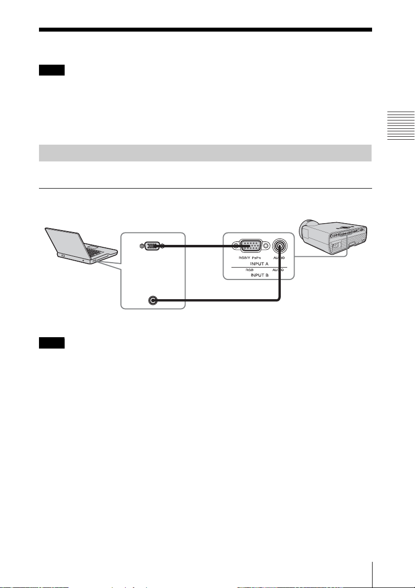
Connecting a Computer
Connection with a computer is explained for each input signal.
INPUT A/INPUT B (INPUT B is available only for VPL-SX125)
For connecting a computer with an RGB output connector.
Mini D-sub 15-pin cable (supplied)
RGB output
Computer
connector
Audio output
connector
Preparation
Audio cable (Stereo mini plug) (not supplied)
Note
It is recommended that you set the resolution of your computer to 1024 × 768 pixels (VPL-SX125)
or 1280 × 800 pixels (VPL-SW125) for the external monitor.
Connecting the Projector
7
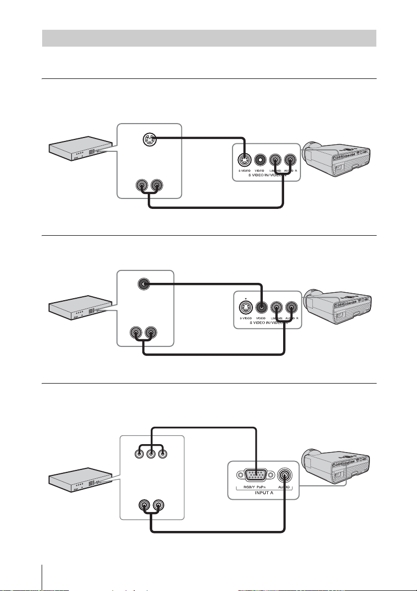
Connecting a Video equipment
Connections with a VHS video deck, DVD player, or BD player are explained for each input
signal.
S VIDEO IN
For connecting video equipment with an S-video output connector.
S video cable
(not supplied)
S video output
connector
Video equipment
VIDEO IN
For connecting video equipment with a video output connector.
Video equipment
Audio output
connector
Audio cable (Phono plug × 2) (not supplied)
Video cable (not supplied)
Video output
connector
Audio output
connector
Audio cable (Phono plug × 2) (not supplied)
INPUT A
For connecting video equipment with a YPBPR output connector.
Component – Mini D-sub 15-pin cable (not supplied)
YPBPR output
connector
Audio output
Video equipment
8
Connecting the Projector
connector
Audio cable (Phono plug × 2 – stereo mini plug) (not supplied)
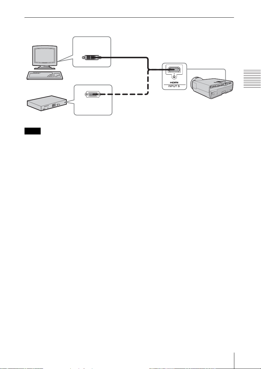
INPUT B (VPL-SW125 only)
For connecting video equipment with an HDMI output connector.
Computer
Video equipment
Notes
DVI-D output
connector
HDMI output
connector
HDMI-DVI-D cable
(not supplied)
HDMI cable
(not supplied)
• Use HDMI-compatible equipment and cable(s) that have an HDMI logo on them.
• The HDMI connector of this projector is not compatible with DSD (Direct Stream Digital) Signal
or CEC (Consumer Electronics Control) Signal.
Preparation
Connecting the Projector
9
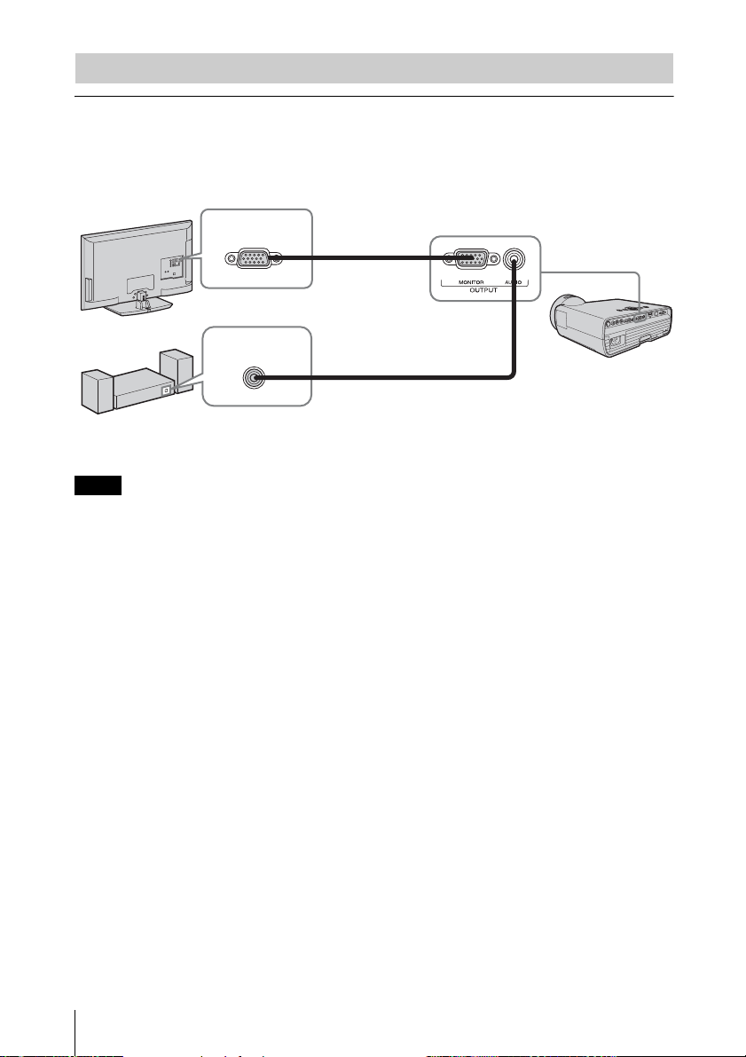
Connecting an External Monitor and Audio Equipment
OUTPUT
Projected images and input audio can be output to display equipment such as a monitor and
audio equipment such as speakers with a built-in amplifier. When an audio cable is connected
to the audio output connector, no sound will be heard from the built-in speaker.
Display equipment
Audio equipment
Note
RGB input
connector
Audio input
connector
Mini D-sub 15-pin
cable (supplied)
Audio cable
(stereo mini plug)
(not supplied)
Projected images and audio can be output. The image is output only as a computer signal input from
the RGB input connector (INPUT A/INPUT B (INPUT B is available only for VPL-SX125)) or a
video signal input from the YPBPR input connector (INPUT A).
10
Connecting the Projector
B Projecting/Adjusting an Image
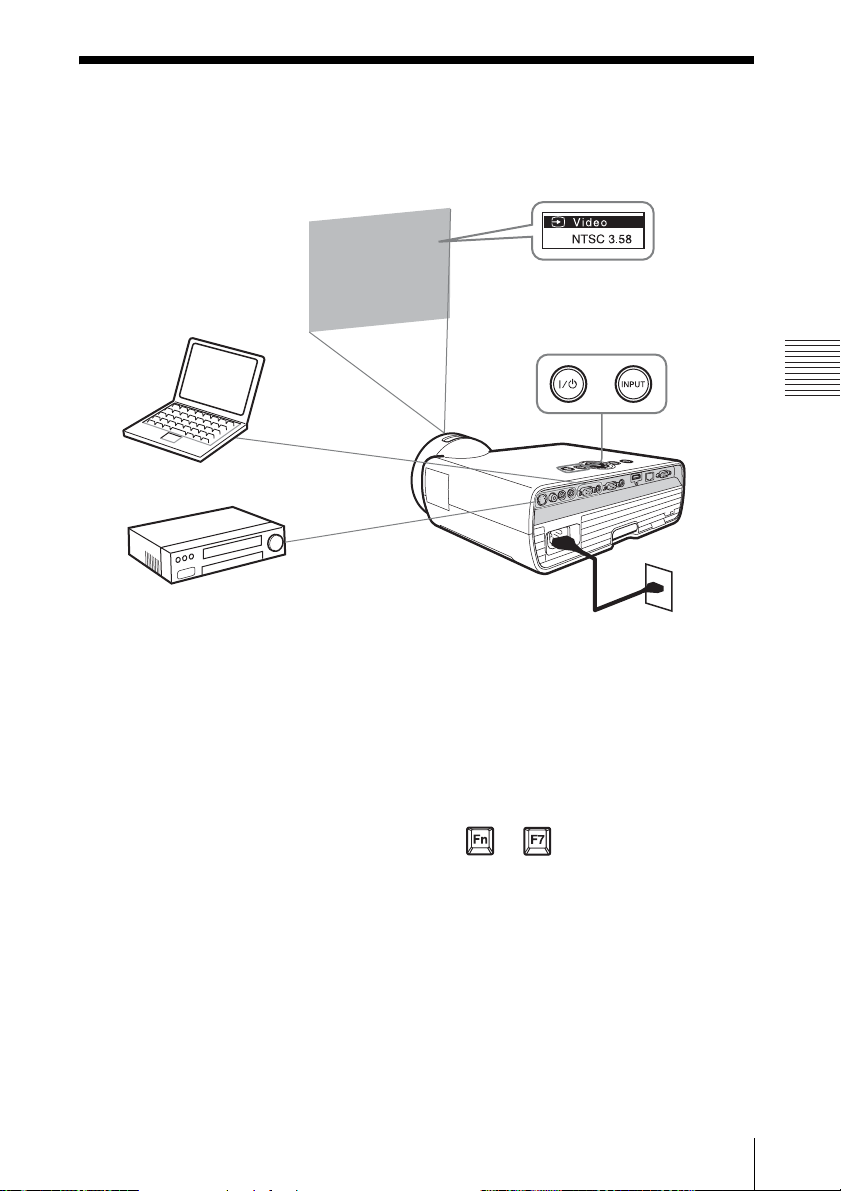
Projecting an Image
The size of a projected image depends on the distance between the projector and screen. Install
the projector so that the projected image fits the screen size. For details on projection distances
and projected image sizes, see “Projection Distance” (page 42).
5
35
4
Computer
6
Video equipment
1 Plug the AC power cord into the wall
outlet.
2 Connect all equipment to the projector
(page 7).
3 Press ?/1 to turn on the unit.
4 Turn on the connected equipment.
5 Select the input source.
Each time you press the INPUT key on
the projector, the input signal switches.
Press the INPUT key repeatedly to select
an image to be projected.
2
Projector
1
Wall outlet
6 Switch your computer to output to
external display by changing your
computer’s setting.
How to switch the computer to output to
the projector varies, depending on the
type of computer.
(Example)
+
7 Adjust the focus and position of the
projected image (page 12).
Projecting/Adjusting an Image
Projecting an Image
11
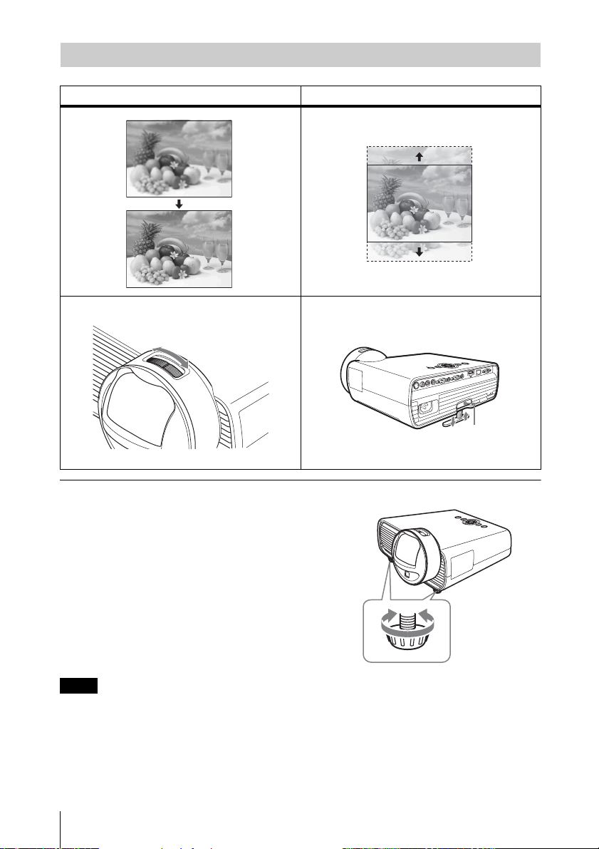
Adjusting the Projected image
Focus Position
Adjuster adjustment button
Adjusting the tilt of the projector with the adjusters
You can adjust the height of the projector
using the adjusters.
By changing the slope of the projector with
adjusters, you can adjust the position of the
projected image.
Notes
• Be careful not to let the projector down on your fingers.
• Do not push hard on the top of the projector with the adjuster extended. It may cause malfunction.
12
Projecting an Image
Changing the aspect ratio of the projected image
Press ASPECT on the remote commander to change the aspect ratio of the projected image.
You can also change the setting in Aspect of the INPUT SETTING menu (page 17, page 19).
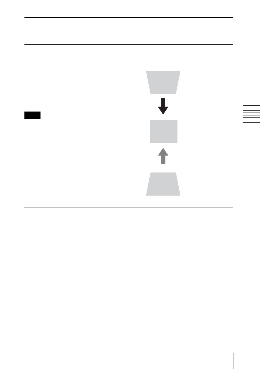
Correcting trapezoidal distortion of the projected image (Keystone feature)
Keystone feature may not work automatically when the screen is tilted. In this case, set
keystone manually.
1 Press KEYSTONE on the remote
commander or select V Keystone in the
INSTALL SETTING menu.
2 Use V/v/B/b to set the value. The higher
the setting, narrower the top of the
projected image. The lower the setting, the
narrower the bottom.
Note
Since the Keystone adjustment is an electronic
correction, the image may be deteriorated.
Increase the number
towards plus
Increase the number
towards minus
Projecting/Adjusting an Image
Automatically adjusts Phase, Pitch and Shift of projected image while a
signal is input from a computer (APA (Auto Pixel Alignment))
Press APA on the remote commander. Press again to cancel during the setting.
If Smart APA is set to On, executes APA automatically when a signal is input (page 21).
Projecting an Image
13

Turning Off the Power
1 Press the ?/1 key on the main unit or the Remote Commander.
The message appears. Press it again according to the message.
2 Unplug the AC power cord from the wall outlet.
After step 1, the fan continues to run for a while to reduce internal heat, however, you may
also unplug the AC power cord before the fan stops.
To clear the confirmation message
The message disappears if you press any key other than the ?/1 key on the main unit or the
Remote Commander, or if you do not press any key for a while.
To turn off without displaying confirmation message
Hold the ?/1 key on the main unit pressed for a few seconds.
14
Projecting an Image
B Adjustments and Settings Using a Menu
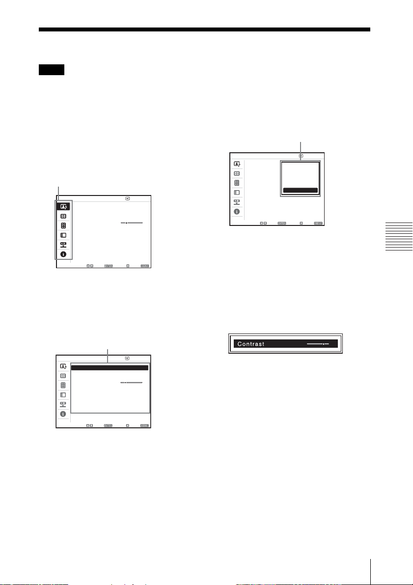
Using a MENU
Note
The menu displays used for the explanation below may be different depending on the model you are
using.
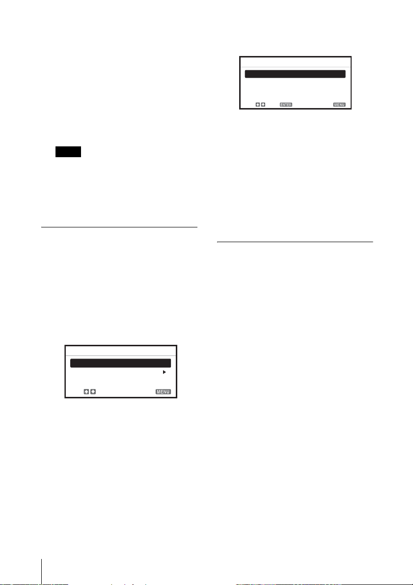
1 Press the MENU key to display the
menu.
2 Select the setting menu.
Use the V or v key to select the setting
menu then press b or ENTER key.
Setting menu
PICTURE SETTING Input-A
Picture Mode Presentation
Adjust Picture...
Volume 30
Sel: Set: Back: Eixt:
3 Select the setting item.
Use the V or v key to select the setting
menu then press b or ENTER key.
To return to the selection screen of the
setting menu, press the B key.
Setting items
PICTURE SETTING Input-A
Picture Mode Presentation
Adjust Picture...
Volume 30
factory preset value, press the RESET
key during setting or adjusting.
Selecting items
PICTURE SETTING Input-A
Picture Mode Standard
Adjust Picture...
Volume 30
Sel: Set: Back: Eixt:
Dynamic
Standard
Game
Living
Cinema
Presentation
Using the setting menu
Press the V or v key to select the item.
Press the ENTER key to restore the
previous screen.
Using the adjustment menu
To increase the number, press the V or b
key and to decrease the number, press
the v or B key. Press the ENTER key to
register the setting. The previous screen
is restored.
90
5 Press the MENU key to clear the
menu.
The menu disappears automatically if no
key is pressed for a while.
Adjustments and Settings Using a Menu
Sel: Set: Back: Eixt:
4 Make the setting or adjustment for the
selected item.
Menu operation differs depending on the
setting item. If the next menu window is
displayed, select the item according to
the operations in step 3.
To return to the selection screen of the
setting items, press the B key. Also, to
reset the setting value of an item to its
Using a MENU
15
 Loading...