

Page 1

S
ony Corporation
Printed in Japan
© 2013 Sony Corporation
4-484-003-21 (2)
Video Projector
VPL-HW55ES
Operating Instructions
Mode d’emploi
Manual de instrucciones
Bedienungsanleitung
Istruzioni per l’uso
FR
ES
DE
IT
GB
Video Projector VPL-HW55ES
Page 2

Before operating the unit, please read this
manual thoroughly and retain it for future
reference.
WARNING
To reduce the risk of fire or
electric shock, do not expose
this apparatus to rain or
moisture.
To avoid electrical shock, do
not open the cabinet. Refer
servicing to qualified
personnel only.
THIS APPARATUS MUST BE
EARTHED.
For the customers in the U.S.A.
This equipment has been tested and found to
comply with the limits for a Class B digital
device, pursuant to part 15 of the FCC Rules.
These limits are designed to provide
reasonable protection against harmful
interference in a residential installation. This
equipment generates, uses and can radiate
radio frequency energy and, if not installed
and used in accordance with the instructions,
may cause harmful interference to radio
communications. However, there is no
guarantee that interference will not occur in
a particular installation. If this equipment
does cause harmful interference to radio or
television reception, which can be
determined by turning the equipment off and
on, the user is encouraged to try to correct
the interference by one or more of the
following measures:
- Reorient or relocate the receiving antenna.
- Increase the separation between the
equipment and receiver.
- Connect the equipment into an outlet on a
circuit different from that to which the
receiver is connected.
- Consult the dealer or an experienced
radio/TV technician for help.
You are cautioned that any changes or
modifications not expressly approved in this
manual could void your authority to operate
this equipment.
All interface cables used to connect
peripherals must be shielded in order to
comply with the limits for a digital device
pursuant to Subpart B of part 15 of FCC
Rules.
If you have any questions about this product,
you may call;
Sony Customer Information Service Center
1-800-222-7669 or http://www.sony.com/
Declaration of Conformity
Trade Name: SONY
Model: VPL-HW55ES
Responsible party: Sony Electronics Inc.
Address: 16530 Via Esprillo,
San Diego, CA 92127
U.S.A.
Telephone Number:858-942-2230
This device complies with part 15 of the
FCC Rules. Operation is subject to the
following two conditions: (1) This device
may not cause harmful interference, and
(2) this device must accept any interference
received, including interference that may
cause undesired operation.
For the customers in Canada
CAN ICES-3 (B)/NMB-3(B)
For the customers in Europe
This product has been manufactured by or
on behalf of Sony Corporation, 1-7-1 Konan
Minato-ku Tokyo, 108-0075 Japan.
Inquiries related to product compliance
based on European Union legislation shall
be addressed to the authorized
representative, Sony Deutschland GmbH,
Hedelfinger Strasse 61, 70327 Stuttgart,
Germany. For any service or guarantee
matters, please refer to the addresses
provided in the separate service or guarantee
documents.
For kundene i Norge
Dette utstyret kan kobles til et ITstrømfordelingssystem.
GB
2
Page 3

For the customers in Taiwan only
For the Customers in Brazil only
DESCARTE DE PILHAS E BATERIAS
Pilhas e Baterias não recarregáveis
Atenção:
Verifique as instruções de uso do aparelho
certificando-se de que as polaridades (+) e
(-) estão no sentido indicado. As pilhas
poderão vazar ou explodir se as polaridades
forem invertidas, expostas ao fogo,
desmontadas ou recarregadas.
Evite misturar com pilhas de outro tipo ou com
pilhas usadas, transportá-las ou armazená-las
soltas, pois aumenta o risco de vazamento.
Retire as pilhas caso o aparelho não esteja
sendo utilizado, para evitar possíveis danos
na eventualidade de ocorrer vazamento.
As pilhas devem ser armazenadas em local
seco e ventilado.
No caso de vazamento da pilha, evite o
contato com a mesma. Lave qualquer parte
do corpo afetado com água abundante.
Ocorrendo irritação, procure auxílio médico.
Não remova o invólucro da pilha.
Mantenha fora do alcance das crianças. Em
caso de ingestão procure auxílio médico
imediatamente.
DESCARTE DE PILHAS E BATERIAS
Este produto contém bateria de alimentação
integrada (não removível pelo usuário) que
só deve ser substituída por profissionais
qualificados. Ao fim da vida útil do
equipamento, disponha-o em um ponto de
coleta na Rede Autorizada Sony ou nas lojas
Sony, de forma a garantir o tratamento
adequado da bateria.
For the customers in the U.S.A.
SONY LIMITED WARRANTY - Please
visit http://www.sony.com/psa/warranty
for important information and complete
terms and conditions of Sony’s limited
warranty applicable to this product.
For the customers in Canada
SONY LIMITED WARRANTY
- Please
visit http://www.sonybiz.ca/solutions/
Support.do for important information and
complete terms and conditions of Sony’s
limited warranty applicable to this product.
For the customers in Europe
Sony Professional Solutions Europe Standard Warranty and Exceptions on
Standard Warranty.
Please visit http://www.pro.sony.eu/
warranty for important information and
complete terms and conditions.
For the customers in Korea
SONY LIMITED WARRANTY
- Please
visit http://bpeng.sony.co.kr/handler/
BPAS-Start for important information and
complete terms and conditions of Sony’s
limited warranty applicable to this product.
GB
GB
3
Page 4

Table of Contents
Precautions .........................................6
Location of Controls
Front/Right Side .................................8
Rear/Bottom .......................................9
Remote Control ................................10
Connections and
Preparations
Unpacking ........................................11
Step 1: Installing the Projector .........13
Before Setting Up the
Projector .....................................13
Safety precautions for installing the
unit on a ceiling ..........................14
Installing the Unit .......................15
Step 2: Adjusting the Picture
Position ............................................16
Step 3: Connecting the Projector .....21
Connecting to a VCR ................. 21
Connecting to a Computer ......... 23
Connecting to a 3D Sync
Transmitter ................................. 24
Step 4: Selecting the Menu
Language ..........................................25
Function ......................................33
Using the 3D Glasses ..................33
Selecting the Picture Viewing
Mode ................................................36
Using “ImageDirector3” to Adjust
the Picture Quality ............................37
Adjusting the Picture Quality ...........38
Selecting to Directly Adjust the
Desired Menu Item .....................38
Adjusting the Picture Using Real Color
Processing .........................................39
Using the Menus
Operation through the Menus ...........41
Picture Menu ....................................45
Advanced Picture Menu ...................50
Screen Menu .....................................51
Setup Menu .......................................53
Function Menu .................................55
Items Locked by Settings
Lock ..........................................58
Installation Menu ..............................59
Information Menu .............................61
About the Preset Memory No. ....62
Others
Projecting
Projecting the Picture .......................27
Turning Off the Power ............... 28
Selecting the Aspect Ratio According to
the Video Signal ...............................29
Watching 3D Video Images .............32
Using the Simulated 3D
GB
4
About the Control for HDMI ............63
About the x.v.Color ..........................64
About the simulated 3D feature ........64
Troubleshooting ................................65
Warning Indicators .....................68
Message Lists ..............................69
Page 5

Replacing the Lamp and the Air Filter
and Cleaning the Ventilation Holes
(intake) .............................................71
Cleaning the Air Filter .....................74
Fitting the Lens Cap .........................74
Cleaning ...........................................75
Specifications ...................................75
Preset Signals .............................77
Input Signals and Adjustable/
Setting Items ...............................79
Compatible 3D Signals ...............81
3D Signals and Adjustable/
Setting Items ...............................81
Aspect Mode ...............................83
Storage Conditions of Adjustable/
Setting Items ...............................84
Projection Distance and Lens Shift
Range ...............................................86
Index ...............................................90
Trademark Information
“PS3” is a registered trademark of Sony
Computer Entertainment Inc.
The terms HDMI and HDMI HighDefinition Multimedia Interface, and the
HDMI Logo are trademarks or registered
trademarks of HDMI Licensing LLC in the
United States and other countries.
“Blu-ray” and “Blu-ray Disc” are trademarks
of Blu-ray Disc Association.
..........................................................................
Control for HDMI is an HDMI standard mutual
control function which uses the HDMI CEC
(Consumer Electronics Control) specification.
This projector supports DeepColor, x.v.Color,
LipSync, 3D signal and computer input signal
of HDMI standards. It also supports HDCP.
5
GB
Page 6

Precautions
On safety
• Check that the operating voltage of your
unit is identical with the voltage of your
local power supply.
• Should any liquid or solid object fall into
the cabinet, unplug the unit and have it
checked by qualified personnel before
operating it further.
• Unplug the unit from the wall outlet if it is
not to be used for several days.
• To disconnect the cord, pull it out by the
plug. Never pull the cord itself.
• The wall outlet should be near the unit and
easily accessible.
• The unit is not disconnected to the AC
power source (mains) as long as it is
connected to the wall outlet, even if the
unit itself has been turned off.
• Do not look into the lens while the lamp is
on.
• Do not place your hand or objects near the
ventilation holes. The air coming out is
hot.
On preventing internal heat buildup
After you turn off the power with the I/1
(ON/STANDBY) switch, do not disconnect
the unit from the wall outlet while the
cooling fan is still running.
Caution
The projector is equipped with ventilation
holes (intake) and ventilation holes
(exhaust). Do not block or place anything
near these holes, or internal heat build-up
may occur, causing picture degradation or
damage to the projector.
On repacking
Save the original shipping carton and
packing material; they will come in handy if
you ever have to ship your unit. For
maximum protection, repack your unit as it
was originally packed at the factory.
Safety precautions when using 3D
Glasses
Warning
• Do not put the 3D Glasses in a fire.
• Do not disassemble the 3D Glasses.
• Do not use, charge, store, or leave the 3D
Glasses near a fire, or in places with a high
temperature, e.g., in direct sunlight, or in
sun-heated cars.
• Use only the supplied USB cable.
• Do not allow water or foreign material to
enter the 3D Glasses.
Safety precautions
• Use only the type of 3D glasses included
with this unit. You should only use the 3D
glasses for watching 3D video images. Do
not use the 3D Glasses with other
equipment, such as TV.
• If you observe flickering or flashing, turn
off the lighting in the room.
• Not for use by children without proper
adult supervision.
• Be careful not to pinch your fingers in
hinges of the 3D glasses when bending the
temple frames.
• Do not drop or modify these 3D glasses.
• If these glasses are broken, keep broken
pieces away from your mouth or eyes.
On LCD Projector
The LCD projector is manufactured using
high-precision technology. You may,
however, see tiny black points and/or bright
points (red, blue, or green) that continuously
appear on the LCD projector. This is a
normal result of the manufacturing process
and does not indicate a malfunction.
Also, when you use multiple LCD projectors
to project onto a screen, even if they are of
the same model, the color reproduction
among projectors may vary, since color
balance may be set differently from one
projector to the next.
GB
6
Page 7

On condensation
If the room temperature where the projector
is installed changes rapidly, or if the
projector is moved suddenly from a cold to a
warm place, condensation in the projector
may occur. As the condensation may cause
malfunction, be careful in adjusting
temperature settings of the air conditioner. If
condensation occurs, leave the projector
turned on for about two hours before use.
SONY WILL NOT BE LIABLE FOR
DAMAGES OF ANY KIND
RESULTING FROM A FAILURE TO
IMPLEMENT PROPER SECURITY
MEASURES ON TRANSMISSION
DEVICES, UNAVOIDABLE DATA
LEAKS RESULTING FROM
TRANSMISSION SPECIFICATIONS,
OR SECURITY PROBLEMS OF ANY
KIND.
GB
7
Page 8
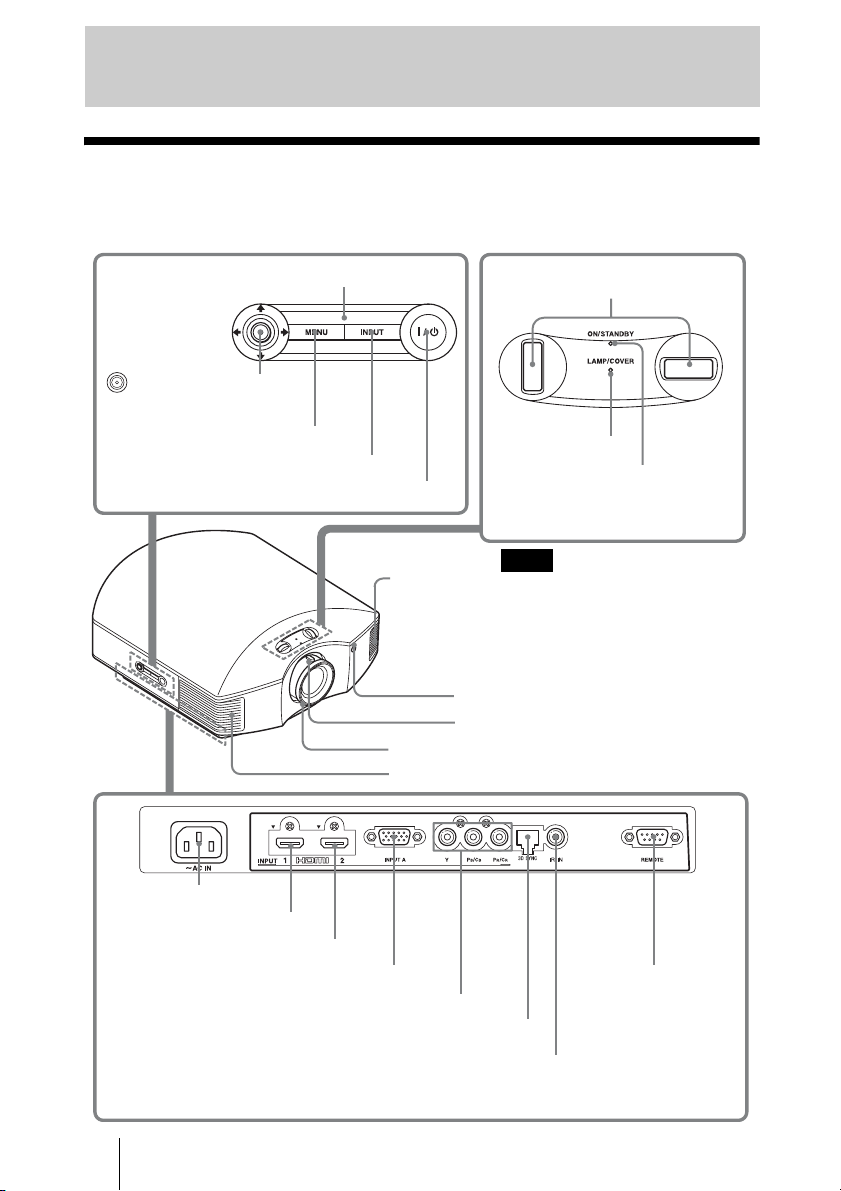
Location of Controls
Front/Right Side
You can use the buttons on the control panel with the same names as those on the remote
control to operate the projector.
M/m/</, (arrow)/
(enter) button (1 page 41)
MENU button (1 page 41)
INPUT button (1 page 27)
?/1 (ON/STANDBY) switch (1 page 17)
Control panel
Lens shift dials (1 page 17)
LAMP/COVER
indicator
(1 page 68)
Ventilation
holes (exhaust)
(1 page 14)
Focus ring (1 page 19)
Ventilation holes (exhaust) (1 page 14)
Note
While the ON/STANDBY indicator
lights in orange, the power saving
mode is on. (1 page 54)
Remote control detector
Zoom lever (1 page 19)
ON/STANDBY
indicator
(1 page 16)
- AC IN socket
HDMI 1 connector (1 page 21)
HDMI 2 connector (1 page 21)
Y P
B/CB PR/CR connector (phono type) (1 page 22)
GB
8
INPUT A connector (1 page 23)
3D SYNC connector (1 page 24)
REMOTE connector
Connects to a computer,
etc. for remote control
IR IN connector
Inputs signals to control the projector
Page 9

Rear/Bottom
Location of Controls
Ventilation holes (intake)
(1 page 14)
Ventilation holes (intake)
(1 page 14)
Ventilation holes (intake)
(1 page 14)
Ventilation holes (intake)
(1 page 14)
Lamp cover (1 page 72)
Front feet (adjustable) (1 page 20)
Filter holder (1 page 73)
Ventilation holes (intake)
(1 page 14)
Projector suspension
support attaching hole
(1 page 88)
3D Sync Transmitter
(1 page 34)
9
GB
Page 10

Remote Control
LIGHT button
Illuminates the buttons on
the remote control.
CALIBRATED PRESET
buttons (1 page 36)
Infrared transmitter
?/1 (On/standby)
switch (1 page 17)
INPUT button (1 page 27)
PATTERN button
(1 page 17)
MOTION ENHANCER
button (1 page 38)
ASPECT button
(1 page 29)
COLOR SPACE button
(1 page 38)
COLOR TEMP button
(1 page 38)
GAMMA CORRECTION
button (1 page 38)
SHARPNESS +/– button
(1 page 47)
RESET button (1 page 41)
M/m/</, (arrow)/ (enter)
buttons (1 page 41)
MENU button (1 page 41)
3D button (1 page 55)
RCP (Real Color Processing)
button (1 page 39)
REALITY CREATION
button (1 page 46)
ADVANCED IRIS
button (1 page 38)
CONTRAST +/– button
(1 page 47)
BRIGHTNESS +/– button
(1 page 47)
GB
10
Page 11

Connections and Preparations
This section describes how to install the projector and screen, how to connect the
equipment from which you want to project the picture, etc.
Unpacking
Check the carton to make sure it contains the following items:
• Remote control (1) and
Size AA (R6) manganese batteries (2)
Inserting the batteries into the remote control
Insert the batteries E side first as shown in the illustration.
Inserting them forcibly or with the polarities reversed may
cause a short circuit and may generate heat.
• AC power cord (1)
• Lens cap (1)
When you have purchased the projector,
the lens cap is put onto the lens.
Remove this lens cap when you use the
projector.
• 3D glasses (2)
• Pouch for the 3D glasses (2)
• USB charging cable (APY5244010020/
SONY) (1.2 m) (2)
• Conversion cable (LAN(M)-MD03(J)/
SONY) (18 cm) (1)
• Operating Instructions (this manual)
• Operating Instructions for the 3D
glasses (1)
Connections and Preparations
Push and slide to open.
CAUTION
Danger of explosion if battery is incorrectly replaced.
Replace only with the same or equivalent type recommended by the manufacturer.
When you dispose of the battery, you must obey the law in the relative area or country.
Installing batteries
Two size AA (R6) batteries are supplied for Remote Control.
To avoid risk of explosion, use size AA (R6) manganese or alkaline batteries.
11
GB
Page 12

Caution about handling the remote control
• Handle the remote control with care. Do not drop or step on it, or spill liquid of any kind
onto it.
• Do not place the remote in a location near a heat source, a place subject to direct
sunlight, or a damp room.
GB
12
Page 13

Step 1: Installing the Projector
The projector displays pictures output from
a VCR or other device.
The lens shift allows you to have broader
options for placing the projector and
viewing pictures easily.
Before Setting Up the
Projector
Unsuitable installation
Do not place the projector in the following
situations, which may cause malfunction
or damage to the projector.
Poorly ventilated location
Leave space of more than 30 cm (11 7/8 inches)
around the unit.
Hot and humid
Installing the projector in such a location
may cause a malfunction of the unit due to
moisture condensation or rise in
temperature.
Near a heat or smoke sensor
Malfunction of the sensor may occur.
Very dusty and extremely smoky
locations
Install in a location away from walls
To maintain the performance and
reliability of the projector, allow at
least 30 cm (11 7/8 inches) between
the projector and walls.
Connections and Preparations
Locations subject to direct cool or
warm air from an air-conditioner
(11
30 cm
7
/8inches)
30 cm
(11
7
/8inches)
(11 7/8inches)
(11
30 cm
30 cm
7
/8inches)
13
GB
Page 14

Improper use
Do not do any of the following while using
the projector.
Blocking the ventilation holes (intake
or exhaust)
Ventilation holes
(intake)
Ventilation holes
(exhaust)
Tip
For details on the location of the ventilation
holes (intake or exhaust), see “Location of
Controls” (1 page 8).
Tilting front/rear and left/right
15° or more
15° or more
15° or more
Avoid using the projector tilted at an angle
of more than 15 degrees.
Do not install the projector anywhere other
than on a level surface or on the ceiling.
Installing the projector in such a location
may result in uneven color uniformity or
reduce the reliability of the effects of the
lamp.
If the projector is tilted up or down, the
image on the screen may be trapezoidal.
Position the projector so that the lens is
parallel to the screen (1 page 15).
When installing the unit at altitudes
When using the projector at an altitude of
1,500 m or higher, set “Cooling Setting” in the
Setup menu to “High” (1 page 53).
Failing to set this mode when using the
projector at high altitudes could have adverse
effects, such as reducing the reliability of
certain components.
WARNING
When installing the unit, incorporate a readily
accessible disconnect device in the fixed
wiring, or connect the power plug to an easily
accessible socket-outlet near the unit. If a fault
should occur during operation of the unit,
operate the disconnect device to switch the
power supply off, or disconnect the power
plug.
15° or more
GB
14
15° or more
Safety precautions for
installing the unit on a ceiling
• Never mount the projector on the ceiling or
move it by yourself. Be sure to consult with
qualified Sony personnel (charged).
• When installing the unit on a ceiling, be sure
to use a safety wire, etc., to prevent the unit
from falling. Entrust the installation to an
experienced contractor or installer.
Page 15
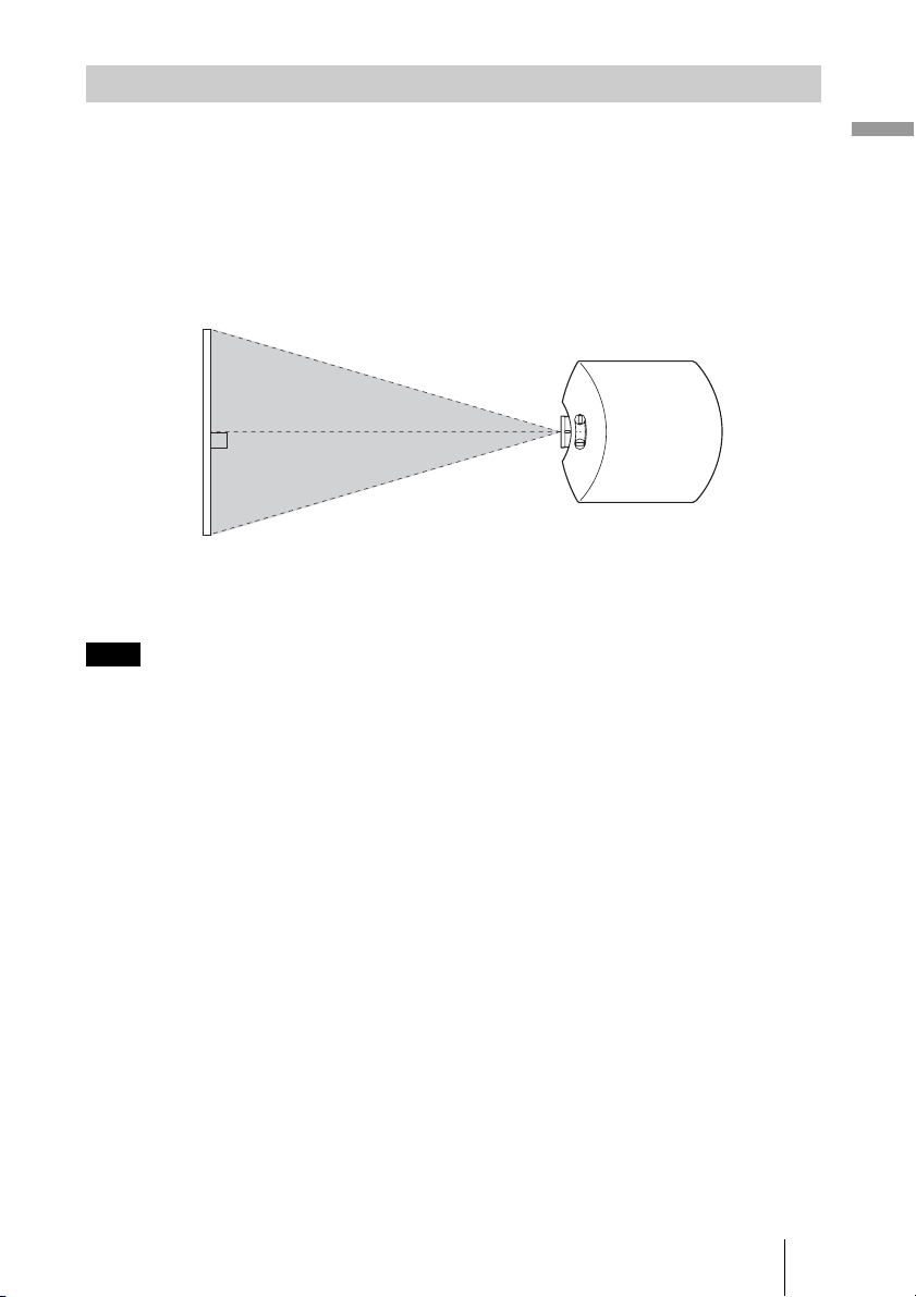
Installing the Unit
The installation distance between the unit and a screen varies depending on the size of the
screen or whether or not you use the lens shift features. Install this unit so that it fits the
size of your screen. For details on the distance between the unit and the screen (the
projection distance) and the size of projected video, see “Projection Distance and Lens
Shift Range” (1 page 86).
1 Position the unit so that the lens is parallel to the screen.
Top view
Screen
2 Project an image on the screen and adjust the picture so that it fits the
screen. (1 page 16)
Note
When using a screen with an uneven surface, stripes pattern may rarely appear on the screen
depending on the distance between the screen and the projector or the zooming magnifications. This
is not a malfunction of the projector.
Connections and Preparations
15
GB
Page 16

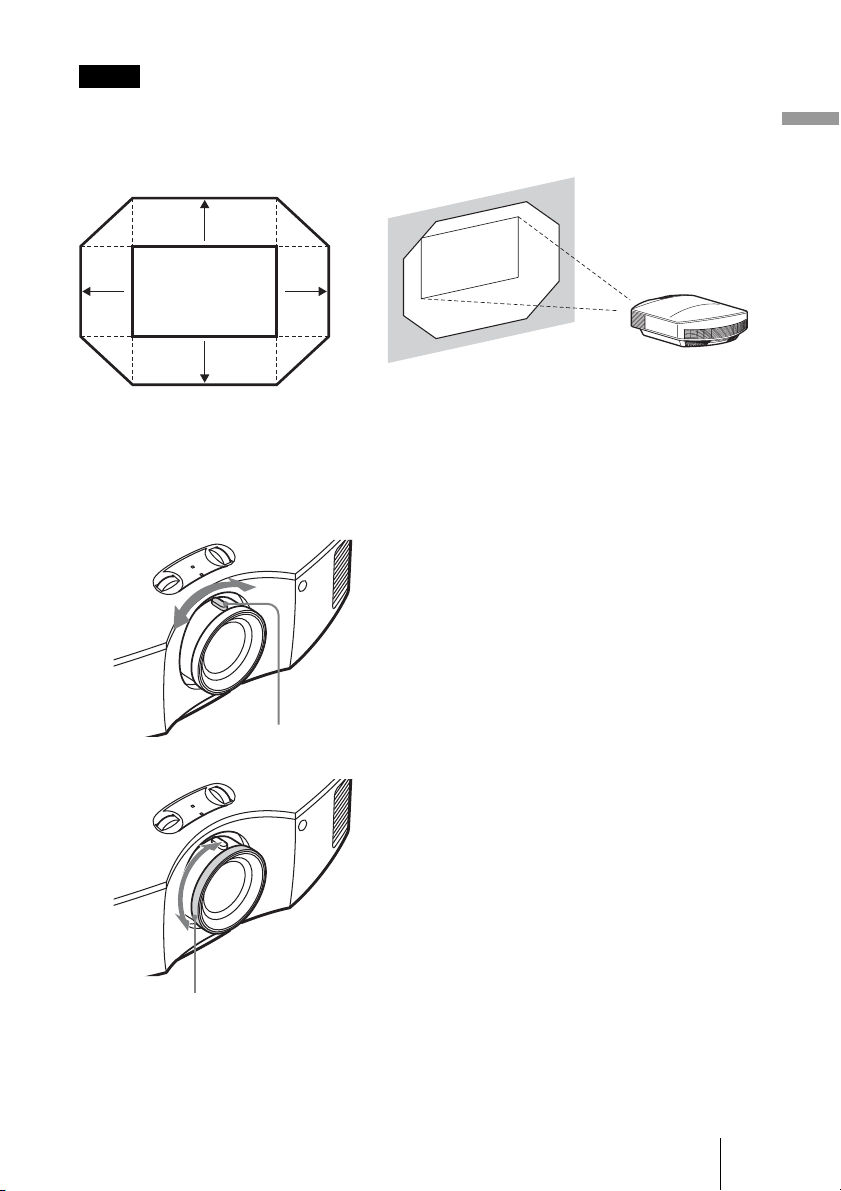
Step 2: Adjusting the Picture Position
Project an image on the screen and then adjust the picture position.
ON/STANDBY indicator
1
Lens shift dials
4
Remote control
detector
5, 6
Zoom lever,
Focus ring
2
?/1 (On/
standby)
switch
3 PATTERN button
Tip
The ?/1 (ON/STANDBY), INPUT, MENU, and M/m/</,/ (joystick) buttons on the side
panel of the projector function the same as those on the remote control.
Note
Depending on the installation location of the projector, you may not control it with the remote
control. In this case, point the remote control to the screen instead of the projector.
1 After connecting the AC cord to
the projector plug the AC cord
Lights in red.
into a wall outlet.
The ON/STANDBY indicator lights
in red and the projector goes into
standby mode.
GB
16
Page 17

Flashes in green fo
r
a while (tens of
seconds) and then
lights in green.
2 Press the ?/1 (ON/STANDBY)
switch to turn on the projector.
The ON/STANDBY indicator flashes
in green, and then lights in green.
3 Display a test signal for
performing adjustments.
Press the PATTERN button on the
remote control to display the test
signal.
Tip
Press the PATTERN button to clear the
test signal display.
4 Move both lens shift dials to
adjust the picture position.
Connections and Preparations
To adjust the vertical
position
To adjust the horizontal position
17
GB
Page 18

To adjust the horizontal position
Turn the lens shift dial right or left.
The picture projected on the screen moves right or left by a maximum of 25% of the screen
width from the center of the lens.
25% 1 screen width 25%
Top view
: Picture position when moving the picture to the left
at maximum
: Picture position when moving the picture to the
right at maximum
To adjust the vertical position
Turn the lens shift dial up or down.
The picture projected on the screen moves up or down by a maximum of 71% of the screen
height from the center of the lens.
Side view
GB
18
71%
1 screen
height
71%
: Picture position when moving the picture upward at
maximum
: Picture position when moving the picture downward at
maximum
Page 19
Notes
• The range to move the picture projected on the screen can be adjusted only within the octagon area
illustrated below. For details, see “Projection Distance and Lens Shift Range” (1 page 86).
Range of movement of
the projected picture
0.71V
Connections and Preparations
0.25H 0.25H
• When you use both the horizontal and vertical lens shift features at the same time, the distance the
Projected Picture
0.71V
H: Width of the projected picture
V: Height of the projected picture
picture projected on the screen moves differ depending on how much the lens shift is adjusted.
5 Adjust the picture size using the
zoom lever.
Zoom lever
6 Adjust the focus using the focus
ring.
Focus ring
19
GB
Page 20

To adjust the tilt of the installation surface
If the projector is installed on an uneven surface, use the front feet (adjustable) to keep the
projector level.
Turn to adjust.
Front feet (adjustable)
Notes
• Pointing the projector at too high or too low of a tilt will result in trapezoidal distortion in the
projected image.
• Be careful not to catch your finger when turning the front feet (adjustable).
Lens Focus adjustment window (test pattern)
4:3
GB
20
2.35:1
1.85:1
Page 21
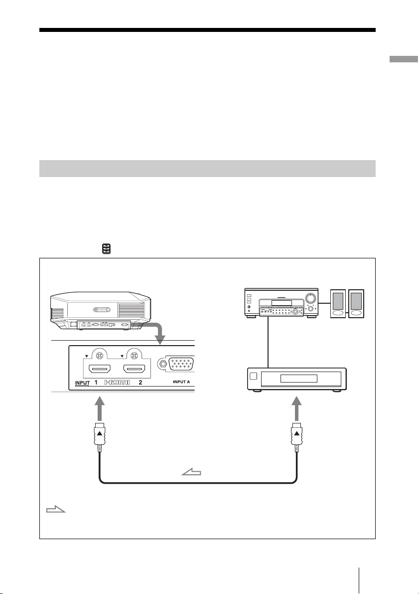
Step 3: Connecting the Projector
When making connections, be sure to do the following:
• Turn off all equipment before making any connections.
• Use the proper cables for each connection.
• Insert the cable plugs properly; poor connection at the plugs may cause a malfunction or
poor picture quality. When pulling out a cable, be sure to pull it out from the plug, not
the cable itself.
• Refer to the operating instructions of the connected equipment.
Connecting to a VCR
To connect to equipment with HDMI output connectors
You can enjoy better picture quality by connecting a DVD player/recorder, Blu-ray Disc
player/recorder, or PS3
Moreover, if you have a Control for HDMI compatible equipment, you can operate the
projector synchronizing with the Control for HDMI compatible equipment. For details,
see the Function menu (1 page 55) and “About the Control for HDMI” (1 page 63).
Right side of the projector
®
equipped with HDMI output to the HDMI input of the projector.
AV amplifier
Equipment with HDMI
output connectors
Speakers
Connections and Preparations
: Video signal flow
to HDMI output
HDMI cable (not supplied)
When using an HDMI cable, be sure to use a Sony HDMI
cable or another cable that has the HDMI logo.
21
GB
Page 22

Notes
• Use a high-speed HDMI cable. With a standard HDMI cable, images of 1080p, DeepColor, and
3D video images may not be displayed properly.
• When connecting an HDMI cable to the projector, make sure the
HDMI input of the projector and the
v mark on the connector of the cable is set at the same
V mark on the upper part of the
position.
• If the picture from equipment connected to the projector with an HDMI cable is not clear, check
the settings of the connected equipment.
To connect to equipment with component video output
connectors
Right side of the projector
Component video cable (not supplied)
: Video signal flow
AV amplifier
Equipment with component
video output connectors
Speakers
GB
22
Page 23

Connecting to a Computer
Right side of the projector
Computer
to monitor output
HD-Dsub15 pin cable (not supplied) or HDMI cable (not supplied)
: Video signal flow
Notes
When using an HDMI cable, be sure to use a Sony HDMI
cable or another cable that has the HDMI logo.
• Use a high-speed HDMI cable. With a standard HDMI cable, images of 1080p, DeepColor, and
3D video images may not be displayed properly.
• When connecting an HDMI cable, make sure the
V mark on the upper part of the HDMI input of
the projector and the v mark on the connector of the cable is set at the same position.
• If you set your computer, such as a notebook type, to output the signal to both computer’s display
and this equipment, the picture of the equipment may not appear properly. Set your computer to
output the signal to only the external monitor.
For details, refer to the computer’s operating instructions supplied with your computer. For
settings of the computer, consult with the manufacturer of the computer.
• If the picture from equipment connected to the projector with an HDMI cable is not clear, check
the settings of the connected equipment.
Connections and Preparations
23
GB
Page 24

Connecting to a 3D Sync Transmitter
This unit incorporates a 3D Sync Transmitter. Depending on the installation environment
of the unit, the 3D glasses may not receive 3D signals properly from the unit’s built-in 3D
Sync Transmitter. In this case, connect an optional 3D Sync Transmitter and place it near
your viewing position.
Right side of the projector
Connecting cable
: 3D sync signal flow
Tip
Place the optional 3D Sync Transmitter directly facing the 3D glasses. Also, in order to stabilize
operation of the 3D glasses, it is recommended that you place the 3D Sync Transmitter near your
viewing position.
3D Sync Transmitter
(not supplied)
CAUTION
Be sure to use straight-type LAN cable of up to 15 m labeled TYPE CM, and do not use
an extension cord.
Notes
• The 3D SYNC connector is dedicated for the optional 3D Sync Transmitter. Do not connect
computers or other network devices, to avoid malfunction.
• You can use a 3D Sync Transmitter separate from this unit, using an optional LAN cable (straighttype).
If the usage environment has interference of a continuous specific frequency, synchronization of
3D image signals and the 3D glasses may be lost. In this case, use a LAN cable labeled Category 7.
When watching 3D images in an environment that has even more interference, use the internal
transmitter.
• Be sure to use cable of up to 15 m, and do not use an extension cord. Also, keep the LAN cable
away from any AC power cords as much as possible.
• Only one 3D Sync Transmitter should be connected to the unit. Connecting multiple 3D Sync
Transmitters may cause a malfunction.
• When connected to the 3D Sync Transmitter, the built-in 3D Sync Transmitter feature of the unit
will turn off. You cannot use both at the same time.
GB
24
Page 25

Step 4: Selecting the Menu Language
You can select one of 16 languages for displaying the menu and other on-screen displays.
The factory default setting is English. To change the current menu language, set the
desired language with the menu screen.
2,3,4
M/m/</,
(arrow)/ (enter)
buttons
1
MENU button
1 Press MENU.
The menu appears.
Connections and Preparations
25
GB
Page 26

2 Press M/m to select the
Setup menu, and press , or
.
The setting items of the selected menu
appear.
3 Press M/m to select “Language,”
and press , or .
GB
4 Press M/m/</, to select a
language, and press .
The menu changes to the selected
language.
To clear the menu
Press MENU.
26
Page 27

Projecting
This section describes how to operate the unit to view the picture from the equipment
connected to the unit. It also describes how to adjust the quality of the picture to suit your
taste.
Projecting the Picture
1 Power on both the projector and
the equipment connected to the
unit.
2 Press INPUT to display the input
palette on the screen.
3 Select the equipment from
which you want to display
images.
Example: To view the picture
from the video
equipment connected
to the HDMI 1
connector of this unit.
To view the picture from Press INPUT to display
RGB equipment connected to the INPUT A connector Input-A
Component equipment connected to the Y P
Equipment connected to the HDMI 1 connector HDMI 1
Equipment connected to the HDMI 2 connector HDMI 2
B/CB PR/CR connector Component
Press INPUT repeatedly or press M/m/
(enter) to select the equipment
from which to project.
Projecting
Tips
• When “Auto Input Search” is set to “On” in the Function menu, only input terminals with
effective signals are displayed in the input palette.
• When “Status” is set to “Off” in the Setup menu, the input palette does not appear. Press of
the INPUT button to switch between input terminals in sequence.
• When the “Control for HDMI” is set to “On” in the Function menu, the input terminal with
effective signals is automatically displayed, synchronizing with the operation of the equipment
connected to HDMI 1 or HDMI 2 input of the unit. (Only when the connected equipment supports
Control for HDMI compatible.)
27
GB
Page 28

Turning Off the Power
1 Press the ?/1 (ON/STANDBY) switch.
A message “POWER OFF?” appears on the screen.
2 Press the ?/1 (ON/STANDBY) switch again before the message
disappears.
The ON/STANDBY indicator flashes in green and the fan continues to run to reduce
the internal heat. First, the ON/STANDBY indicator flashes quickly, during which
you will not be able to light up the lamp with the
The fan stops and the ON/STANDBY indicator changes from flashing green to
remaining red.
The power is turned off completely, and you can disconnect the power cord.
Note
Never disconnect the power cord while the indicator is flashing.
You can turn off the projector by holding the ?/1 (ON/STANDBY) switch for about 1
second, instead of performing the above steps.
?/1 (ON/STANDBY) switch.
GB
28
Page 29

Selecting the Aspect Ratio According to the
Video Signal
You can select an aspect ratio best suited for the video signal received.
Press ASPECT.
Each time you press the button, you can
select the “Aspect” setting.
You can also select it using the menu.
ASPECT button
Original image Recommended setting and resultant images
1.33:1 (4:3)
(1 page 51)
Wide Zoom (When an SD signal is input)
Projecting
1.33:1 (4:3) with side panels
1.33:1 (4:3) letterbox picture
Zoom (When an SD signal is input)
29
GB
Page 30

Original image Recommended setting and resultant images
Normal
1.78:1 (16:9)
1.33:1 (4:3)
1.33:1 (4:3) with side panels
Stretch
Squeezed
GB
V Stretch
2.35:1
When using an anamorphic lens
30
Page 31

Original image Recommended setting and resultant images
Squeeze
16:9
When using an anamorphic lens
Normal (When a computer signal is input)
Full (When a computer signal is input)
Projecting
Notes
• Selectable aspect modes vary depending on the input signal.
• You can adjust the vertical position of the picture with “V Center” and “Vertical Size” in the
Screen menu only when “Aspect” is set to “Zoom.” (1 page 52)
Notes on switching the “Aspect” setting
• Select the aspect mode taking into account that changing the aspect ratio of the original
picture will provide a different look from that of the original image.
• Note that if the unit is used for profit or for public viewing, modifying the original
picture by switching the aspect may constitute an infringement of the rights of authors
or producers, which are legally protected.
31
GB
Page 32

Watching 3D Video Images
You can enjoy powerful 3D video images, such as from 3D games and 3D Blu-ray Discs,
using the supplied 3D glasses.
1 Turn on the HDMI equipment for 3D compatibility connected to the unit,
then play the 3D content.
For details on how to play 3D content, refer to the operating instructions for the
connected equipment.
2 Turn on the unit and project the 3D video image onto the screen.
For details on how to project the image, see “Projecting the Picture” (1 page 27).
3 Turn on the 3D glasses, and then put them on so that they fit
comfortably.
For details on how to use the 3D glasses, see “Using the 3D Glasses” (1 page 33).
Tips
• The factory default setting for “2D-3D Display Sel.” is “Auto.” to allow projecting 3D video
images automatically when the projector detects 3D signals.
• To convert 3D video images to 2D video images, set “2D-3D Display Sel.” to “2D” (1 page 55).
Notes
• It may not be possible to display 3D video image, depending on the type of signal. Set the “2D-3D
Display Sel.” to “3D,” and “3D Format” to “Side-by-Side” or “Over-Under” to suit the format of
the 3D content you want to watch (1 page 55).
• Use the 3D glasses within the communication range (1 page 34).
• You can watch 3D video images only when signals from HDMI input. When connecting 3D
equipment such as a 3D game or 3D Blu-ray player to the unit, use an HDMI cable.
• There are differences in perception of 3D video images among individuals.
• When the temperature of the usage environment is low, the 3D effect may be diminished.
Adjusting/Setting the 3D functions using the menu
Press the 3D button on the remote control to adjust the 3D settings in “3D Settings” in the
Function menu. For details, see “3D Settings” (1 page 55).
GB
32
Page 33

Using the Simulated 3D Function
You can convert normal 2D video images to 3D video images.
Tip
For details on how to operate the on-screen menu, see “Operation through the Menus” (1 page 41).
1 Display the Function menu and select “3D Settings.”
2 Set “2D-3D Display Sel.” to “3D,” then press , to display “3D Format.”
3 Set “3D Format” to “Simulated 3D” (1 page 55).
Tip
Use the supplied 3D glasses.
Notes
• “2D-3D Display Sel.” cannot be set to “3D” for some video sources. For available 3D signals, see
“Compatible 3D Signals” (1 page 81).
• The simulated 3D feature may have limited effect, depending on the video source.
• There are differences in perception of 3D video images converted by the simulated 3D function
among individuals.
Using the 3D Glasses
The 3D glasses receive signals sent by the 3D Sync Transmitter built into the front of the
unit, which are reflected to the glasses from the screen. When watching 3D video images
using the 3D glasses, face squarely toward the screen.
Projecting
LED indicatorPower button
1 Press the power button on the
3D glasses.
The LED indicator lights up in green.
2 Put on the 3D glasses.
3 Turn toward the screen.
IR sensor
Precautions for use
The 3D glasses receive infrared signals sent by the 3D Sync Transmitter built into the front
of the unit, which are reflected to the glasses from the screen.
Misoperation may occur if:
• The 3D glasses do not face the screen
• There are objects blocking the path between the 3D glasses and the screen
• The viewing position is too far from the screen or the distance between the unit and
screen is too great
33
GB
Page 34

• There are other infrared communication devices nearby
3D glasses communication range
Figures A and B below indicate the communication range of the 3D glasses. If you try to
watch 3D video images from a distance greater than the communication range or install
the projector outside the communication range, the 3D glasses may not be able to display
the images properly. Also, the viable angles and distance vary depending on the screen
type, environment of the room, and installation environment of the projector.
Figure A: 3D glasses communication range (distance from the screen)
Approx. 5 m (Maximum)
Screen
3D glasses
Top or side view
Figure B:3D sync signal communication distance between the projector
and screen
Approx. 5 m (Maximum)
Projector
Side view
Screen
Note
A 3D sync signal is projected towards the screen from 3D Sync Transmitter at the front of this unit.
(Figure C)
Installation conditions may prevent 3D sync signals from reaching the screen; for example, an
obstruction in front of the unit.
GB
34
Page 35

Figure C
Installation A
3D Sync Transmitter
: 3D sync signal is blocked.
Installation B
When projecting downward from a unit that is recessed, if the unit is not installed on the
ceiling, the signal from the 3D Sync Transmitter may not be projected properly to the
screen, and the 3D glasses will not operate normally. (Installation A)
Install the unit with its lens at the edge of, or outside of, the recess (Installation B).
Alternatively, use the optional 3D Sync Transmitter. (1 page 24)
Projecting
35
GB
Page 36

Selecting the Picture Viewing Mode
You can select the picture viewing mode that best suits the type of video source or room
conditions.
You can save and use different preset modes for 2D/3D respectively.
Press one of the CALIBRATED PRESET buttons.
CALIBRATED
PRESET buttons
Setting items Description
CINEMA FILM 1 Picture quality suited to reproducing the highly dynamic and clear images
CINEMA FILM 2 Picture quality suited to reproducing the rich tone and color typical of a
REF A picture quality setup suitable for when you want to reproduce faithfully
TV Picture quality suited for watching TV programs, sports, concerts, etc.
PHOTO Ideal for projecting still images taken with a digital camera.
GAME Picture quality suited to gaming, with well-modulated colors and fast
BRT CINE Picture quality suited for watching movies in a bright environment, such
BRT TV Picture quality suited for watching TV programs, sports, concerts, and
USER Adjusts the picture quality to suit your taste then saves the setting. The
typical of master positive film.
movie theater.
the original image quality, or for enjoying image quality, without any
adjustment.
response.
as a living room.
other video images in a bright environment, such as a living room.
factory default setting is the same as “REF.”
GB
36
Page 37

Using “ImageDirector3” to Adjust the Picture
Quality
By using the “ImageDirector3,” you can make the desired gamma correction from a
computer connected to the unit. Connect the REMOTE connector of the unit with a
computer and start-up “ImageDirector3” on the computer.
For details on how to use “ImageDirector3,” refer to the Help in “ImageDirector3.”
Notes
• You need to install the “ImageDirector3” on a computer beforehand. “ImageDirector3” can be
downloaded from the Sony website.
http://esupport.sony.com/US/p/select-system.pl
http://www.pro.sony.eu/pro/article/projectors-home-cinema-article
• When connecting the REMOTE connector with a computer, connect while the power of the
computer and the unit is off.
• You cannot adjust the picture quality when “Gamma Correction” in the Picture menu is set to
“Off”.
• When you set “Gamma Correction” in the Picture menu to 1.8, 2.0, 2.1, 2.2, 2.4, or 2.6,
“ImageDirector3” displays Gamma 1, Gamma 2, Gamma 3, Gamma 4, Gamma 5, or Gamma 6,
respectively.
• If you use “ImageDirector3” while a 3D video image is displayed or a 3D signal is input, the image
may be distorted.
Projecting
37
GB
Page 38

Adjusting the Picture Quality
You can easily adjust the picture quality that suits your taste by selecting the adjustment
items with the remote control. The adjusted data can be stored in each calibrated preset
mode.
Selecting to Directly Adjust the Desired Menu Item
The following menu items can be
MOTION
ENHANCER button
COLOR TEMP
button
COLOR SPACE
button
REALITY
CREATION button
ADVANCED IRIS
button
GAMMA
CORRECTION
button
adjusted by using the buttons on
the remote control.
“Motion Enhancer”
“Color Temp.”
“Color Space”
“Advanced Iris”
“Reality Creation”
“Gamma Correction”
Press the following buttons of the desired
menu item repeatedly to adjust the picture
quality to suit your taste. For details on
each menu item, see the Picture menu.
(1 page 45)
GB
38
Page 39

Adjusting the Picture Using Real Color
Processing
The Real Color Processing (RCP) feature allows you to adjust the color, hue, and
brightness of each target of the projected picture you specify independently. You can thus
obtain a picture more suitable to your taste.
Tip
Freeze the scene of the video source when you are adjusting the picture using Real Color Processing.
1 Press RCP on the remote
control.
2, 3, 4, 5
M/m/</,
(arrow) /
(enter) buttons
1, 6
RCP (Real
Color
Processing)
button
Reference palette
2 Press M/m to select “User 1,”
“User 2” or “User 3,” then press
,.
The RCP (Real Color Processing)
window appears.
3 Select the target color you want
to adjust.
Repeat steps 1 and 2 described
below to specify the target color.
1 Press
M/m to select
“Color Select,” then press
to select the color you want to
adjust among “Red,” “Yellow,”
“Green,” “Cyan,” “Blue” and
“Magenta.”
Only the portions that correspond
to the specified color will be
colored and the other portions will
be displayed in black and white.
The reference palette in the RCP
window also shows the adjustable
colors. Select the desired setting to
adjust the color on the projected
image using the reference palette
as a guide.
</,
Projecting
39
GB
Page 40

2 Press M/m to select “Position” or
“Range,” and specify it more
delicate color position and color
range you want to adjust using
</,.
4 Adjust the color of the specified
portions.
Press
M/m to select “RCP Color,”
“RCP Hue” or “RCP Brightness,”
then adjust the color or hue of the
portions selected in step 3 to suit your
taste using
projected picture. The picture is
returned to normal color during
adjustment.
</, while watching the
5 After the adjustment is
complete, press .
The RCP window disappears and the
picture of step 2 returns.
Tip
There are some limitations on selection of
position and range.
6 Press RCP.
GB
40
Page 41

Using the Menus
This section describes how to make various adjustments and settings using the menus.
Note
The menu displays used for the explanation may be different from the actual menu display.
Operation through the Menus
The projector is equipped with an on-screen menu for making various adjustments and
settings. Some of the adjustable/setting items are displayed in a pop-up menu, in a setting
menu or adjustment menu with no main menu, or in the next menu window. If you select
an item name followed by an arrow (
To change the on-screen menu language, see “Step 4: Selecting the Menu Language.”
(1 page 25)
B), the next menu window with setting items appears.
Using the Menus
RESET button
2, 3, 4
M/m/</, (arrow) /
(enter) buttons
1
MENU button
41
GB
Page 42

1 Press MENU.
The menu window appears.
2 Press M/m to select a menu item,
and press , or .
The items that can be set or adjusted
with the selected menu appear. The
item presently selected is shown in
white.
GB
42
Page 43

Pop-up menu
Setting menu
3 Press M/m to select an item you
want to set or adjust and press
, or .
The setting items are displayed in a
pop-up menu, in a setting menu, in an
adjustment menu or in the next menu
window.
Setting items
Using the Menus
Adjustment menu
Next menu window
Setting items
43
GB
Page 44

4 Make the setting or adjustment
of an item.
When changing the adjustment
level
To increase the value, press M/,.
To decrease the value, press m/<.
Press to restore the original screen.
When changing the setting
Press M/m to change the setting.
Press to restore the original screen.
You can restore the original menu
screen using < depending on the
selected item.
Items that cannot be adjusted
Adjustable items differ depending on the
input signal. The items that cannot be
adjusted or set do not appear in the menu.
(1 page 79)
To clear the menu
Press MENU.
To reset the picture that has
been adjusted
Select “Reset” from Picture menu.
To reset the items that have
been adjusted
Select an item in the Menu screen, and
display the pop-up menu, the setting
menu, and the adjustment menu.
Press the RESET on the remote control to
reset only the selected settings to its
factory preset value.
Note
RESET button on the remote control is
available only when the adjustment menu or
the setting menu is selected.
When the screen display appears, select
“Yes” using < and press .
All of the following settings are reset to its
factory preset value.
The settings of “Reality Creation,”
“Cinema Black Pro,” “Motionflow,”
“Contrast,” “Brightness,” “Color,”
“Hue,” “Color Temp,” “Sharpness” and
“Expert Setting” on the Picture
GB
44
menu
Page 45

Picture Menu
The Picture menu is used for adjusting the picture.
Note
These items may not be available, depending on the type of input signal. For details, see “Input
Signals and Adjustable/Setting Items” (1 page 79).
Item names in brackets represent those printed on the remote control.
Using the Menus
Calib. Preset
[CALIBRATED PRESET]
Reset Resets all currently selected Calib. Preset mode settings to their default
You can select the picture viewing mode that best suits the type of
video source or the environment.
You can save and use different preset modes for 2D/3D respectively.
Cinema Film 1: Picture quality suited to reproducing the highly
dynamic and clear images typical of master positive film.
Cinema Film 2: Picture quality suited to reproducing the rich tone and
color typical of a movie theater.
Reference: A picture quality setup suitable for when you want to
reproduce faithfully the original image quality, or for enjoying image
quality, without any adjustment.
TV: Picture quality suited for watching TV programs, sports, concerts,
etc.
Photo: Ideal for projecting still images taken with a digital camera.
Game: Picture quality suited to gaming, with well-modulated colors and
fast response.
Bright Cinema: Picture quality suited for watching movies in a bright
environment, such as a living room.
Bright TV: Picture quality suited for watching TV programs, sports,
concerts, and other video images in a bright environment, such as a
living room.
User: You can adjust the picture quality to suit your taste, and save the
setting. The factory default setting is the same as “Reference.”
Tip
Any adjustments to picture quality settings are saved for each input.
values (1 page 44).
Tip
Reset does not affect settings saved for the Custom 1 to 5 items of
“Color Temp.” To reset Gain or Bias in Custom 1 to 5, use the RESET
button on the remote control on the Gain or Bias setting screen.
45
GB
Page 46

Reality Creation
[REALITY CREATION]
Cinema Black Pro Advanced Iris [ADVANCED IRIS]
Motionflow Film Projection
Adjusts the detail and noise processing of images. (Super-resolution
function)
On: Applies detail and noise processing effects.
Resolution: When you increase the setting value, the texture and
detail of the picture become sharper.
Noise Filtering: When you increase the setting value, the noise
(picture roughness) becomes less prominent.
Test: On/Off: Changes “On” and “Off” at a certain frequency to
check the effect of “Reality Creation.”
Tip
The display position of status during the test works together with the
“Menu Position” (1 page 53) setting.
Off: The “Reality Creation” function is not applied.
Switches the iris function.
Auto Full: Automatically adjusts to optimize the iris aperture according
to the brightness level of the input source. Moreover, signal
processing, which optimizes gradation expression between the peak
light and dark parts, expresses a large dynamic range. This results in a
bright and high contrast image.
Auto Limited: A lower brightness than Auto Full, making the image
suitable for viewing in a dark room.
Manual: Manually (fixed) adjusts the iris.
Off: Disables the iris (aperture) function.
Lamp Control
Switches the lamp output.
High: Increases the brightness, and projects brighter images.
Low: Decreases the brightness, and enhances blacks by minimizing
brightness.
Tip
Setting “Low” reduces fan noise, while also reducing energy
consumption for longer lamp life.
Reproduces an image similar to that of projected film.
Use this setting as preferred, based on the image content.
On: Reduces afterimage.
Off: The reduction effect of afterimage is less than the “On” setting. The
picture will become brighter.
Motion Enhancer [MOTION ENHANCER]
Reproduces fast-moving pictures smoothly without generating
afterimages.
High: Select this for picture quality smoother than “Low.”
Low: Select this for smooth picture quality.
Off: Select this to not apply the motion enhancer function.
Tip
Certain scenes may contain digital signal artifacts. In this case, set this
function to “Off.”
GB
46
Page 47

Contrast
[CONTRAST]
Brightness
[BRIGHTNESS]
Color Adjusts the color density.
Hue Adjusts the color tone.
Color Temp.
[COLOR TEMP]
Sharpness
[SHARPNESS]
Adjusts the contrast.
Higher values increase the sharpness in images, while lower values
decrease the sharpness.
You can make adjustments by pressing the CONTRAST +/– on the
remote control.
Adjusts the brightness of the picture.
The higher the setting, the brighter the picture. The lower the setting, the
darker the picture.
You can make adjustments by pressing the BRIGHTNESS +/– on the
remote control.
The higher the setting, the greater the intensity. The lower the setting, the
lower the intensity.
The higher the setting, the more greenish the picture becomes. The lower
the setting, the more reddish the picture becomes.
Adjusts the color temperature.
D93: Equivalent to 9,300 K color temperature normally used in TVs.
Gives white colors a blue tint.
D75: Equivalent to 7,500 K color temperature used as an ancillary
standard illuminant.
Gives a neutral tint between “D93” and “D65.”
D65: Equivalent to 6,500 K color temperature used as a standard
illuminant.
Gives white colors a red tint.
D55: Equivalent to 5,500 K color temperature used as an ancillary
standard illuminant.
Gives white colors an even redder tint.
Custom 1 to 5: Enables you to adjust, set, and store your favorite color
temperature. You can adjust Gain and Bias of RGB.
The factory default settings are as follows.
Custom 1: Same as “D93” color temperature setting.
Custom 2: Same as “D75” color temperature setting.
Custom 3: Same as “D65” color temperature setting.
Custom 4: Same as “D55” color temperature setting.
Custom 5: Setting that prioritizes brightness.
Sharpens the outline of the picture, or reduces the noise.
The higher the setting, the sharper the picture. The lower the setting, the
softer the picture, thus reducing the noise.
You can make adjustments by pressing the SHARPNESS +/– on the
remote control.
Using the Menus
47
GB
Page 48

Expert Setting NR (Noise Reduction)
Reduces the roughness or noise of the picture.
Usually, use to select “Off.”
If the picture is rough or noisy, select a setting from among “Low,”
“Middle” or “High” according to the input signal source.
MPEG NR (MPEG Noise Reduction)
Reduces block noise and mosquito noise, in particular in digital
signals.
Usually, use to select “Off.”
If the picture is rough or noisy, select a setting from among “Low,”
“Middle” or “High” according to the input signal source.
Film Mode
According to the film source you have selected, make a setting for
playback.
Auto 1: Suitable for reproducing the original picture movement.
Normally, set this to “Auto 1.”
Auto 2: Reproduces a 2-3 or 2-2 Pull-Down format video signal, such as
film sources, in a smooth picture movement. When a video signal
other than 2-3 or 2-2 Pull-Down format is input, the picture is played
back in progressive format.
Off: Plays back the picture in progressive format without detecting
video signals automatically.
Contrast Enhancer
Corrects the level of bright and dark parts automatically to optimize
contrast according to a scene.
Increases image sharpness and makes image dynamic.
High/Middle/Low: You can adjust the contrast enhancer.
Off: The contrast enhancer function is not applied.
Gamma Correction [GAMMA CORRECTION]
Adjusts the response characteristics of the tone of the picture.
Select a favorite tone from 10 options.
1.8: Bright Produces a brighter picture overall.
2.0
2.1
2.2
2.4
2.6: Dark Produces a darker picture overall.
Gamma 7: Simulates the gamma curve of film.
Gamma 8: Increases the sharpness in images. Select this when you
watch in a bright environment, such as a living room.
Gamma 9: Produces a brighter picture than Gamma 8.
Gamma 10: Increases the sharpness in images. Select this when you
watch TV programs, etc., in a bright environment, such as a living
room.
Off: Gamma Correction is not applied.
Using the specified controller, “ImageDirector3” (1 page 37) allows
you to adjust, set, and store a favorite tone in a computer.
For details on how to use “ImageDirector3,” refer to the Help in
“ImageDirector3.”
GB
48
Page 49

Expert Setting x.v.Color
Set this item when playing back an x.v.Color video signal.
Set this item to “On” when connecting the unit with equipment that
supports x.v.Color and playing back an x.v.Color video signal.
For details on x.v.Color, see “About the x.v.Color” (1 page 64).
Tip
Setting x.v.Color to “On” disables gamma adjustment.
Color Space [COLOR SPACE]
Converts the color space.
BT.709: An ITU-R BT.709 color space, which is used for high-
definition television broadcast or Blu-ray Disc. The color space is
equivalent to sRGB.
Color Space 1: The color space suited for watching TV programs and
video images, such as sport, concerts, etc.
Color Space 2: The color space suited for watching TV programs, sport,
concerts, and other video images in a bright environment, such as a
living room.
Color Space 3: The color space suited for watching movies.
Using the Menus
49
GB
Page 50

Advanced Picture Menu
The Advanced Picture is used for adjusting the picture more.
RCP (Real Color
Processing)
You can adjust the color, hue, and brightness of each selected
portion of the picture independently.
User 1, User 2, User 3: You can adjust the picture using Real Color
Processing and store the settings. Once the settings are stored, you can
view the picture with the adjusted picture quality.
Off: Cancels this feature.
For details, see “Adjusting the Picture Using Real Color Processing”.
(1 page 39)
GB
50
Page 51

Screen Menu
The Screen menu is used to adjust the input signal. You can adjust the size of the picture,
and select aspect mode, etc.
.
Note
These items may not be available, depending on the type of input signal. For details, see “Input
Signals and Adjustable/Setting Items” (1 page 79).
Item names in brackets represent those printed on the remote control.
Using the Menus
Aspect [ASPECT] Sets the aspect ratio of the picture to be displayed for the current
input signal. (1 page 29)
Wide Zoom: A 4:3 aspect ratio picture is projected naturally to fill the
screen. The upper and lower portions of the picture are cropped.
Zoom: A 4:3 aspect ratio picture is enlarged vertically and horizontally
in the same ratio to fill the screen. The upper and lower portions are
cropped. This mode is suitable to view a letterbox picture.
If a movie subtitle, etc., at the bottom of the picture cannot be seen, it
can be displayed by adjusting “Vertical Size” or “V Center.” (1 page
52)
Normal: Displays a picture on the whole of the screen, maintaining the
aspect ratio of the input picture. This is suitable for 16:9 or 4:3
pictures.
Stretch: A picture squeezed to 4:3 is displayed in 16:9 aspect ratio.
V Stretch: A 2.35:1 picture is displayed after having been changed to
16:9. This is the most suitable mode when using a commercially
available anamorphic lens.
Squeeze: Displays in its original aspect ratio when a 16:3 or 4:3 picture
is viewed using a commercially available anamorphic lens.
Full: Displays an original picture on the whole of the screen. Only when
a computer signal is input.
Notes
• When a computer signal is input, you can only select “Normal” and
“Full.”
• When the input is a 3D signal or when “2D-3D Display Sel.” in the
Function menu is set to “3D”, you can only select “Normal” or
“Squeeze.”
51
GB
Page 52

Over Scan Hides the edges of the picture.
Screen Area Selects the size of the picture when a Hi-Vision picture is
V Center Adjust the whole picture by moving up and down on the screen.
Vertical Size Reduces or enlarges the picture vertically.
Adjust Signal You can adjust the input signal.
On: The edges of the input picture are not displayed. Select this setting
when noise appears along the edge of the picture.
Off: Projects the whole of the input picture.
Tip
To display the displayable region within the four directions of the screen,
refer to “Blanking” on the Installation menu (1 page 59).
overscanned.
Full: Expands the picture on the whole of the screen.
Through: Does not expand the picture on the whole of the screen.
As the selected number increases, the screen moves up, and as the
selected number decreases, the screen moves down.
The screen is enlarged as the setting increases and reduced as the setting
decreases. If the subtitle of a movie, etc. cannot be seen, use this together
with “V Center”.
APA: Adjusts “Phase”, “Pitch”, and “Shift” automatically to a position
that suits the image signal for pictures from a computer.
Phase: Adjusts the dot phase and the phase of computer signal of
pictures from a computer. Adjusts the picture to the point where it
looks clearest.
Pitch: Adjusts the horizontal size of the picture from a computer.
As the number increases, the picture becomes wider, and as the
number decreases, the picture becomes narrower. Adjust the setting to
match the number of dots of the input signal.
Shift: Adjusts the position of the picture.
H: As the setting for H (horizontal) increases, the picture moves
to the right, and as the setting decreases, the picture moves to
the left. Use < / , to adjust the horizontal position.
V: As the setting for V (vertical) increases, the picture moves up,
and as the setting decreases, the picture moves down. Use M /
m to adjust the vertical position.
GB
52
Page 53

Setup Menu
The Setup menu is used to change the factory preset settings, etc.
Using the Menus
Status Sets whether or not the on-screen display is displayed.
Language Selects the language used in the menu and on-screen displays.
Menu Position You can change the position to display the menu on the upper
Cooling Setting Use this item when using the projector at high altitudes.
Standby Mode Lowers the power consumption in standby.
Set to “Off” to turn off the on-screen displays except for certain
menus, message when turning off the power, and warning messages.
Available languages are: English, Dutch, French, Italian, German,
Spanish, Portuguese, Russian, Swedish, Norwegian, Japanese,
Chinese (Simplified Chinese), Chinese (Traditional Chinese),
Korean, Thai and Arabic.
screen.
Bottom Left: Displays the menu on the bottom left area of the
screen.
Center: Displays the menu on the center of the screen.
High: Use this setting when using the projector at an altitude of
1,500 m or higher.
Standard: Use this setting when using the projector at normal
altitudes.
Note
When this item is set to “High”, the fan noise becomes slightly
louder since the number of fan rotations increase.
When set to “Standard”, the power consumption in standby becomes
normal.
When set to “Low”, the power consumption in standby is lowered.
Note
When this item is set to “Low”, the “PJ Auto Power On” function is
disabled (The function is set to “Off” and does not appear in the
menu.). (1 page 56)
53
GB
Page 54

Power Saving Sets the power saving mode.
Lamp Cutoff: The lamp turns off automatically and power
consumption is reduced if no signal is input for 10 minutes. If
signal is resumed, or any button on the control panel or remote
control is pressed, the lamp will light again. In Lamp Cutoff, the
ON/STANDBY indicator lights in orange. (1 page 8)
Standby: The power will be turned off automatically and the
projector goes to Standby mode if no signal is input for 10
minutes.
Off: The Power Saving mode is released.
Lamp Setting When replacing the lamps, set the desired lamp setting.
(1 page 73)
GB
54
Page 55

Function Menu
The Function menu is used for changing the settings of the various functions of the
projector.
The 3D Settings menu can be displayed by pressing the 3D button on the remote control.
Using the Menus
3D Settings You can change the settings of the 3D function.
2D-3D Display Sel.: For Switching the video images to “2D” or
“3D.”
Auto: Displays 3D video images when HDMI signals with 3D
information are input. Displays 2D video images when other
signals are input.
3D: Displays 3D video images according to the 3D system
selected in “3D Format.” However, when HDMI signals with 3D
information are input the projector, displays 3D video images
according to the 3D system of the HDMI signals with 3D
information.
2D: Displays 2D video images.
* The 3D information is additional information to discriminate
3D. Some HDMI signals have additional information to
discriminate 3D and some HDMI signals have none.
3D Format: You can select this item by pressing b on the remote
control when setting “2D-3D Display Sel.” to “3D.” Set the 3D
system when the input HDMI signals do not include 3D
information.
Simulated 3D: Converts 2D video images to 3D video images.
The setting can be made only for input the HD signals.
• The simulated 3D feature may have limited effect, depending
on the video source.
• There are differences in perception of 3D video images among
individuals.
Side-by-Side: Displays 3D images as received (before conversion
to sequential) in left-right split-screen format.
Over-Under: Displays 3D images as received (before conversion
to sequential) in top-bottom split-screen format.
55
GB
Page 56

3D Settings 3D Glasses Bri’ness: For adjusting the brightness of the picture
when watching 3D video images using the 3D glasses. You can
select the brightness from among “Min,” “1,” “2,” “3,” and “Max.”
3D Depth Adjust: For adjusting the depth of the 3D video images
on the screen. The setting can be made only when a 3D Format
other than “Simulated 3D” is selected.
We recommended that “3D Depth Adjust” be set to “0.” The 3D
video images may be difficult to perceive, depending on the
setting of “3D Depth Adjust.”
Simulated 3D Effect: For adjusting the 3D effect when 2D content
is converted to 3D video images. You can select the effect from
among “High,” “Middle,” and “Low.”
Notes
• The menu display has a ghost while a 3D video image is displayed
and is best viewed with the 3D glasses.
• We recommended that the screen size be 100 to 120 inches. If you
watch 3D video images on a screen larger than 100 inches, the 3D
effect may be diminished.
3D SYNC Output Switches the output of the 3D SYNC connector.
Standard: This output is suitable for the built-in 3D Sync
Transmitter and external 3D Sync Transmitter TMR-PJ2 (not
supplied). This mode is the default setting.
Option: Select this mode when connecting a transmitter other than
TMR-PJ2.
Note
When you select “Option”, use the supplied conversion cable. The
availability of compatible transmitters varies, depending on the
country/region.
HDMI Setting You can change the settings of the Control for HDMI function.
Control for HDMI: Selects the function whether to turn the Control
for HDMI function effective when the HDMI 1 and HDMI 2
connectors are connected to a Control for HDMI compatible
equipment.
When set to “On”, the following are available.
• The operation of the projector and the connected Control for
HDMI compatible equipment will synchronize with each other.
• The Control for HDMI setting of Sony equipment (AV
amplifier, video, etc.), which is compatible with “Control for
HDMI - Easy Setting”*, will also be effective.
Device Auto Power Off: Sets whether to also turn the power of the
connected Control for HDMI compatible equipment off when you
turn the power of the projector off.
When set to “On”, the equipment will synchronize and turn off
when the power of the projector turns.
PJ Auto Power On: Select whether to link the power of the
projector to the Control for HDMI compatible equipment.
When set to “On”, the power of the projector will automatically
turn on when the power of the connected equipment is turned on
or when making operations such as playback.
GB
56
Page 57

HDMI Setting
Note
To enable this function, set “Standby Mode” (1 page 53) in the
Setup menu to “Standard”, and then set “PJ Auto Power On” to
“On”. For details, see “About the Control for HDMI” (1 page 63).
Device List: Lists all the Control for HDMI compatible equipment
connected to the projector.
When “Enable” is selected, the Control for HDMI setting of Sony
equipment (AV amplifier, video, etc.), which is compatible with
“Control for HDMI - Easy Setting”, will also be effective.
* “Control for HDMI - Easy Setting” is a function that makes the
Control for HDMI setting of equipment connected to HDMI input
of the projector effective as well when the Control for HDMI
setting of the projector is effective. This function is only available
between compatible Sony equipment, and some equipment may
not be compatible.
Although some non-Sony equipment may be compatible,
operation is not guaranteed for such equipment.
HDMI Dynamic Range Set the video input level of HDMI 1 and HDMI 2 connectors.
Auto: Sets the video input level automatically.
Limited: The video input level is set for signals of 16-235.
Full: The video input level is set for signals of 0-255.
Note
If the video output setting of the connected HDMI device is not set
correctly, light and dark parts of the video may appear too light or
too dark.
Auto Input Search Hides input terminals that do not have signal input.
When set to “On”, terminals without input signals do not appear on
the input palette that appears when you press INPUT.
To display all input terminals, set this to “Off”. (1 page 27)
Background Selects the background color of the screen when no signal is input.
You can select “Black” or “Blue”.
Settings Lock Locks menu item settings to prevent operational error. (1 page 58)
Off: Cancels the Settings Lock.
Level A: Clears the display of 20 items from the menu.
Level B: In addition to Level A, clears the display of a further 15
items.
Using the Menus
57
GB
Page 58

Items Locked by Settings Lock
Level A, B Level B
Picture menu
• Reset
• Reality Creation
•Advanced Iris
• Lamp Control
• Film Projection
• Motion Enhancer
•Contrast
•Brightness
• Color
•Hue
• Color Temp.
• Sharpness
•NR
•MPEG NR
• Film Mode
• Contrast Enhancer
• Gamma Correction
• x.v.Color
• Color Space
Advanced Picture menu
• RCP
Setup menu
• Status
• Language
• Menu Position
• Cooling Setting
•Standby Mode
• Power Saving
• Lamp Setting
Function menu
• 3D SYNC Output
• HDMI Setting
• HDMI Dynamic Range
• Auto Input Search
• Background
Installation menu
• V Keystone
• Image Flip
• Blanking
• Panel Alignment
GB
58
Page 59

Installation Menu
The Installation menu is used for changing the installation settings.
Using the Menus
V Keystone Corrects the vertical trapezoidal distortion of the picture.
Image Flip Flips the picture on the screen horizontally and/or vertically.
Blanking This feature allows you to adjust the displayable region within
When the bottom of the trapezoid is longer than the top ( ):
Sets a lower value (– direction).
When the top of the trapezoid is longer than the bottom ( ):
Sets a higher value (+ direction).
Note
Depending on the picture position adjusted with the lens shift
feature, the aspect ratio of the picture may change from the original
or picture distortion may occur with V Keystone adjustment.
Off: The picture does not flip.
HV: Flips the picture horizontally and vertically.
H: Flips the picture horizontally.
V: Flips the picture vertically.
Use this item for installation for the backside projection or ceiling
installation.
the four directions of the screen.
Select the edge to adjust by highlighting Left, Right, Top, or Bottom
using the M / m buttons.
Adjust the amount of blanking using the < / , buttons.
Note
When both the “Blanking” and the “V Keystone” are adjusted at the
same time, the “Blanking” cannot be adjusted correctly. When using
the “Blanking”, make sure that you set the “V Keystone” to “0”.
59
GB
Page 60

Panel Alignment This feature allows you to adjust the gaps in the color of
characters or the picture.
When set to “On”, the “Adjust Color” and the “Pattern Color” can be
assigned and adjusted.
Adjust Item: Selects how to make adjustments from below.
Shift: Shifts the whole picture and makes adjustments.
Zone: Selects the desired range and makes adjustments.
Adjust Color: Assigns the desired color to adjust the gaps in color.
Select “R” (Red) or “B” (Blue) to make adjustments based on
“G” (Green).
Pattern Color: Select “R/G” (Red and Green) or “R/G/B” (White,
all colors) when “Adjust Color” is “R” (Red). Select “B/G” (Blue
and Green) or “R/G/B” (White, all colors) when the “Adjust
Color” is “B” (Blue).
Adjust: The shift adjustment and zone adjustment of the color
selected in “Adjust Color” can be made with </,, M/m
buttons.
When “Shift” is selected: Assign the settings of the horizontal
direction (H) with </, buttons and the vertical direction (V)
with M/m buttons on the shift adjustment screen.
When “Zone” is selected: Select the position to adjust with
</, buttons for the horizontal position (H position) and M/m
buttons for the vertical position (V position), then press .
GB
Set the amount to adjust with </, buttons for the horizontal
direction (H direction) and with M/m buttons for the vertical
direction (V direction). You can select the position to adjust again by
pressing .
Reset: Returns to the factory settings.
Note
Depending on the adjustments made above, colors may become
uneven or the resolution may change.
60
Page 61

Information Menu
The Information menu displays the model name, serial number, the horizontal and vertical
frequencies of the input signal and the cumulated hours of usage of the lamp.
Model name: VPL-HW55ES
Serial No.
Memory No.
Signal type
Model name Displays the model name (VPL-HW55ES).
Serial No. Displays the serial number.
fH (horizontal frequency) Displays the horizontal frequency of the input signal.
fV (vertical frequency) Displays the vertical frequency of the input signal.
Memory No. Displays the preset memory number of the input signal.
Signal type Displays the type of the input signal. When input signals with 3D
information are input, the type of input signals and the 3D format are
displayed.
Lamp Timer Indicates how long the lamp has been turned on (total usage).
Using the Menus
Notes
• fH (horizontal frequency) and fV(vertical frequency) may not be displayed depending on the input
signal used on the projector.
• You cannot change the displays listed above.
61
GB
Page 62

About the Preset Memory No.
This projector has 31 types of preset data for input signals (the preset memory). When the
preset signal is input, the projector automatically detects the signal type and recalls the
data for the signal from the preset memory to adjust it to an optimum picture. The memory
number and signal type of that signal are displayed in the Information menu.
You can also adjust the preset data through the Screen menu.
This projector also contains 20 different user memories beside the preset memories used
for inputting analog computer signals. You can save input signals that have not been preset
on these user memories.
When an unpreset signal is input for the first time, a memory number is displayed as 0.
When you adjust the data of the signal in the Screen menu, it will be registered to the
projector. If more than 20 user memories are registered, the newest memory always
overwrites the oldest one.
See the chart on page 77 to find if the signal is registered to the preset memory.
Note
When the aspect ratio of input signal does not match the screen size, a part of the screen is displayed
in black.
GB
62
Page 63

Others
This section describes about the other functions, how to solve the problems, how to
replace the lamp and air filter, etc.
connected to the projector. For settings of
About the Control for
HDMI
What is the Control for HDMI?
Control for HDMI is an HDMI standard
mutual control function which uses the
HDMI CEC (Consumer Electronics
Control) specification. By connecting a
variety of Control for HDMI compatible
equipment such as a hard disk Blu-ray Disc
player, a DVD player/recorder, an AV
amplifier, etc. to a Control for HDMI
compatible TV or a projector with an HDMI
cable, the equipment connected will
synchronize with the TV or the projector
when either is operated.
Using the Control for HDMI
function
• Connect and assign the settings of each
equipment appropriately.
• Do not turn off the main power of the
equipment.
• Set the input setting of the projector to the
HDMI input which the equipment is
connected.
• Check if the picture from the equipment
appears appropriately on the projector.
Connecting a Control for HDMI
compatible equipment
Use an HDMI cable to connect the projector
and the Control for HDMI compatible
equipment. Use a cable that has acquired the
HDMI logo.
the projector, see page 56. For settings of the
Control for HDMI compatible equipment
connected to the projector, refer to its
operational instructions. When equipment
that is compatible with the “Control for
HDMI - Easy Setting” is connected to the
HDMI input of the projector, if you turn the
Control for HDMI function setting of the
projector on, the Control for HDMI function
setting of the connected equipment will also
turn on.
What you can do with the
Control for HDMI
• By turning on or playing back the
connected equipment, the projector will
turn on and the input setting will switch to
the terminal of the connected equipment
automatically.
• By turning the power of the projector off,
the power of the connected equipment will
also turn off automatically.
• By changing the language setting of the
projector, the language setting of the
connected equipment will also change to
the same language automatically.
Notes
• The available functions of the Control for
HDMI differ depending on each equipment.
Refer to the operating instruction of each
equipment.
• Some synchronization may be available with
equipment of other brands with similar
functions, but it is not guaranteed.
Others
Setting the Control for HDMI
Be sure to assign the appropriate
connections for both the projector and the
Control for HDMI compatible equipment
63
GB
Page 64

About the x.v.Color
• “x.v.Color” is a promotion name given to
the products that have the capability to
realize a wide color space based on the
xvYCC specifications and is a trademark
of Sony Corporation.
• xvYCC is an international standard of the
technical specifications of the extendedgamut color space for video signals. The
color gamut of xvYCC is wider than the
one of sRGB that is used with the current
television system.
About the simulated
3D feature
• Use the simulated 3D function taking into
account that the picture will provide a
different look from the original images,
because this function converts the video
images.
• Note that if the projector is used for profit
or for public viewing, displaying 2D video
images as 3D video images by converting
to the simulated 3D may constitute an
infringement of the rights of authors or
producers, which are legally protected.
GB
64
Page 65

Troubleshooting
If the projector appears to be operating erratically, try to diagnose and correct the problem
using the following instructions. If the problem persists, consult with qualified Sony
personnel.
Power
Symptom Cause and Remedy
The power is not turned on. c The power may not turn on if you turn the power off with I/1
The power is suddenly
turned off.
Picture
Symptom Cause and Remedy
No picture. c Check that the proper connections have been made.
The picture has ghosts. c Video images are displayed in 3D. Watch the 3D video images
The bright area of the
picture may become
unclear or texts may
become faded. (When
HDMI video signal is
input)
The texts may become
faded when connected with
a computer. (When
computer signal is input)
The picture is too dark. c Adjust the “Contrast” or “Brightness” of the Picture menu
The picture is not clear. c Adjust the focus. (1 page 19)
(ON/STANDBY) switch and turn it on again in a short time.
After about 1 minute, turn the power on.
c Close the lamp cover securely, then tighten the screws securely.
(1 page 72)
c Close the filter holder securely. (1 page 73)
c Check warning indicators. (1 page 68)
c Check that “Power Saving” in the Setup menu is set to
“Standby.” (1 page 54)
c Set “Power Saving” to “Off.”
(1 page 21)
c Select the input source correctly using the INPUT button.
(1 page 27)
c Set the computer signal to output from an external monitor.
c Set the computer signal to output only to an external monitor.
using the 3D glasses, or set “2D-3D Display Sel.” to “2D” (1
page 55).
c Switch the RGB output level of the connected equipment, or
switch the HDMI Dynamic Range of the unit (1 page 57).
c This symptom may occur when a signal other than those of
HDMI standard is input. Adjust “Sharpness” in the Picture
menu, or set “HDMI Dynamic Range” to “Limited” in the
Function menu. (1 pages 47, 57)
properly. (1 page 47)
c Condensation has accumulated on the lens. Leave the projector
for about 2 hours with the power on.
Others
65
GB
Page 66

Symptom Cause and Remedy
The picture flickers. c For pictures from a computer, activate “APA” and adjust the
The color of characters or
the picture is not
appropriate.
Image is left on the screen.
(image retention)
current input signal.
c Adjust “Phase” for “Adjust Signal” in the Screen menu
properly. (1 page 52)
c Select the desired color registration in “Panel Alignment” of
Installation menu (1 page 60).
c When High contrast non-moving images are displayed for a
long period of time, there may be some image retention on the
screen. This is only a temporary condition. Turning off the
power for a while will eliminate the retained image.
On-screen display
Symptom Cause and Remedy
On-screen display does not
appear.
The model name does not
disappear from the screen.
Or else, the demo mode is
displayed continuously.
Input terminals do not
appear.
c Set “Status” in the Setup menu to “On.” (1 page 53)
c Check if the ON/STANDBY indicator should light in green. The
ON/STANDBY indicator flashes while the projector is starting
up.
Avoid using the projector until the indicator light up in green.
c The display mode of the projector may be set at the time of
purchase. Consult with your local dealer or qualified Sony
personnel.
c Set “Auto Input Search” in the Function menu to “Off”. (1
page 57)
Remote control
Symptom Cause and Remedy
The remote control does
not work.
GB
66
c Batteries could be weak. Replace them with new batteries.
(1 page 11)
c Insert the batteries with the correct polarities. (1 page 11)
c If there is a fluorescent lamp near the remote control detector, the
projector may work improperly or inadvertently.
c Confirm the position of the remote control detector on the
projector. (1 page 8)
c If you use the optional 3D Sync Transmitter and point it to the
remote control detector of the unit, the remote control may not
work properly.
Page 67

3D video images
Symptom Cause and Remedy
The video image does not
seem like 3D video images.
c Check if the 3D glasses are turned on (1 page 33).
c Make sure that the battery in the 3D glasses is charged.
c Check if the input source is HDMI.
c Set “2D-3D Display Sel.” to “Auto” or “3D” (1 page 55).
c Check if the input signals are compatible 3D signals (1 page
81).
c If no 3D signal is input from the 3D equipment connected to the
projector, restarting the connected 3D equipment may solve the
problem.
c When the viewing or projector position is too far from the
screen, the 3D glasses may not be able to display the images
properly (1 page 34).
c If you use the optional 3D Sync Transmitter, check that it is
placed within the specified range (1 page 24).
c The screen size is not appropriate. Set the zooming
magnification to low or watch the image from farther away from
the screen (1 page 87).
Others
Symptom Cause and Remedy
The fan is noisy. c Check the setting of “Cooling Setting” in the Setup menu.
The lens shift cannot be
adjusted.
The projector and
connected equipment turn
On/Off, play back, and
operate at the same time.
(1 page 53)
c Make sure that the room temperature is not too high.
c Check the installation conditions. (1 page 13)
The number of fan rotation increases to maintain the product
reliability of the projector’s components in a room, where the
temperature is higher than normal. The fan noise becomes
slightly louder. The approximate normal temperature is 25°C.
c The lens shift cannot be adjusted over the range of movement.
Adjust the lens shift within the range of movement (1 page
19).
c “Control for HDMI”, “Device Auto Power Off”, and “PJ Auto
Power ON” are set to “On”. Set them to “Off”.
For details, see “HDMI Setting” (1 page 56).
Others
67
GB
Page 68

Warning Indicators
The ON/STANDBY or LAMP/COVER indicator lights up or flashes if there is any
trouble with your projector.
LAMP/COVER indicator
Symptom Cause and Remedy
LAMP/COVER flashes in
red. (A repetition rate of 2
flashes)
LAMP/COVER flashes in
red. (A repetition rate of 3
flashes)
ON/STANDBY flashes in
red. (A repetition rate of 4
flashes)
ON/STANDBY flashes in
red. (A repetition rate of 2
flashes)
ON/STANDBY flashes in
red. (A repetition rate of 6
flashes)
Note
When a warning indicator other than the above starts flashing, and the symptom persists even after
carrying out the above methods, consult with qualified Sony personnel.
c Close the lamp cover securely, then tighten the screws securely.
(1 page 72)
c Close the filter holder securely. (1 page 73)
c The lamp has reached the end of its useful lifespan. Replace the
lamp. (1 page 71)
c The lamp has reached a high temperature. Wait until the lamp
cools, and then turn on the power again.
c The fan is broken. Consult with qualified Sony personnel.
c The internal temperature is unusually high. Check to ensure that
if nothing is blocking the ventilation holes or whether or not the
projector is being used at high altitudes.
c Press the I/1 (ON/STANDBY) switch to turn on the projector.
If the power is not turned on, disconnect the AC power cord,
then confirm the ON/STANDBY lamp is turned off. After about
10 seconds, reconnect the AC power cord and turn on the power
again. If the indicators still light up, the electrical system has a
problem. Consult with qualified Sony personnel.
ON/STANDBY indicator
GB
68
Page 69

Message Lists
Warning messages
Message Cause and Remedy
High temp.! Lamp off in 1
min.
Frequency is out of range! c Frequency is out of range. Input a signal that is within the
Please replace the Lamp/
Filter.
Please clean the filter. c It is time to clean the air filter. Clean the air filter. (1 page 74)
Please clean the filter. Have
you finished? Yes No
Projector temperature is
high. Cooling Setting
should be “High” if
projector is being used at
high altitude.
Power Saving Mode is set.
Projector lamp will
automatically cutoff in 1
minute.
Power Saving Mode is set.
Projector will
automatically enter
Standby Mode in 1 minute.
c Turn off the power.
c Check to ensure that nothing is blocking the ventilation holes.
(1 page 14)
acceptable frequency range of the projector. (1 page 77)
c It is time to replace the lamp. Replace the lamp. (1 page 71)
c Also, replace the air filter too. Restart cleaning the ventilation
holes (intake). (1 page 71)
If this message appears again after you replace the lamp and
filter, the lamp replacement process is not complete. Check the
lamp replacement process. (1 page 71)
Note
To clear this message, press any button either on the remote control
or the control panel of the projector once.
Note
To clear this message, press any button either on the remote control
or the control panel of the projector once.
c It is time to clean the air filter. Clean the air filter. (1 page 74)
c If you cleaned the air filter, select “Yes.” If you did not clean the
air filter, select “No.”
c Check to ensure that the ventilation holes on the unit are not
covered. (1 page 8)
c When using the projector at high altitude, set the Cooling
Setting to “High”. (1 page 53)
Note
When temperature inside the projector remains high, the Cooling
Setting is switched to “High” in 1 minute, then the fan speed
increases.
c “Power Saving” is set to “Lamp Cutoff.” (1 page 54)
Note
If no signal is input, the lamp turns off after 1 minute.
c “Power Saving” is set to “Standby.” (1 page 54)
Note
If no signal is input, the power turns off after 1 minute, and the
projector goes into standby mode.
Others
69
GB
Page 70

Caution messages
Message Cause and Remedy
c No signal is input in the selected input. Check connections.
x
Not applicable! c Press the appropriate button.
Settings Lock enabled. c “Settings Lock” is set to “Level A” or “Level B.” (1 page 57)
(1 page 21)
c The operation to be activated by the button is currently
prohibited.
GB
70
Page 71

Replacing the Lamp
and the Air Filter and
Cleaning the
Ventilation Holes
(intake)
Tools you need to get started:
• Projector Lamp LMP-H202 (optional)
• Standard Phillips screwdriver
• Cloth (for scratch protection)
The lamp used for the light source has a
certain lifespan. When the lamp dims, the
color balance of the picture becomes
strange, or “Please replace the Lamp/Filter.”
appears on the screen, the lamp may be
exhausted. Replace the lamp with a new one
without delay.
Use an LMP-H202 Projector Lamp as the
replacement lamp.
The air filter is supplied with the LMP-H202
Projector Lamp. When you replace the lamp,
it is also time to replace the air filter.
Whenever you replace the lamp, be sure to
replace the air filter with a new one. Also
clean the ventilation holes (intake).
message for replacing the air filter appears,
replace the air filter immediately.
1 Turn off the projector and
unplug the AC power cord.
2 When setting the projector on a
flat surface such as a desk etc.,
put a cloth to prevent the surface
from being scratched. Reverse
the projector as illustrated, then
place it on the cloth.
Others
Caution
• The lamp remains hot after the projector is
turned off with the
switch. If you touch the lamp, you may burn
your fingers. When you replace the lamp,
wait for at least 1 hour for the lamp to cool.
• Do not touch the surface of the lens. If you
touch it, wipe off the fingerprints with a soft
cloth.
• Pay special attention to replacing the lamp
when the projector is installed on the ceiling.
• When removing the lamp unit, make sure it
remains horizontal, then pull straight up. Do
not tilt the lamp unit. If you pull out the lamp
unit while tilted and if the lamp breaks, the
pieces may scatter, causing injury.
• When you remove the air filter, be careful
not to let any dust fall into the projector.
• Replacing the air filter is crucial to maintain
the good performance of the projector or to
prevent malfunction to it. When a warning
?/1 (ON/STANDBY)
Notes
• When the lamp is damaged the broken
pieces of the lamp may become
scattered, if you do not reverse the
projector. This may cause injury.
• Be sure that the projector is placed on a
stable surface.
71
GB
Page 72

3 Loosen the screw on the lamp
cover with a Philips screwdriver,
and then open the lamp cover.
4 Loosen the 3 screws on the
lamp with the Phillips
screwdriver. Hold up the handle,
then pull the lamp straight out.
5 Hold the handle of the new lamp
and push it in securely until it
reaches the end, and then
tighten the 3 screws.
Note
Be careful not to touch the optical block
inside the unit.
6 Close the lamp cover, then
tighten the screws.
GB
72
Page 73

7 Remove the filter holder.
11 Wipe dust off the ventilation
holes (intake) with a soft cloth.
Others
Ventilation holes (intake)
8 Remove the air filter.
Claws
9 Attach the new air filter so that it
fits into each claws (10
positions) on the filter holder.
Note
Attach the air filter aligning it with the
shape of the filter holder.
Also, do not touch the fan after removing
the air filter that is set deep inside the
projector.
10 Attach the filter holder.
12 Place the project back on its
original position.
13 Turn on the projector, then
select the desired setting item
on the Setup menu. The
menu screen below will be
appeared.
Tip
If “Settings Lock” is set to “Level B,” set
to “Off” once.
14 Select “Yes”.
Note
The projector will not turn on unless the
filter holder is securely closed.
Caution
Do not put your hands into the lamp
replacement slot, and do not allow any liquid
or other objects into the slot to avoid
electrical shock or fire.
73
GB
Page 74

Notes
• Be sure to use an LMP-H202 Projector Lamp
for replacement. If you use lamps other than
the LMP-H202, the projector may
malfunction.
• Be sure to turn off the projector and unplug
the power cord before replacing the lamp,
then check the ON/STANDBY lamp has
already been turned off.
• The projector will not turn on unless the lamp
is securely installed in place.
• The projector will not turn on unless the lamp
cover is securely closed.
• To cancel a message displayed on the screen,
press either the button on the remote control
or the one on the control panel on the
projector.
Note
The lamp contains mercury. The disposal
rules for used fluorescent tubes depend on
where you live. Follow the waste disposal
policy in your area.
Disposal of the used lamp
For the customers in the USA
Lamp in this product contains mercury.
Disposal of these materials may be
regulated due to environmental
considerations. For disposal or
recycling information, please contact
your local authorities or the
Telecommunications Industry
Association (www.eiae.org).
Cleaning the Air
Filter
When “Please clean the filter.” appears on
the screen, you should clean the air filter.
The air filter should be cleaned every 1,500
hours. This value varies depending on the
environment or how the projector is used.
1,500 hours are approximate.
After washing the air filter with a mild
detergent solution, dry it in a shaded place.
Notes
• When you clean the air filter, make sure you
do not damage it.
For details on how to attach and remove the
air filter, see “Replacing the Lamp and the
Air Filter and Cleaning the Ventilation Holes
(intake)” Steps 7 to 10. (1 page 73)
• When you remove the air filter, be careful
not to let any dust fall into the projector.
• Cleaning the air filter is crucial to maintain
the good performance of the projector or to
prevent malfunction to it. When a warning
message for cleaning the air filter appears,
clean the air filter immediately.
Fitting the Lens Cap
When fitting the lens cap onto the lens,
position the lens cap so that the concave on
the side of the lens cap will fit the zoom
lever, as shown in the illustration.
GB
Lens cap
Zoom lever
74
Page 75

Cleaning
Specifications
Cleaning the lens
The lens surface is especially treated to
reduce reflection of light.
As incorrect maintenance may impair the
performance of the projector, take care with
respect to the following:
• Wipe the lens gently with a soft cloth such
as a cleaning cloth or glass cleaning cloth.
• Stubborn stains may be removed with a
soft cloth such as a cleaning cloth or glass
cleaning cloth lightly dampened with
water.
• Never use solvent such as alcohol,
benzene or thinner, or acid, alkaline or
abrasive detergent, or chemical cleaning
cloth, as they will damage the lens surface.
Cleaning the cabinet
• To remove dust from the cabinet, wipe
gently with a soft cloth. If dust is
persistent, wipe with a soft cloth slightly
moistened with a diluted mild detergent
solution.
• Never use any type of abrasive pad,
alkaline/acid cleaner, scouring powder, or
volatile solvent, such as alcohol, benzene,
thinner or insecticide.
• Using such materials or maintaining
prolonged contact with rubber or vinyl
materials may result in damage to the
screen surface and cabinet material.
System
Projection system
LCD panel
Lens 1.6 times zoom lens (manual)
Lamp
Projection picture size
Acceptable video signals
Acceptable computer signals
SXRD panel, 1 lens, projection system
0.61-inch (15.4 mm)
SXRD panel 6,220,800 pixels
(2,073,600 pixels × 3)
f=18.7 mm to 29.7 mm
F2.52 to F3.02
200 W Ultra High Pressure Lamp
40 inches to 300 inches (1,016 mm to
7,620 mm) (measured diagonally)
480/60i, 576/50i, 480/60p, 576/50p,
720/60p, 720/50p, 1 080/60i, 1080/50i,
The following items are available for
digital signal (HDMI input) only:
1080/60p, 1080/50p, 1080/24p
fH: 19 kHz to 72 kHz
fV: 48 Hz to 92 Hz
Maximum resolution 1,920 × 1,080
(HDMI input only)
For details, see “Preset Signals”. (1
page 77)
Input
Y PB/CB PR/CR
Y with Sync: 1 Vp-p±2 dB sync
P
P
HDMI
INPUT A
Component: phono type
negative (75 ohms terminated)
B/CB: 0.7 Vp-p±2 dB (75 ohms
terminated)
R/CR: 0.7 Vp-p±2 dB (75 ohms
terminated)
Digital RGB/Y C
HD D-sub 15-pins
Analog RGB:
R: 0.7 Vp-p±2 dB
(75 ohms terminated)
G: 0.7 Vp-p±2 dB
(75 ohms terminated)
G with sync/Y: 1 Vp-p±2 dB sync
negative (75 ohms terminated)
B: 0.7 Vp-p±2 dB
(75 ohms terminated)
SYNC/HD: Composite sync input:
TTL level, positive/ negative
B (PB) CR (PR)
75
Others
GB
Page 76

Horizontal sync input: TTL level,
positive/negative
VD: Vertical sync input: TTL
3D SYNC
IR IN
REMOTE
level, positive/negative
RJ45 connector
Minijack
RS-232C: D-sub 9-pins (female)
General
Dimensions
Mass Approx. 10 kg (22 lb 1 oz)
Power requirements
Power consumption
Operating temperature
Operating humidity
Storage temperature
Storage humidity
407.4 mm × 179.2 mm ×
463.9 mm (16
inches) (w/h/d)
AC 100 V to 240 V, 3.0 A to 1.3 A,
50/60 Hz
Max. 300 W
Standby mode: 8 W
Standby mode (low): 0.5 W
5 °C to 35 °C (41 °F to 95 °F)
35% to 85% (no condensation)
–20°C to +60°C (–4°F to +140°F)
10% to 90%
1
/8 × 71/8 × 183/8
Optional accessories
Projector Lamp
LMP-H202 (for replacement)
Projector Suspension Support
PSS-H10
3D glasses
TDG-PJ1
3D Sync Transmitter
TMR-PJ2
Supplied accessories
Remote control RM-PJ23 (1)
Size AA (R6) manganese batteries
(2)
AC power cord (1)
Lens cap (1)
3D glasses
TDG-PJ1 (2)
Pouch for the 3D glasses (2)
USB charging cable
(APY5244010020/SONY) (1.2
m) (2)
Conversion cable (LAN(M)-
MD03(J)/SONY) (18 cm) (1)
Operating Instructions (1)
Operating Instructions for the 3D
glasses (1)
Design and specifications are subject to change
without notice.
GB
76
Page 77

Preset Signals
The following table shows the signals and video formats which you can project using this
unit.
When a signal other than the preset signal shown below is input, the picture may not be
displayed properly.
Preset
memory no.
3 480/60i 480/60i
4 576/50i 576/50i
5 480/60p 480/60p
6 576/50p 576/50p
7 1080/60i 1035/60i
8 1080/50i 1080/50i
10 720/60p 720/60p
11 720/50p 720/50p
12 1080/60p 1080/60p
13 1080/50p 1080/50p
14 1080/24p 1080/24p
18 720/60p
(Frame packing)
19 720/50p
(Frame packing)
20 1080/24p
(Frame packing)
Preset signal
(resolution)
(720 × 480i)
(720 × 576i)
(Progressive
NTSC)
(720 × 480p)
(Progressive
PA L)
(720 × 576p)
(1920 × 1035i)
1080/60i
(1920 × 1080i)
(1920 × 1080i)
(1280 × 720p)
(1280 × 720p)
(1920 × 1080p)
(1920 × 1080p)
(1920 × 1080p)
720/60p
(1280 × 720p)
720/50p
(1280 × 720p)
1080/24p
(1920 × 1080p)
fH
(kHz)fV(Hz)
15.734 59.940 SonG/Y or
15.625 50.000 SonG/Y or
31.470 60.000 SonG/Y –
31.250 50.000 SonG/Y –
33.750 60.000 SonG/Y –
28.130 50.000 SonG/Y –
45.000 60.000 SonG/Y –
37.500 50.000 SonG/Y –
67.500 60.000 – –
56.260 50.000 – –
26.973 23.976 – –
90.000 60.000 – –
75.000 50.000 – –
53.946 23.976 – –
Sync H Size
composite sync
composite sync
/composite video
–
–
Others
77
GB
Page 78

Preset
memory no.
26 640 × 480 VESA 60 31.469 59.940 H-neg, V-neg 800
28 VESA 72 37.861 72.809 H-neg, V-neg 832
29 VESA 75
30 VESA 85
31 800 × 600 VESA 56 35.156 56.250 H-pos, V-pos 1024
32 VESA 60 37.879 60.317 H-pos, V-pos 1056
33 VESA 72 48.077 72.188 H-pos, V-pos 1040
34 VESA 75
35 VESA 85 53.674 85.061 H-pos, V-pos 1048
37 1024 × 768 VESA 60 48.363 60.004 H-neg, V-neg 1344
38 VESA 70 56.476 70.069 H-neg, V-neg 1328
39 VESA 75 60.023 75.029 H-pos, V-pos 1312
45 1280 × 960 VESA 60 60.000 60.000 H-pos, V-pos 1800
47 1280 × 1024 VESA 60 63.974 60.013 H-pos, V-pos 1696
50 1400 × 1050 SXGA + 65.317 59.978 H-neg, V-pos 1864
55 1280 × 768 1280 × 768/60 47.776 59.870 H-neg, V-pos 1664
56 1280 × 720 1280 × 720/60 44.772 59.855 H-neg, V-pos 1664
Preset signal
(resolution)
(IBM M3)
(IBM M4)
(IBM M5)
fH
(kHz)fV(Hz)
37.500 75.000 H-neg, V-neg 840
43.269 85.008 H-neg, V-neg 832
46.875 75.000 H-pos, V-pos 1056
Sync H Size
Preset memory numbers for each input signal
Analog signal
Signal Preset memory number
Component signal (Y P
Computer signal (INPUT A connector) 26, 28 to 35, 37 to 39, 55, 56
B/CB PR/CR connectors) 3 to 8, 10, 11
Digital signal
Signal Preset memory number
Component signal (HDMI 1, 2 connectors) 3 to 8, 10 to 14, 18 to 20
Video GBR signal (HDMI 1, 2 connectors) 3 to 8, 10 to 14, 18 to 20
Computer signal (HDMI 1, 2 connectors) 10 to 13*, 26, 32, 37, 45, 47, 50,
* Some digital signals input from computers may be displayed as preset memory number of
Component or Video GBR signal.
GB
78
55
Page 79

Input Signals and Adjustable/Setting Items
The items in the menus available to adjust differ depending on the input signal. The
following tables indicate them.
The items that cannot be adjusted are not displayed in the menu.
Picture menu
Item Input signal
Component signal Video GBR signal Computer signal
Reality Creation zz –
Advanced Iris zzz
Lamp Control zzz
Film Projection zz –
Motion Enhancer zz –
Contrast zzz
Brightness zzz
Color zz –
Hue zz –
Color Temp. zzz
Sharpness zz –
NR z z –
MPEG NR zzz
Film Mode z
Contrast Enhancer zz –
Gamma Correction *
x.v.Color z ––
Color Space
RCP zzz
(excluding preset
memory number 14)
1
zzz
zzz
(excluding preset
memory number 14)
z
–
Others
z
: Adjustable/can be set
– : Not adjustable/cannot be set
79
GB
Page 80

Screen menu
Item Input signal
Component signal Video GBR signal Computer signal
Aspect zzz *
3
Over Scan zz –
Screen Area *
2
(preset memory
numbers 7, 8, 12, 13,
14 only)
V Center *
Vertical Size *
4
4
APA – – z *
Phase – – z *
Pitch – – z *
Shift z *
z
z
(preset memory
numbers 7, 8, 12, 13,
14 only)
zz –
zz –
5
z *
5
–
5
5
5
z
z : Adjustable/can be set
– : Not adjustable/cannot be set
1
*
: The setting can be made only when “x.v.Color” is set to “Off”.
*2: The setting can be made only when “Over Scan” is set to “On” and “Aspect” is set to “Normal”
in the Screen menu.
3
*
: If the input signal is from a computer, the setting cannot be made when the aspect ratio is 16:9
or wider (fixed at “Normal”).
4
*
: The setting can be made only when “Zoom” is selected in “Aspect”.
5
*
: The setting can be made only for analog signal.
Note
When connecting a cable such as an HDMI cable, etc., check the type of the signal in the Information
menu (1 page 61) and Digital signal (1 page 78), and check items that are adjustable/can be
set.
GB
80
Page 81

Compatible 3D Signals
The projector accepts the following types of 3D signals.
Resolution 3D signal format
720/60, 50P
1080/24P
1080/60, 50i Side-by-Side format*
1080/60, 50P Side-by-Side format
*: Mandatory 3D format of the HDMI standards.
Side-by-Side format
Over-Under format*
Frame packing*
Others
Over-Under format
3D Signals and Adjustable/Setting Items
Some items on the menus may not be available to adjust/set, depending on the 3D signals.
The items that cannot be adjusted are not displayed on the menu. The following tables
indicate those items.
Item 3D signals
720/60, 50P 1080/60, 50i 1080/24P 1080/60, 50P
Advanced Iris––––
Lamp Control –
Film Projection * ––––
Motion Enhancer – – z –
NR ––––
Film Mode ––––
x.v.Color – – z
Over Scan––––
Screen Area –
V Keystone –
z: Adjustable/can be set
–: Not Adjustable/cannot be set
*: The setting can be made for 2D display.
(fixed at “High”)–(fixed at “High”)–(fixed at “High”)–(fixed at “High”)
(component
signal only)
(fixed at “Full”)–(fixed at “Full”)–(fixed at “Full”)–(fixed at “Full”)
(fixed at “0”)
–
(fixed at “0”)
z –
–
(fixed at “0”)
When the projector is set to convert 2D video images to 3D video images, some items on
the menus may be not available to adjust/set, depending on the “3D Format” settings on
81
GB
Page 82

the Function menu. The items that cannot be adjusted are not displayed on the menu.
The following tables indicate these items.
Item 3D format
Over-Under Side-by-Side Simulated 3D
Advanced Iris – – –
Lamp Control – – –
Film Projection – – –
Motion Enhancer z
(preset memory
number 14 only)
NR – – z
MPEG NR zzz
Film Mode – – –
x.v.Color z
(preset memory
number 14 only)
Over Scan – – –
Screen Area – – –
V Keystone z
(preset memory
number 14 only)
z
(preset memory
number 14 only)
z
(preset memory
number 14 only)
––
z
z
GB
82
Page 83

Aspect Mode
Selectable items vary depending on the type of input signal or 3D format.
For details, see the tables below. Items that cannot be selected are not displayed in the
menu.
2D
Acceptable signals 1920 × 1080
Preset memory
number (1 page 77)
Normal
Full – – – z
V Stretch zz ––
Squeeze
Stretch –
Zoom –
Wide Zoom
*1: Not displayed in the menu as fixed at Normal.
1280 × 720
7, 8, 10 to 14 3 to 6 56 26, 28 to 35, 37
zzz *
zz ––
zz ––
720 × 480
720 × 576
1280 × 720 Others
to 39, 55
1
z
z ––
z ––
3D
Acceptable signals 1920 × 1080, 1280 × 720
3D format Side-by-Side Over-Under Frame packing Simulated 3D
Preset memory
number (1 page 77)
Normal
Full ––––
V Stretch – – –
Squeeze zzzz
Stretch – – – –
Zoom ––––
Wide Zoom – – –
7, 8, 10 to 14 10 to 14 18 to 20 7, 8, 10 to 14
zzzz
z
z
Others
83
GB
Page 84

Storage Conditions of Adjustable/Setting Items
Each adjustable/setting item is individually stored for each input connector, image display
(2D/3D), or preset signal. For further details, see the tables below.
Preset memory numbers for each input signal
Input Preset memory numbers
Input-A 26, 28 to 35, 37 to 39, 55, 56
Component 3 to 8, 10, 11
HDMI 1 (2D) 3 to 8, 10 to 14, 18 to 20, 26, 32, 37, 45, 47, 50, 55
HDMI 2 (2D)
HDMI 1 (3D) 7, 8, 10 to 14, 18 to 20
HDMI 2 (3D)
Picture menu
Item Storage conditions
Calib. Preset For each input connector and preset signal
Reset For each input connector and Calib. Preset
Reality Creation
Advanced Iris
Lamp Control
Film Projection
Motion Enhancer
Contrast
Brightness
Color
Hue
Color Temp.
D93-D55
Custom 1-5
Gain R For each Color Temp., Custom 1-5
Gain G
Gain B
Bias R
Bias G
Bias B
GB
84
Page 85

Item Storage conditions
Sharpness For each input connector, image display (2D/3D) and Calib. Preset
NR
MPEG NR
Film Mode
Contrast Enhancer
Gamma Correction
x.v.Color
Color Space
Advanced Picture menu
Item Storage conditions
RCP: Position For each RCP User 1-3
RCP: Range
RCP Color
RCP Hue
RCP Brightness
Screen menu
Item Storage condition
Over Scan For each input connector and preset signal
V Center For each input connector
Vertical Size For each input connector
Adjust Signal: Phase
(Analog PC signal)
Adjust Signal: Pitch
(Analog PC signal)
Adjust Signal: Shift
(All analog signals)
For each input connector and preset signal
For each input connector and preset signal
For each input connector and preset signal
Others
85
GB
Page 86

Projection Distance and Lens Shift Range
5
5
5
5
The projection distance refers to the distance between the front of the lens and the
projected surface.
Projection distance L
Projected image
Front of the lens
The lens shift range represents the distance in percent (%) by which the lens can be shifted
from the center of the projected image. The lens shift range is regarded as 0% when the
point A in the illustration (point where a line drawn from the center of the lens and the
projected image cross at right angles) is aligned with the center of the projected image and
full width or full height of the projected image is regarded as 100%.
Projected image
Center of the
0%
0%
Projected image
0%
0%
projected
image
A
Center of the
projected
image
A
Lens shift range
Center of the lens
Side of the unit
Lens shift range
Center of the
lens
VS
+
HS
– HS +
VS –
Shaded region: Lens shift range
Center of the lens
Projected image
Top of the unit
+: Vertical lens shift range (up) [%]
VS
–: Vertical lens shift range (down) [%]
VS
+: Horizontal lens shift range (right) [%]
HS
–: Horizontal lens shift range (left) [%]
HS
GB
86
Page 87

When projecting in 1.78:1 (16:9) format
1.78
1
Video display area
Projection area
Projection distance
Unit: m (inches)
Projection image size
Diagonal Width × Height
80" (2.03 m) 1.77 × 1.00 (70 × 39) 2.40 – 3.83 (95 – 150)
100" (2.54 m) 2.21 × 1.25 (87 × 49) 3.00 – 4.79 (119 – 188)
120" (3.05 m) 2.66 × 1.49 (105 × 59) 3.61 – 5.76 (142 – 226)
150" (3.81 m) 3.32 × 1.87 (131 × 74) 4.52 – 7.20 (178 – 283)
200" (5.08 m) 4.43 ×2.49 (174 × 98) 6.04 – 9.61 (238 – 378)
Projection distance L
Projection distance formula
D: Projected image size (Diagonal) Unit: m (inches)
Projection distance L (minimal length) Projection distance L (maximal length)
L = 0.030349 × D – 0.0354
(L = 1.194837 × D – 1.3915)
L = 0.048191 × D – 0.0212
(L = 1.897302 × D – 0.8329)
Lens shift range
Others
71%
71%
25%25%
VS + = VS – = 71 – 2.840 × (HS + or HS –) [%]
HS + = HS – = 25 – 0.352 × (VS + or VS –) [%]
87
GB
Page 88

Attaching the PSS-H10 projector suspension support
For details on installation on a ceiling, refer to the Installation manual for Dealers of the
PSS-H10. Make sure to consult with a qualified Sony personnel for installation.
The installation measurements are shown below when installing the projector on a ceiling
using the PSS-H10.
To dealers
Use the Sony PSS-H10 Projector Suspension Support, and take measures to prevent
falling using wire, etc.
For details, refer to the installation manual for dealers of the PSS-H10.
Top view
Install the projector so that the center of the lens is parallel to the center of the screen.
182.8 (7 1/4) 130 (5 1/8)
Front of the cabinet
Center of the lens
GB
Distance between the screen
and the center of the lens
88
227.8 (9)
Center of the supporting pole
(The center of the supporting pole
is different from that of the unit.)
Upper ceiling
mount bracket
Page 89

Front view
150 (6)
75 (3)
Ceiling
Center of the
supporting pole
175 (7)
The bottom
surface of the
mount bracket
3
93.5 (3
/4)
Others
Side view
1
203.7 (8
/8) 203.7 (8 1/8)
407.4 (16
Center of the lens
Front of the cabinet
1
/8)
182.8 (7 1/4) 130 (5 1/8)
227.8 (9) 236.1 (9
Center of the lens
3
463.9 (18
/8)
3
/8)
89
GB
Page 90

Index
Numerics
3D Glasses
3D glasses communication range ........34
Using the 3D glasses ...........................33
3D Settings
2D-3D Display Sel. .............................55
3D Depth Adjust .................................56
3D Format ...........................................55
3D glasses Bright ................................56
Simulated 3D Effect ............................56
3D SYNC Output ....................................56
A
Acceptable 3D Signals ............................81
Adjust Signal
APA .....................................................52
Phase ...................................................52
Pitch .....................................................52
Shift .....................................................52
Adjusting
picture position ....................................16
picture quality ......................................38
Advanced Iris ..........................................46
APA .........................................................52
Aspect
Full ................................................31, 51
Normal ..................................... 30, 31, 51
Squeeze .........................................31, 51
Stretch ...........................................30, 51
V Stretch ........................................ 30, 51
Wide Zoom ....................................29, 51
Zoom .............................................29, 51
Auto Input Search ...................................57
B
Background .............................................57
Blanking ..................................................59
Brightness ...............................................47
C
Calib. Preset
Bright Cinema .....................................45
Bright TV ............................................45
Cinema Film 1 .....................................45
Cinema Film 2 .....................................45
Game ...................................................45
Photo ...................................................45
Reference .............................................45
TV .......................................................45
User ......................................................45
Cinema Black Pro ....................................46
Color ........................................................47
Color Space .............................................49
Color Temp. .............................................47
Connecting
3D Sync Transmitter ............................24
Computer .............................................23
Video equipment ..................................21
Contrast ....................................................47
Contrast Enhancer ...................................48
Cooling Setting ........................................53
E
Expert Setting ..........................................48
F
fH ...........................................................61
Film Mode ...............................................48
Film Projection ........................................46
Front feet (adjustable) ..............................20
fV ...........................................................61
G
Gamma Correction ..................................48
H
HDMI ......................................................21
HDMI Dynamic Range ............................57
HDMI Setting ..........................................56
Hue ..........................................................47
I
Image Flip ................................................59
ImageDirector3 ..................................37, 48
L
Lamp Control ...........................................46
Lamp Setting ...........................................54
Lamp Timer .............................................61
Language .................................................53
Location of Controls
Front/Right side .....................................8
Rear/Bottom ...........................................9
GB
90
Page 91

M
Menu
Advanced Picture .................................50
Function ...............................................55
Information ..........................................61
Installation ...........................................59
Picture ..................................................45
Screen ..................................................51
Setup ....................................................53
Messages
Caution ................................................70
Warning ...............................................69
Motion Enhancer .....................................46
Motionflow ..............................................46
MPEG NR ...............................................48
N
NR ..........................................................48
O
Over Scan ................................................52
P
Panel Alignment ......................................60
Power Saving ...........................................54
Precautions ................................................6
Preset Memory ........................................62
Preset mode
BRT CINE ...........................................36
BRT TV ...............................................36
CINEMA FILM 1 ................................36
CINEMA FILM 2 ................................36
GAME .................................................36
PHOTO ................................................36
REF ......................................................36
TV ......................................................36
USER ...................................................36
Preset Signals ..........................................77
Projection distance ..................................87
Projection distance and lens shift
range ................................................86
resetting the items ............................... 44
S
Screen Area ............................................. 52
Selecting the menu language .................. 25
Settings Lock .......................................... 57
Sharpness ................................................ 47
Specifications .......................................... 75
Standby Mode ......................................... 53
Status .......................................................53
Supplied accessories ...............................11
T
Troubleshooting ...................................... 65
V
V Keystone ............................................. 59
X
x.v.Color ........................................... 49, 64
Others
R
RCP .........................................................50
Reality Creation .......................................46
Remote control
inserting the batteries ...........................11
location of controls ..............................10
Reset
resettable items ....................................44
91
GB
Page 92

Avant d’utiliser l’appareil, veuillez lire
attentivement ce manuel et le conserver pour
future référence.
AVERTISSEMENT
Afin de réduire les risques d’incendie
ou d’électrocution, ne pas exposer
cet appareil à la pluie ou à l’humidité.
Afin d’écarter tout risque
d’électrocution, garder le coffret
fermé. Ne confier l’entretien de
l’appareil qu’à un personnel qualifié.
CET APPAREIL DOIT ÊTRE RELIÉ À
LA TERRE.
AVERTISSEMENT
1. Utilisez un cordon d’alimentation (câble
secteur à 3 fils)/fiche femelle/fiche mâle
avec des contacts de mise à la terre
conformes à la réglementation de sécurité
locale applicable.
2. Utilisez un cordon d’alimentation (câble
secteur à 3 fils)/fiche femelle/fiche mâle
avec des caractéristiques nominales
(tension, ampérage) appropriées.
Pour les clients au Canada
GARANTIE LIMITÉE DE SONY
Rendez-vous sur http://www.sonybiz.ca/
solutions/Support.do pour obtenir les
informations importantes et l’ensemble des
termes et conditions de la garantie limitée
de Sony applicable à ce produit.
-
Pour toute question sur l’utilisation du
cordon d’alimentation/fiche femelle/fiche
mâle ci-dessus, consultez un technicien du
service après-vente qualifié.
Pour les clients au Canada
CAN ICES-3 (B)/NMB-3(B)
Pour les clients en Europe
Ce produit a été fabriqué par ou pour le
compte de Sony Corporation, 1-7-1 Konan
Minato-ku Tokyo, 108-0075 Japon. Toutes
les questions relatives à la conformité des
produits basées sur la législation européenne
doivent être adressées à son représentant,
Sony Deutschland GmbH, Hedelfinger
Strasse 61, 70327 Stuttgart, Allemagne.
Pour toute question relative au Service
Après-Vente ou à la Garantie, merci de bien
vouloir vous référer aux coordonnées qui
vous sont communiquées dans les
documents « Service (SAV) » ou Garantie.
FR
2
Page 93

Table des matières
Précautions .........................................5
Emplacement des
commandes
Face avant/droite ................................7
Face arrière/inférieure ........................8
Télécommande ...................................9
Connexions et préparatifs
Déballage .........................................10
Étape 1 : Installation du
projecteur .........................................12
Avant d’installer le projecteur .... 12
Précautions de sécurité relatives à
l’installation de l’appareil au
plafond ........................................13
Installation de l’appareil .............15
Étape 2 : Réglage de la position de
l’image .............................................16
Étape 3 : Raccordement du
projecteur .........................................21
Raccordement à un
magnétoscope .............................21
Raccordement à un ordinateur ....23
Raccordement à un émetteur de
synchronisation 3D .....................24
Étape 4 : Sélection de la langue de
menu ...............................................25
Projection
Projection de l’image ....................... 27
Mise hors tension ....................... 28
Sélection du rapport de format en
fonction du signal vidéo .................. 29
Visionnage d’images vidéo 3D ....... 32
Utilisation de la fonction 3D
simulé ......................................... 33
Utilisation des lunettes 3D ......... 33
Sélection du mode d’affichage de
l’image ............................................. 36
Utilisation d’« ImageDirector3 » pour
régler la qualité de l’image .............. 37
Réglage de la qualité d’image ......... 38
Sélection pour régler directement
l’option de menu désirée ............ 38
Réglage de l’image avec la fonction
Real Color Processing ..................... 39
Utilisation des menus
Commande par les menus ................ 41
Menu Image ..................................... 45
Menu Image avancée ....................... 50
Menu Écran ..................................... 51
Menu Réglage .................................. 53
Menu Fonction ................................. 55
Éléments verrouillés par Verrou
réglages ...................................... 59
Menu Installation ............................. 60
Menu Informations .......................... 62
Numéros de mémoire de
présélection ................................ 63
FR
FR
3
Page 94

Autres
À propos de Commande HDMI ....... 64
À propos de x.v.Color ......................65
À propos de la fonction 3D
simulé ...............................................65
Dépannage .......................................66
Indicateurs d’avertissement ........69
Listes de messages .....................70
Remplacement de la lampe et du filtre à
air et nettoyage des orifices de
ventilation (prise d’air) ....................72
Nettoyage du filtre à air ...................75
Mise en place du bouchon
d’objectif ..........................................75
Nettoyage .........................................76
Spécifications ...................................76
Signaux préprogrammés .............78
Signaux d’entrée et options
réglables/paramétrables ..............80
Signaux 3D compatibles .............82
Signaux 3D et options réglages/
paramétrables ..............................82
Rapport de format .......................84
Conditions de mémorisation des
options réglables/
paramétrables ..............................85
Distance de projection et plage de
déplacement d’objectif .....................87
Index ................................................91
Informations de marque de
commerce
PS3 » est une marque déposée de Sony
«
Computer Entertainment Inc.
Les termes HDMI et HDMI High-Definition
Multimedia Interface, ainsi que le logo HDMI,
sont des marques ou des marques déposées de
HDMI Licensing LLC aux États-Unis et dans
d’autres pays.
« Blu-ray » et « Blu-ray Disc » sont des
marques de commerce de Blu-ray Disc
Association.
..........................................................................
Le commande HDMI est une fonction de
contrôle mutuel norme HDMI qui utilise une
spécification HDMI CEC (Consumer
Electronics Control).
Ce projecteur prend en charge DeepColor,
x.v.Color, LipSync, les signaux 3D et le signal
d’entrée d’ordinateur conformes aux normes
HDMI. Il prend également en charge le
protocole HDCP.
FR
4
Page 95

Précautions
Sécurité
• S’assurer que la tension de service de votre
projecteur est identique à la tension locale.
• Si du liquide ou un objet quelconque
venait à pénétrer dans le boîtier,
débrancher le projecteur et le faire vérifier
par un technicien qualifié avant la remise
en service.
• Débrancher le projecteur de la prise
murale en cas de non-utilisation pendant
plusieurs jours.
• Pour débrancher le cordon, le tirer par la
fiche. Ne jamais tirer sur le cordon luimême.
• La prise murale doit se trouver à proximité
du projecteur et être facile d’accès.
• Le projecteur n’est pas déconnecté de la
source d’alimentation tant qu’il reste
branché à la prise murale, même s’il a été
mis hors tension.
• Ne pas regarder dans l’objectif lorsque la
lampe est allumée.
• Ne pas placer la main ou des objets à
proximité des orifices de ventilation. L’air
expulsé est brûlant.
Prévenir l’accumulation de chaleur
interne
Après avoir mis l’appareil hors tension au
moyen de l’interrupteur I/1 (marche/veille),
ne pas le débrancher de la prise murale tant
que le ventilateur de refroidissement tourne.
Mise en garde
Le projecteur est doté d’orifices de
ventilation (prise d’air et sortie d’air). Ne
pas obstruer ces orifices et ne rien placer à
proximité car ceci risquerait de provoquer
une surchauffe interne pouvant entraîner une
altération de l’image ou un endommagement
du projecteur.
Remballage
Conserver le carton d’emballage original et
le matériel d’emballage ; ils seront très utiles
si l’on doit un jour expédier l’appareil. Pour
assurer une protection maximale, remballer
l’appareil tel qu’il avait été emballé en usine.
Consignes de sécurité relatives à
l’utilisation des lunettes 3D
Avertissement
• Ne jetez pas les Lunettes 3D au feu.
• Ne démontez pas les Lunettes 3D.
• N’utilisez pas, ne chargez pas, ne rangez
pas et ne laissez pas les Lunettes 3D ou la
batterie près du feu ou dans des endroits où
la température est élevée, notamment sous
les rayons directs du soleil ou dans un
véhicule en plein soleil.
• Utilisez uniquement le câble USB fourni.
• Empêchez toute pénétration d’eau ou de
corps étranger dans les Lunettes 3D.
Consignes de sécurité
• Utilisez uniquement les lunettes 3D
fournies avec cet appareil. Vous devez
seulement porter les lunettes 3D pour
regarder des images vidéo 3D. N’utilisez
pas les lunettes 3D avec un autre appareil,
par exemple un téléviseur.
• Si vous observez des scintillements ou des
éclairs, éteignez l’éclairage.
• Cet appareil n’est pas destiné à être utilisé
par des enfants sans la surveillance d’un
adulte.
• Veillez à ne pas vous pincer les doigts
dans les charnières des lunettes 3D lorsque
vous repliez les branches.
• Ne laissez pas tomber ou ne modifiez pas
ces lunettes 3D.
• Si ces lunettes sont cassées, éloignez les
débris de la bouche ou des yeux.
Projecteur LCD
Le projecteur LCD est fabriqué au moyen
d’une technologie de haute précision. Il se
peut toutefois que vous constatiez que de
petits points noirs et/ou lumineux (rouges,
bleus ou verts) apparaissent continuellement
sur le projecteur LCD. Ceci est un résultat
normal du processus de fabrication et n’est
pas le signe d’un dysfonctionnement.
Si vous utilisez plusieurs projecteurs LCD
pour projeter sur un écran, la reproduction
des couleurs peut varier selon les
projecteurs, même s’ils sont du même
FR
5
Page 96

modèle. Ceci est dû au fait que l’équilibre
des couleurs peut être réglé différemment
sur les projecteurs.
Remarque concernant la
condensation
Si la pièce dans laquelle le projecteur est
installé subit de brusques changements de
températures ou si vous déplacez le
projecteur d’un endroit froid à un endroit
chaud, de la condensation peut se former à
l’intérieur du projecteur. Étant donné que la
condensation peut provoquer un
dysfonctionnement, réglez la température de
votre climatiseur avec précaution. Si de la
condensation se forme, laissez le projecteur
allumé pendant deux heures avant de
l’utiliser.
Sony ne peut être tenue responsable de
tout dommage, de quelque nature que
ce soit, résultant d’une incapacité à
mettre en place des mesures de sécurité
adaptées pour les dispositifs de
transmission, de fuites de données
inévitables dues aux spécifications de
transmission ou de tout autre problème
de sécurité.
FR
6
Page 97

Emplacement des commandes
Face avant/droite
Pour commander le projecteur, on peut utiliser les boutons du panneau de commande qui
portent le même nom que ceux de la télécommande.
Emplacement des commandes
Boutons M/m/</, (flèche)/
(entrée) (1 page 41)
Bouton MENU (1 page 41)
Bouton INPUT (1 page 27)
Interrupteur
?/1 (marche/veille) (1 page 17)
Panneau de commande
Orifices de
ventilation
(sortie d’air)
(1 page 13)
Bague de mise au point (1 page 19)
Orifices de ventilation (sortie d’air) (1 page 13)
Molettes de déplacement
d’objectif (1 page 17)
Indicateur
LAMP/COVER
(1 page 69)
Remarque
Lorsque l’indicateur ON/STANDBY
s’allume en orange, le mode
économique est activé. (1 page 54)
Capteur de télécommande
Levier de zoom (1 page 19)
Indicateur
ON/STANDBY
(1 page 16)
Douille
- AC IN
Connecteur HDMI 1 (1 page 21)
Connecteur HDMI 2 (1 page 21)
Connecteur INPUT A (1 page 23)
Connecteur Y P
B/CB PR/CR (type phono) (1 page 22)
Connecteur 3D SYNC (1 page 24)
Connecteur REMOTE
Connecte à un
ordinateur, etc. pour la
télécommande
Connecteur IR IN
Émet les signaux pour commander le projecteur
FR
7
Page 98

Face arrière/inférieure
Orifices de ventilation (prise d’air)
(1 page 13)
Orifices de ventilation (prise d’air)
(1 page 13)
Orifices de ventilation (prise d’air)
(1 page 13)
Orifices de ventilation (prise d’air)
(1 page 13)
Couvercle de la lampe (1 page 73)
Pieds avant (réglables)
(1 page 20)
Support à filtre (1 page 74)
Orifices de ventilation (prise d’air)
(1 page 13)
Orifice de fixation du support
de suspension de projecteur
(1 page 89)
Émetteur de synchronisation 3D
(1 page 34)
FR
8
Page 99

Télécommande
Bouton LIGHT
Illumine les boutons de la
télécommande.
Boutons CALIBRATED
PRESET (1 page 36)
Émetteur infrarouge
Interrupteur
(marche/veille) (1 page 17)
Bouton INPUT (1 page 27)
?/1
Emplacement des commandes
Bouton PATTERN
(1 page 17)
Bouton MOTION
ENHANCER (1 page 38)
Bouton ASPECT
(1 page 29)
Bouton COLOR SPACE
(1 page 38)
Bouton COLOR TEMP
(1 page 38)
Bouton GAMMA
CORRECTION
(1 page 38)
Bouton SHARPNESS +/–
(1 page 47)
Bouton RESET (1 page 41)
Boutons M/m/</, (flèche)/
(entrée) (1 page 41)
Bouton MENU (1 page 41)
Bouton 3D (1 page 55)
Bouton RCP (Real Color
Processing) (1 page 39)
Bouton REALITY CREATION
(1 page 46)
Bouton ADVANCED IRIS
(1 page 38)
Bouton CONTRAST +/–
(1 page 47)
Bouton BRIGHTNESS +/–
(1 page 47)
FR
9
Page 100

Connexions et préparatifs
Cette section décrit comment installer le projecteur et l’écran, comment connecter
l’appareil à partir duquel on désire projeter l’image, etc.
Déballage
Vérifier l’emballage pour s’assurer qu’il contient les éléments suivants :
• Télécommande (1) et piles de
format AA (R6) manganèse (2)
Insertion des piles dans la télécommande
Insérer les piles par le côté E en premier, tel qu’indiqué sur l’illustration.
Il y a risque de court-circuit et de surchauffe si les piles sont insérées par
la force ou avec les pôles inversés.
Pousser et faire
glisser pour ouvrir.
• Cordon d’alimentation secteur (1)
• Bouchon d’objectif (1)
Lorsque vous avez acheté le projecteur,
le bouchon d’objectif était placé sur ce
dernier. Retirez ce bouchon d’objectif
lorsque vous utilisez le projecteur.
• Lunettes 3D (2)
• Étui pour les lunettes 3D (2)
• Câble de charge USB
(APY5244010020/SONY) (1,2 m) (2)
• Câble de conversion (LAN(M)MD03(J)/SONY) (18 cm) (1)
• Mode d’emploi (ce manuel)
• Mode d’emploi pour les lunettes 3D (1)
ATTENTION
Il y a danger d’explosion s’il y a remplacement incorrect de la batterie. Remplacer
uniquement avec une batterie du même type ou d’un type équivalent recommandé par le
constructeur.
Lorsque vous mettez la batterie au rebut, vous devez respecter la législation en vigueur
dans le pays ou la région où vous vous trouvez.
Mise en place des piles
Deux piles de format AA (R6) sont fournies pour la télécommande. Pour éviter tout risqué
d’explosion, utilisez des piles de format AA (R6) au manganèse ou des piles alcalines.
FR
10
 Loading...