

Page 1

VIDEO PROJECTOR
VPL-HS60
VPL-HS51A
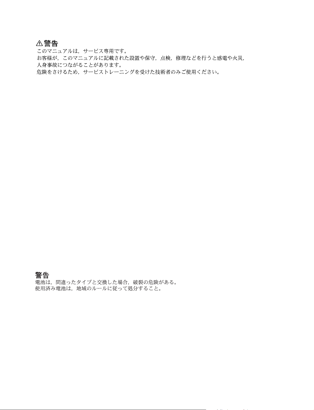
REMOTE COMMANDER
RM-PJHS50
SERVICE MANUAL
1st Edition
Page 2
! WARNING
This manual is intended for qualified service personnel only.
To reduce the risk of electric shock, fire or injury, do not perform any servicing other than that
contained in the operating instructions unless you are qualified to do so. Refer all servicing to
qualified service personnel.
! WARNUNG
Die Anleitung ist nur für qualifiziertes Fachpersonal bestimmt.
Alle Wartungsarbeiten dürfen nur von qualifiziertem Fachpersonal ausgeführt werden. Um die
Gefahr eines elektrischen Schlages, Feuergefahr und Verletzungen zu vermeiden, sind bei
War tungsarbeiten strikt die Angaben in der Anleitung zu befolgen. Andere als die angegeben
War tungsarbeiten dürfen nur von Personen ausgeführt werden, die eine spezielle Befähigung
dazu besitzen.
! AVERTISSEMENT
Ce manual est destiné uniquement aux personnes compétentes en charge de l’entretien. Afin
de réduire les risques de décharge électrique, d’incendie ou de blessure n’effectuer que les
réparations indiquées dans le mode d’emploi à moins d’être qualifié pour en effectuer d’autres.
Pour toute réparation faire appel à une personne compétente uniquement.
CAUTION
RISK OF EXPLOSION IF BATTERY IS REPLACED BY INCORRECT TYPE.
DISPOSE OF USED BATTERIES ACCORDING TO THE RULE IN REGION.
VPL-HS60/HS51A
Page 3

For the customers in the Netherlands
Voor de klanten in Nederland
Hoe u de batterijen moet verwijderen, leest u in de tekst
van deze handleiding.
Gooi de batterij niet weg maar lever deze in als klein
chemisch afval (KCA).
Für Kunden in Deutschland
Entsorgungshinweis: Bitte werfen Sie nur entladene
Batterien in die Sammelboxen beim Handel oder den
Kommunen. Entladen sind Batterien in der Regel dann,
wenn das Gerät abschaltet und signalisiert “Batterie
leer” oder nach längerer Gebrauchsdauer der Batterien
“nicht mehr einwandfrei funktioniert”. Um
sicherzugehen, kleben Sie die Batteriepole z.B. mit
einem Klebestreifen ab oder geben Sie die Batterien
einzeln in einen Plastikbeutel.
VPL-HS60/HS51A
1 (P)
Page 4

Page 5

Table of Contents
1. Service Overview
1-1. External View .............................................................................................. 1-1
1-2. Board Location ............................................................................................ 1-1
1-3. Removing/Installing the Cabinet................................................................. 1-2
1-3-1. Base Assembly ........................................................................... 1-2
1-3-2. Front Panel (D) Assembly/Front Panel (U) Assembly .............. 1-2
1-3-3. Rear Cover/Rear Panel ...............................................................1-3
1-4. Replacing the Board ....................................................................................1-4
1-4-1. C Board ...................................................................................... 1-4
1-4-2. GA Board ................................................................................... 1-6
1-4-3. GB Board ................................................................................... 1-7
1-4-4. U Board ...................................................................................... 1-7
1-4-5. V Board ...................................................................................... 1-8
1-4-6. Lamp Power Supply Board ........................................................ 1-8
1-4-7. F Board .......................................................................................1-9
1-4-8. HA Board/HB Board/L Board ................................................. 1-10
1-4-9. Q Board (VPL-HS51A) ............................................................ 1-11
1-5. Replacing the Main Parts .......................................................................... 1-11
1-5-1. DC Fan (for GA/GB unit) ........................................................ 1-11
1-5-2. Lamp Assembly ....................................................................... 1-12
1-5-3. Optical Block Assembly .......................................................... 1-12
1-5-4. DC Fan (for Lamp) ................................................................... 1-13
1-5-5. DC Fan (for Lamp Power Supply) and TA Board ................... 1-13
1-5-6. Prism Block and WV Plate (1), (2) .......................................... 1-14
1-5-7. Lens Unit ..................................................................................1-15
1-5-8. Unit Assembly .......................................................................... 1-16
1-5-9. Unit Assembly Parts Orientation ............................................. 1-17
1-5-10. Extension Board and Extension Connectors ............................1-18
1-5-11. Extension Board and Extension Connectors Connection ......... 1-19
1-6. Unleaded Solder ........................................................................................ 1-20
1-7. Service Knowhow ..................................................................................... 1-20
1-7-1. After Replacing the Prism Block ............................................. 1-20
1-7-2. After Replacing the Board ....................................................... 1-20
1-8. Memory .....................................................................................................1-22
1-9. Warning on Power Connection ................................................................. 1-24
VPL-HS60/HS51A
1
Page 6

2. Electrical Adjustments
2-1. Preparations ................................................................................................. 2-1
2-1-1. Required Equipment ................................................................... 2-1
2-1-2. Factory Mode Setting .................................................................2-1
2-2. V COM Adjustment .................................................................................... 2-1
2-3. Adjustment Item Initialize Data .................................................................. 2-2
2-4. White Balance Adjustment on Servicing .................................................. 2-16
2-4-1. Computer ..................................................................................2-16
2-4-2. Video ........................................................................................ 2-17
3. Semiconductors
4. Spare Parts
4-1. Notes on Repair Parts .................................................................................. 4-1
4-2. Exploded Views .......................................................................................... 4-2
4-3. Electrical Parts List ..................................................................................... 4-9
4-4. Packing Materials & Supplied Accessories .............................................. 4-31
5. Block Diagrams
Overall ......................................................................................................... 5-2
6. Schematic Diagrams
C .................................................................................................................. 6-2
F ................................................................................................................. 6-26
GA ............................................................................................................. 6-27
GB ............................................................................................................. 6-30
HA ............................................................................................................. 6-32
HB ............................................................................................................. 6-33
L ................................................................................................................ 6-34
NF .............................................................................................................. 6-34
TA ............................................................................................................. 6-34
U ................................................................................................................6-34
V ................................................................................................................6-34
Q (VPL-HS51A) ....................................................................................... 6-35
Frame Wiring ............................................................................................ 6-38
2
VPL-HS60/HS51A
Page 7

7. Board Layouts
C .................................................................................................................. 7-2
GA ...............................................................................................................7-4
GB ............................................................................................................... 7-5
F................................................................................................................... 7-6
HA ...............................................................................................................7-6
HB ............................................................................................................... 7-6
L .................................................................................................................. 7-6
NF ................................................................................................................ 7-6
Q (VPL-HS51A) ......................................................................................... 7-7
TA ............................................................................................................... 7-7
U ..................................................................................................................7-7
V ..................................................................................................................7-7
VPL-HS60/HS51A
3
Page 8

Page 9
1-1. External View
Section 1
Service Overview
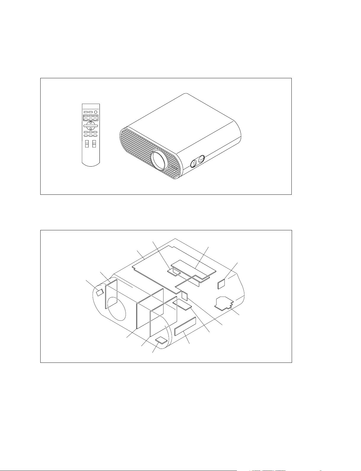
1-2. Board Location
Q board
(VPL-HS51A)
NF board
C board
GB board
GA board
TA board
Lamp power supply board
V board
F board
U board
L board
HB board
HA board
VPL-HS60/HS51A
1-1
Page 10
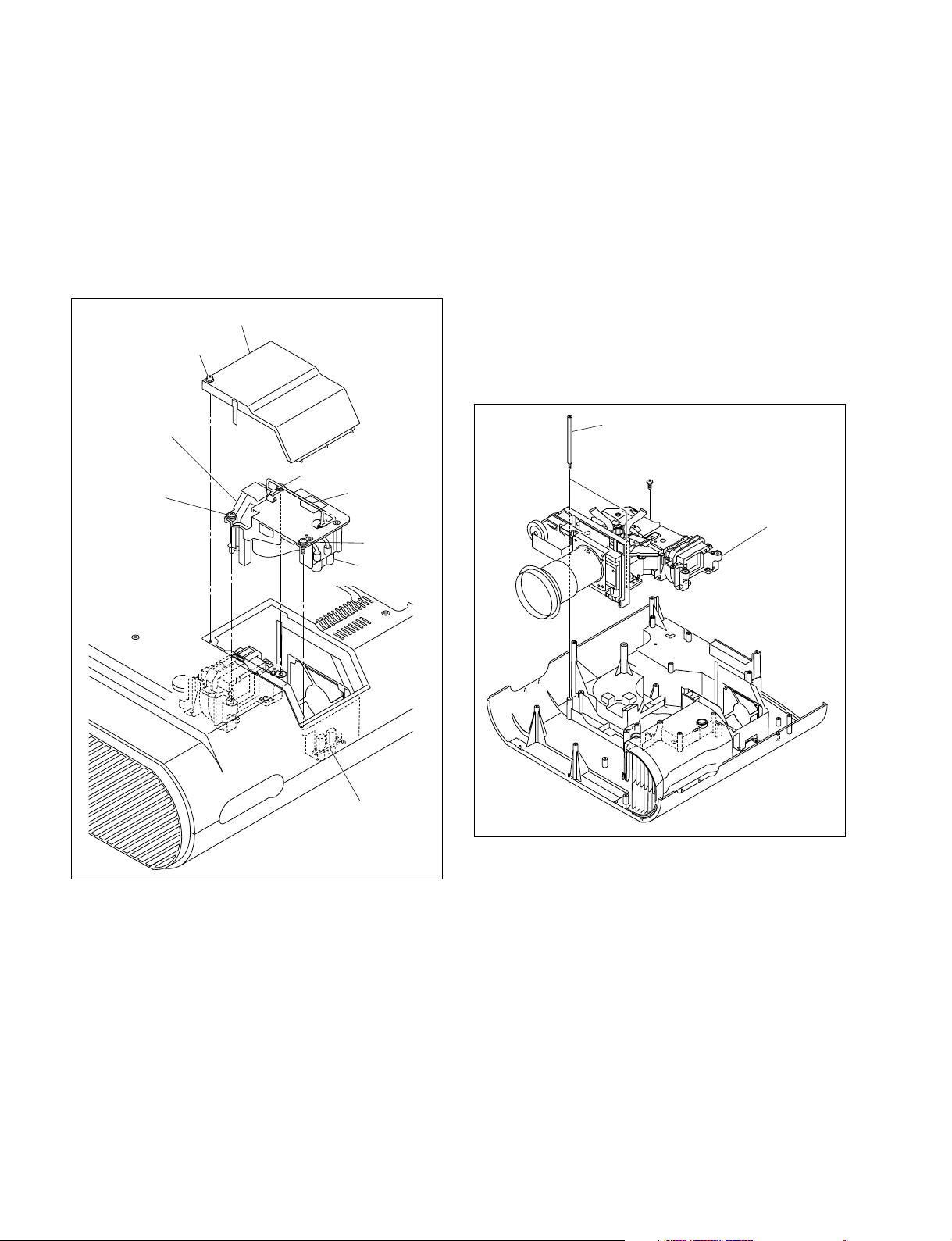
1-3. Removing/Installing the Cabinet
p p
y
n
When removing/installing or replacing the parts, place the
unit on the conductive cushion with the top panel assembly
down.
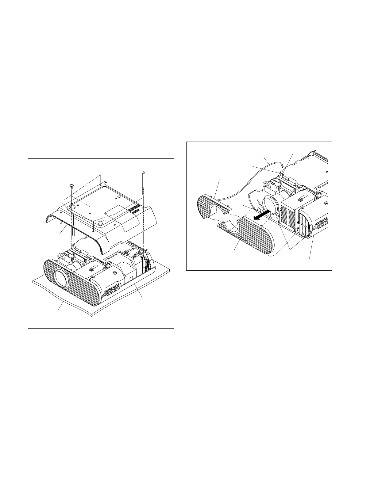
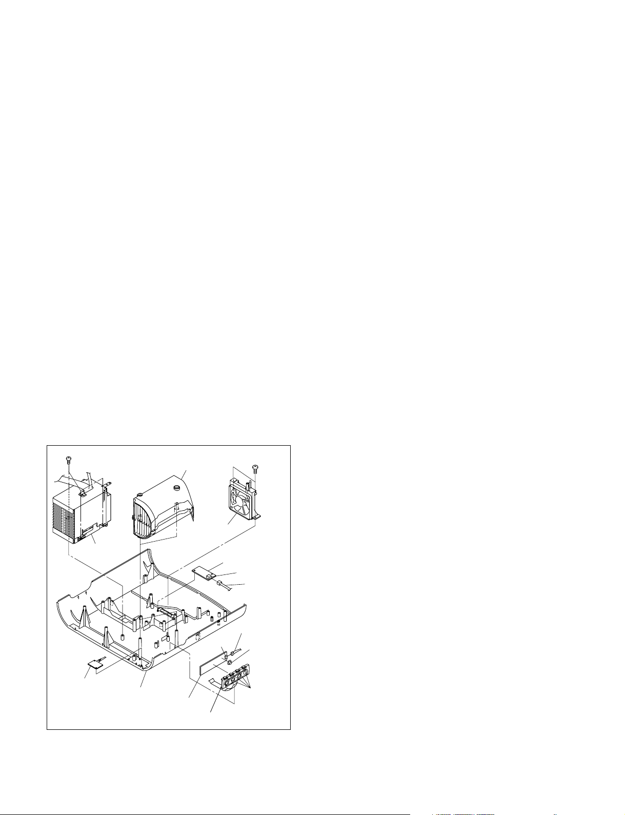
1-3-1. Base Assembly
Removal
1. Remove the six special screws (BV3 x 70) and two
screws (PSW3 x 8), then remove the base assembly.
BV3 x 70
PSW3 x 8
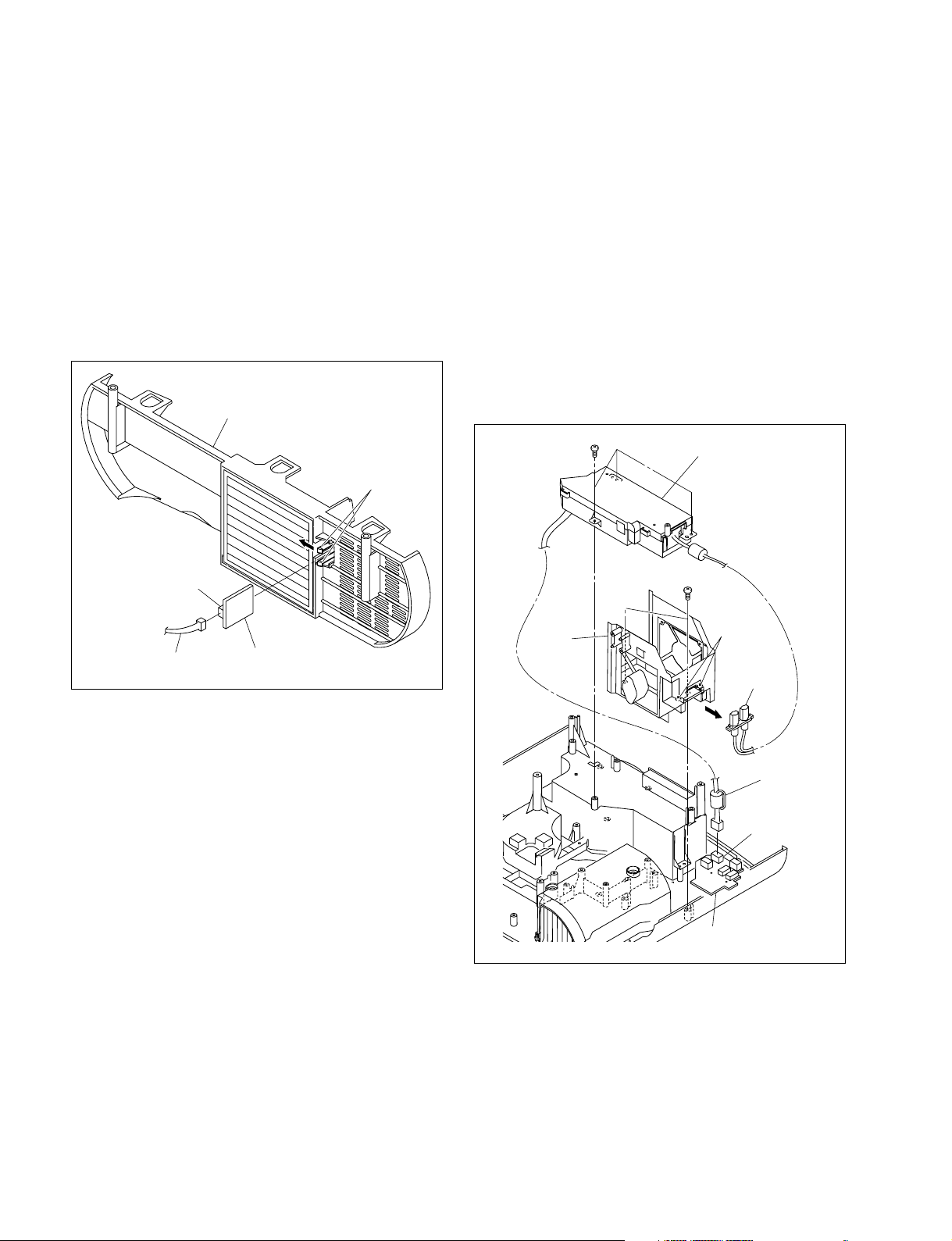
1-3-2. Front Panel (D) Assembly/Front Panel
(U) Assembly
Removal (VPL-HS60)
1. Remove the base assembly. (Refer to Section 1-3-1.)
2. Disconnect the harness from the connector (CN1903)
on the C board, then remove the front panel (D).
3. Remove the front panel (U) assembly from the three
projections of the top panel assembly in the direction
shown by the arrow.
Harness
C board
Front panel (D) assembly
Projection
CN1903
Base assembly
Conductive cushion
Installation
2. Attach the base assembly.
Top panel assembly
Front panel (U) assembly
Projections
anel assembl
To
Installation (VPL-HS60)
4. Attach the front panel (D) assembly and front panel
(U) assembly in the reverse order of steps 2 and 3.
5. Attach the base assembly.
1-2
VPL-HS60/HS51A
Page 11
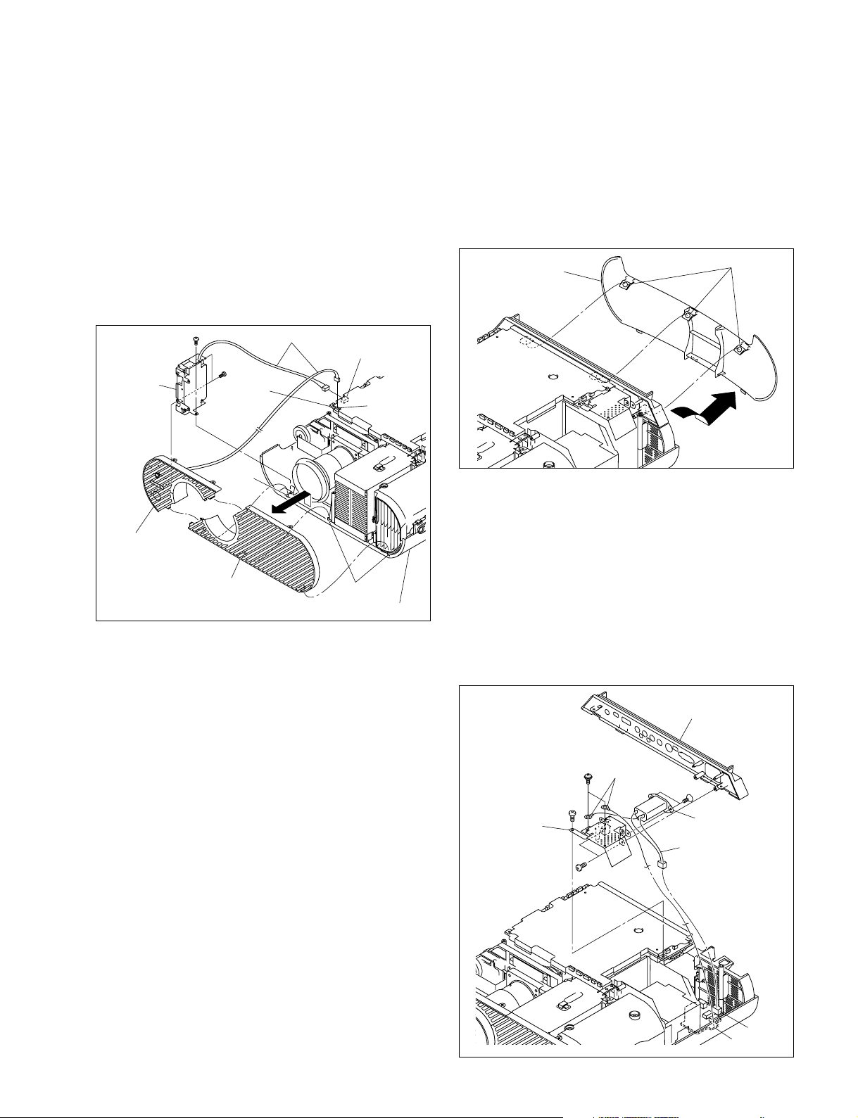
Removal (VPL-HS51A)
Por tions A
Rear cover
F board
CN11
AC inlet
Bracket
(AC)
Connector panel
assembly
PSW
4 x 8
K3 x 6
BTP
3 x 12
BTP
3 x 12
Harness
Harnesses
(GND)
1. Remove the base assembly. (Refer to Section 1-3-1.)
2. Remove the screw and disconnect the two harnesses
from the connector (CN1806, 1903) on the C board,
then remove the front panel (D).
3. Remove the two screws, them remove the Q board
assembly.
4. Remove the front panel (U) assembly from the three
projections of the top panel assembly in the direction
shown by the arrow.
1-3-3. Rear Cover/Rear Panel
Removal
1. Remove the base assembly. (Refer to Section 1-3-1.)
2. Push the three portions A of the rear cover, then remove
the rear cover in the direction shown by the arrow.
BTP
3 x 12
Q board
assembly
Front panel (D)
assembly
BTP
3 x 12
Projection
Front panel (U)
assembly
Harnesses
CN1806
C board
CN1903
Projections
Top panel assembly
Installation (VPL-HS51A)
5. Attach the front panel (D) assembly and front panel
(U) assembly in the reverse order of steps 2 to 4.
6. Attach the base assembly.
3. Remove the screw (BTP3 x 12), then remove the
connector panel assembly.
4. Disconnect the harness from the connector (CN11) on
the F board.
5. Remove the two screws (BTP3 x 12), then remove the
bracket (AC).
6. Remove the two screws (PSW4 x 8), then disconnect
the two harnesses (GND) from the bracket (AC).
7. Remove the two screws (K3 x 6), then remove the AC
inlet.
VPL-HS60/HS51A
1-3
Page 12
8. Disconnect the harness from the connector (CN201)
on the C board.
9. Remove the filter assembly.
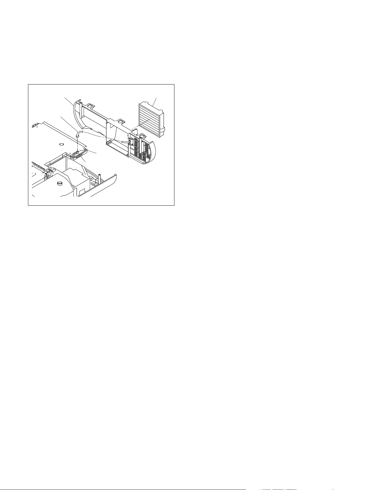
10. Remove the rear panel.
Rear panel Filter assembly
Harness
C board
CN201
Installation
11. Attach the rear cover and the rear panel in the reverse
order of steps 2 to 10.
1-4. Replacing the Board
1-4-1. C Board
Removal
1. Remove the base assembly. (Refer to Section 1-3-1.)
2. Remove the rear cover and connector panel assembly.
(Refer to steps 2 to 4 of Section 1-3-3.)
3. Remove the four screws and disconnect the harness
from the connector (CN14) on the F board.
4. Remove the shield plate (CU).
5. Disconnect all harnesses and flexible flat cables from
the connectors on the C board, then remove the C
board.
6. Remove the shield plate (CD) from the C board.
12. Attach the base assembly.
1-4
VPL-HS60/HS51A
Page 13
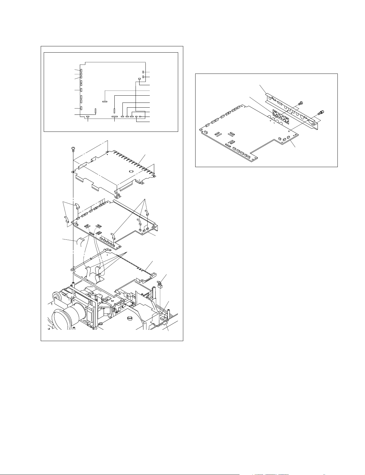
CN1907
CN1906
CN1911
CN2000
CN1806
(VPL-HS51)
CN1500
Harnesses
BTP
3 x 12
CN1903
C board (Side A)
CN1900
Shield plate (CU)
CN201
CN1905
CN1910
CN1600
CN1700
CN1909
CN1901
CN1902
CN203
CN1903
Harnesses
7. Remove the two screws and two connector screws,
then remove the shield plate (connector) and plate
(connector).
Shield plate (connector)
Plate (connector)
BTP
3 x 12
C board
Connector
screws
Installation
8. Install the C board in the reverse order of steps 3 to 7.
9. Assemble this unit in the reverse order of steps 1 and 2.
Flexible flat
cable
C board
Flexible flat cables
Shield plate (CD)
Harness
CN14
F board
VPL-HS60/HS51A
1-5
Page 14
1-4-2. GA Board
Removal
1. Remove the cabinet. (Refer to Section 1-3.)
2. Remove the C board.
(Refer to steps 3 to 7 of Section 1-4-1.)
3. Remove the lamp assembly.
(Refer to steps 2 and 3 of Section 1-5-2.)
4. Remove the optical block assembly.
(Refer to step 5 of Section 1-5-3.)
5. Remove the lamp house.
(Refer to step 5 of Section 1-4-6.)
6. Remove the GA/GB unit.
(Refer to step 7 of Section 1-4-8.)
7. Remove the shield plate (GD) in the direction shown
by the arrow.
8. Remove the two screws, then remove the shield plate
(GU).
BTP3 x 12
Shield plate (GU)
9. Remove the three hooks, then remove the holder (GB)
from the holder (GA).
10. Disconnect the harness from the connector (CN300)
on the GA board.
11. Remove the screw and disconnect the harness from the
connector (CN101) on the GA board.
Holder (GB)
Hooks
Harness
CN101
Hook
Harness
CN300
GA board
Holder (GA)
BTP3 x 12
BTP3 x 12
Installation
12. Install the GA board in the reverse order of steps 7 to
11.
n
When attaching the holder (GA) and holder (GB), be
careful not to catch the harness and flexible flat cable.
13. Assemble this unit in the reverse order of steps 1 to 6.
1-6
Shield plate (GD)
VPL-HS60/HS51A
Page 15
(G)
1-4-3. GB Board
1-4-4. U Board
Removal
1. Remove the cabinet. (Refer to Section 1-3.)
2. Remove the C board.
(Refer to steps 3 to 7 of Section 1-4-1.)
3. Remove the lamp assembly.
(Refer to steps 2 and 3 of Section 1-5-2.)
4. Remove the optical block assembly.
(Refer to step 5 of Section 1-5-3.)
5. Remove the lamp house.
(Refer to step 5 of Section 1-4-6.)
6. Remove the GA/GB unit.
(Refer to step 7 of Section 1-4-8.)
7. Remove the holder (GA) and holder (GB).
(Refer to steps 7 to 10 of Section 1-4-2.)
8. Remove the screw, then remove the GB board.
9. Remove the sheet (G) from the GB board in the
direction shown by the arrow.
10. Disconnect the harness from the connector (CN350)
on the GB board.
11. Disconnect the flexible flat cable from the connector
(CN400) on the GB board.
BTP
3 x 12
GB board
Removal
1. Remove the base assembly. (Refer to Section 1-3-1.)
2. Remove the front panel (D) assembly and front panel
(U) assembly.
(Refer to steps 2 and 3 of Removal (VPL-HS60) in
Section 1-3-2.)
(Refer to steps 2 to 4 of Removal (VPL-HS51A) in
Section 1-3-2.)
3. Remove the two screws and disconnect the harness
from the connector (CN203) on the C board, then
remove the U board.
4. Disconnect the harness from the connector (CN20) on
the U board.
BTP
3 x 12
CN203
U board
CN20
Harness
C board
Flexible flat cable
CN400
Holder (GB)
CN350
Harness
Sheet
Installation
12. Install the GB board in the reverse order of steps 8 to
11.
n
When attaching the holder (GA) and holder (GB), be
careful not to catch the harness and flexible flat cable.
13. Assemble this unit in the reverse order of steps 1 to 7.
Installation
5. Install the U board in the reverse order of steps 3 and
4.
6. Assemble this unit in the reverse order of steps 1 and
2.
VPL-HS60/HS51A
1-7
Page 16
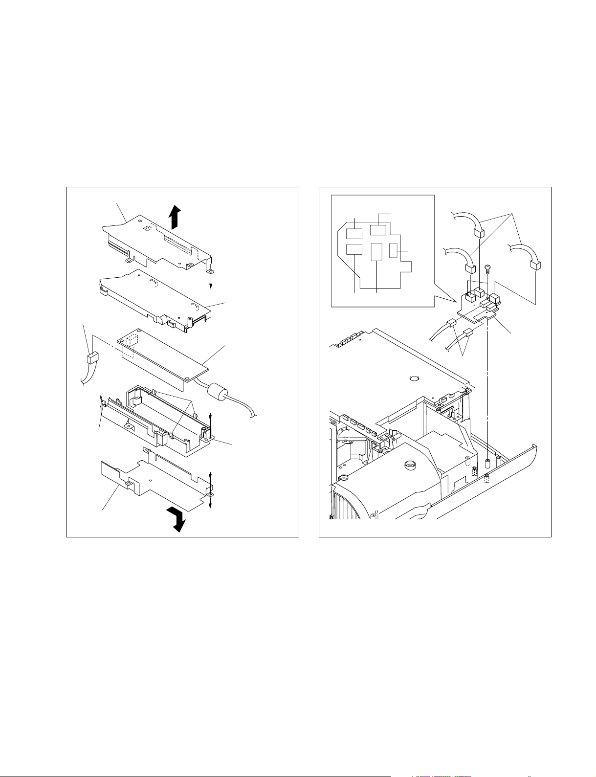
1-4-5. V Board
1-4-6. Lamp Power Supply Board
Removal
1. Remove the base assembly. (Refer to Section 1-3-1.)
2. Remove the rear cover and rear panel.
(Refer to Section 1-3-3.)
3. Remove the two hooks of the rear panel, then remove
the V board.
4. Disconnect the harness from the connector (CN30) on
the V board.
Rear panel
Hooks
CN30
Removal
1. Remove the cabinet. (Refer to Section 1-3.)
2. Remove the C board.
(Refer to steps 3 to 6 of Section 1-4-1.)
3. Remove the lamp assembly.
(Refer to steps 2 and 3 of Section 1-5-2.)
4. Remove the three screws and disconnect the harness
from the connector (CN14) on the F board, then
remove the lamp power supply unit.
5. Remove the two screws, then remove the lamp house.
6. Loosen the two screws, then remove the connector.
BTP
3 x 12
Lamp power supply unit
BTP
3 x 12
Harness
V board
Installation
5. Install the V board in the reverse order of steps 3 and
4.
6. Assemble this unit in the reverse order of steps 1 and
2.
Lamp
house
Screws
Connector
Harness
CN14
F board
1-8
VPL-HS60/HS51A
Page 17
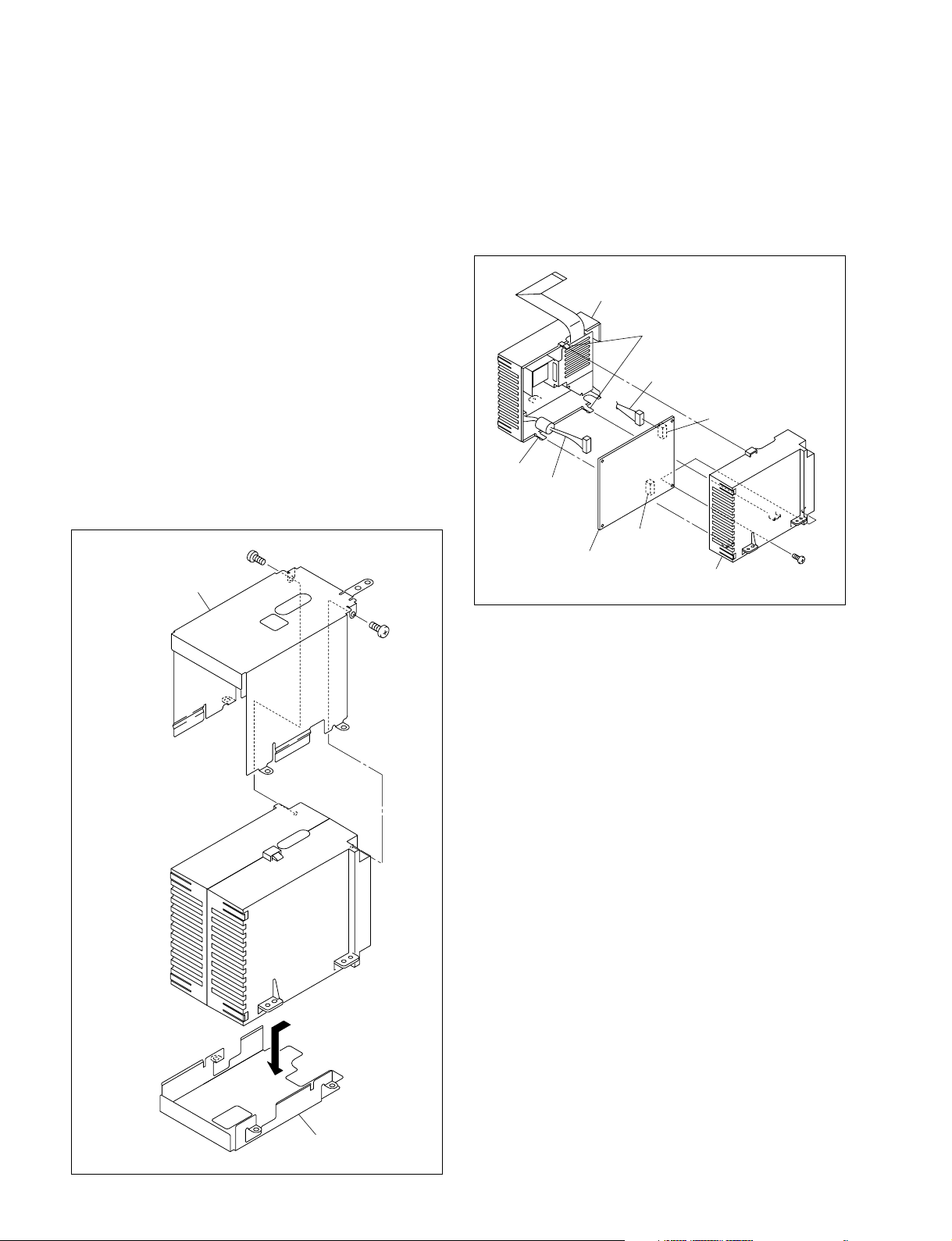
7. Remove the shield plate (BD) in the direction shown
BTP
3 x 12
CN13
CN12
CN11CN14
CN10
F board (Side A)
F board
Harnesses
Harnesses
by the arrow.
8. Remove the shield plate (BU) in the direction shown
by the arrow.
9. Remove the four hooks of the holder (BD), then
remove the holder (BU) and lamp power supply board.
10. Disconnect the harness from the connector on the lamp
power supply board.
Shield plate (BU)
A
Holder (BU)
Harness
Lamp power supply
board
1-4-7. F Board
Removal
1. Remove the cabinet. (Refer to Section 1-3.)
2. Disconnect the five harnesses from the connector
(CN10 to CN14) on the F board.
3. Remove the two screws, then remove the F board.
Hooks
B
Hook
Holder (BD)
Shield plate (BD)
A
B
Installation
11. Install the lamp power supply board in the reverse
order of steps 5 to 10.
12. Assemble this unit in the reverse order of steps 1 to 4.
Installation
4. Install the F board in the reverse order of steps 2 and 3.
5. Attach the cabinet.
VPL-HS60/HS51A
1-9
Page 18
1-4-8. HA Board/HB Board/L Board
(H)
Removal
1. Remove the cabinet. (Refer to Section 1-3.)
2. Remove the C board.
(Refer to steps 3 to 7 of Section 1-4-1.)
3. Remove the lamp assembly.
(Refer to steps 2 and 3 of Section 1-5-2.)
4. Remove the optical block assembly.
(Refer to step 5 of Section 1-5-3.)
5. Remove the lamp house.
(Refer to step 5 of Section 1-4-6.)
6. Remove the duct lamp assembly.
7. Remove the three screws, then remove the GA/GB unit.
8. Remove the two screws, then remove the fan holder (G).
9. Remove the HA board.
10. Remove the escutcheon (H) from the top panel
assembly.
11. Remove the four hooks, then remove the HB board.
12. Disconnect the harness from the connector (CN80) on
the HB board.
13. Remove the button (P) from the HB board.
14. Remove the L board.
15. Disconnect the harness from the connector (CN001)
on the L board.
Installation
16. Install the HA board, HB board and L board in the
reverse order of steps 6 to 15.
17. Assemble this unit in the reverse order of steps 1 to 5.
BTP
3 x 12 (BLK)
GA/GB unit
HA board
Duct lamp assembly
Top panel assembly
HB board
Fan holder (G)
L board
CN80
Escutcheon
BTP
3 x 12
CN001
Harness
Harness
Button (P)
Hooks
1-10
VPL-HS60/HS51A
Page 19
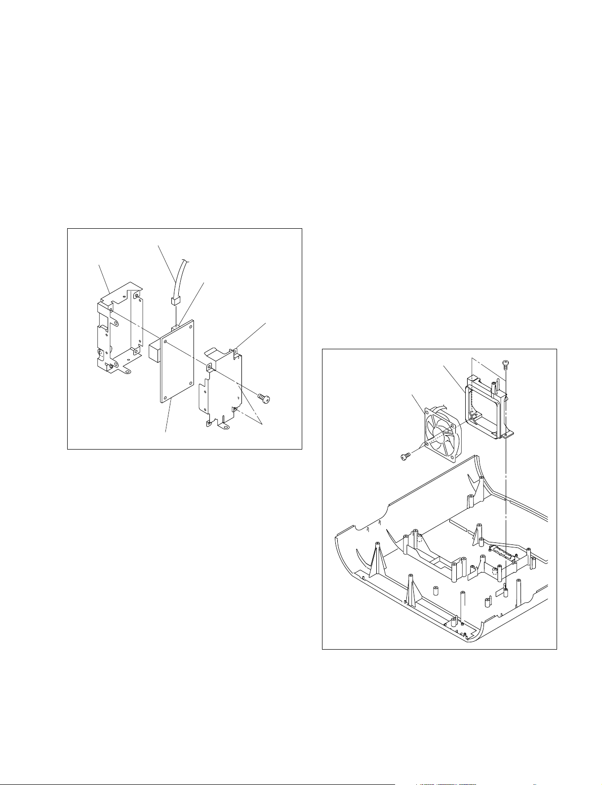
1-4-9. Q Board (VPL-HS51A)
1-5. Replacing the Main Parts
Removal
1. Remove the base assembly. (Refer to Section 1-3-1.)
2. Remove the front panel (D) assembly.
(Refer to steps 2 to 4 of Removal (VPL-HS51A) in
Section 1-3-2.)
3. Remove the two screws, then remove the Q board.
4. Disconnect the harness from the connector (CN5002)
on the Q board.
Harness
Shield plate
(ED)
CN5002
Shield plate (EU)
PSW
3 x 8
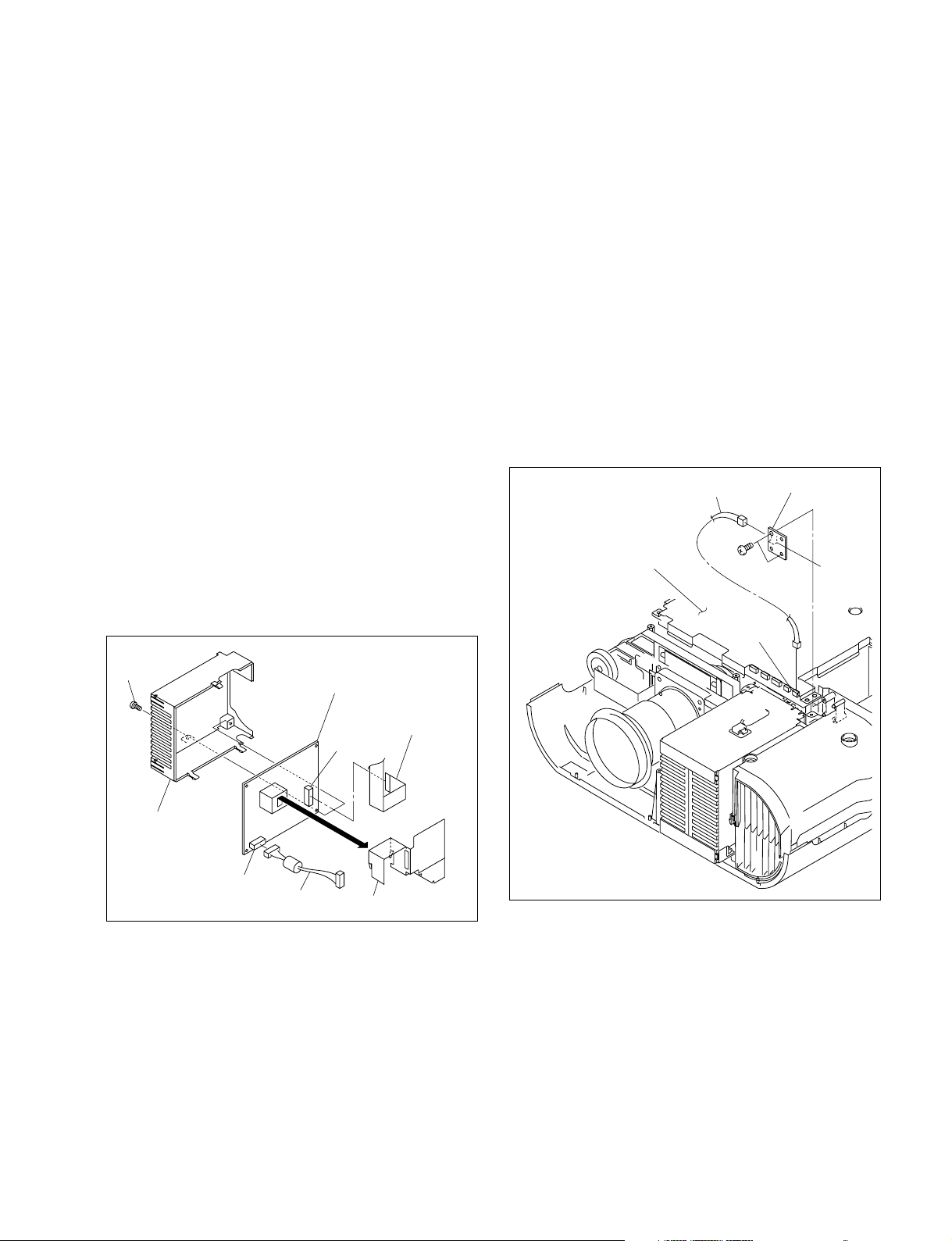
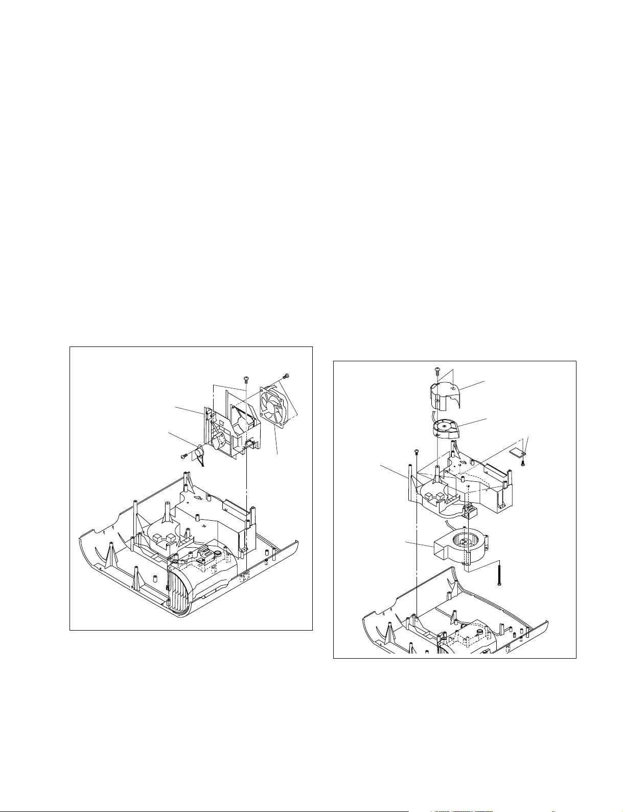
1-5-1. DC Fan (for GA/GB unit)
Removal
1. Remove the cabinet. (Refer to Section 1-3.)
2. Remove the C board.
(Refer to steps 3 to 7 of Section 1-4-1.)
3. Remove the lamp assembly.
(Refer to steps 2 and 3 of Section 1-5-2.)
4. Remove the optical block assembly.
(Refer to step 5 of Section 1-5-3.)
5. Remove the lamp house.
(Refer to step 5 of Section 1-4-6.)
6. Remove the duct lamp assembly.
(Refer to step 6 of Section 1-4-8.)
7. Remove the two screws, then remove the fan holder (G).
8. Remove the two screws, then remove the DC fan (for
GA/GB unit).
Fan holder (G)
DC fan
(for GA/GB unit)
BTP
3 x 12
Q board
Installation
5. Install the Q board in the reverse order of steps 3, 4.
6. Assemble this unit in the reverse order of steps 1 and 2.
BTP
3 x 12
Installation
9. Attach the DC fan (for GA/GB unit) in the reverse
order of steps 7 and 8.
VPL-HS60/HS51A
10. Assemble this unit in the reverse order of steps 1 to 6.
1-11
Page 20
1-5-2. Lamp Assembly
1-5-3. Optical Block Assembly
Removal
1. Loosen the screw [A], then remove the lamp cover
assembly.
2. Loosen the three screws [B].
3. Hold the lamp handle, then lift the lamp assembly
slowly.
Lamp cover assembly
Screw [A]
Lamp assembly
Screw [B]
Screw [B]
Lamp handle
Screw [B]
Connector
[A]
Removal
1. Remove the cabinet. (Refer to Section 1-3.)
2. Remove the C board.
(Refer to steps 3 to 6 of Section 1-4-1.)
3. Remove the lamp assembly.
(Refer to steps 2 and 3 of Section 1-5-2.)
4. Remove the lamp power supply board.
(Refer to steps 4 to 10 of Section 1-4-6.)
5. Remove the screw and two spacers, then remove the
optical block assembly.
Spacer
BTP
3 x 12
Optical block
assembly
Connector [B] of
lamp house
Installation
4. Attach the lamp assembly in the reverse order of steps
1 to 3.
n
When attaching the lamp assembly, be sure to securely
insert the connector [A] of the lamp assembly into the
connector [B] of the lamp house.
1-12
Installation
6. Attach the optical block assembly in the reverse order
of step 5.
7. Assemble this unit in the reverse order of steps 1 to 4.
VPL-HS60/HS51A
Page 21
1-5-4. DC Fan (for Lamp)
1-5-5. DC Fan and TA Board
Removal
1. Remove the cabinet. (Refer to Section 1-3.)
2. Remove the C board.
(Refer to steps 3 to 6 of Section 1-4-1.)
3. Remove the lamp assembly.
(Refer to steps 2 and 3 of Section 1-5-2.)
4. Remove the lamp power supply unit.
(Refer to step 4 of Section 1-4-6.)
5. Remove the optical block assembly.
(Refer to step 5 of Section 1-5-3.)
6. Remove the two screws (BTP3 x 12), then remove the
lamp house.
7. Remove the two screws (BTP3 x 12), then remove the
DC fan (for lamp).
8. Remove the two screws (BVTP3 x 6), then remove
the thermostat.
BTP
3 x 12
DC fan
(for lamp)
Lamp house
Thermostat
BVTP
3 x 8
BTP
3 x 12
Removal
1. Remove the cabinet. (Refer to Section 1-3.)
2. Remove the C board.
(Refer to steps 3 to 7 of Section 1-4-1.)
3. Remove the lamp assembly.
(Refer to steps 2 and 3 of Section 1-5-2.)
4. Remove the lamp power supply board.
(Refer to step 4 to 10 of Section 1-4-6.)
5. Remove the optical block assembly.
(Refer to step 5 of Section 1-5-3.)
6. Remove the two screws (BVTP3 x 20), then remove
the fan cover (B) and DC fan (Sirocco) [A].
7. Remove the five screws (BTP3 x 12), then remove the
duct (panel).
8. Remove the two screws (PTP4 x 45), then remove the
DC fan (sirocco) [B].
9. Remove the screw (BTP3 x 12), then remove the TA board.
BVTP3 x 20
Fan cover (B)
DC fan (sirocco) [A]
TA board
BTP
3 x 12
Duct
(panel)
BTP
3 x 12
Installation
9. Attach the DC fan (for lamp) in the reverse order of
steps 5 to 7.
10. Assemble this unit in the reverse order of steps 1 to 4.
VPL-HS60/HS51A
DC fan
(sirocco)
[B]
PTP4 x 45
Installation
10. Attach the DC fan and TA board in the reverse order
of steps 6 to 9.
11. Assemble this unit in the reverse order of steps 1 to 5.
1-13
Page 22
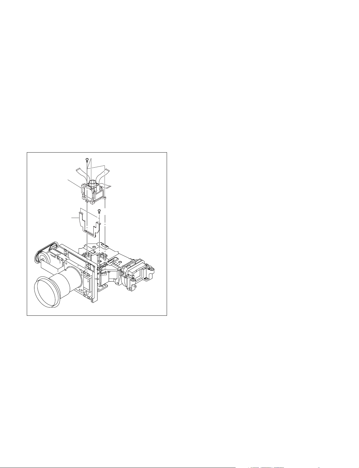
1-5-6. Prism Block
Removal
1. Remove the cabinet. (Refer to Section 1-3.)
2. Remove the C board.
(Refer to steps 3 to 7 of Section 1-4-1.)
3. Remove the lamp assembly.
(Refer to steps 2 and 3 of Section 1-5-2.)
4. Remove the optical block assembly.
(Refer to step 5 of Section 1-5-3.)
5. Remove the two screws (PWH M2 x 5) and three
screws (B2 x 8), then remove the prism block.
B2 x 8
Prism block
PWH M2 x 5
Shade Plate(LCD)
Installation
6. Assemble this unit in the reverse order of steps 1 to 5.
1-14
VPL-HS60/HS51A
Page 23
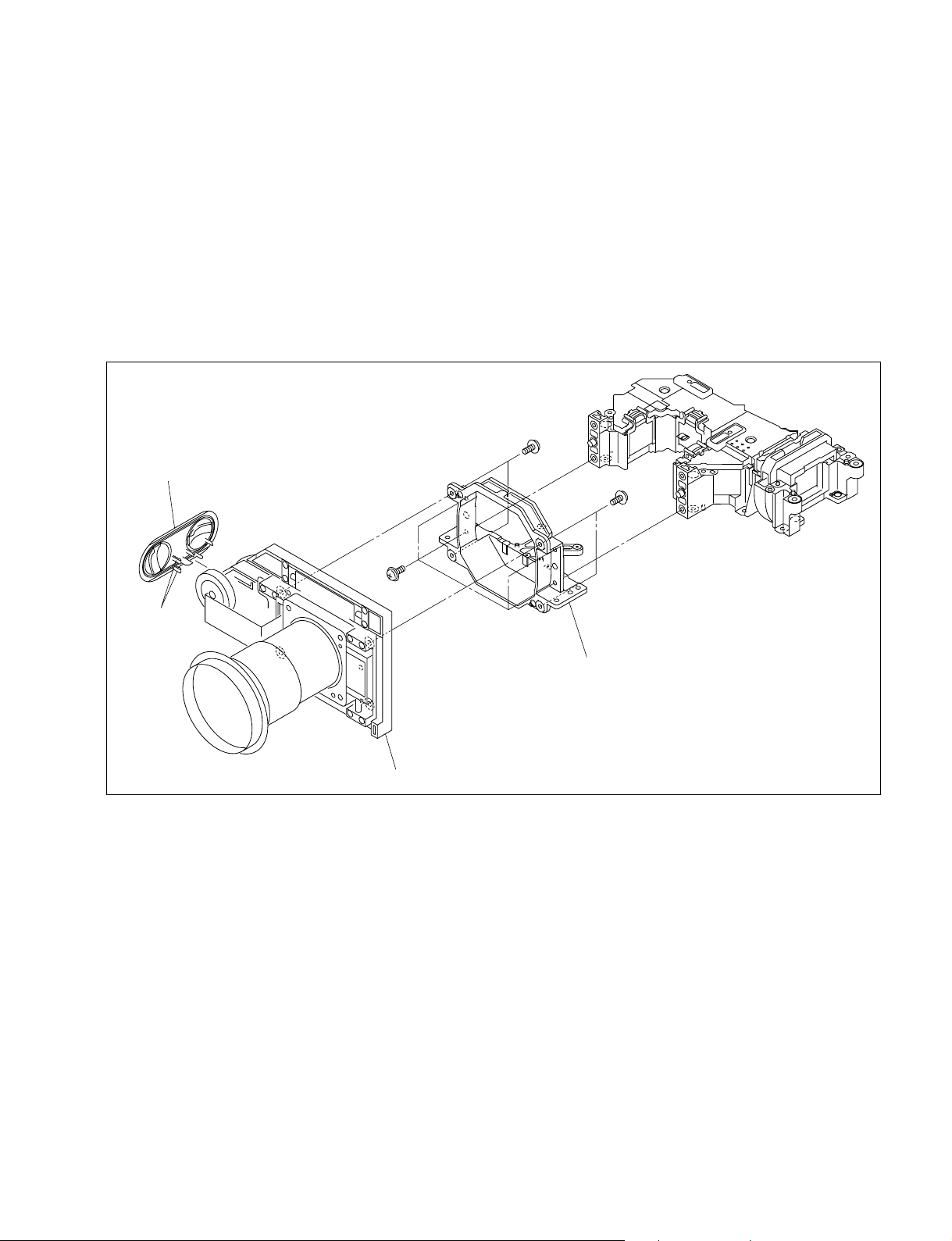
1-5-7. Lens Unit
M3 x 10
M3 x 10
M3 x 10
Escutcheon (S)
Lens unit
Lens holder
Hooks
Removal
1. Remove the cabinet. (Refer to Section 1-3.)
2. Remove the C board. (Refer to steps 3 to 7 of Section 1-4-1.)
3. Remove the lamp assembly. (Refer to steps 2 and 3 of Section 1-5-2.)
4. Remove the optical block assembly. (Refer to step 5 of Section 1-5-3.)
5. Remove the four screws, then remove the lens holder from the lens unit.
6. Remove the four screws, then remove the lens unit.
7. Remove the two hooks, then remove the escutcheon (S).
Installation
8. Attach the lens unit in the reverse order of steps 5 to 7.
9. Assemble this unit in the reverse order of steps 1 to 4.
VPL-HS60/HS51A
1-15
Page 24
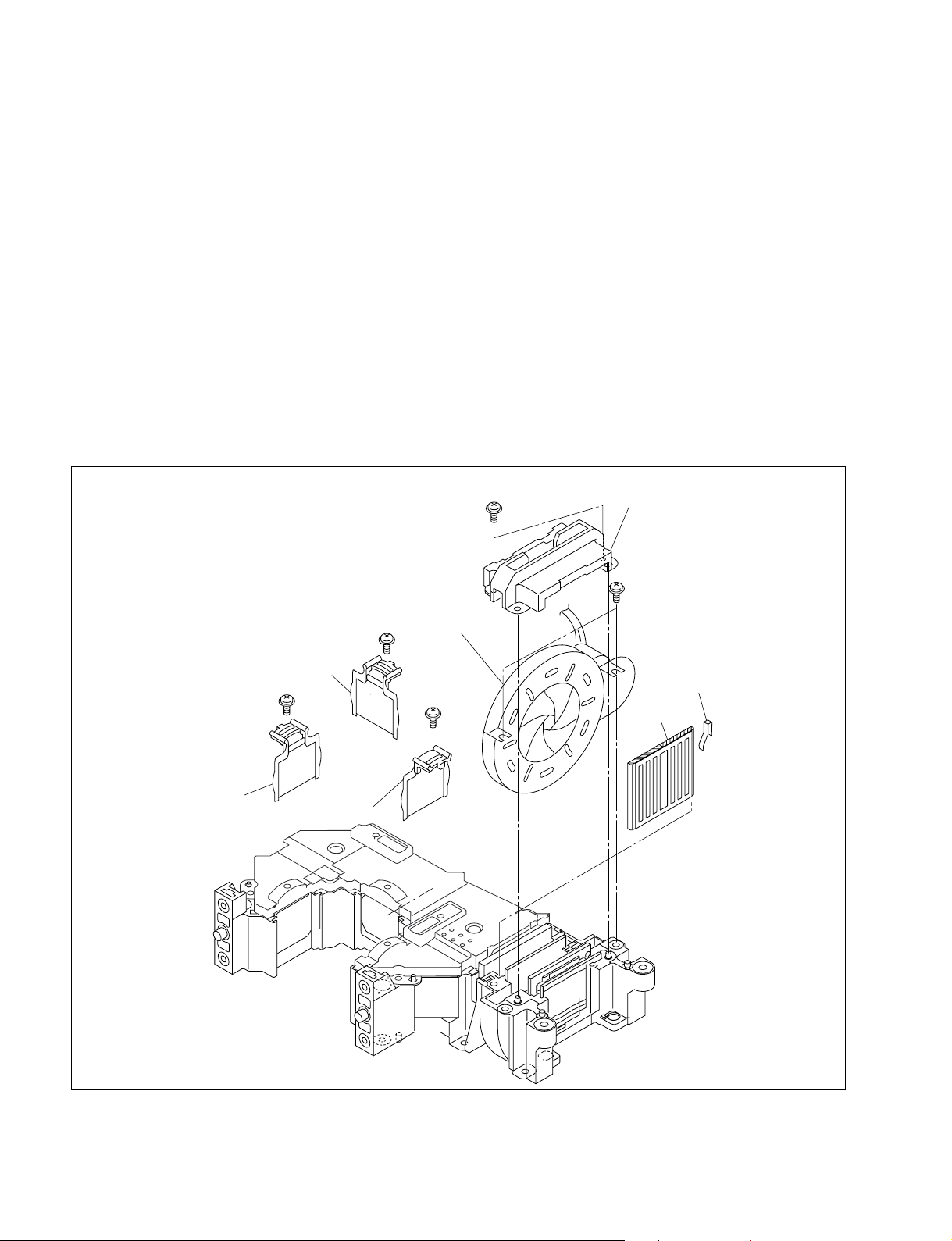
1-5-8. Unit Assembly
Removal
1. Remove the cabinet. (Refer to Section 1-3.)
2. Remove the C board.
(Refer to steps 3 to 7 of Section 1-4-1.)
3. Remove the lamp assembly.
(Refer to steps 2 and 3 of Section 1-5-2.)
4. Remove the optical block assembly.
(Refer to step 5 of Section 1-5-3.)
5. Remove the prism block.
(Refer to step 5 of Section 1-5-6.)
6. Remove the screw (PWH M2 x 5), then remove the
in-polarizer plate (R) assembly on the incoming
radiation side.
7. Remove the screw (PWH M2 x 5), then remove the
in-polarizer plate (G) assembly on the incoming
radiation side.
8. Remove the screw (PWH M2 x 5), then remove the
in-polarizer plate (B) assembly on the incoming
radiation side.
9. Remove the two screws (PWH M2 x 5) from the iris
unit.
10. Remove the two screws (PWH M2 x 5), then remove
the unit cover (BF).
11. Remove the iris unit.
12. Remove the spring (FE), then remove the P/S
conversion device.
PWH
M2 x 5
Unit cover (BF)
PWH
M2 x 5
In-polarizer plate (G)
assembly
PWH
M2 x 5
In-polarizer
plate (R)
assembly
PWH
M2 x 5
In-polarizer
plate (B)
assembly
Iris unit
PWH
M2 x 5
Spring (FE)
P/S converter
Installation
13. Attach the unit assembly in the reverse order of steps 6
to 12.
1-16
14. Assemble this unit in the reverse order of steps 1 to 5.
VPL-HS60/HS51A
Page 25
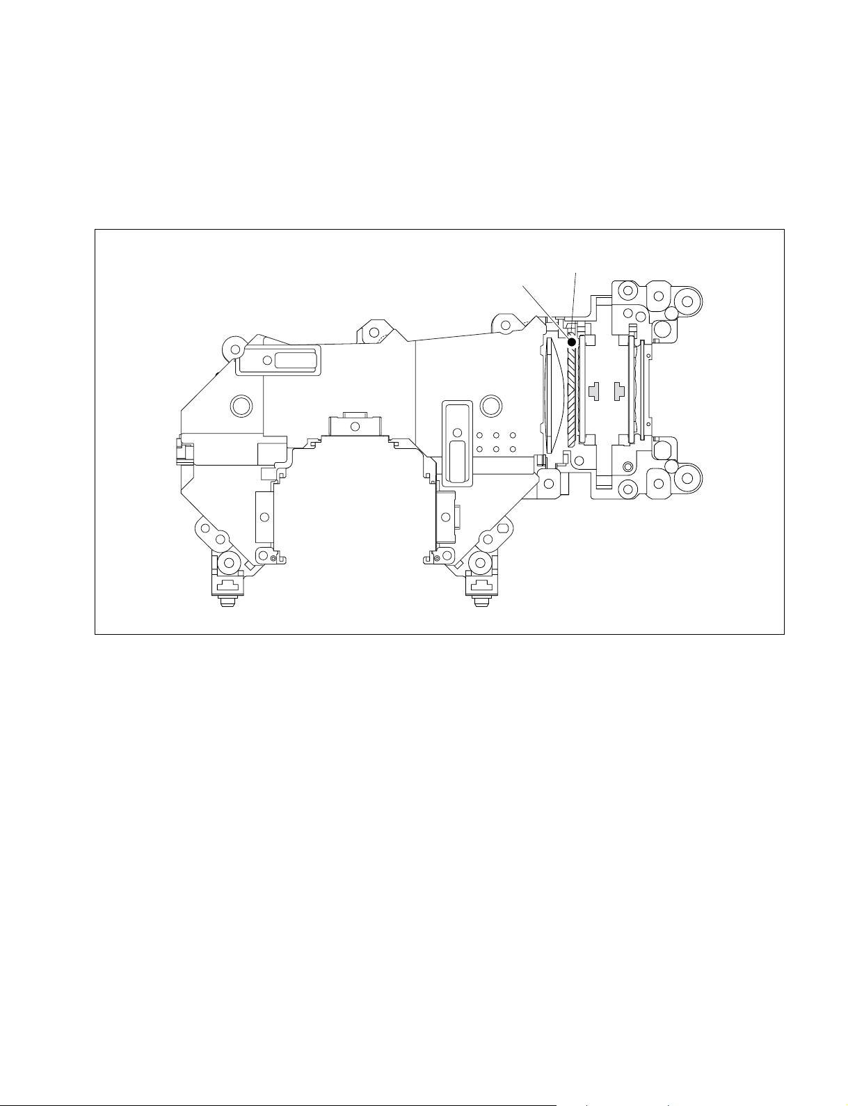
1-5-9. Unit Assembly Parts Orientation
n
The main condenser lens assembly and the relay-2 lens assembly are fixed to the unit assembly and
cannot be removed.
PS converter
marking
VPL-HS60/HS51A
1-17
Page 26
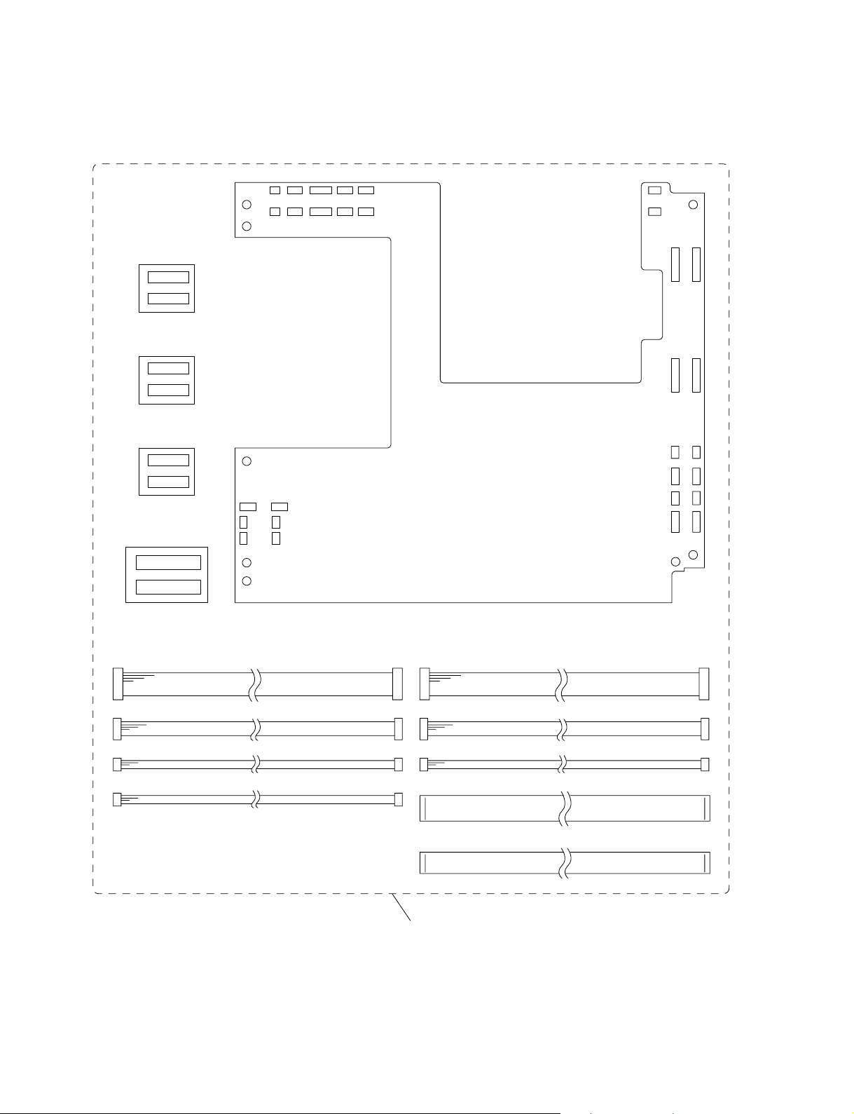
1-5-10. Extension Board and Extension Connectors
X2 BOARD
X2 BOARD
X2 BOARD
X1 BOARD
X3 BOARD
SH connector assembly (8P) 2 pcs
SH connector assembly (4P) 3 pcs
SH connector assembly (3P) 2 pcs
SH connector assembly (2P) 3 pcs
ZH connector assembly (8P) 1 pc
ZH connector assembly (4P) 1 pc
ZH connector assembly (3P) 3 pcs
Flat connector assembly (32P) 3 pcs
Flat connector assembly (24P) 1 pcs
X kit assembly (A-1097-951-A)
1-18
VPL-HS60/HS51A
Page 27
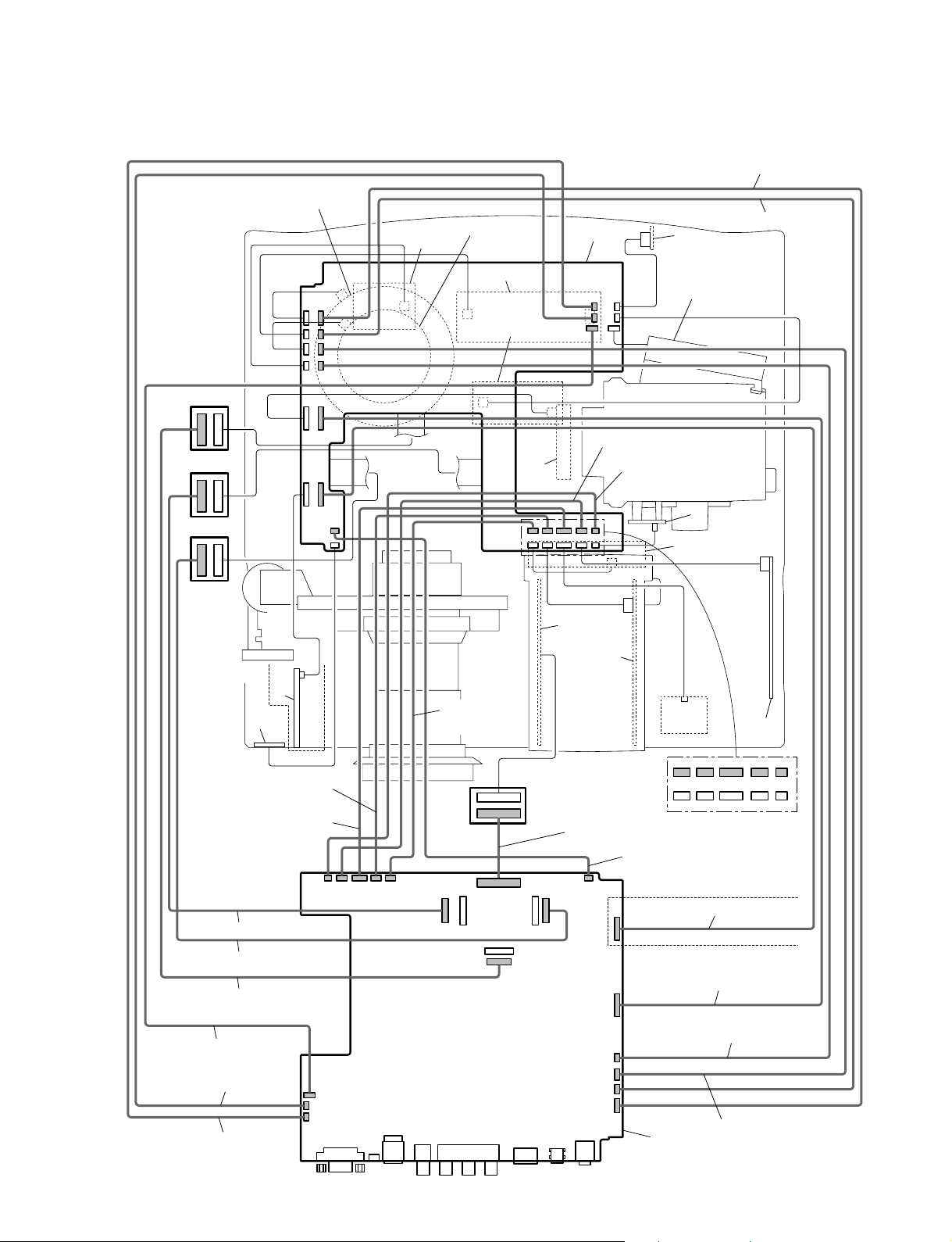
1-5-11. Extension Board and Extension Connectors Connection
DC fan (panel)
CN6907
CN6906
CN6911
CN6902
CN1907
CN1906
CN1911
CN1902
DC fan (ballast)
TA
Lamp power
CN50
L
CN201
CN1905
CN1910
X1
CN30
CN5201
CN6905
CN6910
ZH connector assembly (4P)
SH connector assembly (4P)
V
DC fan (LAMP)
X2
CN7000
CN2000
X2
CN6806
CN1806
X2
(VPL-HS51)
Q
CN1903
CN6903
CN5002
NF
CN40
SH connector assembly (4P)
SH connector assembly (8P)
CN001
ZH connector
assembly (3P)
X3
IRIS
SH connector assembly (3P)
SH connector assembly (2P)
CN20
U
DC fan (POWER)
GB
CN101
GA
HA
CN80
Flat connector assembly (24P)
SH connector assembly (4P)
CN60
HB
CN203CN1093CN1092CN1901CN1909
CN5203CN6093CN6092CN6901CN6909
Flat connector assembly (32P)
Flat connector assembly (32P)
Flat connector assembly (32P)
ZH connector assembly (3P)
SH connector assembly (3P)
SH connector assembly (2P)
VPL-HS60/HS51A
CN203
CN1910
CN1905
CN201
CN1903
CN1901
CN1909CN1902
CN1700
CN1600
CN1500
CN1903
(VPL-HS51A)
SH connector assembly (8P)
CN1806
ZH connector assembly (8P)
CN2000
SH connector assembly (2P)
CN1902
CN1911
CN1906
CN1907
C
ZH connector assembly (3P)
1-19
Page 28

1-6. Unleaded Solder
3) Iris Adjustment
Boards requiring use of unleaded solder are printed with a
lead free mark (LF) indicating the solder contains no lead.
(Caution: Some printed circuit boards may not come
printed with the lead free mark due to their particular size.)
: LEAD FREE MARK
m
. Be sure to use the unleaded solder for the printed circuit
board printed with the lead free mark.
. The unleaded solder melts at a temperature about 40 dC
higher than the ordinary solder, therefore, it is recommended to use the soldering iron having a temperature
regulator.
. The ordinary soldering iron can be used but the iron tip
has to be applied to the solder joint for a slightly longer
time. The printed pattern (copper foil) may peel away if
the heated tip is applied for too long, so be careful.
1-7. Service Knowhow
1-7-1. After Replacing the Prism Block
1. Perform the Look Up Table or 3D GAMMA data
writing of the Prism Block.
2. Perform Section “2-2. V COM Adjustment.”
3. Perform Section “2-4. White Balance Adjustment on
Servicing.”
Preparation
1. Enter “34/Iris Adj.” in Other of Device Adjust.
2. Change the value of “34/Iris Adj.” from 0 to 1.
Adjustment
1. Set the value of “35/Open Reg” to 0 and check the
value of “37/Open Hall”.
2. Check the value of “37/Open Hall” while increasing
the value of “35/Open Reg”.
3. Check the value of “35/Open Reg” when the value of
“37/Open Hall” is decreased by 2 from the value of
step 1.
4. Save the value that is increased by 10 from the value
of “35/Open Reg” in step 3.
5. Set the value of “36/Close Reg” to 255 and check the
value of “38/Close Hall”.
6. Set the value of “36/Close Reg” to 100 and check the
value of “38/Close Hall” while increasing the value of
“36/Close Reg”.
7. Check the value of “36/Close Reg” when the value of
“38/Close Hall” is increased by 2 from the value in
step 5.
8. Save the value that is decreased by 11 from the value
of “36/Close Reg” in step 7.
Procedure after adjustment
1-7-2. After Replacing the Board
. Refer to the cross table (page 1-21).
. There are no need to perform the adjustment when the board
other than the C board had been replaced.
1) When Replacing the C Board
1. Before replacement, unsolder the IC1403 from the
replaced C board and then mount it to the new board.
2. Perform Section “2-2. V COM Adjustment.”
3. If the white balance is extremely deteriorated, perform
the white balance adjustment (Refer to Section 2-4.).
4. Perform Section “3) Iris Adjustment.”
2) When Replacing the Other Board
There are no need to perform the adjustment.
1-20
1. Reset the value of “34/Iris Adj.” to 0.
2. Save the value in the memory.
4) Fan Voltage Adjustment
Preparation
1. Enter “27:Fan/Reg Adj.Cont” in Other of Device
Adjust.
2. Change the value of “27:Fan/Reg Adj.Cont” from 0 to 1.
Adjustment
1. Maximum voltage adjustment for fan 1 drive
1. Enter “28: Fan1/Reg Max” in Other of Device Adjust.
2. Adjust the voltage so that pin 1 of the connector
CN1907 on the C board is within the following
specification.
Specification: 12.0 ± 0.1 V
VPL-HS60/HS51A
Page 29
2. Minimum voltage adjustment for fan 1 drive
1. Enter “29: Fan1/Reg Min” in Other of Device Adjust.
2. Adjust the voltage so that pin 1 of the connector
CN1907 on the C board is within the following
specification.
Specification: 4.60 ± 0.05 V
3. Maximum voltage adjustment for fan 4 drive
1. Enter “30: Fan2/Reg Max” in Other of Device Adjust.
2. Adjust the voltage so that pin 1 of the connector
CN1910 on the C board is within the following
specification.
Specification: 12.0
+0.1
_0.2
V
4. Maximum voltage adjustment for fan 3 drive
1. Adjust the voltage so that pin 1 of the connector
CN1909 on the C board is within the following
specification.
Specification: 12.0
+0.1
_0.2
V
5. Minimum voltage adjustment for fan 4 drive
1. Enter “31: Fan2/Reg Min” in Other of Device Adjust.
2. Adjust the voltage so that pin 1 of the connector
CN1910 on the C board is within the following
specification.
Specification: 6.7
+0.1
_0.2
V
6. Minimum voltage adjustment for fan 3 drive
1. Adjust the voltage so that pin 1 of the connector
CN1909 on the C board is within the following
specification.
Specification: 6.7
+0.1
_0.2
V
7. Maximum voltage adjustment for fan 5 drive
1. Enter “32: Fan3/Reg Max” in Other of Device Adjust.
2. Adjust the voltage so that pin 1 of the connector
CN1911 on the C board is within the following
specification.
Specification: 12.0 ± 0.1 V
8. Minimum voltage adjustment for fan 5 drive
1. Enter “33: Fan3/Reg Max” in Other of Device Adjust.
2. Adjust the voltage so that pin 1 of the connector
CN1911 on the C board is within the following
specification.
Specification: 4.60 ± 0.05 V
Cross Table of Board Replacement
Board Name
Device Name Item Name C
P.DRV VCOM (R) O
VCOM (G) O
VCOM (B) O
W/B ADJUST
INPUT-A HIGH GAIN R O
GAIN G O
GAIN B O
BIAS R O
BIAS G O
BIAS B O
INPUT-A LOW GAIN R O
GAIN G O
GAIN B O
BIAS R O
BIAS G O
BIAS B O
INPUT-A HIGH GAIN R O
GAIN G O
GAIN B O
BIAS R O
BIAS G O
BIAS B O
INPUT-A MID GAIN R O
GAIN G O
GAIN B O
BIAS R O
BIAS G O
BIAS B O
VIDEO MID GAIN R O
GAIN G O
GAIN B O
BIAS R O
BIAS G O
BIAS B O
VIDEO LOW GAIN R O
GAIN G O
GAIN B O
BIAS R O
BIAS G O
BIAS B O
O: Need adjustment
Procedure after adjustment
1. Change the value of “27:Fan/Reg Adj.Cont” from 1 to 0.
2. Save the value in the memory.
VPL-HS60/HS51A
1-21
Page 30
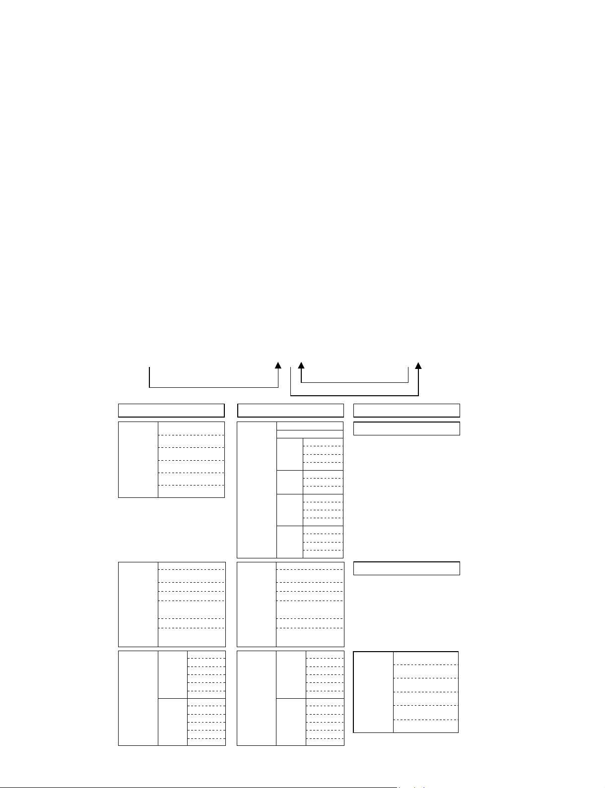
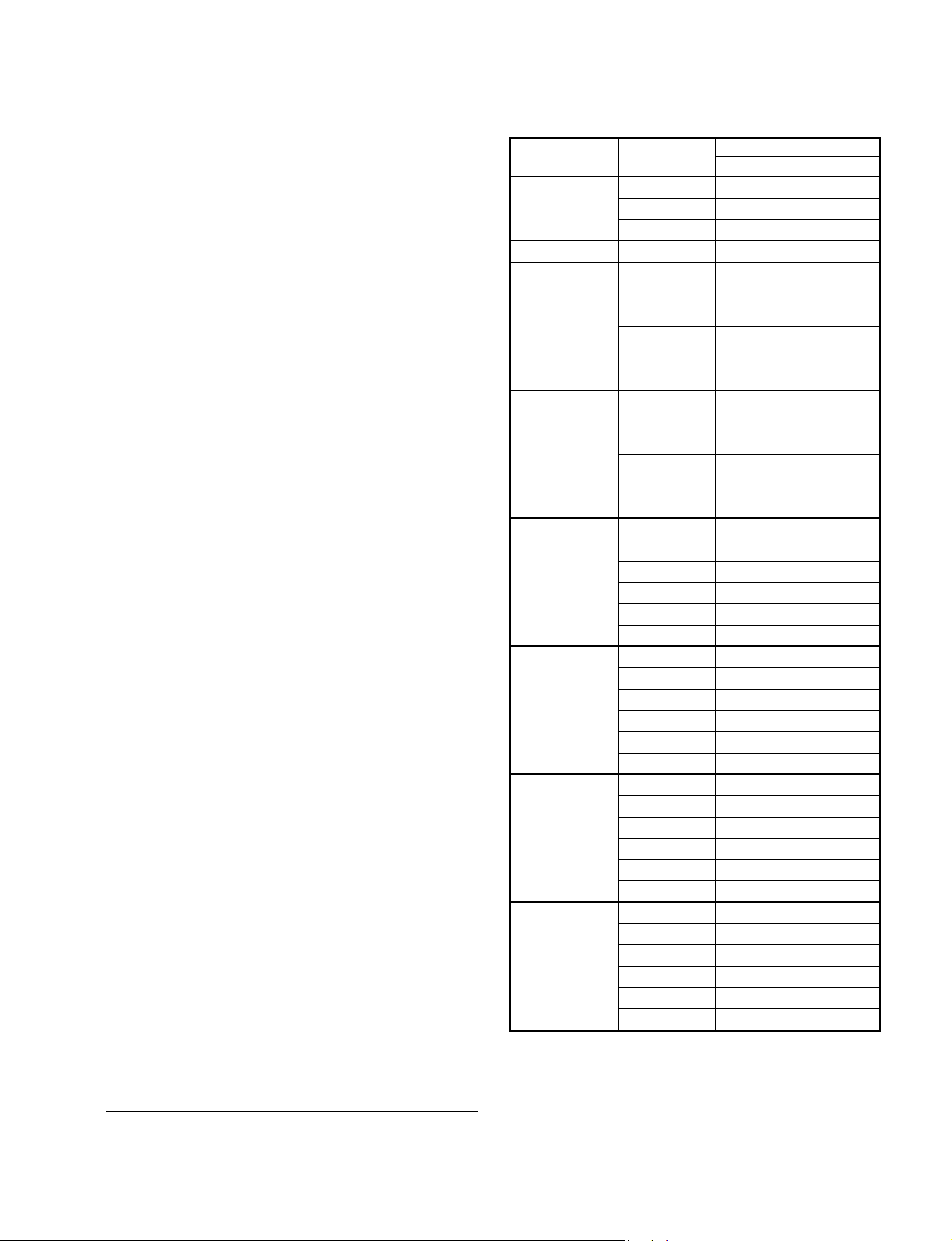
1-8. Memory
Memory structure consists of the following five memory
blocks.
1. Set memory
2. Status memory
3. Chroma memory
4. W/B memory
5. Channel memory
6. Image Flip memory
7. Picture memory
8. RCP memory
9. Fan memory
CPU internal ROM : 512 kbyte Flash Memory
CPU internal ROM : 32 kbyte
External NVM memory : 8 kbyte EEPROM
CPU ROM
Initialize
Gamma memory is actualized through Gamma mode
functions’offsetting the output values to the Contrast and
Brightness devices.
When the power plug is connected to the power line
(Standby status), all data inside the CPU ROM are
written into the NVM (Nonvolatile Memory). When the
power is turned to on, required data for the current picture,
such as status memory data, etc., are selected, and they are
written into the internal RAM.
When adjustment is carried out, the adjustment data is
stored in the NVM automatically (for items of the user
mode) or by the trigger of memory operation (for items of
the factory mode).
Adjustable items (W/B and Device Adjust) of the factory
mode are memorized into the NVM by the memory
operation. At the same time, the factory preset (adjusted)
data are all eliminated from the memory.
External NVM
CPU RAM
Memory
Active memory copy
Set Memory Set Memory Set Memory
Status
Memory
Chroma
Memory
W/B
Memory
No.01
No.02
No.03
No.04
...
No.99
NT358/443/BW60
PAL/PAL-M/N/
SECAM/BW50
15k RGB
Component (15k)
Two times speed
Component
HDTV (YPbPr)
HDTV(GBR)
(Include two times speed)
High
Middle
Computer
Low
Custom1
Custom2
Custom3
High
Middle
Low
Custom1
Custom2
Custom3
Status
Memory
Chroma
Memory
W/B
Memory
No.01
No.02
No.03
Input-A
Preset
User
Preset
Preset
PAL/PAL-M/N/
SECAM/BW50
Component (15k)
Two times speed
Component
HDTV(GBR)
(Include two times speed)
Computer
OthersOthers
No.04
...
No.99
Input-A
No.101
...
No.120
Component
No.03
No.04
...
No.99
No.03
HDMI
No.04
...
No.99
NT358/443/BW60
15k RGB
HDTV (YPbPr)
High
Middle
Low
Custom1
Custom2
Custom3
High
Middle
Low
Custom1
Custom2
Custom3
Status Memory
Chroma Memory
W/B
Memory
High
Middle
Low
Custom1
Custom2
Custom3
1-22
VPL-HS60/HS51A
Page 31

Channel
Memory
Image Flip
Memory
Picture
Memory
Video
S Video
Input-A
Component
Turn over to the upper and lower
sides
No turn over to the upper and
lower sides
Dynamic
Channel
All Input
Standard
Cinema
User1
User2
User3
Channel
Memory
Image Flip
Memory
Picture
Memory
Video
S Video
Input-A
Component
HDMIHDMI
Turn over to the upper and lower
sides
No turn over to the upper and
lower sides
Dynamic
Standard
Video
Cinema
User1
User2
User3
Dynamic
S Video
Standard
Cinema
User1
User2
User3
Dynamic
Input-A
Standard
Cinema
User1
User2
User3
Component
Dynamic
Standard
Cinema
User1
User2
User3
Dynamic
Standard
HDMI
Cinema
User1
User2
User3
Channel Memory
Image Flip Memory
Picture Memory
VPL-HS60/HS51A
1-23
Page 32

1-9. Warning on Power Connection
Use a proper power cord for your local power supply.
The United States,
Canada
Plug type VM0233 290B YP-12A COX-07 * YP332
Female end VM0089 386A YC-13B COX-02 VM0310B YC-13
Cord type SJT SJT H05VV-F H05VV-F N13237/CO-228 VCTF
Rated Voltage
& Current
Safety approval UL/CSA UL/CSA VDE VDE VDE
10A/
125V
* Use a rated plug that complies with the regulation of each country and the
specifications.
10A/
125V
Continental Europe UK, Ireland,
Australia, New
Zealand
10A/250V 10A/250V 10A/250V 7A/125V
Japan
DENANHO
1-24
VPL-HS60/HS51A
Page 33

Section 2
Electrical Adjustments
2-1. Preparations
2-1-1. Required Equipment
. Oscilloscope
Tektronix 2465 or equivalent
(bandwidth: 350 MHz or more)
. NTSC, PAL, SECAM component signal generator
Tektronix TG2000 + AVG1 (optional module) + AWVG1
(optional module) or equivalent
. VG (Programmable video signal generator)
VG854 or equivalent
. Digital voltmeter
Advantest TR6845 or equivalent
. Luminance meter
. Chrominance difference gauge
n
Perform the following adjustments at least 5 minutes after
turning on the power.
2-1-2. Factory Mode Setting
1. Press the “Setup” key on the MENU.
The “Setup” menu is displayed.
2. Set the “Status” item to “On”.
3. Exit the menu.
4. Press the keys in the following order:
“ENTER” → “ENTER” → “LEFT” → “ENTER”
5. The message “Do you wish to enter into the
FACTORY MODE? Yes:↑ No:↓ ” will be displayed.
6. Select “Yes:↑”.
m
. When returning to the USER MODE, perform item 3.
“Do you wish to return to the USER MODE? Yes:↑
No:↓ ” will be displayed. Select “Yes:↑”.
. Adjustable items (W/B and Device Adjust) of the factory
mode are memorized into the NVM by the memory
operation. At the same time, the factory preset (adjusted)
data are all eliminated from the memory.
After the unit enters and then exits the GAMMA
ADJUSTMENT MODE, be sure to perform “Save to
memory”. If a value is changed in the GAMMA
ADJUSTMENT MODE and the original value cannot be
restored, power off the unit and then power on again. If
the Advance Iris mode in “Cinema Black Pro” of
“Picture Adjust” is changed without performing “Save to
memory” the UF data remains unchanged. Further, if
“Save to memory” is performed then, the UF data
provided for each Iris mode is overwritten and lost.
VPL-HS60/HS51A
2-2. V COM Adjustment
1. Input the green-only XGA 1 Lime ON/OFF signal to
INPUT-A, and set the CONTRAST to 70.
2. Set the screen to G VCOM adjustment of “Device
Adjust.”
3. Adjust the G VCOM so that the flicker on the screen is
minimum.
4. Change the input signal to the red-only and blue-only
1 line ON/OFF signal respectively and adjust R
VCOM and B VCOM respectively so that the flicker
becomes minimum as described in step 3.
5. Save the value adjusted.
6. Set the “Image Flip” to either “V” or “HV”.
7. Input the R/G/B value adjusted as above step 5.
8. Save the value adjusted.
9. Set the “Image Flip” to “OFF”.
2-1
Page 34

2-3. Adjustment Item Initialize Data
MenuTitle ItemName
Picture
Signal
Function
Picture Mode
Adjust Picture
Contrast
Brightness
Color
Hue
Sharpness
Black Level Adj.
Gamma Correction
Color Temp.
Custom1
Gain R
Bias R
Custom2
Gain R
Bias R
Custom3
Gain R
Bias R
DDE
Cinema Black Pro
Advanced Iris
Lamp Control
RCP
Color Select
Position
Range
Color
Hue
Adjust Signal...
Dot Phase
H Size
Shift
Wide Mode
V Position(Zoom)
V Position(Sub Title)
Title Area
Smart APA
Auto Input Search
Standby Mode
Power Saving
Set
Off
Status
Memory
*1
15 (*1)
*1
*1
Dynamic Standard Cinema User1
80
55
60
50
80
Low
Off
High
Film
Off
High
Full
4
4
0
80
50
50
50
50
Off
Off
Middle
Film
Off
Low
Full
4
4
0
Memory
G
B
G
B
G
B
G
B
G
B
G
B
Memory Name
Picture Memory RCP Memory
All Input Ch.
80
50
50
50
50
Off
Off
Low
Film
Auto
Low
Full
4
4
0
80
50
50
50
50
Off
Off
Low
Film
Auto
Low
Full
User2 User3 Off User1 User2 User3
80
50
50
50
50
Off
Off
Low
Film
Auto
Low
Full
4
4
0
4
4
0
80
50
50
50
50
Off
Off
Low
Film
Auto
Low
Red
Adjust
Adjust
0
0
Full
4
4
0
*1: “Dot Phase, H Size, Shift H/V and Picture Mode” in the “INPUT SETTING” menu have an initial value
respectively in accordance with the input signal (PRESET MEMORY No.).
*2: VPL-HS51A only
Note: There are nonadjustable items in accordance with the input signal.
Red
Adjust
Adjust
0
0
Red
Adjust
Adjust
0
0
2-2
VPL-HS60/HS51A
Page 35

Memory Name
W/B Memory
Computer
High Middle Low Custom1 Custom2 Custom3
Remarks
Others
High Middle Low Custom1 Custom2 Custom3
VPL-HS60/HS51A
2-3
Page 36

MenuTitle ItemName
Setup Status
Installation
Information
W/B Gain R
Language
Input OA Signal Sel.
Color System
V Keystone
Image Flip
Background
Illumination
High Altitude Mode
Network Setting(*2)
IP Address Setup(*2)
IP Address(*2)
Subnet Mask(*2)
Default Gateway(*2)
Primary DNS(*2)
Secondary DNS(*2)
MAC Address(*2)
Speed(*2)
fH
fV
(Memory No.)
(Resolution)
ROM Version
SC ROM Version
IP ROM Version(*2)
Lamp Timer
Operation Timer
Prev. Lamp Timer
G
B
Bias R
G
B
Set
Memory
On
English
Auto
Auto
0
Off
Blue
On
Off
Indication only
Indication only
Indication only
Indication only
Indication only
Indication only
Indication only
Indication only
Indication only
Indication only
Indication only
Indication only
Indication only
Indication only
Indication only
Indication only
Indication only
Indication only
Status
Memory
Dynamic Standard Cinema User1
Memory Name
Picture Memory RCP Memory
All Input Ch.
User2 User3 Off User1 User2 User3
*1: “Dot Phase, H Size, Shift H/V and Picture Mode” in the “INPUT SETTING” menu have an initial value
respectively in accordance with the input signal (PRESET MEMORY No.).
*2: VPL-HS51A only
Note: There are nonadjustable items in accordance with the input signal.
2-4
VPL-HS60/HS51A
Page 37

Memory Name
W/B Memory
Computer
High Middle Low Custom1 Custom2 Custom3
Remarks
Others
High Middle Low Custom1 Custom2 Custom3
128
100
128
128
128
128
128
128
128
128
128
128
128
100
100
128
128
128
128
128
128
128
128
128
128
128
128
128
128
128
128
128
128
128
128
128
128
100
128
128
128
128
128
128
128
128
128
128
128
100
100
128
128
128
128
128
128
128
128
128
128
128
128
128
128
128
128
128
128
128
128
128
VPL-HS60/HS51A
2-5
Page 38

DeviceName ItemName
A/D Converter ADC/ Clamp Position
SS/
Clamp Width
R Gain(Other)
R Gain(VideoGBR)
R Gain(Component 15k)
R Gain(Component 30k)
R Gain(Component HD)
G Gain(Other)
G Gain(VideoGBR)
G Gain(Component 15k)
G Gain(Component 30k)
G Gain(Component HD)
B Gain(Other)
B Gain(VideoGBR)
B Gain(Component 15k)
B Gain(Component 30k)
B Gain(Component HD)
R Offset(Other)
R Offset(VideoGBR)
R Offset(Component 15k)
R Offset(Component 30k)
R Offset(Component HD)
G Offset(Other)
G Offset(VideoGBR)
G Offset(Component 15k)
G Offset(Component 30k)
G Offset(Component HD)
B Offset(Other)
B Offset(VideoGBR)
B Offset(Component 15k)
B Offset(Component 30k)
B Offset(Component HD)
Pre Coast 2
Post Coast 8
Bandwidth 3
SonG Bias Current
SonG Hysterisis
SonG Thresh
Video Pos Thresh
Video Bias Current
Video Hysterisis
Video Thresh
VS Pol Gain
HS Pol Gain
Back VS Pol Gain
Back HS Pol Gain
VS Sep Sens
Set Memory Status Memory Chroma Memory
1
1
1
1
1
1
1
0
0
0
0
0
*2
*2
2
8
3
NT358/NT443
/BW60
Memory Name
Pal/Pal-M/N/
Secam/BW50
Note: There are nonadjustable items in accordance with the input signal.
*1: Depends on the color system and the input terminal.
*2: Depend on the input signal.
15kRGB
Component
(15k)
Two times speed
Component
HDTV
(YPbPr)
HDTV(GBR)
Include two times speed
2-6
VPL-HS60/HS51A
Page 39

Channel Memory
Memory Name
Video S Video Input-A Component
HDMI
Image Flip Memory
Turn over to the upper
and lower sides
No turn over to the
upper and lower sides
Fan Memory
Remarks
–
–
–
–
–
–
–
–
–
–
–
–
–
–
–
–
–
–
–
–
–
–
–
–
–
–
–
–
–
–
80
–
80
–
80
–
80
–
80
–
80
–
80
–
80
–
80
–
80
–
80
–
80
–
80
–
80
–
80
–
100
–
100
–
128
–
128
–
128
–
100
–
100
–
100
–
100
–
100
–
100
–
100
–
128
–
128
–
128
–
–
–
80
80
80
–
–
80
80
80
–
–
80
80
80
–
–
128
128
128
–
–
100
100
100
–
–
128
128
128
–
–
–
–
–
–
–
–
–
–
–
–
–
–
–
–
–
–
–
–
–
–
–
–
–
–
–
–
–
–
VPL-HS60/HS51A
2-7
Page 40

DeviceName ItemName
Chroma/D.Comb
Panel Driver P.Drv
Chroma/
SH/
Other/
Ch1 Gain(NTSC3.58)
Ch1 Gain(Other)
Ch2 Gain(NTSC3.58)
Ch2 Gain(Other)
Video Sharp
Video Brt
Video Cont
Video Color
Video Hue
LCBW
Y-DeLay
Ch3 Gain(NTSC3.58)
Ch3 Gain(Other)
Ch4 Gain(NTSC3.58)
Ch4 Gain(Other)
Luma COR
Luma F0
Luma SHP
Chm COR
Chm F0
Chm SHP
AOSL
Status 1
Status 2
Offset R
Offset G
Offset B
V Common R
V Common G
V Common B
Psig 1 R
Psig 1 G
Psig 1 B
Psig 2 R
Psig 2 G
Psig 2 B
Signal Center R
Signal Center G
Signal Center B
Gain R
Gain G
Gain B
GDCFB Auto
SH1
V Com Ptn Enb
Installation
Set Memory Status Memory Chroma Memory
*1
–
Indication only
Indication only
16
16
16
86
86
86
31
31
31
158
158
158
0
22
Adjustment is impossible
0
NT358/NT443
/BW60
0
152
79
64
0
0
0
0
0
0
0
Memory Name
Pal/Pal-M/N/
Secam/BW50
0
134
81
64
0
0
0
0
0
0
0
Note: There are nonadjustable items in accordance with the input signal.
*1: Depends on the color system and the input terminal.
*2: Depend on the input signal.
15kRGB
–
–
–
–
–
–
–
–
–
–
–
Component
(15k)
–
–
–
–
–
–
–
–
–
–
–
Two times speed
Component
–
–
–
–
–
–
–
–
–
–
–
HDTV
(YPbPr)
–
–
–
–
–
–
–
–
–
–
–
HDTV(GBR)
Include two times speed
–
–
–
–
–
–
–
–
–
–
–
2-8
VPL-HS60/HS51A
Page 41

Channel Memory
Video S Video Input-A Component
18
31
31
31
31
31
31
31
–
–
–
–
Memory Name
–
–
–
–
HDMI
–
–
–
–
Image Flip Memory
Turn over to the upper
and lower sides
No turn over to the
upper and lower sides
Fan Memory
Remarks
6
31
31
31
31
6
31
31
31
31
–
–
–
–
–
–
–
–
–
–
–
–
–
–
–
116
116
116
101
101
101
116
116
116
101
101
101
VPL-HS60/HS51A
2-9
Page 42

DeviceName ItemName
Display
Engine
DE/
CSC/
Sub Cont
Sub Brt
LUT Through
UF SW
APC Thres
HST Position
HST Phase
Drift On
HPC R
HPC G
HPC B
R HPC Data 0
G HPC Data 0
B HPC Data 0
R HPC Data 1
G HPC Data 1
B HPC Data 1
USC On
HPF On
HPF TAP
HPF AAC
UGM DRC On
UGM Sub Gain
UGM Sub Bias
RCP CSC Off
UGM On R
UGM On G
UGM On B
USC Limit On
USC Limit R
USC Limit G
USC Limit B
RCP Hue Through
RCP Gamma R On
RCP Gamma G On
RCP Gamma B On
CSC Mode
Set Memory Status Memory Chroma Memory
0
0
0
1
7
7
116
0
Indication only
Indication only
Indication only
463
463
463
463
463
463
1
1
0
96
0
1
1
1
1
0
4095
4095
4095
1
0
0
0
–
*2
*2
NT358/NT443
/BW60
Memory Name
Pal/Pal-M/N/
Secam/BW50
Note: There are nonadjustable items in accordance with the input signal.
*1: Depends on the color system and the input terminal.
*2: Depend on the input signal.
15kRGB
Component
(15k)
Two times speed
Component
HDTV
(YPbPr)
HDTV(GBR)
Include two times speed
2-10
VPL-HS60/HS51A
Page 43

Channel Memory
Memory Name
Video S Video Input-A Component HDMI
Image Flip Memory
Turn over to the upper
and lower sides
No turn over to the
upper and lower sides
Fan Memory
Remarks
VPL-HS60/HS51A
2-11
Page 44

DeviceName ItemName
Other Temp/
Fan/
Fan1/
Fan2/
Fan3/
Other/
Fan/
Fan1/
Fan2/
Fan3/
Iris/
Thresh Lamp
Thresh Panel
Thresh Atmos
Hi Alt Const
High Alt Cofe
Cont Max
Speed Max
Speed Min
Reg Max
Reg Min
Cont Max
Speed Max
Speed Min
Reg Max
Reg Min
Cont Max
Speed Max
Speed Min
Reg Min
Synchronous
X Tilt
Y Tilt
Temp Lamp
Temp Panel
Temp Atomos
Reg Adj Cont
Reg Max
Reg Min
Reg Max
Reg Min
Reg Max
Reg Min
Iris Adj
Open Reg
Close Reg
Open Hall
Close Hall
Set Memory Status Memory Chroma Memory
1
–
–
Indication only
Indication only
Indication only
Adjustment is impossible
0
0
255
Indication only
Indication only
NT358/NT443
/BW60
Memory Name
Pal/Pal-M/N/
Secam/BW50
Note: There are nonadjustable items in accordance with the input signal.
*1: Depends on the color system and the input terminal.
*2: Depend on the input signal.
15kRGB
Component
(15k)
Two times speed
Component
HDTV
(YPbPr)
HDTV(GBR)
Include two times speed
2-12
VPL-HS60/HS51A
Page 45

Channel Memory
Memory Name
Video S Video Input-A Component HDMI
Image Flip Memory
Turn over to the upper
and lower sides
Adjustment is impossible
Adjustment is impossible
Adjustment is impossible
Adjustment is impossible
Adjustment is impossible
Adjustment is impossible
Adjustment is impossible
Adjustment is impossible
Adjustment is impossible
Adjustment is impossible
Adjustment is impossible
Adjustment is impossible
Adjustment is impossible
Adjustment is impossible
Adjustment is impossible
Adjustment is impossible
Adjustment is impossible
No turn over to the
upper and lower sides
Adjustment is impossible
Adjustment is impossible
Adjustment is impossible
Adjustment is impossible
Adjustment is impossible
Adjustment is impossible
Adjustment is impossible
Adjustment is impossible
Adjustment is impossible
Adjustment is impossible
Adjustment is impossible
Adjustment is impossible
Adjustment is impossible
Adjustment is impossible
Adjustment is impossible
Adjustment is impossible
Adjustment is impossible
Fan Memory
Remarks
Adjustment is impossible
Adjustment is impossible
Adjustment is impossible
Adjustment is impossible
Adjustment is impossible
Adjustment is impossible
VPL-HS60/HS51A
2-13
Page 46

DeviceName ItemName
I/P Ip/
Ip2/
CTI Tap
CTI Shift
CTI Limit
CTI Gain
Sharp Limit
MD Thresh C
MD Thresh 0
VS
Continue
Edit Detect
Indicator
Manual
Manual Pair
Manual State
Field Times
Noise Thresh
Disp Area
VS Limit
VS Core
Hysteresis
Hysteresis Data
22 Pre Post Rate
22 Pre Post Thresh
Film Times 22
YNR On
CNR On
Sudare Rate 32
Sudare Thresh 32
Sudare Rate 22
Sudare Thresh 22
UV PhaseSel
Set Memory Status Memory Chroma Memory
3
1
128
20
255
8
16
1
1
0
0
0
0
0
2
4
0
64
4
1
2
15
2
3
0
0
4
64
4
40
*2
NT358/NT443
/BW60
Memory Name
Pal/Pal-M/N/
Secam/BW50
Note: There are nonadjustable items in accordance with the input signal.
*1: Depends on the color system and the input terminal.
*2: Depend on the input signal.
15kRGB
Component
(15k)
Two times speed
Component
HDTV
(YPbPr)
HDTV(GBR)
Include two times speed
2-14
VPL-HS60/HS51A
Page 47

Channel Memory
Memory Name
Video S Video Input-A Component HDMI
Image Flip Memory
Turn over to the upper
and lower sides
No turn over to the
upper and lower sides
Fan Memory
Remarks
VPL-HS60/HS51A
2-15
Page 48

2-4. White Balance Adjustment on
Servicing
2-4-1. Computer
Preparation
5. Repeat steps 3 and 4, and adjust each GAIN and BIAS
of RGB so that x and y are within the following
specification.
x: 0.284 ± 0.002
y: 0.298 ± 0.003
6. Save the adjustment values.
1. Set the unit from the menu as follows.
Picture Mode: Cinema
Adjust Picture
Contrast: 80
Brightness: 50
Gamma Correction: OFF
Cinema Black Pro:
Iris Control: OFF
Lamp Control: Low
2. Set each mode of “Color Temp:” as follows.
Gain: 128
Bias: 128
3. Set INPUT-A Signal Sel. to “Computer”.
Adjustment
1. High
1. Set “Color Temp:” to High.
2. Input WXGA 80 IRE Window white (3 colors: RGB)
to INPUT-A and adjust the GAIN of G of white
balance so that the chromaticity (y80) is within
specification.
x80: 0.284 ±0.002
y80: 0.298 ±0.003
Then, set the reference color as follows and adjust the
GAIN of colors other than the reference color of white
balance so that the chromaticity (x80 and y80) is
within specification.
x80 > 0.294: B reference
y80 < 0.294: R reference
3. Input WXGA 20 IRE Window white (3 colors: RGB)
to INPUT-A and adjust the BIAS of colors other than
G of white balance so that the chromaticity (x20 and
y20) is within specification.
x20: 0.294 ±0.002
y20: 0.310 ±0.003
4. Input WXGA 80 IRE Window white (3 colors: RGB)
to INPUT-A and adjust the GAIN of colors other than
the reference color of white balance so that the
chromaticity (x80 and y80) is within specification.
2. Middle
1. Set “Color Temp:” to Middle.
2. Input WXGA 80 IRE Window white (3 colors: RGB)
to INPUT-A and adjust the GAIN of G of white
balance so that the chromaticity (y80) is within
specification.
x80: 0.294 ± 0.002
y80: 0.310 ± 0.003
Then, set the reference color as follows and adjust the
GAIN of colors other than the reference color of white
balance so that the chromaticity (x80 and y80) is
within specification.
x80 > 0.294: B reference
y80 < 0.294: R reference
3. Input WXGA 20 IRE Window white (3 colors: RGB)
to INPUT-A and adjust the BIAS of colors other than
G of white balance so that the chromaticity (x20 and
y20) is within specification.
x20: 0.294 ± 0.002
y20: 0.310 ± 0.003
4. Input WXGA 80 IRE Window white (3 colors: RGB)
to INPUT-A and adjust the GAIN of colors other than
the reference color of white balance so that the
chromaticity (x80 and y80) is within specification.
5. Repeat steps 3 and 4, and adjust each GAIN and BIAS
of RGB so that x and y are within the following
specification.
x: 0.294 ± 0.002
y: 0.310 ± 0.003
6. Save the adjustment values.
3. Low
1. Set “Color Temp:” to Low.
2. Input WXGA 20 IRE Window white (3 colors: RGB)
to INPUT-A and adjust the BIAS of colors other than
G of white balance so that the chromaticity (x20 and
y20) is within specification.
x20: 0.313 ± 0.002
y20: 0.329 ± 0.003
2-16
VPL-HS60/HS51A
Page 49

3. Input WXGA 80 IRE Window white (3 colors: RGB)
to INPUT-A and adjust the GAIN of colors other than
R of white balance so that the chromaticity (x80 and
y80) is within specification.
4. Repeat steps 2 and 3, and adjust each GAIN and BIAS
of RGB so that x and y are within the following
specification.
x: 0.313 ± 0.002
y: 0.329 ± 0.003
5. Save the adjustment values.
4. Custom1/2/3
1. Copy the values adjusted in “1. High”, “2. Middle”
and “3. Low” as follows.
Custom1: High
Custom2: Middle
Custom3: Low
2. Save the adjustment values.
2-4-2. Video
Adjustment
The adjustment procedures of “1. High”, “2. Middle” and
“3. Low” modes are the same as those in “2-4-1.
Computer”.
m
. Use the two times speed Component or two times speed
VideoGBR signal as the input signal according to step 3
in Preparation.
. Use the reference color of High, Middle and Low same
as that in “2-4-1. Computer”.
Preparation
1. Set the unit from the menu as follows.
Picture Mode: Cinema
Adjust Picture
Contrast: 80
Brightness: 50
Color: 50
Hue: 50
Sharpness: 50
Black Level Adj.: OFF
Gamma Correction: OFF
Cinema Black Pro:
Iris Control: OFF
Lamp Control: Low
2. Set each mode of “Color Temp:” as follows.
Gain: 150
Bias: 127
3. Set INPUT-A Signal Sel. to “Component” or “Video
GBR”.
VPL-HS60/HS51A
2-17
Page 50

Page 51

Section 3
Semiconductors
IC
24LC21AT-I/SN
24LC256T-I/SNG
BR24L02F-WE2
ICS342M-05LF
M24256-BWMN6T
M24C64-WMN6T(B)
MM1115XFBE
NE57814DD.518
ST24FC21M6TR
TL431BCDR2
1
TOP VIEW
8PIN SOP
74VHC02MTCX
SN74LV00APWR
SN74LV125APWR
SN74LVC125APWR-12
AIC1117A-18PYJTR
AIC1117A-25PEJTR
AIC1117A-33PEJTR
AIC1117A-33PYJTR
AIC1117A-50PEJTR
AIC1117A-50PYJTR
AIC1117A-PEJTR
LM1117MPX-1.8
TL431CPK-E2
1
2
3
BA00ASFP-E2
BA00BC0WFP-E2
1
2
3
4
5
CXD9809GF
INDEX
A
1
BOTTOM VIEW
292PIN PBGA
DP83847ALQA56A/J5000283
1
BOTTOM VIEW
56PIN LLP
HD64F2378BVFQ35V
HD64F2378VFQ34V
M95640-WDW6TG
1
TOP VIEW
8PIN TSOP
MBM29LV160BE-90TN-801IP100
1
TOP VIEW
48PIN TSOP
MCZ3001UB
1
TOP VIEW
14PIN SSOP
AD9981KSTZ-95
1
TOP VIEW
80PIN QFP
CXA7004R-T4
LC4032V-75TN48C-DLY2
1
TOP VIEW
48PIN FQFP
CXD9760GP
INDEX
A
1
BOTTOM VIEW
329PIN PBGA
1
TOP VIEW
144PIN FQFP
K4D263238F-UC50T
1
100PIN TQFP
LTC3728LXCUH#TR-R5
1
BOTTOM VIEW
321PIN QFN
1
TOP VIEW
32PIN SSOP
MM1571JNLE
MM1573DNLE
5
4
1
2
3
MT48LC2M32B2P-6:G
1
TOP VIEW
86PIN TSOP
VPL-HS60/HS51A
3-1
Page 52

IC
MX29LV800TTC-70G-89PW
1
TOP VIEW
48PIN SOP
MZ1540
1
MARKING SIDE VIEW
NET+NS7520B-1-C55
INDEX
A
1
BOTTOM VIEW
177PIN PBGA
PQ20WZ1UJ00H
1
2
3
4
5
PW168B-10VL
INDEX
A
1
BOTTOM VIEW
352PIN PBGA
S-80928CNMC-G8YT2G
SN74LVC1G14DCKR
TC7SH00FU-TE85R
TK11133CSCL-G
45
SN74AHCT541PWR
SN74LVC244APWR
SN74LVC541APWR
1
TOP VIEW
20PIN SSOP
SN74LV4052APWR
TC74VHC123AFT(EL)
1
TOP VIEW
16PIN SSOP
ST72T631K4M1-201
TK11100CSCB-G
465
123
6PIN CHIP
UPD64083GF-3BA
1
TOP VIEW
100PIN QFP
NJM2904V(TE2)
NJM4556AV(TE2)
TA75W393FU
TA75W393FU-TE12R
1
TOP VIEW
8PIN SSOP
NJM78M12DL1A-TE1
3
2
1
3-2
123
5PIN CHIP
SAA7119E/V2
INDEX
A
1
BOTTOM VIEW
156PIN BGA
SII9993CTG100
1
TOP VIEW
100PIN FQFP
1
TOP VIEW
34PIN SSOP
STR-A6169
1
TOP VIEW
8PIN DIP
TE8200PF
1
TOP VIEW
48PIN QFP
VPL-HS60/HS51A
Page 53

Transistor, Diode
CATHODE
ANODE
2SA1162-G
2SA1162-YG-TE85L
2SA1576A-T106-QR
2SC2712-YG
2SC2712-YG-TE85L
2SC4081-R
2SC4081T106R
DTA144EUA-T106
DTC114EU
DTC114EUAFT106
DTC114EUA-T106
DTC144EUA-T106
C
B
E
2SA1213Y-TE12L
B
C
E
2SK2876-01MR-F122
G
D
S
FDS6986S
8
7
6
5
1
2
3
4
8
7
6
1
2
3
4
HN1B01FU-TE85R
6
5
1
2
6
3
1
2
5
4
3
SSM6N15FU(TE85R)
D1
G2
S2
S1
G1
D2
1SS355TE-17
MA111-TX
D1FL20U-TA
D1FL40
D1FS4A-TA
D2FS6-TA
ANODE
ANODE
5
CATHODE
CATHODE
1SS388(TPL3)
UDZSTE-1722B
D1UBA80
UDZS-TE17-22B
UDZSTE-175.6B
4
ANODE
4
3
1
CATHODE
BZA456A/G.115
6
1
2
3
6
1
2
3
5
4
5
4
2
1
D6SB80
4
3
2
2SJ463A-T1
G
S
FDC658P
RTQ035P02TR
3
2
1
4
3
2
VPL-HS60/HS51A
BZT03-C180
D
DAN202K
DAN202K-T-146
DAN202U
DAN202UT106
DAP202K
4
5
6
5
6
1
D10SC4M
D10SC6M
1
2
3
1
2
3
DAP202K-T-146
3
2
1
3
2
1
3-3
Page 54

Diode
ERA22-08KFLB
UF4005/23
CATHODE
ANODE
HN1D03FU-TE85L
HN1D03FU-TE85R
6
1
2
3
6
5
1
2
3
MA3J14700LSO
MA133
MA133-TX
3
RD12SB-T1
RD3.9SB
SEC1801C
SEC1901C
RD3.9SB-T1
RD5.6SB-T1
ANODECATHODE
2
SEC2422C
1
1
2
CATHODE
ANODE
RD18M-T1B1
RD33M-B
5
4
4
RD33M-T1B
RD7.5M-B2
RD7.5M-T1B
3
2
1
3
2
1
RM11C
RM11C-V1
CATHODE
1
2
1
2
NSCW215T
ANODE
3-4
3
ANODE
RSB6.8SFTE61
CATHODE
VPL-HS60/HS51A
Page 55

4-1. Notes on Repair Parts
1. Safety Related Components Warning
w
Components marked ! are critical to safe operation.
Therefore, specified parts should be used in the case of
replacement.
2. Standardization of Parts
Some repair parts supplied by Sony differ from those
used for the unit. These are because of parts commonality and improvement.
Parts list has the present standardized repair parts.
3. Stock of Parts
Parts marked with “o” at SP (Supply Code) column of
the spare parts list may not be stocked. Therefore, the
delivery date will be delayed.
Section 4
Spare Parts
4. Harness
Harnesses with no part number are not registered as
spare parts.
In need of repair, get components shown in the list and
repair using them.
VPL-HS60/HS51A
4-1
Page 56

Base Block
4-2. Exploded Views
FOR VPL-HS51A
5
BTP
3 x 12
3
7
8
A
B
2
8
BTP
3 x 12
BTP
3 x 12
BTP
3 x 12
6
4
A
1
B
No. Part No. SP Description
1 A-1057-960-A s NF MOUNT
2 A-1164-047-A s Q COMPL
(FOR VPL-HS51A)
3 ! X-2025-173-4 s COVER ASSY,LAMP
4 ! 2-178-507-04 s COVER, REAR
5 2-345-361-01 s COVER, EITHER
(FOR VPL-HS51A)
No. Part No. SP Description
6 4-091-838-02 s SCREW M5X5, SPECIAL
7 4-099-122-02 s SCREW +BV 3X70 TYPE 2, SPECIAL
8 4-382-854-01 s SCREW (M3X8), P, SW (+)
(FOR VPL-HS51A)
7-685-548-19 s SCREW +BTP 3X12 TYPE2 N-S
4-2
VPL-HS60/HS51A
Page 57

GA and GB Block
BTP3 x 12
BTP3 x 12
B
102
BTP
3 x 12
B
A
BTP
3 x 12
A
103
101
No. Part No. SP Description
101 A-1070-686-A s MOUNTED CIRCUIT BOARD, GA
102 A-1070-687-A s MOUNTED CIRCUIT BOARD, GB
103 1-543-993-11 s CORE, FERRITE
7-685-548-19 s SCREW +BTP 3X12 TYPE2 N-S
VPL-HS60/HS51A
4-3
Page 58

Main Board and Rear Block
BTP
3 x 12
A
205
202
BTP
3 x 12
BTP
3 x 12
BTP
3 x 12
A
PSW
4 x 8
204
BTP
3 x 12
See GA and GB Block
BTP
3 x 12
K3 x 6
TO
F MOUNT
201
4-4
203
BTP
3 x 12
No. Part No. SP Description
201 A-1057-965-A s MOUNTED CIRCUIT BOARD, V
202 A-1164-049-A s MOUNTED CIRCUIT BOARD, C
(FOR VPL-HS60)
A-1164-045-A s MOUNTED CIRCUIT BOARD, C
(FOR VPL-HS51A)
203 ! 1-787-404-11 s DC FAN
204 ! 1-818-098-21 s INLET, AC (WITH NOISE FILTER)
205
2-188-260-01 s LABEL, CONNECTOR
7-682-247-09 s SCREW +K 3X6
7-682-961-01 s SCREW +PSW 4X8
7-685-548-19 s SCREW +BTP 3X12 TYPE2 N-S
VPL-HS60/HS51A
Page 59

BVTP
3 x 20
Lamp Power Supply Block
BTP
3 x 12
A
301
302
See Optics Block 1, 2
BTP
3 x 12
303
304
B
C
A
305
C
304
B
304
304
306
No. Part No. SP Description
301 ! 1-468-866-11 s LAMP POWER SUPPLY BLOCK
302 1-543-993-11 s CORE, FERRITE
303 ! 1-787-149-11 s D.C. FAN (SIROCCO)
304 4-089-523-01 s SPRING, LAMP
305 4-089-560-02 s LENS, CONCAVE
7-685-548-19 s SCREW +BTP 3X12 TYPE2 N-S
7-685-651-79 s SCREW +BVTP 3X20 TYPE2 IT-3
VPL-HS60/HS51A
4-5
Page 60

Top Panel Block
BTP
3 x 12
406
BTP
3 x 12
BTP
3 x 12
402
BTP
3 x 12
BTP
3 x 12
408
409
410
BVTP
3 x 8
407
BTP
3 x 12
401
405
403
No. Part No. SP Description
401 A-1057-962-A s MOUNTED CIRCUIT BOARD, L
402 A-1057-964-A s MOUNTED CIRCUIT BOARD, U
403 A-1057-969-A s MOUNTED CIRCUIT BOARD, HA
404 A-1057-970-A s MOUNTED CIRCUIT BOARD, HB
405 A-1076-324-A s MOUNTED CIRCUIT BOARD, F
No. Part No. SP Description
406 A-1086-806-A s MOUNTED CIRCUIT BOARD, TA
407 ! 1-576-701-21 s THERMOSTAT
408 ! 1-787-404-11 s DC FAN
409 ! 1-787-231-21 s D.C. FAN (SIROCCO)
410 2-348-149-01 s TAPPING SCREW +PTP 4X45
7-685-548-19 s SCREW +BTP 3X12 TYPE2 N-S
7-685-546-19 s SCREW +BVTP 3X8 TYPE2 IT-3
4-6
404
VPL-HS60/HS51A
Page 61

501
503
505
505
505
See Optics Block 2
502
B2 x 8
PWH M2 x 5
504
Optics Block 1
No. Part No. SP Description
501 A-1157-814-A s OPTICS UNIT ASSY
502 A-1157-815-A s PRISM BLOCK ASSY
503 A-1163-897-A s PROJECTION LENS ASSY (FOR VPL-HS60)
A-1166-875-A s PROJECTION LENS ASSY (FOR VPL-HS51A)
504 2-188-259-02 s COVER, LENS
505 4-382-854-11 s SCREW (M3X10), P, SW (+)
7-621-772-40 s SCREW +B 2X8
7-681-000-00 s SCREW +PWH M2X5
VPL-HS60/HS51A
4-7
Page 62

Optics Block 2
604
PWH
M2 x 5
PWH
M2 x 5
603
PWH
M2 x 5
PWH
M2 x 5
605
602
PWH
M2 x 5
601
No. Part No. SP Description
601 A-1095-034-A s PS ASSY
602 1-788-185-12 s IRIS UNIT
603 A-1163-898-A s PANEL (R) ASSY, IN-POLARIZER
604 A-1095-036-A s PANEL (G) ASSY, IN-POLARIZER
605 A-1095-037-A s PANEL (B) ASSY, IN-POLARIZER
7-681-000-00 s SCREW +PWH M2X5
7-685-147-21 s SCREW +P 3X10 TYPE2 SLIT
4-8
VPL-HS60/HS51A
Page 63

4-3. Electrical Parts List
------C BOARD
-------
*1:[VPL-HS60]
*2:[VPL-HS51A]
Ref. No.
or Q'ty Part No. SP Description
1pc *1 A-1164-049-A s MOUNTED CIRCUIT BOARD, C
1pc *2 A-1164-045-A s MOUNTED CIRCUIT BOARD, C
C100 1-126-205-11 s CAPACITOR,ELECT 47MF/6.3
C103 1-107-820-11 s CAPACITOR,CHIP CERAMIC 0.1MF F
C106 1-107-820-11 s CAPACITOR,CHIP CERAMIC 0.1MF F
C107 1-107-820-11 s CAPACITOR,CHIP CERAMIC 0.1MF F
C200 *2 1-165-908-11 s CAP, CERAMIC 1MF B 1608
C201 *2 1-119-667-11 s CAPACITOR CERAMIC 22MF/10V(F)
C202 *2 1-164-862-11 s CAPACITOR,CHIP CERAMIC 33PF/50
C203 *2 1-164-862-11 s CAPACITOR,CHIP CERAMIC 33PF/50
C204 *2 1-107-820-11 s CAPACITOR,CHIP CERAMIC 0.1MF F
C205 *2 1-107-820-11 s CAPACITOR,CHIP CERAMIC 0.1MF F
C206 *2 1-164-943-11 s CAPACITOR,CHIP CERAMIC 0.01MF
C207 *2 1-107-820-11 s CAPACITOR,CHIP CERAMIC 0.1MF F
C208 1-107-820-11 s CAPACITOR,CHIP CERAMIC 0.1MF F
C209 1-107-820-11 s CAPACITOR,CHIP CERAMIC 0.1MF F
C210 1-126-205-11 s CAPACITOR,ELECT 47MF/6.3
C400 1-126-205-11 s CAPACITOR,ELECT 47MF/6.3
C401 1-107-820-11 s CAPACITOR,CHIP CERAMIC 0.1MF F
C402 1-107-820-11 s CAPACITOR,CHIP CERAMIC 0.1MF F
C403 1-125-777-11 s CAPACITOR CERAMIC 0.1MF/10V
C404 1-107-820-11 s CAPACITOR,CHIP CERAMIC 0.1MF F
C405 1-126-209-11 s CAPACITOR,ELECT 100MF/4V
C406 1-107-820-11 s CAPACITOR,CHIP CERAMIC 0.1MF F
C407 1-126-209-11 s CAPACITOR,ELECT 100MF/4V
C408 1-107-820-11 s CAPACITOR,CHIP CERAMIC 0.1MF F
C409 1-107-820-11 s CAPACITOR,CHIP CERAMIC 0.1MF F
C410 1-126-209-11 s CAPACITOR,ELECT 100MF/4V
C411 1-135-834-11 s CAPACITOR, CERAMIC 2200000PF
C412 1-126-209-11 s CAPACITOR,ELECT 100MF/4V
C413 1-107-820-11 s CAPACITOR,CHIP CERAMIC 0.1MF F
C414 1-126-209-11 s CAPACITOR,ELECT 100MF/4V
C415 1-162-970-11 s CAPACITOR CERAMIC 0.01MF/25V B
C416 1-107-820-11 s CAPACITOR,CHIP CERAMIC 0.1MF F
C417 1-107-820-11 s CAPACITOR,CHIP CERAMIC 0.1MF F
C418 1-164-943-11 s CAPACITOR,CHIP CERAMIC 0.01MF
C419 1-107-820-11 s CAPACITOR,CHIP CERAMIC 0.1MF F
C420 1-107-820-11 s CAPACITOR,CHIP CERAMIC 0.1MF F
C421 1-119-923-11 s CAPACITOR,CHIP CERAMIC 0.047MF
C422 1-164-943-11 s CAPACITOR,CHIP CERAMIC 0.01MF
C423 1-137-710-91 s CAPACITOR,CERAMIC 10MF B(2012)
C424 1-164-943-11 s CAPACITOR,CHIP CERAMIC 0.01MF
C425 1-164-943-11 s CAPACITOR,CHIP CERAMIC 0.01MF
C426 1-164-943-11 s CAPACITOR,CHIP CERAMIC 0.01MF
C427 1-107-820-11 s CAPACITOR,CHIP CERAMIC 0.1MF F
C428 1-107-820-11 s CAPACITOR,CHIP CERAMIC 0.1MF F
C429 1-107-820-11 s CAPACITOR,CHIP CERAMIC 0.1MF F
C430 1-164-505-11 s CAPACITOR,CHIP CERAMIC 2.2MF
C432 1-107-820-11 s CAPACITOR,CHIP CERAMIC 0.1MF F
C433 1-126-209-11 s CAPACITOR,ELECT 100MF/4V
C500 1-125-777-11 s CAPACITOR CERAMIC 0.1MF/10V
C501 1-164-392-11 s CAPACITOR CERAMIC 390PF/50V CH
C503 1-164-858-11 s CAPACITOR,CERAMIC 22PF/50V
C504 1-164-858-11 s CAPACITOR,CERAMIC 22PF/50V
C506 1-164-939-11 s CAPACITOR,CHIP CERAMIC 2200PF
(C BOARD)
Ref. No.
or Q'ty Part No. SP Description
C507 1-125-777-11 s CAPACITOR CERAMIC 0.1MF/10V
C508 1-107-820-11 s CAPACITOR,CHIP CERAMIC 0.1MF F
C509 1-126-208-21 s CAPACITOR, ELECT 47MF(4.3X5.5)
C510 1-125-777-11 s CAPACITOR CERAMIC 0.1MF/10V
C511 1-107-820-11 s CAPACITOR,CHIP CERAMIC 0.1MF F
C512 1-125-777-11 s CAPACITOR CERAMIC 0.1MF/10V
C513 1-126-209-11 s CAPACITOR,ELECT 100MF/4V
C514 1-107-820-11 s CAPACITOR,CHIP CERAMIC 0.1MF F
C515 1-125-777-11 s CAPACITOR CERAMIC 0.1MF/10V
C516 1-107-820-11 s CAPACITOR,CHIP CERAMIC 0.1MF F
C517 1-126-206-11 s CAPACITOR, ELECT 100MF/6.3V
C518 1-125-777-11 s CAPACITOR CERAMIC 0.1MF/10V
C519 1-165-908-11 s CAP, CERAMIC 1MF B 1608
C520 1-107-820-11 s CAPACITOR,CHIP CERAMIC 0.1MF F
C521 1-107-820-11 s CAPACITOR,CHIP CERAMIC 0.1MF F
C522 1-137-710-91 s CAPACITOR,CERAMIC 10MF B(2012)
C523 1-126-208-21 s CAPACITOR, ELECT 47MF(4.3X5.5)
C524 1-107-820-11 s CAPACITOR,CHIP CERAMIC 0.1MF F
C525 1-107-820-11 s CAPACITOR,CHIP CERAMIC 0.1MF F
C526 1-107-820-11 s CAPACITOR,CHIP CERAMIC 0.1MF F
C527 1-126-209-11 s CAPACITOR,ELECT 100MF/4V
C528 1-125-777-11 s CAPACITOR CERAMIC 0.1MF/10V
C529 1-125-777-11 s CAPACITOR CERAMIC 0.1MF/10V
C530 1-125-777-11 s CAPACITOR CERAMIC 0.1MF/10V
C531 1-125-777-11 s CAPACITOR CERAMIC 0.1MF/10V
C532 1-125-777-11 s CAPACITOR CERAMIC 0.1MF/10V
C533 1-125-777-11 s CAPACITOR CERAMIC 0.1MF/10V
C534 1-126-205-11 s CAPACITOR,ELECT 47MF/6.3
C535 1-125-777-11 s CAPACITOR CERAMIC 0.1MF/10V
C536 1-125-777-11 s CAPACITOR CERAMIC 0.1MF/10V
C537 1-126-246-11 s CAPACITOR ELECT 220MF/4V(CHIP)
C538 1-164-858-11 s CAPACITOR,CERAMIC 22PF/50V
C539 1-128-013-11 s CAPACITOR ELECT 1MF/50V
C540 1-128-004-11 s CAPACITOR ELECT 10MF/16V(CHIP)
C541 1-164-854-11 s CAPACITOR,CHIP CERAMIC 15PF/50
C542 1-164-854-11 s CAPACITOR,CHIP CERAMIC 15PF/50
C543 1-164-935-11 s CAPACITOR,CHIP CERAMIC 470PF
C544 1-107-820-11 s CAPACITOR,CHIP CERAMIC 0.1MF F
C545 1-128-013-11 s CAPACITOR ELECT 1MF/50V
C546 1-126-206-11 s CAPACITOR, ELECT 100MF/6.3V
C547 1-164-854-11 s CAPACITOR,CHIP CERAMIC 15PF/50
C548 1-115-339-11 s CAPACITOR,CERAMIC 0.1MF/50V
C549 1-128-004-11 s CAPACITOR ELECT 10MF/16V(CHIP)
C550 1-164-505-11 s CAPACITOR,CHIP CERAMIC 2.2MF
C551 1-126-204-11 s CAPACITOR, ELECT 47MF/16V(CHIP
C552 1-164-854-11 s CAPACITOR,CHIP CERAMIC 15PF/50
C553 1-131-992-11 s CAP, CERAMIC 100000PF F 1608
C554 1-117-681-11 s CAPACITOR, ELECT 100MF/16V
C555 1-128-390-11 s CAPACITOR ELECT 220MF/6.3V
C556 1-128-013-11 s CAPACITOR ELECT 1MF/50V
C557 1-128-004-11 s CAPACITOR ELECT 10MF/16V(CHIP)
C558 1-164-943-11 s CAPACITOR,CHIP CERAMIC 0.01MF
C600 1-164-854-11 s CAPACITOR,CHIP CERAMIC 15PF/50
C601 1-119-923-11 s CAPACITOR,CHIP CERAMIC 0.047MF
C602 1-164-854-11 s CAPACITOR,CHIP CERAMIC 15PF/50
C603 1-107-820-11 s CAPACITOR,CHIP CERAMIC 0.1MF F
C604 1-107-820-11 s CAPACITOR,CHIP CERAMIC 0.1MF F
C605 1-107-820-11 s CAPACITOR,CHIP CERAMIC 0.1MF F
C606 1-107-820-11 s CAPACITOR,CHIP CERAMIC 0.1MF F
VPL-HS60/HS51A
4-9
Page 64

(C BOARD)
(C BOARD)
Ref. No.
or Q'ty Part No. SP Description
C607 1-107-820-11 s CAPACITOR,CHIP CERAMIC 0.1MF F
C608 1-107-820-11 s CAPACITOR,CHIP CERAMIC 0.1MF F
C609 1-126-206-11 s CAPACITOR, ELECT 100MF/6.3V
C611 1-107-820-11 s CAPACITOR,CHIP CERAMIC 0.1MF F
C612 1-119-923-11 s CAPACITOR,CHIP CERAMIC 0.047MF
C613 1-119-923-11 s CAPACITOR,CHIP CERAMIC 0.047MF
C614 1-107-820-11 s CAPACITOR,CHIP CERAMIC 0.1MF F
C615 1-164-943-11 s CAPACITOR,CHIP CERAMIC 0.01MF
C616 1-107-820-11 s CAPACITOR,CHIP CERAMIC 0.1MF F
C617 1-107-820-11 s CAPACITOR,CHIP CERAMIC 0.1MF F
C618 1-119-923-11 s CAPACITOR,CHIP CERAMIC 0.047MF
C619 1-119-667-11 s CAPACITOR CERAMIC 22MF/10V(F)
C620 1-107-820-11 s CAPACITOR,CHIP CERAMIC 0.1MF F
C621 1-126-209-11 s CAPACITOR,ELECT 100MF/4V
C622 1-119-923-11 s CAPACITOR,CHIP CERAMIC 0.047MF
C623 1-107-820-11 s CAPACITOR,CHIP CERAMIC 0.1MF F
C624 1-119-923-11 s CAPACITOR,CHIP CERAMIC 0.047MF
C626 1-107-820-11 s CAPACITOR,CHIP CERAMIC 0.1MF F
C627 1-107-820-11 s CAPACITOR,CHIP CERAMIC 0.1MF F
C628 1-164-943-11 s CAPACITOR,CHIP CERAMIC 0.01MF
C629 1-126-209-11 s CAPACITOR,ELECT 100MF/4V
C630 1-107-820-11 s CAPACITOR,CHIP CERAMIC 0.1MF F
C631 1-107-820-11 s CAPACITOR,CHIP CERAMIC 0.1MF F
C632 1-164-943-11 s CAPACITOR,CHIP CERAMIC 0.01MF
C633 1-107-820-11 s CAPACITOR,CHIP CERAMIC 0.1MF F
Ref. No.
or Q'ty Part No. SP Description
C716 1-164-943-11 s CAPACITOR,CHIP CERAMIC 0.01MF
C717 1-125-777-11 s CAPACITOR CERAMIC 0.1MF/10V
C718 1-125-777-11 s CAPACITOR CERAMIC 0.1MF/10V
C719 1-119-667-11 s CAPACITOR CERAMIC 22MF/10V(F)
C720 1-137-710-91 s CAPACITOR,CERAMIC 10MF B(2012)
C721 1-137-710-91 s CAPACITOR,CERAMIC 10MF B(2012)
C722 1-137-710-91 s CAPACITOR,CERAMIC 10MF B(2012)
C723 1-125-777-11 s CAPACITOR CERAMIC 0.1MF/10V
C724 1-117-614-11 s CAPACITOR,CERAMIC8200PF B 1005
C725 1-125-777-11 s CAPACITOR CERAMIC 0.1MF/10V
C726 1-125-777-11 s CAPACITOR CERAMIC 0.1MF/10V
C727 1-164-943-11 s CAPACITOR,CHIP CERAMIC 0.01MF
C728 1-125-777-11 s CAPACITOR CERAMIC 0.1MF/10V
C729 1-125-777-11 s CAPACITOR CERAMIC 0.1MF/10V
C730 1-164-943-11 s CAPACITOR,CHIP CERAMIC 0.01MF
C731 1-125-777-11 s CAPACITOR CERAMIC 0.1MF/10V
C732 1-125-777-11 s CAPACITOR CERAMIC 0.1MF/10V
C733 1-107-820-11 s CAPACITOR,CHIP CERAMIC 0.1MF F
C734 1-126-205-11 s CAPACITOR,ELECT 47MF/6.3
C800 1-107-820-11 s CAPACITOR,CHIP CERAMIC 0.1MF F
C801 1-107-820-11 s CAPACITOR,CHIP CERAMIC 0.1MF F
C802 1-107-820-11 s CAPACITOR,CHIP CERAMIC 0.1MF F
C803 1-107-820-11 s CAPACITOR,CHIP CERAMIC 0.1MF F
C804 1-107-820-11 s CAPACITOR,CHIP CERAMIC 0.1MF F
C805 1-107-820-11 s CAPACITOR,CHIP CERAMIC 0.1MF F
C634 1-164-937-11 s CAPACITOR,CHIP CERAMIC 1000PF
C635 1-107-820-11 s CAPACITOR,CHIP CERAMIC 0.1MF F
C636 1-107-820-11 s CAPACITOR,CHIP CERAMIC 0.1MF F
C637 1-164-943-11 s CAPACITOR,CHIP CERAMIC 0.01MF
C638 1-119-667-11 s CAPACITOR CERAMIC 22MF/10V(F)
C639 1-119-923-11 s CAPACITOR,CHIP CERAMIC 0.047MF
C640 1-164-943-11 s CAPACITOR,CHIP CERAMIC 0.01MF
C641 1-164-943-11 s CAPACITOR,CHIP CERAMIC 0.01MF
C642 1-119-923-11 s CAPACITOR,CHIP CERAMIC 0.047MF
C643 1-119-923-11 s CAPACITOR,CHIP CERAMIC 0.047MF
C644 1-107-820-11 s CAPACITOR,CHIP CERAMIC 0.1MF F
C645 1-107-820-11 s CAPACITOR,CHIP CERAMIC 0.1MF F
C646 1-107-820-11 s CAPACITOR,CHIP CERAMIC 0.1MF F
C647 1-119-923-11 s CAPACITOR,CHIP CERAMIC 0.047MF
C648 1-107-820-11 s CAPACITOR,CHIP CERAMIC 0.1MF F
C649 1-107-820-11 s CAPACITOR,CHIP CERAMIC 0.1MF F
C650 1-119-923-11 s CAPACITOR,CHIP CERAMIC 0.047MF
C651 1-126-209-11 s CAPACITOR,ELECT 100MF/4V
C700 1-104-760-11 s CAPACITOR CERAMIC 0.047MF/50V
C701 1-104-760-11 s CAPACITOR CERAMIC 0.047MF/50V
C702 1-127-573-11 s CAPACITOR,CERAMIC 1MFB(2012)
C703 1-104-760-11 s CAPACITOR CERAMIC 0.047MF/50V
C704 1-164-937-11 s CAPACITOR,CHIP CERAMIC 1000PF
C705 1-104-760-11 s CAPACITOR CERAMIC 0.047MF/50V
C706 1-164-937-11 s CAPACITOR,CHIP CERAMIC 1000PF
C707 1-104-760-11 s CAPACITOR CERAMIC 0.047MF/50V
C708 1-104-760-11 s CAPACITOR CERAMIC 0.047MF/50V
C709 1-107-820-11 s CAPACITOR,CHIP CERAMIC 0.1MF F
C710 1-126-206-11 s CAPACITOR, ELECT 100MF/6.3V
C711 1-107-820-11 s CAPACITOR,CHIP CERAMIC 0.1MF F
C806 1-126-205-11 s CAPACITOR,ELECT 47MF/6.3
C900 1-107-820-11 s CAPACITOR,CHIP CERAMIC 0.1MF F
C901 1-115-566-11 s CAPACITOR,CERAMIC 4.7MF B/6.3V
C902 1-115-566-11 s CAPACITOR,CERAMIC 4.7MF B/6.3V
C903 1-115-566-11 s CAPACITOR,CERAMIC 4.7MF B/6.3V
C904 1-164-933-11 s CAP CHIP CERAMIC 220PF/16V(B)
C905 1-165-908-11 s CAP, CERAMIC 1MF B 1608
C906 1-164-866-11 s CAPACITOR,CHIP CERAMIC 47PF/50
C907 1-164-866-11 s CAPACITOR,CHIP CERAMIC 47PF/50
C908 1-107-820-11 s CAPACITOR,CHIP CERAMIC 0.1MF F
C909 1-125-777-11 s CAPACITOR CERAMIC 0.1MF/10V
C910 1-165-908-11 s CAP, CERAMIC 1MF B 1608
C911 1-107-820-11 s CAPACITOR,CHIP CERAMIC 0.1MF F
C912 1-164-937-11 s CAPACITOR,CHIP CERAMIC 1000PF
C913 1-165-908-11 s CAP, CERAMIC 1MF B 1608
C914 1-115-339-11 s CAPACITOR,CERAMIC 0.1MF/50V
C915 1-107-820-11 s CAPACITOR,CHIP CERAMIC 0.1MF F
C916 1-164-943-11 s CAPACITOR,CHIP CERAMIC 0.01MF
C917 1-164-943-11 s CAPACITOR,CHIP CERAMIC 0.01MF
C918 1-164-943-11 s CAPACITOR,CHIP CERAMIC 0.01MF
C919 1-164-943-11 s CAPACITOR,CHIP CERAMIC 0.01MF
C920 1-126-206-11 s CAPACITOR, ELECT 100MF/6.3V
C921 1-107-820-11 s CAPACITOR,CHIP CERAMIC 0.1MF F
C922 1-107-820-11 s CAPACITOR,CHIP CERAMIC 0.1MF F
C923 1-165-908-11 s CAP, CERAMIC 1MF B 1608
C924 1-165-908-11 s CAP, CERAMIC 1MF B 1608
C925 1-107-820-11 s CAPACITOR,CHIP CERAMIC 0.1MF F
C926 1-165-908-11 s CAP, CERAMIC 1MF B 1608
C927 1-126-206-11 s CAPACITOR, ELECT 100MF/6.3V
C928 1-107-820-11 s CAPACITOR,CHIP CERAMIC 0.1MF F
C712 1-125-777-11 s CAPACITOR CERAMIC 0.1MF/10V
C713 1-124-778-00 s CAPACITOR,ELECT 22MF/6.3V
C714 1-125-777-11 s CAPACITOR CERAMIC 0.1MF/10V
C715 1-125-777-11 s CAPACITOR CERAMIC 0.1MF/10V
C929 1-165-908-11 s CAP, CERAMIC 1MF B 1608
C930 1-164-850-11 s CAPACITOR,CHIP CERAMIC 10PF/50
C931 1-107-820-11 s CAPACITOR,CHIP CERAMIC 0.1MF F
C932 1-164-866-11 s CAPACITOR,CHIP CERAMIC 47PF/50
4-10
VPL-HS60/HS51A
Page 65

(C BOARD)
(C BOARD)
Ref. No.
or Q'ty Part No. SP Description
C933 1-107-820-11 s CAPACITOR,CHIP CERAMIC 0.1MF F
C934 1-164-866-11 s CAPACITOR,CHIP CERAMIC 47PF/50
C935 1-107-820-11 s CAPACITOR,CHIP CERAMIC 0.1MF F
C937 1-107-820-11 s CAPACITOR,CHIP CERAMIC 0.1MF F
C938 1-165-908-11 s CAP, CERAMIC 1MF B 1608
C939 1-165-908-11 s CAP, CERAMIC 1MF B 1608
C1000 1-107-820-11 s CAPACITOR,CHIP CERAMIC 0.1MF F
C1001 1-107-820-11 s CAPACITOR,CHIP CERAMIC 0.1MF F
C1102 1-137-710-91 s CAPACITOR,CERAMIC 10MF B(2012)
C1103 1-107-820-11 s CAPACITOR,CHIP CERAMIC 0.1MF F
C1106 1-107-820-11 s CAPACITOR,CHIP CERAMIC 0.1MF F
C1107 1-107-820-11 s CAPACITOR,CHIP CERAMIC 0.1MF F
C1108 1-107-820-11 s CAPACITOR,CHIP CERAMIC 0.1MF F
C1109 1-107-820-11 s CAPACITOR,CHIP CERAMIC 0.1MF F
C1110 1-100-421-21 s CAP, ELECT 220MF (6.3X5.9)
C1111 1-107-820-11 s CAPACITOR,CHIP CERAMIC 0.1MF F
C1112 1-107-820-11 s CAPACITOR,CHIP CERAMIC 0.1MF F
C1113 1-107-820-11 s CAPACITOR,CHIP CERAMIC 0.1MF F
C1114 1-107-820-11 s CAPACITOR,CHIP CERAMIC 0.1MF F
C1115 1-107-820-11 s CAPACITOR,CHIP CERAMIC 0.1MF F
C1116 1-107-820-11 s CAPACITOR,CHIP CERAMIC 0.1MF F
C1117 1-107-820-11 s CAPACITOR,CHIP CERAMIC 0.1MF F
C1118 1-164-943-11 s CAPACITOR,CHIP CERAMIC 0.01MF
C1119 1-164-943-11 s CAPACITOR,CHIP CERAMIC 0.01MF
C1120 1-164-943-11 s CAPACITOR,CHIP CERAMIC 0.01MF
Ref. No.
or Q'ty Part No. SP Description
C1213 1-164-943-11 s CAPACITOR,CHIP CERAMIC 0.01MF
C1218 1-164-943-11 s CAPACITOR,CHIP CERAMIC 0.01MF
C1219 1-107-820-11 s CAPACITOR,CHIP CERAMIC 0.1MF F
C1220 1-164-943-11 s CAPACITOR,CHIP CERAMIC 0.01MF
C1221 1-107-820-11 s CAPACITOR,CHIP CERAMIC 0.1MF F
C1222 1-164-943-11 s CAPACITOR,CHIP CERAMIC 0.01MF
C1223 1-107-820-11 s CAPACITOR,CHIP CERAMIC 0.1MF F
C1224 1-164-943-11 s CAPACITOR,CHIP CERAMIC 0.01MF
C1225 1-107-820-11 s CAPACITOR,CHIP CERAMIC 0.1MF F
C1226 1-164-943-11 s CAPACITOR,CHIP CERAMIC 0.01MF
C1227 1-107-820-11 s CAPACITOR,CHIP CERAMIC 0.1MF F
C1228 1-164-943-11 s CAPACITOR,CHIP CERAMIC 0.01MF
C1229 1-107-820-11 s CAPACITOR,CHIP CERAMIC 0.1MF F
C1230 1-164-943-11 s CAPACITOR,CHIP CERAMIC 0.01MF
C1231 1-107-820-11 s CAPACITOR,CHIP CERAMIC 0.1MF F
C1232 1-164-943-11 s CAPACITOR,CHIP CERAMIC 0.01MF
C1233 1-107-820-11 s CAPACITOR,CHIP CERAMIC 0.1MF F
C1234 1-126-206-11 s CAPACITOR, ELECT 100MF/6.3V
C1237 1-126-206-11 s CAPACITOR, ELECT 100MF/6.3V
C1239 1-164-943-11 s CAPACITOR,CHIP CERAMIC 0.01MF
C1240 1-107-820-11 s CAPACITOR,CHIP CERAMIC 0.1MF F
C1241 1-164-943-11 s CAPACITOR,CHIP CERAMIC 0.01MF
C1242 1-107-820-11 s CAPACITOR,CHIP CERAMIC 0.1MF F
C1243 1-164-943-11 s CAPACITOR,CHIP CERAMIC 0.01MF
C1244 1-107-820-11 s CAPACITOR,CHIP CERAMIC 0.1MF F
C1121 1-164-943-11 s CAPACITOR,CHIP CERAMIC 0.01MF
C1122 1-164-943-11 s CAPACITOR,CHIP CERAMIC 0.01MF
C1128 1-107-820-11 s CAPACITOR,CHIP CERAMIC 0.1MF F
C1129 1-107-820-11 s CAPACITOR,CHIP CERAMIC 0.1MF F
C1132 1-107-820-11 s CAPACITOR,CHIP CERAMIC 0.1MF F
C1133 1-164-943-11 s CAPACITOR,CHIP CERAMIC 0.01MF
C1134 1-164-943-11 s CAPACITOR,CHIP CERAMIC 0.01MF
C1135 1-164-943-11 s CAPACITOR,CHIP CERAMIC 0.01MF
C1136 1-107-820-11 s CAPACITOR,CHIP CERAMIC 0.1MF F
C1137 1-164-943-11 s CAPACITOR,CHIP CERAMIC 0.01MF
C1138 1-107-820-11 s CAPACITOR,CHIP CERAMIC 0.1MF F
C1139 1-164-943-11 s CAPACITOR,CHIP CERAMIC 0.01MF
C1140 1-107-820-11 s CAPACITOR,CHIP CERAMIC 0.1MF F
C1141 1-164-943-11 s CAPACITOR,CHIP CERAMIC 0.01MF
C1142 1-107-820-11 s CAPACITOR,CHIP CERAMIC 0.1MF F
C1145 1-164-943-11 s CAPACITOR,CHIP CERAMIC 0.01MF
C1146 1-164-943-11 s CAPACITOR,CHIP CERAMIC 0.01MF
C1147 1-164-943-11 s CAPACITOR,CHIP CERAMIC 0.01MF
C1148 1-164-943-11 s CAPACITOR,CHIP CERAMIC 0.01MF
C1149 1-164-943-11 s CAPACITOR,CHIP CERAMIC 0.01MF
C1153 1-137-710-91 s CAPACITOR,CERAMIC 10MF B(2012)
C1154 1-137-710-91 s CAPACITOR,CERAMIC 10MF B(2012)
C1155 1-107-820-11 s CAPACITOR,CHIP CERAMIC 0.1MF F
C1200 1-126-205-11 s CAPACITOR,ELECT 47MF/6.3
C1201 1-107-820-11 s CAPACITOR,CHIP CERAMIC 0.1MF F
C1202 1-164-943-11 s CAPACITOR,CHIP CERAMIC 0.01MF
C1203 1-107-820-11 s CAPACITOR,CHIP CERAMIC 0.1MF F
C1204 1-164-943-11 s CAPACITOR,CHIP CERAMIC 0.01MF
C1205 1-107-820-11 s CAPACITOR,CHIP CERAMIC 0.1MF F
C1206 1-164-943-11 s CAPACITOR,CHIP CERAMIC 0.01MF
C1245 1-164-943-11 s CAPACITOR,CHIP CERAMIC 0.01MF
C1246 1-107-820-11 s CAPACITOR,CHIP CERAMIC 0.1MF F
C1247 1-107-820-11 s CAPACITOR,CHIP CERAMIC 0.1MF F
C1248 1-164-943-11 s CAPACITOR,CHIP CERAMIC 0.01MF
C1249 1-107-820-11 s CAPACITOR,CHIP CERAMIC 0.1MF F
C1250 1-164-943-11 s CAPACITOR,CHIP CERAMIC 0.01MF
C1251 1-107-820-11 s CAPACITOR,CHIP CERAMIC 0.1MF F
C1252 1-164-943-11 s CAPACITOR,CHIP CERAMIC 0.01MF
C1253 1-107-820-11 s CAPACITOR,CHIP CERAMIC 0.1MF F
C1254 1-164-943-11 s CAPACITOR,CHIP CERAMIC 0.01MF
C1255 1-107-820-11 s CAPACITOR,CHIP CERAMIC 0.1MF F
C1256 1-164-943-11 s CAPACITOR,CHIP CERAMIC 0.01MF
C1257 1-107-820-11 s CAPACITOR,CHIP CERAMIC 0.1MF F
C1258 1-164-943-11 s CAPACITOR,CHIP CERAMIC 0.01MF
C1259 1-119-667-11 s CAPACITOR CERAMIC 22MF/10V(F)
C1300 1-119-667-11 s CAPACITOR CERAMIC 22MF/10V(F)
C1301 1-107-820-11 s CAPACITOR,CHIP CERAMIC 0.1MF F
C1306 1-107-820-11 s CAPACITOR,CHIP CERAMIC 0.1MF F
C1307 1-164-943-11 s CAPACITOR,CHIP CERAMIC 0.01MF
C1308 1-107-820-11 s CAPACITOR,CHIP CERAMIC 0.1MF F
C1309 1-164-943-11 s CAPACITOR,CHIP CERAMIC 0.01MF
C1310 1-126-205-11 s CAPACITOR,ELECT 47MF/6.3
C1311 1-107-820-11 s CAPACITOR,CHIP CERAMIC 0.1MF F
C1312 1-164-943-11 s CAPACITOR,CHIP CERAMIC 0.01MF
C1313 1-107-820-11 s CAPACITOR,CHIP CERAMIC 0.1MF F
C1314 1-107-820-11 s CAPACITOR,CHIP CERAMIC 0.1MF F
C1315 1-164-943-11 s CAPACITOR,CHIP CERAMIC 0.01MF
C1316 1-107-820-11 s CAPACITOR,CHIP CERAMIC 0.1MF F
C1317 1-164-943-11 s CAPACITOR,CHIP CERAMIC 0.01MF
C1318 1-107-820-11 s CAPACITOR,CHIP CERAMIC 0.1MF F
C1207 1-126-205-11 s CAPACITOR,ELECT 47MF/6.3
C1208 1-107-820-11 s CAPACITOR,CHIP CERAMIC 0.1MF F
C1209 1-164-943-11 s CAPACITOR,CHIP CERAMIC 0.01MF
C1211 1-107-820-11 s CAPACITOR,CHIP CERAMIC 0.1MF F
VPL-HS60/HS51A
C1319 1-107-820-11 s CAPACITOR,CHIP CERAMIC 0.1MF F
C1320 1-164-943-11 s CAPACITOR,CHIP CERAMIC 0.01MF
C1321 1-107-820-11 s CAPACITOR,CHIP CERAMIC 0.1MF F
C1322 1-125-777-11 s CAPACITOR CERAMIC 0.1MF/10V
4-11
Page 66

(C BOARD)
(C BOARD)
Ref. No.
or Q'ty Part No. SP Description
C1323 1-119-667-11 s CAPACITOR CERAMIC 22MF/10V(F)
C1324 1-164-852-11 s CAPACITOR,CHIP CERAMIC 12PF/50
C1325 1-107-820-11 s CAPACITOR,CHIP CERAMIC 0.1MF F
C1326 1-164-852-11 s CAPACITOR,CHIP CERAMIC 12PF/50
C1327 1-164-943-11 s CAPACITOR,CHIP CERAMIC 0.01MF
C1328 1-119-667-11 s CAPACITOR CERAMIC 22MF/10V(F)
C1329 1-164-943-11 s CAPACITOR,CHIP CERAMIC 0.01MF
C1330 1-107-820-11 s CAPACITOR,CHIP CERAMIC 0.1MF F
C1331 1-107-820-11 s CAPACITOR,CHIP CERAMIC 0.1MF F
C1332 1-125-777-11 s CAPACITOR CERAMIC 0.1MF/10V
C1333 1-125-777-11 s CAPACITOR CERAMIC 0.1MF/10V
C1334 1-164-943-11 s CAPACITOR,CHIP CERAMIC 0.01MF
C1335 1-107-820-11 s CAPACITOR,CHIP CERAMIC 0.1MF F
C1336 1-164-943-11 s CAPACITOR,CHIP CERAMIC 0.01MF
C1337 1-107-820-11 s CAPACITOR,CHIP CERAMIC 0.1MF F
C1338 1-164-943-11 s CAPACITOR,CHIP CERAMIC 0.01MF
C1339 1-107-820-11 s CAPACITOR,CHIP CERAMIC 0.1MF F
C1340 1-119-667-11 s CAPACITOR CERAMIC 22MF/10V(F)
C1341 1-125-777-11 s CAPACITOR CERAMIC 0.1MF/10V
C1342 1-119-667-11 s CAPACITOR CERAMIC 22MF/10V(F)
C1343 1-107-820-11 s CAPACITOR,CHIP CERAMIC 0.1MF F
C1344 1-164-943-11 s CAPACITOR,CHIP CERAMIC 0.01MF
C1345 1-107-820-11 s CAPACITOR,CHIP CERAMIC 0.1MF F
C1346 1-164-943-11 s CAPACITOR,CHIP CERAMIC 0.01MF
C1347 1-107-820-11 s CAPACITOR,CHIP CERAMIC 0.1MF F
Ref. No.
or Q'ty Part No. SP Description
C1500 1-125-777-11 s CAPACITOR CERAMIC 0.1MF/10V
C1501 1-126-205-11 s CAPACITOR,ELECT 47MF/6.3
C1503 1-165-908-11 s CAP, CERAMIC 1MF B 1608
C1505 1-165-908-11 s CAP, CERAMIC 1MF B 1608
C1506 1-115-339-11 s CAPACITOR,CERAMIC 0.1MF/50V
C1507 1-115-339-11 s CAPACITOR,CERAMIC 0.1MF/50V
C1510 1-115-339-11 s CAPACITOR,CERAMIC 0.1MF/50V
C1511 1-115-339-11 s CAPACITOR,CERAMIC 0.1MF/50V
C1512 1-128-992-11 s CAPACITOR ELECT 47MF 25V
C1513 1-128-992-11 s CAPACITOR ELECT 47MF 25V
C1514 1-107-820-11 s CAPACITOR,CHIP CERAMIC 0.1MF F
C1515 1-128-992-11 s CAPACITOR ELECT 47MF 25V
C1516 1-115-339-11 s CAPACITOR,CERAMIC 0.1MF/50V
C1517 1-115-339-11 s CAPACITOR,CERAMIC 0.1MF/50V
C1518 1-128-992-11 s CAPACITOR ELECT 47MF 25V
C1519 1-115-339-11 s CAPACITOR,CERAMIC 0.1MF/50V
C1520 1-115-339-11 s CAPACITOR,CERAMIC 0.1MF/50V
C1521 1-115-339-11 s CAPACITOR,CERAMIC 0.1MF/50V
C1522 1-115-339-11 s CAPACITOR,CERAMIC 0.1MF/50V
C1523 1-128-992-11 s CAPACITOR ELECT 47MF 25V
C1524 1-164-874-11 s CAPACITOR,CHIP CERAMIC 100PF
C1525 1-115-339-11 s CAPACITOR,CERAMIC 0.1MF/50V
C1526 1-115-339-11 s CAPACITOR,CERAMIC 0.1MF/50V
C1527 1-126-197-11 s CAPACITOR ERECT 10MF/50V
C1528 1-128-992-11 s CAPACITOR ELECT 47MF 25V
C1348 1-164-943-11 s CAPACITOR,CHIP CERAMIC 0.01MF
C1349 1-107-820-11 s CAPACITOR,CHIP CERAMIC 0.1MF F
C1350 1-164-943-11 s CAPACITOR,CHIP CERAMIC 0.01MF
C1351 1-107-820-11 s CAPACITOR,CHIP CERAMIC 0.1MF F
C1352 1-164-943-11 s CAPACITOR,CHIP CERAMIC 0.01MF
C1400 1-107-820-11 s CAPACITOR,CHIP CERAMIC 0.1MF F
C1401 1-126-205-11 s CAPACITOR,ELECT 47MF/6.3
C1402 1-125-777-11 s CAPACITOR CERAMIC 0.1MF/10V
C1403 1-164-943-11 s CAPACITOR,CHIP CERAMIC 0.01MF
C1404 1-107-820-11 s CAPACITOR,CHIP CERAMIC 0.1MF F
C1405 1-164-943-11 s CAPACITOR,CHIP CERAMIC 0.01MF
C1406 1-164-943-11 s CAPACITOR,CHIP CERAMIC 0.01MF
C1407 1-164-943-11 s CAPACITOR,CHIP CERAMIC 0.01MF
C1408 1-107-820-11 s CAPACITOR,CHIP CERAMIC 0.1MF F
C1409 1-164-943-11 s CAPACITOR,CHIP CERAMIC 0.01MF
C1410 1-164-947-11 s CAPACITOR CHIP CERAMIC 0.01MF
C1411 1-107-820-11 s CAPACITOR,CHIP CERAMIC 0.1MF F
C1412 1-164-943-11 s CAPACITOR,CHIP CERAMIC 0.01MF
C1413 1-107-820-11 s CAPACITOR,CHIP CERAMIC 0.1MF F
C1414 1-164-943-11 s CAPACITOR,CHIP CERAMIC 0.01MF
C1415 1-164-943-11 s CAPACITOR,CHIP CERAMIC 0.01MF
C1416 1-164-943-11 s CAPACITOR,CHIP CERAMIC 0.01MF
C1417 1-107-820-11 s CAPACITOR,CHIP CERAMIC 0.1MF F
C1418 1-164-943-11 s CAPACITOR,CHIP CERAMIC 0.01MF
C1419 1-164-943-11 s CAPACITOR,CHIP CERAMIC 0.01MF
C1420 1-107-820-11 s CAPACITOR,CHIP CERAMIC 0.1MF F
C1421 1-107-820-11 s CAPACITOR,CHIP CERAMIC 0.1MF F
C1422 1-164-943-11 s CAPACITOR,CHIP CERAMIC 0.01MF
C1423 1-164-943-11 s CAPACITOR,CHIP CERAMIC 0.01MF
C1424 1-107-820-11 s CAPACITOR,CHIP CERAMIC 0.1MF F
C1529 1-115-339-11 s CAPACITOR,CERAMIC 0.1MF/50V
C1530 1-115-339-11 s CAPACITOR,CERAMIC 0.1MF/50V
C1531 1-125-827-11 s CAPACITOR,CERAMIC 1MF/25V
C1532 1-128-992-11 s CAPACITOR ELECT 47MF 25V
C1533 1-125-777-11 s CAPACITOR CERAMIC 0.1MF/10V
C1600 1-125-777-11 s CAPACITOR CERAMIC 0.1MF/10V
C1601 1-126-205-11 s CAPACITOR,ELECT 47MF/6.3
C1603 1-165-908-11 s CAP, CERAMIC 1MF B 1608
C1605 1-165-908-11 s CAP, CERAMIC 1MF B 1608
C1606 1-115-339-11 s CAPACITOR,CERAMIC 0.1MF/50V
C1607 1-115-339-11 s CAPACITOR,CERAMIC 0.1MF/50V
C1610 1-115-339-11 s CAPACITOR,CERAMIC 0.1MF/50V
C1611 1-115-339-11 s CAPACITOR,CERAMIC 0.1MF/50V
C1612 1-128-992-11 s CAPACITOR ELECT 47MF 25V
C1613 1-128-992-11 s CAPACITOR ELECT 47MF 25V
C1614 1-107-820-11 s CAPACITOR,CHIP CERAMIC 0.1MF F
C1615 1-128-992-11 s CAPACITOR ELECT 47MF 25V
C1616 1-115-339-11 s CAPACITOR,CERAMIC 0.1MF/50V
C1617 1-115-339-11 s CAPACITOR,CERAMIC 0.1MF/50V
C1618 1-128-992-11 s CAPACITOR ELECT 47MF 25V
C1619 1-115-339-11 s CAPACITOR,CERAMIC 0.1MF/50V
C1620 1-115-339-11 s CAPACITOR,CERAMIC 0.1MF/50V
C1621 1-115-339-11 s CAPACITOR,CERAMIC 0.1MF/50V
C1622 1-115-339-11 s CAPACITOR,CERAMIC 0.1MF/50V
C1623 1-128-992-11 s CAPACITOR ELECT 47MF 25V
C1624 1-115-339-11 s CAPACITOR,CERAMIC 0.1MF/50V
C1625 1-125-827-11 s CAPACITOR,CERAMIC 1MF/25V
C1626 1-128-992-11 s CAPACITOR ELECT 47MF 25V
C1627 1-125-777-11 s CAPACITOR CERAMIC 0.1MF/10V
C1700 1-125-777-11 s CAPACITOR CERAMIC 0.1MF/10V
C1425 1-107-820-11 s CAPACITOR,CHIP CERAMIC 0.1MF F
C1426 1-164-943-11 s CAPACITOR,CHIP CERAMIC 0.01MF
C1427 1-107-820-11 s CAPACITOR,CHIP CERAMIC 0.1MF F
C1428 1-164-943-11 s CAPACITOR,CHIP CERAMIC 0.01MF
C1701 1-126-205-11 s CAPACITOR,ELECT 47MF/6.3
C1703 1-165-908-11 s CAP, CERAMIC 1MF B 1608
C1705 1-165-908-11 s CAP, CERAMIC 1MF B 1608
C1706 1-115-339-11 s CAPACITOR,CERAMIC 0.1MF/50V
4-12
VPL-HS60/HS51A
Page 67

(C BOARD)
(C BOARD)
Ref. No.
or Q'ty Part No. SP Description
C1707 1-115-339-11 s CAPACITOR,CERAMIC 0.1MF/50V
C1710 1-115-339-11 s CAPACITOR,CERAMIC 0.1MF/50V
C1711 1-115-339-11 s CAPACITOR,CERAMIC 0.1MF/50V
C1712 1-128-992-11 s CAPACITOR ELECT 47MF 25V
C1713 1-128-992-11 s CAPACITOR ELECT 47MF 25V
C1714 1-107-820-11 s CAPACITOR,CHIP CERAMIC 0.1MF F
C1715 1-128-992-11 s CAPACITOR ELECT 47MF 25V
C1716 1-115-339-11 s CAPACITOR,CERAMIC 0.1MF/50V
C1717 1-115-339-11 s CAPACITOR,CERAMIC 0.1MF/50V
C1718 1-128-992-11 s CAPACITOR ELECT 47MF 25V
C1719 1-115-339-11 s CAPACITOR,CERAMIC 0.1MF/50V
C1720 1-115-339-11 s CAPACITOR,CERAMIC 0.1MF/50V
C1721 1-115-339-11 s CAPACITOR,CERAMIC 0.1MF/50V
C1722 1-115-339-11 s CAPACITOR,CERAMIC 0.1MF/50V
C1723 1-128-992-11 s CAPACITOR ELECT 47MF 25V
C1724 1-115-339-11 s CAPACITOR,CERAMIC 0.1MF/50V
C1725 1-125-827-11 s CAPACITOR,CERAMIC 1MF/25V
C1726 1-128-992-11 s CAPACITOR ELECT 47MF 25V
C1727 1-125-777-11 s CAPACITOR CERAMIC 0.1MF/10V
C1800 1-107-820-11 s CAPACITOR,CHIP CERAMIC 0.1MF F
C1801 1-126-205-11 s CAPACITOR,ELECT 47MF/6.3
C1802 1-164-943-11 s CAPACITOR,CHIP CERAMIC 0.01MF
C1803 1-164-943-11 s CAPACITOR,CHIP CERAMIC 0.01MF
C1804 1-164-943-11 s CAPACITOR,CHIP CERAMIC 0.01MF
C1805 1-107-820-11 s CAPACITOR,CHIP CERAMIC 0.1MF F
Ref. No.
or Q'ty Part No. SP Description
C1921 1-107-820-11 s CAPACITOR,CHIP CERAMIC 0.1MF F
C1922 1-137-710-91 s CAPACITOR,CERAMIC 10MF B(2012)
C1926 1-107-820-11 s CAPACITOR,CHIP CERAMIC 0.1MF F
C1927 1-128-992-11 s CAPACITOR ELECT 47MF 25V
C1928 1-128-992-11 s CAPACITOR ELECT 47MF 25V
C1929 1-128-992-11 s CAPACITOR ELECT 47MF 25V
C1930 1-128-992-11 s CAPACITOR ELECT 47MF 25V
C1931 1-131-992-11 s CAP, CERAMIC 100000PF F 1608
C1932 1-131-992-11 s CAP, CERAMIC 100000PF F 1608
C1934 1-131-992-11 s CAP, CERAMIC 100000PF F 1608
C1935 1-131-992-11 s CAP, CERAMIC 100000PF F 1608
C1936 1-115-340-11 s CAPACITOR CERAMIC 0.22MF/25V B
C1937 1-115-340-11 s CAPACITOR CERAMIC 0.22MF/25V B
C1938 1-115-340-11 s CAPACITOR CERAMIC 0.22MF/25V B
C1939 1-107-820-11 s CAPACITOR,CHIP CERAMIC 0.1MF F
C1940 1-107-820-11 s CAPACITOR,CHIP CERAMIC 0.1MF F
C1941 1-107-820-11 s CAPACITOR,CHIP CERAMIC 0.1MF F
C1942 1-107-820-11 s CAPACITOR,CHIP CERAMIC 0.1MF F
C1943 1-127-715-11 s CAPACITOR,CERAMIC 0.22MF B1608
C2001 1-164-947-11 s CAPACITOR CHIP CERAMIC 0.01MF
C2002 1-162-970-11 s CAPACITOR CERAMIC 0.01MF/25V B
C2003 1-162-970-11 s CAPACITOR CERAMIC 0.01MF/25V B
C2004 1-164-947-11 s CAPACITOR CHIP CERAMIC 0.01MF
C2005 1-162-970-11 s CAPACITOR CERAMIC 0.01MF/25V B
C2006 1-115-339-11 s CAPACITOR,CERAMIC 0.1MF/50V
C1806 1-107-820-11 s CAPACITOR,CHIP CERAMIC 0.1MF F
C1807 1-164-937-11 s CAPACITOR,CHIP CERAMIC 1000PF
C2007 1-126-204-11 s CAPACITOR, ELECT 47MF/16V(CHIP
C2008 1-107-820-11 s CAPACITOR,CHIP CERAMIC 0.1MF F
C1808 *2 1-107-820-11 s CAPACITOR,CHIP CERAMIC 0.1MF F
C1811 1-115-566-11 s CAPACITOR,CERAMIC 4.7MF B/6.3V
C1812 1-107-820-11 s CAPACITOR,CHIP CERAMIC 0.1MF F
CN101 1-784-828-11 s CONNECTOR, D SUB
CN200 *2 1-794-962-11 s CONNECTOR, SQUARE TYPE 5P
CN201 1-784-650-21 s CONNECTOR 2P
C1813 1-164-943-11 s CAPACITOR,CHIP CERAMIC 0.01MF
C1814 1-107-820-11 s CAPACITOR,CHIP CERAMIC 0.1MF F
CN203 1-784-650-21 s CONNECTOR 2P
CN400 1-817-733-11 s HDMI CONNECTOR
C1815 1-164-850-11 s CAPACITOR,CHIP CERAMIC 10PF/50
C1816 1-107-820-11 s CAPACITOR,CHIP CERAMIC 0.1MF F
C1817 1-164-850-11 s CAPACITOR,CHIP CERAMIC 10PF/50
CN1092 1-779-806-21 s CONNECTOR, 1.0MM PITCH 8P
CN1093 1-785-946-11 s CONNECTOR 3P
CN1400 1-779-884-11 s PLUG, CONNECTOR 4P
C1818 1-164-943-11 s CAPACITOR,CHIP CERAMIC 0.01MF
C1819 1-107-820-11 s CAPACITOR,CHIP CERAMIC 0.1MF F
CN1500 1-794-823-11 s CONNECTOR (ZIF), FPC/FFC 32P
CN1600 1-794-823-11 s CONNECTOR (ZIF), FPC/FFC 32P
C1820 1-125-777-11 s CAPACITOR CERAMIC 0.1MF/10V
C1822 1-107-820-11 s CAPACITOR,CHIP CERAMIC 0.1MF F
C1823 1-107-820-11 s CAPACITOR,CHIP CERAMIC 0.1MF F
CN1700 1-794-823-11 s CONNECTOR (ZIF), FPC/FFC 32P
CN1800 1-778-965-21 s PIN, CONNECTOR (PC BOARD) 12P
CN1801 1-770-622-21 s PIN, CONNECTOR 5P
C1824 1-115-156-11 s CAPACITOR,CERAMIC 1MF/10V(1608
C1825 1-107-820-11 s CAPACITOR,CHIP CERAMIC 0.1MF F
C1826 1-107-820-11 s CAPACITOR,CHIP CERAMIC 0.1MF F
CN1806
*2 1-770-625-21 s PIN, CONNECTOR 8P
CN1900 1-764-829-11 o CONNECTOR, FPC 24P
C1827 1-107-820-11 s CAPACITOR,CHIP CERAMIC 0.1MF F
C1900 1-126-205-11 s CAPACITOR,ELECT 47MF/6.3
CN1901 1-779-884-11 s PLUG, CONNECTOR 4P
CN1902 1-784-650-21 s CONNECTOR 2P
C1901 1-107-820-11 s CAPACITOR,CHIP CERAMIC 0.1MF F
C1902 1-128-992-11 s CAPACITOR ELECT 47MF 25V
C1903 1-126-205-11 s CAPACITOR,ELECT 47MF/6.3
CN1903 1-779-884-11 s PLUG, CONNECTOR 4P
CN1905 1-785-946-11 s CONNECTOR 3P
CN1906 1-779-884-11 s PLUG, CONNECTOR 4P
C1904 1-126-205-11 s CAPACITOR,ELECT 47MF/6.3
C1905 1-128-992-11 s CAPACITOR ELECT 47MF 25V
CN1907 1-573-290-21 s PIN,CONNECTOR (4P)(SMD)(1.5MM)
CN1909 1-691-550-11 s PIN,CONNECTOR (3P)(SMD)(1.5MM)
C1906 1-128-992-11 s CAPACITOR ELECT 47MF 25V
C1907 1-126-205-11 s CAPACITOR,ELECT 47MF/6.3
C1910 1-107-820-11 s CAPACITOR,CHIP CERAMIC 0.1MF F
CN1910 1-691-550-11 s PIN,CONNECTOR (3P)(SMD)(1.5MM)
CN1911 1-691-550-11 s PIN,CONNECTOR (3P)(SMD)(1.5MM)
CN2000 1-691-591-11 o PIN,CONNECTOR (8P)(SMD)(1.5MM)
C1912 1-107-820-11 s CAPACITOR,CHIP CERAMIC 0.1MF F
C1914 1-126-205-11 s CAPACITOR,ELECT 47MF/6.3
D100 6-500-539-01 s DIODE RSB6.8SFTE61
D101 6-500-539-01 s DIODE RSB6.8SFTE61
C1915 1-164-943-11 s CAPACITOR,CHIP CERAMIC 0.01MF
C1918 1-164-943-11 s CAPACITOR,CHIP CERAMIC 0.01MF
C1919 1-107-820-11 s CAPACITOR,CHIP CERAMIC 0.1MF F
D102 6-500-539-01 s DIODE RSB6.8SFTE61
D104 8-719-941-86 s DIODE DAN202U
D106 8-719-914-43 s DIODE DAN202K
C1920 1-107-820-11 s CAPACITOR,CHIP CERAMIC 0.1MF F
VPL-HS60/HS51A
4-13
Page 68

(C BOARD)
(C BOARD)
Ref. No.
or Q'ty Part No. SP Description
D109 6-500-539-01 s DIODE RSB6.8SFTE61
D110 6-500-539-01 s DIODE RSB6.8SFTE61
D111 8-719-073-11 s DIODE BZA456A/G.115
D112 8-719-037-22 s DIODE RD12SB-T1
D201 *2 8-719-036-80 s DIODE RD3.9SB
D202 *2 8-719-036-80 s DIODE RD3.9SB
D203 *2 8-719-988-61 s DIODE 1SS355TE-17
D401 8-719-069-55 s DIODE UDZS-TE17-5.6B
D402 8-719-069-55 s DIODE UDZS-TE17-5.6B
D403 8-719-941-86 s DIODE DAN202U
D408 8-719-914-44 s DIODE DAP202K (DUAL)
D412 8-719-941-86 s DIODE DAN202U
D700 8-719-059-53 s DIODE MA3J14700LSO
D701 8-719-059-53 s DIODE MA3J14700LSO
D702 8-719-059-53 s DIODE MA3J14700LSO
D703 8-719-059-53 s DIODE MA3J14700LSO
D704 8-719-059-53 s DIODE MA3J14700LSO
D705 8-719-059-53 s DIODE MA3J14700LSO
D706 8-719-059-53 s DIODE MA3J14700LSO
D707 8-719-059-53 s DIODE MA3J14700LSO
D900 8-719-059-53 s DIODE MA3J14700LSO
D901 8-719-059-53 s DIODE MA3J14700LSO
D902 8-719-404-50 s DIODE MA111-TX
D1800 8-719-024-77 s DIODE HN1D03FU-TE85L
D1801 8-719-056-48 s DIODE 1SS388(TPL3)
Ref. No.
or Q'ty Part No. SP Description
FB1101 1-469-670-11 o FERRITE, EMI (SMD)
FB1102 1-469-670-11 o FERRITE, EMI (SMD)
FB1200 1-469-670-11 o FERRITE, EMI (SMD)
FB1201 1-469-670-11 o FERRITE, EMI (SMD)
FB1202 1-469-670-11 o FERRITE, EMI (SMD)
FB1203 1-414-921-11 s INDUCTOR, FERRITE BEAD
FB1301 1-469-670-11 o FERRITE, EMI (SMD)
FB1302 1-414-921-11 s INDUCTOR, FERRITE BEAD
FB1303 1-414-921-11 s INDUCTOR, FERRITE BEAD
FB1304 1-414-921-11 s INDUCTOR, FERRITE BEAD
FB1305 1-414-921-11 s INDUCTOR, FERRITE BEAD
FB1400 1-469-670-11 o FERRITE, EMI (SMD)
FB1401 1-414-921-11 s INDUCTOR, FERRITE BEAD
FB1402 1-414-921-11 s INDUCTOR, FERRITE BEAD
FB1403 1-414-921-11 s INDUCTOR, FERRITE BEAD
FB1404 1-469-670-11 o FERRITE, EMI (SMD)
FB1500 1-414-921-11 s INDUCTOR, FERRITE BEAD
FB1501 1-414-921-11 s INDUCTOR, FERRITE BEAD
FB1502 1-414-921-11 s INDUCTOR, FERRITE BEAD
FB1503 1-414-921-11 s INDUCTOR, FERRITE BEAD
FB1504 1-414-921-11 s INDUCTOR, FERRITE BEAD
FB1600 1-414-921-11 s INDUCTOR, FERRITE BEAD
FB1601 1-414-921-11 s INDUCTOR, FERRITE BEAD
FB1602 1-414-921-11 s INDUCTOR, FERRITE BEAD
FB1603 1-414-921-11 s INDUCTOR, FERRITE BEAD
D1901 8-719-073-11 s DIODE BZA456A/G.115
D1902 8-719-404-50 s DIODE MA111-TX
D1903 8-719-404-50 s DIODE MA111-TX
D1904 8-719-404-50 s DIODE MA111-TX
D1905 8-719-404-50 s DIODE MA111-TX
FB101 1-414-921-11 s INDUCTOR, FERRITE BEAD
FB200 1-414-921-11 s INDUCTOR, FERRITE BEAD
FB201 1-414-921-11 s INDUCTOR, FERRITE BEAD
FB202 *2 1-414-921-11 s INDUCTOR, FERRITE BEAD
FB203 *2 1-414-921-11 s INDUCTOR, FERRITE BEAD
FB1604 1-414-921-11 s INDUCTOR, FERRITE BEAD
FB1605 1-414-921-11 s INDUCTOR, FERRITE BEAD
FB1700 1-414-921-11 s INDUCTOR, FERRITE BEAD
FB1701 1-414-921-11 s INDUCTOR, FERRITE BEAD
FB1702 1-414-921-11 s INDUCTOR, FERRITE BEAD
FB1703 1-414-921-11 s INDUCTOR, FERRITE BEAD
FB1704 1-414-921-11 s INDUCTOR, FERRITE BEAD
FB1800
*2 1-414-921-11 s INDUCTOR, FERRITE BEAD
FB1801
*2 1-414-921-11 s INDUCTOR, FERRITE BEAD
FB204 *2 1-414-921-11 s INDUCTOR, FERRITE BEAD
FB205 *2 1-414-921-11 s INDUCTOR, FERRITE BEAD
FB1802
*2 1-414-921-11 s INDUCTOR, FERRITE BEAD
FB206 *2 1-414-921-11 s INDUCTOR, FERRITE BEAD
FB207 1-414-921-11 s INDUCTOR, FERRITE BEAD
FB400 1-414-921-11 s INDUCTOR, FERRITE BEAD
FB1803
*2 1-414-921-11 s INDUCTOR, FERRITE BEAD
FB1804
FB401 1-414-921-11 s INDUCTOR, FERRITE BEAD
FB402 1-414-921-11 s INDUCTOR, FERRITE BEAD
FB500 1-414-921-11 s INDUCTOR, FERRITE BEAD
FB501 1-414-921-11 s INDUCTOR, FERRITE BEAD
*2 1-469-670-11 o FERRITE, EMI (SMD)
FB1900 1-414-921-11 s INDUCTOR, FERRITE BEAD
FB1901 1-414-921-11 s INDUCTOR, FERRITE BEAD
FB1902 1-414-921-11 s INDUCTOR, FERRITE BEAD
FB502 1-414-921-11 s INDUCTOR, FERRITE BEAD
FB1904 1-414-921-11 s INDUCTOR, FERRITE BEAD
FB503 1-414-921-11 s INDUCTOR, FERRITE BEAD
FB504 1-414-921-11 s INDUCTOR, FERRITE BEAD
FB600 1-414-921-11 s INDUCTOR, FERRITE BEAD
FB601 1-414-921-11 s INDUCTOR, FERRITE BEAD
FB1905 1-414-921-11 s INDUCTOR, FERRITE BEAD
FB1906 1-414-921-11 s INDUCTOR, FERRITE BEAD
FB1907 1-414-921-11 s INDUCTOR, FERRITE BEAD
FB1908 1-414-921-11 s INDUCTOR, FERRITE BEAD
FB602 1-414-921-11 s INDUCTOR, FERRITE BEAD
FB1910 1-414-921-11 s INDUCTOR, FERRITE BEAD
FB603 1-414-921-11 s INDUCTOR, FERRITE BEAD
FB700 1-414-921-11 s INDUCTOR, FERRITE BEAD
FB701 1-414-921-11 s INDUCTOR, FERRITE BEAD
FB702 1-414-921-11 s INDUCTOR, FERRITE BEAD
FB1912 1-414-921-11 s INDUCTOR, FERRITE BEAD
FB1913 1-414-921-11 s INDUCTOR, FERRITE BEAD
FB1914 1-414-921-11 s INDUCTOR, FERRITE BEAD
FB1917 1-414-921-11 s INDUCTOR, FERRITE BEAD
FB800 1-414-921-11 s INDUCTOR, FERRITE BEAD
FB1918 1-414-921-11 s INDUCTOR, FERRITE BEAD
FB802 1-414-921-11 s INDUCTOR, FERRITE BEAD
FB900 1-414-921-11 s INDUCTOR, FERRITE BEAD
FB903 1-414-921-11 s INDUCTOR, FERRITE BEAD
FB1100 1-469-670-11 o FERRITE, EMI (SMD)
FB1920 1-414-921-11 s INDUCTOR, FERRITE BEAD
FB1921 1-414-921-11 s INDUCTOR, FERRITE BEAD
FB1922 1-414-921-11 s INDUCTOR, FERRITE BEAD
FB1923 1-469-670-11 o FERRITE, EMI (SMD)
4-14
VPL-HS60/HS51A
Page 69

(C BOARD)
(C BOARD)
Ref. No.
or Q'ty Part No. SP Description
FB1925 1-414-921-11 s INDUCTOR, FERRITE BEAD
FB1926 1-414-921-11 s INDUCTOR, FERRITE BEAD
FB1927 1-414-921-11 s INDUCTOR, FERRITE BEAD
FB1928 1-414-921-11 s INDUCTOR, FERRITE BEAD
FB1929 1-469-670-11 o FERRITE, EMI (SMD)
FB1930 1-469-670-11 o FERRITE, EMI (SMD)
FB1932 1-469-670-11 o FERRITE, EMI (SMD)
FB1933 1-469-670-11 o FERRITE, EMI (SMD)
FB1934 1-469-670-11 o FERRITE, EMI (SMD)
FB1935 1-469-670-11 o FERRITE, EMI (SMD)
FB1936 1-469-670-11 o FERRITE, EMI (SMD)
FB1937 1-414-921-11 s INDUCTOR, FERRITE BEAD
FB1938 1-469-670-11 o FERRITE, EMI (SMD)
FB2000 1-414-921-11 s INDUCTOR, FERRITE BEAD
FB2001 1-414-921-11 s INDUCTOR, FERRITE BEAD
FB2002 1-414-921-11 s INDUCTOR, FERRITE BEAD
FB2003 1-414-921-11 s INDUCTOR, FERRITE BEAD
FB2004 1-414-921-11 s INDUCTOR, FERRITE BEAD
FB2005 1-414-921-11 s INDUCTOR, FERRITE BEAD
FB2006 1-414-921-11 s INDUCTOR, FERRITE BEAD
FB2007 1-414-921-11 s INDUCTOR, FERRITE BEAD
Ref. No.
or Q'ty Part No. SP Description
IC904 6-704-954-01 s IC AIC1117A-50PYJTR
IC905 6-703-225-01 s IC S-80928CNMC-G8YT2G
IC906 6-706-928-01 s IC TE8200PF
IC1000 6-703-225-01 s IC S-80928CNMC-G8YT2G
IC1101 6-705-137-01 s IC NE57814DD.518
IC1102 6-705-089-01 s IC K4D263238F-UC50T
IC1201 6-704-843-01 s IC AIC1117A-PEJTR
IC1300 6-704-843-01 s IC AIC1117A-PEJTR
IC1302 6-703-225-01 s IC S-80928CNMC-G8YT2G
IC1303 6-804-689-01 s IC ICS342M-05LF
IC1304 8-759-471-89 s IC 74VHC02MTCX
IC1305 6-806-276-01 s IC MX29LV800BTTC-70G-89PW
IC1400 6-700-953-01 s IC LM1117MPX-1.8
IC1401 6-706-960-01 s IC CXD9809GF
IC1402 6-703-225-01 s IC S-80928CNMC-G8YT2G
IC1404 8-759-679-58 s IC SN74AHCT541PWR
IC1405 8-759-679-58 s IC SN74AHCT541PWR
IC1500 6-704-953-01 s IC AIC1117A-33PYJTR
IC1501 8-752-107-63 s IC CXA7004R-T4
IC1502 8-752-107-63 s IC CXA7004R-T4
IC1503 6-705-025-01 s IC PQ20WZ1UJ00H
IC1504 6-707-208-01 s TK11100CSCB-G
FL500 1-239-848-21 s FILTER, LOW PASS
FL501 1-239-848-21 s FILTER, LOW PASS
FL502 1-239-848-21 s FILTER, LOW PASS
IC1505 6-707-322-01 s IC SN74LVC1G14DCKR
IC1600 6-704-953-01 s IC AIC1117A-33PYJTR
IC1601 8-752-107-63 s IC CXA7004R-T4
FL1300 1-234-494-21 s FILTER, EMI REMOVAL (SMD)
FL1903 1-234-494-21 s FILTER, EMI REMOVAL (SMD)
IC1602 8-752-107-63 s IC CXA7004R-T4
IC1603 6-707-322-01 s IC SN74LVC1G14DCKR
FL1905 1-234-494-21 s FILTER, EMI REMOVAL (SMD)
IC1700 6-704-953-01 s IC AIC1117A-33PYJTR
IC1701 8-752-107-63 s IC CXA7004R-T4
IC100 8-759-661-55 s IC ST24FC21M6TR
IC1702 8-752-107-63 s IC CXA7004R-T4
IC102 8-759-596-39 s IC SN74LV4052APWR
IC200 6-804-846-01 s IC LC4032V-75TN48C-DLY2
IC201 *2 6-701-707-01 s IC ST72T631K4M1-201
IC400 6-704-001-01 s IC BR24L02F-WE2
IC1703 6-707-322-01 s IC SN74LVC1G14DCKR
IC1801 8-759-549-01 s IC SN74LV125APWR
IC1803 6-703-225-01 s IC S-80928CNMC-G8YT2G
IC1804 6-702-688-01 s IC M24C64-WMN6T(B)
IC401 8-759-596-39 s IC SN74LV4052APWR
IC1805 8-759-548-95 s IC SN74LV00APWR
IC402 6-703-225-01 s IC S-80928CNMC-G8YT2G
IC500 6-704-841-01 s IC AIC1117A-50PEJTR
IC501 6-705-093-01 s IC AIC1117A-25PEJTR
IC502 6-701-174-01 s IC MM1573DNLE
IC1806 8-759-549-01 s IC SN74LV125APWR
IC1807 6-704-001-01 s IC BR24L02F-WE2
IC1808
*2 8-759-549-01 s IC SN74LV125APWR
IC503 6-700-960-01 s IC UPD64083GF-3BA
IC504 6-702-295-01 s IC NJM78M12DL1A-TE1
IC600 6-704-842-01 s IC AIC1117A-33PEJTR
IC1809
*2 8-759-196-93 s IC TC7SH00FU-TE85R
IC1900 6-704-954-01 s IC AIC1117A-50PYJTR
IC602 6-704-007-01 s IC MM1571J
IC603 6-701-174-01 s IC MM1573DNLE
IC1902 6-701-174-01 s IC MM1573DNLE
IC1903 6-706-740-01 s IC BA00BC0WFP
IC604 6-704-958-01 s IC AIC1117A-18PYJTR
IC605 6-703-225-01 s IC S-80928CNMC-G8YT2G
IC700 6-704-842-01 s IC AIC1117A-33PEJTR
IC1904 6-706-740-01 s IC BA00BC0WFP
IC1905 6-706-740-01 s IC BA00BC0WFP
IC1907 6-706-740-01 s IC BA00BC0WFP
IC701 6-704-007-01 s IC MM1571J
IC702 6-707-502-01 s IC AD9981KSTZ-95
IC2000 8-759-337-40 s IC NJM2904V(TE2)
IC2001 8-759-646-99 s IC NJM4556AV(TE2)
IC703 8-759-679-53 s IC SN74LVC244APWR
IC800 8-759-573-97 s IC SN74LVC541APWR
IC2002 6-705-025-01 s IC PQ20WZ1UJ00H
IC2003 8-759-337-40 s IC NJM2904V(TE2)
IC801 8-759-573-97 s IC SN74LVC541APWR
IC802 8-759-573-97 s IC SN74LVC541APWR
IC803 8-759-573-97 s IC SN74LVC541APWR
J100 1-785-549-41 o JACK, PIN YELLOW
J101 1-816-949-11 o PIN JACK 3P
J102 1-695-473-11 s JACK (EARPHONE)
IC804 8-759-573-97 s IC SN74LVC541APWR
J103 1-694-242-11 s TERMINAL, S
IC805 8-759-573-97 s IC SN74LVC541APWR
IC900 8-759-669-41 s IC SN74LVC125APWR-12
IC901 8-759-523-97 s IC TC74VHC123AFT(EL)
IC902 8-759-337-26 s IC MM1115XFBE
L400 1-469-525-91 s INDUCTOR 10UH (NLFV25)
L401 1-469-525-91 s INDUCTOR 10UH (NLFV25)
L402 1-469-525-91 s INDUCTOR 10UH (NLFV25)
L403 1-469-525-91 s INDUCTOR 10UH (NLFV25)
VPL-HS60/HS51A
4-15
Page 70

(C BOARD)
(C BOARD)
Ref. No.
or Q'ty Part No. SP Description
L500 1-469-525-91 s INDUCTOR 10UH (NLFV25)
L501 1-410-200-31 s CHIP INDUCTOR
L502 1-412-058-11 s INDUCTOR,SMALL TYPE 10UH
L503 1-469-525-91 s INDUCTOR 10UH (NLFV25)
L504 1-412-058-11 s INDUCTOR,SMALL TYPE 10UH
L600 1-469-522-11 s INDUCTOR 1.0UH (NLFV25)
L601 1-469-525-91 s INDUCTOR 10UH (NLFV25)
L602 1-469-525-91 s INDUCTOR 10UH (NLFV25)
L900 1-469-525-91 s INDUCTOR 10UH (NLFV25)
L1300 1-469-528-91 s INDUCTOR 100UH (NLFV25)
L1502 1-469-522-11 s INDUCTOR 1.0UH (NLFV25)
L1503 1-469-522-11 s INDUCTOR 1.0UH (NLFV25)
L1504 1-469-522-11 s INDUCTOR 1.0UH (NLFV25)
L1505 1-469-522-11 s INDUCTOR 1.0UH (NLFV25)
L1602 1-469-522-11 s INDUCTOR 1.0UH (NLFV25)
L1603 1-469-522-11 s INDUCTOR 1.0UH (NLFV25)
L1604 1-469-522-11 s INDUCTOR 1.0UH (NLFV25)
L1605 1-469-522-11 s INDUCTOR 1.0UH (NLFV25)
L1702 1-469-522-11 s INDUCTOR 1.0UH (NLFV25)
L1703 1-469-522-11 s INDUCTOR 1.0UH (NLFV25)
L1704 1-469-522-11 s INDUCTOR 1.0UH (NLFV25)
L1705 1-469-522-11 s INDUCTOR 1.0UH (NLFV25)
Ref. No.
or Q'ty Part No. SP Description
Q908 8-729-905-35 s TRANSISTOR 2SC4081-R
Q909 8-729-905-35 s TRANSISTOR 2SC4081-R
Q1300 8-729-028-96 s TRANSISTOR DTC114EUA-T106
Q1301 6-550-354-01 s TRANSISTOR RTQ035P02
Q1400 8-729-028-96 s TRANSISTOR DTC114EUA-T106
Q1401 8-729-013-28 s TRANSISTOR HN1B01FU-TE85R
Q1500 8-729-013-28 s TRANSISTOR HN1B01FU-TE85R
Q1501 8-729-013-28 s TRANSISTOR HN1B01FU-TE85R
Q1600 8-729-013-28 s TRANSISTOR HN1B01FU-TE85R
Q1601 8-729-013-28 s TRANSISTOR HN1B01FU-TE85R
Q1700 8-729-013-28 s TRANSISTOR HN1B01FU-TE85R
Q1701 8-729-013-28 s TRANSISTOR HN1B01FU-TE85R
Q1801 *2 6-550-014-01 s TRANSISTOR SSM6N15FU(TE85R)
Q1802 6-550-014-01 s TRANSISTOR SSM6N15FU(TE85R)
Q1803 6-550-014-01 s TRANSISTOR SSM6N15FU(TE85R)
Q1804 6-550-014-01 s TRANSISTOR SSM6N15FU(TE85R)
Q1805 6-550-014-01 s TRANSISTOR SSM6N15FU(TE85R)
Q1806 8-729-013-28 s TRANSISTOR HN1B01FU-TE85R
Q1807 6-550-014-01 s TRANSISTOR SSM6N15FU(TE85R)
Q1808 6-550-014-01 s TRANSISTOR SSM6N15FU(TE85R)
Q1809 8-729-029-14 s TRANSISTOR DTC144EUA-T106
Q1810 8-729-029-14 s TRANSISTOR DTC144EUA-T106
Q1811 8-729-029-14 s TRANSISTOR DTC144EUA-T106
Q101 8-729-029-14 s TRANSISTOR DTC144EUA-T106
Q200 *2 8-729-013-28 s TRANSISTOR HN1B01FU-TE85R
Q1812 8-729-029-14 s TRANSISTOR DTC144EUA-T106
Q1813 6-550-014-01 s TRANSISTOR SSM6N15FU(TE85R)
Q400 8-729-029-14 s TRANSISTOR DTC144EUA-T106
Q401 8-729-029-14 s TRANSISTOR DTC144EUA-T106
Q402 6-550-014-01 s TRANSISTOR SSM6N15FU(TE85R)
Q1900 8-729-029-14 s TRANSISTOR DTC144EUA-T106
Q1902 8-729-026-53 s TRANSISTOR 2SA1576A-T106-QR
Q1903 8-729-013-28 s TRANSISTOR HN1B01FU-TE85R
Q500 8-729-026-53 s TRANSISTOR 2SA1576A-T106-QR
Q501 8-729-026-53 s TRANSISTOR 2SA1576A-T106-QR
Q1904 8-729-013-28 s TRANSISTOR HN1B01FU-TE85R
Q1905 8-729-029-14 s TRANSISTOR DTC144EUA-T106
Q502 8-729-905-35 s TRANSISTOR 2SC4081-R
Q503 8-729-026-53 s TRANSISTOR 2SA1576A-T106-QR
Q504 8-729-026-53 s TRANSISTOR 2SA1576A-T106-QR
Q1906 8-729-029-14 s TRANSISTOR DTC144EUA-T106
Q1907 8-729-029-14 s TRANSISTOR DTC144EUA-T106
Q1909 8-729-029-14 s TRANSISTOR DTC144EUA-T106
Q505 8-729-026-53 s TRANSISTOR 2SA1576A-T106-QR
Q506 8-729-905-35 s TRANSISTOR 2SC4081-R
Q1910 8-729-029-14 s TRANSISTOR DTC144EUA-T106
Q1911 8-729-013-28 s TRANSISTOR HN1B01FU-TE85R
Q507 8-729-905-35 s TRANSISTOR 2SC4081-R
Q508 8-729-905-35 s TRANSISTOR 2SC4081-R
Q509 8-729-026-53 s TRANSISTOR 2SA1576A-T106-QR
Q1912 8-729-013-28 s TRANSISTOR HN1B01FU-TE85R
Q1913 8-729-013-28 s TRANSISTOR HN1B01FU-TE85R
Q1914 8-729-029-14 s TRANSISTOR DTC144EUA-T106
Q510 8-729-905-35 s TRANSISTOR 2SC4081-R
Q511 8-729-905-35 s TRANSISTOR 2SC4081-R
Q1915 8-729-028-91 s TRANSISTOR DTA144EUA-T106
Q1916 8-729-029-14 s TRANSISTOR DTC144EUA-T106
Q512 8-729-905-35 s TRANSISTOR 2SC4081-R
Q513 8-729-905-35 s TRANSISTOR 2SC4081-R
Q514 8-729-905-35 s TRANSISTOR 2SC4081-R
Q2000 8-729-013-28 s TRANSISTOR HN1B01FU-TE85R
Q2001 8-729-905-35 s TRANSISTOR 2SC4081-R
Q515 8-729-026-53 s TRANSISTOR 2SA1576A-T106-QR
Q516 8-729-905-35 s TRANSISTOR 2SC4081-R
Q517 8-729-026-53 s TRANSISTOR 2SA1576A-T106-QR
Q518 8-729-905-35 s TRANSISTOR 2SC4081-R
Q519 8-729-905-35 s TRANSISTOR 2SC4081-R
Q520 8-729-026-53 s TRANSISTOR 2SA1576A-T106-QR
Q521 8-729-905-35 s TRANSISTOR 2SC4081-R
Q522 8-729-026-53 s TRANSISTOR 2SA1576A-T106-QR
Q900 8-729-905-35 s TRANSISTOR 2SC4081-R
Q901 8-729-905-35 s TRANSISTOR 2SC4081-R
Q902 8-729-905-35 s TRANSISTOR 2SC4081-R
Q903 8-729-905-35 s TRANSISTOR 2SC4081-R
Q904 8-729-026-53 s TRANSISTOR 2SA1576A-T106-QR
Q905 8-729-905-35 s TRANSISTOR 2SC4081-R
Q906 8-729-026-53 s TRANSISTOR 2SA1576A-T106-QR
Q907 8-729-029-14 s TRANSISTOR DTC144EUA-T106
R105 1-211-979-11 s RESISTOR,CHIP 27 1/10W (1608)
R106 1-211-979-11 s RESISTOR,CHIP 27 1/10W (1608)
R107 1-211-979-11 s RESISTOR,CHIP 27 1/10W (1608)
R108 1-211-979-11 s RESISTOR,CHIP 27 1/10W (1608)
R109 1-211-979-11 s RESISTOR,CHIP 27 1/10W (1608)
R110 1-211-979-11 s RESISTOR,CHIP 27 1/10W (1608)
R111 1-211-985-11 s RESISTOR,CHIP 47 1/10W (1608)
R112 1-211-985-11 s RESISTOR,CHIP 47 1/10W (1608)
R113 1-211-985-11 s RESISTOR,CHIP 47 1/10W (1608)
R114 1-211-985-11 s RESISTOR,CHIP 47 1/10W (1608)
R115 1-211-985-11 s RESISTOR,CHIP 47 1/10W (1608)
R116 1-211-985-11 s RESISTOR,CHIP 47 1/10W (1608)
R122 1-218-990-11 s RESISTOR,CHIP 0 1/16W (1005)
R124 1-218-990-11 s RESISTOR,CHIP 0 1/16W (1005)
R127 1-218-937-11 s RESISTOR, CHIP 47
R128 1-218-937-11 s RESISTOR, CHIP 47
4-16
VPL-HS60/HS51A
Page 71

(C BOARD)
(C BOARD)
Ref. No.
or Q'ty Part No. SP Description
R129 1-218-937-11 s RESISTOR, CHIP 47
R131 1-218-969-11 s RESISTOR,CHIP 22K 1/16W (1005)
R133 1-218-965-11 s RESISTOR, CHIP 10K 1/16W
R135 1-218-967-11 s RESISTOR,CHIP 15K 1/16W (1005)
R136 1-218-967-11 s RESISTOR,CHIP 15K 1/16W (1005)
R137 1-216-829-11 s RESISTOR,CHIP 4.7K 1/10W(1608)
R138 1-218-973-11 s RESISTOR,CHIP 47K 1/16W (1005)
R139 1-216-813-11 s RESISTOR, CHIP 220 1/10W 1608
R140 1-216-805-11 s RESISTOR,CHIP 47 1/10W 1608
R141 1-216-805-11 s RESISTOR,CHIP 47 1/10W 1608
R142 1-218-990-11 s RESISTOR,CHIP 0 1/16W (1005)
R143 1-218-990-11 s RESISTOR,CHIP 0 1/16W (1005)
R144 1-218-973-11 s RESISTOR,CHIP 47K 1/16W (1005)
R200 *2 1-218-965-11 s RESISTOR, CHIP 10K 1/16W
R201 *2 1-218-965-11 s RESISTOR, CHIP 10K 1/16W
R202 *2 1-218-953-11 s RESISTOR, CHIP 1K 1/16W
R203 *2 1-218-990-11 s RESISTOR,CHIP 0 1/16W (1005)
R204 *2 1-218-990-11 s RESISTOR,CHIP 0 1/16W (1005)
R205 *2 1-218-957-11 s RESISTOR,CHIP 2.2K 1/16W(1005)
R209 1-218-941-81 s RESISTOR,CHIP 100,1/16W (1005)
R218 1-218-941-81 s RESISTOR,CHIP 100,1/16W (1005)
R219 *2 1-218-969-11 s RESISTOR,CHIP 22K 1/16W (1005)
R220 *2 1-218-973-11 s RESISTOR,CHIP 47K 1/16W (1005)
R221 *2 1-218-989-11 s RESISTOR,CHIP 1M 1/16W (1005)
R222 *2 1-218-965-11 s RESISTOR, CHIP 10K 1/16W
Ref. No.
or Q'ty Part No. SP Description
R426 1-218-941-81 s RESISTOR,CHIP 100,1/16W (1005)
R427 1-218-941-81 s RESISTOR,CHIP 100,1/16W (1005)
R428 1-218-965-11 s RESISTOR, CHIP 10K 1/16W
R429 1-218-961-11 s RESISTOR, CHIP 4.7K 1/16W
R430 1-218-937-11 s RESISTOR, CHIP 47
R431 1-218-937-11 s RESISTOR, CHIP 47
R432 1-218-929-11 s RESISTOR,CHIP 10 1/16W (1005)
R433 1-218-990-11 s RESISTOR,CHIP 0 1/16W (1005)
R434 1-218-937-11 s RESISTOR, CHIP 47
R435 1-216-864-11 s CONDUCTOR, CHIP (1608)
R500 1-218-953-11 s RESISTOR, CHIP 1K 1/16W
R501 1-218-955-11 s RESISTOR, CHIP 1.5K
R502 1-218-949-11 s RESISTOR,CHIP 470 1/16W
R503 1-218-965-11 s RESISTOR, CHIP 10K 1/16W
R504 1-218-941-81 s RESISTOR,CHIP 100,1/16W (1005)
R505 1-218-941-81 s RESISTOR,CHIP 100,1/16W (1005)
R506 1-218-953-11 s RESISTOR, CHIP 1K 1/16W
R507 1-218-953-11 s RESISTOR, CHIP 1K 1/16W
R508 1-218-990-11 s RESISTOR,CHIP 0 1/16W (1005)
R509 1-218-961-11 s RESISTOR, CHIP 4.7K 1/16W
R510 1-218-957-11 s RESISTOR,CHIP 2.2K 1/16W(1005)
R511 1-218-949-11 s RESISTOR,CHIP 470 1/16W
R512 1-218-949-11 s RESISTOR,CHIP 470 1/16W
R513 1-218-957-11 s RESISTOR,CHIP 2.2K 1/16W(1005)
R514 1-208-677-11 s RESISTOR CHIP 560 1/16W (1005)
R223 *2 1-218-955-11 s RESISTOR, CHIP 1.5K
R224 *2 1-218-961-11 s RESISTOR, CHIP 4.7K 1/16W
R225 *2 1-218-961-11 s RESISTOR, CHIP 4.7K 1/16W
R226 *2 1-218-937-11 s RESISTOR, CHIP 47
R227 *2 1-218-937-11 s RESISTOR, CHIP 47
R228 *2 1-218-937-11 s RESISTOR, CHIP 47
R229 1-218-941-81 s RESISTOR,CHIP 100,1/16W (1005)
R230 1-218-941-81 s RESISTOR,CHIP 100,1/16W (1005)
R231 1-218-941-81 s RESISTOR,CHIP 100,1/16W (1005)
R232 1-218-941-81 s RESISTOR,CHIP 100,1/16W (1005)
R234 1-218-941-81 s RESISTOR,CHIP 100,1/16W (1005)
R400 1-218-953-11 s RESISTOR, CHIP 1K 1/16W
R402 1-218-937-11 s RESISTOR, CHIP 47
R404 1-218-965-11 s RESISTOR, CHIP 10K 1/16W
R405 1-218-965-11 s RESISTOR, CHIP 10K 1/16W
R406 1-218-953-11 s RESISTOR, CHIP 1K 1/16W
R407 1-218-937-11 s RESISTOR, CHIP 47
R408 1-218-937-11 s RESISTOR, CHIP 47
R409 1-218-937-11 s RESISTOR, CHIP 47
R410 1-218-937-11 s RESISTOR, CHIP 47
R411 1-218-961-11 s RESISTOR, CHIP 4.7K 1/16W
R412 1-218-961-11 s RESISTOR, CHIP 4.7K 1/16W
R413 1-218-965-11 s RESISTOR, CHIP 10K 1/16W
R414 1-218-941-81 s RESISTOR,CHIP 100,1/16W (1005)
R415 1-218-937-11 s RESISTOR, CHIP 47
R416 1-218-937-11 s RESISTOR, CHIP 47
R417 1-218-961-11 s RESISTOR, CHIP 4.7K 1/16W
R418 1-218-682-11 s RESISTOR,CHIP 390 1/16W (1608)
R419 1-218-961-11 s RESISTOR, CHIP 4.7K 1/16W
R420 1-218-965-11 s RESISTOR, CHIP 10K 1/16W
R515 1-208-677-11 s RESISTOR CHIP 560 1/16W (1005)
R516 1-218-957-11 s RESISTOR,CHIP 2.2K 1/16W(1005)
R517 1-218-953-11 s RESISTOR, CHIP 1K 1/16W
R518 1-218-957-11 s RESISTOR,CHIP 2.2K 1/16W(1005)
R519 1-218-941-81 s RESISTOR,CHIP 100,1/16W (1005)
R520 1-218-973-11 s RESISTOR,CHIP 47K 1/16W (1005)
R521 1-218-981-11 s RESISTOR CHIP 220K 1/16W(1005)
R523 1-208-701-11 s RESISTOR CHIP 5.6K 1/16W(1005)
R524 1-218-945-11 s RESISTOR,CHIP 220 1/16W(1005)
R525 1-208-701-11 s RESISTOR CHIP 5.6K 1/16W(1005)
R526 1-218-957-11 s RESISTOR,CHIP 2.2K 1/16W(1005)
R527 1-218-957-11 s RESISTOR,CHIP 2.2K 1/16W(1005)
R528 1-208-675-11 s RESISTOR CHIP 470 1/16W (1005)
R529 1-218-952-11 s RESISTOR, CHIP 820
R530 1-208-675-11 s RESISTOR CHIP 470 1/16W (1005)
R531 1-218-953-11 s RESISTOR, CHIP 1K 1/16W
R532 1-208-651-11 s RESISTOR CHIP 47 1/16W (1005)
R533 1-208-675-11 s RESISTOR CHIP 470 1/16W (1005)
R534 1-208-675-11 s RESISTOR CHIP 470 1/16W (1005)
R535 1-208-701-11 s RESISTOR CHIP 5.6K 1/16W(1005)
R536 1-218-990-11 s RESISTOR,CHIP 0 1/16W (1005)
R537 1-208-691-11 s RESISTOR CHIP 2.2K 1/16W(1005)
R538 1-218-952-11 s RESISTOR, CHIP 820
R539 1-208-691-11 s RESISTOR CHIP 2.2K 1/16W(1005)
R540 1-218-952-11 s RESISTOR, CHIP 820
R541 1-218-971-11 s RESISTOR,CHIP 33K 1/16W (1005)
R542 1-218-966-11 s RESISTOR, CHIP 12K
R543 1-218-971-11 s RESISTOR,CHIP 33K 1/16W (1005)
R544 1-218-966-11 s RESISTOR, CHIP 12K
R545 1-218-953-11 s RESISTOR, CHIP 1K 1/16W
R421 1-218-937-11 s RESISTOR, CHIP 47
R422 1-218-937-11 s RESISTOR, CHIP 47
R423 1-218-941-81 s RESISTOR,CHIP 100,1/16W (1005)
R425 1-218-941-81 s RESISTOR,CHIP 100,1/16W (1005)
VPL-HS60/HS51A
R546 1-218-953-11 s RESISTOR, CHIP 1K 1/16W
R547 1-208-677-11 s RESISTOR CHIP 560 1/16W (1005)
R548 1-218-937-11 s RESISTOR, CHIP 47
R549 1-218-937-11 s RESISTOR, CHIP 47
4-17
Page 72

(C BOARD)
(C BOARD)
Ref. No.
or Q'ty Part No. SP Description
R550 1-218-953-11 s RESISTOR, CHIP 1K 1/16W
R551 1-218-953-11 s RESISTOR, CHIP 1K 1/16W
R552 1-218-953-11 s RESISTOR, CHIP 1K 1/16W
R553 1-218-953-11 s RESISTOR, CHIP 1K 1/16W
R554 1-218-953-11 s RESISTOR, CHIP 1K 1/16W
R555 1-218-941-81 s RESISTOR,CHIP 100,1/16W (1005)
R556 1-218-973-11 s RESISTOR,CHIP 47K 1/16W (1005)
R557 1-218-973-11 s RESISTOR,CHIP 47K 1/16W (1005)
R558 1-208-663-11 s RESISTOR CHIP 150 1/16W (1005)
R560 1-208-663-11 s RESISTOR CHIP 150 1/16W (1005)
R561 1-208-663-11 s RESISTOR CHIP 150 1/16W (1005)
R600 1-211-979-11 s RESISTOR,CHIP 27 1/10W (1608)
R601 1-211-985-11 s RESISTOR,CHIP 47 1/10W (1608)
R602 1-218-990-11 s RESISTOR,CHIP 0 1/16W (1005)
R603 1-218-965-11 s RESISTOR, CHIP 10K 1/16W
R604 1-218-990-11 s RESISTOR,CHIP 0 1/16W (1005)
R606 1-211-979-11 s RESISTOR,CHIP 27 1/10W (1608)
R609 1-218-941-81 s RESISTOR,CHIP 100,1/16W (1005)
R610 1-211-985-11 s RESISTOR,CHIP 47 1/10W (1608)
R611 1-211-985-11 s RESISTOR,CHIP 47 1/10W (1608)
R613 1-211-979-11 s RESISTOR,CHIP 27 1/10W (1608)
R615 1-218-941-81 s RESISTOR,CHIP 100,1/16W (1005)
R616 1-218-990-11 s RESISTOR,CHIP 0 1/16W (1005)
R617 1-218-961-11 s RESISTOR, CHIP 4.7K 1/16W
R619 1-211-987-11 s RESISTOR,CHIP 56 1/10W (1608)
Ref. No.
or Q'ty Part No. SP Description
R903 1-218-937-11 s RESISTOR, CHIP 47
R904 1-218-977-11 s RESISTOR,CHIP 100K 1/16W(1005)
R905 1-218-981-11 s RESISTOR CHIP 220K 1/16W(1005)
R906 1-218-937-11 s RESISTOR, CHIP 47
R907 1-218-937-11 s RESISTOR, CHIP 47
R908 1-218-937-11 s RESISTOR, CHIP 47
R909 1-218-953-11 s RESISTOR, CHIP 1K 1/16W
R910 1-218-953-11 s RESISTOR, CHIP 1K 1/16W
R911 1-218-953-11 s RESISTOR, CHIP 1K 1/16W
R912 1-208-689-11 s RESISTOR CHIP 1.8K 1/16W(1005)
R913 1-218-977-11 s RESISTOR,CHIP 100K 1/16W(1005)
R914 1-218-977-11 s RESISTOR,CHIP 100K 1/16W(1005)
R915 1-218-977-11 s RESISTOR,CHIP 100K 1/16W(1005)
R916 1-218-977-11 s RESISTOR,CHIP 100K 1/16W(1005)
R917 1-218-941-81 s RESISTOR,CHIP 100,1/16W (1005)
R918 1-218-941-81 s RESISTOR,CHIP 100,1/16W (1005)
R919 1-218-953-11 s RESISTOR, CHIP 1K 1/16W
R920 1-218-953-11 s RESISTOR, CHIP 1K 1/16W
R921 1-208-947-11 s RESISTOR CHIP 330K 1/16W(1005)
R922 1-218-937-11 s RESISTOR, CHIP 47
R923 1-218-937-11 s RESISTOR, CHIP 47
R924 1-218-961-11 s RESISTOR, CHIP 4.7K 1/16W
R925 1-218-977-11 s RESISTOR,CHIP 100K 1/16W(1005)
R926 1-218-981-11 s RESISTOR CHIP 220K 1/16W(1005)
R928 1-218-961-11 s RESISTOR, CHIP 4.7K 1/16W
R621 1-218-823-11 s RESISTOR,CHIP 100 1/10W (1608)
R626 1-218-941-81 s RESISTOR,CHIP 100,1/16W (1005)
R629 1-218-941-81 s RESISTOR,CHIP 100,1/16W (1005)
R630 1-218-941-81 s RESISTOR,CHIP 100,1/16W (1005)
R634 1-211-985-11 s RESISTOR,CHIP 47 1/10W (1608)
R635 1-211-979-11 s RESISTOR,CHIP 27 1/10W (1608)
R637 1-218-929-11 s RESISTOR,CHIP 10 1/16W (1005)
R639 1-218-990-11 s RESISTOR,CHIP 0 1/16W (1005)
R700 1-218-937-11 s RESISTOR, CHIP 47
R702 1-218-937-11 s RESISTOR, CHIP 47
R703 1-218-937-11 s RESISTOR, CHIP 47
R704 1-218-937-11 s RESISTOR, CHIP 47
R705 1-218-937-11 s RESISTOR, CHIP 47
R706 1-218-937-11 s RESISTOR, CHIP 47
R707 1-218-937-11 s RESISTOR, CHIP 47
R708 1-218-937-11 s RESISTOR, CHIP 47
R709 1-218-937-11 s RESISTOR, CHIP 47
R710 1-218-937-11 s RESISTOR, CHIP 47
R711 1-218-937-11 s RESISTOR, CHIP 47
R715 1-218-937-11 s RESISTOR, CHIP 47
R716 1-218-937-11 s RESISTOR, CHIP 47
R717 1-208-687-11 s RESISTOR CHIP 1.5K 1/16W (1005
R718 1-218-937-11 s RESISTOR, CHIP 47
R719 1-218-937-11 s RESISTOR, CHIP 47
R720 1-218-937-11 s RESISTOR, CHIP 47
R721 1-218-937-11 s RESISTOR, CHIP 47
R722 1-208-643-11 s RESISTOR CHIP 22 1/16W (1005)
R723 1-208-643-11 s RESISTOR CHIP 22 1/16W (1005)
R800 1-218-929-11 s RESISTOR,CHIP 10 1/16W (1005)
R801 1-218-929-11 s RESISTOR,CHIP 10 1/16W (1005)
R929 1-218-965-11 s RESISTOR, CHIP 10K 1/16W
R930 1-218-937-11 s RESISTOR, CHIP 47
R931 1-218-965-11 s RESISTOR, CHIP 10K 1/16W
R932 1-218-941-81 s RESISTOR,CHIP 100,1/16W (1005)
R933 1-218-989-11 s RESISTOR,CHIP 1M 1/16W (1005)
R934 1-218-941-81 s RESISTOR,CHIP 100,1/16W (1005)
R935 1-218-953-11 s RESISTOR, CHIP 1K 1/16W
R936 1-219-606-11 s RESISTOR,CHIP 100K 1/16W(1005)
R937 1-208-703-11 s RESISTOR,CHIP 6.8K 1/16W(1005)
R938 1-218-941-81 s RESISTOR,CHIP 100,1/16W (1005)
R939 1-218-953-11 s RESISTOR, CHIP 1K 1/16W
R940 1-218-965-11 s RESISTOR, CHIP 10K 1/16W
R941 1-218-953-11 s RESISTOR, CHIP 1K 1/16W
R942 1-218-941-81 s RESISTOR,CHIP 100,1/16W (1005)
R948 1-218-929-11 s RESISTOR,CHIP 10 1/16W (1005)
R949 1-218-929-11 s RESISTOR,CHIP 10 1/16W (1005)
R950 1-218-929-11 s RESISTOR,CHIP 10 1/16W (1005)
R951 1-218-929-11 s RESISTOR,CHIP 10 1/16W (1005)
R952 1-218-965-11 s RESISTOR, CHIP 10K 1/16W
R953 1-218-941-81 s RESISTOR,CHIP 100,1/16W (1005)
R954 1-208-708-11 o RESISTOR CHIP 11K 1/16W (1005)
R955 1-218-990-11 s RESISTOR,CHIP 0 1/16W (1005)
R957 1-218-931-11 s RESISTOR,CHIP 15 1/16W
R958 1-218-989-11 s RESISTOR,CHIP 1M 1/16W (1005)
R959 1-218-941-81 s RESISTOR,CHIP 100,1/16W (1005)
R960 1-218-941-81 s RESISTOR,CHIP 100,1/16W (1005)
R961 1-218-965-11 s RESISTOR, CHIP 10K 1/16W
R962 1-218-937-11 s RESISTOR, CHIP 47
R963 1-218-937-11 s RESISTOR, CHIP 47
R964 1-218-937-11 s RESISTOR, CHIP 47
R802 1-218-929-11 s RESISTOR,CHIP 10 1/16W (1005)
R900 1-218-990-11 s RESISTOR,CHIP 0 1/16W (1005)
R901 1-218-990-11 s RESISTOR,CHIP 0 1/16W (1005)
R902 1-218-990-11 s RESISTOR,CHIP 0 1/16W (1005)
R965 1-218-937-11 s RESISTOR, CHIP 47
R967 1-218-937-11 s RESISTOR, CHIP 47
R968 1-218-937-11 s RESISTOR, CHIP 47
R969 1-218-937-11 s RESISTOR, CHIP 47
4-18
VPL-HS60/HS51A
Page 73

(C BOARD)
(C BOARD)
Ref. No.
or Q'ty Part No. SP Description
R970 1-218-965-11 s RESISTOR, CHIP 10K 1/16W
R971 1-218-953-11 s RESISTOR, CHIP 1K 1/16W
R972 1-218-977-11 s RESISTOR,CHIP 100K 1/16W(1005)
R973 1-218-977-11 s RESISTOR,CHIP 100K 1/16W(1005)
R974 1-218-977-11 s RESISTOR,CHIP 100K 1/16W(1005)
R975 1-218-977-11 s RESISTOR,CHIP 100K 1/16W(1005)
R976 1-218-965-11 s RESISTOR, CHIP 10K 1/16W
R977 1-218-965-11 s RESISTOR, CHIP 10K 1/16W
R1000 1-218-941-81 s RESISTOR,CHIP 100,1/16W (1005)
R1001 1-218-941-81 s RESISTOR,CHIP 100,1/16W (1005)
R1008 1-218-965-11 s RESISTOR, CHIP 10K 1/16W
R1010 1-208-643-11 s RESISTOR CHIP 22 1/16W (1005)
R1011 1-208-643-11 s RESISTOR CHIP 22 1/16W (1005)
R1012 1-208-643-11 s RESISTOR CHIP 22 1/16W (1005)
R1013 1-218-941-81 s RESISTOR,CHIP 100,1/16W (1005)
R1015 1-208-643-11 s RESISTOR CHIP 22 1/16W (1005)
R1016 1-219-570-11 s RESISTOR,CHIP 10M 1/16W
R1017 1-218-937-11 s RESISTOR, CHIP 47
R1018 1-218-965-11 s RESISTOR, CHIP 10K 1/16W
R1020 1-218-965-11 s RESISTOR, CHIP 10K 1/16W
R1021 1-218-965-11 s RESISTOR, CHIP 10K 1/16W
R1023 1-218-965-11 s RESISTOR, CHIP 10K 1/16W
R1025 1-218-965-11 s RESISTOR, CHIP 10K 1/16W
R1026 1-218-965-11 s RESISTOR, CHIP 10K 1/16W
R1028 1-218-965-11 s RESISTOR, CHIP 10K 1/16W
Ref. No.
or Q'ty Part No. SP Description
R1202 1-208-659-11 s RESISTOR CHIP 100 1/16W (1005)
R1301 1-208-683-11 s RESISTOR CHIP 1K 1/16W (1005)
R1302 1-208-668-11 s RES, METAL FILM CHIP 240(1005)
R1303 1-218-947-11 s RESISTOR, CHIP 330 1/16W
R1304 1-218-990-11 s RESISTOR,CHIP 0 1/16W (1005)
R1305 1-208-643-11 s RESISTOR CHIP 22 1/16W (1005)
R1306 1-208-643-11 s RESISTOR CHIP 22 1/16W (1005)
R1307 1-208-643-11 s RESISTOR CHIP 22 1/16W (1005)
R1308 1-219-570-11 s RESISTOR,CHIP 10M 1/16W
R1309 1-218-973-11 s RESISTOR,CHIP 47K 1/16W (1005)
R1310 1-208-643-11 s RESISTOR CHIP 22 1/16W (1005)
R1311 1-208-643-11 s RESISTOR CHIP 22 1/16W (1005)
R1312 1-208-643-11 s RESISTOR CHIP 22 1/16W (1005)
R1313 1-208-643-11 s RESISTOR CHIP 22 1/16W (1005)
R1314 1-218-949-11 s RESISTOR,CHIP 470 1/16W
R1315 1-218-941-81 s RESISTOR,CHIP 100,1/16W (1005)
R1316 1-218-941-81 s RESISTOR,CHIP 100,1/16W (1005)
R1317 1-218-965-11 s RESISTOR, CHIP 10K 1/16W
R1318 1-218-941-81 s RESISTOR,CHIP 100,1/16W (1005)
R1320 1-218-957-11 s RESISTOR,CHIP 2.2K 1/16W(1005)
R1321 1-218-941-81 s RESISTOR,CHIP 100,1/16W (1005)
R1322 1-218-941-81 s RESISTOR,CHIP 100,1/16W (1005)
R1323 1-218-957-11 s RESISTOR,CHIP 2.2K 1/16W(1005)
R1324 1-218-953-11 s RESISTOR, CHIP 1K 1/16W
R1326 1-208-643-11 s RESISTOR CHIP 22 1/16W (1005)
R1030 1-218-965-11 s RESISTOR, CHIP 10K 1/16W
R1031 1-218-965-11 s RESISTOR, CHIP 10K 1/16W
R1032 1-218-965-11 s RESISTOR, CHIP 10K 1/16W
R1033 1-218-965-11 s RESISTOR, CHIP 10K 1/16W
R1037 1-218-937-11 s RESISTOR, CHIP 47
R1038 1-218-929-11 s RESISTOR,CHIP 10 1/16W (1005)
R1039 1-218-929-11 s RESISTOR,CHIP 10 1/16W (1005)
R1040 1-218-965-11 s RESISTOR, CHIP 10K 1/16W
R1041 1-218-965-11 s RESISTOR, CHIP 10K 1/16W
R1101 1-208-643-11 s RESISTOR CHIP 22 1/16W (1005)
R1102 1-208-643-11 s RESISTOR CHIP 22 1/16W (1005)
R1103 1-208-643-11 s RESISTOR CHIP 22 1/16W (1005)
R1104 1-208-643-11 s RESISTOR CHIP 22 1/16W (1005)
R1105 1-208-643-11 s RESISTOR CHIP 22 1/16W (1005)
R1106 1-208-643-11 s RESISTOR CHIP 22 1/16W (1005)
R1107 1-208-643-11 s RESISTOR CHIP 22 1/16W (1005)
R1108 1-208-643-11 s RESISTOR CHIP 22 1/16W (1005)
R1109 1-208-643-11 s RESISTOR CHIP 22 1/16W (1005)
R1110 1-208-643-11 s RESISTOR CHIP 22 1/16W (1005)
R1111 1-218-937-11 s RESISTOR, CHIP 47
R1112 1-218-937-11 s RESISTOR, CHIP 47
R1113 1-218-937-11 s RESISTOR, CHIP 47
R1114 1-218-937-11 s RESISTOR, CHIP 47
R1115 1-218-937-11 s RESISTOR, CHIP 47
R1116 1-218-937-11 s RESISTOR, CHIP 47
R1117 1-218-937-11 s RESISTOR, CHIP 47
R1118 1-218-937-11 s RESISTOR, CHIP 47
R1119 1-218-937-11 s RESISTOR, CHIP 47
R1120 1-218-937-11 s RESISTOR, CHIP 47
R1121 1-218-965-11 s RESISTOR, CHIP 10K 1/16W
R1327 1-208-643-11 s RESISTOR CHIP 22 1/16W (1005)
R1329 1-218-965-11 s RESISTOR, CHIP 10K 1/16W
R1330 1-218-941-81 s RESISTOR,CHIP 100,1/16W (1005)
R1341 1-218-990-11 s RESISTOR,CHIP 0 1/16W (1005)
R1344 1-218-965-11 s RESISTOR, CHIP 10K 1/16W
R1347 1-218-990-11 s RESISTOR,CHIP 0 1/16W (1005)
R1348 1-218-990-11 s RESISTOR,CHIP 0 1/16W (1005)
R1349 1-218-990-11 s RESISTOR,CHIP 0 1/16W (1005)
R1350 1-218-990-11 s RESISTOR,CHIP 0 1/16W (1005)
R1351 1-218-990-11 s RESISTOR,CHIP 0 1/16W (1005)
R1352 1-218-965-11 s RESISTOR, CHIP 10K 1/16W
R1356 1-218-957-11 s RESISTOR,CHIP 2.2K 1/16W(1005)
R1357 1-218-990-11 s RESISTOR,CHIP 0 1/16W (1005)
R1358 1-208-643-11 s RESISTOR CHIP 22 1/16W (1005)
R1359 1-208-643-11 s RESISTOR CHIP 22 1/16W (1005)
R1360 1-208-643-11 s RESISTOR CHIP 22 1/16W (1005)
R1400 1-218-937-11 s RESISTOR, CHIP 47
R1401 1-218-937-11 s RESISTOR, CHIP 47
R1402 1-218-937-11 s RESISTOR, CHIP 47
R1403 1-218-937-11 s RESISTOR, CHIP 47
R1406 1-218-937-11 s RESISTOR, CHIP 47
R1407 1-218-937-11 s RESISTOR, CHIP 47
R1408 1-218-965-11 s RESISTOR, CHIP 10K 1/16W
R1410 1-218-990-11 s RESISTOR,CHIP 0 1/16W (1005)
R1411 1-218-965-11 s RESISTOR, CHIP 10K 1/16W
R1412 1-218-937-11 s RESISTOR, CHIP 47
R1413 1-218-937-11 s RESISTOR, CHIP 47
R1414 1-218-937-11 s RESISTOR, CHIP 47
R1417 1-218-957-11 s RESISTOR,CHIP 2.2K 1/16W(1005)
R1419 1-218-965-11 s RESISTOR, CHIP 10K 1/16W
R1122 1-218-937-11 s RESISTOR, CHIP 47
R1123 1-218-965-11 s RESISTOR, CHIP 10K 1/16W
R1124 1-218-937-11 s RESISTOR, CHIP 47
R1201 1-208-675-11 s RESISTOR CHIP 470 1/16W (1005)
VPL-HS60/HS51A
R1420 1-218-973-11 s RESISTOR,CHIP 47K 1/16W (1005)
R1421 1-218-953-11 s RESISTOR, CHIP 1K 1/16W
R1423 1-218-961-11 s RESISTOR, CHIP 4.7K 1/16W
R1424 1-218-961-11 s RESISTOR, CHIP 4.7K 1/16W
4-19
Page 74

(C BOARD)
(C BOARD)
Ref. No.
or Q'ty Part No. SP Description
R1425 1-218-937-11 s RESISTOR, CHIP 47
R1426 1-218-929-11 s RESISTOR,CHIP 10 1/16W (1005)
R1427 1-218-929-11 s RESISTOR,CHIP 10 1/16W (1005)
R1428 1-218-929-11 s RESISTOR,CHIP 10 1/16W (1005)
R1429 1-218-929-11 s RESISTOR,CHIP 10 1/16W (1005)
R1430 1-218-937-11 s RESISTOR, CHIP 47
R1431 1-218-929-11 s RESISTOR,CHIP 10 1/16W (1005)
R1432 1-218-929-11 s RESISTOR,CHIP 10 1/16W (1005)
R1435 1-218-973-11 s RESISTOR,CHIP 47K 1/16W (1005)
R1436 1-218-973-11 s RESISTOR,CHIP 47K 1/16W (1005)
R1439 1-218-937-11 s RESISTOR, CHIP 47
R1440 1-218-990-11 s RESISTOR,CHIP 0 1/16W (1005)
R1442 1-218-953-11 s RESISTOR, CHIP 1K 1/16W
R1443 1-218-965-11 s RESISTOR, CHIP 10K 1/16W
R1451 1-218-929-11 s RESISTOR,CHIP 10 1/16W (1005)
R1452 1-218-929-11 s RESISTOR,CHIP 10 1/16W (1005)
R1453 1-218-929-11 s RESISTOR,CHIP 10 1/16W (1005)
R1454 1-218-929-11 s RESISTOR,CHIP 10 1/16W (1005)
R1502 1-218-965-11 s RESISTOR, CHIP 10K 1/16W
R1504 1-218-965-11 s RESISTOR, CHIP 10K 1/16W
R1508 1-218-965-11 s RESISTOR, CHIP 10K 1/16W
R1509 1-218-965-11 s RESISTOR, CHIP 10K 1/16W
R1510 1-218-965-11 s RESISTOR, CHIP 10K 1/16W
R1511 1-218-965-11 s RESISTOR, CHIP 10K 1/16W
R1512 1-218-953-11 s RESISTOR, CHIP 1K 1/16W
Ref. No.
or Q'ty Part No. SP Description
R1613 1-218-990-11 s RESISTOR,CHIP 0 1/16W (1005)
R1614 1-218-990-11 s RESISTOR,CHIP 0 1/16W (1005)
R1615 1-218-990-11 s RESISTOR,CHIP 0 1/16W (1005)
R1616 1-218-990-11 s RESISTOR,CHIP 0 1/16W (1005)
R1617 1-218-990-11 s RESISTOR,CHIP 0 1/16W (1005)
R1618 1-218-990-11 s RESISTOR,CHIP 0 1/16W (1005)
R1619 1-218-990-11 s RESISTOR,CHIP 0 1/16W (1005)
R1620 1-218-990-11 s RESISTOR,CHIP 0 1/16W (1005)
R1621 1-218-990-11 s RESISTOR,CHIP 0 1/16W (1005)
R1622 1-218-990-11 s RESISTOR,CHIP 0 1/16W (1005)
R1623 1-218-990-11 s RESISTOR,CHIP 0 1/16W (1005)
R1624 1-218-990-11 s RESISTOR,CHIP 0 1/16W (1005)
R1625 1-218-941-81 s RESISTOR,CHIP 100,1/16W (1005)
R1626 1-216-823-11 s RESISTOR, CHIP 1.5K 1/10W
R1627 1-216-823-11 s RESISTOR, CHIP 1.5K 1/10W
R1628 1-218-929-11 s RESISTOR,CHIP 10 1/16W (1005)
R1629 1-218-929-11 s RESISTOR,CHIP 10 1/16W (1005)
R1630 1-218-990-11 s RESISTOR,CHIP 0 1/16W (1005)
R1631 1-208-697-11 s RESISTOR CHIP 3.9K 1/16W(1005)
R1632 1-218-990-11 s RESISTOR,CHIP 0 1/16W (1005)
R1702 1-218-965-11 s RESISTOR, CHIP 10K 1/16W
R1703 1-218-965-11 s RESISTOR, CHIP 10K 1/16W
R1704 1-218-965-11 s RESISTOR, CHIP 10K 1/16W
R1705 1-218-965-11 s RESISTOR, CHIP 10K 1/16W
R1706 1-218-965-11 s RESISTOR, CHIP 10K 1/16W
R1513 1-218-990-11 s RESISTOR,CHIP 0 1/16W (1005)
R1514 1-218-990-11 s RESISTOR,CHIP 0 1/16W (1005)
R1515 1-218-990-11 s RESISTOR,CHIP 0 1/16W (1005)
R1516 1-218-990-11 s RESISTOR,CHIP 0 1/16W (1005)
R1517 1-218-990-11 s RESISTOR,CHIP 0 1/16W (1005)
R1518 1-218-990-11 s RESISTOR,CHIP 0 1/16W (1005)
R1519 1-218-990-11 s RESISTOR,CHIP 0 1/16W (1005)
R1520 1-218-990-11 s RESISTOR,CHIP 0 1/16W (1005)
R1521 1-218-990-11 s RESISTOR,CHIP 0 1/16W (1005)
R1522 1-218-990-11 s RESISTOR,CHIP 0 1/16W (1005)
R1523 1-218-990-11 s RESISTOR,CHIP 0 1/16W (1005)
R1524 1-218-990-11 s RESISTOR,CHIP 0 1/16W (1005)
R1525 1-218-941-81 s RESISTOR,CHIP 100,1/16W (1005)
R1526 1-216-823-11 s RESISTOR, CHIP 1.5K 1/10W
R1527 1-218-965-11 s RESISTOR, CHIP 10K 1/16W
R1528 1-218-961-11 s RESISTOR, CHIP 4.7K 1/16W
R1529 1-216-823-11 s RESISTOR, CHIP 1.5K 1/10W
R1531 1-218-929-11 s RESISTOR,CHIP 10 1/16W (1005)
R1532 1-218-929-11 s RESISTOR,CHIP 10 1/16W (1005)
R1533 1-218-990-11 s RESISTOR,CHIP 0 1/16W (1005)
R1534 1-208-717-11 s RESISTOR CHIP 27K 1/16W (1005)
R1536 1-208-701-11 s RESISTOR CHIP 5.6K 1/16W(1005)
R1537 1-208-715-11 s RESISTOR,CHIP 22K 1/16W (1005)
R1538 1-208-679-11 s RESISTOR CHIP 680 1/16W (1005)
R1539 1-218-903-11 s RESISTOR,CHIP 220K 1/10W(1608)
R1540 1-208-697-11 s RESISTOR CHIP 3.9K 1/16W(1005)
R1541 1-218-990-11 s RESISTOR,CHIP 0 1/16W (1005)
R1602 1-218-965-11 s RESISTOR, CHIP 10K 1/16W
R1603 1-218-965-11 s RESISTOR, CHIP 10K 1/16W
R1604 1-218-965-11 s RESISTOR, CHIP 10K 1/16W
R1707 1-218-965-11 s RESISTOR, CHIP 10K 1/16W
R1710 1-218-965-11 s RESISTOR, CHIP 10K 1/16W
R1711 1-218-965-11 s RESISTOR, CHIP 10K 1/16W
R1712 1-218-953-11 s RESISTOR, CHIP 1K 1/16W
R1713 1-218-990-11 s RESISTOR,CHIP 0 1/16W (1005)
R1714 1-218-990-11 s RESISTOR,CHIP 0 1/16W (1005)
R1715 1-218-990-11 s RESISTOR,CHIP 0 1/16W (1005)
R1716 1-218-990-11 s RESISTOR,CHIP 0 1/16W (1005)
R1717 1-218-990-11 s RESISTOR,CHIP 0 1/16W (1005)
R1718 1-218-990-11 s RESISTOR,CHIP 0 1/16W (1005)
R1719 1-218-990-11 s RESISTOR,CHIP 0 1/16W (1005)
R1720 1-218-990-11 s RESISTOR,CHIP 0 1/16W (1005)
R1721 1-218-990-11 s RESISTOR,CHIP 0 1/16W (1005)
R1722 1-218-990-11 s RESISTOR,CHIP 0 1/16W (1005)
R1723 1-218-990-11 s RESISTOR,CHIP 0 1/16W (1005)
R1724 1-218-990-11 s RESISTOR,CHIP 0 1/16W (1005)
R1725 1-218-941-81 s RESISTOR,CHIP 100,1/16W (1005)
R1726 1-216-823-11 s RESISTOR, CHIP 1.5K 1/10W
R1727 1-216-823-11 s RESISTOR, CHIP 1.5K 1/10W
R1728 1-218-929-11 s RESISTOR,CHIP 10 1/16W (1005)
R1729 1-218-929-11 s RESISTOR,CHIP 10 1/16W (1005)
R1730 1-218-990-11 s RESISTOR,CHIP 0 1/16W (1005)
R1731 1-208-697-11 s RESISTOR CHIP 3.9K 1/16W(1005)
R1732 1-218-990-11 s RESISTOR,CHIP 0 1/16W (1005)
R1800 1-218-977-11 s RESISTOR,CHIP 100K 1/16W(1005)
R1801 *2 1-218-965-11 s RESISTOR, CHIP 10K 1/16W
R1802 1-218-965-11 s RESISTOR, CHIP 10K 1/16W
R1803 1-218-977-11 s RESISTOR,CHIP 100K 1/16W(1005)
R1804 1-218-965-11 s RESISTOR, CHIP 10K 1/16W
R1805 1-218-965-11 s RESISTOR, CHIP 10K 1/16W
R1605 1-218-965-11 s RESISTOR, CHIP 10K 1/16W
R1610 1-218-965-11 s RESISTOR, CHIP 10K 1/16W
R1611 1-218-965-11 s RESISTOR, CHIP 10K 1/16W
R1612 1-218-953-11 s RESISTOR, CHIP 1K 1/16W
R1806 1-208-699-11 s RESISTOR,CHIP 4.7K 1/16W(1005)
R1807 1-208-699-11 s RESISTOR,CHIP 4.7K 1/16W(1005)
R1808 1-208-699-11 s RESISTOR,CHIP 4.7K 1/16W(1005)
R1809 1-218-961-11 s RESISTOR, CHIP 4.7K 1/16W
4-20
VPL-HS60/HS51A
Page 75

(C BOARD)
(C BOARD)
Ref. No.
or Q'ty Part No. SP Description
R1810 1-218-957-11 s RESISTOR,CHIP 2.2K 1/16W(1005)
R1811 1-218-957-11 s RESISTOR,CHIP 2.2K 1/16W(1005)
R1812 1-218-961-11 s RESISTOR, CHIP 4.7K 1/16W
R1813 1-218-941-81 s RESISTOR,CHIP 100,1/16W (1005)
R1814 1-218-941-81 s RESISTOR,CHIP 100,1/16W (1005)
R1815 1-218-941-81 s RESISTOR,CHIP 100,1/16W (1005)
R1816 1-218-941-81 s RESISTOR,CHIP 100,1/16W (1005)
R1817 1-218-961-11 s RESISTOR, CHIP 4.7K 1/16W
R1818 1-218-961-11 s RESISTOR, CHIP 4.7K 1/16W
R1819 1-218-965-11 s RESISTOR, CHIP 10K 1/16W
R1820 1-218-965-11 s RESISTOR, CHIP 10K 1/16W
R1821 1-218-973-11 s RESISTOR,CHIP 47K 1/16W (1005)
R1822 1-218-961-11 s RESISTOR, CHIP 4.7K 1/16W
R1823 1-218-965-11 s RESISTOR, CHIP 10K 1/16W
R1824 1-218-961-11 s RESISTOR, CHIP 4.7K 1/16W
R1825 1-218-961-11 s RESISTOR, CHIP 4.7K 1/16W
R1826 1-218-961-11 s RESISTOR, CHIP 4.7K 1/16W
R1827 1-218-941-81 s RESISTOR,CHIP 100,1/16W (1005)
R1828 1-218-941-81 s RESISTOR,CHIP 100,1/16W (1005)
R1829 1-218-961-11 s RESISTOR, CHIP 4.7K 1/16W
R1831 1-218-961-11 s RESISTOR, CHIP 4.7K 1/16W
R1832 1-218-965-11 s RESISTOR, CHIP 10K 1/16W
R1833 1-218-965-11 s RESISTOR, CHIP 10K 1/16W
R1834 1-218-965-11 s RESISTOR, CHIP 10K 1/16W
R1835 1-218-929-11 s RESISTOR,CHIP 10 1/16W (1005)
Ref. No.
or Q'ty Part No. SP Description
R1876 1-218-965-11 s RESISTOR, CHIP 10K 1/16W
R1877 1-218-965-11 s RESISTOR, CHIP 10K 1/16W
R1878 1-218-965-11 s RESISTOR, CHIP 10K 1/16W
R1879 1-218-941-81 s RESISTOR,CHIP 100,1/16W (1005)
R1880 1-218-941-81 s RESISTOR,CHIP 100,1/16W (1005)
R1881 *2 1-218-937-11 s RESISTOR, CHIP 47
R1882 *2 1-218-937-11 s RESISTOR, CHIP 47
R1885 *2 1-218-990-11 s RESISTOR,CHIP 0 1/16W (1005)
R1886 *2 1-218-990-11 s RESISTOR,CHIP 0 1/16W (1005)
R1887 *2 1-218-937-11 s RESISTOR, CHIP 47
R1888 *2 1-218-937-11 s RESISTOR, CHIP 47
R1889 1-218-953-11 s RESISTOR, CHIP 1K 1/16W
R1890 1-218-965-11 s RESISTOR, CHIP 10K 1/16W
R1891 1-218-965-11 s RESISTOR, CHIP 10K 1/16W
R1892 1-218-977-11 s RESISTOR,CHIP 100K 1/16W(1005)
R1893 1-218-941-81 s RESISTOR,CHIP 100,1/16W (1005)
R1895 1-218-990-11 s RESISTOR,CHIP 0 1/16W (1005)
R1896 1-218-941-81 s RESISTOR,CHIP 100,1/16W (1005)
R1897 1-218-941-81 s RESISTOR,CHIP 100,1/16W (1005)
R1898 1-218-965-11 s RESISTOR, CHIP 10K 1/16W
R1899 1-218-965-11 s RESISTOR, CHIP 10K 1/16W
R1900 1-218-941-81 s RESISTOR,CHIP 100,1/16W (1005)
R1912 1-218-990-11 s RESISTOR,CHIP 0 1/16W (1005)
R1915 1-218-941-81 s RESISTOR,CHIP 100,1/16W (1005)
R1918 1-218-990-11 s RESISTOR,CHIP 0 1/16W (1005)
R1837 1-218-945-11 s RESISTOR,CHIP 220 1/16W(1005)
R1839 1-218-973-11 s RESISTOR,CHIP 47K 1/16W (1005)
R1840 1-218-965-11 s RESISTOR, CHIP 10K 1/16W
R1841 1-218-973-11 s RESISTOR,CHIP 47K 1/16W (1005)
R1844 1-218-965-11 s RESISTOR, CHIP 10K 1/16W
R1845 1-218-965-11 s RESISTOR, CHIP 10K 1/16W
R1846 1-218-941-81 s RESISTOR,CHIP 100,1/16W (1005)
R1847 1-218-941-81 s RESISTOR,CHIP 100,1/16W (1005)
R1848 1-218-990-11 s RESISTOR,CHIP 0 1/16W (1005)
R1850 1-218-953-11 s RESISTOR, CHIP 1K 1/16W
R1851 1-218-965-11 s RESISTOR, CHIP 10K 1/16W
R1852 1-218-990-11 s RESISTOR,CHIP 0 1/16W (1005)
R1853 1-218-941-81 s RESISTOR,CHIP 100,1/16W (1005)
R1854 1-218-941-81 s RESISTOR,CHIP 100,1/16W (1005)
R1856 1-218-990-11 s RESISTOR,CHIP 0 1/16W (1005)
R1857 1-218-965-11 s RESISTOR, CHIP 10K 1/16W
R1858 1-218-965-11 s RESISTOR, CHIP 10K 1/16W
R1859 1-218-965-11 s RESISTOR, CHIP 10K 1/16W
R1860 1-218-965-11 s RESISTOR, CHIP 10K 1/16W
R1861 1-218-965-11 s RESISTOR, CHIP 10K 1/16W
R1862 1-218-941-81 s RESISTOR,CHIP 100,1/16W (1005)
R1863 1-218-941-81 s RESISTOR,CHIP 100,1/16W (1005)
R1864 1-218-961-11 s RESISTOR, CHIP 4.7K 1/16W
R1865 1-218-961-11 s RESISTOR, CHIP 4.7K 1/16W
R1866 1-218-961-11 s RESISTOR, CHIP 4.7K 1/16W
R1867 1-218-965-11 s RESISTOR, CHIP 10K 1/16W
R1868 1-218-965-11 s RESISTOR, CHIP 10K 1/16W
R1869 1-218-965-11 s RESISTOR, CHIP 10K 1/16W
R1870 1-218-961-11 s RESISTOR, CHIP 4.7K 1/16W
R1871 1-218-961-11 s RESISTOR, CHIP 4.7K 1/16W
R1920 1-218-943-11 s RESISTOR,CHIP 150 1/16W
R1922 1-218-953-11 s RESISTOR, CHIP 1K 1/16W
R1926 1-218-965-11 s RESISTOR, CHIP 10K 1/16W
R1928 1-218-943-11 s RESISTOR,CHIP 150 1/16W
R1930 1-218-965-11 s RESISTOR, CHIP 10K 1/16W
R1942 1-219-598-11 s RESISTOR, CHIP 47K 1/16W(1005)
R1943 1-208-701-11 s RESISTOR CHIP 5.6K 1/16W(1005)
R1944 1-208-707-11 s RESISTOR,CHIP 10K 1/16W (1005)
R1945 1-219-598-11 s RESISTOR, CHIP 47K 1/16W(1005)
R1946 1-208-701-11 s RESISTOR CHIP 5.6K 1/16W(1005)
R1947 1-208-707-11 s RESISTOR,CHIP 10K 1/16W (1005)
R1948 1-219-600-11 s RESISTOR, CHIP 56K 1/16W(1005)
R1949 1-208-699-11 s RESISTOR,CHIP 4.7K 1/16W(1005)
R1950 1-208-709-11 s RESISTOR CHIP 12K 1/16W (1005)
R1951 1-208-928-11 s RESISTOR,CHIP 51K (1005)
R1952 1-208-697-11 s RESISTOR CHIP 3.9K 1/16W(1005)
R1953 1-208-707-11 s RESISTOR,CHIP 10K 1/16W (1005)
R1958 1-208-711-11 s RESISTOR CHIP 15K 1/16W (1005)
R1959 1-208-711-11 s RESISTOR CHIP 15K 1/16W (1005)
R1960 1-208-711-11 s RESISTOR CHIP 15K 1/16W (1005)
R1961 1-208-711-11 s RESISTOR CHIP 15K 1/16W (1005)
R1962 1-218-965-11 s RESISTOR, CHIP 10K 1/16W
R1963 1-218-965-11 s RESISTOR, CHIP 10K 1/16W
R1964 1-218-941-81 s RESISTOR,CHIP 100,1/16W (1005)
R1965 1-218-965-11 s RESISTOR, CHIP 10K 1/16W
R1967 1-218-965-11 s RESISTOR, CHIP 10K 1/16W
R1968 1-218-965-11 s RESISTOR, CHIP 10K 1/16W
R1969 1-218-953-11 s RESISTOR, CHIP 1K 1/16W
R1970 1-218-953-11 s RESISTOR, CHIP 1K 1/16W
R1971 1-218-953-11 s RESISTOR, CHIP 1K 1/16W
R1872 1-218-961-11 s RESISTOR, CHIP 4.7K 1/16W
R1873 *2 1-218-961-11 s RESISTOR, CHIP 4.7K 1/16W
R1874 1-218-965-11 s RESISTOR, CHIP 10K 1/16W
R1875 1-218-965-11 s RESISTOR, CHIP 10K 1/16W
VPL-HS60/HS51A
R1972 1-218-973-11 s RESISTOR,CHIP 47K 1/16W (1005)
R1973 1-218-973-11 s RESISTOR,CHIP 47K 1/16W (1005)
R1974 1-218-973-11 s RESISTOR,CHIP 47K 1/16W (1005)
R1975 1-218-973-11 s RESISTOR,CHIP 47K 1/16W (1005)
4-21
Page 76

(C BOARD)
(C BOARD)
Ref. No.
or Q'ty Part No. SP Description
R1976 1-218-973-11 s RESISTOR,CHIP 47K 1/16W (1005)
Ref. No.
or Q'ty Part No. SP Description
R2104 1-218-961-11 s RESISTOR, CHIP 4.7K 1/16W
R1977 1-218-973-11 s RESISTOR,CHIP 47K 1/16W (1005)
R1978 1-218-929-11 s RESISTOR,CHIP 10 1/16W (1005)
R1979 1-218-929-11 s RESISTOR,CHIP 10 1/16W (1005)
R1980 1-218-929-11 s RESISTOR,CHIP 10 1/16W (1005)
RB400 1-234-370-11 s RES, NETWORK 22X4 (1005)
RB401 1-234-370-11 s RES, NETWORK 22X4 (1005)
RB402 1-234-370-11 s RES, NETWORK 22X4 (1005)
RB403 1-234-370-11 s RES, NETWORK 22X4 (1005)
R1981 1-218-965-11 s RESISTOR, CHIP 10K 1/16W
RB404 1-234-370-11 s RES, NETWORK 22X4 (1005)
R1982 1-218-965-11 s RESISTOR, CHIP 10K 1/16W
R1983 1-218-965-11 s RESISTOR, CHIP 10K 1/16W
R1984 1-218-965-11 s RESISTOR, CHIP 10K 1/16W
R1985 1-218-965-11 s RESISTOR, CHIP 10K 1/16W
RB405 1-234-370-11 s RES, NETWORK 22X4 (1005)
RB600 1-234-369-21 s RES, NETWORK 10X4 (1005)
RB601 1-234-369-21 s RES, NETWORK 10X4 (1005)
RB602 1-234-369-21 s RES, NETWORK 10X4 (1005)
R1986 1-218-965-11 s RESISTOR, CHIP 10K 1/16W
RB603 1-234-369-21 s RES, NETWORK 10X4 (1005)
R1987 1-218-965-11 s RESISTOR, CHIP 10K 1/16W
R1988 1-218-965-11 s RESISTOR, CHIP 10K 1/16W
R2000 1-218-990-11 s RESISTOR,CHIP 0 1/16W (1005)
R2002 1-208-695-11 s RESISTOR CHIP 3.3K 1/16W(1005)
RB700 1-234-371-11 s RES, NETWORK 47X4 (1005)
RB701 1-234-371-11 s RES, NETWORK 47X4 (1005)
RB702 1-234-371-11 s RES, NETWORK 47X4 (1005)
RB703 1-234-371-11 s RES, NETWORK 47X4 (1005)
R2004 1-218-981-11 s RESISTOR CHIP 220K 1/16W(1005)
RB704 1-234-371-11 s RES, NETWORK 47X4 (1005)
R2005 1-208-695-11 s RESISTOR CHIP 3.3K 1/16W(1005)
R2006 1-208-713-11 s RESISTOR CHIP 18K 1/16W (1005)
R2007 1-208-703-11 s RESISTOR,CHIP 6.8K 1/16W(1005)
R2008 1-218-905-11 s RESISTOR,CHIP 270K 1/10W1608)
RB705 1-234-371-11 s RES, NETWORK 47X4 (1005)
RB706 1-234-371-11 s RES, NETWORK 47X4 (1005)
RB707 1-234-371-11 s RES, NETWORK 47X4 (1005)
RB708 1-234-371-11 s RES, NETWORK 47X4 (1005)
R2009 1-208-683-11 s RESISTOR CHIP 1K 1/16W (1005)
RB709 1-242-963-21 s RES, NETWORK 33X4 (1005)
R2010 1-208-683-11 s RESISTOR CHIP 1K 1/16W (1005)
R2011 1-208-683-11 s RESISTOR CHIP 1K 1/16W (1005)
R2012 1-218-911-11 s RESISTOR,CHIP 470K 1/10W(1608)
R2013 1-208-689-11 s RESISTOR CHIP 1.8K 1/16W(1005)
RB710 1-234-371-11 s RES, NETWORK 47X4 (1005)
RB800 1-234-369-21 s RES, NETWORK 10X4 (1005)
RB801 1-234-369-21 s RES, NETWORK 10X4 (1005)
RB802 1-234-369-21 s RES, NETWORK 10X4 (1005)
R2014 1-208-707-11 s RESISTOR,CHIP 10K 1/16W (1005)
RB803 1-234-369-21 s RES, NETWORK 10X4 (1005)
R2015 1-218-911-11 s RESISTOR,CHIP 470K 1/10W(1608)
R2016 1-208-683-11 s RESISTOR CHIP 1K 1/16W (1005)
R2017 1-208-703-11 s RESISTOR,CHIP 6.8K 1/16W(1005)
R2018 1-208-679-11 s RESISTOR CHIP 680 1/16W (1005)
RB804 1-234-369-21 s RES, NETWORK 10X4 (1005)
RB805 1-234-369-21 s RES, NETWORK 10X4 (1005)
RB806 1-234-369-21 s RES, NETWORK 10X4 (1005)
RB807 1-234-369-21 s RES, NETWORK 10X4 (1005)
R2019 1-208-703-11 s RESISTOR,CHIP 6.8K 1/16W(1005)
RB808 1-234-369-21 s RES, NETWORK 10X4 (1005)
R2020 1-208-679-11 s RESISTOR CHIP 680 1/16W (1005)
R2021 1-208-707-11 s RESISTOR,CHIP 10K 1/16W (1005)
R2022 1-208-683-11 s RESISTOR CHIP 1K 1/16W (1005)
R2023 1-208-687-11 s RESISTOR CHIP 1.5K 1/16W (1005
RB809 1-234-795-21 s RES, NETWORK 0X4 (2010)
RB1000 1-234-381-21 s RES, NETWORK 100KX4 (1005)
RB1001 1-234-381-21 s RES, NETWORK 100KX4 (1005)
RB1002 1-234-381-21 s RES, NETWORK 100KX4 (1005)
R2024 1-208-695-11 s RESISTOR CHIP 3.3K 1/16W(1005)
RB1003 1-234-381-21 s RES, NETWORK 100KX4 (1005)
R2025 1-208-707-11 s RESISTOR,CHIP 10K 1/16W (1005)
R2027 1-208-695-11 s RESISTOR CHIP 3.3K 1/16W(1005)
R2028 1-218-965-11 s RESISTOR, CHIP 10K 1/16W
R2029 1-218-961-11 s RESISTOR, CHIP 4.7K 1/16W
RB1004 1-234-381-21 s RES, NETWORK 100KX4 (1005)
RB1005 1-234-381-21 s RES, NETWORK 100KX4 (1005)
RB1006 1-234-381-21 s RES, NETWORK 100KX4 (1005)
RB1007 1-234-381-21 s RES, NETWORK 100KX4 (1005)
R2030 1-208-703-11 s RESISTOR,CHIP 6.8K 1/16W(1005)
RB1008 1-234-381-21 s RES, NETWORK 100KX4 (1005)
R2031 1-208-699-11 s RESISTOR,CHIP 4.7K 1/16W(1005)
R2032 1-208-695-11 s RESISTOR CHIP 3.3K 1/16W(1005)
R2033 1-218-990-11 s RESISTOR,CHIP 0 1/16W (1005)
R2034 1-208-699-11 s RESISTOR,CHIP 4.7K 1/16W(1005)
RB1009 1-234-381-21 s RES, NETWORK 100KX4 (1005)
RB1010 1-234-381-21 s RES, NETWORK 100KX4 (1005)
RB1011 1-234-381-21 s RES, NETWORK 100KX4 (1005)
RB1100 1-234-370-11 s RES, NETWORK 22X4 (1005)
R2035 1-208-695-11 s RESISTOR CHIP 3.3K 1/16W(1005)
RB1101 1-234-370-11 s RES, NETWORK 22X4 (1005)
R2036 1-218-953-11 s RESISTOR, CHIP 1K 1/16W
R2037 1-218-973-11 s RESISTOR,CHIP 47K 1/16W (1005)
R2038 1-218-973-11 s RESISTOR,CHIP 47K 1/16W (1005)
R2039 1-218-929-11 s RESISTOR,CHIP 10 1/16W (1005)
RB1102 1-234-370-11 s RES, NETWORK 22X4 (1005)
RB1103 1-234-370-11 s RES, NETWORK 22X4 (1005)
RB1104 1-234-370-11 s RES, NETWORK 22X4 (1005)
RB1105 1-234-370-11 s RES, NETWORK 22X4 (1005)
R2040 1-208-703-11 s RESISTOR,CHIP 6.8K 1/16W(1005)
RB1106 1-234-370-11 s RES, NETWORK 22X4 (1005)
R2041 1-208-699-11 s RESISTOR,CHIP 4.7K 1/16W(1005)
R2042 1-216-821-11 s RESISTOR,CHIP 1.0K 1/10W(1608)
R2043 1-218-929-11 s RESISTOR,CHIP 10 1/16W (1005)
R2044 1-208-713-11 s RESISTOR CHIP 18K 1/16W (1005)
RB1107 1-234-370-11 s RES, NETWORK 22X4 (1005)
RB1108 1-234-370-11 s RES, NETWORK 22X4 (1005)
RB1109 1-234-370-11 s RES, NETWORK 22X4 (1005)
RB1110 1-234-370-11 s RES, NETWORK 22X4 (1005)
R2100 1-218-965-11 s RESISTOR, CHIP 10K 1/16W
RB1111 1-234-371-11 s RES, NETWORK 47X4 (1005)
R2101 1-218-965-11 s RESISTOR, CHIP 10K 1/16W
R2102 *2 1-218-965-11 s RESISTOR, CHIP 10K 1/16W
R2103 1-218-961-11 s RESISTOR, CHIP 4.7K 1/16W
RB1112 1-234-371-11 s RES, NETWORK 47X4 (1005)
RB1113 1-234-371-11 s RES, NETWORK 47X4 (1005)
4-22
VPL-HS60/HS51A
Page 77

(C BOARD)
(C BOARD)
Ref. No.
or Q'ty Part No. SP Description
RB1114 1-234-371-11 s RES, NETWORK 47X4 (1005)
RB1115 1-234-370-11 s RES, NETWORK 22X4 (1005)
RB1116 1-234-370-11 s RES, NETWORK 22X4 (1005)
RB1117 1-234-371-11 s RES, NETWORK 47X4 (1005)
RB1118 1-234-370-11 s RES, NETWORK 22X4 (1005)
RB1119 1-234-371-11 s RES, NETWORK 47X4 (1005)
RB1120 1-234-371-11 s RES, NETWORK 47X4 (1005)
RB1121 1-234-371-11 s RES, NETWORK 47X4 (1005)
RB1122 1-234-370-11 s RES, NETWORK 22X4 (1005)
RB1123 1-234-371-11 s RES, NETWORK 47X4 (1005)
RB1124 1-234-371-11 s RES, NETWORK 47X4 (1005)
RB1125 1-234-370-11 s RES, NETWORK 22X4 (1005)
RB1126 1-234-371-11 s RES, NETWORK 47X4 (1005)
RB1127 1-234-370-11 s RES, NETWORK 22X4 (1005)
RB1128 1-234-370-11 s RES, NETWORK 22X4 (1005)
RB1129 1-234-370-11 s RES, NETWORK 22X4 (1005)
RB1200 1-234-702-11 s RESISTOR, NETWORK 68X4 (1005)
RB1201 1-234-702-11 s RESISTOR, NETWORK 68X4 (1005)
RB1202 1-234-702-11 s RESISTOR, NETWORK 68X4 (1005)
RB1203 1-234-702-11 s RESISTOR, NETWORK 68X4 (1005)
RB1204 1-234-702-11 s RESISTOR, NETWORK 68X4 (1005)
RB1205 1-234-702-11 s RESISTOR, NETWORK 68X4 (1005)
RB1206 1-234-702-11 s RESISTOR, NETWORK 68X4 (1005)
Ref. No.
or Q'ty Part No. SP Description
RB1700 1-234-370-11 s RES, NETWORK 22X4 (1005)
RB1701 1-234-370-11 s RES, NETWORK 22X4 (1005)
RB1800 1-234-372-11 s RES, NETWORK 100X4 (1005)
RB1803 1-234-378-11 s RES, NETWORK 10KX4 (1005)
RB1804 1-234-378-11 s RES, NETWORK 10KX4 (1005)
RB1806 1-234-372-11 s RES, NETWORK 100X4 (1005)
RB1807 1-234-372-11 s RES, NETWORK 100X4 (1005)
RB1808 1-234-372-11 s RES, NETWORK 100X4 (1005)
RB1809 1-234-372-11 s RES, NETWORK 100X4 (1005)
RB1810 1-234-372-11 s RES, NETWORK 100X4 (1005)
RB1811 1-234-372-11 s RES, NETWORK 100X4 (1005)
RB1812 1-234-372-11 s RES, NETWORK 100X4 (1005)
RB1813 1-234-372-11 s RES, NETWORK 100X4 (1005)
RB1814 1-234-372-11 s RES, NETWORK 100X4 (1005)
RB1815 1-234-372-11 s RES, NETWORK 100X4 (1005)
RB1816 1-234-372-11 s RES, NETWORK 100X4 (1005)
RB1817 1-234-372-11 s RES, NETWORK 100X4 (1005)
RB1818 1-234-372-11 s RES, NETWORK 100X4 (1005)
RB1819 1-234-372-11 s RES, NETWORK 100X4 (1005)
RB1820 1-234-372-11 s RES, NETWORK 100X4 (1005)
RB1821 1-234-372-11 s RES, NETWORK 100X4 (1005)
RB1822 1-234-372-11 s RES, NETWORK 100X4 (1005)
RB1823 1-234-372-11 s RES, NETWORK 100X4 (1005)
RB1207 1-234-702-11 s RESISTOR, NETWORK 68X4 (1005)
RB1208 1-234-702-11 s RESISTOR, NETWORK 68X4 (1005)
S1400 1-771-337-21 s SWITCH, SLIDE
RB1209 1-234-702-11 s RESISTOR, NETWORK 68X4 (1005)
RB1210 1-234-702-11 s RESISTOR, NETWORK 68X4 (1005)
TH1800 1-803-382-21 s THERMISTOR (1005)
TH1801 1-803-382-21 s THERMISTOR (1005)
RB1211 1-234-702-11 s RESISTOR, NETWORK 68X4 (1005)
RB1300 1-234-369-21 s RES, NETWORK 10X4 (1005)
RB1301 1-234-369-21 s RES, NETWORK 10X4 (1005)
TP1400 1-535-757-11 s CHIP, CHECKER (CONNECTOR)
TP1500 1-535-757-11 s CHIP, CHECKER (CONNECTOR)
TP1505 1-535-757-11 s CHIP, CHECKER (CONNECTOR)
RB1302 1-234-371-11 s RES, NETWORK 47X4 (1005)
RB1303 1-234-371-11 s RES, NETWORK 47X4 (1005)
TP1600 1-535-757-11 s CHIP, CHECKER (CONNECTOR)
TP1700 1-535-757-11 s CHIP, CHECKER (CONNECTOR)
RB1304 1-234-371-11 s RES, NETWORK 47X4 (1005)
RB1305 1-234-371-11 s RES, NETWORK 47X4 (1005)
RB1306 1-234-371-11 s RES, NETWORK 47X4 (1005)
RB1307 1-234-371-11 s RES, NETWORK 47X4 (1005)
RB1400 1-234-372-11 s RES, NETWORK 100X4 (1005)
RB1401 1-234-372-11 s RES, NETWORK 100X4 (1005)
RB1402 1-234-372-11 s RES, NETWORK 100X4 (1005)
RB1403 1-234-372-11 s RES, NETWORK 100X4 (1005)
RB1404 1-234-372-11 s RES, NETWORK 100X4 (1005)
RB1405 1-234-372-11 s RES, NETWORK 100X4 (1005)
RB1406 1-234-372-11 s RES, NETWORK 100X4 (1005)
TP1800 1-535-757-11 s CHIP, CHECKER (CONNECTOR)
TP2000 1-535-757-11 s CHIP, CHECKER (CONNECTOR)
X200 *2 1-781-994-21 s VIBRATOR, CRYSTAL
X500 1-760-273-11 s VIBRATOR, CRYSTAL
X600 1-795-219-21 s VIBRATOR, CRYSTAL
X900 1-795-416-21 s VIBRATOR, CRYSTAL
X1000 1-795-416-21 s VIBRATOR, CRYSTAL
X1300 1-813-326-21 s VIBRATOR, CRYSTAL
X1301 1-813-326-21 s VIBRATOR, CRYSTAL
X1800 1-813-326-21 s VIBRATOR, CRYSTAL
RB1407 1-234-372-11 s RES, NETWORK 100X4 (1005)
RB1408 1-234-372-11 s RES, NETWORK 100X4 (1005)
RB1409 1-234-369-21 s RES, NETWORK 10X4 (1005)
RB1410 1-234-369-21 s RES, NETWORK 10X4 (1005)
RB1411 1-234-380-11 s RESISTOR,NETWORK 47KX4 (1005)
RB1412 1-234-380-11 s RESISTOR,NETWORK 47KX4 (1005)
RB1413 1-234-369-21 s RES, NETWORK 10X4 (1005)
RB1414 1-234-369-21 s RES, NETWORK 10X4 (1005)
RB1415 1-234-371-11 s RES, NETWORK 47X4 (1005)
RB1416 1-234-371-11 s RES, NETWORK 47X4 (1005)
RB1417 1-234-380-11 s RESISTOR,NETWORK 47KX4 (1005)
RB1418 1-234-380-11 s RESISTOR,NETWORK 47KX4 (1005)
RB1500 1-234-370-11 s RES, NETWORK 22X4 (1005)
RB1501 1-234-370-11 s RES, NETWORK 22X4 (1005)
RB1600 1-234-370-11 s RES, NETWORK 22X4 (1005)
RB1601 1-234-370-11 s RES, NETWORK 22X4 (1005)
VPL-HS60/HS51A
4-23
Page 78

------F BOARD
------ Ref. No.
or Q'ty Part No. SP Description
-------GA BOARD
------- Ref. No.
or Q'ty Part No. SP Description
1pc A-1076-324-A s MOUNTED CIRCUIT BOARD, F
1pc A-1070-686-A s MOUNTED CIRCUIT BOARD, GA
2pcs 4-382-854-11 s SCREW,+PSW M3X10(EP-FE/ZNBK/CM
CN10 ! 1-779-658-11 o PIN, CONNECTOR (PC BOARD) 4P
1pc 7-322-065-48 o RUBBER, SILICONE RTV (KE-3490)
CN11 ! 1-691-960-11 o PIN,CONNECTOR (PC BOARD) 3P
CN12 ! 1-691-756-11 o PIN, CONNECTOR(PC BOARD) 2P
CN13 ! 1-691-961-11 o PIN, CONNECTOR (PC BOARD) 2P
CN14 ! 1-779-658-11 o PIN, CONNECTOR (PC BOARD) 4P
C100 ! 1-165-530-11 s CAPACITOR,FILM(ACROSS)0.47MF
C101 ! 1-113-900-11 s CAPACITOR,CERAMIC 470PF/250V
C102 ! 1-113-900-11 s CAPACITOR,CERAMIC 470PF/250V
C103 ! 1-165-529-31 s CAP,AC M/P 0.22U 275 M (B8113)
F10 1-576-659-11 s FUSE (5A 250V)
C105 1-100-915-11 s CAPACITOR, PE FILM 0.47MF
C106 ! 1-107-680-91 s CAP, ELECT 22MF/450V
C107 1-107-974-11 s CAPACITOR CERAMIC 47PF/2KVDC
C108 1-126-601-11 s CAPACITOR,ELECT 2.2MF/50V
C109 1-162-964-11 s CAPACITOR,CERAMIC 1000PF/50V B
C110 1-107-905-11 s CAPACITOR,ELECT 4.7MF/50V
C111 1-107-826-11 s CAPACITOR,CHIP CERAMIC 0.1MF
C112 1-113-900-11 s CAPACITOR,CERAMIC 470PF/250V
C113 1-115-710-11 s CAPACITOR,ELECT 1000MF/6.3V
C115 1-107-826-11 s CAPACITOR,CHIP CERAMIC 0.1MF
C116 1-107-826-11 s CAPACITOR,CHIP CERAMIC 0.1MF
C117 1-107-826-11 s CAPACITOR,CHIP CERAMIC 0.1MF
C118 1-115-733-11 s CAPACITOR ELECT 470MF/10V 105C
C119 1-165-908-11 s CAP, CERAMIC 1MF B 1608
C120 1-165-908-11 s CAP, CERAMIC 1MF B 1608
C121 1-162-964-11 s CAPACITOR,CERAMIC 1000PF/50V B
C300 1-137-639-11 s CAPACITOR,PE FILM 0.47MF
C301 1-117-228-11 s CAPACITOR,FILM 2.2MF/450V
C302 1-104-332-11 s CAPACITOR CERAMIC 470PF/2KVDC
C303 1-162-927-11 s CAPACITOR,CERAMIC 100PF/50V CH
C304 1-107-826-11 s CAPACITOR,CHIP CERAMIC 0.1MF
C305 1-127-715-11 s CAPACITOR,CERAMIC 0.22MF B1608
C306 1-107-909-11 s CAPACITOR,ELECT 47MF/50V
C307 1-125-898-11 s CAPACITOR, CERAMIC 0.22MF 50V
C308 1-117-751-11 s CAPACITOR, ELECT 220MF/450V
CN100 ! 1-691-960-11 o PIN,CONNECTOR (PC BOARD) 3P
CN101 1-779-884-11 s PLUG, CONNECTOR 4P
CN300 ! 1-779-658-11 o PIN, CONNECTOR (PC BOARD) 4P
CN301 ! 1-779-658-11 o PIN, CONNECTOR (PC BOARD) 4P
D100 ! 6-500-839-01 s DIODE D1UBA80
D101 8-719-404-50 s DIODE MA111-TX
D103 8-719-404-50 s DIODE MA111-TX
D104 8-719-036-94 s DIODE RD5.6SB-T1
D105 8-719-077-42 s DIODE BZT03-C180
D106 6-500-849-01 s DIODE ERA22-08KFLB
D107 8-719-055-33 s DIODE DIFL40
D108 8-719-055-30 s DIODE D1FS4A-TA
D109 8-719-083-85 s DIODE UDZSTE-1722B
D300 ! 8-719-066-75 s DIODE D6SB80
D301 8-719-056-48 s DIODE 1SS388(TPL3)
D302 8-719-304-63 s DIODE RM11C (RECTI)
FB100 1-216-295-91 s CONDUCTOR, CHIP (2012)
FB102 1-469-670-11 o FERRITE, EMI (SMD)
FB103 1-414-921-11 s INDUCTOR, FERRITE BEAD
FB300 1-410-397-21 s FERRITE BEAD INDUCTOR
IC100 6-600-279-01 s IC STR-A6169
IC101 8-759-183-53 s IC TL431CPK-E2
IC102 6-702-302-01 s IC TK11133CSCL-G
IC300 8-749-015-27 s IC MZ1540
4-24
L100 ! 1-456-134-21 s COIL, LINE FILTER
VPL-HS60/HS51A
Page 79

(GA BOARD)
Ref. No.
or Q'ty Part No. SP Description
-------GB BOARD
------- Ref. No.
or Q'ty Part No. SP Description
L101 ! 1-406-977-21 s COIL, CHOKE 100UH
1pc A-1070-687-A s MOUNTED CIRCUIT BOARD, GB
L102 1-416-510-21 s COIL, CHOKE 100UH
L103 ! 1-406-977-21 s COIL, CHOKE 100UH
L300 ! 1-419-764-11 s COIL, CHOKE 330UH
L301 ! 1-456-133-31 s COIL, CHOKE 200UH
C350 1-162-970-11 s CAPACITOR CERAMIC 0.01MF/25V B
C351 1-136-479-11 s CAPACITOR FILM 0.001MF/100V PP
C352 1-127-692-91 s CAP, CHIP CERAMIC 10MF B 3216
C353 1-109-994-11 s CAPACITOR,CHIP CERAMIC 2.2MF B
PH100 ! 8-749-016-82 s PHOTO COUPLER PC123GY2J00F
Q100 8-729-230-49 s TRANSISTOR 2SC2712-YG
Q101 8-729-230-27 s TRANSISTOR 2SA1213Y-TE12L
C354 1-162-970-11 s CAPACITOR CERAMIC 0.01MF/25V B
C355 1-107-911-11 s CAPACITOR,ELECT 220MF/50V
C356 1-130-495-00 s CAPACITOR FILM 0.1MF/50V PETP
C357 1-126-967-11 s CAPACITOR,ELECT 47MF/50V
R100 ! 1-219-759-11 s RESISTOR (SURGE RESISTANT) 1M
R102 1-218-232-91 s RESISTOR CHIP 4.7 1/2W (4532)
C358 1-135-834-11 s CAPACITOR, CERAMIC 2200000PF
C359 1-137-754-82 s CAP, METALIZED PP FILM 6800PF
R103 1-218-232-91 s RESISTOR CHIP 4.7 1/2W (4532)
R104 1-249-393-11 s RES,CARBON 10 1/4W
R105 1-216-817-11 s RESISTOR,CHIP 470 1/10W 1608
C360 1-107-911-11 s CAPACITOR,ELECT 220MF/50V
C361 1-115-339-11 s CAPACITOR,CERAMIC 0.1MF/50V
C362 1-126-967-11 s CAPACITOR,ELECT 47MF/50V
R106 1-216-829-11 s RESISTOR,CHIP 4.7K 1/10W(1608)
R107 1-216-839-11 s RESISTOR,CHIP 33K 1/10W 1608
C400 ! 1-113-900-11 s CAPACITOR,CERAMIC 470PF/250V
C401 1-127-820-11 s CAPACITOR, SQUARE CHIP 4.7MF
R108 1-218-857-11 s RESISTOR,CHIP 2.7K 1/10W(1608)
R109 1-218-863-11 s RESISTOR,CHIP 4.7K 1/10W(1608)
R110 1-216-821-11 s RESISTOR,CHIP 1.0K 1/10W(1608)
C402 1-107-826-11 s CAPACITOR,CHIP CERAMIC 0.1MF
C403 1-128-946-11 s CAP, ELECT 2200MF / 10V
C404 1-107-826-11 s CAPACITOR,CHIP CERAMIC 0.1MF
R111 1-211-981-11 s RESISTOR,CHIP 33 1/10W (1608)
R112 1-216-821-11 s RESISTOR,CHIP 1.0K 1/10W(1608)
C405 1-107-826-11 s CAPACITOR,CHIP CERAMIC 0.1MF
C406 1-115-789-11 s CAPACITOR ELECT 1000MF/25V 105
R113 1-216-833-11 s RESISTOR,CHIP 10K 1/10W (1608)
R300 1-216-833-11 s RESISTOR,CHIP 10K 1/10W (1608)
R301 1-245-415-11 s RESISTOR, METAL PLATE
C407 1-115-789-11 s CAPACITOR ELECT 1000MF/25V 105
C408 1-107-826-11 s CAPACITOR,CHIP CERAMIC 0.1MF
C409 1-107-826-11 s CAPACITOR,CHIP CERAMIC 0.1MF
RY100 ! 1-755-356-11 s RELAY
C410 1-164-230-11 s CAPACITOR,CERAMIC 220PF/50V
C411 1-164-230-11 s CAPACITOR,CERAMIC 220PF/50V
T100 ! 1-443-299-11 s CONVERTER TRANSFORMER (SBT)
C412 1-162-927-11 s CAPACITOR,CERAMIC 100PF/50V CH
TH100 ! 1-803-586-41 s THERMISTOR
TH101 ! 1-810-509-11 s THERMISTOR,POWER
C413 1-162-927-11 s CAPACITOR,CERAMIC 100PF/50V CH
C414 1-125-891-11 s CAPACITOR CERAMIC 0.47MF/10V
C415 1-107-826-11 s CAPACITOR,CHIP CERAMIC 0.1MF
VDR100 ! 1-804-995-21 s VARISTOR
C416 1-162-964-11 s CAPACITOR,CERAMIC 1000PF/50V B
C417 1-162-964-11 s CAPACITOR,CERAMIC 1000PF/50V B
C418 1-126-205-11 s CAPACITOR,ELECT 47MF/6.3
C419 1-107-826-11 s CAPACITOR,CHIP CERAMIC 0.1MF
C420 1-162-964-11 s CAPACITOR,CERAMIC 1000PF/50V B
C421 1-162-964-11 s CAPACITOR,CERAMIC 1000PF/50V B
C422 1-131-992-11 s CAP, CERAMIC 100000PF F 1608
C423 1-125-837-91 s CAPACITOR,CHIP CERAMIC1MF/6.3V
C424 1-131-992-11 s CAP, CERAMIC 100000PF F 1608
C425 1-117-720-11 s CAPACITOR, CERAMIC 4.7MF/10V F
C426 1-107-826-11 s CAPACITOR,CHIP CERAMIC 0.1MF
C427 1-135-960-91 s CAP, CHIP CERAMIC 10MF B(3225)
C428 1-100-421-21 s CAP, ELECT 220MF (6.3X5.9)
C429 1-100-421-21 s CAP, ELECT 220MF (6.3X5.9)
CN350 ! 1-779-658-11 o PIN, CONNECTOR (PC BOARD) 4P
CN400 1-764-782-11 o HOUSING, CONNECTOR 24P
D350 8-719-107-13 s DIODE RD18M-B1
D351 8-719-404-50 s DIODE MA111-TX
D352 8-719-979-64 s DIODE UF4005/23
D353 8-719-118-12 s DIODE RD33M-B
D354 8-719-073-52 s DIODE D2FS6-TA
D355 8-719-055-30 s DIODE D1FS4A-TA
D400 8-719-404-50 s DIODE MA111-TX
D401 8-719-510-09 s DIODE D10SC6M (RECTI)
D402 8-719-510-12 s DIODE D10SC4M
D403 8-719-106-23 s DIODE RD7.5M-B2
D404 8-719-106-23 s DIODE RD7.5M-B2
VPL-HS60/HS51A
4-25
Page 80

(GB BOARD)
(GB BOARD)
Ref. No.
or Q'ty Part No. SP Description
D405 8-719-106-23 s DIODE RD7.5M-B2
D406 8-719-510-09 s DIODE D10SC6M (RECTI)
D407 8-719-404-50 s DIODE MA111-TX
D408 8-719-404-50 s DIODE MA111-TX
D409 8-719-404-50 s DIODE MA111-TX
D410 8-719-404-50 s DIODE MA111-TX
D411 8-719-404-50 s DIODE MA111-TX
D412 8-719-404-50 s DIODE MA111-TX
D413 8-719-404-50 s DIODE MA111-TX
D414 8-719-404-50 s DIODE MA111-TX
D415 8-719-404-50 s DIODE MA111-TX
D416 8-719-056-48 s DIODE 1SS388(TPL3)
D417 8-719-056-48 s DIODE 1SS388(TPL3)
D418 8-719-404-50 s DIODE MA111-TX
D419 8-719-404-50 s DIODE MA111-TX
D420 8-719-404-50 s DIODE MA111-TX
Ref. No.
or Q'ty Part No. SP Description
R352 1-218-873-11 s RESISTOR,CHIP 12K 1/10W (1608)
R353 1-216-825-11 s RESISTOR,CHIP 2.2K 1/10W 1608
R354 1-218-843-11 s RESISTOR,CHIP 680 1/10W (1608)
R355 1-216-809-11 s RESISTOR,CHIP 100 1/10W 1608
R356 1-216-823-11 s RESISTOR, CHIP 1.5K 1/10W
R357 1-249-389-11 s RES,CARBON 4.7 1/4W
R358 1-218-877-11 s RESISTOR,CHIP 18K 1/10W (1608)
R359 1-220-338-11 s RESISTOR,CHIP 330K 1/2W (4532)
R360 1-220-338-11 s RESISTOR,CHIP 330K 1/2W (4532)
R361 1-220-338-11 s RESISTOR,CHIP 330K 1/2W (4532)
R362 1-249-417-11 s RESISTOR,CARBON 1K 1/4W(SMALL)
R363 1-216-797-11 s RESISTOR,CHIP 10 1/10W 1608
R364 1-216-797-11 s RESISTOR,CHIP 10 1/10W 1608
R365 1-216-815-11 s RESISTOR,CHIP 330 1/10W 1608
R366 1-216-833-11 s RESISTOR,CHIP 10K 1/10W (1608)
R367 1-216-833-11 s RESISTOR,CHIP 10K 1/10W (1608)
R368 1-202-933-61 s RESISTOR, FUSE 0.1 1/2W
FB400 1-469-670-11 o FERRITE, EMI (SMD)
FB401 1-414-921-11 s INDUCTOR, FERRITE BEAD
FB402 1-469-670-11 o FERRITE, EMI (SMD)
R369 1-243-803-71 s RES, OXIDE METAL FILM 0.33
R371 1-216-841-11 s RESISTOR, CHIP 47K 1/10W 1608
R372 1-216-833-11 s RESISTOR,CHIP 10K 1/10W (1608)
FB403 1-414-921-11 s INDUCTOR, FERRITE BEAD
FB404 1-469-670-11 o FERRITE, EMI (SMD)
R373 1-216-821-11 s RESISTOR,CHIP 1.0K 1/10W(1608)
R374 1-216-829-11 s RESISTOR,CHIP 4.7K 1/10W(1608)
FB405 1-469-670-11 o FERRITE, EMI (SMD)
FB406 1-469-670-11 o FERRITE, EMI (SMD)
FB407 1-410-397-21 s FERRITE BEAD INDUCTOR
R375 1-216-833-11 s RESISTOR,CHIP 10K 1/10W (1608)
R376 1-216-845-11 s RESISTOR,CHIP 100K 1/10W(1608)
R378 1-218-889-11 s RESISTOR,CHIP 56K 1/10W(1608)
FL402 1-234-494-21 s FILTER, EMI REMOVAL (SMD)
FL403 1-234-494-21 s FILTER, EMI REMOVAL (SMD)
R379 1-218-887-11 s RESISTOR,CHIP 47K 1/10W (1608)
R380 1-218-855-11 s RESISTOR,CHIP 2.2K 1/10W(1608)
R400 1-216-845-11 s RESISTOR,CHIP 100K 1/10W(1608)
IC350 6-705-768-01 s IC MCZ3001UB
IC351 8-759-643-48 s IC BA00ASFP-E2
R401 1-216-821-11 s RESISTOR,CHIP 1.0K 1/10W(1608)
R402 1-216-821-11 s RESISTOR,CHIP 1.0K 1/10W(1608)
IC400 8-759-066-55 s IC TA75W393FU
IC401 8-759-388-23 s IC TL431BCDR2
IC402 6-704-954-01 s IC AIC1117A-50PYJTR
R403 1-216-845-11 s RESISTOR,CHIP 100K 1/10W(1608)
R404 1-216-833-11 s RESISTOR,CHIP 10K 1/10W (1608)
R405 1-216-829-11 s RESISTOR,CHIP 4.7K 1/10W(1608)
IC403 6-707-357-01 s IC LTC3728LXCUH#TR-R5
R406 1-216-825-11 s RESISTOR,CHIP 2.2K 1/10W 1608
R407 1-216-833-11 s RESISTOR,CHIP 10K 1/10W (1608)
L400 1-416-949-21 s COIL, CHOKE (SMD)
L401 1-416-949-21 s COIL, CHOKE (SMD)
R408 1-216-839-11 s RESISTOR,CHIP 33K 1/10W 1608
R409 1-216-833-11 s RESISTOR,CHIP 10K 1/10W (1608)
PH400 ! 8-749-016-82 s PHOTO COUPLER PC123GY2J00F
PH401 ! 8-749-016-82 s PHOTO COUPLER PC123GY2J00F
PH402 ! 8-749-016-82 s PHOTO COUPLER PC123GY2J00F
Q350 8-729-230-27 s TRANSISTOR 2SA1213Y-TE12L
Q351 ! 8-729-052-29 s TRANSISTOR 2SK2876-01MR-F122
Q352 ! 8-729-052-29 s TRANSISTOR 2SK2876-01MR-F122
Q353 8-729-216-22 s TRANSISTOR 2SA1162-G
Q354 8-729-230-49 s TRANSISTOR 2SC2712-YG
Q400 8-729-230-49 s TRANSISTOR 2SC2712-YG
Q401 8-729-230-49 s TRANSISTOR 2SC2712-YG
Q402 6-550-596-01 s TRANSISTOR FDC658P
Q403 6-550-596-01 s TRANSISTOR FDC658P
Q404 6-550-596-01 s TRANSISTOR FDC658P
Q405 8-729-054-68 s TRANSISTOR FDS6986S
Q406 8-729-054-68 s TRANSISTOR FDS6986S
Q407 8-729-029-14 s TRANSISTOR DTC144EUA-T106
Q408 8-729-029-14 s TRANSISTOR DTC144EUA-T106
Q409 8-729-029-14 s TRANSISTOR DTC144EUA-T106
R410 1-216-827-11 s RESISTOR, CHIP 3.3K 1/10W 1608
R411 1-216-817-11 s RESISTOR,CHIP 470 1/10W 1608
R412 1-216-837-11 s RESISTOR,CHIP 22K 1/10W 1608
R413 1-216-833-11 s RESISTOR,CHIP 10K 1/10W (1608)
R414 1-216-833-11 s RESISTOR,CHIP 10K 1/10W (1608)
R415 1-216-833-11 s RESISTOR,CHIP 10K 1/10W (1608)
R416 1-218-859-11 s RESISTOR,CHIP 3.3K 1/10W(1608)
R417 1-216-833-11 s RESISTOR,CHIP 10K 1/10W (1608)
R418 1-216-833-11 s RESISTOR,CHIP 10K 1/10W (1608)
R419 1-218-861-11 s RESISTOR,CHIP 3.9K 1/10W(1608)
R420 1-218-857-11 s RESISTOR,CHIP 2.7K 1/10W(1608)
R421 1-218-855-11 s RESISTOR,CHIP 2.2K 1/10W(1608)
R422 1-218-887-11 s RESISTOR,CHIP 47K 1/10W (1608)
R423 1-218-863-11 s RESISTOR,CHIP 4.7K 1/10W(1608)
R424 1-218-863-11 s RESISTOR,CHIP 4.7K 1/10W(1608)
R425 1-218-887-11 s RESISTOR,CHIP 47K 1/10W (1608)
R426 1-218-887-11 s RESISTOR,CHIP 47K 1/10W (1608)
R427 1-216-827-11 s RESISTOR, CHIP 3.3K 1/10W 1608
Q410 8-729-029-14 s TRANSISTOR DTC144EUA-T106
Q411 8-729-029-14 s TRANSISTOR DTC144EUA-T106
R428 1-216-833-11 s RESISTOR,CHIP 10K 1/10W (1608)
R429 1-216-864-11 s CONDUCTOR, CHIP (1608)
R430 1-216-841-11 s RESISTOR, CHIP 47K 1/10W 1608
R351 1-216-836-11 s RESISTOR, CHIP 18K 1/10W 1608
R431 1-218-895-11 s RESISTOR,CHIP 100K 1/10W(1608)
4-26
VPL-HS60/HS51A
Page 81

(GB BOARD)
Ref. No.
or Q'ty Part No. SP Description
-------HA BOARD
------- Ref. No.
or Q'ty Part No. SP Description
R432 1-218-899-11 s RESISTOR,CHIP 150K 1/10W(1608)
1pc A-1057-969-A s MOUNTED CIRCUIT BOARD, HA
R433 1-216-809-11 s RESISTOR,CHIP 100 1/10W 1608
R434 1-216-833-11 s RESISTOR,CHIP 10K 1/10W (1608)
C81 1-125-777-11 s CAPACITOR CERAMIC 0.1MF/10V
R435 1-216-833-11 s RESISTOR,CHIP 10K 1/10W (1608)
R436 1-216-841-11 s RESISTOR, CHIP 47K 1/10W 1608
R437 1-216-827-11 s RESISTOR, CHIP 3.3K 1/10W 1608
R438 1-216-833-11 s RESISTOR,CHIP 10K 1/10W (1608)
R439 1-216-797-11 s RESISTOR,CHIP 10 1/10W 1608
R440 1-220-915-91 s RES, METAL OXIDE 0.033 1/4W
R441 1-240-038-91 s RES, METAL FILM 0.022 (2012)
R442 1-216-835-11 s RESISTOR,CHIP 15K 1/10W
R443 1-216-835-11 s RESISTOR,CHIP 15K 1/10W
R444 1-216-829-11 s RESISTOR,CHIP 4.7K 1/10W(1608)
R445 1-216-835-11 s RESISTOR,CHIP 15K 1/10W
R446 1-216-829-11 s RESISTOR,CHIP 4.7K 1/10W(1608)
R447 1-216-829-11 s RESISTOR,CHIP 4.7K 1/10W(1608)
CN80 1-770-625-21 s PIN, CONNECTOR 8P
D80 8-719-045-61 s DIODE SEC1901C
D81 8-719-045-61 s DIODE SEC1901C
D82 8-719-045-51 s DIODE SEC2422C
D83 8-719-045-53 s DIODE SEC1801C
D84 8-719-914-44 s DIODE DAP202K (DUAL)
D85 8-719-914-43 s DIODE DAN202K
D86 8-719-914-44 s DIODE DAP202K (DUAL)
D87 8-719-914-44 s DIODE DAP202K (DUAL)
D89 8-719-914-43 s DIODE DAN202K
D90 8-719-914-44 s DIODE DAP202K (DUAL)
D91 8-719-914-43 s DIODE DAN202K
R448 1-216-833-11 s RESISTOR,CHIP 10K 1/10W (1608)
R449 1-216-833-11 s RESISTOR,CHIP 10K 1/10W (1608)
R450 1-216-833-11 s RESISTOR,CHIP 10K 1/10W (1608)
R451 1-216-833-11 s RESISTOR,CHIP 10K 1/10W (1608)
Q80 8-729-028-91 s TRANSISTOR DTA144EUA-T106
Q81 8-729-028-91 s TRANSISTOR DTA144EUA-T106
Q82 8-729-040-87 s TRANSISTOR 2SJ463A-T1
Q83 8-729-028-91 s TRANSISTOR DTA144EUA-T106
R452 1-218-867-11 s RESISTOR,CHIP 6.8K 1/10W(1608)
Q84 8-729-028-91 s TRANSISTOR DTA144EUA-T106
R453 1-218-867-11 s RESISTOR,CHIP 6.8K 1/10W(1608)
R454 1-216-805-11 s RESISTOR,CHIP 47 1/10W 1608
Q85 8-729-028-91 s TRANSISTOR DTA144EUA-T106
R455 1-216-805-11 s RESISTOR,CHIP 47 1/10W 1608
R456 1-216-817-11 s RESISTOR,CHIP 470 1/10W 1608
R89 1-218-941-81 s RESISTOR,CHIP 100,1/16W (1005)
R90 1-218-941-81 s RESISTOR,CHIP 100,1/16W (1005)
R457 1-216-817-11 s RESISTOR,CHIP 470 1/10W 1608
R91 1-218-941-81 s RESISTOR,CHIP 100,1/16W (1005)
R92 1-218-973-11 s RESISTOR,CHIP 47K 1/16W (1005)
T300 ! 1-437-301-31 s TRANSFORMER, CONVERTER (PIT)
R93 1-218-941-81 s RESISTOR,CHIP 100,1/16W (1005)
R94 1-218-941-81 s RESISTOR,CHIP 100,1/16W (1005)
--------
HB BOARD
--------
Ref. No.
or Q'ty Part No. SP Description
1pc A-1057-970-A s MOUNTED CIRCUIT BOARD, HB
C060 1-131-992-11 s CAP, CERAMIC 100000PF F 1608
CN60 1-770-620-21 s PIN, CONNECTOR 3P
D60 8-719-914-44 s DIODE DAP202K (DUAL)
D61 8-719-914-43 s DIODE DAN202K
R60 1-216-838-11 s RESISTOR CHIP 27K 1/10W(1608)
R61 1-216-834-11 s RESISTOR,CHIP 12K 1/16W 1608
R62 1-218-867-11 s RESISTOR,CHIP 6.8K 1/10W(1608)
R63 1-216-828-11 s RESISTOR, CHIP 3.9K 1/10W 1608
R64 1-216-826-11 s RESISTOR,CHIP 2.7K 1/10W(1608)
R65 1-216-825-11 s RESISTOR,CHIP 2.2K 1/10W 1608
R66 1-216-823-11 s RESISTOR, CHIP 1.5K 1/10W
R67 1-218-853-11 s RESISTOR,CHIP 1.8K 1/10W(1608)
S60 1-786-651-11 s TACTILE SWITCH
S61 1-771-105-11 s SWITCH, TACTILE
S62 1-771-105-11 s SWITCH, TACTILE
S63 1-771-105-11 s SWITCH, TACTILE
VPL-HS60/HS51A
4-27
Page 82

------L BOARD
------ Ref. No.
or Q'ty Part No. SP Description
----------------------Q BOARD (FOR VPL-HS51A)
---------------------- Ref. No.
or Q'ty Part No. SP Description
1pc A-1057-962-A s MOUNTED CIRCUIT BOARD, L
C001 1-107-820-11 s CAPACITOR,CHIP CERAMIC 0.1MF F
1pc A-1164-047-A s MOUNTED CIRCUIT BOARD, Q
C5000 1-125-777-11 s CAPACITOR CERAMIC 0.1MF/10V
C5002 1-125-777-11 s CAPACITOR CERAMIC 0.1MF/10V
CN001 1-770-620-21 s PIN, CONNECTOR 3P
C5003 1-128-004-11 s CAPACITOR ELECT 10MF/16V(CHIP)
C5004 1-125-777-11 s CAPACITOR CERAMIC 0.1MF/10V
D001 8-719-084-01 s DIODE (LED) NSCW215T
R001 1-218-941-81 s RESISTOR,CHIP 100,1/16W (1005)
C5005 1-125-777-11 s CAPACITOR CERAMIC 0.1MF/10V
C5006 1-125-777-11 s CAPACITOR CERAMIC 0.1MF/10V
C5007 1-125-777-11 s CAPACITOR CERAMIC 0.1MF/10V
C5008 1-125-777-11 s CAPACITOR CERAMIC 0.1MF/10V
C5009 1-126-205-11 s CAPACITOR,ELECT 47MF/6.3
C5010 1-125-777-11 s CAPACITOR CERAMIC 0.1MF/10V
-------NF BOARD
------- Ref. No.
or Q'ty Part No. SP Description
C5011 1-125-777-11 s CAPACITOR CERAMIC 0.1MF/10V
C5012 1-125-777-11 s CAPACITOR CERAMIC 0.1MF/10V
C5013 1-125-777-11 s CAPACITOR CERAMIC 0.1MF/10V
C5014 1-126-205-11 s CAPACITOR,ELECT 47MF/6.3
C5015 1-125-777-11 s CAPACITOR CERAMIC 0.1MF/10V
1pc A-1057-960-A s MOUNTED CIRCUIT BOARD, NF
C5016 1-126-205-11 s CAPACITOR,ELECT 47MF/6.3
C40 1-115-156-11 s CAPACITOR,CERAMIC 1MF/10V(1608
C5017 1-125-777-11 s CAPACITOR CERAMIC 0.1MF/10V
C5018 1-126-205-11 s CAPACITOR,ELECT 47MF/6.3
CN40 1-770-621-21 s PIN, CONNECTOR 4P
C5019 1-125-777-11 s CAPACITOR CERAMIC 0.1MF/10V
C5020 1-125-777-11 s CAPACITOR CERAMIC 0.1MF/10V
IC40 6-600-419-01 s IC RS-790N-T
C5021 1-125-777-11 s CAPACITOR CERAMIC 0.1MF/10V
R040 1-216-805-11 s RESISTOR,CHIP 47 1/10W 1608
R041 1-216-809-11 s RESISTOR,CHIP 100 1/10W 1608
C5022 1-125-777-11 s CAPACITOR CERAMIC 0.1MF/10V
C5023 1-125-777-11 s CAPACITOR CERAMIC 0.1MF/10V
C5024 1-125-777-11 s CAPACITOR CERAMIC 0.1MF/10V
C5025 1-125-777-11 s CAPACITOR CERAMIC 0.1MF/10V
C5026 1-125-777-11 s CAPACITOR CERAMIC 0.1MF/10V
C5027 1-125-777-11 s CAPACITOR CERAMIC 0.1MF/10V
C5028 1-126-205-11 s CAPACITOR,ELECT 47MF/6.3
C5029 1-125-777-11 s CAPACITOR CERAMIC 0.1MF/10V
C5030 1-125-777-11 s CAPACITOR CERAMIC 0.1MF/10V
C5031 1-125-777-11 s CAPACITOR CERAMIC 0.1MF/10V
C5032 1-125-777-11 s CAPACITOR CERAMIC 0.1MF/10V
C5033 1-125-777-11 s CAPACITOR CERAMIC 0.1MF/10V
C5034 1-125-777-11 s CAPACITOR CERAMIC 0.1MF/10V
C5035 1-218-990-11 s RESISTOR,CHIP 0 1/16W (1005)
C5036 1-218-990-11 s RESISTOR,CHIP 0 1/16W (1005)
C5037 1-218-990-11 s RESISTOR,CHIP 0 1/16W (1005)
C5038 1-218-990-11 s RESISTOR,CHIP 0 1/16W (1005)
C5040 1-125-777-11 s CAPACITOR CERAMIC 0.1MF/10V
C6003 1-125-777-11 s CAPACITOR CERAMIC 0.1MF/10V
C6004 1-125-777-11 s CAPACITOR CERAMIC 0.1MF/10V
C6005 1-125-777-11 s CAPACITOR CERAMIC 0.1MF/10V
C6006 1-125-777-11 s CAPACITOR CERAMIC 0.1MF/10V
C6007 1-125-777-11 s CAPACITOR CERAMIC 0.1MF/10V
C6008 1-125-777-11 s CAPACITOR CERAMIC 0.1MF/10V
C6009 1-125-777-11 s CAPACITOR CERAMIC 0.1MF/10V
C6010 1-125-777-11 s CAPACITOR CERAMIC 0.1MF/10V
C6011 1-125-777-11 s CAPACITOR CERAMIC 0.1MF/10V
C6012 1-125-777-11 s CAPACITOR CERAMIC 0.1MF/10V
C6013 1-125-777-11 s CAPACITOR CERAMIC 0.1MF/10V
C6014 1-128-004-11 s CAPACITOR ELECT 10MF/16V(CHIP)
C6015 1-125-777-11 s CAPACITOR CERAMIC 0.1MF/10V
C6016 1-125-777-11 s CAPACITOR CERAMIC 0.1MF/10V
C6017 1-125-777-11 s CAPACITOR CERAMIC 0.1MF/10V
C6018 1-125-777-11 s CAPACITOR CERAMIC 0.1MF/10V
C6019 1-125-777-11 s CAPACITOR CERAMIC 0.1MF/10V
C6020 1-125-777-11 s CAPACITOR CERAMIC 0.1MF/10V
4-28
VPL-HS60/HS51A
Page 83

(Q BOARD (FOR VPL-HS51A))
(Q BOARD (FOR VPL-HS51A))
Ref. No.
or Q'ty Part No. SP Description
C6021 1-125-777-11 s CAPACITOR CERAMIC 0.1MF/10V
C6022 1-125-777-11 s CAPACITOR CERAMIC 0.1MF/10V
C6024 1-164-941-11 s CAPACITOR,CHIP CERAMIC 4700/16
Ref. No.
or Q'ty Part No. SP Description
R5033 1-218-961-11 s RESISTOR, CHIP 4.7K 1/16W
R5034 1-208-683-11 s RESISTOR CHIP 1K 1/16W (1005)
R5035 1-208-659-11 s RESISTOR CHIP 100 1/16W (1005)
R5036 1-208-659-11 s RESISTOR CHIP 100 1/16W (1005)
CN5000 1-815-187-11 s JACK, MODULAR
R5037 1-218-961-11 s RESISTOR, CHIP 4.7K 1/16W
CN5002 1-770-625-21 s PIN, CONNECTOR 8P
CN6000 1-569-775-11 o PIN, CONNECTOR
R5038 1-218-961-11 s RESISTOR, CHIP 4.7K 1/16W
R5039 1-218-961-11 s RESISTOR, CHIP 4.7K 1/16W
D5001 8-719-421-69 s DIODE MA133
D5002 8-719-421-69 s DIODE MA133
D5003 8-719-421-69 s DIODE MA133
R5040 1-218-990-11 s RESISTOR,CHIP 0 1/16W (1005)
R5041 1-218-990-11 s RESISTOR,CHIP 0 1/16W (1005)
R5042 1-218-990-11 s RESISTOR,CHIP 0 1/16W (1005)
D5004 8-719-421-69 s DIODE MA133
D5006 8-719-941-86 s DIODE DAN202U
R5043 1-218-990-11 s RESISTOR,CHIP 0 1/16W (1005)
R5044 1-218-990-11 s RESISTOR,CHIP 0 1/16W (1005)
D6000 8-719-045-61 s DIODE SEC1901C
R5045 1-218-990-11 s RESISTOR,CHIP 0 1/16W (1005)
R5046 1-218-990-11 s RESISTOR,CHIP 0 1/16W (1005)
FB5000 1-414-921-11 s INDUCTOR, FERRITE BEAD
R5047 1-218-990-11 s RESISTOR,CHIP 0 1/16W (1005)
FB5001 1-414-921-11 s INDUCTOR, FERRITE BEAD
FB5002 1-469-670-11 o FERRITE, EMI (SMD)
FB5003 1-414-921-11 s INDUCTOR, FERRITE BEAD
FB5004 1-414-921-11 s INDUCTOR, FERRITE BEAD
R5048 1-218-990-11 s RESISTOR,CHIP 0 1/16W (1005)
R5052 1-218-961-11 s RESISTOR, CHIP 4.7K 1/16W
R5053 1-218-961-11 s RESISTOR, CHIP 4.7K 1/16W
R5054 1-218-961-11 s RESISTOR, CHIP 4.7K 1/16W
FB5005 1-414-921-11 s INDUCTOR, FERRITE BEAD
R5055 1-218-990-11 s RESISTOR,CHIP 0 1/16W (1005)
FB5006 1-414-921-11 s INDUCTOR, FERRITE BEAD
FB5007 1-469-670-11 o FERRITE, EMI (SMD)
FB5008 1-469-670-11 o FERRITE, EMI (SMD)
FB5009 1-414-921-11 s INDUCTOR, FERRITE BEAD
R6001 1-218-961-11 s RESISTOR, CHIP 4.7K 1/16W
R6007 1-218-961-11 s RESISTOR, CHIP 4.7K 1/16W
R6008 1-218-961-11 s RESISTOR, CHIP 4.7K 1/16W
R6009 1-218-952-11 s RESISTOR, CHIP 820
FB5010 1-414-921-11 s INDUCTOR, FERRITE BEAD
R6010 1-218-935-11 s RESISTOR,CHIP 33 1/16W (1005)
FB6000 1-414-921-11 s INDUCTOR, FERRITE BEAD
R6011 1-218-935-11 s RESISTOR,CHIP 33 1/16W (1005)
IC5001 6-704-953-01 s IC AIC1117A-33PYJTR
IC5002 6-704-843-01 s IC AIC1117A-PEJTR
IC5003 6-706-155-01 s IC MT48LC2M32B2P-6-Y14W
IC5004 6-806-184-01 s IC S29AL016D70TFI020-825IP100
R6012 1-218-935-11 s RESISTOR,CHIP 33 1/16W (1005)
R6013 1-218-935-11 s RESISTOR,CHIP 33 1/16W (1005)
R6014 1-218-935-11 s RESISTOR,CHIP 33 1/16W (1005)
R6015 1-218-953-11 s RESISTOR, CHIP 1K 1/16W
IC6002 6-705-177-01 s IC W95640-WDW6T
R6016 1-218-952-11 s RESISTOR, CHIP 820
IC6004 6-703-225-01 s IC S-80928CNMC-G8YT2G
R6017 1-218-935-11 s RESISTOR,CHIP 33 1/16W (1005)
R6019 1-218-961-11 s RESISTOR, CHIP 4.7K 1/16W
Q6000 6-550-549-01 s TRANSISTOR DTC114EUAFT106
R6020 1-218-947-11 s RESISTOR, CHIP 330 1/16W
R6021 1-218-967-11 s RESISTOR,CHIP 15K 1/16W (1005)
R5000 1-218-935-11 s RESISTOR,CHIP 33 1/16W (1005)
R5001 1-218-965-11 s RESISTOR, CHIP 10K 1/16W
R5002 1-218-947-11 s RESISTOR, CHIP 330 1/16W
R5003 1-218-947-11 s RESISTOR, CHIP 330 1/16W
R5005 1-218-990-11 s RESISTOR,CHIP 0 1/16W (1005)
R6022 1-218-935-11 s RESISTOR,CHIP 33 1/16W (1005)
R6023 1-218-935-11 s RESISTOR,CHIP 33 1/16W (1005)
R6024 1-218-961-11 s RESISTOR, CHIP 4.7K 1/16W
R6025 1-218-935-11 s RESISTOR,CHIP 33 1/16W (1005)
R6026 1-218-961-11 s RESISTOR, CHIP 4.7K 1/16W
R5006 1-208-653-11 s RESISTOR CHIP 56 1/16W (1005)
R5007 1-208-695-11 s RESISTOR CHIP 3.3K 1/16W(1005)
R5008 1-208-653-11 s RESISTOR CHIP 56 1/16W (1005)
R5009 1-208-695-11 s RESISTOR CHIP 3.3K 1/16W(1005)
R5010 1-208-707-11 s RESISTOR,CHIP 10K 1/16W (1005)
R6027 1-218-935-11 s RESISTOR,CHIP 33 1/16W (1005)
R6028 1-218-953-11 s RESISTOR, CHIP 1K 1/16W
R6029 1-218-952-11 s RESISTOR, CHIP 820
R6030 1-218-967-11 s RESISTOR,CHIP 15K 1/16W (1005)
R6032 1-218-961-11 s RESISTOR, CHIP 4.7K 1/16W
R5011 1-218-990-11 s RESISTOR,CHIP 0 1/16W (1005)
R5012 1-208-659-11 s RESISTOR CHIP 100 1/16W (1005)
R5013 1-208-659-11 s RESISTOR CHIP 100 1/16W (1005)
R5014 1-208-659-11 s RESISTOR CHIP 100 1/16W (1005)
R5015 1-208-659-11 s RESISTOR CHIP 100 1/16W (1005)
R6033 1-218-935-11 s RESISTOR,CHIP 33 1/16W (1005)
R6034 1-218-937-11 s RESISTOR, CHIP 47
R6035 1-218-935-11 s RESISTOR,CHIP 33 1/16W (1005)
R6036 1-218-941-81 s RESISTOR,CHIP 100,1/16W (1005)
R6037 1-218-941-81 s RESISTOR,CHIP 100,1/16W (1005)
R5016 1-218-990-11 s RESISTOR,CHIP 0 1/16W (1005)
R5020 1-218-961-11 s RESISTOR, CHIP 4.7K 1/16W
R5021 1-218-961-11 s RESISTOR, CHIP 4.7K 1/16W
R5022 1-218-961-11 s RESISTOR, CHIP 4.7K 1/16W
R5023 1-218-961-11 s RESISTOR, CHIP 4.7K 1/16W
R6038 1-218-941-81 s RESISTOR,CHIP 100,1/16W (1005)
R6039 1-218-961-11 s RESISTOR, CHIP 4.7K 1/16W
R6040 1-218-961-11 s RESISTOR, CHIP 4.7K 1/16W
R6041 1-218-941-81 s RESISTOR,CHIP 100,1/16W (1005)
R6042 1-218-961-11 s RESISTOR, CHIP 4.7K 1/16W
R5025 1-218-961-11 s RESISTOR, CHIP 4.7K 1/16W
R5026 1-218-961-11 s RESISTOR, CHIP 4.7K 1/16W
R5027 1-218-961-11 s RESISTOR, CHIP 4.7K 1/16W
R5028 1-218-955-11 s RESISTOR, CHIP 1.5K
R5029 1-218-961-11 s RESISTOR, CHIP 4.7K 1/16W
R6043 1-218-961-11 s RESISTOR, CHIP 4.7K 1/16W
R6052 1-218-990-11 s RESISTOR,CHIP 0 1/16W (1005)
R6053 1-218-961-11 s RESISTOR, CHIP 4.7K 1/16W
R6057 1-218-990-11 s RESISTOR,CHIP 0 1/16W (1005)
R5032 1-218-961-11 s RESISTOR, CHIP 4.7K 1/16W
VPL-HS60/HS51A
4-29
Page 84

(Q BOARD (FOR VPL-HS51A))
Ref. No.
or Q'ty Part No. SP Description
-------TA BOARD
------- Ref. No.
or Q'ty Part No. SP Description
R6058 1-218-961-11 s RESISTOR, CHIP 4.7K 1/16W
1pc A-1086-806-A s MOUNTED CIRCUIT BOARD, TA
R6059 1-218-961-11 s RESISTOR, CHIP 4.7K 1/16W
R6060 1-218-961-11 s RESISTOR, CHIP 4.7K 1/16W
RB6000 1-234-370-11 s RES, NETWORK 22X4 (1005)
C50 1-107-820-11 s CAPACITOR,CHIP CERAMIC 0.1MF F
CN50 1-770-619-11 s PIN, CONNECTOR 2P
RB6001 1-234-370-11 s RES, NETWORK 22X4 (1005)
RB6002 1-234-370-11 s RES, NETWORK 22X4 (1005)
TH50 1-803-382-21 s THERMISTOR (1005)
RB6003 1-234-370-11 s RES, NETWORK 22X4 (1005)
RB6004 1-234-370-11 s RES, NETWORK 22X4 (1005)
RB6005 1-234-370-11 s RES, NETWORK 22X4 (1005)
RB6006 1-234-370-11 s RES, NETWORK 22X4 (1005)
RB6007 1-234-370-11 s RES, NETWORK 22X4 (1005)
RB6008 1-234-370-11 s RES, NETWORK 22X4 (1005)
RB6009 1-234-370-11 s RES, NETWORK 22X4 (1005)
-------
U BOARD
-------
Ref. No.
or Q'ty Part No. SP Description
RB6010 1-234-370-11 s RES, NETWORK 22X4 (1005)
RB6011 1-234-370-11 s RES, NETWORK 22X4 (1005)
1pc A-1057-964-A s MOUNTED CIRCUIT BOARD, U
RB6012 1-234-370-11 s RES, NETWORK 22X4 (1005)
RB6013 1-234-370-11 s RES, NETWORK 22X4 (1005)
TP5000 1-535-757-11 s CHIP, CHECKER (CONNECTOR)
CN20 1-770-619-11 s PIN, CONNECTOR 2P
S20 1-570-504-12 s SWITCH, MICRO
TP5001 1-535-757-11 s CHIP, CHECKER (CONNECTOR)
TP5002 1-535-757-11 s CHIP, CHECKER (CONNECTOR)
X5000 1-781-345-11 s OSCILLATOR, CRYSTAL
X6001 1-813-112-21 s OSCILLATOR, CRYSTAL
-------
V BOARD
-------
Ref. No.
or Q'ty Part No. SP Description
1pc A-1057-965-A s MOUNTED CIRCUIT BOARD, V
CN30 1-770-619-11 s PIN, CONNECTOR 2P
S30 1-570-504-12 s SWITCH, MICRO
4-30
VPL-HS60/HS51A
Page 85

4-4. Packing Materials & Supplied
Accessories
---------------------------------------PACKING MATERIALS & SUPPLIED ACCESSORIES
----------------------------------------
*1:[VPL-HS60]
*2:[VPL-HS51A]
Ref. No.
or Q'ty Part No. SP Description
1pc 1-479-105-12 s REMOTE COMMANDER (RM-PJHS50)
1pc 9-885-028-14 s BATTERY COVER (FOR RM-PJHS50)
1pc ! ------------ CORD, POWER
(See Sec.1-9. Warning on Power Connection)
1pc *1 2-654-967-01 s OPERATING INSTRUCTIONS
(JAPANESE, SIMPLIFIED CHINESE)
1pc 2-654-967-11 s OPERATING INSTRUCTIONS
(ENGLISH)
1pc *1 2-654-967-21 s OPERATING INSTRUCTIONS
(FRENCH, SPANISH))
1pc *1 2-654-967-31 s OPERATING INSTRUCTIONS
(GERMAN, ITALIAN)
1pc 3-704-353-01 s SHEET (STANDARD), PROTECTION
1pc *2 4-099-346-02 s PACK, CD-ROM
VPL-HS60/HS51A
4-31
Page 86

Page 87

Section 5
Block Diagrams
VPL-HS60/HS51A
5-1
5-1
Page 88

INPUT
S VIDEO
VIDEO
INPUT A
PR/C
Y
PB/C
R
B
C
J103
43
12
CVBS
J100
CN101
J101
X600
24.576MHz
IC503
3D
COMB
IC906
SYNC
SEP
X900
33MHz
S-C
S-Y
Y-NT
C-NT
IC601
VIDEO
DECODER
GEI_(2) - (9)
BEI_(2) - (9)
R,G,B-DEC2
R,G,B-DEC1
R-DEC1
G-DEC1
B-DEC1
R-ADC_A
G-ADC_A
B-ADC_A
R-DEC2
R-ADC_B
G-DEC2
G-ADC_B
B-DEC2
B-ADC_B
IC702
AD
CONVERTER
A12V A5V_2
16.5V A12V
IC904
5V
REG
IC504
12V
REG
OverallOverall
6.4V
REI_(2) - (9)
GEI_(2) - (9)
BEI_(2) - (9)
IC500
5V
REG
IC502
3.3V
REG
IC501
2.5V
REG
IC1001
SYSTEM
IC
X1000
33MHz
3.3V
2.5V
DDQ0-31
DAD0-9
GRE (0)-(7)
GRO (0)-(7)
GGE (0)-(7)
GGO (0)-(7)
GBE (0)-(7)
GBO (0)-(7)
IC1102
DDR
MEMORY
CONTROL
IC1802
IC1301
SCAN
CONVERTER
X1301
16.384MHz
12_A (1-19)
12_D (1-17)
IC1305
FLASH
ROM
HDMI
CN400
CN5000
TX+, TD_
RD+, RD_
IC5000
ETHERNET
TRANSCEIVER
X5000
25MHz
FOR VPL-HS51A ONLY
IC403
HDMI
RECEIVER
TXD 0-3
RXD0-3
X6001
55.296MHz
DRE0-7
DGE0-7
DBE0-7
IC5003
SDRAM
IC6001
NETWORK
CONTROLLER
IC5004
FLASH
ROM
IC800-IC804
BUFF
TXD_IP
RXD_IP
REI_(2) - (9)
GEI_(2) - (9)
BEI_(2) - (9)
Q
6.4V
CN200
TXD
RXD
VBUS
D+
D_
IC600, IC603
3.3V
REG
IC1808
SW
IC602, IC604
Q200
SW
IC201
PJ
STATION
CONT
1.8V
REG
X200
SUB_5V
1.8V
SDA_USB
SCL_USB
MAIN
CPU
X1800
16.384MHz
5-2
5-2
VPL-HS60/HS51A
Page 89

Overall Overall
13V 12V
IC2002
12V
REG
HALL-OUT
IRIS-CONT
IC2000, IC2001, IC2003
PW_DRE (0-9)
PW_DGE (0-9)
PW_DBE (0-9)
FCON1-3
FILT COVER
LAMP COVER
EXT_TEMP
SIRCS-NF
P_SAVE, LAMP, TEMP, POWER
ILLUM
HOLE8-11
BRAKE6, 7
AMP
DRIVE4, 5
KEY0
IC1401
3D
GAMMA
&
TG
R (0-11)
G (0-11)
B (0-11)
CONTROL
LAMP COVER
IC40
SIRCS
RECEIVER
D001
M
IRIS UNIT
IC1501, IC1502
IC1601, IC1602
IC1701, IC1702
IC1404, IC1405
IC1903-IC1905, IC1907
U
NF
L
LCD
DRIVER
(R)
LCD
DRIVER
(G)
LCD
DRIVER
(B)
BUFF
FAN
REG
FCON1-3
FILT COVER
AIR TEMP
LAMP
TEMP
ON/STB
PSAVE
MENU
INPUT
POWER
TA
HA
HB
V
VID_R (1-12)
TG/TG_R
VID_G (1-12)
TG/TG_G
VID_B (1-12)
TG/TG_B
FCON1-3
PCONT
16.5V
6.4V
3.3V
2.5V
SUB5V
6.4V 3.3V
6.4V 1.8V
D3.3V 1.5V
D3.3V 1.5V_SC
D3.3V 1.8V
IC700
3.3V
REG
IC701
1.8V
REG
IC1201
1.5V
REG
IC1300
1.55V
REG
IC1400
1.8V
REG
ECO 3.3V
13V
GA
LCD
PANEL
(RED)
LCD
PANEL
(GREEN)
LCD
PANEL
(BLUE)
FAN1
SIROCCO(LARGE)
FAN3
POWER
FAN4
LAMP
FAN5
SCIROCCO(SMALL)
SWITCHING
REGURATOR
CONVERTER
IC302
IC300
PFC
IC100
STBY
GB
D300
D100
LAMP
POWER
SUPPLY
LAMP
UNIT
F10
F
THERMISTOR
Overall
AC IN
VPL-HS60/HS51A
5-3
5-3
Page 90

Page 91

Section 6
Schematic Diagrams
Index
Board Name Page
C 6-2
F 6-26
GA 6-27
GB 6-30
HA 6-32
HB 6-33
L 6-34
NF 6-34
Q (VPL-HS51A only) 6-35
TA 6-34
U 6-34
V 6-34
Frame Wiring 6-38
VPL-HS60/HS51A
6-1
6-1
Page 92

C (1/19) C (1/19)
1
4
S VIDEO
VIDEO
2
6
8
J100
RSB6.8SFTE61
34
12
J103
8P
GND
JL101
JL120
JL118
D100
PROT
JL119
3
1
5
7
GND_1
GND_1
D101
RSB6.8SFTE61
PROT
GND_1
D102
RSB6.8SFTE61
PROT
S-C
TO(5/19)
S-Y
TO(5/19)(8/19)
CVBS
TO(4/19)(5/19)(8/19)
2
GND
TP100
C107
1005
JL100
GND_1
0.1
16V
F
JL102
JL103
JL105
JL104
JL106
JL108
JL114
R142
CHIP
R144
47k
1/16W
CHIP
0
GND_1
R143
0
CHIP
RSB6.8SFTE61
JL121
JL125
JL122
JL123
JL124
VS
D109
PROT
HS
D110
RSB6.8SFTE61
PROT
D112
RD12SB-T1
PROT
R137
4.7k
1/10W
RN-CP
R139
220
1/10W
R140
47
1/10W
RN-CP
R141
47
1/10W
RN-CP
D111
BZA456A
PROT
RN-CP
R138
47k
1/16W
CHIP
13V
D106
DAN202K-T-146
BUFF
HS
VS
TO(8/19)
TO(8/19)
VCLK
DDC_SCL
DDC_SDA
TO(5/19)
TO(5/19)
RGB-DEC2
RGB-DEC1
B_DEC2
G_DEC2
R_DEC2
B_DEC1
G_DEC1
R_DEC1
R119
R123
R120
RGB-ADC
R122
CHIP
0
R124
CHIP
B-ADC_A
G-ADC_A
R-ADC_A
IN-A_G/Y
B-ADC_B
G-ADC_B
R-ADC_B
0
R105
27
1/10W
RN-CP
R106
27
1/10W
RN-CP
R107
27
1/10W
RN-CP
R108
27
1/10W
RN-CP
R109
27
1/10W
RN-CP
R110
27
1/10W
RN-CP
R111
47
1/10W
RN-CP
R112
47
1/10W
RN-CP
R113
47
1/10W
RN-CP
R114
47
1/10W
RN-CP
R115
47
1/10W
RN-CP
R116
47
1/10W
RN-CP
GND_1
GND_1
R117
XX
R121
XX
R118
XX
XX
XX
XX
IN-A_G/Y
IN-B_G/Y
TO(6/19)
TO(8/19)
TO(8/19)
C100
6.3V
SUB_5V
FB101
0uH
VCLK
8
7
6
54
R127
47
1/16W
CHIP
R128
47
1/16W
CHIP
R129
47
1/16W
CHIP
D104
DAN202UT106
OR
R131
22k
1/16W
CHIP
R133
10k
1/16W
CHIP
R135
15k
1/16W
CHIP
DTC144EUA-T106
IC100
24LC21AT/SN
1
2
3
DDC
NC1
NC2
VCLK
NC3
GND SDA
VCC
SCL
C103
0.1
16V
F
1005
47
GND_1
Q101
SW
R136
15k
1/16W
CHIP
DDC_SCL
C106
0.1
16V
F
1005
1
2
3
4
5
6
7
IC102
SN74LV4052APWR
I2C SW
16
2Y0
VCC
15
2Y2
1Y2
14
2C
1Y1
13
2Y3
1C
12
2Y1
1Y0
11
INH
1Y3
10
GND
A
GND
98
B
DDC_SDA
SDA_100_2
DDC_SW0
DDC_SW1
SCL_100_2
DDC_WC
I2C_100_2
DDC_SW0
DDC_SW1
DDC_WC
TO(3/19)(17/19)
TO(3/19)(17/19)
TO(3/19)(17/19)
TO(3/19)(17/19)
15P
CN101
INPUT A
3
4
TRIGGER
Y
PB/CB
PR/CR
5
J102
J101
C (1/19)
6-2
6-2
VPL-HS60/HS51A
A BCDEFGH
Page 93

*FB202
JL203
GND_1
FB200
0uH
FB201
0uH
JL204
*C200
*FB203
FILT_COVER
LAMP_COVER
1
VBUS
D-
2
D+
3
ID
4
5
GND
*CN200
FILT COVER
TO
V BOARD
CN30
TO TO(17/19)(18/19)
U BOARD
CN20
GND
CN201
2P
LAMP COVER
GND
CN203
2P
1
2
1
2
JL200
D200
RD3.9SB-T1
XX
PROT
JL201
JL202
JL205
JL206
FILT_COVER
LAMP_COVER
*FB204
*FB205
*D201
PROT
TO(17/19)
*R200
*D202
PROT
*R201
*Q200
SW
*R202
*FB206
*R203
*R204
SUB_5V
*D203
DIS CHARGE
*C201
C (2/19) C (2/19)
*R205
*X200
*R219
*R220
*C202
*C203
*C205
*R221
*C206
*R222
*IC201
PJ STATION CONT
VDD
1
OSCOUT
USBVCC
2
3
OSCIN
4
VSS
5
PC2
6
PC1
7
PC0
RESET
8
N.C.
9
10
PB7
11
PB6
12
VPP
13
PB5
14
PB4
15
PB3
16
PB2
17
PB1 PB0
VDDA
USBDM
USBDP
VSSA
N.C.
N.C.
N.C.
*R225
*R224
*C207
34
*R223
33
32
31
30
PA0
29
28
PA1
27
26
25
24
PA2
23
PA3
22
PA4
21
PA5
20
PA6
19
PA7
18
*R226
*R227
*R228
SDA_USB
SCL_USB
USB_REQ
SDA_USB
SCL_USB
USB_REQ
TO(17/19)
TO(17/19)
TO(17/19)
1
2
* VPL-HS60 VPL-HS51A
C200 XX 1
SMD
10V
1608
C201 XX 22
SMD
10V
3216
C202 XX 33p
SMD
50V
1005
C203 XX 33p
SMD
50V
1005
C205 XX 0.1
SMD
16V
1005
C206 XX 0.01
SMD
16V
1005
C207 XX 0.1
SMD
16V
1005
CN200 XX 1.6
5P
D201 XX RD3.9SB-T1
D202 XX RD3.9SB-T1
D203 XX 1SS355
FB202 XX 0uH
FB203 XX 0uH
FB204 XX 0uH
FB205 XX 0uH
FB206 XX 0uH
IC201 XX ST72T631K4M1-201
Q200 XX HN1B01FU-TE85R
R200 XX 10k
SMD
1005
R201 XX 10k
SMD
1005
R202 XX 1k
SMD
1005
R203 XX 0
SMD
1005
R204 XX 0
SMD
1005
R205 XX 2.2k
SMD
1005
R219 XX 22k
SMD
1005
R220 XX 47k
SMD
1005
R221 XX 1M
SMD
1005
R222 XX 10k
SMD
1005
R223 XX 1.5k
SMD
1005
R224 XX 4.7k
SMD
1005
R225 XX 4.7k
SMD
1005
R226 XX 47
SMD
1005
R227 XX 47
SMD
1005
R228 XX 47
SMD
1005
X200 XX SMD
TO(6/19)(17/19)
TO(5/19)(6/19)(17/19)
TO(17/19)
TO(17/19)
TO(17/19)
TO(17/19)
TO(17/19)
TO(17/19)
TO(17/19)
TO(17/19)
ADC_EN
DEC_EN
SS_P2SEL[0]
SS_P2SEL[1]
SS_P1SEL[0]
SS_P1SEL[1]
CN202
XX
PC_DTV
SW[1]
SW[0]
SW[2]
TCK
GND
TMS
N.C
BSCAN
TD1
TD0
VCC
TO(7/19)
TO(7/19)
1
2
3
4
5
6
7
8
GCLKA
DE1
SW[1]
SW[0]
JL207
JL208
JL209
JL210
JL211
JL212
C208
0.1
16V
1005
D3.3V
FB207
0uH
C210
47
6.3V
R217
XX
1/16W
CHIP
P37
P38
P39
P40
P41
P42
P43
P44
P45
P46
P47
P48
45464748
I/O
I/O
I/O
I/O
IO/OE
CLK3/I
P1
1
TDI
P2
2
R218
100
1/16W
CHIP
F
C204
0.1
16V
1005
F
GND_1
I/O
P3
3
I/O
P4
4
I/O
P5
5
GNDIO
P6
6
VCCIO
P7
7
I/O
P8
8
I/O
P9
9
I/O
P10
10
I/O
P11
11
TCK
P12
12
VCC
GND
13 14 15 16
P13
CLK0/I
IC200
LC4032V-75TN48C-DLY2
DE DELAY
CLK1/I
I/O
I/O
I/O
I/O
17 18 19 20 21 22 23 24
P17
P18
P14
P15
P16
CLK2/I
3738394041424344
GND
I/O
I/O
I/O
IO/OE
I/O
I/O
I/O
P19
P20
P21
P22
P36
36
VCC
P35
35
TDO
P34
34
I/O
P33
33
I/O
P32
32
I/O
P31
31
I/O
P30
30
VCCIO1
P29
29
GNDIO1
JL213
P28
28
I/O
JL214
P27
27
I/O
P26
26
I/O
P25
25
TMS
I/O
I/O
P23
P24
C209
0.1
16V
1005
R232
R234
R229
F
R230
R231
R209
GPENSOG
TO(12/19)
VDET
CHIP
CHIP
CHIP
HDMI_EN
YUV
RGB
INA_DTV
TMDS_EN
TO(8/19)
TO(3/19)
TO(7/19)
TO(7/19)
TO(8/19)
TO(7/19)
CHIP
1/16W
100
CHIP
1/16W
100
CHIP
1/16W
100
1/16W
100
100
1/16W
1/16W
100
3
4
5
C (2/19)
VPL-HS60/HS51A
6-3
6-3
A BCDEFGH
Page 94

C (3/19) C (3/19)
)
1
D3.3V
IC402
S-80928CNMC-G8Y-T2
RESET
N.C.
VSS
43
VCC
C403
5
0.1
10V
B
R412
4.7k
1/16W
CHIP
C402
0.1
16V
1005
F
1005
GND_1
IC401
SN74LV4052APWR
SW
2Y0
VCC
1
2Y2
1Y2
2
2C
1Y1
3
2Y3
1C
4
2Y1
1Y0
5
INH
1Y3
6
GND
7
A
GND
B
DDC_WC
R407
47
1/16W
CHIP
R408
47
1/16W
VCC
WC
SCL
HDMI_HOTPLUG
8
7
6
54
HDMI_EN
1/16W
DDC_WC
CHIP
R411
4.7k
1/16W
CHIP
R409
47
CHIP
R410
47
1/16W
CHIP
TO(2/19)
TO(17/19)
2
3
DATA2 SHIELD (GND)
DATA1 SHIELD (GND)
DATA0 SHIELD (GND)
CLK SHIELD (GND)
RESERVED (N.C.)
HOT PLUG DETECT
4
DATA2+
DATA2-
DATA1+
DATA1-
DATA0+
DATA0-
CLOCK+
CLOCK-
CEC
SCL
SDA
DDC/CEC GND
+5V POWER
CN400
19P
Mount Mecha
GND
1
2
3
4
5
6
7
8
9
10
11
12
13
14
15
16
17
18
19
JL400
JL401
GND_1
A400
JL402
R400
CHIP
1/16W
1k
UDZS-5.6B
169489521
D400
XX
PROT
D401
UDZS-5.6B
5
PROT
R435
CHIP
JL403
0
SUB_5V
JL404
JL405
D402
UDZS-5.6B
PROT
FB400
0uH
D403
DAN202UT106
OR
R401
XX
C400
47
6.3V
Q400
DTC144EUA-T106
SW
GND_1
D412
DAN202UT106
OR
R404
10k
1/16W
CHIP
R2+
R2-
R1+
R1-
R0+
R0-
RC+
RC-
R405
10k
1/16W
CHIP
ECO_3.3V
GND_1
D3.3V
R406
1k
1/16W
CHIP
Q401
DTC144EUA-T106
SW
R403
XX
D408
DAP202K-T-146
AND
R402
47
1/16W
CHIP
C401
0.1
16V
F
1005
BR24L02F-WE2
1
A0
2
A1
3
A2
GND SDA
GND_1
IC400
DDC
2
OUT
CD
1
16
SDA_100_2
15
14
13
12
11
DDC_SW0
10
DDC_SW1
98
SCL_100_2
FB401
0uH
R413
10k
1/16W
CHIP
R414
C404
100
0.1
1/16W
16V
CHIP
F
1005
Q402
SSM6N15FU(TE85R)
LEVEL SHIFT
S1
G1
D3.3V
TO(1/19)(17/19)
DDC_SW0
DDC_SW1
TO(1/19)(17/19)
TO(1/19)(17/19)
I2C_100_2
DDC_WC
TO(1/19)(17/19)
TO(5/19)(8/19)(9/19)(13/19)(17/19)
I2C_400
D3.3V
FB402
0uH
R419
C410
CHIP
R415
1/16W
CHIP
R416
1/16W
CHIP
C406
F
1005
R418
390
1/10W
RN-CP
C407
100
C408
1005
1005
16V
0.1
C409
R417
4.7k
1/16W
CHIP
47
47
C405
100
4V
0.1
16V
4V
0.1
16V
F
F
D3.3V
1/16W
4.7k
100
4V
L402
10uH
D1
G2
S2D2
L400
10uH
L401
10uH
RC-
RC+
R0-
R0+
R1-
R1+
R2-
R2+
SDA_400K
SCL_400K
DBE[0]
R422
R421
47
47
1/16W
1/16W
CHIP
CHIP
C411
2.2
6.3V
F
1608
R420
10k
1/16W
CHIP
DSDA
76
DSCL
77
OGND
78
PGND1
79
PVCC1
80
EXT_RES
81
AVCC
82
RXC-
83
RXC+
84
AGND
85
RX0-
86
RX0+
87
AGND
88
AVCC
89
AGND
90
RX1-
91
RX1+
92
AVCC
93
AGND
94
AVCC
95
RX2-
96
RX2+
97
AGND
98
GND
99
VCC
100
C412
100
4V
XX
R424
INT
CSCL
CSDA
RESET
RSVDL
N/C
N/C
DACVCC
DACGND
C413
0.1
16V
1005
DACGNDR
R423
100
1/16W
F
CHIP
123456789
DBE[7]
DBE[6]
DBE[5]
DBE[1]
2
1
DACVCCR
C414
100
4V
345
AnRPr
DBE[2]
C415
0.01
25V
B
1608
6
Q2Q1Q0
COMP
R425
1/16W
CHIP
DBE[3]
8
7
100
C416
0.1
16V
F
OVCC
RSET
DBE[4]
6
RB401
22
22
Q3
VCC
GND
OGND
IC403
SII9993CTG100
HDMI RECEIVER
AnGY
DACGNDG
DACVCCG
DACGNDB
C417
R426
0.1
100
16V
1/16W
F
CHIP
1005
C418
0.01
16V
1005
B
2
1
345
DACVCCB
AnBPb
GND
R427
100
1/16W
CHIP
R428
10k
1/16W
CHIP
RB400
1005
10 11 12 13 14 15 16 17 18 19 20 21 22 23 24 25
TMDS_EVEN
TO(7/19
DGE[3]
DGE[2]
DGE[1]
DGE[0]
6
2
8
7
C419
0.1
16V
F
Q8Q7Q6Q5Q4
VCC
RSVL
1005
OGND
RSVDO
C420
0.1
16V
1005
1
F
OVCC
RSVDO
345
Q9
OVCC
Q10
PGND2
R429
4.7k
1/16W
CHIP
8
7
Q11
PVCC2
RB402
22
C423
51525354555657585960616263646566676869707172737475
Q12
PLLIN
0.047BC421
C422
0.01
1005
Q13
Q14
Q15
Q16
OVCC
ODCK
OGND
Q17
Q18
Q19
GND
VCC
Q20
Q21
Q22
Q23
VSYNC
HSYNC
SCK
SDO
SPDIF
OGND
MCLKIN
MCLKOUT
N/C
10
6.3V
10V
DGE[4]
DGE[7]
DGE[6]
DGE[5]
6
2
8
RB403
22
1
7
345
C424
0.01
16V
16V
B
B
1005
C427
0.1
16V
1005
50
49
48
47
46
45
44
43
42
41
40
39
38
37
36
DE
35
34
33
32
WS
31
C426
0.01
30
16V
29
1005
28
27
26
C429
0.1
16V
1005
B
2012
2012
1005
GND_1
F
B
F
C430
2.2
16V
R431
47
1/16W
CHIP
10
0
RB404
22
RB405
1/16W
R434
47
1/16W
CHIP
L403
10uH
DCLK
DRE[0]
7
DRE[1]
5
DRE[2]
3
DRE[3]
1
22
DRE[4]
7
DRE[5]
5
DRE[6]
3
DRE[7]
1
TMDS_DE
CHIP
DVS
CHIP
DHS
D3.3V
C428
0.1
8
16V
1005
F
6
4
2
C425
0.01
16V
B
1005
8
6
4
2
R432
R433
R430
47
1/16W
CHIP
C433
C432
0.1
16V
1005
100
4V
F
F
C (3/19)
6-4
6-4
A BCDEFGH
VPL-HS60/HS51A
Page 95

R500
1k
1/16W
CHIP
C500
0.1
10V
1005
B
C501
390p
50V
1608
C (4/19) C (4/19)
1
IC502
MM1573DNLE
6.4V
C508
0.1
16V
F
1005
FB500
0uH
C513
4V
100
C509
4V
47
C510
0.1
10V
B
1005
C503
22p
50V
1005
CH
C504
22p
50V
CH
1005
L500
10uH
C506
2200p
R502
50V
470
B
1/16W
CHIP
1005
R501
L501
4.7uH
CH
GND_1
TP500
XX
GND
1.5k
1/16W
CHIP
C507
0.1
10V
B
1005
Q500
2SA1576A-T106-QR
BUFF
AIC1117A-50PEJTR
FB501
0uH
C515
1005
C514
0.1
16V
F
1005
X500
20MHz
C512
0.1
10V
B
1005
C511
0.1
16V
F
1005
IC500
5V REG
IO
ADJ
FB502
0uH
31
32
0.1
33
10V
B
34
35
36
37
38
39
40
41
42
43
44
45
46
47
48
49
50
JL500
C516
0.1
16V
F
1005
A5V
TP501
XX
JL501
C520
DGNDRAM
EXTDYC09
FSC1
AVDD
C518
0.1
10V
1005
EXTDYC08
CKMD
R503
10k
1/16W
CHIP
B
EXTDYC07
DGND
C519
10V
1608
0.1
16V
F
1005
EXTDYC06
CLK8
1
B
EXTDYC05
RSTB
GND_1
C517
100
6.3V
DGNDRAM
DVDDRAM
DVDDRAM
TEST15
TEST16
TEST17
TEST18
TEST19
DVDDIO
TEST20
DGND
TEST21
TEST22
TEST23
TEST24
DVDD
AVDD
XI
XO
AGND
FSC0
AGND
51 52 53 54 55 56 57 58 59 60 61 62 63 64 65 66 67 68 69 70 71 72 73 74 75 76 77 78 79 80
3.3V REG
1
2
IC501
AIC1117A-25PEJTR
2.5V REG
IO
ADJ
EXTDYC00
EXTDYC01
EXTDYC02
EXTDYC03
EXTDYC04
SCL
SDA
ST0
ST1
SLA0
JL502
JL503
R504
1/16W
CHIP
R505
1/16W
CHIP
5
43
C558
0.01
16V
1005
TEST13
TEST14
EXTALTF
IC503
UPD64083GF-3BA
3D-COMB
NSTD
DVDD
DYC00
JL504
C521
0.1
16V
F
1005
R506
1k
1/16W
CHIP
100
100
B
TEST12
DYC01
R507
1k
1/16W
CHIP
C523
TEST11
DYC02
4V
47
TEST10
DYC03
JL505
C522
10
6.3V
2012
TEST09
DYC04
B
101112131415161718192021222324252627282930
TEST08
DYC05
TEST07
DYC06
TEST06
DYC07
TEST05
DYC08
TEST04
DYC09
TEST03
ALTF
TEST02
CSI
JL506
TEST01
RPLL
TESTIC1
TESTIC2
KIL
LINE
123456789
DGND
TEST26
TEST25
DGND
DVDD
AGND
ACI
VRBC
VRTC
AVDD
AVDD
VRTY
VRBY
VCLY
AYI
AGND
AGND
CBPY
AY0
AC0
CBPC
AVDD
100
99
98
97
96
95
94
93
92
91
90
89
88
87
86
85
84
83
82
81
JL507
JL508
TP502
XX
TP503
XX
C526
0.1
16V
F
1005
C524
0.1
16V
1005
0.1
C528
0.1
C529
C530
0.1
C531
C525
0.1
16V
F
1005
SDA100K
SCL100K
F
C537
220
4V
0.1
10V
10V
10V
C534
GND
Mount Mecha
L503
10uH
C544
0.1
C546
16V
R520
R517
47k
1k
1/16W
1/16W
CHIP
R509
4.7k
R508
1/16W
0
CHIP
C527
100
CHIP
Q502
2SC4081T106R
BUFF
4V
JL509
R511
470
1/16W
CHIP
R512
470
1/16W
CHIP
2SA1576A-T106-QR
C539
1
50V
C538
1005
B
1005
B
1005
B
10V
B
1005
C532
0.1
10V
1005
B
C533
0.1
10V
1005
B
6.3V
47
C535
0.1
10V
B
1005
C536
0.1
10V
B
1005
L502
10uH
22p
50V
CH
1005
R510
2.2k
1/16W
CHIP
Q501
2SA1576A-T106-QR
BUFF
R513
2.2k
1/16W
CHIP
2SA1576A-T106-QR
CHIP
Q504
2SA1576A-T106-QR
BUFF
C540
10
16V
R516
2.2k
1/16W
CHIP
Q505
CV-BUFF
R515
560
1/16W
RN-CP
C541
15p
50V
CH
1005
Q503
BUFF
R514
560
1/16W
RN-CP
C542
15p
50V
CH
1005
R518
2.2k
1/16W
CHIP
Q506
2SC4081T106R
BUFF
C543
R521
470p
220k
1/16W
B
CHIP
R519
100
1/16W
CHIP
123
FL500
123
FL501
50V
1005
46
46
1005
100
F
6.3V
R531
1k
1/16W
CHIP
C545
50V
R524
220
1
1/16W
CHIP
R532
47
1/16W
RN-CP
2SA1576A-T106-QR
R522
XX
R523
5.6k
1/16W
RN-CP
R525
5.6k
1/16W
RN-CP
R526
2.2k
1/16W
CHIP
R527
2.2k
1/16W
CHIP
Q507
2SC4081T106R
BUFF
R528
470
1/16W
RN-CP
R529
820
1/16W
CHIP
Q508
2SC4081T106R
BUFF
R530
470
1/16W
RN-CP
R533
1/16W
RN-CP
R534
1/16W
RN-CP
C547
CH
2SC4081T106R
R535
5.6k
1/16W
RN-CP
470
470
15p
50V
C548
0.1
50V
2012
1005
B
CV-BUFF
Q511
AMP
A500
16.5V
Q509
1/16W
1/16W
RN-CP
R540
1/16W
CHIP
R537
2.2k
1/16W
RN-CP
R538
820
CHIP
R539
2.2k
820
R536
CHIP
0
169489521
NJM78M12DL1A-TE1
12V REG
IO
R541
33k
1/16W
CHIP
Q510
2SC4081T106R
AMP
R542
12k
1/16W
CHIP
R543
33k
1/16W
CHIP
R544
12k
1/16W
CHIP
IC504
G
123
FL502
46
Q512
2SC4081T106R
Y-BUFF
C549
10
16V
R545
1k
1/16W
CHIP
Q513
2SC4081T106R
C-BUFF
C550
2.2
R546
16V
1k
F
1/16W
CHIP
2012
JL511
C551
47
16V
L504
10uH
Q518
2SC4081T106R
CV-BUFF
C552
R547
15p
560
50V
1/16W
CH
RN-CP
1005
Q514
2SC4081T106R
BUFF
R548
47
CHIP
1/16W
Q515
2SA1576A-T106-QR
BUFF
Q516
2SC4081T106R
BUFF
R549
CHIP
1/16W
47
JL510
Q517
2SA1576A-T106-QR
BUFF
A12V
R550
1k
1/16W
CHIP
C553
0.1
25V
F
1608
R551
1k
1/16W
CHIP
R553
1/16W
CHIP
R552
1k
1/16W
CHIP
R554
1/16W
CHIP
1k
1k
C554
100
16V
R556
47k
1/16W
CHIP
R555
100
1/16W
CHIP
Q519
2SC4081T106R
BUFF
C555
220
6.3V
Q520
2SA1576A-T106-QR
BUFF
Q521
2SC4081T106R
BUFF
C556
1
50V
Q522
2SA1576A-T106-QR
BUFF
SDA_100K
SCL_100K
C557
10
16V
R557
47k
1/16W
CHIP
R558
150
1/16W
RN-CP
R559
XX
R560
150
1/16W
RN-CP
R561
150
1/16W
RN-CP
SCL_100K,SDA_100K
FB503
0uH
FB504
0uH
CVBS
TO(1/19)(5/19)(8/19)
Y-NT
TO(5/19)
C-NT
TO(5/19)
I2C_100
TO(17/19)
2
3
4
5
C (4/19)
VPL-HS60/HS51A
A BCDEFGH
6-5
6-5
Page 96

6.4V
C (5/19) C (5/19)
D3.3V
R603
L600
1uH
SCL
AI31
R615
100
1/16W
CHIP
10k
1/16W
CHIP
0uH
FB603
10uH
L601
C621
100
4V
JL611
R616
0
CHIP
FB602
0uH
ADTEST6
ADTEST1
TESTCLK
IC601
SAA7119E/V2
VIDEO DECODER
HPD1
HPD3
VSSA3
LLC2_54
HPD2
1
IC600
AIC1117A-33PEJTR
TO(3/19)(8/19)(9/19)(13/19)(17/19)
I2C_400
SCL_400K
SDA_400K
C606
0.1
16V
F
3.3V REG
IO
ADJ
JL601
C609
100
6.3V
SDA400K
C611
0.1
16V
F
TP600
JL602
R609
100
1/16W
CHIP
XX
2
DNC0
AMCLK
R602
0
CHIP
X600
C600
15p
50V
CH
R600
27
1/10W
TO(1/19)
S-C
RN-CP
3
4
RGB-DEC2
TO(1/19)
R601
1/10W
RN-CP
47
24.576MHz
C601
0.047
10V
B
C602
15p
50V
CH
FB600
0uH
10
11
12
13
14
R605
XX
15
16
17
18
19
20
21
22
23
24
25
26
27
28
29
30
31
32
33
34
35
36
37
38
39
R604
CHIP
C607
0.1
16V
C605
0.1
16V
C603
0.1
16V
F
1005
C604
0.1
16V
F
0
JL600
F
F
C608
0.1
16V
F
ALRCLK
1
XTOUT
2
XTALO
3
VSSX
4
TDO
5
XRDY
6
XCLK
7
XPD0
8
XPD2
9
XPD4
XPD6
DNC5
DNC3
AI41
DNC6
VDDX
XTALI
TDI
TCK
XDQ
XPD1
XPD3
XPD5
XTRI
DNC4
DNC12
DNC11
VSSA4
AGND
DNC9
DNC10
VDDD13
TRST
XPH
VDDD12
VDDD11
VDDD10
XPD7
DNC7
DNC8
DNC2
AI42
AI43
40 41 42 43 44 45 46 47 48 49 50 51 52 53 54 55 56 57 58 59 60 61 62 63 64 65 66 67 68 69 70 71 72 73 74 75 76 77 78
JL603
SDA
AI4D
1
2
INT_A
VDDA4
MM1571J
1.8V REG
VIN
GND
ON/OFF
JL605
ADTEST5
ADTEST2
TMS
VSSD13
IC602
TP601
ADTEST9
VSSD12
VOUT
BYPASS
XX
JL604
RES
XRV
5
43
C615
0.01
16V
B
SCL400K
C616
0.1
16V
F
JL607
LLC
GPIN
VDDA_A18
VSSD9
VSSD10
VSSD11
C619
10V
3216
22
F
FB601
0uH
DNC17
VDDD9
JL608
DNC16
DNC1
ITRDY
HPD0
JL609
JL610
ASCLK
AI44
RTS1
VDDA4A
S-80928CNMC-G8Y-T2
1
OUT
2
VDD
VSS
R617
C623
4.7k
0.1
1/16W
16V
CHIP
F
CE
DNC15
DNC13
VDDA_C18
AI3D
AI33
HPD4
AI32
IC605
RESET
ICLK
VDDA3
JL612
FSW
VSSD8
CD
NC
C629
100
C628
0.01
16V
JL613
AMXCLK
VDDD8
IC603
MM1573DNLE
16V
C635
B
16V
0.1
C633
0.1
16V
F
ADTEST8
AI21
F
VDDD2
VSSD7
VIN
1
2
GND
ON/OFFBYPASS
C636
0.1
16V
F
VDDD1
VDDA0
IPD1
IPD7
3.3V REG
VOUT
118119120121122123124125126127128129130131132133134135136137138139140141142143144145146147148149150151152153154155156
VSSA0
AOUT
IGP0
ITRI
VSSD5
RTCO
VSSD4
VSSD3
ADTEST4
ADTEST7
VSSD2
VSSD1
AI14
AGNDA
VDDA1A
IGPV
IGP1
IGPH
IPD7
VDDA1
AI1D
AI13
AI12
IPD5
IPD6
VDDD6
VSSD6
VSSA1
AI24
AI11
VDDA2A
IPD3
IPD4
VDDD7
IPD2
VDDA2
VSSA2
AI23
AI2D
IPD0
JL615
5
43
117
116
IDQ
115
114
113
112
111
110
109
108
107
106
105
104
103
102
101
100
99
98
97
96
95
94
93
92
91
90
89
88
87
86
85
84
83
82
81
80
79
C637
0.01
L602
10uH
AIC1117A-18PYJTR
IO
C639
0.047
10V
B
C640
0.01
16V
B
B
C642
0.047
10V
B
B
C644
0.1
16V
F
C645
0.1
16V
F
C646
0.1
16V
F
R628
XX
IC604
1.8V REG
ADJ
R626
100
1/16W
CHIP
R629
100
1/16W
CHIP
R630
100
1/16W
CHIP
D605
D604
XX
PROT
XX
PROT
C651
100
4V
C650
0.047
10V
JL623
DEC_CLK
DEC_EN
TO(2/19)(6/19)(17/19)
15K_CS
TO(8/19)
DEC_V
TO(6/19)
DEC_H
TO(6/19)
CVBS
TO(1/19)(4/19)(8/19)
TO(6/19)
BEI[2-9]
G_DEC1
GEI[2]
GEI[3]
GEI[4]
GEI[5]
GEI[6]
GEI[7]
GEI[8]
GEI[9]
RGB-DEC1
GEI[2-9]
BEI[2-9]
TO(1/19)
TO(6/19)(7/19)(9/19)
TO(6/19)(7/19)(9/19)
R637
10
1/16W
CHIP
DEC_EN
R639
0
CHIP
GE[7]
R635
27
1/10W
R634
1/10W
RN-CP
GE[0]
GE[1]
GE[2]
GE[3]
GE[4]
GE[5]
GE[6]
GE[7]
RN-CP
47
C656
RB602
10
1
2
3
4
5
6
7
8
1
2
3
4
5
6
7
8
RB603
10
G_DEC2
XX
B
GE[5]
GE[6]
C652
XX
GE[3]
GE[4]
GE[2]
C648
C638
0.1
22
16V
10V
16V
B
3216
F
F
C649
0.1
16V
F
JL616
JL617
JL618
JL619
JL620
JL621
JL622
16V
0.01
C641
10V
C643
0.047
C647
0.047
10V
B
5
43
C634
1000p
50V
B
4V
B
C632
C630
0.01
0.1
16V
F
JL614
RTS0
VDDD3
VDDD5
VDDD4
ADTEST3
HPD5
AI22
HPD6
AI34
VDDA3A
C622
0.047
B
C624
0.047
10V
1005
R619
1/10W
RN-CP
C626
C627
0.1
16V
F
345
BEI[7]
6
BEI[8]
7
8
BEI[9]
RB601
10
C631
0.1
16V
F
D602
XX
PROT
D603
XX
PROT
0.1
16V
F
10V
XX
PROT
D601
R621
100
1/10W
1
RN-CP
B
56
B_DEC2
C625
XX
2
BEI[6]
GE[0]
GE[1]
C653
XX
C654
XX
B_DEC1
R_DEC1
C (5/19)
6-6
VPL-HS60/HS51A
TO(4/19)
C-NT
R_DEC2
GND_1
D600
XX
PROT
C610
C613
0.047
10V
R610
47
1/10W
RN-CP
JL606
C614
0.1
16V
B
F
XX
C612
0.047
10V
R606
27
B
1/10W
1005
RN-CP
C618
0.047
10V
C617
0.1
16V
F
C620
0.1
16V
F
B
5
R611
47
R613
1/10W
TO(1/19)(8/19)
TO(4/19)
Y-NT
27
RN-CP
1/10W
RN-CP
S-Y
RB600
10
1
2
BEI[2]
345
BEI[3]
6
BEI[4]
7
8
BEI[5]
6-6
A BCDEFGH
Page 97

C (6/19) C (6/19)
TO(8/19)(9/19)
TO(2/19)(17/19)
TO(8/19)
TO(8/19)
TO(8/19)
TO(9/19)
TO(12/19)
TO(12/19)
TO(1/19)
RGB-ADC
ADC_EN
HSS
VSS
GCOAST
CLAMP
CLAMP_IP
SDA_PW
SCL_PW
B-ADC_A
B-ADC_B
G-ADC_A
G-ADC_B
R-ADC_A
R-ADC_B
TP700
SDA_PW SCL_PW
XX
JL700
C703
50V
0.047
C704
1000p
50V
C705
0.047
50V
C706
1000p
50V
C700
0.047
50V
B
C701
0.047
50V
B
6.4V
AIC1117A-33PEJTR
C702
1
16V
B
2012
TP701
XX
JL701
C707
0.047
50V
B
C708
0.047
50V
B
B
B
B
B
IC700
3.3V REG
IO
ADJ
C709
0.1
16V
F
C711
0.1
16V
F
D700
MA3J14700LSO
PROT
D701
MA3J14700LSO
PROT
D702
MA3J14700LSO
PROT
D703
MA3J14700LSO
PROT
D704
MA3J14700LSO
PROT
D705
MA3J14700LSO
PROT
D706
MA3J14700LSO
PROT
D707
MA3J14700LSO
FB700
JL702
C710
100
6.3V
6.4V
PROT
0uH
1
BEI[0]
TO(7/19)(9/19)
TO(7/19)(9/19)
R700
47
1/16W
CHIP
R701
XX
CHIP
IC701
MM1571J
1.8V REG
VOUT
VIN
GND
ON/OFF
BYPASS
5
C716
C719
43
0.01
16V
B
3216
1
2
JL703
C724
8200p
16V
22
10V
F
B
C723
0.1
10V
B
C725
0.1
10V
B
R717
1.5k
1/16W
RN-CP
C726
0.1
10V
R719
CHIP
1/16W
47
R720
JL705
R721
47
1/16W
CHIP
JL706
47
1/16W
CHIP
C728
0.1
10V
B
B
CHIP
1/16W
22
R722
CHIP
1/16W
22
R723
C729
0.1
10V
B
BEI[0]
BEI[1]
BEI[2]
RB703
D3.3V
47
D3.3V
FB701
0uH
C734
47
6.3V
BEI[1]
BEI[2-9]
TO(5/19)(7/19)(9/19)
2
61
SDA
RED2
8
7
REI[2]
GND
RED1
2
1
626364656667686970717273747576
BLUE0
VDD(3.3V)
VDD(3.3v)
RED0
C730
0.01
16V
B
1005
6
345
BLUE1
BLUE2
BLUE3
BLUE4
BLUE5
BLUE6
BLUE7
BLUE8
BLUE9
VDD(3.3V)
GREEN0
GREEN1
GREEN2
GREEN3
GREEN4
GREEN5
GREEN6
GREEN7
GREEN8
GREEN9
DAVDD(1.8V)
GND
GND
40
8
RB702
47
7
RB704
47
60
59
58
57
56
55
54
53
GND
52
51
50
49
48
47
46
45
44
43
42
41
C731
0.1
10V
C732
0.1
10V
JL707
GND_1
B
RB708
REI[0]
REI[1]
47
B
RB705
47
RB706
47
RB707
47
BEI[3]
BEI[4]
BEI[5]
BEI[6]
BEI[7]
BEI[8]
BEI[9]
GEI[2]
GEI[3]
GEI[4]
GEI[5]
GEI[6]
GEI[7]
GEI[8]
GEI[9]
GEI[0]
GEI[1]
GEI[2-9]
GEI[0]
GEI[1]
REI[2-9]
REI[0]
REI[1]
TO(5/19)(7/19)(9/19)
TO(7/19)(9/19)
TO(7/19)(9/19)
TO(2/19)(5/19)(17/19)
TO(7/19)(9/19)
TO(9/19)
TO(9/19)
GND_1
DEC_EN
1
2
3
4
5
6
7
8
9
10
DEC_EN
FB702
0uH
IC703
SN74LVC244APWR
BUFF
20
19
18
17
16
15
14
13
12
11
D3.3V
C733
3
TO(7/19)(9/19)
GSYNC
0.1
16V
RB709
33
DEC_CLK
DEC_V
DEC_H
47
GCLK
GFBK
TO(5/19)
TO(5/19)
TO(5/19)
GCLK
GFBK
GHS
GVS
GHS
GVS
F
RB710
4
5
C712
77787980
GND
GND
B
B
R712
XX
1/16W
CHIP
1
2
3
4
5
6
7
8
9
10
11
12
13
14
15
16
17
18
19
20
VD(3.3V)
BAIN0
GND
BAIN1
VD(3.3V)
GAIN0
GND
SOGIN0
VD(3.3V)
GAIN1
GND
SOGIN1
VD(3.3V)
RAIN0
GND
RAIN1
PWRDN/TRI-ST
REFLO
REFCM
REFHI
R714
XX
R713
XX
GND
PVD(1.8V)
O/E FIELD
VSOUT/A0
21 22 23 24
R715
47
1/16W
CHIP
FILT
HSOUT
JL704
R716
1/16W
CHIP
47
CLAMP
PVD(1.8V)
PVD(1.8V)
EXTCLK/COAST
IC702
AD9981KSTZ-95
A/D CONVERTER
GND
RED9
RED8
VDD(3.3V)
SOGOUT
DATACK
25 26 27 28 29 30 31 32 33 34 35 36 37 38 39
C727
0.01
16V
B
RB700
47
2
R718
47
1/16W
CHIP
1
345
REI[8]
REI[9]
C717
0.1
10V
B
CHIP
1/16W
47
R703
1/16W
CHIP
47
R704
B
10V0.1
C718
10V0.1BC714
B
10V0.1
C715
C713
0.1
22
10V
6.3V
B
R705
R706
R709
R707
R708
R710
R711
C720
C721
C722
47
47
47
47
47
R702
1/16W
CHIP
47
47
47
1/16W
1/16W
1/16W
1/16W
1/16W
1/16W
6.3V
10
1/16W
10
6.3V
CHIP
CHIP
6.3V
10
CHIP
CHIP
CHIP
CHIP
CHIP
B
VSYNC0
RED7
6
REI[7]
HSYNC0
RED6
8
7
REI[6]
VSYNC1
RED5
2
1
REI[5]
HSYNC1
RED4
345
REI[4]
SCL
RED3
6
47
RB701
REI[3]
C (6/19)
VPL-HS60/HS51A
A BCDEFGH
6-7
6-7
Page 98

C (7/19) C (7/19)
TMDS_EN
TO(2/19)
1
TO(2/19)
TO(3/19)
2
3
4
TMDS_EVEN
TO(2/19)
RGB
IC800
SN74LVC541APWR
BUFF
DBE[0]
DBE[1]
DBE[2]
DBE[3]
DBE[4]
DBE[5]
DBE[6]
DBE[7]
DGE[0]
DGE[1]
DGE[2]
DGE[3]
DGE[4]
DGE[5]
DGE[6]
DGE[7]
DRE[0]
DRE[1]
DRE[2]
DRE[3]
DRE[4]
DRE[5]
DRE[6]
DRE[7]
YUV
YUV
DRE[0]
DRE[1]
DRE[2]
DRE[3]
DRE[4]
DRE[5]
DRE[6]
DRE[7]
DBE[6]
DBE[7]
DBE[2]
DBE[3]
1
2
3
4
5
6
7
8
9
10
IC801
SN74LVC541APWR
BUFF
1
2
3
4
5
6
7
8
9
10
IC802
SN74LVC541APWR
BUFF
1
2
3
4
5
6
7
8
9
10
IC803
SN74LVC541APWR
BUFF
1
2
3
4
5
6
7
8
9
10
IC804
SN74LVC541APWR
BUFF
1
2
3
4
5
6
7
8
9
10
D3.3V
FB800
0uH
C806
47
20
19
18
17
16
15
14
13
12
11
20
19
18
17
16
15
14
13
12
11
20
19
18
17
16
15
14
13
12
11
20
19
18
17
16
15
14
13
12
11
20
19
18
17
16
15
14
13
12
11
6.3V
C800
0.1
16V
C801
0.1
16V
C802
0.1
16V
C803
0.1
16V
C804
0.1
16V
RB802
F
F
F
F
F
10
2
4
6
8
2
4
6
8
RB803
10
RB804
10
2
4
6
8
2
4
6
8
RB805
10
RB806
10
2
4
6
8
2
4
6
8
RB807
10
RB800
10
1
3
5
7
1
3
5
7
RB801
10
2
4
6
8
RB808
10
BEI[2]
1
BEI[3]
3
BEI[4]
5
BEI[5]
7
BEI[6]
1
BEI[7]
3
BEI[8]
5
BEI[9]
7
BEI[2]
BEI[3]
BEI[4]
BEI[5]
BEI[6]
BEI[7]
BEI[8]
BEI[9]
GEI[2]
GEI[3]
GEI[4]
GEI[5]
GEI[6]
GEI[7]
GEI[8]
GEI[9]
BEI[0]
BEI[1]
GEI[0]
GEI[1]
REI[2]
REI[3]
REI[4]
REI[5]
REI[6]
REI[7]
REI[8]
REI[9]
TO(6/19)(9/19)
TO(6/19)(9/19)
TO(6/19)(9/19)
TO(6/19)(9/19)
TO(6/19)(9/19)
GSYNC
1
3
5
7
1
3
5
7
1
3
5
7
1
3
5
7
2
4
6
8
2
4
6
8
1
3
5
7
BEI[2-9]
GEI[2-9]
REI[2-9]
TO(5/19)(6/19)(9/19)
TO(5/19)(6/19)(9/19)
TO(6/19)(9/19)
D3.3V
IC805
SN74LVC541APWR
BUFF
1
GND_1
2
3
4
5
6
7
8
9
10
DHS
DVS
5
TMDS_DE
DCLK
6-8
0uH
FB802
20
19
18
17
16
15
14
13
12
11
C805
0.1
16V
F
6-8
RB809
0
1
2
3
4
5
6
7
8
R800
10
1/16W
CHIP
GFBK
GHS
GVS
GCLK
R802
10
1/16W
CHIP
R801
10
1/16W
CHIP
DE1
GCLKA
DHS
DVS
TO(2/19)
TO(2/19)
TO(8/19)
TO(8/19)
C (7/19)
VPL-HS60/HS51A
A BCDEFGH
Page 99

C (8/19) C (8/19)
TO(1/19)
TO(1/19)
IN-B_G/Y
TO(1/19)
IN-A_G/Y
TO(1/19)
SS_V1SEL
TO(17/19)
TO(1/19)(4/19)(5/19)
TO(1/19)(5/19)
CVBS
S-Y
D3.3V
FB900
0uH
HS
R906
47
1/16W
R909
CHIP
1k
5%
1/16W
CHIP
VS
R907
47
1/16W
R910
CHIP
1k
5%
1/16W
CHIP
D901
R901
CHIP
R900
CHIP
MA3J14700LSO
PROT
R915
100k
1/16W
MM1115XFBE
VIDEO SW
1
IN1
2
SW1
3
IN2
SW2 IN3
IC902
CHIP
R916
100k
1/16W
CHIP
R913
100k
1/16W
CHIP
R914
100k
1/16W
CHIP
GND
OUT
VCC
0
C903
4.7
10
B
3216
D900
MA3J14700LSO
PROT
C902
0
4.7
10
B
3216
C938
1
10V
B
1608
C939
1
10V
B
1608
A5V-2
Q902
R918
1/16W
CHIP
R917
1/16W
CHIP
8
7
6
54
2SC4081T106R
R920
1k
1/16W
CHIP
C921
0.1
16V
1005
F
A5V-2
R919
1k
1/16W
CHIP
A5V-2
BUFF
R923
47
1/16W
CHIP
Q901
2SC4081T106R
BUFF
R922
47
1/16W
CHIP
CH
C906
50V
1005
C907
47p
50V
1005
R934
100
1/16W
CHIP
47p
CH
R939
1/16W
CHIP
100
100
SN74LVC125APWR-12
SYNC SELECT
1
1G
2
1A
3
1Y
4
2G
5
2A
6
2Y
GND
R931
TC74VHC123AFT(EL)
10k
1/16W
V SYNC DETECT
CHIP
1
1A
2
1B
3
1CLR
4
1Q
5
2Q
6
2C
7
2RC
GND
2SC4081T106R
1k
R943
XX
IC900
IC901
Q909
BUFF
R941
1/16W
CHIP
C911
0.1
16V
F
1005
14
VCC
4G
13
4A
12
4Y
11
3G
10
9
3A
87
3Y
C908
0.1
C912
1000p
50V
B
1005
1005
16V
VCC
16
1RC
15
1C
14
1Q
13
2Q
12
2CLR
11
2B
10
98
2A
A5V-2
R942
100
1/16W
1k
CHIP
F
R940
10k
1/16W
CHIP
Q907
DTC144EUA-T106
INV
R933
1M
1/16W
RN-CP
C909
0.1
10V
B
1005
R927
XX
VDET
C914
2012
TO(2/19)
A12V
0.1
50V
B
INA_DTV
AIC1117A-50PYJTR
GND_1
TO(2/19)
IC904
A5V-2
5V REG
IO
ADJ
C916
0.01
16V
B
C917
0.01
16V
B
1005
C918
0.01
16V
B
1005
1/16W
CHIP
1/16W
10
R948
R976
C928
0.1
16V
CHIP
1/16W
10
R949
F
10k
CHIP
CHIP
1/16W
10
R950
D3.3V
CHIP
1/16W
10
R951
L900
10uH
C919
0.01
1005
P1
P2
P3
P4
P5
P6
P7
P8
P9
P10
P11
P12
R929
10k
1/16W
CHIP
FB903
0uH
16V
B
R977
1/16W
CHIP
1
2
3
4
5
6
7
8
9
10
11
12
JL900
C920
100
6.3V
NC
43
VSS
2
VDD
CD
5
S-80928CNMC-G8Y-T2
C922
0.1
16V
F
1005
1005
F
C925
16V
0.1
IC905
RESET
C924
1608
B
C927
6.3V
B
C926
10V
B
100
10V
1608
OUT
C923
1
10V
1608
1
1
1
C934
47p
50V
CH
R952
10k
1/16W
CHIP
R953
100
1/16W
CHIP
C929
1
10V
B
1608
10k
C_CLP1
GND1
AVDD1
C_CLPV2
VIDEOIN2
TVIDEOIN2
GND2
GIN1
C_CLPG1
AVDD2
GND3
C_CLPG2
GIN2
C_BGPW
13 14 15 16 17 18 19 20 21 22 23 24
50V
10p
1005
CH
C930
SCL_400K,SDA_400K
I2C_400
TO(3/19)(5/19)(9/19)(13/19)(17/19)
P47
P48
TVIDEOIN1
AVDD3
P13
P14
16V0.1
C931
C933
0.1
16V
F
P46
VIDEOIN1
C_BGPD
P15
47p
CH
1005
F
C932
1005
P45
GND10
VCLP
P16
1005
50V
R957
15
1/16W
CHIP
P44
VDD3
GND9
IC906
TE8200PF
SYNC SEP
R_IN
SUB_ADRS
P17
XX
R956
1/16W
1005
11k
R954
RN-CP
P18
0
R955
VDD1
CHIP
X900
33MHz
P41X0P42X1P43
SDA
P19
P20
CHIP
F
16V0.1
1/16W
100
C935
R959
SDA_400K
1/16W
P40
STBY
GND8
SCL
HIN1
P21
CHIP
1/16W
100
R960
SCL_400K
C936
R958
1M
CHIP
P39
P22
CHIP
1/16W
47
R962
XX
R961
10k
1/16W
CHIP
REST
VIN1
P38
373839404142434445464748
NC1
GND4
P23
CHIP
1/16W
47
R963
P37
NC0
GND7
GND5
OEOUT
MSKOUT
GND5
BGP
VDOUT
HDOUT
VDD2
VIN2
HIN2
P24
R975
100k
1/16W
CHIP
1
2
P36
36
P35
35
P34
34
P33
33
P32
32
P31
31
P30
30
P29
29
P28
28
P27
27
P26
26
P25
25
1/16W
R974
100k
CHIP
C937
R964
R965
16V
0.1
1005
F
1/16W
47
CHIP
CHIP
1/16W
47
100k
R972
CHIP
1/16W
100k
R973
CHIP
1/16W
R970
10k
1/16W
CHIP
R971
1/16W
CHIP
1k
R930
R967
R969
R968
VSS HSS
TP900
TP901
XX
XX
CHIP
47
1/16W
R966
XX
1/16W
47
CHIP
CHIP
1/16W
47
1/16W
CHIP
47
SS_OE
GCOAST
CLAMP
VSS
HSS
15K_CS
TO(9/19)
TO(6/19)(9/19)
TO(6/19)
TO(6/19)
TO(6/19)
TO(5/19)
3
4
DHS
VPL-HS60/HS51A
C900
0.1
16V
1005
TO(7/19)
TO(7/19)
A5V-2
F
C901
4.7
10
3216
R902
0
CHIP
DVS
R903
47
1/16W
CHIP
Q906
2SA1576A-T106-QR
AMP
R925
100k
1/16W
CHIP
D902
MA111-TX
C913
1
10V
1608
B
R924
4.7k
R904
100k
B
1/16W
CHIP
R908
1/16W
R905
CHIP
220k
1/16W
CHIP
47
2SC4081T106R
R911
1k
1/16W
CHIP
Q900
BUFF
R912
1/16W
RN-CP
1.8k
C905
1608
1
10V
B
Q903
2SC4081T106R
SYNC SEP
C904
220p
50V
B
1005
R921
330k
1/16W
RN-CP
1/16W
CHIP
R926
220k
1/16W
CHIP
2SC4081T106R
Q905
AMP
R937
6.8k
1/16W
RN-CP
R935
1k
R936
1/16W
100k
CHIP
1/16W
RN-CP
Q908
2SC4081T106R
AMP
Q904
2SA1576A-T106-QR
INV
R938
100
1/16W
CHIP
C910
1
R928
10V
4.7k
1608
B
1/16W
CHIP
R932
100
1/16W
CHIP
C915
0.1
16V
1005
5
F
C (8/19)
6-9
6-9
A BCDEFGH
Page 100

C (9/19) C (9/19)
22
CHIP
R1011
22
1/16W
CHIP
R1012
22
1/16W
CHIP
R1013
100
1/16W
CHIP
D3.3V
R1014
R1015
1/16W
CHIP
TO(12/19)
TP1002
R1041
10k
1/16W
CHIP
JL1018
XX
GHS1GVS1
TP1001
JL1019
XX
GND_1
GCLK1
GHS1
GVS1
GSYNC1
152 B19
JL1000
JL1008
JL1009
JL1010
JL1011
JL1012
68
71
150 B21
69
67
148 C22
225 C19
13 N1
100
178
12 M1
99 M2
11 L1
173
174
7
94 G2
6
93 F2
172
5
92 E2
171
4
9
96 J2
175
246
95 H2
98 L2
177
10 K1
A22
A19
A21
A23
N2
M3
G3
H3
G1
F1
F3
E1
E3
D1
J1
J3
J4
L3
RESET
TSTCLK
DSCLKOUT
XT1
XT2
BYPASS
TEST
PULL22
IIC0DATA
IIC0CLK
IIC0CS
IIC1DATA
IIC1CLK
IIC1CS
ADCLK
IHD
IVD
IFLD
ICLAMP
HCS0
V0
SONG0
HCS1
V1
SONG1
PLLHD
COAST
FLD
CBLK
CLAMPO
OSDR
OSDG
OSDB
ACTIVE
PULSE
IC1001
CXD9760GP
SYSTEM IC
OCLK
OFLD
GCLK1
TP1000
XX
102
R2
R1037
47
1/16W
CHIP
JL1013
14P1
JL1014
179
N3
R1038
10
1/16W
CHIP
8
JL1015
JL1016
R1039
10
1/16W
CHIP
JL1017
R1040
10k
1/16W
CHIP
15R1
OHD
180
P3
OVD
101
P2
H1
VSO
97K2
YM
176
K3
YS
CHIP
1/16W
10k
R1018
R1016
X1000
10M
1/10W
33MHz
RN-CP
R1017
47
1/16W
CHIP
R1020
R1021
R1022
R1023
R1024
R1025
R1026
R1027
R1028
JL1004
JL1005
XX
22
C1002
XX
JL1006
TO(8/19)
JL1007
TO(6/19)(8/19)
TO(6/19)
SS_OE
GCOAST
CLAMP_IP
GREF
GCOAST
GBLKSPL
GETC
TO(12/19)
GND_1
R1031
R1032
R1033
R1019
R1029
R1030
R1034
R1035
CHIP
1/16W
XX
CHIP
1/16W
10k
CHIP
10k
1/16W
CHIP
1/16W
XX
CHIP
1/16W
10k
1/16W
CHIP
XX
1/16W
CHIP
10k
CHIP
1/16W
10k
XX
1/16W
CHIP
10k
CHIP
1/16W
XX
CHIP
1/16W
10k
1/16W
CHIP
10k
1/16W
10k
CHIP
CHIP
10k
1/16W
1/16W
CHIP
XX
XX
CHIP
1/16W
R1036
XX
1/16W
CHIP
1
R1008
10k
1/16W
R1009
XX
1/16W
CHIP
CHIP
R1010
1/16W
43
5
TO(6/19)(7/19)
RB1000
2
4
6
8
2
4
6
8
RB1001
2
3
4
RB1002
8
6
4
2
2
4
6
8
RB1003
RB1004
8
6
4
2
8
6
4
2
2
4
6
8
2
4
6
8
RB1007
8
6
4
2
2
4
6
8
RB1009
2
4
6
8
8
6
4
2
RB1011
100k
100k
100k
RB1005
RB1006
100k
RB1008
100k
RB1010
TO(6/19)
TO(6/19)
100k
100k
TO(6/19)(7/19)
TO(6/19)(7/19)
100k
100k
TO(6/19)(7/19)
TO(6/19)(7/19)
100k
100k
100k
REI[2-9]
REI[0]
REI[1]
1
3
5
7
1
3
5
7
7
5
3
1
1
3
5
7
GEI[2-9]
7
5
3
1
7
5
3
1
1
3
5
7
1
3
5
7
BEI[2-9]
7
5
3
1
1
3
5
7
1
3
5
7
7
5
3
1
TO(5/19)(6/19)(7/19)
GEI[0]
GEI[1]
TO(5/19)(6/19)(7/19)
BEI[0]
BEI[1]
REI[0]
REI[1]
REI[2]
REI[3]
REI[4]
REI[5]
REI[6]
REI[7]
REI[8]
REI[9]
GEI[0]
GEI[1]
GEI[2]
GEI[3]
GEI[4]
GEI[5]
GEI[6]
GEI[7]
GEI[8]
GEI[9]
BEI[0]
BEI[1]
BEI[2]
BEI[3]
BEI[4]
BEI[5]
BEI[6]
BEI[7]
BEI[8]
BEI[9]
C1000
0.1
R1000
100
1/16W
CHIP
R1001
100
1/16W
CHIP
16V
F
D17
RLI0
C18
RLI1
B18
RLI2
A18
RLI3
C17
RLI4
B17
RLI5
A17
RLI6
D16
RLI7
C16
RLI8
B16
RLI9
A16
RRI0
C15
RRI1
B15
RRI2
A15
RRI3
C14
RRI4
B14
RRI5
A14
RRI6
C13
RRI7
B13
RRI8
A13
RRI9
A12
GLI0
B12
GLI1
C12
GLI2
A11
GLI3
B11
GLI4
C11
GLI5
A10
GLI6
B10
GLI7
C10
GLI8
A9
GLI9
B9
GRI0
C9
GRI1
A8
GRI2
B8
GRI3
C8
GRI4
A7
GRI5
B7
GRI6
C7
GRI7
A6
GRI8
B6
GRI9
A5
BLI0
C6
BLI1
D7
BLI2
B5
BLI3
A4
BLI4
C5
BLI5
B4
BLI6
A3
BLI7
D6
BLI8
C4
BLI9
B3
BRI0
A2
BRI1
A1
BRI2
C3
BRI3
B2
BRI4
B1
BRI5
D3
BRI6
C2
BRI7
C1
BRI8
D2
BRI9
TO(3/19)(5/19)(8/19)(13/19)(17/19)
I2C_400
SDA_400K
SCL_400K
S-80928CNMC-G8Y-T2
IC1000
RESET
TO(6/19)(7/19)
GSYNC
2
1
GCLK
GFBK
GHS
GVS
C1001
0.1
16V
F
1005
5
IC1001
CXD9760GP
SYSTEM IC
Mount Mecha
GND_1
A1000
169489521
C (9/19)
6-10
6-10
A BCDEFGH
VPL-HS60/HS51A
 Loading...