

Sony VPL-HS50 Operating Instruction
Video Projector
Operating Instructi on s
2-188-141-11 (1)
VPL-HS50
VPL-HS51
© 2004 Sony Corporation
WARNING
Address: 1645 0 W. Bernardo Dr, San Dieg o,
CA 92127 U.S.A.
Telephone Number: 858-942-2230
To prevent fire or shock hazard, do
not expose the unit to rain or
moisture.
To avoid electrical shock, do not
open the cabinet. Refer servicing to
qualified personnel only.
This symbol is intended to
alert the user to the presence
of uninsulated “dangerous
voltage” within the
product’s enclo sure that may
be of sufficient magnitude to
constitute a risk of electric
shock to persons .
This symbol is intended to
alert the user to the presence
of important operating and
maintenance (servicing)
instructions in the literature
accompanying the
appliance.
For the customers in the USA
If you have any questions about this product,
you may call:
Sony Customer Information Service Center
1-800-222-7669 or http://www.sony.co m/
The number below is for FCC related
matters only.
Declaration of Conformity
Trade Name: SONY
Model No.: VPL-HS50/HS51
Responsible Party: Sony Electronics Inc .
This device complies with Part 15 of the
FCC Rules. Operation is subject to the
following two conditions: (1) This device
may not cause harmful interference, and (2)
this device must accept an y interference
received, including interference that may
cause undesi re d operation.
This equipment has been tested and found to
comply with the limits for a Class B digital
device, pursuant to Part 15 of the FCC
Rules. These limits are designed to provide
reasonable protection against harmful
interference in a residential installation.
This equipment generat es, uses, and can
radiate radio frequency energy and, if not
installed and use d in accordance with the
instructions, may cause harmful interfe rence
to radio communications. However, there is
no guarantee that interference will not occ ur
in a particular installation. If this equ ipmen t
does cause harmful interference to radio or
television reception, which can be
determined by turning th e equipment off and
on, the user is encouraged to try to correct
the interference by one or more of the
following measure s :
- Reorient or relocate the receiving antenna.
- Increase the separation between the
equipment an d receiver.
- Connect the equipment into an outlet on a
circuit different from that to which the
receiver is connected.
- Consult the dealer or an experienced radio/
TV technician for help.
You are cautioned that any changes or
modifications not expressly approved in this
manual could vo id your authori ty to ope rate
this equipment.
This product contains mercury.Disposal of
this product may be regulated if sold in the
United Stat es . For disposal or r ec ycling
information, please contact yo ur loc a l
authorities or Electronics Industries Allianc e
(www.eiae.org http://www.eiae.org).
2
For the customers in Canada
This Class B digital apparatus complies with
Canadian ICES-003.
Voor de klanten in Nederland
Gooi de batterij niet weg
maar lever deze in als klein
chemisch afval (KCA).
The socket-outlet should be installed ne ar
the equipment and be easily accessible.
CAUTION
RISK OF EXPLOSION IF BATTERY IS
REPLACED BY AN INCORRECT
TYPE.
DISPOSED OF USED BATTERIES
ACCORDING TO THE LOCAL RULES.
3

4

Table of Contents
Precautions ......................................... 6
Connections and
Preparations
Unpacking ..........................................7
Step 1: Installing the Projector ...........8
Before Setting Up the Projector ...9
Installing the Projector and
a Screen ...........................10
Step 2: Connecting the Projector .....13
Connecting to a DVD Player/
Recorder or Digital
Tuner ............................... 13
Connecting to Video Equipment 15
Connecting to a Computer ..........16
Step 3: Adjusting the Picture Size and
Position .................................. ...... .....17
Step 4: Selecting the Menu
Language .......................................... 21
Projecting
Projecting the Picture on the Screen 23
Turning Off the Power ...............25
Selecting the Wide Screen Mode .....26
Selecting the Picture Viewing Mode 29
Adjusting the Picture Quality ...........30
Adjusting the Picture Using Real Color
Processing ........................................32
Signal Menu .....................................40
Function menu ................................. 41
Installation Menu .............................42
Setup Menu ......................................43
Information Menu ............................ 44
About the Preset Memory No. ... 44
Adjusting Picture Quality of a Signal
from the Computer ..........................45
Others
Troubleshooting ...............................46
Warning Indicators .................... 47
Message Lists ............................. 48
Replacing the Lamp ......................... 49
Replacing the Air Filter ................... 50
Specifications .................................. 52
Input Signals and Adjustable/setting
Items ............................... 54
Preset Signals .............................56
Ceiling Installation .......................... 58
Location of Controls ........................ 61
Front ......................................... 61
Rear ......................................... 62
Bottom ....................................... 63
Remote Control .......................... 64
Index ...............................................65
Using the Menus
Operation through the Menus ..........34
Picture Menu ....................................37
5

Precautions
On safety
• Check that the operating voltage of your
unit is identical with the voltage of your
local power supply.
• Should any liquid or solid object fall into
the cabinet, unpl ug the unit an d ha v e it
checked by qualified personnel before
operating it further.
• Unplug the unit from the wall ou tlet if it is
not to be used for sev e ral days.
• To disconnect the cord, pull it out by the
plug. Never pull the cord itself.
• The wall outlet should be near the unit and
easily accessible.
• The unit is not disconnected to the AC
power source (mains) as long as it is
connected to the wall outlet , even if the
unit itself has been turned off.
• Do not lo ok into th e lens while the lamp is
on.
• Do not plac e your hand or ob jects near the
ventilation holes. The air coming out is
hot.
On preventing internal heat buildup
After you turn off the power with the I/1
(on/standby) switch, do not disconnect the
unit from the wall outlet while the cooling
fan is still running.
Caution
The projector is equipped with ventilation
holes (intake) and ventilation holes
(exhaust). Do not block or place anything
near these holes, or internal heat build-up
may occur, causing picture degradation or
damage to the projector.
On repacking
Save the original s hipping carton and
packing material; they will come in h andy if
you ever have to ship your unit. For
maximum protect ion, repack your unit as it
was originally packed at the factory.
6 Precautions
This manual covers models VPL-HS50
and VPL-HS51.
The illustrations of the projector used in
this manual are those of the VPL-HS50
unless the model name is specifically
mentioned.
Connections and Preparations
This section desc r ibe s how to install the pr oj ec tor a n d sc r e en, how to connect
the equipment from which you want to project the picture, etc.
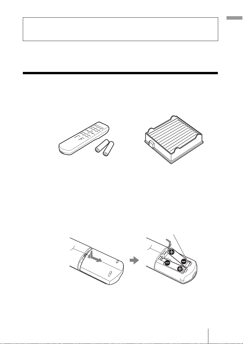
Unpacking
Check the carton to make sure it contains the following items:
Connections and Pre pa ra tions
• Remo te control (1)
• Size AA (R6) batteries (2)
• AC power cord (1 )
• CD-ROM (Applicatio n software and
Operating In structions) (V P L-HS51
only)
• Air filter (for replacement) (1)
• Operating Instructions (this manual) (1)
Inserting the batteries into the remote control
Insert the batteries E side first as shown in the illustration.
Inserting them forcibly or with t he polarit ies rev ers ed may caus e
a short circuit and may generate heat.
7Unpacking
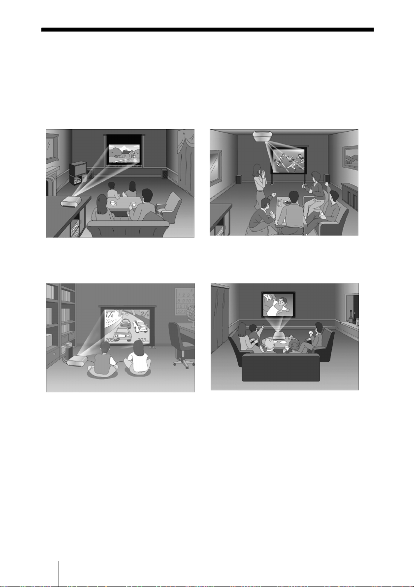
Step 1: Installing the Projector
The projector’s lens shift feature allows you to choose a variety of installation
locations for your projector. You can enjoy home entertainment with this
projector in the following situations.
Enjoying home theater
Watching sports, etc. with your
company
Enjoying video games on a large
screen
Viewing images shot by a digital video
camera on a large screen
8 Step 1: Installing the Projector
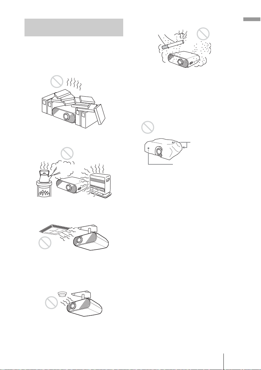
Before Setting Up the Projector
Do not place the projector in the following
situations, which may cause malfunction
or damage to the projector.
Poorly ventilated
Very dusty and extremely smoky
Connections and Pre pa ra tions
Make a special attention to the following
while using the projector.
Do not block the ventilation holes.
Highly heated and humid
Subject to direct cool or warm air
from an air-conditioner
Installing in such a location may cause
malfunction of the unit due to moisture
condensation or r is e in te mp e rature.
Near a heat or smoke sensor
Ventilation holes
(intake)
Ventilation holes
(exhaust)
Tip
For details on the location of the ventila tion
holes (intake or exhaust), see “Location o f
Controls” on pages61 to 63.
When installing the unit at altitudes
When using the projector at an altitude of 1,500
m or higher, set “High Altitude Mode” in the
Installation menu to “On.” (1 page 42)
Failing to set this mode when using the
projector at high altitudes could have adverse
effects, such a s r educing the relia bility of
certain components.
Malfunction of the sensor may be caused.
9Step 1: Installing the Projector
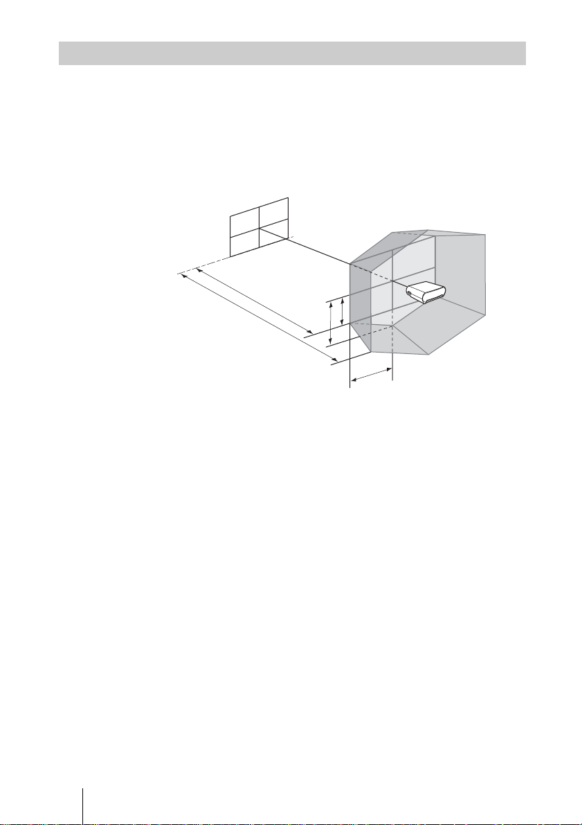
Installing the Projector and a Screen
The installation distance between the projector and a screen varies depending
on the size of the screen.
1 Determine the installation position of the projector and screen.
You can obtain a good quality picture if you position the projector with the
center of the lens within the areas indicated in the gray areas in the
illustration. Use the values a, b, c, d and e in the table on page 11 as a g uide.
Screen
a
b
a: Minimum projection distance between the screen and the center of the
projector’s l ens
b: Maximum projection distance between the screen and the center of the
projector’s l ens
c: Vertical distance between the center of the screen and the center of the
projector’s lens when using the maximum vertical lens shift feature*
d: Horizontal distance between the center of the screen and the center of
the projector’s lens when using the maximum horizontal lens shift
feature*
e: Maximum vertical distance between the center of the screen and the
center of the projector’s lens when using both the vertical and
horizontal lens shift features with the horizontal lens shift set to the
maximum value*
* The distances c, d and e indicated in the illustration show those in the lower
or left direction. The same distances i n t he upper or right direction are
appropriate fo r i n stallation.
e
c
d
For details on the lens shift feature, see “Step 3: Adjusting the Picture Size
and Position.” (1 page 17)
10 Step 1: Installing the Projector
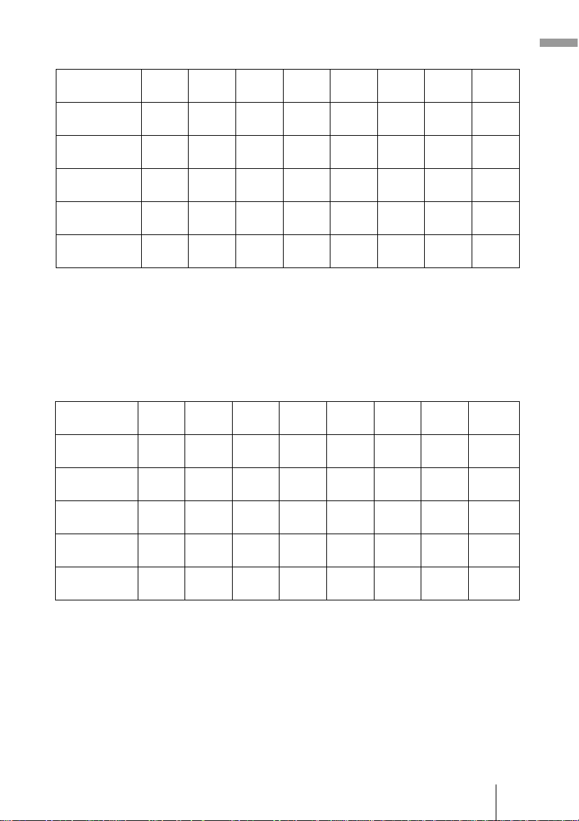
When using the 16:9 aspect ratio screen
Screen size
(inches)
a (minimum) 1170
b (maximum) 1790
c 498
d 443
e 249
40 60 80 100 120 150 180 200
1770
1
(46
/8)
(69 3/4)
2710
1
/2)
(70
(19
(17
(9
To calculate the installation measurements (SS: Screen Size)
a (minimum) = {(SS × 21.27/0.7227) – 35.160899} × 1.025
b (maximum) = {(SS × 33.9409273/0.7227) – 37.678872} × 0.975
c = (SS/0.7227 × 9)
d = (SS/0.7227 × 8)
e = (SS/0.7227 × 4.5)
(106 3/4)
747
5
/8)
(29 1/2)
664
1
/2)
(26 1/4)
374
7
/8)
(14 3/4)
When using the 4:3 aspect ratio screen
Screen size
(inches)
a (minimum) 1440
b (maximum) 2200
c610
d542
e305
40 60 80 100 120 150 180 200
2180
3
(56
/4)
(85 7/8)
3330
5
/8)
(86
(24
(21
(12
(131 1/8)
914
1
/8)
(36)
813
3
/8)
(32 1/8)
457
1
/8)
(18)
2380
(93 3/4)
3630
(143)
996
(39 1/4)
886
(35)
498
(19 5/8)
2920
(115)
4450
(175 1/4)
1219
(48)
1084
(42 3/4)
610
(24 1/8)
2980
(117 3/8)
4540
(178 7/8)
1245
(49 1/8)
1107
(43 5/8)
623
(24 5/8)
3660
(114 1/8)
5570
(219 3/8)
1524
(60)
1355
(53 3/8)
762
(30)
3580
(141)
5460
(215)
1494
(58 7/8)
1328
(52 3/8)
747
(29 1/2)
4390
(172 7/8)
6690
(263 1/2)
1829
(72 1/8)
1626
(64 1/8)
914
(36)
4490
(176 7/8)
6830
(269)
1868
(73 5/8)
1660
(65 3/8)
934
(36 7/8)
5500
(216 5/8)
8370
(329 5/8)
2286
(90 1/8)
2032
(80 1/16)
1143
(45)
Unit: mm (inches)
5390
(212 1/4)
8210
(323 3/8)
2241
(88 1/4)
1992
(78 1/2)
1121
(44 1/4)
Unit: mm (inches)
6610
(260 3/8)
10050
(395 3/4)
2743
(108 1/8)
2438
(96)
1372
(54 1/8)
6000
(236 1/4)
9120
(359 1/8)
2491
(98 1/8)
2214
(87 1/4)
1245
(49 1/8)
7350
(289 1/2)
11170
(439 7/8)
3048
(120
2709
(106 3/4)
1524
(60)
Connections and Pre pa ra tions
1
/16)
To calculate the installation measurements (SS: Screen Size)
a (minimum) = {(SS × 21.27/0.5906) – 35.160899} × 1.025
b (maximum) = {(SS × 33.9409273/0.5906) – 37.678872} × 0.975
c = (SS/0.5906 × 9)
d = (SS/0.5906 × 8)
e = (SS/0.5906 × 4.5)
11Step 1: Installing the Projector
2 Position the projector so that the lens is parallel to the screen.
Top view
Screen
3 Project an image on the screen and adjust the picture so that it
fits the screen. (1 page 17)
To project an image, connect video equipment to the projector. (1 page
13)
Note
When using a screen with an uneven surface, stripes pattern may rarely appear on the
screen dependin g on the distance between the screen and the pro je ctor or the zooming
magnifications. This is not a malfunction of the projector.
For installation of the projector on a ceiling, see “Ceiling Installation.” (1
page 58)
12 Step 1: Installing the Projector
Step 2: Connecting the Projector
When making connections, be sure to do the following:
• Turn off all equipment before making any connections.
• Use the proper cables for each connection.
• Insert the cable plugs properly; plugs that are not fully inserted often
generate noise. When pulling out a cable, be sure to pull it out from the plug,
not the cable itself.
• Refer to the operating instructions of the connected equipment.
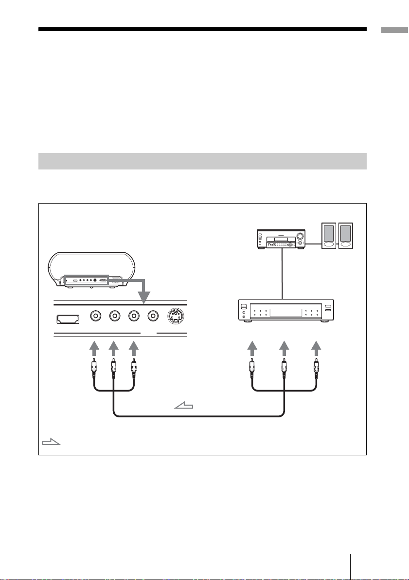
Connecting to a D VD Player/Recorder or Digital Tune r
To connect to a DVD player/recorder or digital tuner equipped with
component video connectors
Connections and Pre pa ra tions
AV amplifier
Rear of the projector
DVD player/recorder,
digital tune r , etc., with
component video
connectors
Y
PB/CB PR/CR VIDEOHDMI
PB/
Y
B
C
: Video signal flow
PR/C
Component video cable (not supplied)
INPUT
S VIDEO
R
Y
PB/
C
B
Tip
To connect the projector to a DVD player/recorder, digital tuner, etc. which is not
equipped with component video connectors, use the S video cable to connect to the Svideo output of the DVD player/r ecord er, dig ital t uner, e tc. I f the c onnected e quipment
is not equipped with the S-video output connector, use the video cable to connect to the
video output jack on t he equipment.
Speakers
PR/C
R
13Step 2: Connecting the Projector
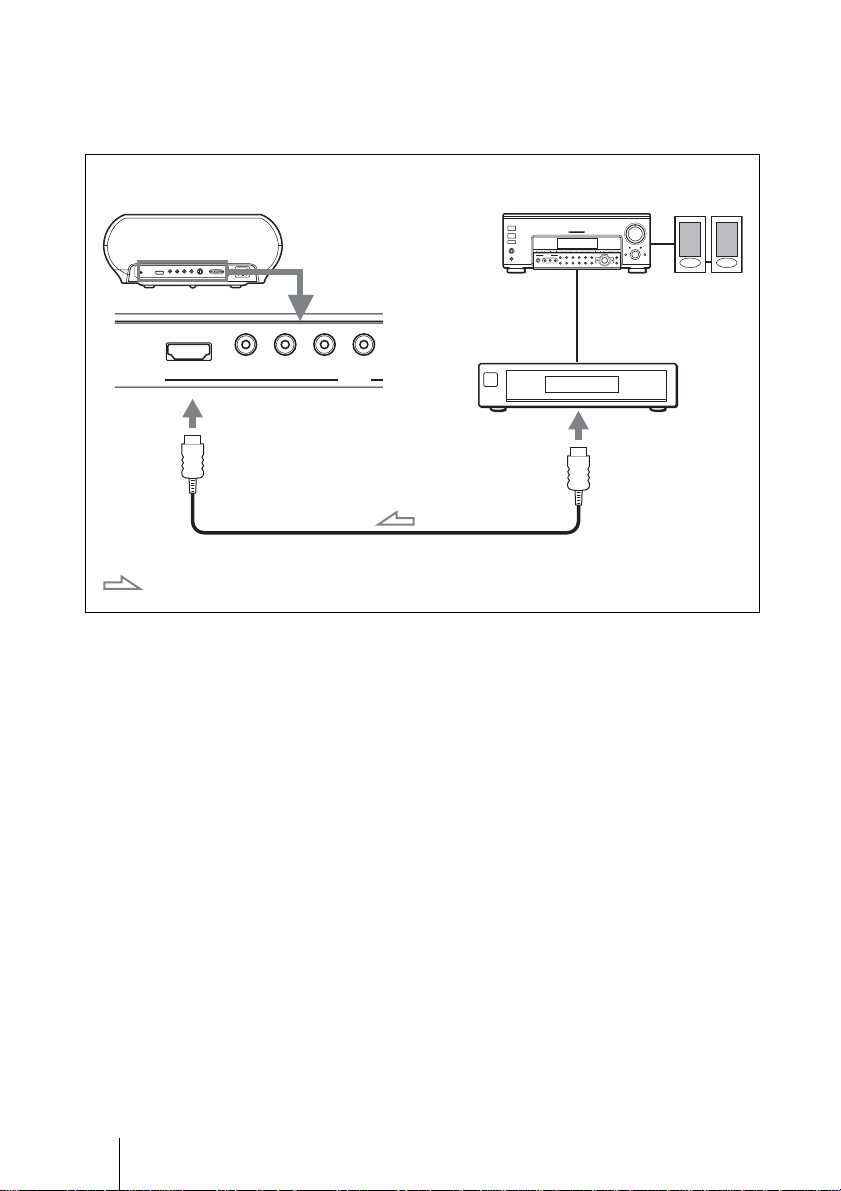
To connect to a DVD player/recorder equipped with HDMI
output
You can enjoy better picture quality by connecting a DVD player/recorder
equipped with HDMI output to the HDMI input of the projector.
Rear of the projector
: Video signal flow
AV amplifier
DVD player/recorder,
etc., with the HDMI
output
Y PB/CB PR/CR VIDEOHDMI
INPUT
to HDMI output
HDMI cable ( not supplied)
Speakers
............................................................................................................................................................
HDMI, HDMI logo and High-Definition Multimedia Interface are tra demar ks or regis tered
trademarks of HDMI Li censing LLC.
14 Step 2: Connecting the Projector
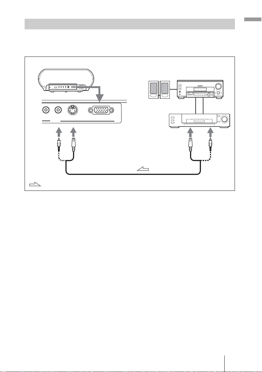
Connecting to Video Equipment
You can connect a DVD player/recorder which is not equipped with
component video connectors, hard disk video recorder, VCR or laser disk
player. See also the instruction manual of each equipment.
Rear of the projector
PR/CR VIDEO
INPUT
S VIDEO
INPUT A
Speakers
Video equipment
to S video or
video output
Connections and Pre pa ra tions
AV amplifier
: Video signal flow
S video or video cable (not supplied)
Tip
If you do not know to which connector you should connect the cable, S VIDEO (S video
connector) or VIDEO (video connector), connect it to S VIDEO to enjoy better picture
quality.
If the equipment to be connected has no S video connector, connect the cable to the
video output.
15Step 2: Connecting the Projector
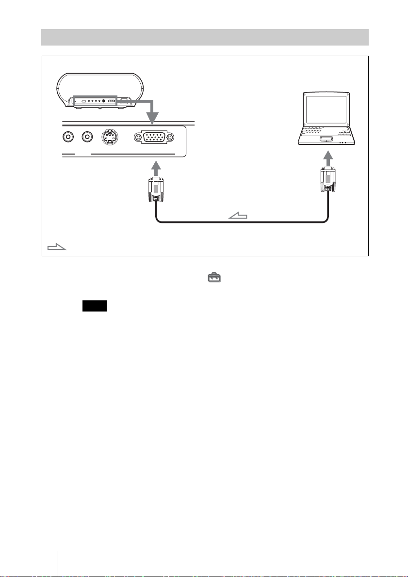
Connecting to a Compute r
Rear of the projector
Computer
PR/CR VIDEO
: Video signal flow
INPUT
S VIDEO
INPUT A
to monitor output
HD D-sub 15-pin cable (not supplied)
Tip
Set “Input A Signal Sel.” in the Setup menu to “Auto” or “Computer.” If the input
signal does not appear properly, set it to “C om puter.”
Note
If you set your computer, such as a notebook type, to output the s ig nal to both your
computer’s display and an external moni tor, the picture of the e xternal monitor may not
appear properly. Set your computer to output the signal to only the external monitor.
For details, refer to the computer’s operating in structions supplied with y o ur c omp ut er.
16 Step 2: Connecting the Projector
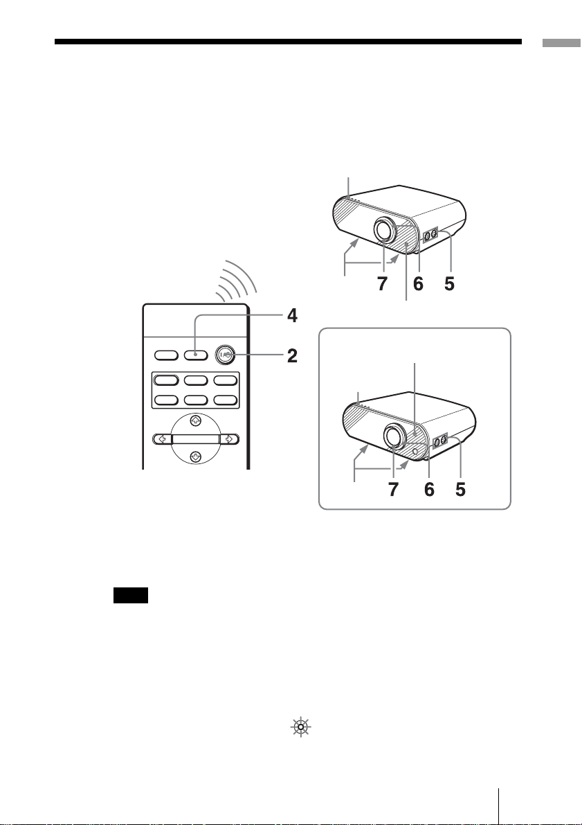
Step 3: Adjusting the Picture Size and
Y
Position
Project an image on the screen and then adjust the picture position.
VPL-HS50
ON/STANDBY indicator
Adjusters
Remote control detector
Connections and Pre pa ra tions
VPL-HS51
DYNAMIC
INPUTLIGHT
STANDARD
PICTURE MODE
USER 2
ENTER
CINEMA
USER 3USER 1
ON/STANDBY
indicator
Adjusters
Remote control detector
Tip
The I/1 (on/standby), INPUT, MENU, and M/m/</,/ENTER (joystick) but tons on
the side panel of the pr oj ector function the same as those on the remot e control.
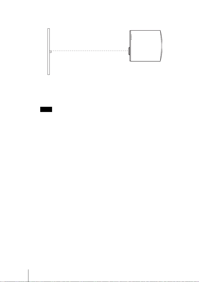
Note
Depending on the installatio n location of the projector, you may not control it with the
remote control. In this case, point the remote control to the screen instead of the
projector.
1 Plug the AC power cord into a wall outlet.
The ON/STANDBY indicator lights in red and the projector goes into
standby mode.
Lights in red.
ON/
STANDB
17Step 3: Adjusting the Picture Size and Position
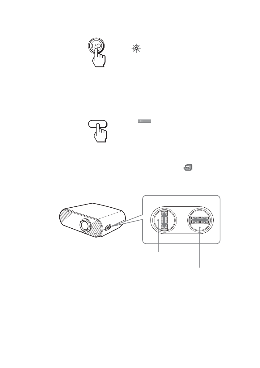
2 Press the I/1 (on/standby) switch to turn on the projector.
Y
The ON/STANDBY indicator lights in green.
Lights in green.
ON/
STANDB
3 Turn on the equipment connected to the projector.
Refer to the operating instructions of the connected equipment.
4 Press INPUT to project the picture on the screen.
Each time you press the button, the input indication changes. (1 page 24)
INPUT
Tip
When “Auto Input Search” is set to “On” in the Function menu, the channel
of the signal input is automatically displayed.
Video
5 Move both LENS SHIFT dials to adjust the picture position.
LENS SHIFT
To adjust the vertical
position
To adjust the horizontal position
18 Step 3: Adjusting the Picture Size and Position
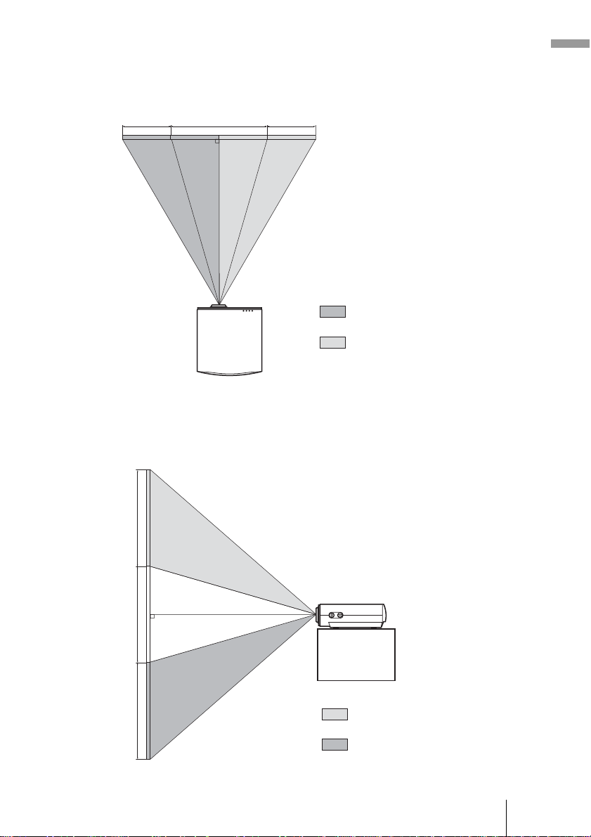
To adjust the horizontal position
Turn the LENS SHIFT dial right or left.
The picture moves right or left by a maximum of half of the screen size from
the center of the lens.
1
/2H
1H
1
/2H
Top view
: Picture position when moving the
picture to the left at maximum
: Picture position when moving the
picture to the right at maximum
To adjust the vertical position
Turn the LENS SHIFT dial up or down.
The picture moves up or down by a maximum of the screen size from the
center of the lens.
Connections and Pre pa ra tions
1V
1V
1V
Side view
: Picture position when moving the
picture upward at maximum
: Picture position when moving the
picture downward at maximum
19Step 3: Adjusting the Picture Size and Position
Note
When you use the horizontal and vertical lens shift features at the same time, you
can move the pictu re vertically by a maxi m um of half of the scre en size.
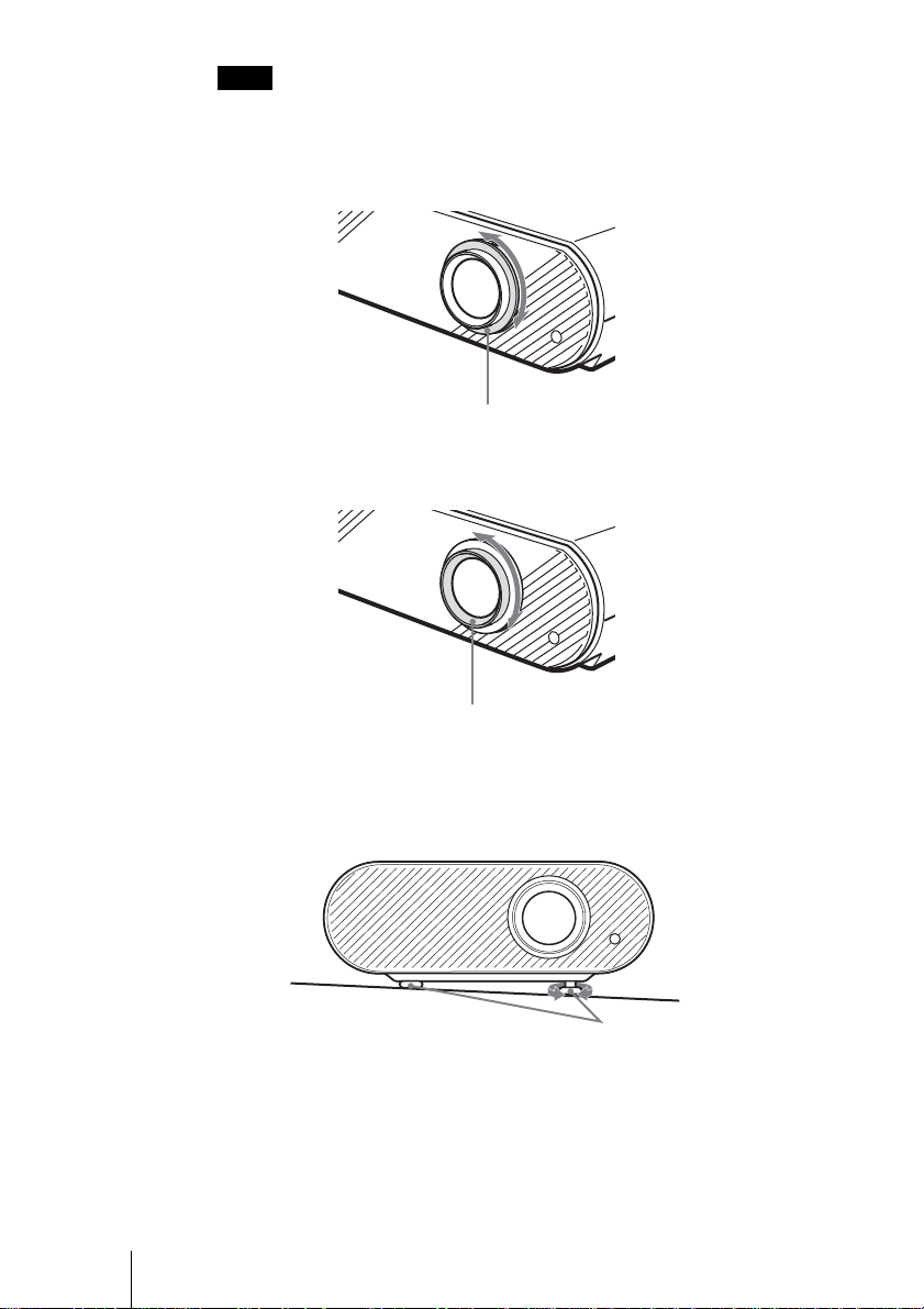
6 Adjust the picture size using the zoom ring.
Zoom ring
7 Adjust the focus using the focus ring.
Focus ring
To adjust the tilt of the installation surface
If the projector is installed on an uneven surface, use the adjusters to keep the
projector level.
20 Step 3: Adjusting the Picture Size and Position
Turn to adjust.
Adjusters
Step 4: Selecting the Menu Language
You can select one of fifteen languages for displaying the menu and other onscreen displays. The factory default setting is English.
Connections and Pre pa ra tions
DYNAMIC
PICTURE MODE
WIDE MODE
REAL COLOR PROCESSING
INPUTLIGHT
STANDARD
USER 2
ENTER
ADJ PIC
RCP
CINEMA
USER 3USER 1
MENUAPA
RESET
2
4-6
3
Tip
You can operate the menu using the M/m/</, (arrow) buttons on the side panel of
the projector inst ead of the M/m/</,/ENTER buttons on the remote control.
1 Plug the AC power cord into a wall outlet.
The ON/STANDBY indicator lights in red and the projector goes into
standby mode.
2 Press the I/1 (on/standby) switch to turn on the projector.
The ON/STANDBY indicator lights in green.
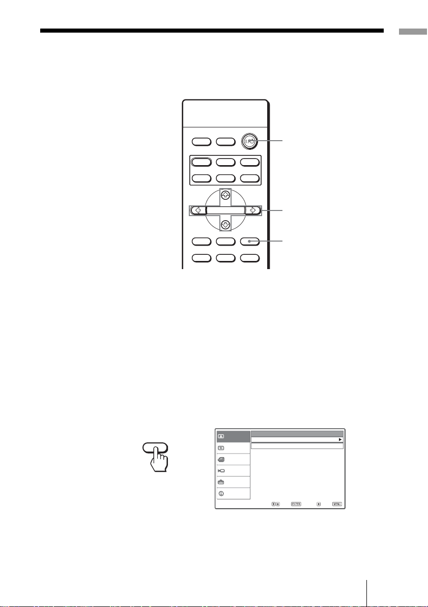
3 Press MENU.
The menu appears.
Cinema
Off
MENU
Picture
Signal
Function
Installation
Setup
Information
Picture Mode :
Adjust Picture
RCP :
Sel : Set : Back : Exit :
21Step 4: Selecting the Menu Language
 Loading...