

Page 1
Video Projector VPL-HS20
4-099-551-11(1)
Video Projector
Operating Instructions __________________________________
Mode d’emploi _________________________________________
Manual de instrucciones _________________________________
GB
FR
ES
VPL-HS20
© 2003 Sony Corporation
Page 2
WARNING
To prevent fire or shock hazard, do not expose
the unit to rain or moisture.
To avoid electrical shock, do not open the
cabinet. Ref er servic ing to qual ified pers onnel
only.
This symbol is intended to alert the user to
the presence of uninsulated "dangerous
voltage" within the product's enclosure
that may be of sufficient magnitude to
constitute a risk of electric shock to
persons.
This equipment has been tested and found to comply
with the limits for a Class B digital device, pursuant to
Part 15 of the FCC Rules. These limits are designed to
provide reasonable protection against harmful
interference in a residential installation. This equipment
generates, uses, and can radiate radio frequency energy
and, if not installed and used in accordance with the
instructions, may cause harmful interference to radio
communications. However, there is no guarantee that
interferen ce wi ll n ot occu r in a par tic ular ins tal la tion. I f
this equipment doe s cause harmful in terf erenc e to radio
or television reception, which can be determined by
turning the equipment of f and on, the user is encouraged
to try to correct the interference by one or more of the
following measures:
- Reorient or relocate the receiving antenna.
- Increase the separation between the equipment and
receiver.
- Connect the equipment into an outle t on a circuit
different from that to which the receiver is connected.
- Consult the dealer or an experienced radio/TV
technician for help.
Y ou are cautioned th at any changes or modifi cations not
expressly approved in this manual could void your
authority to operate this equipment.
This symbol is intended to alert the user to
the presence of important operating and
maintenance (servicing) instructions in
the literature accompanying the
appliance.
For the customers in the USA
If you have any questions about this product, you may
contact:
Sony Electronics Inc.
Attn: Business Information Center (BIC)
12451 Gateway Boulevard
Ft. Myers, Florida 33913
Telephone No.: 800-686-7669
The number below is for FCC related matters only.
Declaration of Conformity
Trade Name: SONY
Model No.: VPL-HS20
Responsible Party: Sony Electronics Inc.
Address: 680 Kinderkamack Road, Oradell
NJ 07649 U.S.A.
Telephone No.: 201-930-6972
This device complies with Part 15 of the FCC Rules.
Operation is subject to the following two conditions: (1)
This device may not cause harmful interference, and (2)
this device must accept any interference received,
including interference that may cause undesired
operation.
For the customers in Canada
This Class B digital apparatus complies with Canadian
ICES-003.
Voor de klanten in Nederland
Dit apparaat bev a t een vast ingebouwde batterij die niet
vervangen h oeft te wo rden tijdens de lev ensduur v an het
apparaat.
Raadpleeg uw leverancier indien de batterij toch
vervangen moet worden. De batterij mag alleen
vervangen worden door vakbekwaam servicepersoneel.
Gooi de batterij niet weg maar lever deze in als klein
chemisch afval (KCA).
Lever het apparaat aan het einde van de levensduur in
voor recycling, de batterij zal dan op correcte wijze
verwerkt worden.
The socket-outlet should be installed near the
equipment and be easily accessible.
GB
2
Page 3

Table of Contents
Precautions .............................................5
Adjusting Picture Quality of a Signal from the
Computer ......................................................... 36
Using a “Memory Stick”
About a “Memory Stick” .......................37
Preparing for Viewing the Picture Files
Stored in a “Memory Stick” ..................40
Inserting a “Memory Stick” .............................40
Displaying the Desired Pictures in
Connections and Preparations
Unpacking ...............................................6
Step 1: Installing the Projector ..............7
Before Setting Up the Projector .........................7
Using the Optional Conversion Lens .................8
Installing the Projector and a Screen
— Floor Installation ...........................................9
Installing the Projector and a Screen
— Ceiling Installation ......................................11
Step 2:
Connecting the Projector .....................13
Step 3: Adjusting the Picture Size and
Position ..................................................19
Step 4:
Selecting the Menu Language .............23
Digital Camera Mode .......................................41
Viewing the Pictures .............................44
Viewing the Pictures in Sequence
— Slide Show ..................................................44
Displaying a Picture on the Full Screen
— Full Screen ..................................................45
Playing Movie Pictures ....................................46
Selecting the Folder Containing the Desired
Picture .............................................................. 48
Rotating a Still Picture ..........................49
Protecting an Important Picture ..........50
Projecting a Selected Picture When the
Power Is Turned On — Startup ............51
Registering a Still Picture as the Startup
Picture .............................................................. 51
Setting the Startup Picture ...............................52
Deleting a Picture ..................................53
Projecting
Projecting the Picture on the Screen ..25
Selecting the Wide Screen Mode ........27
Selecting the Picture Viewing Mode ...29
Using the Menus
Operation through the Menus .............30
Menu Lists .............................................32
Menu Configurations ........................................32
Menu Items .......................................................32
About the Preset Memory No. ..........................36
Sorting the Pictures ..............................55
Displaying Either of the Still Pictures
or Movie Pictures ..................................56
Displaying the “Memory Stick”
Information ............................................57
Initializing a “Memory Stick”
— Format ...............................................58
Others
Troubleshooting ....................................... 59
Replacing the Lamp .................................62
Replacing the Air Filter ............................63
3
GB
Page 4

Specifications ..........................................64
Location of Controls ................................74
Front ................................................................. 74
Rear ..................................................................75
Bottom .............................................................. 76
Remote Control ................................................77
Index .........................................................76
GB
4
Page 5

Precautions
On safety
• Check that the operating voltage of your unit is
identical with the voltage of your local power
supply.
• Should any liquid or solid object fall into the
cabinet, unplug the unit and have it checked by
qualified personnel before operating it further.
• Unplug the unit from the wa ll outlet if it i s not to be
used for several days.
• T o disconnect the co rd, pull it out by the plug. Never
pull the cord itself.
• The wall outlet should be near the unit and easily
accessible.
• The unit is not disconnected to the AC p ower source
(mains) as long as it i s conne cted t o t he w all ou tlet ,
even if the unit its elf has been turned off.
• Do not loo k into the lens while the lam p is on.
• Do not place your hand or objects near the
ventilation holes. The air coming out is hot.
On preventing internal heat build-up
After you turn off the power with the I/1 (on/standby)
switch, do not disconne ct the unit f rom the wall o utlet
while the cooling fan is still running.
Caution
The projector is equipped with ventilation holes
(intake) and v entilatio n holes (exh aust). Do not block
or place anything near these holes, or internal heat
build-up may occur, causing picture degradation or
damage to the projector.
On repacking
Save the original shipping carton and packing
material; they will come in handy if you eve r have to
ship your unit. F or maximum prote ction, repac k your
unit as it was originally packed at the factory.
Precautions
5
GB
Page 6
Connections
and
Preparations
This section describes how to install the
projector and screen, how to connect the
equipment from which you want to project
the picture, etc.
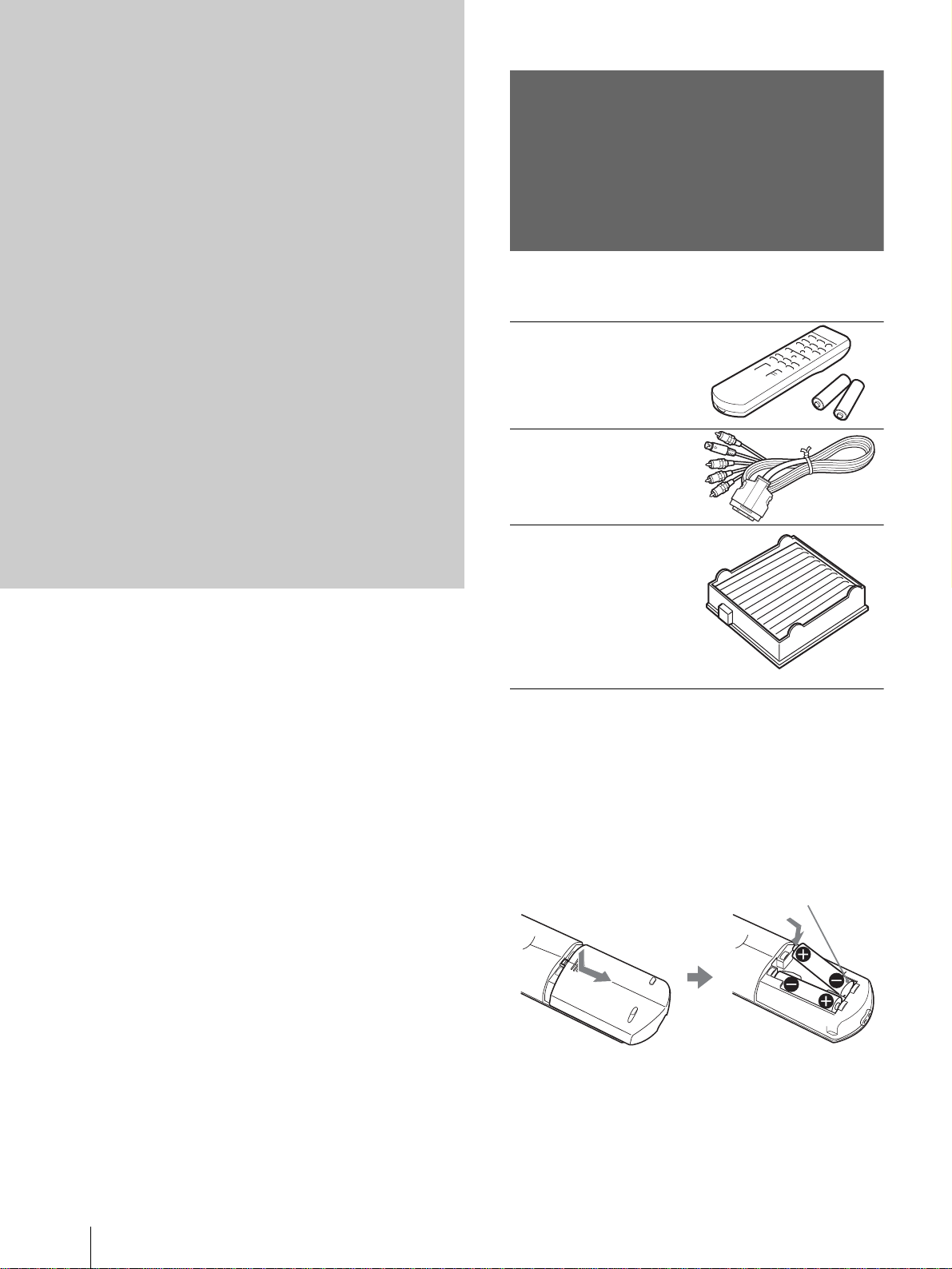
Unpacking
Check the carton to make sure it contains the
following items:
Remote control (1),
Size AA (R6)
batteries (2)
Signal interface
cable (1)
Air filter (for
replacement) (1)
AC power cord (1)
Operating Instructions (this manual) (1)
Inserting the batteries into the remote
control
Insert the batteries E side first as sho wn
in the illustration.
Inserting them forcibly or with the
polarities reversed may cause a short
circuit and may generate heat.
GB
6
Unpacking
Page 7
Step 1: Installing
the Projector
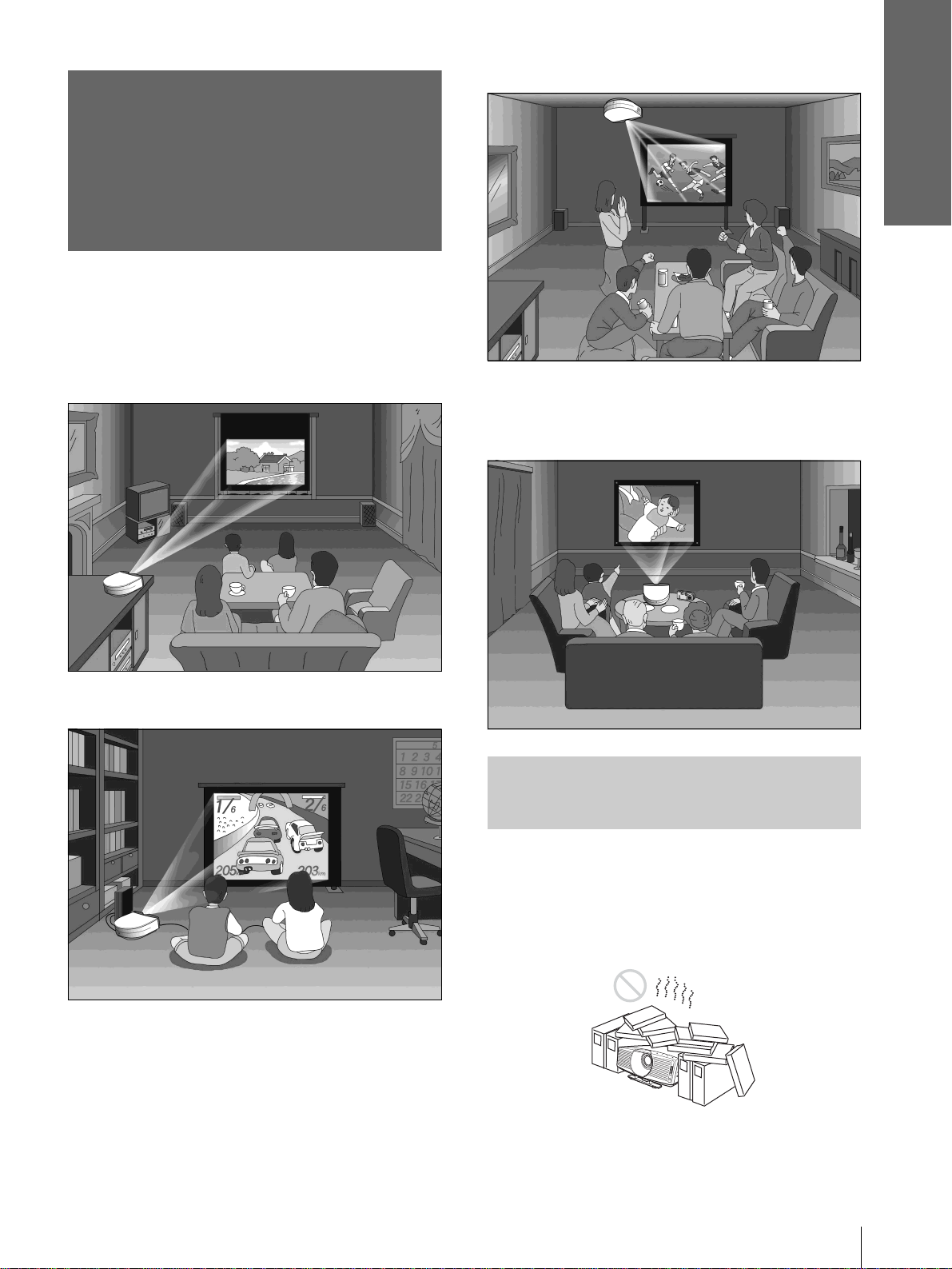
You can obtain good picture quality even when you
project the picture from the side of the screen (“Side
Shot”) (1 page 10). You can enjoy home
entertainment with this projec tor in v arious situ ations.
Connections and
Preparations
Watching sports, etc. with your company
Enjoying home theater
Enjoying video games on a large screen
Viewing images, recorded by a digital
camera and stored in the “Memory Stic k,” on
a large screen
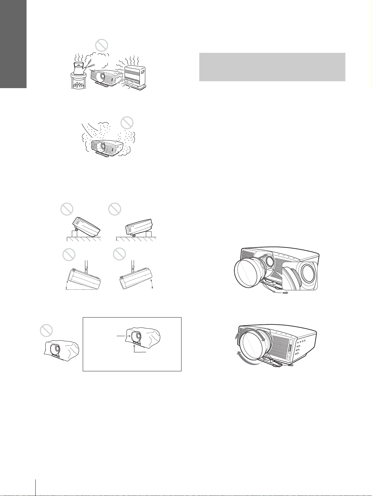
Before Setting Up the
Projector
Do not place the projecto r in the follo wing sit uations,
which may cause malfunction or damage to the
projector.
Poorly ventilated
Step 1: Installing the Projector
7
GB
Page 8
Connections and
Preparations
Highly heated and humid
Very dusty and ext remely smoky
Do not use the projector under the following
conditions:
Tilting the unit extremely
effects, such as reducing the reliability of certain
components.
Using the Optional
Conversion Lens
You can ins tall the following two types of lenses
(optional) on the projector. For projection distances
when inst alling the Conversion Lens, see page 67.
• VPLL-CT10 Long Focused Conversion Lens
• VPLL-CW10 Short Focused Conversion Lens
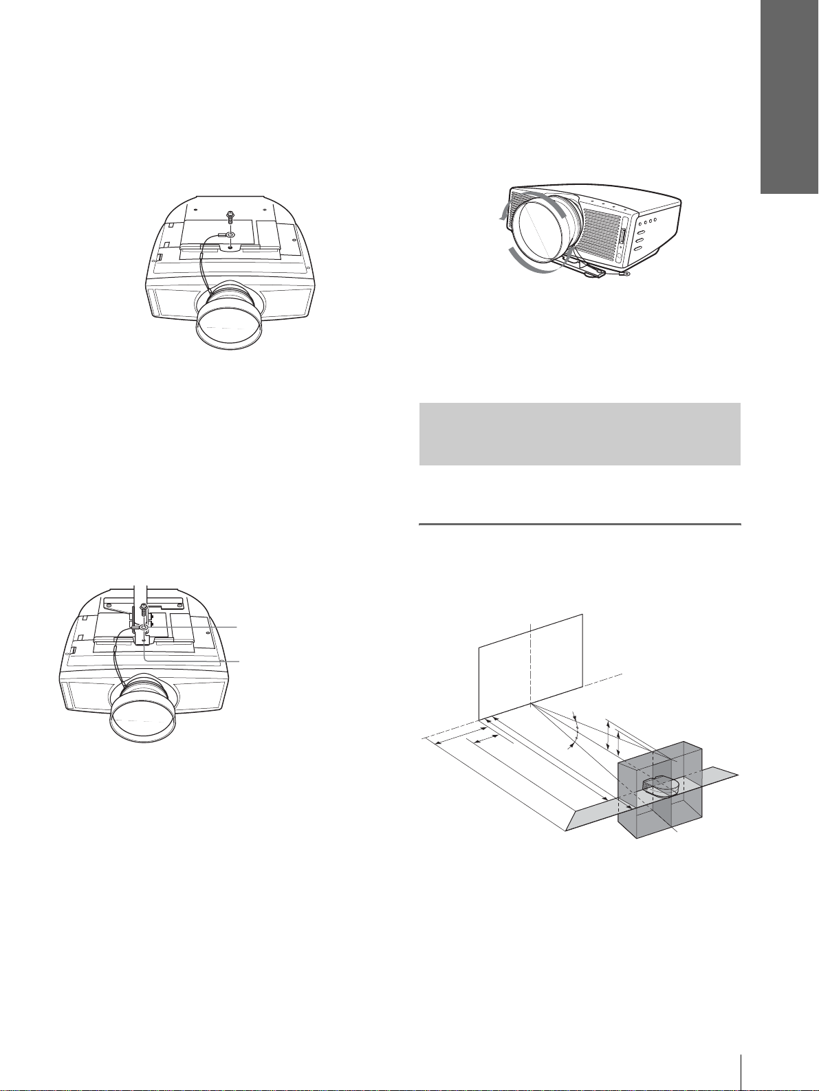
Follow th e steps belo w to i nstall the Conversion Lens.
For details on installing the Lens, re fer also to the
installation manual supplied with the Lens.
1 Turn off the power and disconnect the
power cord.
2 Remove the lens hood from the pr ojector’ s
lens, and remove the lens cap from the
Conversion Lens.
15˚
15˚
Blocking the ventilation holes
Ventilation
holes
(exhaust)
Tip
For further details on th e loc ation of th e ventilation holes (intake
or exhaust), see “Location of Controls” o n pages 74 to 76.
Ventilation
holes
(intake)
Note
Installing the unit at altitudes
When using the projector at an al tit ude of 1,50 0 m or
higher, turn on high altitude mode in the INSTALL
SETTING menu. Failing to set this mode when using
the projector at high altitudes could have adverse
3 Align the screw of the Conversion Lens
with the thread around the lens of the
projector as illustrated below.
4 Turn the Conversion Lens clockwise until
you hear it click.
Note
If the Conversion Lens is hard to turn, turn it slightly
counterclockwise first, then turn it clockwise.
5 Place a thick cloth (e.g., a cushion)
beneath the projector. Place the projector
face down.
Note
The optional Conversion Lens projects from the top of the
projector when the Lens is instal l ed on the projector. Before
installation, place a cloth of adequate thickness beneath the
GB
Step 1: Installing the Projector
8
Page 9
Connections and
Preparations
projector to keep the Lens from contact with the floor or a
desk top. Otherwise, the Lens may malfunction if it receives
too much pressure from the weight of the projector.
6 Fasten the end of the safety wire of the
Conversion Lens to the bottom of the
projector using the screw supplied with
the Conversion Lens (M5×8, with washer).
Note
Be sure to fasten the end of the safety wire of t he Le ns to the
bottom of the projector.
When installing the projector on the ceiling
Be sure to fasten the end of the safety wire of the Lens
to both the projector and the PSS-610 Projector
Suspension Support in ste p 6, as illustrated below. In
this case, use the screw (M5×12, with washer)
supplied w ith the PSS-610.
First, place the PSS-610 ( 1 ) on the projector, then
place the safety wire ( 2 ) on the PSS-610.
To remove the installed Conversion Lens
1 Remove the end of the safety wire of the
installed Lens from the bottom of the
projector by removing the screw.
2 Turn the installed Lens counterclockwise
until it can be removed.
Notes
• Be sure not to drop the uninstalled Conversion Lens.
• When you adjust picture distortion using “V Keystone” or
“Side Shot” in the INSTALL SETTING menu with the
optional Conversion Lens attached to the projector, the
aspect ratio of the original picture may not be correctly
displayed.
Installing the Projector and a
Screen — Floor Installation
The installation distance between the projector and
screen varies depending on the size of the screen.
1
Determine the ins tallation
position of the projector and
screen.
End of safety wire
2
PSS-610 Projector
1
Suspension
Support
WARNING
Be sure to use the screw (M5×12 with washer) supplied with the
PSS-610. Never use the screw supplied with the Conversion Lens.
If you use the screw supplied with the Lens, the Lens may fall
from the projector and may cause injury.
Notes on installation of the optional Conversion Lens
• The Lens scratches easily, so when handling it, always place it
gently on a stable and level surface in a horizontal position.
• Be sure not to bump the Lens on the surface of the lens of the
projector.
• Avoid touching the Lens surface.
Screen
d
c
a
12˚
f
f
12˚
b
e
Projector
a: Minimum projection distance between the
screen and the center of the projector’s lens
when you place the projector on the side
(“Side Shot”), or when you place the
projector with the center of the screen and the
center of the lens aligned.
Step 1: Installing the Projector
9
GB
Page 10
Connections and
Preparations
b: Maximum projection distance between the
screen and the center of the projector’s lens
when you place the projector on the side, or
when you place the projector with the center
of the screen and the center of the lens
aligned
c: Maximum horizontal distance between the
right/left end of the screen and the center of
the projector’s lens when the projector is
placed on the side (when you use projection
distance a)
d: Maximum horizontal distance between the
right/left end of the screen and the center of
the lens when the projector is placed on the
side (when you use projection distance b)
e: Maximum vert ical distance from the bo t tom
of the screen to the center of the projector’s
lens when you place the pr ojector on the side
(when you use projection distance a)
f: Maxi mum vertical distance from the bottom
of the screen to the center of the projector’s
lens when you place the pr ojector on the side
(when you use projection distance b)
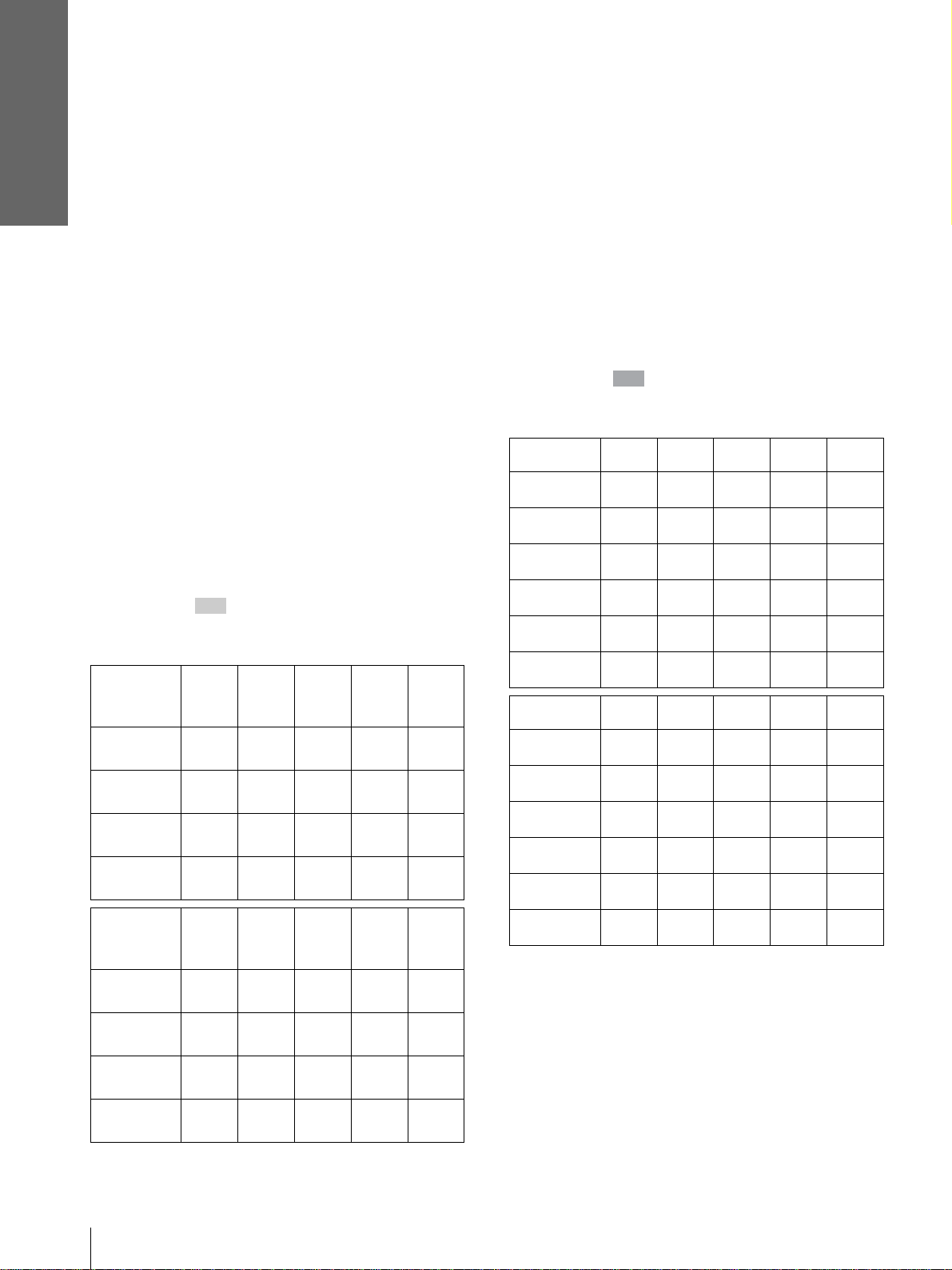
When projecting using “Side Shot”
adjustment only (1 page 20)
Position t he projector w ith the lens end within
the area in the illust ration, by using the
values a, b, c and d in the table belo w as a guide.
Unit: m (feet)
Screen
size
(inches)
a
b
c
d
Screen
size
(inches)
a
b
c
d
40 60 80 100 120
1.6
(5.2)
1.8
(5.9)
0.2
(0.7)
0.3
(1.0)
150 180 200 250 300
6.0
(19.7)
7.0
(23.0)
0.7
(2.3)
1.1
(3.6)
2.4
(7.9)
2.8
(9.2)
0.3
(1.0)
0.4
(1.3)
7.3
(24.0)
8.4
(27.6)
0.8
(2.6)
1.3
(4.3)
3.2
(10.5)
3.7
(12.1)
0.3
(1.0)
0.6
(2.0)
8.1
(26.6)
9.4
(30.8)
0.9
(3.0)
1.5
(4.9)
4.0
(13.1)
4.7
(15.4)
0.4
(1.3)
0.7
(2.3)
10.1
(33.1)
11.7
(38.4)
1.1
(3.6)
1.9
(6.2)
4.8
(15.7)
5.6
(18.4)
0.5
(1.6)
0.9
(3.0)
12.1
(39.7)
14.1
(46.3)
1.4
(4.6)
2.2
(7.2)
Tip
The tables show the distances when projecting the 15 kHz
RGB/component, progressive component, DTV (480i/
480p/575i/575p), composite video and Y/C v ide o sig na l s.
Distances used for projecting a 1080i/720p format signal,
computer’s signal and data stored in the “Memory Stick”
are shown on page 66.
Note
If you project the pictur e using “Side Shot” only ,
set “V Keystone” in the INSTALL SETTING
menu to “Manual,” and adjust the level to “0.”
When projecting using both “Side Shot ”
and “V Keystone” ad justments (1 page
21)
Position the projector with the lens end within
the area in the illustration, by using the
values a to f in the table below as a guide.
Unit: m (feet)
Screen size
(inches)
a
b
c
d
e
f
Screen size
(inches)
a
b
c
d
e
f
Tip
The tables show the distances when projecting the 15 kHz
RGB/component, progressive component, DTV (480i/
480p/575i/575p), composite video and Y/C v ide o sig na l s.
Distances used for projecting a 1080i/720p format signal,
computer’s signal and data stored in the “Memory Stick”
are shown on page 66.
Note
When projecting with the optional Conversion Lens
attached, the valu es a, b, e and f are slightly different from
those in the table.
40 60 80 100 120
1.6
(5.2)
1.8
(5.9)
–0.1
(–0.3)
0
(0.0)0(0.0)0(0.0)0(0.0)0(0.0)
0.3
(1.0)
0.4
(1.6)
150 180 200 250 300
6.0
(19.7)
7.0
(23.0)
–0.3
(–1.0)
–0.1
(–0.3)
1.3
(4.3)
1.5
(4.9)
2.4
(7.9)
2.8
(9.2)
–0.1
(–0.3)
0.5
(2.0)
0.6
(2.0)
7.3
(24.0)
8.4
(27.6)
–0.4
(–1.3)
–0.1
(–0.3)
1.5
(4.9)
1.8
(5.9)
3.2
(10.5)
3.7
(12.1)
–0.2
(–0.6)
0.7
(2.3)
0.8
(2.6)
8.1
(26.6)
9.4
(30.8)
–0.4
(–1.3)
–0.1
(–0.3)
1.7
(5.6)
1.9
(6.2)
4.0
(13.1)
4.7
(15.4)
–0.2
(–0.6)
0.8
(2.6)
1.0
(3.3)
10.1
(33.1)
11.7
(38.4)
–0.5
(–1.6)
–0.1
(–0.3)
2.1
(6.9)
2.4
(7.9)
4.8
(15.7)
5.6
(18.4)
–0.3
(–1.0)
1.0
(3.3)
1.2
(3.9)
12.1
(39.7)
14.1
(46.3)
–0.6
(–1.6)
–0.1
(–0.3)
2.5
(8.2)
2.9
(9.5)
GB
10
Step 1: Installing the Projector
Page 11
When projecting from the center (1
page 22)
You can change the projection angle using the
adjuster. (1 page 20)
Position the projector with the lens end within
the area in the illustration page 9, by using
the values a and b in the table belo w as a gu ide.
When using the 16:9 aspect ratio screen
Unit: m (feet)
Screen
size
(inches)
a
b
Screen
size
(inches)
a
b
40 60 80 100 120
1.5
(4.9)
1.8
(5.9)
150 180 200 250 300
5.8
(19.0)
7.0
(23.0)
2.3
(7.5)
2.8
(9.2)
7.0
(23.0)
8.4
(27.6)
3.1
(10.2)
3.7
(12.1)
7.8
(25.6)
9.4
(30.8)
3.9
(12.8)
4.7
(15.4)
9.7
(31.8)
11.7
(38.4)
4.6
(15.1)
5.6
(18.4)
11.7
(38.4)
14.1
(46.3)
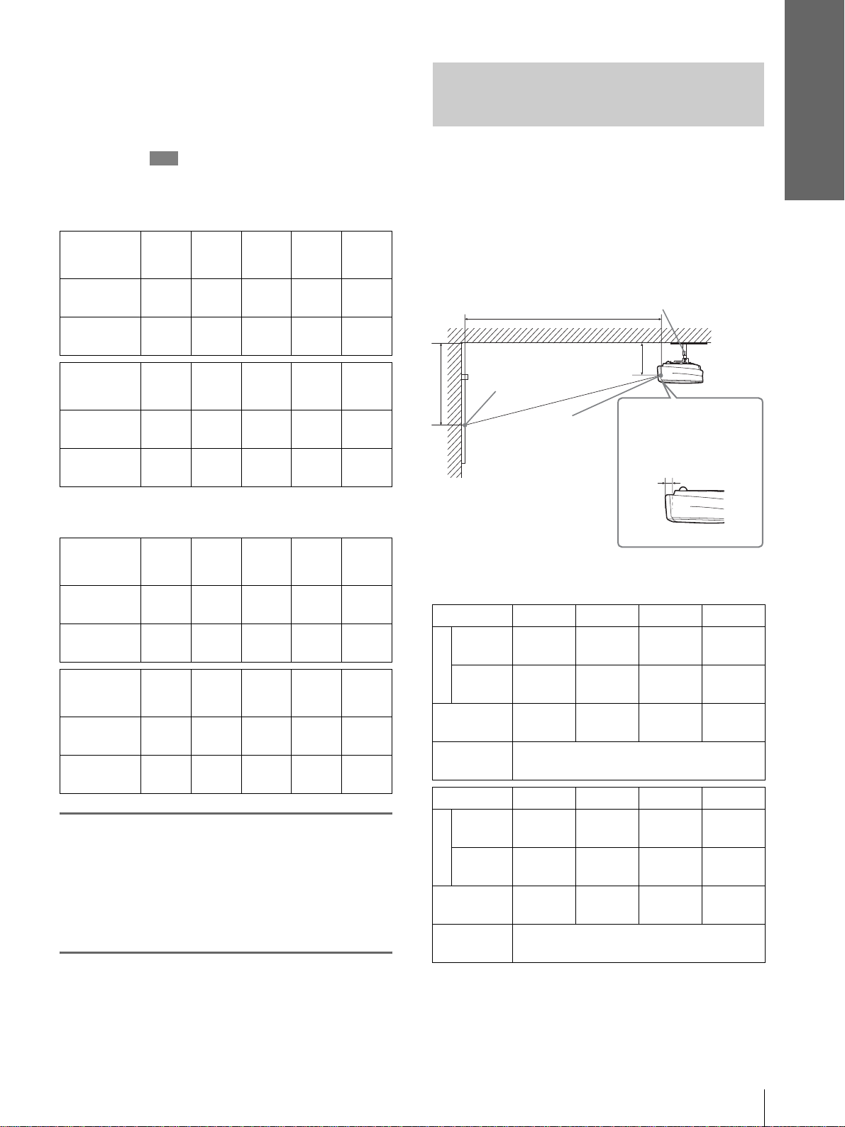
Installing the Projector and a
Screen — Ceiling In stallation
Use the PSS-610 Projector Su spension Suppor t when
you install the projector on a ceiling.
a: Distance between the center of the lens and the
screen
b: Distance between the ceiling and the center of the
lens
x: Distance between the ceiling and the center of the
screen
PSS-610 Projector Suspension
Support (not supplied)
a
Ceiling
b
Distance from the
front of the cabinet
and the center of the
lens
61.5 mm (21/2 inches)
x
Center of the
screen
Center of
the lens
Connections and
Preparations
When using the 4:3 aspect ratio screen
Unit: m (feet)
Screen
size
(inches)
Minimum
Maximun
Screen
size
(inches)
Minimum
Maximun
2
Project an image on the screen
40 60 80 100 120
/2)
/8)
1
/2)
3
/4)
2.8
(109 7/8)
3.4
(132 3/4)
8.5
(334 3/8)
10.2
(402 1/8)
1.8
1
(72
2.2
7
(87
150 180 200 250 300
7.1
(278
8.5
(334
3.7
(147 3/8)
4.5
(177 5/8)
9.4
(371 3/4)
11.4
(447)
4.7
(184 3/4)
5.7
(222 1/2)
11.8
(465 1/2)
14.2
(559 1/8)
5.6
(222 1/8)
6.8
(267 3/8)
14.2
(558 3/4)
17.1
(611 3/4)
and adjust the picture so that it
fits the screen. (1 page 19)
T o project an image, conne ct video equipment to
the projector. (1 page 13)
Note
When using a screen with an uneven surface, stripes pattern may
rarely appear on the screen depending on the distance between the
screen and the projector or the zooming magnifications. This is
not a malfunction of the projector.
Standard lens
When using the 16:9 aspect ratio screen
Unit: mm (inches)
SS (inches) 40 60 80 100
/4)
/4)
3
/4)
2290
(90 1/4)
2760
(108 3/4)
b+377
7
(b+14
5810
(228 7/8)
6990
(275 1/4)
b+924
(b+37 1/8)
Minimum
a
Maximum
x
b
SS (inches) 120 150 180 200
Minimum
a
Maximum
x
b
1510
1
/2)
(59
1820
3
(71
/4)
b+251
(b+10)
When using the PSS-610, adjustable with
243/268/293/343/368/393 mm
4640
3
(182
5580
3
(219
b+753
(b+29
When using the PSS-610, adjustable with
243/268/293/343/368/393 mm
/8)
3070
(121)
3700
(145 3/4)
b+502
(b+19 7/8)
6990
(275 1/4)
8400
(330 3/4)
b+1130
(b+44 1/2)
3850
(151 5/8)
4640
(182 3/4)
b+628
(b+24 3/4)
7770
(306)
9340
(367 7/8)
b+1255
(b+49 1/2)
Step 1: Installing the Projector
11
GB
Page 12
Connections and
Preparations
SS (inches) 250 300
Minimum
a
Maximum
x
b
9730
1
(383
/8)
11690
3
(460
/8)
b+1569
7
(b+61
/8)
When using the PSS-610, adjustable with
243/268/293/343/368/393 mm
11680
(460 3/8)
14040
(552 7/8)
b+1883
(b+74 1/4)
To calculate the installation measuremen ts (SS: Screen Size)
a (minimum) ={(SS × 33 .5 6/0 . 8 78 8) – 56.520408} × 1.025
a (maximum) ={(SS × 42.35918 19/0.8788 ) – 57.181 415} × 0.975
x = b + (SS/0.8788 × 5.516)
When using the 4:3 aspect ratio screen
Unit: mm (inches)
SS (inches) 40 60 80 100
Minimum
a
Maximum
x
b
1840
1
(72
/2)
2230
7
(87
/8)
b+305
(b+12)
When using the PSS-610, adjustable with
243/268/293/343/368/393 mm
SS (inches) 120 150 180 200
Minimum
a
Maximum
x
b
5640
1
(222
6790
3
(267
b+914
(b+36)
When using the PSS-610, adjustable with
243/268/293/343/368/393 mm
SS (inches) 250 300
Minimum
a
Maximum
x
b
When using the PSS-610, adjustable with
243/268/293/343/368/393 mm
/8)
/8)
11820
(465
14200
(559
b+1905
(b+75)
2790
(109 7/8)
3370
(132 3/4)
b+457
(b+18)
7070
(278 1/2)
8500
(334 3/4)
b+1143
(b+45)
1
/2)
1
/8)
3740
(147 3/8)
4510
(177 5/8)
b+609
(b+24)
8490
(334 3/8)
10210
(402 1/8)
b+1371
(b+54)
(558 3/4)
(671 3/4)
b+2286
4690
(184 3/4)
5650
(222 1/2)
b+762
(b+30)
9440
(371 3/4)
11350
(447)
b+1524
(b+60)
14190
17060
(b+90)
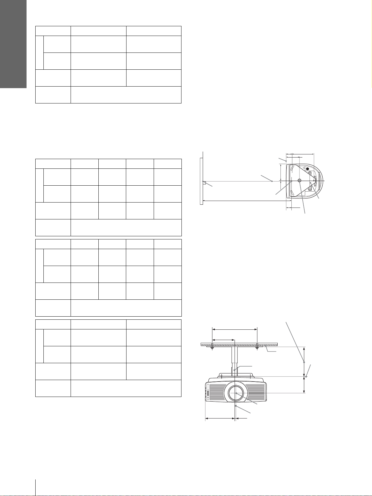
Attaching the projector suspension
support PSS-610
When installing the projector on the ceiling, use the
PSS-610 Projector Suspension Support. For more
details on the ceiling installation, r efer to the
Installation manual for Dealers of the PSS-610. The
installation measu rements are shown be low when you
install the projector on the ceiling.
Installation diagram
Top view
Align the center of the lens with the center of the
screen.
62.1
216.6
1
5
/2)
(2
/8)
(8
Front of the cabinet
165
Center of the unit
Center of the screen
(6
7.9
(5/16)
1
/2)
Center of the lens
Distance between the screen
and the center of the lens
Center of the supporting pole (The center of the
supporting pole is different from that of the unit.)
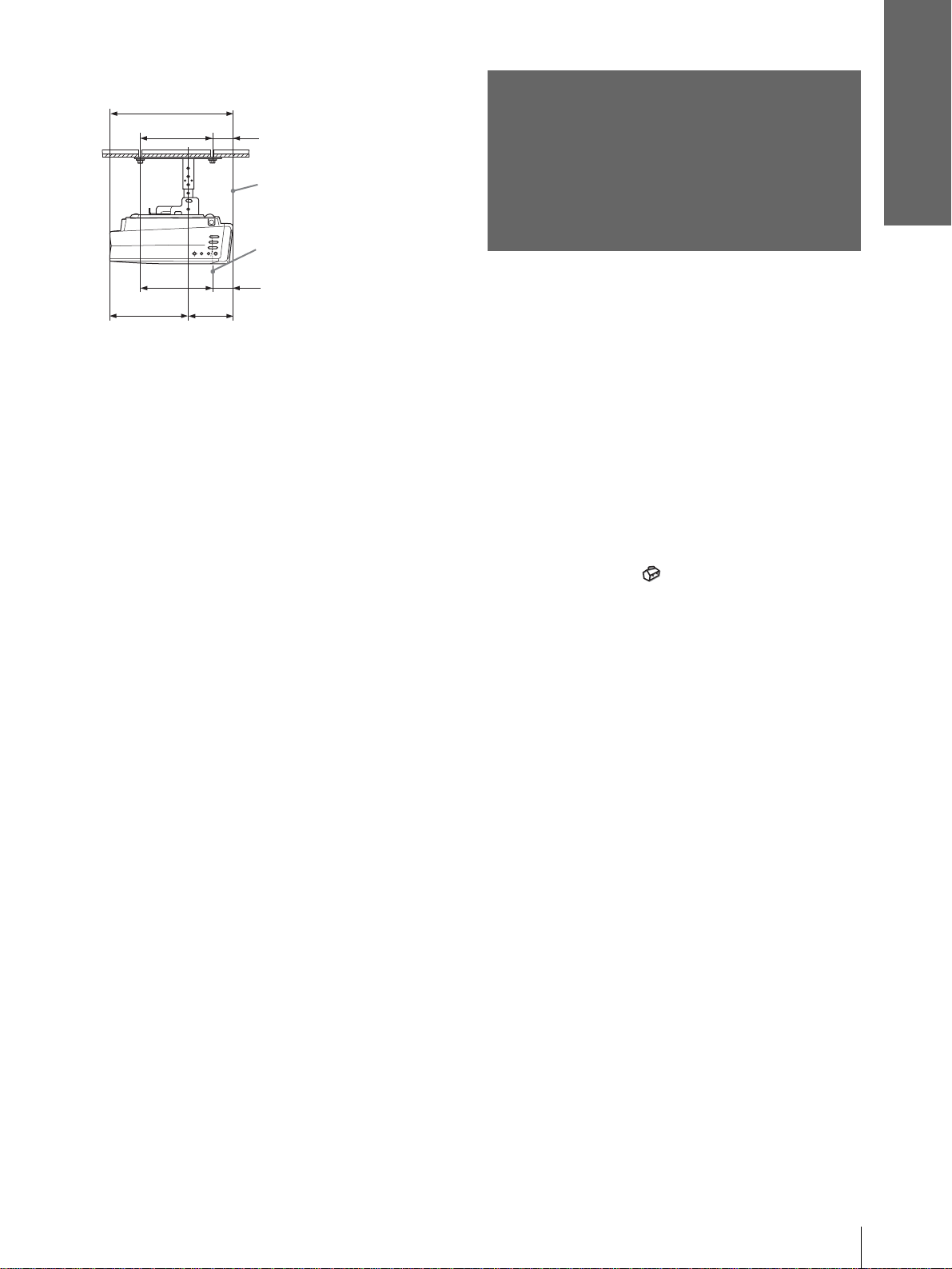
Front view
The lens is offset 7.9 mm (
5
/16 inch) to the right from
the center of the supporting pole. When mounting,
take care to align the center of the lens with the center
of the screen; not the center of the supporting pole.
Distance between the ceiling and the surface of
the mount bracket
Using adjustment pipe (b): 150/175/200 mm
(6 / 7 / 7
Using adjustment pipe (c): 250/275/300 mm
(9 7/8 / 10 7/8 / 11 7/8 inches)
125 (5)
250 (9 7/8)
7
/8 inches)
Center of the
supporting pole
Ceiling
134.2
3
(5
/8)
61.5
Upper ceiling
1
(2
/2)
mount bracket
The bottom
surface of the
mount
bracket
93.3
3
/4)
(3
GB
To calculate the installation measuremen ts (SS: Screen Size)
a (minimum) ={(SS × 33 .5 6/0 . 7 24 0) – 58.520408} × 1.025
a (maximum) ={(SS × 42.35918 19/0.7240 ) – 57.181 415} × 0.975
x = b + (SS/0.7240 × 5.516)
12
Step 1: Installing the Projector
165 (6
Center of the lens
Center of the unit
1
/2)
7.9 (5/16)
Page 13
Side view
Connections and
Preparations
368.5 (14 5/8)
216.6 (8
217.2 (8
234.3 (9 1/4)
5
/8)
5
/8)
134.2 (5 3/8)
62.1
(2 1/2)
Front of the cabinet
Center of the lens
61.5
1
/2)
(2
Unit: mm (inches)
Step 2:
Connecting the
Projector
When making connections, be sure to do the
following:
• Turn off all equipment before making any
connections.
• Use the proper cables for each connection.
• Insert the cable plugs properly; plugs that are not
fully inserted often generate noise. When pulling
out a cable, be sure to pull it out f rom the plug , not
the cable itself.
• Refer to the ope rating i nstructi ons of the connecte d
equipment.
• When you connect your projector to PJ MULTI or
DVI connector, select the input signal with the
“Input-A Signal Sel. ” or “D VI Signal Sel. ” setting in
the SET SETTING menu. (1 page 34)
Note
Before you change the “DVI Signal Sel.” setting, disconnect the
DVI cable and turn off the digital tuner, etc.
------------------------------------------------------------------------------
• HDMI, HDMI logo and High-Definition Multim edi a Int erf ac e
are trademaarks or registered trademarks of HDMI L icensing
LLC.
Step 2: Connecting the Projector
13
GB
Page 14
Connections and
Preparations
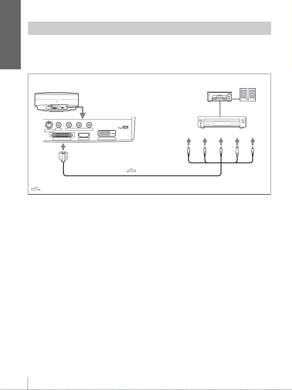
Connecting to a DVD Play er/Digital Tuner
To connect to a DVD player/digital tuner equipped with component video
connectors
You can connect a DVD player/digital tuner e quipped wit h component v ideo conne ctors usi ng the supp lied sig nal
interface cable.
Active
PR/
C
R
speakers
S
Video
Video
S VIDEO
Rear of th e projector
YP
VIDEO
PJ MULTI
B/CB PR/CR
HDMI
with SONY logo upside
AV amplifier
DVD player, digital tuner, etc.,
with component video
connectors
DVI
Y
PB/
C
B
Signal interface cable (SIC-HS41, supplied)
: Video signal flow
Tips
• To connect the projector to a DVD player/digital tuner which is not equipped with component video connectors, use the S video cable of
the DVD player/dig ita l tun er.
• To connect the projector to a DVD player/digital tuner which is not equipped with S video output, use the video cable instead of the S
video cable.
• To connect the projector to a DVD player/digital tun er equipped with a D connector, use a commercially available conversion cable.
GB
14
Step 2: Connecting the Projector
Page 15
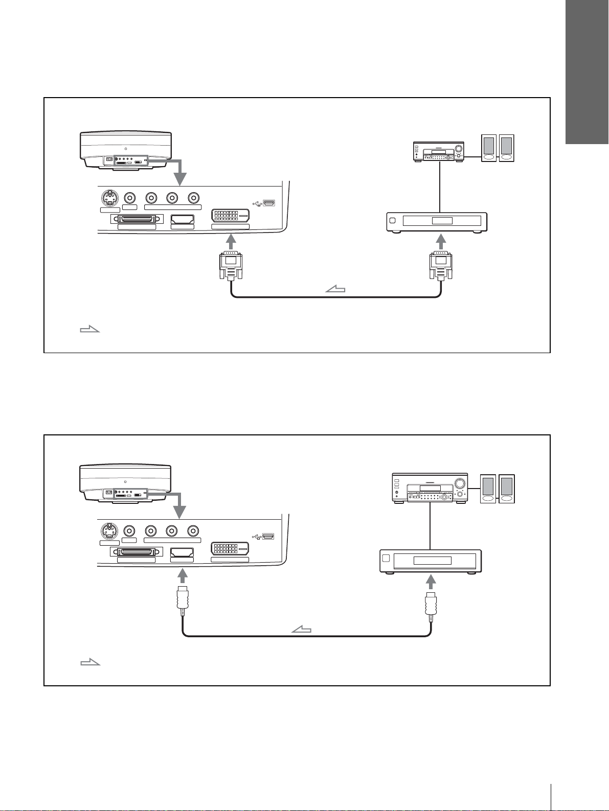
To connect to a digital tuner equipped with DVI output
You can enjoy better picture by connecting a digital tuner equipped with DVI output to the HDMI input of the
projector.
Active
speakers
to DVI output
S VIDEO
VIDEO
PJ MULTI
Rear of the projector
B/CB PR/CR
YP
HDMI
AV amplifier
Digital tuner, etc., with
the DVI output
DVI
Connections and
Preparations
DVI cable (not supplied)
:Video signal flow
To connect to a DVD player equipped with HDMI output
You can enjoy bett er pic ture q ual ity b y co nnecti ng a DVD player/digital tuner equip ped with HDMI output to the
HDMI input of the projector.
Active
speakers
S VIDEO
VIDEO
PJ MULTI
Rear of the projector
YP
B/CB PR/CR
HDMI
A V amp lifier
DVD playeretc., with the
HDMI output
DVI
to HDMI output
: Video signal flow
HDMI cable (not supplied)
Step 2: Connecting the Projector
15
GB
Page 16
Connections and
Preparations
Connecting to Video Equipment
To connect to video equipment equipped with S video or video output
You can connect a VCR, Sony hard disk video recorder “Clip on” or a laser disk player. See also the instruction
manual for each equipment.
S VIDEO
VIDEO
PJ MULTI
Rear of the projector
YP
B/CB PR/CR
HDMI
DVI
Active
speakers
AV amplifier
Video equipment
to S video or
video output
S video or video cable (VMC-810S, not supplied)
: Video signal flow
Tip
If you do n o t know to which c o nn ec to r yo u should connect the c a bl e, S VIDEO (S video c onnector) or VIDEO ( v id eo c onnector), connect
it to S VIDEO (S video connector) to enjoy better picture quality.
If the equipment to be connecte d has no S VIDEO (S video connector), connect the cable to VIDEO (video output).
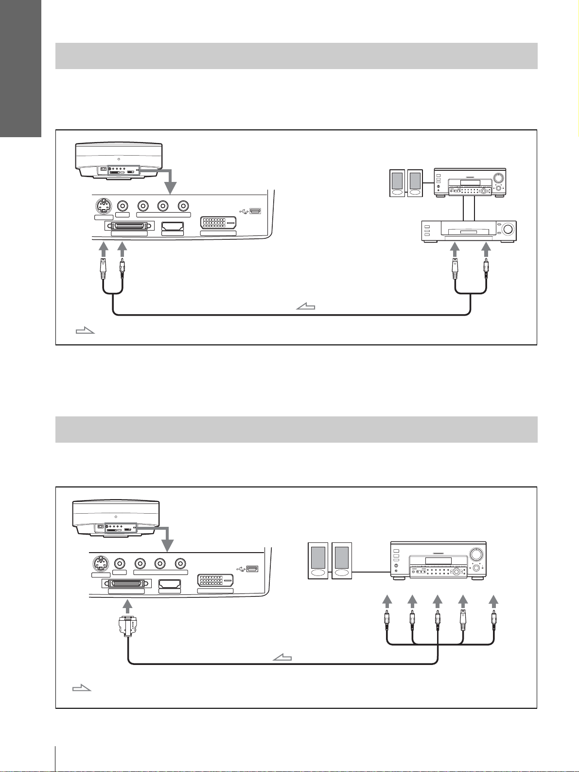
Connecting to an AV Amplifier
You can enjoy better sound quality by connecting the projector to an AV amplifier using the supplied signal
interface cable.
Rear of the projector
AV amplifier
PB/
Y
C
PR/
C
R
B
S
Video
Video
Video outputs
S VIDEO
VIDEO
PJ MULTI
B/CB PR/CR
YP
with SONY logo upside
: Video signal flow
HDMI
Active speakers
DVI
Component
outputs
Signal interface cable (supplied)
GB
16
Step 2: Connecting the Projector
Page 17
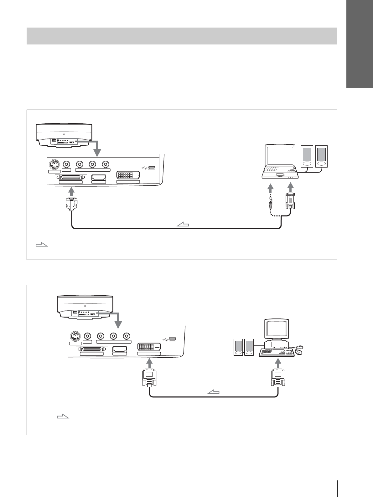
Connecting to a Computer
To connect to an analog connector
To hear the sound from a computer, use the speakers built in the computer or connect the active speakers to the
computer.
You can project a computer’s picture on a large screen using the optional signal interface cable (SIC-HS30).
Note
Even if you connect the signal interface cable to the audio out put on the computer, there is no sound output from the projector.
Rear of the projector
Active
speakers
S VIDEO
VIDEO
PJ MULTI
YP
B/CB PR/CR
HDMI
Computer
DVI
Connections and
Preparations
with SONY logo upside
Signal interface cable (SIC-HS30, not supplied)
: Video signal flow
To connect to the DVI connector
Rear of the projector
YP
S VIDEO
VIDEO
PJ MULTI
B/CB PR/CR
HDMI
to monitor
output
Computer
Active
speakers
DVI
to monitor
output
: Video signal flow
DVI cable (not supplied)
Step 2: Connecting the Projector
17
GB
Page 18
Connections and
Preparations
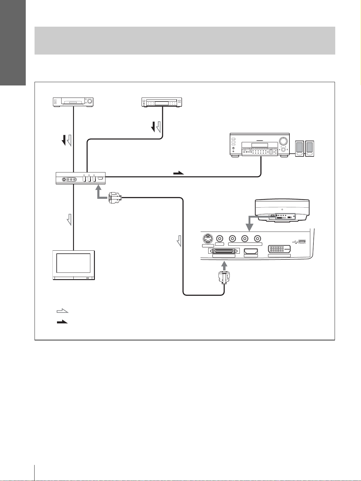
Connecting to V avious Equipment using the Optional Interface
Unit
You can connect other equipment using the optional interface unit. Additionally, you can select output to the
projector or the TV simply by switching the selector of the interface unit.
VCR, etc.
Interface unit
(IFU-HS1, not supplied)
with SONY
logo upside
TV
DVD player, etc.
PJ muti cable
(supplied to IFU-HS1)
S VIDEO
VIDEO
PJ MULTI
Audio amplifier
Rear of the projector
YP
B/CB PR/CR
HDMI
Active
speakers
DVI
: Video signal flow
: Audio signal flow
Note
Audio from the Interface Unit IFU-HS1 is outpu t o nly when a TV is connected.
with SONY logo upside
GB
18
Step 2: Connecting the Projector
Page 19
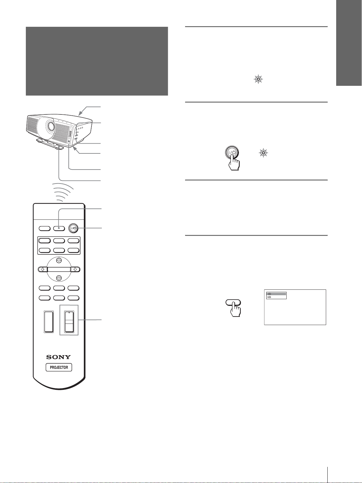
Step 3: Adjusting
the Picture Size
1
Plug the AC power cord into a
wall outlet.
The ON/STANDBY indicator lights in red and
the projector goes into standby mode.
Connections and
Preparations
and Position
Rear remote control
detector
6
5,7
Adjuster adjustment
button
Front remote contro l
detector
Adjuster
4
DYNAMIC
INPUTLIGHT
STANDARD
PICTURE MODE
USER 2
ENTER
CINEMA
USER 3USER 1
2
ON/
Lights in red.
STANDBY
2
Press the [/1 (on/standby)
switch to turn on the projector.
The ON/STANDBY indicator lights in green.
ON/
STANDBY
Lights in green.
3
Turn on the equipment
connected to the projector.
Refer to the operating instructions of the
connected equipmen t.
4
Press INPUT to project the
picture on the screen.
Each time you press the button, the input
indication changes. (1 page 26)
MS SLIDE
MENUAPA
LENS
+
–
RESET
6
WIDE MODE
VOLUME SIDE SHOT
+
–
Tip
The ?/
1 (on/standby), INPUT, MENU, an d M/m/</,/ENTER
(joystick) buttons on the side panel of the projector function the
same as those on the remote cont rol.
INPUT
Video 1
NTSC 3.58
Step 3: Adjusting the Picture Size and Position
19
GB
Page 20
Connections and
Preparations
5
Adjust the focus using the
FOCUS +/– button, and adjust
7
Adjust the picture size and
position.
the picture size using the
ZOOM +/– button.
Screen
Projected picture
ZOOM+/– button
FOCUS +/– button
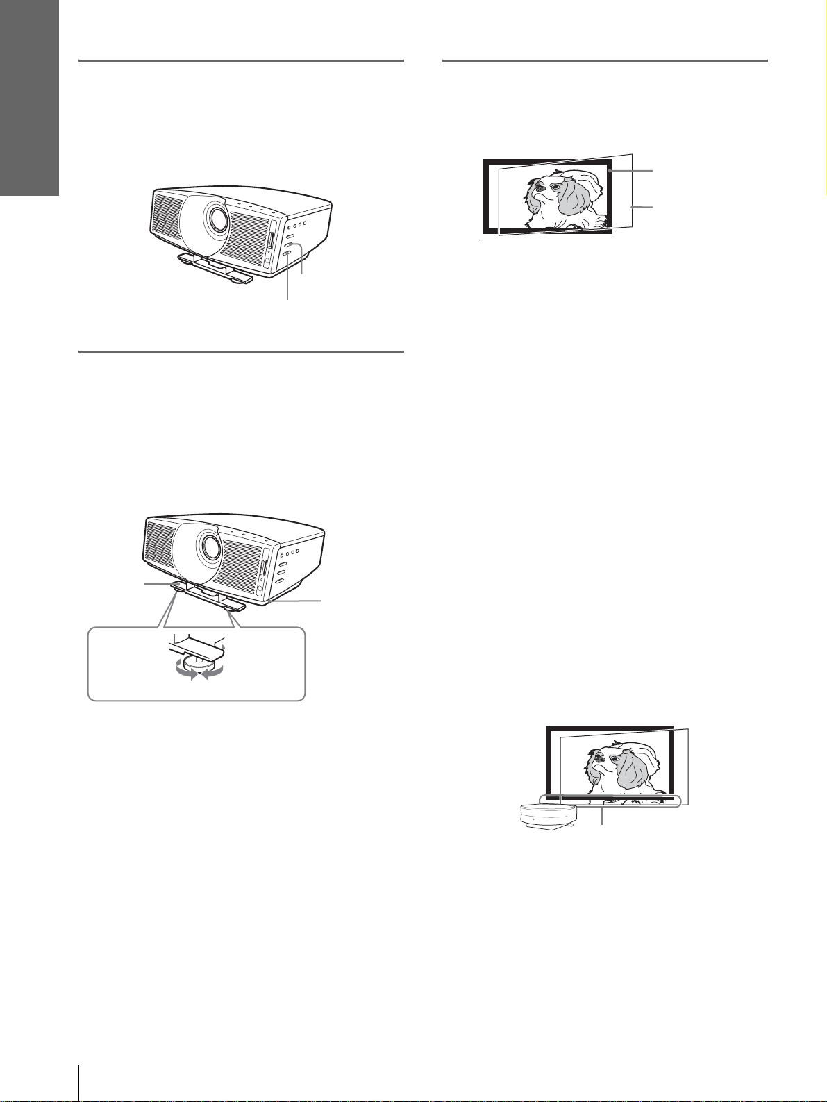
6
Adjust the position of the
picture to fit the screen using
the adjuster.
Adjusting the picture position using
the adjuster
Adjuster
Adjuster
adjustment
button
To lower
To heighten
If “Side Shot” or “V Keystone” are adjusted
manually (valu e adjustment), the built-in te st
pattern is projec ted on th e screen. If you wan t to
make adjustments usi ng the current input signal,
set “Test Pattern” in the INSTALL SETTING
menu to “Off.” (1 page 35)
When projecting using “Side Shot”
adjustment only
When projecting using “Side Shot” adjustment only,
you can adjust to correct horizontal trapezoidal
distortion using the “Side Shot” function to the
maximum.
1 Set “V Keystone” in the INST ALL SETTING
menu to “Manual", press ENTER, then M,
m or RESET to set the level to “0.” The
adjuster is reset.
Note
If “V Keystone” is set to “Auto, ” the correctio n capacity of “S ide
Shot” is reduced.
2 Position the projector so that the pi cture
overlaps on the screen as shown below.
GB
Lift the projector while pressing the adjuster
adjustment button, and release the button.
Holding the adjuster adjustment b utton presse d,
move the projector, then release the button at the
locked position.
To adjust vertically
Lift the projector while pressing the adjuster
adjustment button, then lock the adjuster by releasing
the button at the proper point.
To adjust horizontally
Adjust by turni ng the round pads of the adju ster to the
right or left.
20
Step 3: Adjusting the Picture Size and Position
Adjust so that the bottom side
of the picture is parallel to the
bottom side of the screen.
Check that both vertical sides of the picture are
parallel to the both verti cal sides of the screen.
If the picture does not overlaps on the screen as
shown above, confirm and adjust the installation
position of the projector and screen referring to
Page 21
Connections and
Preparations
“Installin g the Projector and a Scr een” (1 page
9).
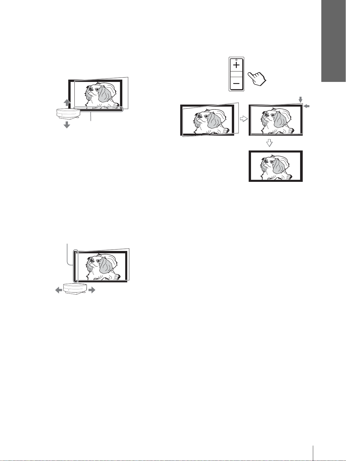
3 Move the projector vertically so that the
bottom side of the picture fits the bottom
inside of the screen frame.
Adjust so that the bottom side
of the picture fits the bottom
inside of the screen frame.
When adjusting the picture height, do not use the
adjuster (1 page 20), but move the projector or
the screen vertically to adjust so that t he bottom
side of the picture fits the bottom inside of the
screen frame.
4 Move the projector horizontally to the left
or right so that one side of the picture fits
the inside end of the screen frame.
Adjust so that one side of the picture fits the
inside end of the screen frame.
5 Adjust to correct horizontal trapezoidal
distortion using the SIDE SHOT + or – .
SIDE SHOT
Press SIDE SHOT + or – so that the upper side
of the picture becomes parallel to the bottom
side. If the ri ght si de is longe r than t he le ft si de,
press SIDE SHOT +. If the left side is longer
than the right side, press SIDE SHO T –. To fineadjust the distortion, press M or m.
Note
Even when projecting us ing “Side Shot”, four sides of a picture
may sometimes not be parallel to the sides of a screen frame.
If you position the proj ector on the le ft sid e of th e
screen, adjust so t hat the left si de of the pictur e fits
the left ins ide end of the screen frame. With the
projector positioned on the right side, adjust so
that the right side of the picture fits the right inside
end of the screen frame.
Note
When adjusting so that one side of the picture fits the inside end
of the screen frame, make sure not to separate the bottom side of
the picture from the bottom inside of th e screen frame.
When projecting using both “Side
Shot” (1 page 35) and “V Keystone”
(1 page 35) adjustments
When projecting using both “Side Shot” and “V
Keystone” adjustments, the vertical and horizontal
distortions are corrected.
1 Check that “V Keystone” in the INSTALL
SETTING menu is set to “Auto."
Note
“V Keystone” in the INSTALL SETTING menu is set to “Auto”
in the default. If it is set to “Auto,” the vertical distortion of the
picture will be automaticall y corrected. The “V Keystone”
adjustment may not correct trapezoidal distortion perfectly,
depending on the room temperature or the screen angle. In th is
case, set manually by value adjustment.
Step 3: Adjusting the Picture Size and Position
21
GB
Page 22
Connections and
Preparations
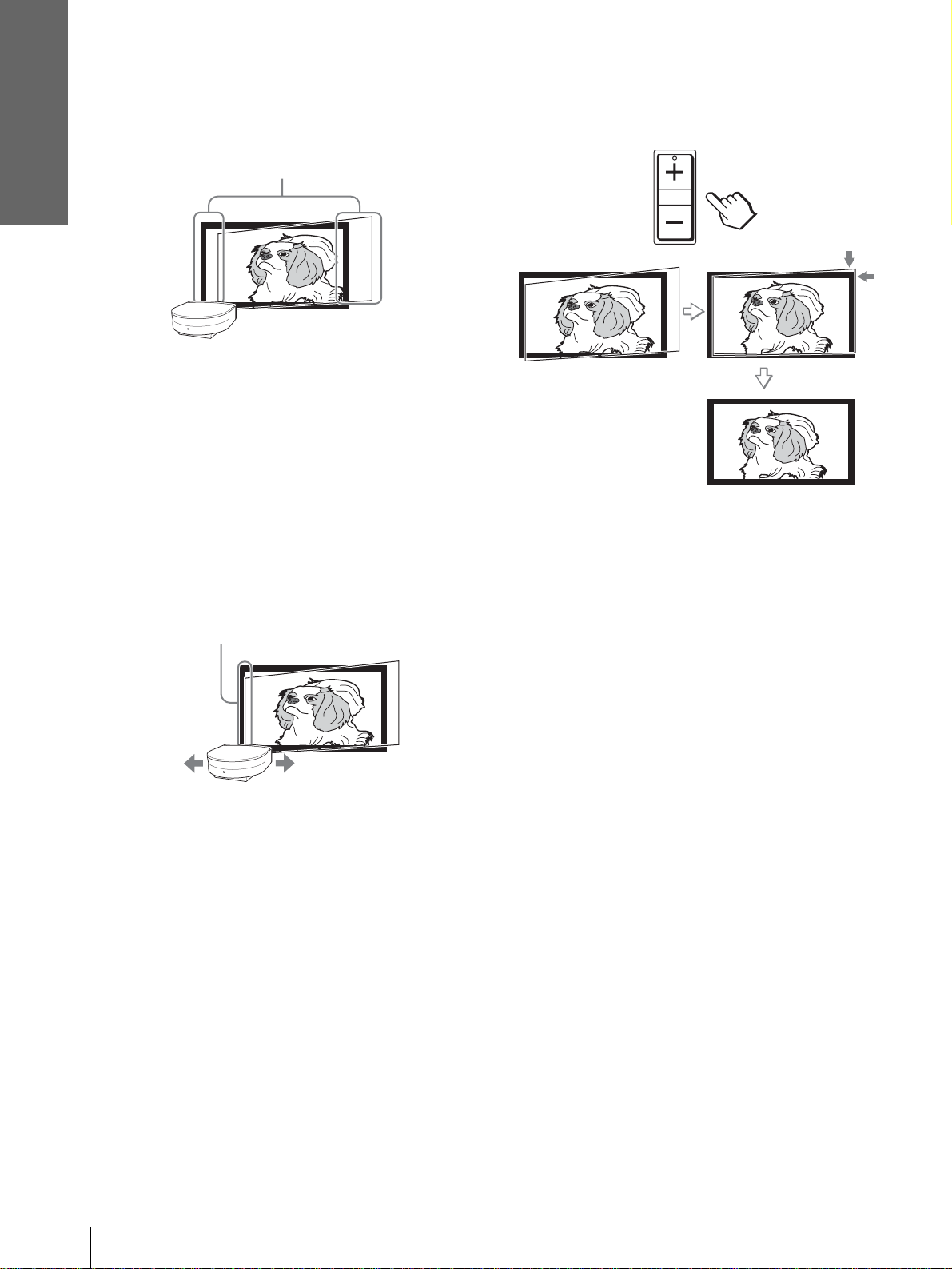
2 Position the projector so that the picture
overlaps on the screen as shown below.
Adjust so that both vertical sides of the picture
are parallel to the both vertical sides of the
screen.
Check that both vertical sides of the picture are
parallel to the both vertical sides of the screen.
If they are not parallel, set “V Keystone” in the
INSTALL SETTING menu to “Manual,” then
press ENTER and adjust the distortion with M or
m so that they be come parallel.
3 Move the projector horizontally to t he left
or right so that one side of the pi cture fits
the inside end of the screen frame.
Adjust so that one side of the picture fits the
inside end of the screen frame.
4 Adjust to correct horizontal trapezoidal
distortion using the SIDE SHOT + or –.
SIDE SHOT
Press SIDE SHO T + or – so that the upper side of
the picture becomes parallel to the bottom side. If
the right side is longer than the left side, press
SIDE SHOT +. If the left side is longer than the
right side, press SIDE SHOT –. To fine-adjust the
distortion, press M or m.
Note
Even when projecting us ing “Side Shot”, four sides of a picture
may sometimes not be parallel to the sides of a screen frame.
If you position the proj ector on the le ft side of the
screen, adjust so th at the left si de of the pictur e fits
the left inside end of the screen frame. With the
projector positioned on the right side, adjust so
that the right side o f the picture f its the right inside
end of the screen frame.
If the picture does not overlap on the screen,
determine and adjust the installation position of
the projector and s creen referrin g to “Install ing the
Projector and a Screen” (1 page 9).
When projecting from the center
1 Check that “V Keystone” in the INSTALL
SETTING menu is set to “Auto."
Note
"V Keystone” in the INSTALL SETTING menu is set to “Auto”
in the default. If it is set to “Auto,” the vertical distortion of the
picture will be automatically corrected. The “V Keystone”
adjustment may not correct trapezoidal distortion perfectly,
depending on the room temp erat ure or the screen angle. In this
case, set manually by value adjustment.
2 Position the projector so that the upper
and bottom sides of the picture are parallel
to the horizontal frame ends of the screen,
and the left and right sides of the picture
are parallel to the vertical frame ends of
the screen, as shown below.
GB
22
Step 3: Adjusting the Picture Size and Position
Page 23
If the picture does not overlap on the screen as
shown above, confirm and adjust the installation
position of the projector and screen referring to
“Installin g the Projector and a Scr een” (1 page
9).
If the left and right sides of the picture are not
parallel to the left and right sides of the screen, set
“V Keystone ” in the INST ALL SETTING menu to
“Manual,” press ENTER, then adjust with M or m
so that they becomes parallel.
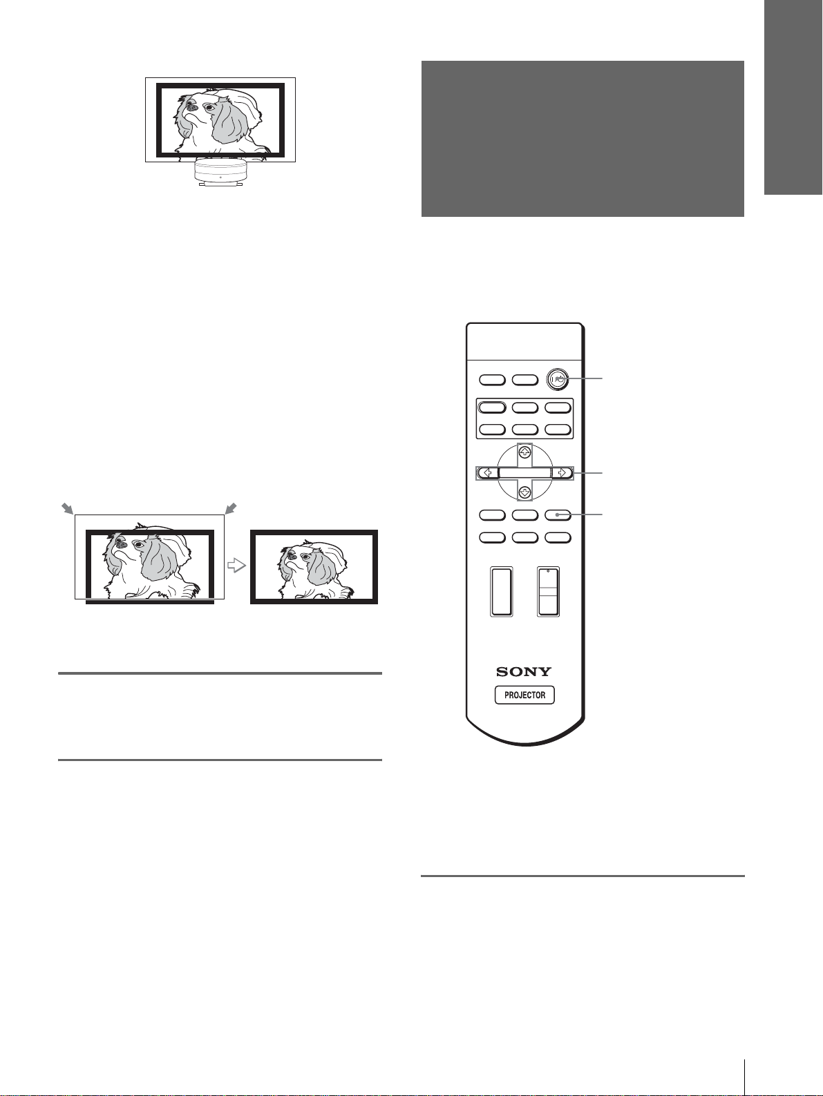
3 Adjust so that both ends of the bottom
side of the picture fit those of the bottom
side of the screen using the adjuster and
the ZOOM + or –.
Step 4:
Selecting the
Menu Language
You can select one of thirteen languages for
displaying the menu and other on-screen displays.
The factory default setting is English.
DYNAMIC
INPUTLIGHT
STANDARD
PICTURE MODE
USER 2
ENTER
CINEMA
USER 3USER 1
2
4-6
Connections and
Preparations
8
Press the FOCUS buttons + or
– to adjust the focus again.
MS SLIDE
MENUAPA
LENS
WIDE MODE
VOLUME SIDE SHOT
+
–
Tip
You can operate the menu using the M/m/</, (arrow) buttons
on the side panel of the projector instead of the M/m/</,/
ENTER buttons on the remote control.
1
Plug the AC power cord into a
RESET
+
–
3
wall outlet.
The ON/STANDBY indicator lights in red and
the projector goes into standby mode.
Step 4: Selecting the Menu Language
23
GB
Page 24
Connections and
Preparations
2
Press the [/1 (on/standby)
switch to turn on the projector.
The ON/STANDBY indicator lights in green.
5
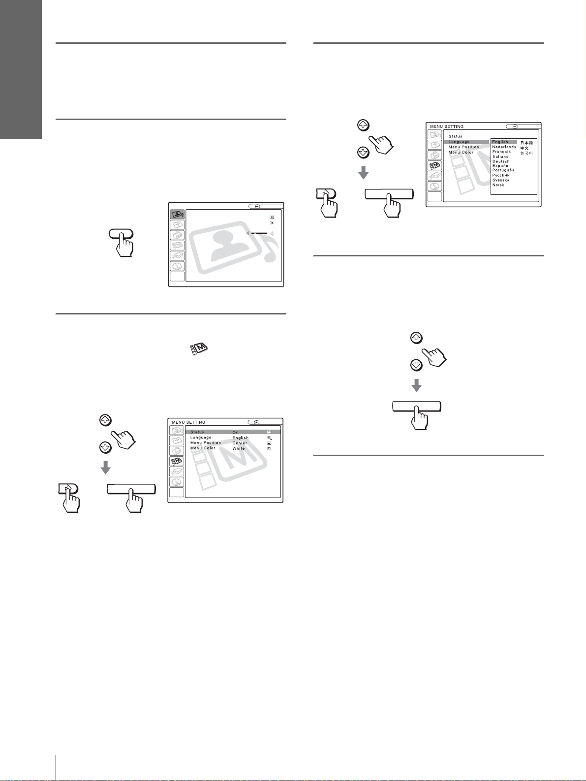
Press M or m to select
“Language”, and press , or
ENTER.
3
Press MENU.
The menu appears.
The menu presently selected is shown as a
yellow button.
PICTURE SETTING
Picture Mode Standard
Adjust Picture...
MENU
4
Press M or m to select the
Volume: 30
MENU SETTING menu, and
press , or ENTER.
The select ed menu appears.
:
:
:
:
Input A
Input A
:
:
:
or
6
Press M or m to select a
ENTER
language, and press ENTER.
The menu changes to the selected language.
ENTER
Input A
:
GB
24
or
Step 4: Selecting the Menu Language
ENTER
To clear the menu
Press MENU.
Page 25
Projecting
Projecting the
This section describes how to operate the
projector to view the picture from the
equipment connected to the projector. It
also describes how to select the wide
screen mode or the quality of the picture to
suit your taste.
Picture on the
Screen
4
INPUTLIGHT
2
STANDARD
USER 2
ENTER
MS SLIDE
LENS
CINEMA
USER 3USER 1
MENUAPA
RESET
+
DYNAMIC
PICTURE MODE
WIDE MODE
VOLUME SIDE SHOT
+
Projecting
–
–
Projecting the Picture on the Screen
25
GB
Page 26
Projecting
1
Plug the AC power cord into a
wall outlet.
The ON/STANDBY indicator lights in red and
the projector goes into standby mode.
ON/
Lights in red.
STANDBY
2
Press the [/1 (on/standby)
switch to turn on the projector.
The ON/STANDBY indicator lights in green.
ON/
STANDBY
Lights in green.
3
Turn on the equipment
connected to the projector.
Refer to the operating instructions of the
connected equipment.
4
Press INPUT repeatedly to
select the input you want to
project on the screen.
Display the indication of the input you want.
To view the picture from
Video equipment connected to
VIDEO INPUT on the projector
Video equipment connected to S
VIDEO INPUT on the projector
RGB/component equipment
connected to PJ MULTI INPUT via
the optional signal interface cable or
the interface unit
Video equipment connected to PJ
MUL TI INPUT via the optional signal
interface cable or the interface unit
Video equipment equipped with S
VIDEO connected to PJ MULTI
INPUT via the optional signal
interface cable or the interface unit
Component equipment connected to
Y / P
B/CB / PR/CR on the projecto r
Digital video equipment connected to
digital (DVI) connector on the
projector
Equipment connected to HDMI
connector on the projector
“Memory Stick” inserted into the
“Memory Stick” slot
*
Set the “Input-A Sig nal Sel.” or “D VI Signal Se l.” setting in the
SET SETTING menu according to the input signal. (1
page 34)
Note
Before you change the “DVI Signal Sel.” setting, disconnect the
DVI cable and turn off the digital tuner, etc.
Press INPUT to
display
Video 1
S-Video 1
*
Input-A
Video 2
S-Video 2
Component
DVI*
HDMI
MS
GB
26
Example:To view the picture from the video
equipment connected to the VIDEO
INPUT jack.
Video 1
INPUT
Projecting the Picture on the Screen
NTSC 3.58
5
Press ZOOM +/– to adjust the
size of the picture.
ZOOM +/– button
Page 27
6
Press FOCUS +/– to adjust the
focus.
Adjust to obtain sharp focus.
Selecting the Wide
Screen Mode
FOCUS +/– button
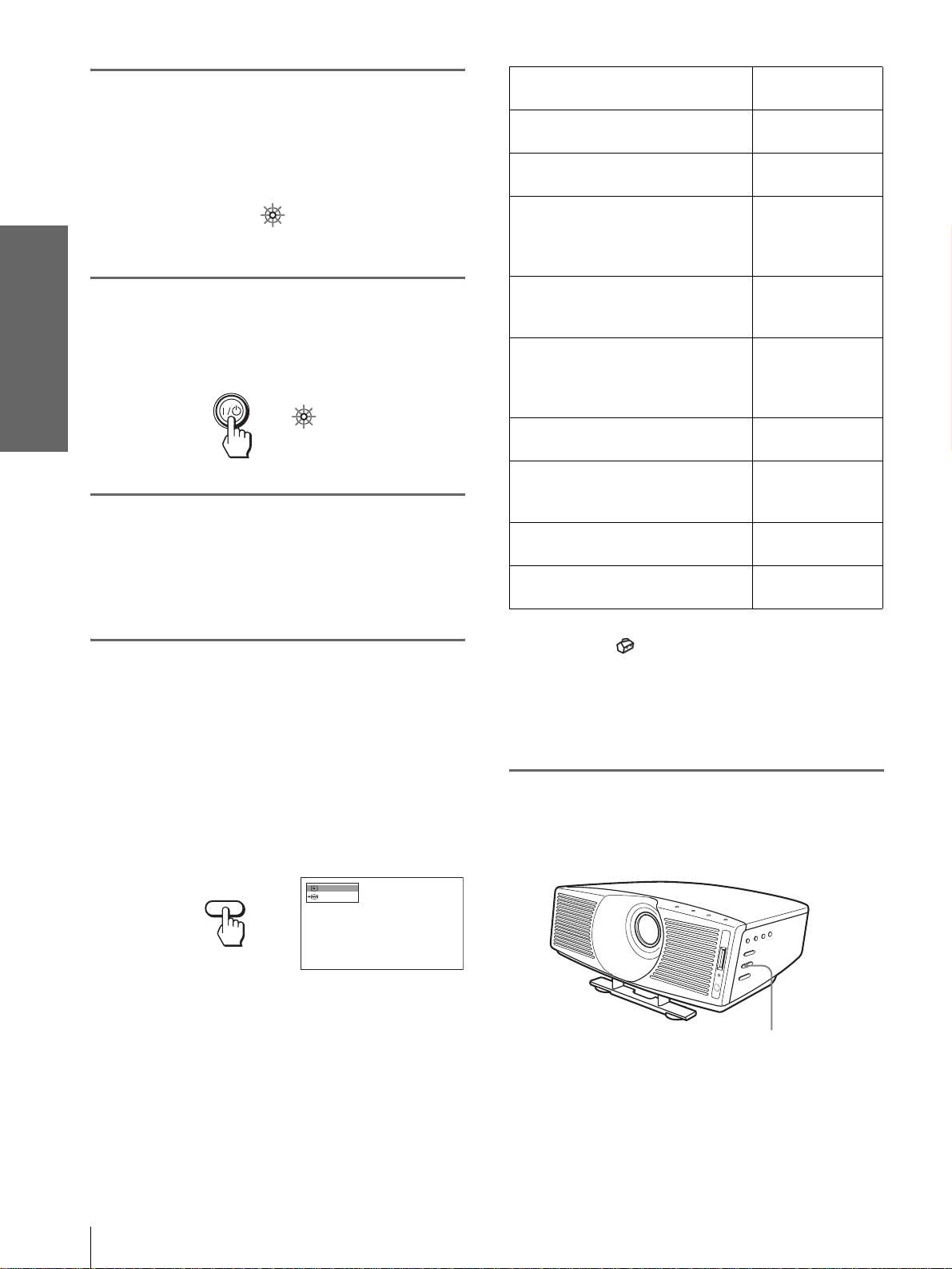
To turn off the power
1 Press the [/1 (on/standby) switch.
A message “POWER OFF?” appears on the
screen.
2 Press the [/1 switch again.
The ON/ST ANDBY indicato r flashes in green and
the fan continues to run to reduce the internal heat.
Also, the ON/ST ANDBY indicat or flashes quickly
during which you will not be able to light up the
ON/STANDBY indicator with the [/1 switch.
3 Unplug the AC power cord from the wall
outlet after the fan stops running and the
ON/STANDBY indicator lights in red.
Y ou can enjo y variou s wide screen mode according to
the video signal rece i v ed. You can also select it usi ng
the menu. (1 page 33)
INPUTLIGHT
STANDARD
USER 2
ENTER
MS SLIDE
LENS
CINEMA
USER 3USER 1
MENUAPA
RESET
+
–
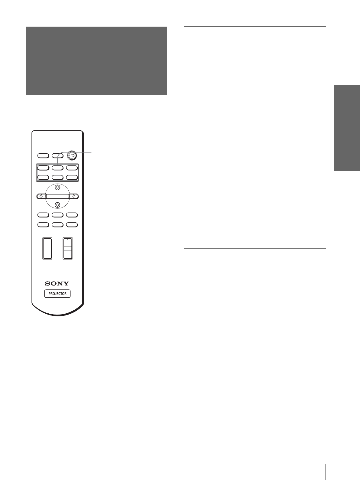
WIDE MODE button
DYNAMIC
PICTURE MODE
WIDE MODE
VOLUME SIDE SHOT
+
–
Projecting
You can turn of f the projec tor b y holdi ng the [/1 (on/
standby) switch for about one second, instead of
performing the above steps.
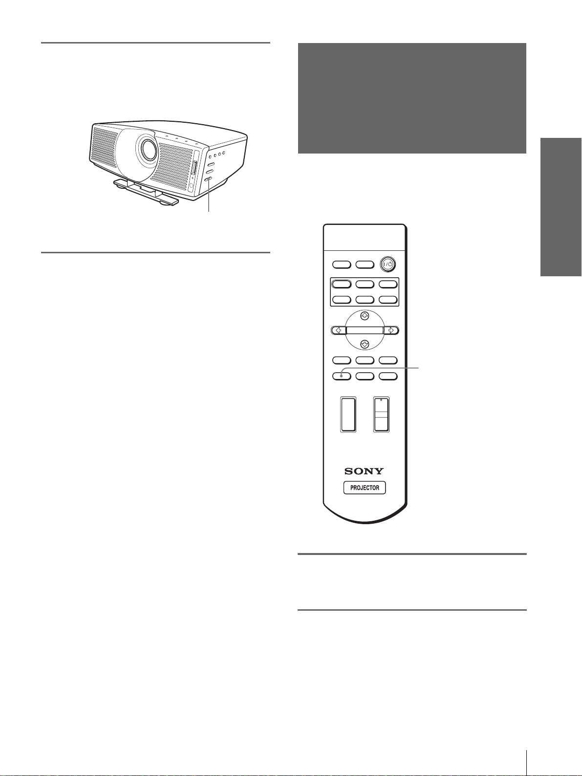
Press WIDE MODE.
Each time you press the button, you can select
the “Wide Mode” setting.
Selecting the Wide Screen Mode
27
GB
Page 28
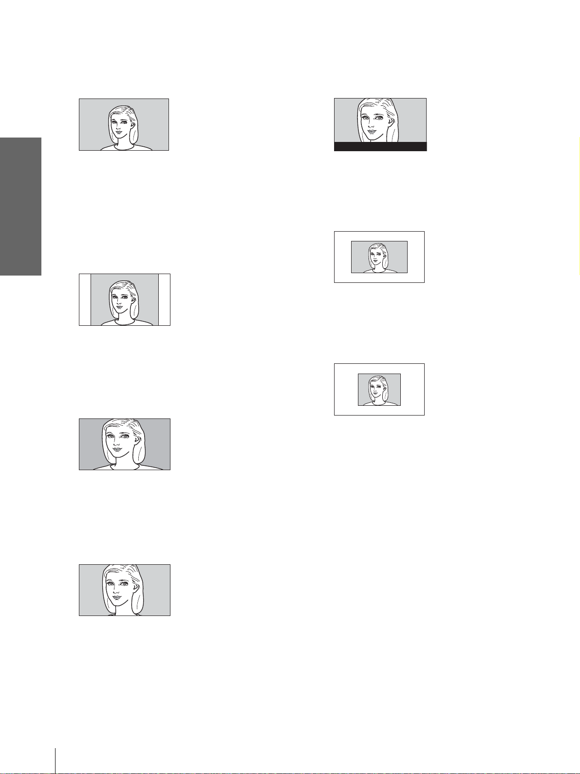
Full
A 16:9 squeezed picture is displayed with the
correct aspect ratio. A 4:3 picture is enlarged
horizontally to fit the 16:9 screen.
Subtitle
The subtitle area is c ompressed and displaye d in
the lower part of the screen. Use this mode to
view a movie with subtitles.
Good-bye
Projecting
Tip
Squeezed: An original 16:9 aspect ratio picture is recorded
horizontally compressed to a 4: 3 picture.
Normal
A picture with normal 4:3 aspect ratio is
displayed in the center of the screen to fill the
vertical screen size.
Wide Zoom
A 4:3 aspect ratio picture is enlarged and the
upper and lower portions of the picture are
compressed to fit the 16:9 screen. Use this mode
to view news, variety shows, etc.
Zoom
A normal 4:3 aspect ratio picture is enlarged
vertically and horizontally in the same ratio to
fill the 16:9 sc reen. This mode is ideal fo r
viewing a wide-format movie.
Full Through
One-to-one mapping i s done on a sque ezed 16:9
picture. It is displayed in the center of the
screen.
Normal Through
One-to-one mapping is done on a 4:3 normal
aspect ratio picture. It is displayed in the center
of the screen.
Notes
• You can adjust the vertical position of the picture with “V
Position” in the INPUT SETTING menu only when “Zoom” or
“Subtitle” is selected.
• You can adjust the position of the subtitles with “Title Area” in
the INPUT SETTING menu only when “Subtitle” is selected.
• If “Full Through” or “Normal Through” is selected when a
video signal o f the Mem ory No . 1, 2, 3, 4, 43 or 4 4 (ref er to the
“Preset Signals” chart) is input, you cannot adjust “V
Keystone” or “Side Shot” in the INSTALL SETTING menu.
Notes on selecting the wide screen mode
• Select the wide screen mode taking into account
that changing the a spect rati o of the ori ginal picture
will provide a different look fr om that of the
original image.
• Note that if the projector is used for profit or for
public viewing, modifying the original picture by
switching to the wide mode may constitute an
infringement of the rights of authors or producers,
which are legally protected.
GB
28
Selecting the Wide Screen Mode
Page 29
Selecting the
Picture Viewing
Press one of the PICTURE
MODE buttons (DYNAMIC,
STANDARD, CINEMA and
USER 1, 2 and 3).
Mode
You can select the picture viewing mode that best
suits the type of program or room condition.
INPUTLIGHT
STANDARD
DYNAMIC
PICTURE MODE
USER 2
ENTER
MS SLIDE
LENS
WIDE MODE
VOLUME SIDE SHOT
+
+
CINEMA
USER 3USER 1
MENUAPA
RESET
PICTURE MODE buttons
DYNAMIC
STANDARD
CINEMA
USER 1, 2 and 3
DYNAMIC
Select for enhanced picture sharpness in bright
environment.
STANDARD
Recommended for normal vi e wing co ndition in
your home.
CINEMA
Select for soft, film-like picture in dark
environment.
USER 1, 2 and 3
You can adjust the quality of the picture to suit
your taste and store the settings into the selected
memory of the project or . Press one of the USER
1, 2 and 3 buttons, then ad just the pict ure by
using the menus. The settings are stored, and
you can view the picture with the adjusted
picture quality b y press ing the button. (1 page
32)
Projecting
–
–
Selecting the Picture Viewing Mode
29
GB
Page 30
Display items
Using the
Menus
This section describes how to make
various adjustments and settings using the
menus.
Input signal indicator
Video 1
NTSC 3.58
Input signal setting indicator
Picture adjustment menu
Contrast
Input signal indicator
Shows the selected input channel. is displayed
when no signal is input. You can hide this indicator
using “Status” in the MENU SETTING menu.
Input signal setting indicator
For Input-A: Shows “Computer,” “Component” or
“Video GBR.”
For Digital : Shows “Computer” or “Video GBR.”
For V ideo/S Video input: Sho ws “Auto” or the “Color
System” setting in the SET SETTING menu.
x
Operation through
the Menus
The projector is equipped with an on-screen menu fo r
making various adj ustment s and set tings . The set ting
items are displayed in a pop-up menu or in a sub
menu. If you select an item name followed by dots
(...), a sub menu with setting items appear. You can
change the tone of the menu display and the menu
language displayed in the on-screen menu.
To change the menu language, see “Selecting the
Menu Language” on page 23.
INPUTLIGHT
STANDARD
DYNAMIC
PICTURE MODE
USER 2
ENTER
MS SLIDE
LENS
WIDE MODE
VOLUME SIDE SHOT
+
–
+
–
CINEMA
USER 3USER 1
MENUAPA
RESET
2-4
1
GB
30
Operation through the Menus
Page 31

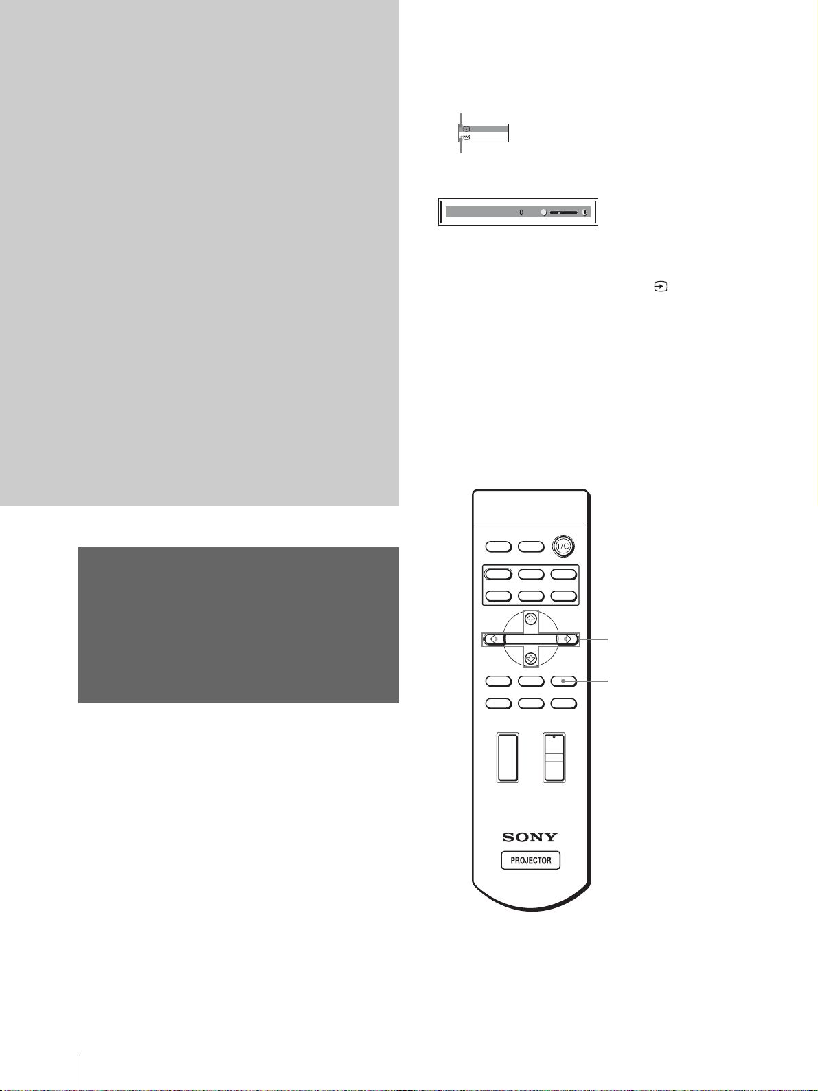
1
Press MENU.
The menu appears.
The menu presently selected is shown as a
yellow button.
SET SETTING
Smart APA: On
Auto Input Search:
Input-A Signal Sel.:
MENU
2
Press M or m to select a menu,
Color System: Auto
Power Saving: Off
Illumination: Off
Off
and press , or ENTER.
The selected menu ap pears.
Computer
Input A
4
Make the setting or adjustment
on an item.
When changing the adjustment level
To increase the value, press M or ,.
To decrease the value, press m or <.
Press ENTER to restore the original screen.
When changing the setting
Press M or m to change the setting.
Press ENTER to restore the original screen.
You can restore the original scre en using <
depending on the selected item.
To clear the menu
Press MENU.
Using the Menus
3
Press M or m to select an item
you want to adjust and press
, or ENTER.
The setting items are displayed in a pop-up
menu or in a sub menu.
Pop-up menu
Menu Setting items
:
:
:
:
or
ENTER
Sub menu
Menu Setting items
PICTURE SETTING
ADJUST PICTURE
Contrast: 80
Brightness: 50
RGB Enhancer: 30
Gamma Correction: Graphics
Color Temp:
Standard
High
Input A
Input A
To reset items that have been
adjusted
Select the item you want to reset, then press RESET.
“Complete!” appears on the screen and the setting is
reset to its factory preset valu e.
Items that can be reset are:
• “Contrast,” “Brightness,” “Color,” “Hue” and
“Sharpness” in “Adjust Picture...” of the PICTURE
SETTING menu
• “Dot Phase,” “H Size” and “Shift” in “Adjust
Signal...” of the INPUT SETTING menu
• “V Keystone” (when set to “Manual”) and “Side
Shot” of the INASTALL SETTING menu
Operation through the Menus
31
GB
Page 32

Menu Items
Menu Lists
Adjustable items are limited according to the input
signals. Items that cannot be adjusted are not
displayed in the menu. (1 page 71)
PICTURE SETTING
Item Description
Picture Mode You can select picture viewing mode that
Menu Configu rations
The projector is equipped with six pages. The items
that can be adjusted in each menu are described on
page 32.
PICTURE SETTING menu
The PICTURE SETTING menu is used for adjust ing
Using the Menus
the picture. You can also adjust the vol ume (a v ailab le
only for “Memory Stick”).
INPUT SETTING menu
The INPUT SETTING menu is used to adjust the
input signal. You can adjust the size of the picture, and
select wide screen mode, etc.
SET SETTING menu
The SET SETTING menu is used for changing the
settings of the projector.
MENU SETTING menu
The MENU SETTING menu is used to change the
display position, int ensity of the background picture,
etc., of the menu screen.
INSTALL SETTING menu
The INST ALL SETTI NG menu is used for cor recting
distortion of the picture.
INFORMATION menu
The INFORMATION menu is used to display the
horizontal and ver tical freq uencies of the inp ut signal
and the used time of the lamp.
Volume Adjusts the volume.
Adjust Picture…
Contrast The higher the setting, the greater the
Brightness The higher the setting, the brighter the
Color The higher the setting, the greater the
Hue The higher the setting, the more greenish
Sharpness The higher the setting, the sharper the
best suits the type of picture or the
environment.
Dynamic: Select for enhanced picture
contrast and sharpness.
Standard: Recommended for normal
viewing condition. Also select to reduce
roughness when viewing the picture
with Dynamic.
Cinema: Select for soft, film-like picture.
User 1, 2 and 3: You can adjust the
quality of the picture to suit your taste
and store the settings. Once the settings
are stored, you can view the picture with
the adjusted picture quality by pressing
the PICTURE MODE button.
To store the settings
1 Select User 1, User 2 or User 3.
2 Adjust the items you want in the
menus.
Items that can be stored are:
“Adjust Picture...” items other than
“Volume,” and “Wide Mode” setting
Tip
You can also adjust the picture quality
in “Dynamic”, “Standard” or “Cinema”
mode. To reset to the factory setting,
press RESET.
Tip
Audio is output only when a movie file
stored in a “Memory Stick” is played.
contrast. The lower the setting, the lower
the contrast.
picture. The lower the setting, the darker
the picture.
intensity. The lower the setting, the lower
the intensity.
the picture becomes. The lower the
setting, the more purplish the picture
becomes.
picture. The lower the setting, the softer
the picture.
GB
32
Menu Lists
Page 33

Item Description
Black Level
Adj (Adjust)
Emphasizes black color to produce a
bolder “dynamic” picture. Set according
to the input signal source.
High: Gives higher emphasis to the black
color.
Low: Gives lower emphasis to the black
color.
Off: Cancels this feature.
Gamma
Correction
Off: Cancels this feature.
Gamma1, Gamma2, Gamma3: Can
adjust, set and store the favorite tone
using the specified controller
“ImageDirector”
(*1)
.
Color Temp. High: Gives the white colors a blue tint.
Middle: Gives the white colors a neutral
tint.
Low: Gives the white colors a red tint.
Custom1, Custom2, Custom3: Can
adjust, set and store the favorite color
temperature.
DDE
(Dynamic
Detail
Enhancer)
Off: Plays a video signal in an interlace
format without converting.
Progressive: Conv erts an i nterlace format
video signal to a progressive format.
Film: Normally, select this option.
Reproduces the 2-3 Pull-Down film
sources with smooth picture movement.
When the video signal with a format
other than the 2-3 Pull-Down is input,
“Progressive” is automatically selected.
Cinema
Black Pro
Iris Control
Switches the iris function during
projection.
Off: Normal contrast.
On: Enhances the black by emphasizing
the contrast.
Lamp Control
Switches the lamp wattage during
projection.
High: Normal wattage.
Low: Enhances the black by reducing the
lamp wattage.
Tip
If “Lamp Control” is set to “Low,” the ne xt ti me
the power is turned on, the lamp will use the
“High” setting initially, and then go to “Low.”
*1: You can downlo ad free “ImageDirector” from URL described
below.
UK: http://www.sony.co.uk
Canada: http://www.sonystyle.c a /productsupport
South-east Asia: http://www.css.ap.sony.com
South America: http://www.sony-latin.com/WEGA
INPUT SETTING
Item Description
Adjust Signal…
Dot Phase Adjusts the picture from a computer for
H Size Adjusts the horizontal size of the picture
Shift As the setting for H (horizontal)
Wide Mode You can select the 4:3 aspect ratio picture
clearer picture after it is adjusted by
pressing the APA button.
from a computer. The higher the setting,
the wider the picture. The lower the
setting, the narrower the picture.
increases, the picture moves to the right,
and as the setting decreases, the picture
moves to the left. Use < or , to adjust
the horizontal position.
As the setting for
V (vertical) increases,
the picture moves up, and as the setting
decreases, the picture moves down. Use
M or m to adjust the vertical position.
mode, “Normal” and “Normal Through,”
and 16:9 aspect ratio picture mode,
“Full,” “W ide Zoom, ” “Zoom, ” “Subtitle”
and “Full Through.”
Full: The 16:9 squeezed* picture is
diplayed with the correct aspect. The
4:3 picture is enlarged horizontally to
fit the 16:9 screen.
* squeezed: An original 16:9 aspect
ratio picture is recorded horizontally
compressed to be a 4:3 picture.
Normal: The picture with normal 4:3
aspect ratio is displayed to fill the
vertical screen size.
Wide Zoom: The picture with 4:3 aspect
ratio is enlarged and the upper and
lower portions of the picture are
compressed to fit the 16:9 screen. Use
this mode to v i ew news, va r i et y shows,
etc.
Zoom: The normal 4:3 aspect ratio
picture is enlarged verticall and
horizontally at the equal ratio to fill the
16:9 screen. The mode is ideal for
viewing a wide-format movie.
Subtitle: The subtitle area is compressed
and displayed at the lower part of the
screen. Use this mode to view a movie
with the subtitle.
Full Through: One-to-one mapping is
done on a squeezed 16:9 picture. It is
displayed in the center of the screen.
Normal Through: One-to-one mapping
is done on the picture with 4:3 aspect
ratio. It is displayed in the center of the
screen.
Note
If “Full Through” or “ N ormal Through” is
selected whe n a video sign al of the Me mory No.
1, 2, 3, 4, 43 and 44 (refer to the “Preset
Signals” chart) is input, you cannot adjust “V
Keystone” or “Side Shot” in th e INSTALL
SETTING menu.
Using the Menus
For details, see “Selecting the Wide
Screen Mode” on page27
”.
Menu Lists
33
GB
Page 34

Item Description
V Position Adjusts the vertical position of the picture
in wide screen mode. As the setting
increases, the picture moves up. As the
setting decreases, the picture moves
down.
Note
This item is adjustable only when “Zoom” or
“Subtitle” is selected.
Title Area Adjusts the subtitle area. As the setting
increases, the subtitle area moves up. As
the setting decreases, the subtitle area
moves down.
Note
This item is adjustable only when “Subtitle” is
selected.
Note
For input signals from the DVI and HDMI connector, “Dot
Phase,” “H size” and “Shift” are not adjustable.
SET SETTING
Item Description
Smart APA With this item set to On, the APA function
Auto Input
Search
Input-A Signal
Sel.
works automatically for a signal input from
a computer so that the picture can be seen
clearly. You can also activate the APA
function by pressing the AP A b utton on the
remote control.
Tip
The APA (Auto Pixel Alignment) automatically
adjusts the input sig n al from a computer so that
the picture can be seen clearly.
Set to On when an optional Interface Unit
such as the IFU-HS1 is connected to the PJ
MULTI connector on the projector.
Selects the signal input from the equipment
by selecting “Input-A” with the INPUT
button.
Computer: Inputs the signal from a
computer.
Component: Inputs the component or
progressive component signal from a
DVD player, digital tuner, etc.
Video GBR: Inputs the signal from a TV
game or HDTV broadcast.
Using the Menus
DVI Signal
Sel.
Selects the signal input from the equipment
by selecting “Digital” with the INPUT
button.
Computer: Inputs the signal from a
computer.
Video GBR: Inputs the signal from a
digital tuner, etc.
Note
Before you change the “DVI Signal Sel.” setting,
disconnect the DVI cable and turn off the digital
tuner , etc.
Color System Select the color system of the input signal.
Auto: Selects the color system of the input
signal automatically from among NTSC,
PAL, SECAM, NTSC
4.43, PAL-M or
PAL-N.
“NTSC3. 58”–“PAL-N”: Sets the color
system to the selected system manually.
Power Saving When set to On, the POWER SAVING
indicator lights. The projector goes into
power sav i ng mod e if no si g nal i s input for
10 minutes, and the lamp goes out and the
cooling fan keeps running. In power saving
mode, no button functions for the first 60
seconds. It is cancelled when a signal is
input or any button is pressed. If you do not
set the projector to power saving mode,
select Off.
Illumination Turns on the illumination on the top panel
of the projector when set to On. It turns off
when set to Off.
GB
34
Menu Lists
Page 35

MENU SETTING INSTALL SETTING
Item Description
Status Set to Off to turn off the on-screen
displays except for the menus, message
when turning off the power, and warning
messages.
Language Selects the lang ua g e used in the menu and
on-screen dis plays. Available languages
are: English, Dutch, French, Italian,
German, Spanish, Portuguese, Russian,
Swedish, Norwegian, Japanese, Chinese,
and Korean.
Menu Position Selects the display position from Top
Left, Bottom Left, Center, Top Right
and Bottom Right.
Menu Color Selects the tone of the menu display from
White or Black.
Item Description
V Keystone Corre cts the vertical trapezoidal distortion
Side Shot Corrects the horizontal trapezoidal
Image Flip Flips the picture on the screen horizontally
Background Selects the background color of the screen
Test Pattern When set to On, a test pattern is displayed
High Altitude
Mode
of the picture. ( )
Auto: Normally set to this postion.
Manual: Sets a lower value (– direction)
when the bottom of the trapezoid is
longer than the top. Sets a higher value
(+ direction) when the top of the
trapezoid is longer than the bottom. If
you project the picture using “Side
Shot” only, set to “Manual,” and adjust
the level to “0.”
Note
The “V Keystone” adjustment may not correct
the trapezoidal distortion perfectly, depending on
the room temp erature or the screen angle.
distortion of the picture. ( )
Set the level to “0” when you adjust the
picture using “V Keystone” only.
Note
Even when projecting using “Side Shot”,
four sides of a picture may sometimes not
be parallel to the sides of a screen frame.
and/or vertically.
Off: The picture does not flip.
HV: Flips the picture horizontally and
vertically.
H: Flips the picture horizontally.
V: Flips the picture vertically.
when no signal is input. You can select
“Black” or “Blue.”
on the screen when adjusting using the
“Lens Zoom,” “Lens Focus,” “Side Shot”
or “V Keystone.” If you do not want to
display a test pattern, set to Off.
Off: Use this setting when using the
projector at normal altitudes.
On: Use this setting when using the
projector at an altitude of 1,500 m or
higher.
Using the Menus
INFORMATION
Item Description
fH Displays the horizontal frequency of the
input signal.
fV Displays the vertical frequency of the input
signal.
Lamp Timer Indicates how long the lamp has been
turned on.
Menu Lists
35
GB
Page 36

About the Preset Memory
Adjusting Picture Quality of
No.
This projector has 35 types of preset data for input
signals (the preset memory ). When the preset signal is
a Signal from the Computer
You can automatically adjust to obta in the cleares t
picture when projecting a signal from the computer.
input, the projector automatically detects the signal
type and recalls th e data for the s ignal fr om the preset
memory to adjust it to an optimum picture. The
memory number and signal type of that signal are
displayed in the INFORMATION menu.
INFORMATION
fH: 48.47kHz
fV: 60.00Hz
No.23
1024x768
Lamp Timer: 0H
Input A
Memory No.
Signal type
Using the Menus
Y ou can als o adjust the preset da ta through the INPUT
SETTING menu.
This projector also has 20 types of user memori es for
Input-A into which you can save the setting of the
adjusted data for an unpreset input signal.
When an unpreset signal is input for the first time, a
memory number is displayed as 0. When you adjust
the data of the s ig nal in th e I N PUT SETTI NG menu ,
it will be registered to the projector. If more than 20
user memories are registered, the newest memory
always overwrites the oldest one.
See the chart on page 73 to find if the signal is
registered to the preset memory.
Since the data is recalled from the p reset memory
about the following signals, you can use these preset
data by adjusting “H size.” Make fine adjustment by
adjusting “Shift.”
1 Project a still picture from the computer.
2 Press the APA (Auto Pixel Alignment)
button.
When the picture is adj usted properly , “complete!”
appears on the screen.
Notes
• When “Smart APA” is set to “On,” the APA function is
automatically activated.
• Press the APA button when the image appears on the whole
display area of the computer. If there are black edges around the
image, the APA function will not function properly and the
image may extend beyond the screen.
• If you switch the in put signal or re-conn ect a computer, press
the APA button again to get the suitable picture.
• To restore the original screen, press the APA button again
during the adjustment.
• When a signal of which the timing is the same as the “Memory
No.23” or the “Memory No.72” signal (refer to the “Preset
Signals” chart) is input, if the polarity of the synchronized
signal is different, the input signal may be misjudged and the
image may not appear properly (incorrect aspect ratio or lack of
a part of the image). In this case, press the APA button to adjust
the image. This APA processing time may be longer than the
APA processing time of si gnal in another case. If the image
does not still appear properly, input the signal as described in
the following example, then press the APA button again.
Example:
display of whitish wallpaper with a window’s bar in the lower
part
• The picture may not be adjusted properly depending on the
types of input signals.
• Adjust the items in the INPUT SETTING menu when you
adjust the picture manually. (1 page 32)
GB
Signal Memory No. H size
Super Mac-2 23 1312
SGI-1 23 1320
Macintosh 19” 25 1328
Note
When the aspect ratio of input signal does not match the screen
size, a part of the screen is displayed in black.
36
Menu Lists
Page 37

Using a
“Memory
Stick”
This section describes how to view the
picture files that are recorded by a digital
camera and stored in a “Memory Stick.”
You can make a slide show using the
pictures, display an index screen of the
pictures, etc.
About a “Memory
Stick”
Types of “Memory Stick”
“Memory Stick” is availa ble in the follo wing six types
to meet various requirements in functions.
• “Memory Stick PRO”
Equipped with the MagicGat e cop y right pr otect ion
technology and can be used only with “Memory
Stick PRO” compliant products.
•“Memory Stick”
Stores any type of data except copyright-protected
data that requires the MagicGate copyright
protection technology.
• “Memory Stick” (compatible with “MagicGate”/
high speed data transfer)
Equipped with the “Magic Gate” copyright
protection and compatible with high speed data
transfer. This “Memory Stick” can be used wi th a ll
“Memory Stick” compliant produc ts. The projecto r
is not compatible with the high speed data transfer
function of this “Memory Stick.”
• “MagicGate Memory Stick”
Equipped with the MagicGat e cop y right pr otect ion
technology.
•“Memory Stick-ROM”
Stores pre-recorded, read-only data. You cannot
record on “Memory Stick-ROM” or erase the prerecorded da ta.
• “Memory Stick” (with memory select function)
This is a “Memory Stick” that has (128MB) plural
memory in it.
You can select memory to use for whatever
purposes through the memory select switch on the
back of the “Memory Stick”.
Y ou cannot use all the avai lable memory at the same
time and/or continuously.
Using a “Memory
Stick”
What is “Memory Stick”?
“Memory Stick” is a new compact, portable and
versatile IC (Integrated Circuit) recording medium
with a data capacity that exceeds a floppy disk.
“Memory Stick” is specia lly designed f or exchangin g
and sharing digital data among “Memory Stick”
compatible products. Because it is removable,
“Memory Stick” can also be used for external data
storage.
“Memory Stick” is available in two sizes: standard
size and compact “Memory Stick Duo” size. Once
attached to a Memory Stick Duo adaptor, “Memory
Stick Duo” turns to the same size as standard
“Memory Stick” and thus can be used with products
compliant with standard “Memory Stick.”
About a “Memory Stick”
37
GB
Page 38

Av ailable types of “Memory Stick” f or
the projector
Note on memory capacity of “Memory
Stick PRO”
“Memory Stick PRO” features vary by and are
Memory Stick Media Compatibility Chart
Playback
“Memory Stick”
“Memory Stick” (with memory select
function)
“Memory Stick Duo”
“Memory Stick” (compatible with
MagicGate/high speed data transfer)
“Memory Stick Duo” (compatible with
“MagicGate”/high speed data transfer)
“Memory Stick-ROM”
“MagicGate Memory Stick”
“MagicGate Memory Stick Duo”
“Memory Stick PRO”
“Memory Stick PRO Duo”
*1: Data playbak that requ i re s Ma gicGate functions canno t be
performed.
*2: Does not support high speed data transfer using the parall el
interface.
*1 *
1
*
*1 *
2
2
• When using a “Memory Stick Duo” in the projector ,
always insert the “Memory Stick Duo” into the sold
separately “Memory Stick Duo” adaptor. If you
insert a “Memory Stick Duo” wi thout the “Memory
Stick Duo” adaptor, you may be unable to remove
dependent upon the design of host hardware devices.
“Memory Stick PRO” Media slot:
• does not support MagicGate copyright protection
technology;
• does not support access control security function.
This device has been demonst rated the oper ation with
up to 1GB “Memory Stick”. Operation is not
guaranteed for “Memory Stick PRO” beyond this
capacity.
Notes on “Memory Stick Duo”
• To use “Memory Stick Duo” with your projector,
attach it to the “Memory Stick Duo” adaptor be fore
inserting it into your projector.
If you insert a “Memory Stick Duo” without the
“Memory Stick Duo” adaptor, you may be unable to
remove the “Memory Stick Duo”.
• Be sure to attach “Memory Stick Duo” to the
adaptor with the correct orientation.
• Be sure to insert the Memory Stick Duo adaptor
with the correct orientation. Otherwise, the
projector may be damaged.
• Do not insert the Memory Stick Duo adaptor
without “Memory Stick Duo” attached. Doing so
may result in malfunction of the projector.
the “Memory Stick Duo”.
Using a “Memory
Stick”
• Not all types of “Memory Stick” media are
guaranteed to operate.
Note on “Memory Stick PRO” and
Note on data read/write speed
Data read/write speed may vary depending on the
combination of the “Memory Stick” and “Memo ry Stick”
compliant product you use.
“Memory Stick” (compatible with
“MagicGate”/high speed data transfer
“Memory Stick PRO” and “Memory Stick”
(compatible with “MagicGate”/high speed data
transfer) do not suppor t high speed data tran sfer using
the parallel interface.
Note on access control
This unit cannot read “Memory Stick” that has been
Access Control with other units. To read/write data on the
Access Control “Memory Stick”, unlock the “Memory
Stick” with the unit that has locked it.
GB
Note on “Memory Stick” (compatible
with “MagicGate”/high speed data
transfer)
Transfer speed when using “Memory Stick”
(compatible with “MagicGate”/high speed data
transfer) varies and is dependent upon “Memory
Stick” compliant products.
38
About a “Memory Stick”
Note on “Memory Stick” (with
memory select function)
• Y ou ca nnot use all t he av ailable memory at the same
time and/or continuously.
• Do not use the memory select switch while the
“Memory Stick” is connected to any of the
compatible device that is co mpatible for use with
this feature, as this may cause a mal function. If you
use the memory select functi on while the “Memory
Stick” is connected to any compatible device and
there is a malfunction, we will not honor the
guarantee.
Page 39

• When using the memory select switch, make sure to
firmly move the switch to the end. If you do not
switch it completely, it may cause a problem or
malfunction.
• Check your memory selection on the “Memory
Stick” bef ore inserting it into the “Memory Stick”
slot of the compatible device.
• When you use “Memory Stick” with memory selec t
function, you can choose the type of memory by
switching the memory se lect switch. As the
compatible device will only access the memory
selected by you, note the following:
- A formatting (initializing) process is executed for
the selected memory only.
- Remaining memory display reflects only selecte d
memory information.
- Error display reflects only selected memory
information.
Each memory is handled individually by selecting it.
What is MagicGate ?
MagicGate is copyright protection technology that
uses encryption technology.
Format that can be displayed with this
projector
The projector can di splay the picture files reco rded by
a digital camera and r ecorded on a “Memory Stick” i n
the following format:
• Image files (DCF-compatible) compressed in the
JPEG (Joint Photographic Experts Group) format
(extension: .jpg)
• MPEG1 format picture files recorded by Sony
products; MPEG MOVIE, MPEG MOVIE AD,
MPEG MOVIE EX, MPEG MOVIE HQ, MPEG
MOVIE HQX, MPEG MOVIE CV, VAIO Giga
pocket (equivalent to video CD).
Before using a “Memory Stick”
Terminal
Write-protect
tab
by mistake when using “Memory Stick” which is
not equipped with a write-protect tab.
• Use a sharp object, suc h as a ballpoint pen , to move
the “Memory Stick Duo” erasure pr even tion switch.
• Data may be damaged if:
- You remove the “Memory Stick” or turn off the
unit while it is reading or writing data.
- Y ou use the “Memor y Stick” in a locat ion subject
to the effects of static electricity or electric noise.
• We recommend that you make a backup copy of
important data that you record on the “Memory
Stick.”
Notes
• Do not attach anything other than the supplied label to the
“Memory Stick” labeling position.
• Attach the label so that it does not stick out beyon d the labeling
position.
• Do not write forcefully on the “Memory Stick Duo” memo
area.
• C arry and store the “Memory Stick” in its case.
• Do not touch the connector of the “Memory Stick” with
anything, including yo ur finger or metallic objects.
• Do not strike, bend, or drop the “Memory Stick.”
• Do not disassemble or modify the “Memory Stick.”
• Do not allow the “Memory Stick” to get wet.
• Do not use or store the “Memory Stick” in a location that is:
- Extremely hot, such as in a car parked in the sun
- Under direct sunlight
- Very humid or subject to corrosive substances
About formatting “Memory Stick”
When “Memory Sticks” are shipped from the f actory ,
they are already formatted to a special standard. When
you format “Memory Stick,” we recommend
formatting them on this projector.
Caution when formatting “Memory Stick” on
a personal computer
Pay attention to the fo llowi ng points when formatti ng
“Memory Stick” on a personal computer. Operation
of “Memory Stick” formatte d on a personal comput er
is not guarante ed on this projector. To use a “Memory
Stick” that has been formatted on a personal
computer, the “Memory Stick” must be reformatted
on this projector. If it is not reformatted, all data
stored on the “Memory Stick” will be lost.
Using a “Memory
Stick”
Labeling
position
• When you set the “Memory Stick” erasure
prevention switch to “LOCK,” data cannot be
recorded, edited, or erased.
• Some “Memory Sticks” (“Memory Stick PRO”/
”Memory Stick PR O Duo”) are not equipped with a
write-protect tab. Make sure not to edit or erase data
Access Indicator
If the access indicator is turned on or is flashing, data
is being read from or written to the “Memory Stick.”
At this time, do n ot shake the project or or subject it to
shock. Do not turn off the power of the projector or
remove the “Memory Stick.” This may damage the
data.
About a “Memory Stick”
39
GB
Page 40

Precautions
• To prevent data loss, make backups of data
frequently. In no event will Sony be liable for any
loss of data.
• Unauthorized recording may be contrary to the
provisions of copyright law.
• The “Memory Stick” application software may be
modified or changed by Sony without prior notice.
Preparing for Viewing
the Picture Files Stored
in a “Memory Stick”
Inserting a “Memory Stick”
.....................................................................................
• “Memory Stick Duo” and are trademarks of
Sony Corporation.
• “ Memory Stick” and are tra demarks of Sony
Corporation.
• “Memory Stick PRO” and are trademarks
of Sony Corporation.
• “MagicGate Memory Stick” and are trademarks
of Sony Corporation.
• “Memory Stick-ROM” and are trademarks
of Sony Corporation.
Insert the “Memory Stick” into the “Memory Stick”
slot on the front of the projecto r.
Be sure to insert the “Memory Stick” in the correct
direction.
“Memory St ick”
Insert the “Memory Stick” in the
direction of the arrow until it clicks.
Label for preventing
incorrect insertion
Using a “Memory
Stick”
GB
40
To remove the “Memory Stick”
When the access indicator is turned off, press the
“Memory Stick” and remove your hand. As the lock
is released, remove the “Memory Stick.”
Access indicator
Note
Insert the “Memory Stick” with the arrow mark pointing toward
the “Memory Stick” slot.
Preparing for Viewing the Picture Files Stored in a “Memory Stick”
Page 41

Displaying the Desired Pictures
in Digital Camera Mode
INPUT button
INPUTLIGHT
STANDARD
USER 2
ENTER
MS SLIDE
LENS
CINEMA
USER 3USER 1
M/m/</,/ENTER
buttons
MENUAPA
RESET
+
–
DYNAMIC
PICTURE MODE
WIDE MODE
VOLUME SIDE SHOT
+
–
Press INPUT to select MS.
Memory Stick Home appears.
Notes
• The digital camera mode does not function if more than 2000
picture files recorded by a digital camera are stored in a
“Memory Stick.”
• For a picture file recorded with the Voice Memo function of the
Sony digital camera, only the still picture file is displayed.
• If you delete a picture file with the relative file mark ( ),
its relative picture file will also be deleted.
Tip
Several small pictu res includ ed in a folder , displaye d at one time,
are called thumbnails.
Before operating the picture file
To operate the picture f i le, display the index menu or
the picture setting menu.
Index menu
To display the index menu, select a thumbnail, then
press ENTER.
You can perform the following operations using the
menu displayed on the index screen:
- Displaying a picture file on the full screen
- Executing the slide show
- Protecting an important picture file
- Rotating a picture file (still picture only)
- Registering the startup picture file (still picture
only)
- Deleting a picture file
Memory Stick
Home mark
Memory Stick Home
Slide Show
Option
Filter : Still
Select Folder
Digi.Camera Mode
No :
Size :
Appears if another fi le with the same name in the
last four figures is included in the “Memory
Stick.”
Appears the first 20 thumbnails
File :
Date :
What is Digital Camera Mode?
The projector can choose and display JPEG and
MPEG1 picture files recorded by a digital camera
(DCF-compatible) only from among picture files
stored in a “Memory Stick.”
Picture setting menu
Menu of a still picture
To display the picture setting menu, press ENTER
when a picture is displayed on the ful l screen. Y ou can
perform the following operations using the menu
displayed on the picture setting scr een :
- Showing/hiding the picture file information
- Protecting an important picture file
- Rotating a picture fil e
- Registering the startup picture file
- Deleting a picture file
Menu of a movie file
T o display the picture set ting menu, select “Menu” on
the Movie Player.
You can perform the following operations using the
menu displayed on the picture setting screen:
- Showing/hiding the movie file information
- Switching the sound to be heard
- Protecting an important movie file
- Deleting a movie file
For details o n operati ons, se e the des cription for each
screen.
Using a “Memory
Stick”
Preparing for Viewing the Picture Files Stored in a “Memory Stick”
41
GB
Page 42

Index screen of a still picture file
Appears when
startup is set.
Appears when a fil e is
protected.
Memory Stick Home
Slide Show
Option
Filter : Still
Select Folder
Digi.Camera Mode
Index menu
Full Screen
Slide Show
Protect
Rotate
Startup
Delete
Close
Index screen of a movie file
Appears when the
displayed picture
is a movie.
Appears when a file
is protected.
Memory Stick Home
Slide Show
Option
Filter : Still
Select Folder
Digi.Camera Mode
Index menu
Movie Player
Slide Show
Protect
Rotate
Startup
Delete
Close
No : 123/1234
Size : 1024x768
Resolution
Order/total
number of
picture files
T o select a picture file in the thumbnail display, press
M, m, < or ,. If you want to displa y oth er picture
files when more than 20 pict ure f i les a re con taine d in
the current folder, select a picture file in the bottom
row and press m, or select a file on the right-most
column, press , to select the slide r, then press m. If
you press MS SLIDE in the index menu, the slide
show starts from the selected picture.
File : 100MSDCF/SJP0001.JPG
Date : 2003/JUL/15 12:34PM
Date
File name and file
format
No : 123/1234
Size : 352x240
Resolution
Order/total
number of
File : 100MSDCF/SJP0001.MPG
Date : 2003/JUL/15 12:34PM
Date
File name and file
format
picture files
Picture setting screen of a still picture
Picture setting menu
Return
Information
On
Protect
Rotate
Startup
Delete
Close
Using a “Memory
No : 1/1234
Stick”
Size : 1024x768
Resolution
Order/total number
of picture files
Appears when
startup is set.
Appears when a
file is protected.
File : 100MSDCF/SJP0001.JPG
Date : 2003/JUL/15 12:34PM
Date
File name and
file format
GB
42
If you want to display another picture file when
multiple picture files are contained in the current
folder, press ,. If you press MS SLIDE in the
picture setting menu, th e screen returns to Memory
Stick Home.
Preparing for Viewing the Picture Files Stored in a “Memory Stick”
Page 43

Movie Player
Picture setting menu
of a movie file
Prev.
Full Screen
Menu
NEXT
Information
On
Audio Select
Return
Delete
No : 1/1234
Size : 320x240
L/R
Protect
Close
Resolution
Order/total number
of picture files
Movie icon
Appears when a
file is protected.
File : SJP0001.MPG
Date : 2003/JUL/15 12:34PM
Date
File name and file
format
Using a “Memory
Stick”
Preparing for Viewing the Picture Files Stored in a “Memory Stick”
43
GB
Page 44

The slide show settintg menu appears.
Viewing the
Pictures
Viewing the Pictures in
Sequence — Slide Show
You can run a slide show by using the pictures
recorded by a digital camera. Y ou can advance a slide
automatically or manually.
INPUTLIGHT
STANDARD
USER 2
ENTER
CINEMA
USER 3USER 1
DYNAMIC
PICTURE MODE
2-5
Slide show setting menu
Memory Stick Home
Slide Show
Option
Filter : Still
Select Folder
Digi.Camera Mode
No :
Size :
Start
Execute
Effect
Off
Off
Advan. Slds.
Manual
Interval
5sec
1sec
Repeat
5sec
On
10sec
30sec
40sec
Beenden
File :
Date : 2002/MAY/31 1:08PM
Effect: to set the effect when the slide is
displayed.
Advan. Slds. (Advance Slides) : to set to
advance a next slide automatically (“Auto”)
or manually (“Manual”).
Interval: to set the per iod for which on e slide is
displayed. When “Advan. Slds.” is set to
“Manual,” this item does not work. Th e time
is about right.
Repeat: set to execute the slide show
repeatedly or one time only.
MS SLIDE
Using a “Memory
WIDE MODE
VOLUME SIDE SHOT
Stick”
+
–
LENS
+
–
MENUAPA
RESET
MS SLIDE button
3
Press M or m to select the
setting item, and press
ENTER.
4
Press M or m to set the
selected item, and press
1
Display the Memory Stick
Home. (1 page 41)
2
Press M or m to select “Slide
Show,” and press ENTER.
ENTER.
Memory Stick Home
Slide Show
Option
Filter : Still
Select Folder
Digi.Camera Mode
Start
Effect
Off
Advan. Slds.
Auto
Interval
10sec
1sec
5sec
10sec
Close
20sec
30sec
40sec
No : 123/1234
Size : 1024x768
File : 123/1234
Date : 2002/MAY/31 1:08PM
GB
44
Viewing the Pictures
Page 45

5
After setting all the items,
press M or m to select “Start”
and press ENTER.
When you set “ Advan. Sld s.” to “ Auto, ” the slide
advances automatically. When a movie picture
is selected , it is played automaticall y, and after
playback the next slide is displayed.
When you set to “Manual,” use the , b utton to
advance a slide. To return to the previous slide,
use the < button. The movie picture is not
played back and the first frame of the picture is
displayed. To play back the movie pictures, see
“Playing Movie Pictures” on page 46.
Displayi ng a Picture on the
Full Screen — Full Scre e n
You can project one of the index pictures on the full
screen. To display a movie picture on the ful l sc reen,
see “Playing Movie Pictures” on page 46.
INPUTLIGHT
STANDARD
USER 2
CINEMA
USER 3USER 1
DYNAMIC
PICTURE MODE
To end the slide show
Press MS SLIDE or ENTER when you set “Advan.
Slds.” to “Auto.”
When setting it to “Manual,” press MS SLIDE.
To return to the Memory Stick Home
before executing the slide show
Select “Close” in step 5 above.
Executing the slide show promptly
As the settings are st ored ev en if you change t he input
after performing st eps 1 to 4, press MS SLIDE just as
you start the slide show. The input is changed to MS
and the slide show starts promptly.
To start a slide show from the
selected index picture
You can run a slide show by selecting a thumbnail in
the index screen.
1 Press M, m, < or , to select the picture
file from which you want to start the slide
show, and press ENTER.
2 Press M or m to select “Sl ide Sho w” in the
index menu of a still pictu re file/mov ie file,
and press ENTER.
ENTER
2-3
MS SLIDE
MENUAPA
LENS
WIDE MODE
1
Display the Memory Stick
RESET
Home. (1 page 41)
2
Press M, m, < or , to select
a still picture you want to
display on the full screen, and
press ENTER.
The index menu of a still picture file appears.
Index menu of a still picture file
Memory Stick Home
Slide Show
Option
Filter : Still
Select Folder
Digi.Camera Mode
MS SLIDE button
Full Screen
Slide Show
Protect
Rotate
Startup
Delete
Close
Using a “Memory
Stick”
No : 123/1234
Size : 1024x768
File : 100MSDCF/SJP0001.JPG
Date : 2003/JUL/15 12:34PM
Viewing the Pictures
45
GB
Page 46

3
Press M or m to select “Full
Screen,” and press ENTER.
The selected picture is projected to fit the
screen.
Playing Movie Pictures
You can play back a movie of MPEG1 format
recorded with the Sony MPEG MOVIE, etc.
INPUTLIGHT
STANDARD
USER 2
CINEMA
USER 3USER 1
DYNAMIC
PICTURE MODE
WIDE MODE
ENTER
MS SLIDE
LENS
MENUAPA
RESET
2-4
MS SLIDE button
No : 1/1234
Size : 1024x768
File : 100MSDCF/SJP0001.JPG
Date : 2003/JUL/15 12:34PM
2003/JUL/15 12:34PM
To display a previous or next slide
To display the next slide, press ,.
To return to the previous slide, press <.
To return to the Memory Stick Home
Press MS SLIDE.
You can also return to the Memory S tick Home by
using the index menu. Press ENTER to display the
index screen of a still picture file, press M or m to
select “Return” and press ENTER.
Using a “Memory
Stick”
1
Display the Memory Stick
Home. (1 page 41)
2
Press M, m, < or , to select
a movie picture you want to
display, and press EN TER.
The index menu of a movie file appears.
Index menu of a movie file
Memory Stick Home
Slide Show
Option
Filter : Still
Select Folder
Digi.Camera Mode
Movie Player
Slide Show
Protect
Rotate
Startup
Delete
Close
GB
46
Viewing the Pictures
No : 124/1234
Size : 320x240
File : 100MSDCF/BASEBALL.MPG
Date : 2003/JUL/15 12:34PM
Tip
When you select a movie picture in the index screen, “Rotate” and
“Startup” are not available.
Page 47

3
Press M or m to select “Movie
Player,” and press ENTER.
The Movie Player appears.
Prev.
Next
To stop playback
Press m to select x.
To play a movie on the full screen
Press M or m to select “Full Screen” in the Movie
Player, and press ENTER.
The picture is enlar ged to f ill the screen a nd playback
starts. When you press M, m, <, , or ENTER
during playback, the Movie Player is restored.
Full Screen
Menu
Return
No : 124/1234
Size : 320x240
File : BASEBALL.MPG
Date : 2003/JUL/15 12:34PM
N (play/pause): to play back. During playback,
the button display is changed to the X (pause)
button.
x (stop): to stop playback.
Full Screen: to play a full-screen movie picture.
Menu: to display the movie picture setting menu.
[Guide display]
< Previous: to display the previous slide in the
movie pause mode. During playback the guide
display is changed to < “Rew” (rewind).
, Next: to display t he next slide in the movie pause
mode. During playback the guide display is
changed to , “FF” (fast-forward).
Tip
The Movie Player is not displayed when you set “Advan. Slds.” of
“Slide Show” to “Auto.”
Note
When the picture size is small, it is not enlarged to f il l the scre en
if you select “Full Screen.”
To return to the Memory Stick Home
Press M or m to select “Return.”
To switch the sound to be heard
1 Press M or m to select “Menu.”
The movie picture setting menu appears.
2 Press M or m to select “Audio Select.”.
3 Press VOLUME + or – to adjust the sound.
Movie picture setting menu
Prev.
Full Screen
Menu
Return
NEXT
Information
On
Audio Select
L/R
Protect
Delete
Close
Using a “Memory
Stick”
4
Press M or m to select N.
Playback starts. When the playback is finished,
playback stops wi th the firs t picture of the mo vie
displayed.
Note
The projector can play back a MPEG1 movie recorded by the
Sony MPEG MOVIE, etc. (Movies may occasionally skip when
you watch them.) Usable MPEG1 movies are MPEG MOVIE
AD/EX/HQ/HQX/CV, MPEG1 of VAIO Giga pocket (equivalent
to a video CD).
No : 1/1234
Size : 320x240
File : SJP0001.MPG
Date : 2003/JUL/15 12:34PM
L/R: to hear the left and right sounds.
L: to hear the left sound.
R: to hear the right sound.
Viewing the Pictures
47
GB
Page 48

Selecting the Folder
Containing the Desired Picture
1 Display the Memory Stick Home.
Note
Set “Digi. Camera Mode” to “Off” be fore operation. (1 page
48)
2 Press M or m to select “Select Folder ,” and
press ENTER.
The folder list appears.
Current folder
Memory Stick Home
Slide Show
Option
Filter : Still
Select Folder
Digi.Camera Mode
Off
Close
Folder list
Tip
Multiple picture files are included in the folder. The folder
may include individual still or movie picture files and other
folders. You must select fold ers when you are displaying a
picture file stored in a “Memory Stick.”
To turn off the Digital Camera Mode
1 Display the Memory Stick Home.
2 Press M or m to select “Select Folder ,” and
press ENTER.
3 Press M or m to select “Digi. Camera
Mode,” and press ENTER.
4 Press m to select “Off,” and press ENTER.
The folder list appears.
Folder list
Memory Stick Home
Slide Show
Option
Filter : Still
Select Folder
Digi.Camera Mode
Off
DCIM/100MSDCF
No :
Size :
T o uppe r
stage
Using a “Memory
Stick”
3 Press , to select the folder list.
Memory Stick Home
Slide Show
Option
Filter : Still
Select Folder
No :
Size :
Digi.Camera Mode
Off
Close
File :
Date :
First picture file in the
current folder
File :
Date :
No :
Size :
Close
File :
Date :
4 Press M or m to select the fol der which
contains the picture file you want to
display, and press ENTER.
T o select the folders which are not displayed, pres s
, to select the slider on the folder list and press
v or V. The next 10 folders appear.
GB
48
Viewing the Pictures
Page 49

Rotating a Still
Picture
You can rotate a thumbnail picture or full-screen still
picture clockwise or counterclockwise in 90º steps.
Note
You cannot rotate a movie picture.
3
Press M or m to select
“Rotate,” and press ENTER.
4
Press M or m to select the
direction of rotation,
(clockwise) or
(countercloc k wise), and press
ENTER.
The picture rotates 90° every pressing of the
ENTER button.
To rotate the full-screen still picture
INPUTLIGHT
STANDARD
PICTURE MODE
USER 2
ENTER
CINEMA
USER 3USER 1
DYNAMIC
2-4
MS SLIDE
MENUAPA
LENS
WIDE MODE
1
Display the Memory Stick
Home. (1 page 41)
2
Press M, m, < or , to select
the picture you want to rotate,
and press ENTER.
The index menu of a still picture appears.
Memory Stick Home
Slide Show
Option
Filter : Still
Select Folder
Digi.Camera Mode
RESET
Index menu of a still picture
Full Screen
Slide Show
Protect
Rotate
Startup
Delete
Close
1 Display a still picture on the full screen.
(1 page 45)
2 Press ENTER.
The picture setting menu of a still picture file
appears.
Picture setting memu of a full-screen still picture
Return
Information
On
Protect
Rotate
Startup
Delete
Close
No : 1/1234
Size : 1024x768
File : 100MSDCF/SJP0001.JPG
Date : 2003/JUL/15 12:34PM
3 Follow steps 3 and 4 in “Rotating a Still
Picture.”
Notes
• You cannot rotat e a picture which is protected. (1 page 50 )
T o rotate it, releas e the protec tion on that pictu re .
• When the write-protect tab on the “Memory Stick” is set to
LOCK, you cannot rotate the pictures stored in that “Memory
Stick.”
Using a “Memory
Stick”
No : 123/1234
Size : 1024x768
File : 100MSDCF/SJP0001.JPG
Date : 2003/JUL/15 12:34PM
Rotating a Still Picture
49
GB
Page 50

Protecting an
Important Picture
You can protect a still picture to prevent it from
accidental erasure.
3
Press M or m to select
“Protect,” and press ENTER.
4
Press M or m to select “On” or
“All on,” and press ENTER.
On: A picture selected in the index screen is
protected.
All on: All the pictures i n the selected fo lder are
protected.
The protect mark appe ars in the inde x screen f or
the protected picture.
DYNAMIC
INPUTLIGHT
STANDARD
PICTURE MODE
USER 2
CINEMA
USER 3USER 1
To release protection
Select “Off” or “All off” in step 4.
Selecting “Off” releases the protection for the
selected p icture. Sele cting “All off” releases the
ENTER
2-4
protection for all the pictures in the selected folder.
To protect the full-screen still picture
MS SLIDE
MENUAPA
LENS
WIDE MODE
1
Display the Memory Stick
RESET
Using a “Memory
Home. (1 page 41)
Stick”
2
Press M, m, < or , to select
the picture y ou want to
protect, and press ENTER.
The index menu appears.
1 Display the desired still picture on the full
screen. (1 page 45)
2 Press ENTER.
The still picture setting menu appears.
Still picture setting memu
Return
Information
On
Protect
Rotate
Startup
Delete
Close
GB
50
Memory Stick Home
Slide Show
Option
Filter : Still
Select Folder
Digi.Camera Mode
No : 123/1234
Size : 1024x768
Appears when a file is protected.
Protecting an Important Picture
Index menu
Full Screen
Slide Show
Protect
Rotate
Startup
Delete
Close
File : 100MSDCF/SJP0001.JPG
Date : 2003/JUL/15 12:34PM
No : 1/1234
Size : 1024x768
File : 100MSDCF/SJP0001.JPG
Date : 2003/JUL/15 12:34PM
3 Follow steps 3 and 4 in “Protecting an
Important Picture.”
Protecting a movie picture in the
Movie Player
1 Perform steps 1 to 3 in “Playing Movie
Pictures” (1 page 46) to display the Mo vie
Player on the screen.
Page 51

2 Press M or m to select “Menu,” and press
ENTER.
The movie picture settin g menu appe ar s.
Projecting a Selected
Movie picture setting menu
Prev.
Full Screen
Menu
Appears when a file is protected.
Return
No : 1/1234
Size : 320x240
NEXT
Information
On
Audio Select
L/R
Protect
Delete
Close
File : SJP0001.MPG
Date : 2003/JUL/15 12:34PM
3 Follow steps 3 and 4 in “Protecting an
Important Picture.”
Picture When the Power
Is Turned On — Startup
When the projector is tu rned on, the specific still
picture stored in the projector is projected
automatically for about 3 0 sec onds, even if no signal
is input. You can change this still picture to the one
you prefer.
Registering a Still Picture
as the Startup Picture
When you want to use a picture stored in your
“Memory Stick” as the startup picture, register the
picture in the “Memory Stick.”
Tip
You cannot register a movie file as the start up picture.
INPUTLIGHT
STANDARD
USER 2
ENTER
CINEMA
USER 3USER 1
DYNAMIC
PICTURE MODE
2-4
MS SLIDE
MENUAPA
LENS
WIDE MODE
1
Display the Memory Stick
Home. (1 page 41)
2
Press M, m, < or , to select
the picture you want to use as
the startup picture, and press
ENTER.
RESET
Using a “Memory
Stick”
Projecting a Selected Picture When the Power Is Turned On — Startup
51
GB
Page 52

The index menu of a still picture appears.
Index menu of a still picture
Memory Stick Home
Slide Show
Option
Filter : Still
Select Folder
Digi.Camera Mode
Full Screen
Slide Show
Protect
Rotate
Startup
Delete
Close
Setting the Startup Picture
INPUTLIGHT
STANDARD
USER 2
CINEMA
USER 3USER 1
DYNAMIC
PICTURE MODE
No : 123/1234
Size : 1024x768
File : 100MSDCF/SJP0001.JPG
Date : 2003/JUL/15 12:34PM
ENTER
2-4
Appears when a startup file is set.
3
Press M or m to select
“Startup,” and press ENTER.
4
Press M or m to select “Entry,”
and press ENTER.
1
The startup mark is displayed in the index
screen.
Display the Memory Stick
Home. (1 page 41)
You can regi ster one picture used for the star tup
picture, per one “Memory Stick.”
Using a “Memory
2
Press M or m to select
“Option,” and press ENTER.
Stick”
To register a full-screen still picture
as the startup picture
3
Press M or m to select “Setup, ”
and press , or ENTER.
1 Display a picture you want to register on
the full screen. (1 page 45)
“Startup” is selected.
MS SLIDE
LENS
WIDE MODE
VOLUME SIDE SHOT
+
–
+
–
MENUAPA
RESET
GB
2 Press ENTER to display the still picture
setting menu.
3 Follow steps 3 and 4 in “Registering a Sti ll
Picture as the Startup Picture.”
To cancel the registration of the
startup picture
1 Display the index screen by selecting a
thumbnail, select “Startup,” and press
ENTER.
2 Press M or m to select “Cancel, ” and press
ENTER.
52
Projecting a Selected Picture When the Power Is Turned On — Startup
Page 53

4
Press M or m to select the item
used for startup picture, and
press ENTER.
Memory Stick Home
Slide Show
Option
Filter : Still
Select Folder
Digi.Camera Mode
File
Setup
Memory Stick
Close
Startup
Original
Original
Custom
Off
Deleting a Picture
You can delete unnecessary picture from the
“Memory Stick.”
No :
Size :
File :
Date :
Original: Select to use the original picture
stored in the projector. This is the factory
setting.
Custom: Select to use t he pi ctur e registered in
the index screen and stored in the “Memory
Stick.” (1 page 51)
Off: Select when you do not set the startup.
Notes
• When you want to clear the startup screen while displaying it,
press M/m/</,, or ENTER.
• When you are using the registered picture, insert the “Memory
Stick” where the registered pictu re is saved into the projector,
then turn on the power.
• You can register one startu p picture per one “Memory Stick .”
INPUTLIGHT
STANDARD
USER 2
ENTER
MS SLIDE
LENS
CINEMA
USER 3USER 1
2-4
MENUAPA
RESET
DYNAMIC
PICTURE MODE
WIDE MODE
1
Display the Memory Stick
Home. (1 page 41)
2
Press M, m, < or , to select
the picture y ou want to delete
from the “Memory Stick,” and
press ENTER.
The index menu appears.
Using a “Memory
Stick”
Memory Stick Home
Slide Show
Option
Filter : Still
Select Folder
Digi.Camera Mode
No : 123/1234
Size : 1024x768
Index menu
Full Screen
Slide Show
Protect
Rotate
Startup
Delete
Close
File : 100MSDCF/SJP0001.JPG
Date : 2003/JUL/15 12:34PM
Deleting a Picture
53
GB
Page 54

3
Press M or m to select
“Delete,” and press ENTER.
4
Press M or m to select the item
you want, and press ENTER.
When “Selected file deleted.
OK?” or “All files deleted.
OK?” is displayed, select
“Yes,” then press ENTER.
Sel. Img.: to delete the s elected picture
All Img.: to delete all pictures of the selected
folder.
Close: when you do not delete the picture.
Notes
• You cannot delete the file which is protected. (1 page 50) To
delete it, release the protection on that file.
• When the write-protect tab on the “Memory Stick” is set to
LOCK, you cannot delete th e pictures from that “Memory
Stick.”
4 Press
press ENTER. When “Selected file deleted.
OK?” is displayed, select “Yes,” then
press ENTER.
Note
If you delete a file with “Digi. Camera Mode” set to “On,” other
files may be deleted. (1 page 41)
M or m to select the desired item, and
To delete a full-screen still picture
1 Display a picture y ou want to delete on the
full screen. (1 page 45)
Using a “Memory
Stick”
2 Press ENTER to display the still picture
setting menu.
3 Press
ENTER.
4 Press
press ENTER. When “Selected file deleted.
OK?” is displayed, select “Yes,” then
press ENTER.
M or m to select “Delete,” and press
M or m to select the desired item, and
T o delete a movie picture in the Movie
Player
1 Perfor m step s 1 to 4 in “Playing Movie
Pictures” (1 page 46) to display the Mo vie
Player on the screen.
2 Press
ENTER.
The movie picture setting menu appears.
M or m to select “Menu,” and press
GB
54
3 Press
ENTER.
Deleting a Picture
M or m to select “Delete,” and press
Page 55

Sorting the
Pictures
You can sort the pictures stored in the “Memory
Stick” by name or by the renewal date in ascending/
descending order.
2
Press M or m to select
“Option,” and press ENTER.
The option setting menu appears, and “File” is
selected.
Memory Stick Home
Slide Show
Option
Filter : Still
Select Folder
File
Setup
Memory Stick
Close
Sort
Name Order
Filter
Off
INPUTLIGHT
STANDARD
USER 2
ENTER
CINEMA
USER 3USER 1
DYNAMIC
PICTURE MODE
2-4
MS SLIDE
MENUAPA
LENS
WIDE MODE
VOLUME SIDE SHOT
+
–
1
Display the Memory Stick
Home. (1 page 41)
Note
Set “Digi. Camera Mode” to “Off” before operat ion. (1
page 48)
RESET
+
–
No :
Size :
3
Press , or ENTER, then
File :
Date :
press M or m to select “Sort,”
and press ENTER.
4
Press M or m to select the item
you want to set, and press
ENTER.
Memory Stick Home
Slide Show
Option
Select Folder
File
Setup
Memory Stick
Close
No :
Size :
Name order : to sort from A of the picture
names.
Name order : to sort from Z of the picture
names.
Date order : to sort from the earliest date
of recording.
Date order : to sort from the latest date of
recording.
Sort
Name Order
Name Order
Name Order
Filter
Date Order
Still
Date Order
File :
Date :
A
Z
Z
A
1
9
9
1
Using a “Memory
Stick”
Note
For a picture processed on a computer, the displayed date may be
the date when the data is updated instead of the recorded date.
Sorting the Pictures
55
GB
Page 56

Displaying Either of
the Still Pictures or
Movie Pictures
The option setting menu appears, and “File” is
selected.
Memory Stick Home
Slide Show
Option
Filter : Still
Select Folder
File
Setup
Memory Stick
Sort
Name Order
Filter
Off
Close
No :
Size :
File
Setup
Memory Stick
Close
No :
Size :
Sort
Name Order
Filter
Still
Still
Movie
Off
File :
Date :
File :
Date :
Using a “Memory
You can choose and display the still pictures only or
movie pictures only stored in a “Memory Stick.”
INPUTLIGHT
STANDARD
USER 2
ENTER
MS SLIDE
LENS
CINEMA
USER 3USER 1
2-4
MENUAPA
RESET
DYNAMIC
PICTURE MODE
WIDE MODE
1
Display the Memory Stick
Home. (1 page 41)
3
Press , or ENTER, then
press M or m to select “Filter,”
and press ENTER.
Memory Stick Home
Slide Show
Option
Filter : Still
Select Folder
Still: to display still pictures only.
Movie: to display movie pictures only.
Off: to display all pictures.
Stick”
Note
Set “Digi. Camera Mode” to “Off” before operation. (1
page 48)
4
Press M or m to select the item
you want to set, and press
2
Press M or m to select
“Option,” and press ENTER.
ENTER.
When “Filter” is selected, the selected setting,
“Still” or “Movie,” is indicated on the Memory
Stick Home.
GB
56
Displaying Either of the Still Pictures or Movie Pictures
Memory Stick Home
Slide Show
Option
Filter : Still
Select Folder
File
Setup
Memory Stick
Close
No :
Size :
Sort
Name Order
Filter
Still
File :
Date :
Page 57

Displaying the
“Memory Stick”
Information
You can display the type and the use d and re ma in ing
capacity of the “Memory Stick” in use.
3
Press M or m to select
“Memory Stick.”
The information on the “Memory Stick” in use
is displaye d.
Memory Stick Home
Slide Show
Option
Filter : Still
Select Folder
Digi.Camera Mode
File
Setup
Memory Stick
Close
Type :
Format
Capacity : 123.3MB
Used : 30.8MB
Remaining : 92.5MB
INPUTLIGHT
STANDARD
USER 2
ENTER
CINEMA
USER 3USER 1
DYNAMIC
PICTURE MODE
2-3
MS SLIDE
MENUAPA
LENS
WIDE MODE
1
Display the Memory Stick
Home. (1 page 41)
2
Press M or m to select
“Option,” and press ENTER.
The option setting menu appears.
RESET
No :
Size :
File :
Date :
To return to the Memory Stick Home
Press M or m to select “Close.”
Using a “Memory
Stick”
Displaying the “Memory Stick” Information
57
GB
Page 58

Initializing a
“Memory Stick”
— Format
When a “Memory Stick” cannot be used, initialize it
by the projector.
All the data stored in a “Memory Stick” is cleared
when the “M emory Stick” is initialized.
INPUTLIGHT
STANDARD
USER 2
CINEMA
USER 3USER 1
DYNAMIC
PICTURE MODE
4
Press ENTER again.
Memory Stick Home
Slide Show
Option
Filter : Still
Select Folder
Digi.Camera Mode
5
When “All files deleted. OK?”
File
Setup
Memory Stick
All files deleted. OK?
Close
No :
Size :
Yes
Type :
Format
Capacity : 123.3MB
Used : 30.8MB
Remaining : 92.5MB
No
File :
Date :
is displayed, select “Yes,” and
press ENTER.
Formatting starts.
To return to the Memory Stick Home
before initializing the “Memory Stick”
Select “Close,” in step 4. The Memory Stick Home is
restored.
Notes
• When the “Memory Stick” is initialized, the protected picture
is also cleared.
• When the “Memory Stick” with the write-protect tab set to
LOCK is initialized, the message “Memory Stick locked” is
displayed.
• While initializing the “Memory Stick,” you cannot use the
buttons for operatio n in the Memor y Stick Home.
WIDE MODE
ENTER
MS SLIDE
LENS
MENUAPA
RESET
2-5
Using a “Memory
1
Display the Memory Stick
Stick”
Home. (1 page 41)
2
Press M or m to select
“Option”, and press ENTER.
The option setting menu appears.
3
Press M or m to select
“Memory Stick,” and press ,
or ENTER.
GB
58
Initializing a “Memory Stick” — Format
Page 59

Others
This section describes how to solve the
problems, how to replace a lamp and air
filter, etc.
Troubleshooting
Power
The power is not
turned on.
Picture
No picture. c Check that the proper
c Wait for about one minute
before turning on the power.
(1 page 27)
c Close the lamp cover securely.
(1 page 62)
c Close the air filter cover
securely. (1 page 63)
connections have been made.
(1 page 13)
c Select the input source correctly
using the INPUT button.
(1 page 26)
c Set the computer signal to output
from an external monitor.
c Set the computer signal to output
only to an external monitor.
No picture. (cont.) c Select “Computer”,
“Component” or “Video GBR”
for “Input-A Signal Sel” in the
SET SETTING menu
according to the input signal.
(1 page 34)
The picture from the PJ
MULTI connector is
colored strange.
Color balance is
incorrect.
The picture is too dark. c Adjust the contra st or br ightne ss
The picture is not clear. c Ad just the focus with the
The picture flickers. c Adjust “Dot Phase” for “Adjust
Sound
No sound. c Sound can be heard only when
On-screen display
On-screen display does
not appear.
Remote control
The remote control
does not work.
c Select “Computer”,
“Component” or “Video GBR”
for “Input-A Signal Sel” in the
SET SETTING menu
according to the input signal.
(1 page 34)
c Adjust the picture in the “Adjust
Picture ...” of the PICTURE
SETTING menu
(1 page 32).
c Set “Color System” in the SET
SETTING menu to match
the color system being input.
(1 page 34)
in the “Adjust Picture ...” of the
PICTURE SETTING menu
properly. (1 page 32)
FOCUS +/–. (1 page 27)
c Condensation has occurred on
the lens. Leave the projector for
about two hours with the power
on.
Signal...” in the INPUT
SETTING menu properly.
(1 page 33)
an MPEG1 format movie picture
of the “Memory Stick” is
played. (1 pa ge 47)
c Adjust “Volume” in the
PICTURE SETTING
menu, or press VOLUME + on
the remote control.
c Set “Status” in the MENU
SETTING menu to “On.”
(1 page 35)
c Batteries could be weak.
Replace with new batteries. (1
page 6)
c Insert the batteries with correct
polarities. (1 page 6)
Others
Troubleshooting
59
GB
Page 60

“Memory Stick”
The “Memory Stick”
cannot be inserted into
the “Memory Stick”
slot.
A still picture in the
“Memory Stick”
cannot be rotated or
deleted.
The “Memory Stick”
cannot be formatted.
c Insert the “Memory Stick” with
the arrow mark pointing toward
the “Memory Stick” slot of the
projector. (1 page 40)
c Release the lock for the write-
protect tab on the “Memory
Stick”. (1 page 39)
c Release the protect in the index
screen. (1 page 50)
c Release the lock for the write-
protect tab on the “Memory
TEMP/FAN
lights up.
c The internal temperature is unusually
high. Check to see if nothing is
blocking the ventilation holes
whether or not the projector is bei ng
LAMP/COVER
and TEMP/FAN
light up.
used at high altitudes
c The electrical system breaks down.
Consult with qualified Sony
personnel.
.
Warning messages
Use the list below to check the meaning of the
messages displayed on the screen.
or
Stick”. (1 page 39)
The thumbnails are not
displayed.
The still pictures files
in the JPEG format
stored in a “Memory
Stick” cannot be
displayed.
The movie picture files
in the MPEG1 format
stored in a “Memory
Stick” cannot be
displayed.
c The “ M emory Stick” is broken.
Use another “Memory Stick”.
c The pictures are the JPEG
format but not DCF-compatible.
Use the DCF-compatible
pictures.
c Set “Filter” in the “Option”
menu to “Still” or “Off.”
c Set “Filter” in the “Option”
menu to “Movie” or “Off.”
High temp.!
Lamp off in 1
min.
Frequency is
out of range!
Please check
Input-A Signal
Sel.
Please check
DVI Signal Sel.
c Turn off the power.
c Check to see if nothing is blocking the
ventilation holes.
c Input a signal that is within the
acceptable range of the frequency.
c Set the output signal on an external
monitor of the connected computer to
SVGA.
c Set “Input-A Signal Sel.” in the SET
SETTING menu to “Computer”.
c Set “Input-A Signal Sel.” in the SET
SETTING menu to “Computer”
when RGB signal is input from the
computer. (1 page 34)
c Set “DVI Signal Sel.” in the SET
SETTING menu to “Computer”
when RGB signal is input from the
Indicators
The LAMP/COVER or TEMP/FAN indicator on the
control panel lig hts up or flashes if th ere is any trouble
with your projector.
LAMP/COVER Indicator
TEMP/FAN Indicator
LAMP/
COVER
LAMP/COVER
flashes.
LAMP/COVER
lights up.
Others
TEMP/
FAN
POWER
SAVING
ON/
STANDBY
c Attach the lamp cover or the air filter
cover securely. (1 pages 62 and 63)
c The lamp has reached the end of its
life. Replace the lamp. ((1 page 62))
c The lamp becomes a high temperature.
Wait for one minute to cool down the
lamp and turn on the power again. (1
Please replace
the LAMP.
Please replace
the filter.
High temp.!
Probably use in
high altitude.
Switch to high
altitude mode
on? Yes: O/
No: o
Iris unit doesn’t
work.
computer.(1 page 34)
Note
Before you change the “DVI Signal Sel.” setting,
disconnect the DVI cable and turn off the digital
tuner, etc.
c It is time to replace the lamp. Replace
the lamp. (1 page 62)
c It is time to replace the air filter. Replace
the air filter. (1 page 63)
c When using the projector at an altitude
of 1,500 m or higher: select “Yes” to set
to “High Altitude Mode”. (1 page 35)
If this message is displayed when
c
using the projector at an altitude of
less than 1,500 m: check to see if
nothing is blocking the ventilation
holes.
c The iris is damaged.
c Consult with qualified Sony Personnel.
page 27)
TEMP/FAN
flashes.
c The fan is broken. Consult with
qualified Sony personnel.
GB
60
Troubleshooting
Page 61

Caution messages
Use the list below to check the meaning of the
messages displayed on the screen.
x
Not applicable! c Press the appropriate button.
c No signal is input in the selected input.
Check connections. (1 page 13)
Caution regarding messages while
using the “Memory Stick”
Use the list below to check the meaning of the
messages.
No Memory
Stick
No files that
can be
displayed.
No files in this
folder that can
be displayed.
No movie files
in this folder
that can be
displayed.
No still files in
this folder that
can be
displayed.
Cannot play c The MS SLIDE button has been pressed
Cannot play c Image data of a movie picture file is
Memory Stick
locked
Memory Stick
error
Memory Stick
type error
Format error c The“Memory Stick” has not been
c Insert the “Memory Stick” into the
“Memory Stick” slot correctly.
Digital Camera Mode is selected,
c
although no DCF compatible picture
file are contained.
c No picture files are contained in the
currently selected folder.
c No movie picture files are contained in
the currently selected folder although
“Filter” is set to “Movie” in the
“Option” menu.
c No still picture files are contained in the
currently selected folder although
“Filter” is set to “Still” in the “Option”
menu.
while no movie picture files are
contained in the selected folder. Slide
show will not start.
broken.
c The erasure prevention switch on a
“Memory Stick” is set to “LOCK.”
Release the lock.
c The “ M e mory Stick” is broken.
c Clean the terminal on the “Memory
Stick.”
c The “Memory Stick” with memory
select function has not been selected
correctly with the memory select
switch.
c A “Memory Stick” that is not
compatible or cannot be used with the
projector has been inserted.
formatted correctly. Format it on this
projector correctly.
c Formatting is not successful.
File error c The selected folder has not been named
correctly. Reenter the name with less
than 66 characters including “/” by
displaying the “Select Folder” menu.
Read Only
Memory
Access denied. c A “Memory Stick” with Access Control
c A read-only “Memory Stick” in which
picture files are recorded has been
inserted. You cannot record or delete
the data with a read-only “Memory
Stick.”
from another unit is inserted. You
cannot read/write data in this projector.
T o read/write data on a “Memory Stick”
with Access Control, unlock the
“Memory Stick” with the unit that has
locked it.
Caution displays while you are using
the “Memory Stick”
If a picture file has some problem, the following
indicator may appear on the screen. Check the
following to cope with the corresponding situation.
c The image data is the JPEG or MPEG1 format
that is not-compatible.
c There is the thumbnail but it is not DCF-
compatible.
c There is no selected image data.
c There is the image data but the thumbnail is
broken.
c The image data is broken.
Others
Troubleshooting
61
GB
Page 62

Replacing the Lamp
The lamp used for the light source has a certain life.
When the lamp dims, the colo r balanc e of the pict ure
becomes strange, or “Please replace the LAMP.”
appears on the scree n, the lamp is e xhausted. Repl ace
the lamp with a new one (not supplied).
Use LMP-H180 Projector Lamp as the replacement lamp.
When replacing the lamp after using the
projector
Turn off the projector, then unplug the power cord.
Wait for at least an hour for the lamp to cool.
Caution
The lamp becomes a high temperature after turning off the
projector with the [/1 (on/standby) switch. If you touch the lamp,
you may scald your finger. When you replace the lamp, wait for
at least an hour for the lamp to cool. When removing the lamp
unit, make sure it re mains horizon tal, then pull straight up . Do not
tilt the lamp unit. If you pull out the lamp unit while tilted and if
the lamp breaks, the pieces may scatter, causing injury.
lamp unit by the handle, taking care not t o
touch the adjuster.
5 Insert the new lamp all the way i n until it is
securely in place, taking care not to t ouch
the adjuster . Tighten t he two scre ws. Fold
down the handle.
1 Place a protective sheet (cloth) beneath
the projector. Turn the projector over so
you can see its underside.
Note
Be sure that the projector is stable after turning it over.
6 Close the lamp cover and tighten the
screws.
2 Press the adjuster adjustment button to
raise the adjuster.
7 Press the adjuster adjustment button to
replace the adjuster.
3 Open the lamp cover b y loosening a scre w
with the Philips screwdriver.
8 Turn the projector back over.
9 Connect the power cord and set the
projector to standby mode.
3
10Press the following buttons on the remote
control in the f oll owi ng ord er f or l ess than
five seconds each: RESET , <, ,, ENTER.
1
Others
2
4 Loosen the two screws on the lamp unit
with the Philips screwdriver. Pull out the
Notes
• Do not put your hands into the lamp replacement spot, or not
fall any liquid or object into it to avoid electrical shock or fire.
• Be sure to use the LMP-H180 Projector Lamp for replacement.
If you use lamps other than LMP-H180, the projector may
cause a malfunction.
• Be sure to turn off the projector and unplug the power cord
before replacing the lamp.
GB
62
Replacing the Lamp
Page 63

Disposal the used lamp
The used lamp contains Mercury, dispose according
to local, state or federal laws.
As the materials used in this lamp ar e simi lar to those
of a fluorescent lamp, you should dispose of a used
projector lamp in the same way as a fluorescent lamp.
Replacing the Air Filter
3 Remove the air filter fro m the project or b y
holding the tab on the filter cover.
The air filter should be replaced periodically. When
“Please re place the filter.” appears on the screen,
replace the air filter immediately.
Notes
• Replacing the air filter is very important to maintain the high
efficiency of the projector and to prevent a malfunction. When
the replacement message appears on the screen, replace the air
filter without delay. It is recommended to replace the air filter
approximate ly every 1000 hours of use.
• When removing the air filter from the projector, be careful that
no dust or object gets into the inside of the projector.
1 Place a protective sheet (clo th) beneath
the projector. Turn the projector over so
you can see its underside.
Note
Be sure that the projector is stable after turning it over.
2 Open the filter cover while pushing the
filter lock knobs inward.
4 Insert the new air filter into the projector.
5 Replace the filter cover.
Replacing the Air Filter
63
Others
GB
Page 64

DVI-D (TMDS) Digital RGB
Specifications
System
Projection system
3 LCD panel s , 1 lens, pr ojection
system
LCD panel 0.87-inch TFT LCD pa nel with micro-
lens array, 3,276,504 pixels
(1,092,168 pixels × 3)
Lens 1.3 times zoom lens (powered)
f33.6 - 42 mm/F1.7 - 2.1
Lamp 180 W UHP type
Projection picture size
Range: 40 to 300 inches (measured
diagonally)
Color system NTSC
Acceptable video signals
Acceptable computer signals
Speaker 33 mm (1
Input
Video input VIDEO: phono type
Others
Y/P
B/CB/PR/CR Component: phono type
G with Sync/Y: 1 Vp-p±2dB sync
B/C
R/C
3.58/PAL/SECAM/NTSC4.43/
PAL-M/PAL-N system, switched
automatically/manually
15 kHz RGB/component 50/60 Hz,
Progressive component 50/60 Hz,
DTV (480/60i, 575/50i, 480/60p,
575/50p, 720/60p, 720/50p, 1080/
60i, 1080/50i), 1080/24PsF,
Composite video, Y/C video
fH: 19 to 72 kHz
fV: 48 to 92 Hz
Maximum resolution XGA 1024
768, fV: 85 Hz
1280
× 768, fV: 60 Hz
5
/16 inches) diameter,
max. 2 W
using a “Memory Stick”)
Composite video: 1 Vp-p±2 dB
sync negative (75 ohms terminated)
S VIDEO: Y/C mini DIN 4-pin type
(male)
Y (luminance): 1 Vp-p±2 dB sync
negative (75 ohms terminated)
C (chrominance): burst 0.286 Vp-p
±2 dB (NTSC)
(75 ohms terminated)
burst 0.3 Vp-p±2 dB (PAL)
(75 ohms terminated)
negative (75 ohms terminated)
(75 ohms terminated)
(75 ohms terminated)
× 1 (available only for
B/PB: 0.7 Vp-p±2dB positive
R/PR: 0.7 Vp-p±2 dB positive
×
HDMI Dig ital RGB/YC
PJ MULTI 32-pin multi connector
Composite video: 1 Vp-p±2 dB sync
negative (75 ohms terminated)
S video: Y/C
Y (luminance): 1 Vp-p± 2 dB sync
negative (75 ohms terminated)
C (chrominance): burst 0.286
Vp-p±2 dB (NTSC) (75 ohms
terminated)
burst 0.3 Vp-p±2 dB (PAL) (75
ohms terminated)
Analog RGB/component:
R/C
R (PR): 0.7 Vp-p±2 dB
(75 ohms terminated)
G: 0.7 Vp-p±2 dB
(75 ohms terminated)
G with sync/Y: 1 Vp-p±2 dB sync
negative (75 ohms terminated)
B/C
B (PB): 0.7 Vp-p±2 dB
(75 ohms terminated)
SYNC/HD: Composite sync input:
1–5 Vp-p high impedance, positive/
negative
Horizontal sync input: 1–5 Vp-p
high impedance, positive/negative
VD: Vertical sync input: 1–5
Vp-p high impedance, positive/
negative
“Memory Stick” Slot 1
General
Dimensions 345 × 148 × 369 mm
Mass Approx. 5.4 kg (11 lb 14 oz)
Power requirements
Power consumption
Operating temperature
Operating humidity
Storage temperature
Storage humidity 10% to 90%
Supplied accessories
5
(13
/8 × 5 7/8 × 14 5/8 inches) (w/
h/d)
AC 100 to 240 V, 2.9–1.1 A,
50/60 Hz
Max. 260 W
(Standby mode : 5 W)
0ºC to 35ºC (32ºF to 95ºF)
35% to 85% (no condensation)
–20ºC to 60ºC (–4ºF to 140ºF)
Remote control RM-PJHS10 (1)
Size AA (R6) batteries (2)
Signal interface cable SIC-HS41
(10 m) (1)
AC power cord (1)
B(PB)CR(PR)
GB
64
Specifications
Page 65

Air filter (for replacement) (1)
Operating Instructions (1)
Projection Distances for a 1080i/720p
format signal, computer’s signal, etc.
Design and specifications are subject to change
without notice.
Safe regulations
UL60950, CSA No. 950, FCC class B, IC class B,
EN 60950 (NEMCO), CE, C-Tick, CCC
Optional accessories
Signal interface unit IFU-HS1
Projector Lamp LMP-H180 (for replacement)
Air filter PK-HS10FL (for replacement)
Signal interface cables SIC-HS10/SIC-HS20/SIC-HS30/
SIC-HS40
Projection lens Short Focused Conversion Lens
VPLL-CW10
Long Focused Conversion Lens
VPLL-CT10
Projector Suspension Support PSS-610
Screen
d
c
a
b
12˚
f
f
12˚
Projector
e
When projecting using “Side Shot”
adjustment only
For a 1080i/720p format signal, computer’s
signal or data stored in a “Memory Stick”
Unit: m (feet)
Screen
size
(inches)
a
b
c
d
40 60 80 100 120
1.6
(5.2)
1.8
(5.9)
0.2
(0.5)
0.3
(0.9)
2.4
(7.9)
2.8
(9.2)
0.3
(0.8)
0.5
(1.6)
3.2
(10.5)
3.7
(12.1)
0.4
(1.3)
0.7
(2.3)
4.0
(13.1)
4.7
(15.4)
0.5
(1.6)
0.9
(3.0)
(15.7)
(18.4)
(2.3)
(3.3)
4.8
5.6
0.7
1.0
Screen
size
(inches)
a
b
c
d
150 180 200 250 300
6.0
(19.7)
7.0
(23.0)
0.8
(2.6)
1.3
(4.3)
7.3
(24.0)
8.4
(27.6)
1.0
(3.3)
1.6
(5.2)
8.1
(26.6)
9.4
(30.8)
1.1
(3.6)
1.7
(5.6)
10.1
(33.1)
11.7
(38.4)
1.4
(4.6)
2.2
(7.2)
Specifications
12.1
(39.7)
14.1
(46.3)
(5.6)
(8.5)
1.7
2.6
65
Others
GB
Page 66

When projecting using both “Side
Shot” and “V Keystone” adjustments
For a 1080i/720p form at s igna l, c omputer’s signal o r
data stored in a “Memory Stick”
Unit: m (feet)
Screen
size
(inches)
a
b
c
d
e
f
Screen
size
(inches)
a
b
c
d
e
f
40 60 80 100 120
1.6
(5.2)
1.8
(5.9)
–0.1
(–0.3)
0.0
(–0.1)
0.3
(1.0)
0.4
(1.3)
150 180 200 250 300
6.0
(19.7)
7.0
(23.0)
–0.3
(–1.1)
–0.1
(–0.2)
1.3
(4.3)
1.5
(4.9)
2.4
(7.9)
2.8
(9.2)
–0.1
(–0.4)
0.0
(–0.1)
0.5
(1.6)
0.6
(2.0)
7.3
(24.0)
8.4
(27.6)
–0.4
(–1.3)
–0.1
(–0.2)
1.5
(4.9)
1.8
(5.9)
3.2
(10.5)
3.7
(12.1)
–0.2
(–0.6)
0.0
(–0.1)
0.7
(2.3)
0.8
(2.6)
8.1
( 26.6)
9.4
(30.8)
–0.4
(–1.4)
–0.1
(–0.2)
1.7
(5.6)
1.9
(6.2)
4.0
(13.1)
4.7
(15.4)
–0.2
(–0.7)
0.0
(–0.1)
0.8
(2.6)
1.0
(3.3)
10.1
(33.1)
11.7
(38.4)
–0.5
(–1.7)
–0.1
(–0.3)
2.1
(6.9)
2.4
(7.9)
(15.7)
(18.4)
–0.3
(–0.9)
(–0.2)
(3.3)
(3.9)
12.1
(39.7)
14.1
(46.3)
–0.6
(–2.1)
–0.1
(–0.3)
(8.2)
(9.5)
4.8
5.6
0.0
1.0
1.2
2.5
2.9
Others
GB
66
Specifications
Page 67

Projection Distances When Installing the Optional Conversion Lens
Floor installation example
Distance from the fr ont of the cabinet
to the center of the conversion lens
35.8 mm (17/16 inches)
Wall
When using the VPLL-CT10
Conversion Lens
Center of the screen
a: Distance between the screen and the center of the lens
b: Distance from the floor to the center of the lens
c: Distance from the floor to the bottom of the projector
x: Free
Distance from the fr ont of the cabinet
to the center of the conversion lens
1
5.9 mm (
When using the VPLL-CW10
Conversion Lens
/4 inches)
Center of the lens
x
b
c
Floor
a
Others
Specifications
67
GB
Page 68

Floor installation
When using the VPLL-CT10 Long Focused Conversion Lens
• Use the 40 to 100-inch screen.
• Set the projector’s lens to the telephoto position. To set it to the telephoto position, press ZOOM +/– until the
projected picture becomes the smallest.
For 16:9 aspect ratio screens
SS (inches) 40 60 80 100
a (Standard values)
b
c
To calculate the installation measurements (SS: Screen size)
a = {(SS × 54.15/0.8788) – 211.9761}
b = x – (SS/0.8788 × 5.516)
c = x – (SS/0.8788 × 5.516 + 96.3)
2250
(88
x-251
(x-10)
x-347
(x-13
5
/8)
3
/4)
3480
(137 1/8)
x-377
7
(x-14
/8)
x-473
(x-18 5/8)
Unit: mm (inches)
4720
(185 7/8)
x-502
(x-19 7/8)
x-598
(x-23 5/8)
5950
(234 3/8)
x-628
(x-24 3/4)
x-724
(x-28 1/2)
For 4:3 aspect ratio screens Unit: mm (inches)
SS (inches) 40 60 80 100
a (Standard values)
b
c
2780
(109
x-305
(x-12)
x-401
(x-15
1
/2)
7
/8)
4280
(168 5/8)
x-457
(x-18)
x-553
(x-21 7/8)
5770
(227 1/4)
x-609
(x-24)
x-706
(x-27 7/8)
7270
(286 3/8)
x-762
(x-30)
x-858
(x-33 7/8)
To calculate the installation measurements (SS: Screen size)
a = {(SS × 54.15/0.7240) – 211.9761}
b = x – (SS/0.7240 × 5.516)
c = x – (SS/0.7240 × 5.516 + 96.3)
When using the VPLL-CW10 Short Focused Conversion Lens
Use the 60 to 300-inch screens.
For 16:9 aspect ratio screens
SS (inches) 40 60 80 100 120 150 180 200 250 300
Minimum
a
Maximum
Others
b
c
To calculate the installation measurements (SS: Screen size)
a (minimum) = {(SS × 26.67/0.8788) – 78} × 1. 025
a (maximum) = {(SS × 33.6857998/0.8788)
b = x – (SS/0.8788 × 5.516)
c = x – (SS/0.8788 × 5.516 + 96.3)
-1790
-2160
-x-377
-x-473
(70
(85
(x-14
(x-18
1
1
2410
/2)
(95)
2910
/8)
(114 5/8)
x-502
7
/8)
(x-19 7/8)
x-598
5
/8)
(x-23 5/8)
– 80.103586} × 0.975
3030
(119 5/16)
3660
(144 1/8)
x-628
(x-24 3/4)
x-724
(x-28 1/2)
3650
(143 3/4)
4410
(173 3/4)
x-753
(x-29 3/4)
x-850
(x-33 1/2)
4590
(180 3/4)
5530
(217 3/4)
x-942
(x-37 1/8)
x-1038
(x-40 7/8)
5520
(217 3/8)
6650
(261 7/8)
x-1130
(x-44 1/2)
x-1226
(x-48 3/8)
6140
(241 7/8)
7400
(291 3/8)
x-1255
(x-49 1/2)
x-1352
(x-53 1/4)
Unit: mm (inches)
7700
(303 1/4)
9270
(365 1/8)
x-1569
(x-61 7/8)
x-1666
(x-85 5/8)
(364 1/4)
(438 1/4)
x-1883
(x-74 1/4)
x-1979
9250
11130
(x-78)
GB
68
Specifications
Page 69

For 4:3 aspect ratio screens Unit: mm (inches)
SS (inches) 40 60 80 100 120 150 180 200 250 300
Minimum
a
Maximum
b
c
To calculate the installation measurement s (SS: Screen size)
a (minimum) = {(S S × 26.67/0.7240) – 78} × 1.025
a (maximum) = {(SS × 33.6857998/0.7240) – 80.103586} × 0.975
b = x – (SS/0.7240 × 5.516)
c = x – (SS/0.7240 × 5.516 + 96.3)
-2190
(86
1
-2640
(104)
-x-457
(x-18)
-x-553
(x-21
/4)
7
/8)
2940
(115 7/8)
3550
7
(139
/8)
x-609
(x-24)
x-706
(x-27 7/8)
3700
(145 3/4)
4460
(175 5/8)
x-762
(x-30)
x-858
(x-33 7/8)
4450
(175 1/4)
5370
(211 1/2)
x-914
(x-36)
x-1011
(x-39 7/8)
5580
(219 3/4)
6730
(265)
x-1143
(x-45)
x-1239
(x-48 7/8)
6720
(264 5/8)
8090
(318 5/8)
x-1371
(x-54)
x-1468
(x-57 7/8)
7470
(294 1/4)
8990
(354)
x-1524
(x-60)
x-1620
(x-63 7/8)
9360
(368 5/8)
11260
(443 3/8)
x-1905
(x-75)
x-2001
(
x-78 13/16)
11250
(443)
13530
(532 3/4)
x-2286
(x-90)
x-2382
(x-93 7/8)
Ceiling installation
When using the VPLL-CT10 Long Focused Convers ion Lens
• Use the 40 to 100-inch screens.
• Set the projector’s lens to the telephoto position. To set it to the telephoto position, press ZOOM +/– until the
projected picture becomes the smallest.
For 16:9 aspect ratio screens
Unit: mm (inches)
SS (inches) 40 60 80 100
a (standard
values)
x
b
To calculate the installation measurement s (SS: Screen size)
a = {(SS × 54.15/0.8788) – 211.9761}
x = b – (SS/0.8788 × 5.516)
2250
5
/8)
(88
b+251
(b+10)
When using the PSS-610, adjustable with 243/
268/293/343/368/393 mm
3480
(137 1/8)
b+377
(b+14
7
/8)
4720 (185
7
/8)
b+502
(b+19 7/8)
5950 (234
3
/8)
b+628
(b+24 3/4)
For 4:3 aspect ratio screens Un it: mm (inc hes)
SS (inches) 40 60 80 100
/2)
/8)
4280
(168 5/8)
b+457
(b+18)
a (standard
values)
x
b
To calculate the installation measurement s (SS: Screen size)
a = {(SS × 54.15/0.7240) – 211.9761}
x = b + (SS/0.7240 × 5.51 6)
2780
1
(109
b+305
1
(b+12
When using the PSS-610, adjustable with 243/
268/293/343/368/393 mm
5770 (227
1
/4)
b+609
(b+24)
7270 (286
3
/8)
b+762
(b+30)
Others
Specifications
69
GB
Page 70

When using the VPLL-CW10 Short Focused Conversion Lens
Use the 60 to 300-inch screens.
For 16:9 aspect ratio screens
Unit: mm (inches)
SS (inches) 40 60 80 100 120 150 180 200 250 300
a
Minimum
Maximum
x
-1790
-2160
(70
(85
1
1
-b+377
(b+14
/2)
/8)
7
/8)
2410
(95)
2910
(114 5/8)
b+502
(b+19 7/8)
3030
(119 5/16)
3660
(144 1/8)
b+628
(b+24 3/4)
3650
(143 3/4)
4410
(173 3/4)
b+753
(b+29 3/4)
4590
(180 3/4)
5530
(217 3/4)
b+942
(b+37 1/8)
5520
(217 3/8)
6650
(261 7/8)
b+1130
(b+44 1/2)
6140
(241 7/8)
7400
(291 3/8)
b+1255
(b+49 1/2)
7700
(303 1/4)
9270
(365 1/8)
b+1569
(b+61 7/8)
9250
(364 1/4)
11130
(438 1/4)
b+1883
(b+74 1/4)
b When using the PSS-610, adjustable with 243/268/293/343/368/393 mm
To calculate the installation measurements (SS: Screen size)
a (minimum) = {(SS × 26.67/0.8788) – 78} × 1. 025
a (maximum) = {(SS × 33.6857998/0.8788) – 80.103586} × 0.975
x = b + (SS/0.8788 × 5.516)
For 4:3 aspect ratio screens Unit: mm (inches)
SS (inches) 40 60 80 100 120 150 180 200 250 300
7
7
/8)
/8)
3700
(145 3/4)
4460
(175 5/8)
b+762
(b+30)
a
Minimum
Maximum
x
-2190
(86
1
/4)
-2640
(104
)
-b+457
(b+18)
2940
(115
3550
(139
b+609
(b+24)
b When using the PSS-610, adjustable with 243/268/293/343/368/393 mm
4450
(175 1/4)
5370
(211 1/2)
b+914
(b+36)
5580
(219 3/4)
6730
(265)
b+1143
(b+45)
6720
(264 5/8)
8090
(318 5/8)
b+1371
(b+54)
7470
(294 1/4)
8990
(354)
b+1524
(b+60)
9360
(368 5/8)
11260
(443 3/8)
b+1905
(b+75)
11250
(443)
13530
(532 3/4)
b+2288
(b+90)
To calculate the installation measurements (SS: Screen size)
a (minimum) = {(SS × 26.67/0.7240) – 78} × 1. 025
a (maximum) = {(SS × 33.6857990/0.7240) – 80.103586} × 0.975
x = b + (SS/0.7240 × 5.516)
Others
GB
70
Specifications
Page 71

Warning on power connection
Use a proper power cord for your local power supply.
The United States,
Canada
Plug type YP-11 YP-21 SP-61 B8 YP-13
Female end YC-13L YC-13L YC-13L C7-2 YC-13L
Cord type SPT-2 H03VVH2-F H03VVH2-F H03VVH2-F VCTFK
Rated Voltage & Current 10A/125V 2.5A/250V 2.5A/250V 2.5A/ 250V 7A/125V
Safety approval UL/CSA VDE BS SAA DENANHO
Cord length (max.) 4.5 m – – – –
Continental
Europe
UK Australlia Japan
Input signals and adjustable/setting items
Some of the items in the menus cannot be adjusted depending on the input signal. The following tables indicate
them.
The items that cannot be adjusted are not displayed in the menu.
Adjust Picture... menu
Item Input signal
Video or S video (Y/C) Component Video GBR Computer/MS
Contrast z zzz
Brightness z zzz
Color z (except for B & W) zz –
Hue z (NTSC
except for B & W)
Sharpness zzz–
Black Level Adj zzz–
Gamma Correction z zzz
Color Temp z zzz
DDE zz (only for preset
Cinema Black Pro Iris Control z zzz
Lamp Control z zzz
3.58/4.43 only,
zz –
z (only for preset
memory numbers
1,2,3,4,5,45 and
49)
memory numbers
1,2,3,4,5,45 and
49)
–
z : Adjustable/can be set
– : Not adjustable/cannot be set
Specifications
71
Others
GB
Page 72

INPUT SETTING menu
Input signal
Item
Dot Phase – – – z –
H size – z
Shift – z
Wide Mode zz
z : Adjustable/can be set
– : Not adjustable/cannot be set
Note
For input signals from the DVI and HDMI connector, “Dot Phase,” “H size” and “Shift” are not adjustable.
Video or S
video (Y/C)
Component Video GBR Computer MS
(preset memory numbers
43, 44, 47, 48 only)
(preset memory numbers 5,
43, 44, 45, 47, 48, 49 and
50 only)
(preset memory numbers 1,
2, 3, 4, 43, 44, 47, 48 only
of DTV)
z
(preset memor y n um be rs
43, 44, 47, 48 only)
z
(preset memory numbers 5,
43, 44, 45, 47, 48, 49 and
50 only)
z
(preset memory numbers 1,
2, 3, 4, 43, 44, 47, 48 only
of DTV)
z –
z –
––
Others
GB
72
Specifications
Page 73

Preset Signals
Memory
No.
1 VIDEO/60 Video 60 Hz 15.734 59.940 –– –– x
2 VIDEO/50 Video 50 Hz 15.625 50.000 –– –– x
3 480/60i 480/60i (DTV) 15.734 59.940 SonG/Y or Composite
4 575/50i 575/50i (DTV) 15.625 50.000 SonG/Y or Composite
5 1080/60i 1080/60i (DTV),
6640
7 VGA VESA 85Hz 37.861 85.080 H-pos, V-neg 832 x
8640
9 VGA mode 2 31. 469 70.086 H-neg, V-pos 800 x
10 VGA VESA 85Hz 37.861 85.080 H-neg, V-pos 832 x
11 640
12 Macintosh 13” 35.000 66.667 H-neg, V-neg 864 x
13 VGA VESA 72Hz 37.861 72.809 H-neg, V-neg 832 x
14 VGA VESA 75Hz 37.500 75.000 H-neg, V-neg 840 x
15 VGA VESA 85Hz 43.269 85.008 H-neg, V-neg 832 x
16 800
17 SVGA VESA 60Hz 37.879 60.317 H-pos, V-pos 1056 x
18 SVGA VESA 72Hz 48.077 72.188 H-pos, V-pos 1040 x
19 SVGA VESA 75Hz 46.875 75.000 H-pos, V-pos 1056 x
20 SVGA VESA 85Hz 53.674 85.061 H-pos, V-pos 1048 x
21 832
22 1024
23 XGA VESA 60Hz 48.363 60.004 H-neg, V-neg 1344 x
24 XGA VESA 70Hz 56.476 70.069 H-neg, V-neg 1328 x
25 XGA VESA 75Hz 60.023 75.029 H-pos, V-pos 1312 x
26 XGA VESA 85Hz 68.677 84.997 H-pos, V-pos 1376 x
43 480/60p 480/60p (Progressive
44 575/50p 575/50p (Progressive
45 1080/50i 1080/50i (DTV) 28.130 50.000 –– a
47 720/60p 720/60p (DTV) 45.000 60.000 –– a
48 720/50p 720/50p (DTV) 37.500 50.000 –– a
49 1080/24ps DTV1080/48i 27.000 48.000 –– x
50 540/60p 540/60p 33.750 60.000 –– x
72 1280
73 1280
Notes
• When a signal other than th e preset signals shown above is input, the picture may no t ap pear properly.
• The signal from the “ Memory Stick” is displa yed as No. 53 to 64.
• Memory No. 22 shows the interlace signal.
× 350 VGA mode 1 31.469 70.086 H-pos, V-neg 800 x
× 400 PC-9801 Norm a l 24.823 56.416 H-neg, V-neg 848 x
× 480 VGA mode 3 31.469 59.940 H-neg, V-neg 800 a
× 600 SVGA VESA 56Hz 35.156 56.250 H-pos, V-pos 1024 x
× 624 Macintosh 16” 49.724 74.550 H-neg, V-neg 1152 x
Preset signal fH (kHz) fV (Hz) Sync H size HDMI
Sync
sync/Composite video
33.750 60.000 –– –– a
1080/60i
× 768 XGA VESA 43Hz 35.522 43.479 H-pos, V-pos 1264 x
31.470 60.000
component)
31.250 50.000 –– a
component)
SonG/Y
× 768 1280 × 768 60 Hz 47.776 59.870 H-neg, V-neg 1664 x
× 720 1280 × 720 60 Hz 44.772 59.855 H-neg, V-neg 1664 x
input
–– a
–– a
–– a
Others
Specifications
73
GB
Page 74

Location of Controls
Front
You can use the buttons on the control panel with the same names as those on the remote control to operate the
projector.
[/1 (on/standby) switch
(1 page 19)
ON/STANDBY indicator
(1 page 19)
POWER SAVING indicator
(1 page 34)
TEMP/FAN indicator
(1 page 60)
LAMP/COVER indicator
(1 page 60)
Lens
Ventila tion hole s
(exhaust) (1 page 8)
LAMP/
COVER
TEMP/
INPUT button (1 page 26)
MENU button (1 page 24)
M/m/</,(arrow)button
INPUT
MENU
SIDE SHOT
+
–
–
ZOOM
POWER
SAVING
ON/
STANDBY
FAN
+
FOCUS
+
–
(1 page 24)
SIDE SHOT +/– button (1 page 22)
ZOOM +/– button (1 page 20)
FOCUS +/– button
(1 page 20)
Others
GB
74
Adjuster (1 page 20)
Front remote control
Location of Controls
detector
“Memory Stick” slot
(1 page 40)
“Memory Stick” access
indicator (1 page 39)
Adjuster adjustment button
(1 page 19)
Page 75

Rear
Rear remote control
detector (1 page 19)
~ AC IN socket
~ AC IN
S VIDEO
VIDEO
PJ MULTI
B/CB PR/CR
YP
Security lock
* Connects to an optional
security cable (Kensing ton’s).
Web page address:
http://www.kensington.com/
USB connector
Connects to a computer with the
USB cable (Aymini-B: not
supplied) when performing
“Gamma Correction” using the
HDMI
DVI
specified controller “Image
Director.”
PJ MULTI INPUT
connector (32-pin mu lti)
(1 page 16)
S VIDEO INPUT connector
(mini DIN 4-pin)/VIDEO
INPUT jack (phono type)
(1 page 16)
Y/PB/CB/PR/CR (phono type)
DVI (digital input)
connector (1 page 15)
HDMI connector
(1 page 15)
Others
Location of Controls
75
GB
Page 76

Bottom
Ventilation holes
(intake) (1 page 8)
Ventilation holes (intake)
(1 page 8)
Air filter cover (1 page 63)
Lamp cover (1 page 62)
Others
GB
76
Location of Controls
Page 77

Remote Control
INPUT button (1 page 19)
Infrared transmitter
LIGHT button
Illuminates the buttons on the
remote control.
PICTURE MODE buttons
(1 page 29)
MS SLIDE button (1 page 44)
APA button (1 page 36)
WIDE MODE button (1 pa ge 27)
VOLUME +/– button
(1 page 47)
INPUTLIGHT
DYNAMIC
PICTURE MODE
WIDE MODE
STANDARD
USER 2
ENTER
MS SLIDE
LENS
CINEMA
USER 3USER 1
RESET
VOLUME SIDE SHOT
[/1 (on/standby) switch
(1 page 19)
M/m/</,(arrow)/ENTER buttons
(1 page 24)
MENUAPA
MENU button (1 page 24)
RESET button (1 page 31)
LENS button
Each press changes the lens control mode,
“Lens Zoom” or “Lens Focus.” Using the M/
m/</, buttons after pressing this butto n
has the same function as the ZOOM +/
FOCUS +/
– buttons on the projec tor.
– and
SIDE SHOT +/– button
(1 page 21)
Location of Controls
77
Others
GB
Page 78

Index
A
Adjust Picture…............................... 32
Adjusting
focus
............................................. 20
picture
.................................... 32, 36
picture size and position
zoom
...................................... 20, 26
Air filter
.............................................. 63
B
............ 19
H
H Size................................................. 33
Hue
..................................................... 32
I
Image Flip......................................... 35
Indicator
LAMP/COVER
TEMP/FAN
INFORMATION menu
INPUT SETTING menu
Input-A Signal Sel.
INSTALL SETTING menu
Installing the Projector and a
Screen
.......................................... 9, 11
.......................... 60
................................. 60
................... 35
................. 33
.......................... 34
............ 35
warning
........................................ 60
O
Optional accesories.......................... 65
P
Picture Mode..................................... 32
Cinema
Dynamic
Standard
User 1, 2 and 3
PICTURE SETTING menu
Power Saving
Preset memory
Projection
......................................... 32
...................................... 32
....................................... 32
............................ 32
............ 32
.................................... 34
............................ 36, 73
........................................... 25
Black Level Adj (Adjust)................ 33
Brightness
.......................................... 32
C
Cinema Black Pro............................. 33
Iris control
Lamp control
Color
................................................... 32
Color System
Color Temp.
Connections
AV amplifier
computer
DVD player/Digital tuner
player
using the optional interface
unit
video equipment
Contrast
................................... 33
............................... 33
..................................... 34
....................................... 33
................................ 16
...................................... 17
......................................... 14
.............................................. 18
......................... 16
.............................................. 32
D
DDE (Dynamic Detail Enhancer).. 33
Dot Phase
DVl Signal Sel.
Others
F
fH......................................................... 35
fV
......................................................... 35
........................................... 33
................................. 34
G
Gamma Correction........................... 33
L
Lamp replacement ........................... 62
Lamp Timer
Language
Location of controls
bottom
front
rear
remote control
...................................... 35
........................................... 35
.......................................... 76
.............................................. 74
............................................... 75
............................ 77
M
Memory Stick
delete a picture
index menu
initializing
inserting
Memory Stick Home
picture setting menu
protection
rotate
............................................ 49
slide show
startup
.......................................... 51
Menu
clearing the menu display
operation
reset
.............................................. 31
Menu Color
Menu Position
MENU SETTING menu
Message
caution
caution display (“Memory
......................................... 61
Stick”)
........................... 53
.................................. 41
................................... 58
....................................... 40
................. 41
.................. 41
.................................... 50
.................................... 44
........ 31
...................................... 30
....................................... 35
................................... 35
................. 35
....................................... 61
R
Remote control
inserting the batteries
location of controls
Remote control detector
front
.............................................. 19
................................................ 19
rear
.................. 6
.................... 77
S
Screen size..................................... 9, 11
Selecting the menu language
SET SETTING menu
Sharpness
Shift
Side Shot
Specifications
Status
Supplied accessories
........................................... 32
.................................................... 33
............................... 10, 21, 35
.................................... 64
.................................................. 35
.......................... 6
.......... 23
...................... 34
T
Troubleshooting................................ 59
V
V Keystone.................................. 10, 35
Ventilation holes
exhaust
intake
Volume
........................................... 8
.............................................. 8
............................................... 32
W
WIDE MODE................................... 27
Wide Mode
........................................ 33
GB
78
Index
Page 79

Page 80

AVERTISSEMENT
Afin d’éviter tout risque d’incendie ou
d’électro cutio n, n’e xpose z pas c et app areil à la
pluie ou à l’humidité.
Afin d’éviter tout risque d’électrocution,
n’ouvrez pas le châssis. Confiez l’entretien
uniquement à un personnel qualifié.
Pour les utilisateurs au Canada
Cet appareil numérique de la classe B est conforme à la
norme ICES-003 du Canada.
La prise doit être près de l’appareil et facile d’accès.
FR
2
Page 81

Table des Matières
Utilisation des menus
Opérations de menu .............................32
Listes de menus ....................................34
Configurations de menu ...................................34
Paramètres de menu .........................................34
Numéros de mémoire de présélection ..............38
Précautions .............................................5
Raccordements et
préparatifs
Déballage ................................................. 6
Étape 1 : Installation du projecteur .......7
Avant l’installation du projecteur .......................7
Utilisatio n du convert i sseur de foca le en
option ..................................................................8
Installation du projecteur et d’un écran
— Installation au plancher ...............................10
Installation du projecteur et d’un écran
— Installation au plafond .................................12
Étape 2 : Raccordement du
projecteur ..............................................14
Étape 3 : Réglage de la taille et de la
position de l’image ...............................20
Étape 4 : Sélection de la langue de
menu ......................................................25
Réglage d e la qualité d’image du signal de
l’ordinateur .................... ......... ......... .................38
Utilisation d’un « Memory
Stick »
« Memory Stick » ...................................39
Préparation à la visualisation
d’images fixes stockées sur
un « Memory Stick » .............................42
Insertion d’un « Memory Stick » .....................42
Affichage des images en mode appareil photo
numérique ........................................................ 43
Visualisation des images .....................45
Visualisation des images dans l’ord re
— Diaporama ...................................................45
Affichage d’une image sur écran complet
— Écran complet .............................................47
Lecture d’images vidéo ....................................48
Sélection du dossier contenant le fichier d’image
désiré ................................................................50
Projection
Projection de l’image sur l’écran ........27
Sélection du mode d’écran large ........29
Sélection du mode de visualisation
d’image ..................................................31
Rotation d’une image fixe ....................51
Protection d’une image importante .....53
Projection de l’image sélectionnée
lorsque le projecteur est sous tension
— Lancement .........................................54
Mémorisation d’une image fixe comme image de
lancement .........................................................54
Sélection de la source de l’image de
lancement .........................................................55
3
FR
Page 82

Suppression d’une image ....................56
Tri des images ....................................... 58
Affichage d’images fixes ou d’images
vidéo ...................................................... 59
Affichage des infor mat ions du
« Memory Stick » ..................................60
Initialisation d’un « Memory Stick »
— Formatage .........................................61
Divers
Dépannage ...............................................62
Remplacement de la lampe .....................65
Remplacement du filtre à air ...................66
Spécifications ..........................................67
Emplacement des commandes ..............76
Avant ................................................................76
Arrière ..............................................................77
Face inférieure ..................................................78
Télécommande ................................................. 79
Index .........................................................80
FR
4
Page 83

Précautions
Sécurité
• Assurez-vous que la tension de service de votre
appareil est identique à la tension locale.
• Si du liquide ou un objet quelconque venait à
pénétrer dans le boîtier, débranchez l’appareil et
faites-le v éri fier par un technicien q u al ifié avant de
le remettre en service.
• Débranchez l’appareil de la prise murale si vous
n’avez pas l’intention de l’utilis er pendant plusieurs
jours.
• Pour débrancher le cordon , tir ez -l e par la fiche. Ne
tirez jamais sur le cordon lui-même.
• La prise murale doit se trouver à proximité de
l’appareil et être facile d’accès.
• L’appareil n’est pas déconnecté de la source
d’alimentation tant qu’il reste branché à la prise
murale, même s’il a été mis hors tension.
• Ne regardez pas dans l’objec tif lorsque la lampe es t
allumée.
• Ne placez pas la main ou d’autre s objets à proximité
des orifice s de ventilation . L’air expuls é est brûlant.
Prévention de la surchauffe interne
Après avoir mis l’appareil hors tension au moyen de
l’interrupteur I/1 (marche/veille), ne le débranchez
pas de la prise murale tant que le ventilateur de
refroidissement tourne.
Attention
Le projecteur est équipé d’orifices de ventilation
(prise d’air) et d’orifices de ventilation (sortie d’air).
N’obstruez pas ces orifices et ne placez rien à
proximité car vous risqueriez de provoquer une
surchauffe interne pouv ant entraîner une altération de
l’image ou des dommages au projecteur.
Emballage
Conservez le carton d’emballage et les matériaux de
conditionnement d’origine car ils constitueront une
protectio n idéale si vous êtes amené à transporter
l’appareil. Pour une protection optimale, remballez
votre appareil comme il l’était à sa sortie d’usine.
Précautions
5
FR
Page 84

Raccordements et
préparatifs
Cette section indique comment installer le
projecteur et l’écran, comment raccorder
le matériel dont vous désirez projeter
l’image, etc.
Déballage
Assurez-vous que le carton d’emballage contient les
éléments suivants :
Télécommande (1),
piles de format AA
(R6) (2)
Câble d’interface
signal (1)
Filtre à air (pour
remplacement) (1)
Cordon d’alimentation se cte ur (1)
Mode d’emploi (ce manuel) (1)
Mise en place des piles dans la
télécommande
Insérez les piles avec le côté E en
premier comme sur la figure.
Une insertion forcée ou avec une
polarité inversée risque de provoquer
un court-circuit et une surchauffe.
FR
6
Déballage
Page 85

Étape 1 :
Installation du
projecteur
La qualité de l’image est bonne, même lorsque vous
effectuez la projection depuis un côté de l’écran
(« Side Shot ») (1 page 11). Ce projecteur vous offre
de nombreuses possibilités d’animation audiovisuelle
à domicile dans de mult iples situations.
Raccordements et
préparatifs
Regardez les sports, etc., entre amis
Goûtez aux plaisirs du « Home Cinema »
Redécouvrez vos jeux vidéo sur écran géant
Visualisez sur grand écran des images
prises avec un appareil photo numérique et
stockées sur « Memory Stick »
Avant l’installation du
projecteur
Ne placez pas le projecteur dans les conditions
suivantes. Il risquerait de mal fonctionner ou d’être
endommagé.
Mauvaise aération
Étape 1 : Installation du projecteur
7
FR
Page 86

Raccordements et
préparatifs
Exposition à la chaleur et à l’humidité
Endroits très poussiéreux et enfumés
Remarque
Installation de l’appareil en altitude
Si vous util isez le proj ecteur à une alt itude de 1 500 m
ou supérieure, activez le mode haute altitude dans le
menu RÉGLAGE D’INSTALLATION. Si vous
n’activez pas ce mode lors d’une utilisation à haute
altitude, il pourra en résulter des effets défavorables
pour le projecteur tel s que la diminution de la fiabi lité
de certaines pièces.
Utilisation du convertisseur
de focale en option
Vous pouvez installer les deux types d’objectifs (en
option) suivants sur le projec t eur. Pour les distanc es
N’utilisez pas le projecteur dans les conditions
suivantes :
Inclinaison exc essive du projecteur
de projection lorsque v ous utilisez un con vertisseur de
focale, voir page 70.
• Convertisseur à longue focale VPLL-CT10
• Convertisseur à courte focale VPLL-CW10
15˚
15˚
Orifices de ventilation bouchés
Orifices de
ventilation
(sortie
d’air)
Conseil
Pour plus d’informations sur l’emplacement des orifices de
ventilation (prise/sortie d’a ir), voir « Emplacement des
commandes » de la page 7 6 à 78.
Orifices de
ventilation
(prise d’air)
Procédez de la manière suivante pour monter le
convertisseur de focale.
Pour plus d’informations sur le montage du
convertisseur de focale, consultez également son
mode d’emploi.
1 Mettez le projecteur hors tension et
débranchez le cordon d’alimentation.
2 Retirez le capot de l’objectif et le bouchon
du convertisseur de focale.
3 Alignez le filetage du convertisseur de
focale sur celui de l’objecti f comme sur la
figure ci-dessous.
FR
Étape 1 : Installation du projecteur
8
Page 87

4 T ournez le con vertisseur de foca le dans le
sens des aiguilles d’une montre jusqu’au
déclic.
Raccordements et
préparatifs
Lors de l’installation du pr oje cteur au p laf ond
À l’étape 6, fixez l’extrémité du câble de sécurité du
conv erti sseur de f oca le au proj ecteur et au su pport de
suspension de projecteur PSS-610 comme sur la
figure ci-desso us. Utilise z alors la vis (M5 × 12, a v ec
rondelle) fournie avec le PSS-610.
Placez tout d’abord l e PSS-610 (1) sur le projecteur,
puis fixez le câble de sécurité (2) au PSS-610.
Remarque
Si la rotation du convertisseur de focale est difficile, tournezle d’abord légèrem ent da ns le sens in verse des aguilles d’une
montre, puis dans le sens des aiguilles d’une montre.
5 Placez un chiffon épais (coussin, par
exemple) sous le proj ecteur. Retournez le
projecteur à l’envers.
Remarque
Le convertisseur de focale en option dépasse du haut du
projecteur lorsqu’il est monté sur le projecteur. Avant
l’installation, placez un ch iffon suffisamment épais sous le
projecteur pour éviter que le convertisseur de focale ne touche
le plancher ou la table. Si le convertisseur de focale était
soumis à la forte pression du poids du projecteur, il risquerait
de mal fonctionner.
6 Fixez l’extrémité du câble de sécurité du
convertisseur de focal e à la face inférieure
du projecteur au moyen de la vis fournie
avec le convertisseur de focale (M5 × 8,
avec rondelle).
Extrémité du
2
câble de sécurité
Support de
1
suspension du
projecteur PSS-610
AVERTISSEMENT
Utilisez impérativement la vis (M5 × 12, avec rondelle) fournie
avec le PSS-610. N’utilisez jamais la vis fournie avec le
convertisseur de focale. Si vous utilisiez la vis fournie avec le
convertisseur de focale, celui-ci pourrait tomber du projecteur et
blesser quelqu’un.
Remarques sur l’install ation du conve rtisseur de focale
en option
• Le convertisseur de focale se raye facilement. Lorsque vous le
manipulez, déposez-le toujours avec précaution sur une surface
stable et plane de façon qu’il soit à l’horizontale.
• Veillez à ne pas heurter le convertisseur de focale contre
l’objectif.
• Ne touchez pas la surface du convertisseur de focale.
Pour démonter le convertisseur de focale
Remarque
Fixez impérativement l’extrémité du câble de sécurité du
convertisseur de focale à la face inférieure du projecteur.
1 Retirez le câble de sécurité du
convertisseur de focal e en ôtant la vis sur
la face inférieure du projecteur.
2 T ournez le con vertisseur de focal e dans le
sens inverse des aiguilles d’une montre
jusqu’à ce qu’il puisse être retiré.
Remarques
• Veillez à ne pas faire tomber le convertisseur de focale
après l’avoir démonté.
• Lorsque vous utilisez le convertisseur de focale en option et
que vous corrigez la distorsion d’image à l’ai de de
« Trapèze V » ou « Sid e Shot » da ns le me n u R ÉG LAGE
D’INSTALLATION, il se peut que le format de l’i mage
originale ne s’affiche pas correctement.
Étape 1 : Installation du projecteur
9
FR
Page 88

Raccordements et
préparatifs
Lors d’une projection en utilisant le
Installation du projecteur et d’un
écran — Installation au plancher
La distance d’insta llation entre le projec teur et l’écran
dépend de la taille de l’écran.
1
Déterminez la position
d’installation du projecteur et
de l’écran.
Écran
d
c
a
a :
Distance de projection mi nim al e entr e
l’écran et le centre de l’objectif lorsque le
projecteur est p lacé sur le côté (« Side Shot »)
ou avec le centre de l’objectif aligné sur le
centre de l’écran
b :Distance de projection maximale entre
l’écran et le centre de l’objectif lorsque le
projecteur est placé sur le côté ou avec le
centre de l’objectif aligné sur le centre de
l’écran
c : Distance horizontale maximale entre le côté
droit/gauche de l’écran et le centre de
l’objectif lorsque le projecteur est placé sur
le côté (quand l a d istan ce de projec tion a est
utilisée)
d :Distance horizontale maximale entre le côté
droit/gauche de l’écran et le centre de
l’objectif lorsque le projecteur est placé sur
le côté (quand la dis tance de pr ojectio n b est
utilisée)
e : Distance verti cale maximale entre le bas de
l’écran et le centre de l’objectif lorsque le
projecteur est placé sur le côté (quand la
distance de projection a est utilisée)
f : Distance verticale maximale entre le bas de
l’écran et le centre de l’objectif lorsque le
projecteur est placé sur le côté (quand la
distance de projection b est utilisée)
12˚
f
f
12˚
b
e
Projecteur
réglage « Side Shot » seulement
(1 page 21)
Positionnez le proj ecteur avec l’ extrémité de son
objectif dans la zone de l’illustration en
utilisant les valeurs a, b, c et d du tableau cidessous comme guide.
Unité : m (pieds)
Taille
d’écran
(pouces)
a
b
c
d
Taille
d’écran
(pouces)
a
b
c
d
Conseil
Les tableaux in diquent le s distances lo rs de la projection de
signaux RVB 15 kHz/composantes, composantes/
progressif, DTV (480i/480p/575i/575p), vidéo composite
et vidéo Y/C. Les distances utilisées pour la projection
d’un signal de form at 1080i/720 p, d’un signa l d’ordinateur
et de données stockées sur un « Memory Stick » sont
indiquées à la page 69.
Remarque
Lors d’une projection en utilisan t le régla ge « Sid e Shot »
seulement, placez « Trapèze V » sur « Manuel » dans le
menu RÉGLAGE D’INSTALLATION et réglez le niveau
sur « 0 ».
40 60 80 100 120
1,6
(5,2)
1,8
(5,9)
0,2
(0,7)
0,3
(1,0)
150 180 200 250 300
6,0
(19,7)
7,0
(23,0)
0,7
(2,3)
1,1
(3,6)
2,4
(7,9)
2,8
(9,2)
0,3
(1,0)
0,4
(1,3)
7,3
(24,0)
8,4
(27,6)
0,8
(2,6)
1,3
(4,3)
3,2
(10,5)
3,7
(12,1)
0,3
(1,0)
0,6
(2,0)
8,1
(26,6)
9,4
(30,8)
0,9
(3,0)
1,5
(4,9)
4,0
(13,1)
4,7
(15,4)
0,4
(1,3)
0,7
(2,3)
10,1
(33,1)
11,7
(38,4)
1,1
(3,6)
1,9
(6,2)
4,8
(15,7)
5,6
(18,4)
0,5
(1,6)
0,9
(3,0)
12,1
(39,7)
14,1
(46,3)
1,4
(4,6)
2,2
(7,2)
FR
10
Étape 1 : Installation du projecteur
Page 89

Lors d’une projection en uti li sant les
réglages « Side Shot » et « Trapèze V »
(1 page 23)
Positionnez le proje cteur avec l’e xtrémité de son
objectif dans la zone de l’illustration en
utilisant les valeurs a à f du tableau ci-dessous
comme guide.
Unité : m (pieds)
Taille
d’écran
(pouces)
a
b
c
d
e
f
Taille
d’écran
(pouces)
a
b
c
d
e
f
40 60 80 100 120
1,6
(5,2)
1,8
(5,9)
–0,1
(–0,3)
0
(0)
0,3
(1,0)
0,4
(1,6)
150 180 200 250 300
6,0
(19,7)
7,0
(23,0)
–0,3
(–1,0)
–0,1
(–0,3)
1,3
(4,3)
1,5
(4,9)
2,4
(7,9)
2,8
(9,2)
–0,1
(–0,3)
0
(0)
0,5
(2,0)
0,6
(2,0)
7,3
(24,0)
8,4
(27,6)
–0,4
(–1,3)
–0,1
(–0,3)
1,5
(4,9)
1,8
(5,9)
3,2
(10,5)
3,7
(12,1)
–0,2
(–0,6)
0
(0)
0,7
(2,3)
0,8
(2,6)
8,1
(26,6)
9,4
(30,8)
–0,4
(–1,3)
–0,1
(–0,3)
1,7
(5,6)
1,9
(6,2)
4,0
(13,1)
4,7
(15,4)
–0,2
(–0,6)
0
(0)
0,8
(2,6)
1,0
(3,3)
10,1
(33,1)
11,7
(38,4)
–0,5
(–1,6)
–0,1
(–0,3)
2,1
(6,9)
2,4
(7,9)
4,8
(15,7)
5,6
(18,4)
–0,3
(–1,0)
0
(0)
1,0
(3,3)
1,2
(3,9)
12,1
(39,7)
14,1
(46,3)
–0,6
(–1,6)
–0,1
(–0,3)
2,5
(8,2)
2,9
(9,5)
Lors d’une projection depuis le centre
(1 page 24)
V ous pouvez régler l’angl e de projection à l’aid e
du support réglable. (1 page 21)
Positionnez le pro jecteur avec l’ extrémité de son
objectif dans la zone de l’illustrat ion page
10 en utilisant les valeurs a et b du tableau cidessous comme guide.
Lors de l’utilisation d’un écran de format
16 : 9
Unité : m (pieds)
Taille
d’écran
(pouces)
a
b
Taille
d’écran
(pouces)
a
b
40 60 80 100 120
1,5
(4,9)
1,8
(5,9)
150 180 200 250 300
5,8
(19,0)
7,0
(23,0)
2,3
(7,5)
2,8
(9,2)
7,0
(23,0)
8,4
(27,6)
3,1
(10,2)
3,7
(12,1)
7,8
(25,6)
9,4
(30,8)
3,9
(12,8)
4,7
(15,4)
9,7
(31,8)
11,7
(38,4)
(15,1)
(18,4)
11,7
(38,4)
14,1
(46,3)
Lors de l’utilisation d’un écran de format
4:3
Unité : m (pieds)
Taille
d’écran
(pouces)
Minimum
Maximum
40 60 80 100 120
(72
(87
1,8
2,2
1
7
/2)
/8)
2,8
(109 7/8)
3,4
(132 3/4)
3,7
(147 3/8)
4,5
(177 5/8)
4,7
(184 3/4)
5,7
(222 1/2)
(222 1/8)
(267 3/8)
Raccordements et
préparatifs
4,6
5,6
5,6
6,8
Conseil
Les tableaux indiquent les distances lors de la proj ection de
signaux RVB 15 kHz/composantes, composantes/
progressif, DTV (48 0i/480p/575i/575p), vidéo co m po s ite
et vidéo Y/C. Les distances utilisées pour la projection
d’un signal de format 1080i/720p, d’un signal d’ordinateur
et de données stocké es sur un « Memory Stick » sont
indiquées à la page 69.
Remarque
Lors d’une projection avec le convertisseur de focale en
option, les valeurs a, b, e et f diffèrent légèreme nt de cell es
du tableau.
Taille
d’écran
(pouces)
Minimum
Maximum
150 180 200 250 300
(278
(334
7,1
8,5
8,5
1
/2)
(334 3/8)
10,2
3
/4)
(402 1/8)
Étape 1 : Installation du projecteur
9,4
(371 3/4)
11,4
(447)
11,8
(465 1/2)
14,2
(559 1/8)
(558 3/4)
(611 3/4)
14,2
17,1
11
FR
Page 90

Raccordements et
préparatifs
Lors de l’utilisation d’un écran de format
2
Projetez une image sur l’écran
et réglez-la aux dimensions de
l’écran. (1 page 20)
Pour projeter une image, raccordez un appareil
vidéo au projecteur. (1 page 14)
Remarque
Si la surface de l’écran est irrégulière, il se peut dans certains rares
cas que des motifs rayés apparaissent sur l ’ écran à certaines
distances entre l’écran et le projecteur ou certains grossissements
du zoom. Ceci n’est pa s une anomalie du projec teur.
16 : 9
SS
(pouces)
Minimum
a
Maximum
x
b
Unité : mm (pouces)
40 60 80 100
1510
1
(59
/2)
1820
3
(71
/4)
b+251
(b+10)
Lors de l’utilisation du PSS-610, réglable
avec 243/268/293/343/368/393 mm
2290
(90 1/4)
2760
(108 3/4)
b+377
(b+14
7
/8)
3070
(121)
3700
(145 3/4)
b+502
(b+19 7/8)
3850
(151 5/8)
4640
(182 3/4)
b+628
(b+24 3/4)
Installation du projecteur et d’un
écran — Installation au plafond
Utilisez le support de suspension de projecteur PSS610 lorsque vous installez le projecteur au plafond.
a : Distance entre le centre de l’objectif et l’écran
b : Distance entre le plafond et le centre de l’objectif
x : Distance entre le plafond et le centre de l’écran
Support de suspension de
projecteur PSS-610 (no n f ourni)
a
Plafond
b
Distance entre l’a vant
du boîtier et le centre
de l’objectif
1
61,5 mm (2
Objectif standard
/2 pouces)
x
Centre de
l’écran
Centre de
l’objectif
SS
(pouces)
Minimum
a
Maximum
x
b
SS
(pouces)
Minimum
a
Maximum
x
b
Pour calculer les cotes d’installation (SS : Taille d’écran)
a (minimum) ={(SS × 33,56/0,8788) – 56,520408} × 1,025
a (maximum) ={(SS × 42,35918 19/0,87 88) – 57,1 81415} × 0,9 75
x = b + (SS/0,8788 × 5,516)
120 150 180 200
4640
3
(182
5580
3
(219
b+753
(b+29
Lors de l’utilisation du PSS-610, réglable
avec 243/268/293/343/368/393 mm
(b+61
Lors de l’utilisation du PSS-610, réglable
avec 243/268/293/343/368/393 mm
5810
/4)
(228 7/8)
6990
/4)
(275 1/4)
b+924
3
/4)
(b+37 1/8)
250 300
9730
1
/8)
(383
11690
3
(460
/8)
b+1569
7
/8)
6990
(275 1/4)
8400
(330 3/4)
b+1130
(b+44 1/2)
11680
(460 3/8)
14040
(552 7/8)
b+1883
(b+74 1/4)
7770
(306)
9340
(367 7/8)
b+1255
(b+49 1/2)
FR
12
Étape 1 : Installation du projecteur
Page 91

Lors de l’utilisation d’un écran de format
4:3
Unité : mm (pouces)
SS
(pouces)
Minimum
a
Maximum
x
b
SS
(pouces)
Minimum
a
Maximum
x
b
SS
(pouces)
Minimum
a
Maximum
x
b
40 60 80 100
1840
1
(72
2230
7
(87
b+305
(b+12)
/2)
/8)
2790
(109 7/8)
3370
(132 3/4)
b+457
(b+18)
3740
(147 3/8)
4510
(177 5/8)
b+609
(b+24)
4690
(184 3/4)
5650
(222 1/2)
b+762
(b+30)
Lors de l’utilisation du PSS-610, réglable
avec 243/268/293/343/368/393 mm
120 150 180 200
5640
(222
6790
(267
b+914
(b+36)
/8)
/8)
7070
(278 1/2)
8500
(334 3/4)
1
3
b+1143
(b+45)
8490
(334 3/8)
10210
(402 1/8)
b+1371
(b+54)
9440
(371 3/4)
11350
(447)
b+1524
(b+60)
Lors de l’utilisation du PSS-610, réglable
avec 243/268/293/343/368/393 mm
250 300
11820
(465
14200
(559
b+1905
(b+75)
1
/2)
1
/8)
14190
(558 3/4)
17060
(671 3/4)
b+2286
(b+90)
Lors de l’utilisation du PSS-610, réglable
avec 243/268/293/343/368/393 mm
Pose du support de suspension du
projecteur PSS-610
Lors de l’installation du projecteur au plafond,
utilisez le support de suspension du projecteur PSS-
610. Pour plus d’informations sur l’installation au
plafond, consultez le Manuel d’installation pour les
revende urs du PSS-610. Les cotes d’i nstal lati on pour
l’installation au plafond sont indiquées ci-dessous.
Schéma d’installation
Vue de haut
Alignez le centre de l’ objecti f sur le cent re de l’éc ran.
62,1
216,6
1
5
/2)
(2
/8)
(8
61,5
(2
134,2
3
(5
1
/2)
/8)
Support de
montage au
plafond
supérieur
Avant du boîtier
165
Axe du projecteur
Centre de l’écran
Centre de l’objectif
Distance entre l’écran et le
centre de l’objectif
Axe de la tige de support (L’axe de
la tige de support est différent de
celui du projecteur.)
(6
7,9
(5/16)
1
/2)
Raccordements et
préparatifs
Pour calculer les cotes d’installation (SS : Taille d’écran)
a (minimum) ={(SS × 33,56/0,7240) – 58,520408} × 1,025
a (maximum) = {(SS × 42,3 591819 /0,724 0) – 57 ,18141 5} × 0,975
x = b + (SS/0,7240 × 5,51 6)
Étape 1 : Installation du projecteur
13
FR
Page 92

Raccordements et
préparatifs
Vue avant
L’objectif est décalé de 7,9 mm (
droite de l’axe de la tige de suppo rt. Lors du montage ,
alignez le centre de l’objectif sur le centre de l’écran
et non sur l’axe de la tige de support.
Distance entre le plafond et la surface du support
de montage
Utilisation du tube de réglage (b) : 150/175/
200 mm (6 / 7 / 7
Utilisation du tube de réglage (c) : 250/275/
300 mm (97/8 / 107/8 / 117/8 pouces)
250 (9 7/8)
125 (5)
1
165 (6
/2)
7,9 (5/16)
7
/8 pouces)
Axe de la tige
de support
Centre de l’objectif
Axe du projecteur
Vue de côté
368,5 (14 5/8)
216,6 (8
5
/8)
62,1
(2
1
5
/16 pouce) vers la
Plafond
/2)
Avant du boîtier
Face
inférieure du
support de
montage
93,3
3
/4)
(3
Étape 2 :
Raccordement du
projecteur
Lors des raccordements, respectez les
consignes suivantes :
• Mettez tous les appareils hors tension avant tout
raccordement.
• Utilisez les câbles appropriés pour chaque
raccordement.
• Branchez correctement les fiches des câbles. Des
fiches incomplètement enfoncées sont souvent à
l’origine de parasites. Débranchez les câbles en les
tenant par leur fiche. Ne tirez pas sur le câble luimême.
• Consultez le mode d’emploi de l’appareil raccordé.
• Lorsque vous raccordez le projecteur à un
connecteur PJ MULTI ou DVI, sélectionnez le
signal d’entrée avec le paramètre « Sél sign entr A »
ou « Sél. Sign DVI » du menu RÉGLAGE .
(
1
page 36)
Remarque
Avant de modifier le paramètre «
câble DVI, mettez le tuner numérique hors tension, etc.
Sél. Sign DVI
», débranchez le
217,2 (8
234,3 (9 1/4)
5
/8)
134,2 (5 3/8)
Centre de l’objectif
61,5
1
/2)
(2
Unité : mm (pouces)
------------------------------------------------------------------------------
• HDMI, le logo HDMI et High-Def inition M ultimedia I nterface
sont des marques ou des marques déposées de HDMI Licensing
LLC.
FR
14
Étape 2 : Raccordement du projecteur
Page 93

Raccordement à un lecteur DVD/tuner numérique
Pour le raccordement à un lecteur DVD/tuner numérique avec connecteurs vidéo
composantes
Vous pouvez raccorder le projecteur à un lecteur DVD/tuner numérique avec connecteurs vidéo composantes à
l’aide du câble d’interface signal fourni.
Enceintes
PR/
C
R
amplifiées
Svidéo
Vidéo
S VIDEO
Arrière du projecteur
YP
VIDEO
PJ MULTI
B/CB PR/CR
HDMI
avec le logo SONY vers le haut
Amplificateur AV
Lecteur DVD, tuner numérique,
etc., avec connecteurs vidéo
composantes
DVI
Y
PB/
C
B
Raccordements et
préparatifs
Câble d’interface signal (SIC-HS41, fourni)
: Trajet du signal vidéo
Conseil
• Pour raccorder le projecteur à un lecteur DVD/tuner numérique sans connecteurs vid éo composantes, utilisez le câble S-vidéo de ce
dernier.
• Pour raccorder le projecteur à un lecteur DVD/tuner numérique sans sortie S-vidéo, utilisez le câble vidéo au lieu du câble S-vidéo.
• Pour raccorder le projecteur à un lecteur DVD/tuner numérique avec connecteur D, utilisez un câble de conversion en vente dans le
commerce.
Étape 2 : Raccordement du projecteur
15
FR
Page 94

Raccordements et
préparatifs
Pour le raccordement à un tuner numérique avec sortie DVI
Vous obtiendrez une meilleure image en raccordant un tuner numérique avec sortie DVI à l’entrée HDMI du
projecteur.
Enceintes
amplifiées
vers sortie
DVI
S VIDEO
VIDEO
PJ MULTI
Arrière du projecteur
B/CB PR/CR
YP
HDMI
Amplificateur AV
Tuner numérique, etc.,
avec sortie DVI
DVI
Câble DVI (non fourni)
: Trajet du signal vidéo
Pour le raccordement à un lecteur DVD avec sortie HDMI
Vous obtien drez un e meill eure qu alit é d’ima ge en ra ccorda nt un l ecteu r DVD/tuner numérique a ve c sort ie HDMI
à l’entrée HDMI du projecteur.
Enceintes
S VIDEO
VIDEO
PJ MULTI
Arrière du projecteur
YP
B/CB PR/CR
HDMI
Amplificateur AV
Lecteur DVD, etc., avec
sortie HDMI
DVI
vers sortie HDMI
amplifiées
FR
16
Câble HDMI (non fourni)
: Trajet du signal vidéo
Étape 2 : Raccordement du projecteur
Page 95

Raccordement à un appareil vidéo
Pour le raccordement à un appareil vidéo avec sortie S-vidéo ou vidéo
Vous pouvez raccorder un magnétoscope, un magnétoscope à disque dur Sony « Clip on » ou un lecteur de laser
disc. Consultez également le mode d’emploi de chaque appareil.
Raccordements et
préparatifs
S VIDEO
VIDEO
PJ MULTI
Arrière du projecteur
YP
B/CB PR/CR
HDMI
DVI
Enceintes
amplifiées
Appareil vidéo
Amplificateur AV
vers sortie
S-vidéo ou vidéo
: Trajet du signal vidéo
Câble S-vidéo ou vidéo (VMC-810S, non fourni)
Conseil
Si vous ne savez pas auquel des connecteurs S VIDEO (connecteur S-vidéo) ou VIDEO (connecteur vidéo) raccorder le câble, utilisez
S VIDEO (connecteur S-vidéo) car vous obtiendrez une meilleure qualité d’image.
Si l’appareil à raccorder ne comporte pas de connecteur S VIDEO (connecteur S -vidéo), raccordez le câble à VIDEO (sortie vidéo).
Raccordement à un amplificateur AV
Vous obtiendrez une meilleure qualité sonore en raccordant le projecteur à un amplificateur AV à l’aide du câble
d’interface signal fourni.
Arrière du projecteur
S VIDEO
VIDEO
PJ MULTI
B/CB PR/CR
HDMI
YP
avec le logo SONY vers le haut
: Trajet du signal vidéo
Enceintes amplifiées
DVI
Sorties
composantes
Câble d’interface signal (fourni)
Amplificateur AV
PB/
Y
C
B
PR/
C
R
Sorties vidéo
Svidéo
Vidéo
Étape 2 : Raccordement du projecteur
17
FR
Page 96

Raccordements et
préparatifs
Raccordement à un ordinateur
Pour le raccordement à un connecteur analogique
Pour entendre le son d’un ordinateur, utilisez les haut-parleurs de l’ordinateur ou raccordez des enceintes
amplifiées à l’ordinateur.
Vous pouvez projeter l’image d’un ordinateur sur grand écran à l’aide du câble d’interface signal en option (SICHS30).
Remarque
Même si vous raccordez le câble d’interface signal à la sort ie audio de l’ordinateur, il n’y aura pas de sortie de son au projecteur.
Arrière du projecteur
Enceintes
amplifiées
S VIDEO
VIDEO
PJ MULTI
YP
B/CB PR/CR
HDMI
Ordinateur
DVI
avec le logo SONY ver s le haut
Câble d’interface signal (SIC-HS30, non fourni)
: T raje t du signal vidéo
Pour le raccordement au connecteur DVI
Arrière du projecteur
YP
S VIDEO
VIDEO
PJ MULTI
B/CB PR/CR
HDMI
DVI
vers sortie
moniteur
Ordinateur
Enceintes
amplifiées
vers sortie
moniteur
FR
18
Câble DVI (non fourni)
: Trajet du signal vidéo
Étape 2 : Raccordement du projecteur
Page 97

Raccordement à diver s appareils à l’aide du périphérique
d’interface en option
Vous pouv ez raccorder un autre appar eil à l’aide d u périphérique d’interfa ce en option. Vous pouvez aussi aiguiller
facilement la sortie vers le projecteur o u le téléviseur à l’aide du sélecteur d u périphérique d’interface.
Raccordements et
préparatifs
Magnétoscope, etc.
Périphérique d’interface
(IFU-HS1, non fourni)
Téléviseur
Lecteur DVD, etc.
Câble PJ multi
(fourni avec l’IFU-HS1)
avec le logo SONY
vers le haut
S VIDEO
VIDEO
PJ MULTI
Amplificateur audio
Arrière du projecteur
YP
B/CB PR/CR
HDMI
Enceintes
amplifiées
DVI
: Trajet du signal vidéo
: Trajet du signal audio
Remarque
Le son du périphérique d’interface IFU-HS1 n’est émis que lorsqu’un téléviseur est raccordé.
avec le logo SONY vers le haut
Étape 2 : Raccordement du projecteur
19
FR
Page 98

Raccordements et
préparatifs
1
Étape 3 : Réglage
Branchez le cordon
d’alimentation secteur à une
de la taille et de la
prise murale.
L’indicateur ON/STANDBY s’allume en rouge
et le projecteur est mis en veille.
position de l’image
ON/
S’allume en rouge.
STANDBY
Capteur de télécommande
arrière
2
6
5,7
Bouton de verrouillage
du support réglable
Capteur de
télécommande avant
Support réglable
Appuyez sur l’interrupteur [/1
(marche/veille) pour mettre le
projecteur sous tension.
L’indicateur ON/STANDBY s’allume en vert.
ON/
STANDBY
S’allume en vert.
INPUTLIGHT
STANDARD
DYNAMIC
PICTURE MODE
USER 2
ENTER
MS SLIDE
LENS
WIDE MODE
VOLUME SIDE SHOT
+
–
+
–
CINEMA
USER 3USER 1
MENUAPA
RESET
4
2
6
3
Mettez l’équipement raccordé
au projecteur sous tension.
Consultez le mode d’emploi de l’appareil
raccordé.
4
Appuyez sur INPUT pour
projeter l’image sur l’écran.
À chaque pression sur la touche, l’indication
d’entrée change. (1 page 28)
Video 1
INPUT
NTSC 3.58
FR
Conseil
Les touches ?/
ENTER (joystick) du panneau latéral du projecteur ont les mêmes
fonctions que celles de la télécommande.
20
Étape 3 : Réglage de la taille et de la position de l’image
1 (marche/veille), INPUT , M ENU, et M/m/</,/
Page 99

5
Effectuez la mise au point à
l’aide de la touche FOCUS +/–
et réglez la taille de l’image à
l’aide de la touche ZOOM +/–.
T ouc he ZO OM +/–
Touche FOCUS +/–
Pour le réglage vertical
Rehaussez le projecteur tout en enfonçant le bouton
de verrouillage du support réglable, puis relâchez le
bouton au point désiré pour verrouiller le support
réglable.
Pour le réglage horizontal
Effectuez le réglage en tournant les patins ronds du
support réglable à droite ou à gauche.
7
Réglez la taille et la position de
l’image.
Écran
Raccordements et
préparatifs
6
Réglez la position de l’image
aux dimensions de l’écran à
l’aide du support réglable.
Réglage de la position de l’image à
l’aide du support réglable
Support
réglable
Pour
abaisser
Rehaussez le projecteur tout en enfonçant le
bouton de ver rouillage du support r églable, pu is
relâchez le bouton. T out en maintenant le bouton
de verrouillage du support réglable enfoncé,
déplacez le projecteur sur la position désirée,
puis relâchez le bouton.
Pour
relever
Bouton de
verrouillage
du support
réglable
Image projetée
Si vous réglez manuellement « Side Shot » ou
« Trapèze V » (réglage de valeur), la mire
interne du project eur est projet ée à l’écran. Pour
effectuer un réglage à l’aide du signal d’entrée
actuel, placez « Mire d’essai » sur « Off » dans
le menu RÉGLAGE D’INSTALLATION.
(1 page 37)
Lors d’une projection en utilisant le
réglage « Side Shot » seulement
Lors d’une projection avec le réglage « Side Shot »
seulement, vous pouvez corriger la distorsion
trapézoïdale hori zontale en utilisant la fonction « Side
Shot » au maximum.
1 Placez « Trapèze V » sur « Manuel » dans
le menu RÉGLAGE D’INSTALLATION,
appuyez sur ENTER, puis sur M, m ou sur
RESET pour mettre le niveau à « 0 ». Le
support réglable est ramené sur sa
position initiale.
Remarque
Si « Trapèze V » est sur « Auto », la capacité de correcti on de
« Side Shot » est réduite.
Étape 3 : Réglage de la taille et de la position de l’image
21
FR
Page 100

Raccordements et
préparatifs
2 Positionnez le projecteur de façon que
l’image chevauche l’écran comme sur la
figure ci-dessous.
Réglez de façon que le bas de
l’image soit parallèle au bas de
l’écran.
4 Déplacez le projecteur horizontalement
vers la gauche ou la dr oite de f açon qu’un
côté de l’image coïncide avec le bord
intérieur d’un côté du cadre de l’écran.
Réglez de façon qu’un côté de l’image coïncide
avec le bord intérieur d’un côté du cadre de
l’écran.
Assurez-vous que les deux côtés verticaux de
l’image sont parallèles aux deux côtés verticaux de
l’écran.
Si l’image ne chev au che pas l’éc ran de la mani ère
indiquée ci-dessus, vérifiez et réglez la position
d’installation du projec teur et de l’écran comme il
est indiqué sous « Installation du projecteur et
d’un écran » (1 page 10).
3 Déplacez le projecteur verticalement de
façon que le bas de l’image coïncide avec
le bord intérieur du bas du cadre de
l’écran.
Réglez de façon que le bas de
l’image coïncide avec le bord
intérieur du bas du cadre de
l’écran.
Si le projecteur est à gauche de l’écran, réglez-le
pour que le côté gauche de l’image coïncide avec
le bord intérieur du côté gauche du cadre de
l’écran. S’il e st à droi te, régle z-le pou r que le côté
droit de l’image coïnc ide a vec l e bord intér ieur du
côté droit du cadre de l’écran.
Remarque
Lorsque vous réglez un côté de l’i mage pour qu’il coïncide avec
le bord intérieur du côté du cadre de l’écran, veillez à ce que le bas
de l’image ne se sépare pas du bord intérieur du bas du cadre de
l’écran.
5 Corrigez la distorsion trapézoïdale
horizontale à l’aide de SIDE SHOT + ou –.
SIDE SHOT
FR
22
Lors du réglage de la hauteu r de l’image, n’utilisez
pas le support réglable (1 page 21), mais
déplacez le project eur o u l ’écra n v erti cale ment de
façon que le bas de l’image coïncide avec le bord
intérieur du bas du cadre de l’écran.
Appuyez sur SIDE SHO T + ou – de façon que le
haut de l’image soit parallèle au bas de l’écra n.
Si le côté droit est p lus lo ng qu e le côté g au che,
appuyez sur SIDE SHO T +. Si le côté gauche est
plus long que le côté droit, appuyez sur SIDE
SHOT –. Pour le réglage fin de la distorsion,
appuyez sur M ou m.
Étape 3 : Réglage de la taille et de la position de l’image
 Loading...