

Page 1

Video Projector VPL-HS2
4-092-536-12 (1)
Video Projector
Operating Instructions __________________________________
Mode d’emploi ______________ ___ _______________________
Manual de instrucciones _________________________________
GB
FR
ES
VPL-HS2
© 2002 Sony Corporation
Page 2
WARNING
To prevent fire or shock hazard, do not expose
the unit to rain or moisture.
To avoid electrical shock, do not open the
cabinet. Ref er servic ing to qual ified pers onnel
only.
This symbol is intended to alert the user to
the presence of uninsulated "dangerous
voltage" within the product's enclosure
that may be of sufficient magnitude to
constitute a risk of electric shock to
persons.
This equipment has been tested and found to comply
with the limits for a Class B digital device, pursuant to
Part 15 of the FCC Rules. These limits are designed to
provide reasonable protection against harmful
interference in a residential installation. This equipment
generates, uses, and can radiate radio frequency energy
and, if not installed and used in accordance with the
instructions, may cause harmful interference to radio
communications. However, there is no guarantee that
interferen ce wi ll n ot occu r in a par tic ular ins tal la tion. I f
this equipment doe s cause harmful in terf erenc e to radio
or television reception, which can be determined by
turning the equipment of f and on, the user is encouraged
to try to correct the interference by one or more of the
following measures:
- Reorient or relocate the receiving antenna.
- Increase the separation between the equipment and
receiver.
- Connect the equipment into an outlet on a circuit
different from that to which the receiver is connected.
- Consult the dealer or an experienced radio/TV
technician for help.
Y ou are cautioned th at any changes or modifi cations not
expressly approved in this manual could void your
authority to operate this equipment.
This symbol is intended to alert the user to
the presence of important operating and
maintenance (servicing) instructions in
the literature accompanying the
appliance.
For the customers in the USA
If you have any questions about this product, you may
contact:
Sony Electronics Inc.
Attn: Business Information Center (BIC)
12451 Gateway Boulevard
Ft. Myers, Florida 33913
Telephone No.: 800-686-7669
The number below is for FCC related matters only.
Declaration of Conformity
Trade Name: SONY
Model No.: VPL-HS2
Responsible Party: Sony Electronics Inc.
Address: 680 Kinderkamack Road, Oradell
NJ 07649 U.S.A.
Telephone No.: 201-930-6972
This device complies with Part 15 of the FCC Rules.
Operation is subject to the following two conditions: (1)
This device may not cause harmful interference, and (2)
this device must accept any interference received,
including interference that may cause undesired
operation.
For the customers in Canada
This Class B digital apparatus complies with Canadian
ICES-003.
Voor de kl anten in Nederland
Dit apparaat bev a t een vast ingebouwde batter ij die ni et
vervangen h oeft te wo rden tijdens de lev ensduur v an het
apparaat.
Raadpleeg uw leverancier indien de batterij toch
vervangen moet worden. De batterij mag alleen
vervangen worden door vakbekwaam servicepersoneel.
Gooi de batterij niet weg maar lever deze in als klein
chemisch afval (KCA).
Lever het apparaat aan het einde van de levensduur in
voor recycling, de batterij zal dan op correcte wijze
verwerkt worden.
The socket-outlet should be installed near the
equipment and be easily accessible.
GB
2
Page 3

Table of Contents
Using the Menus
Operation through the Menus ..............23
Menu Lists .............................................25
Menu Configurations .......................................25
Menu Items ......................................................25
About the Preset Memory No. .........................28
Precautions .............................................4
Connections and Preparations
Unpacking ...............................................5
Step 1: Installing the Projector ..............6
Before Setting Up the Projector .........................6
Using the Optional Conversion Lens .................7
Installing the Projector and a Screen ..................8
Step 2: Connecting the Projector ........10
Connecting with Video Equipment ..................10
Connecting Using the Optional Signal
Interface Cables ................................................11
Connecting Using the Optional
Interface Unit ....................................................12
Step 3: Adjusting the Picture Size and
Position .................................................. 12
Adjusting Picture Quality of a Signal
from the Computer ...........................................28
Others
Troubleshooting .......................................29
Replacing the Lamp ......................... ........31
Replacing the Air Filter ............................32
Specifications ...........................................33
Location of Controls ................................40
Front .................................................................40
Rear .................................................................. 41
Remote Control ................................................42
Index ..........................................................43
Step 4: Selecting the Menu
Language ............................................... 16
Projecting
Projecting the Picture on the Screen ..18
Selecting the Wide Screen Mode ........20
Selecting the Picture Viewing Mode ...22
3
GB
Page 4

Precautions
On safety
• Check that the operating voltage of your unit is
identical with the voltage of your local power
supply.
• Should any liquid or solid object fall into the
cabinet, unplug the unit and have it checked by
qualified personnel before operating it further.
• Unplug the unit from the wa ll outlet if it is not to be
used for several days.
• To disconnect the cord, pull it out by the plug. Never
pull the cord itself.
• The wall outlet should be near the unit and easily
accessible.
• The unit is not di sconnected to th e AC p ower source
(mains) as long as it is c onnect ed to t he wa ll ou tl et,
even if the unit itself has been turned off.
• Do not look into the lens while the lamp is on.
• Do not place your hand or objects near the
ventilation holes. The air coming out is hot.
On preventing internal heat build-up
After you turn off the power with the I / 1 (on/
standby) switch, do not disconnect the unit from the
wall outlet while the cooling fan is still running.
Caution
The projector is equipped with ventilation holes
(intake) and v entilatio n holes (exha ust). Do not block
or place anything near these holes, or internal heat
build-up may occur, causing picture degradation or
damage to the projector.
On repacking
Save the original shipping carton and packing
material; the y wil l c o me in handy if you ever hav e t o
ship your unit. Fo r maximum protect ion, repack your
unit as it was originally packed at the factory.
GB
4
Precautions
Page 5
Connections and
Preparations
Connections
and
Preparations
This section describes how to install the
projector and screen, how to connect the
equipment from which you want to project
the picture, etc.
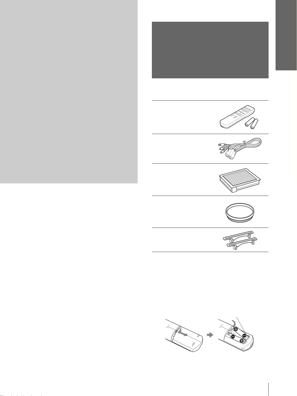
Unpacking
Check the carton to make sure it contains the
following items:
Remote control (1),
Size AA (R6)
batteries (2)
Signal interface
cable (1)
Air filter (for
replacement) (1)
Cinema filter (1)
Adjuster spacers (2)
AC power cord (1)
Operating Instructions (1)
Inserting the batteries into the remote
control
Insert the batteries E side first as sho wn
in the illustration.
Inserting them forcibly or with the
polarities reversed may cause a short
circuit and may generate heat.
Unpacking
5
GB
Page 6
Connections and
Preparations
Watching sports, etc. with your company
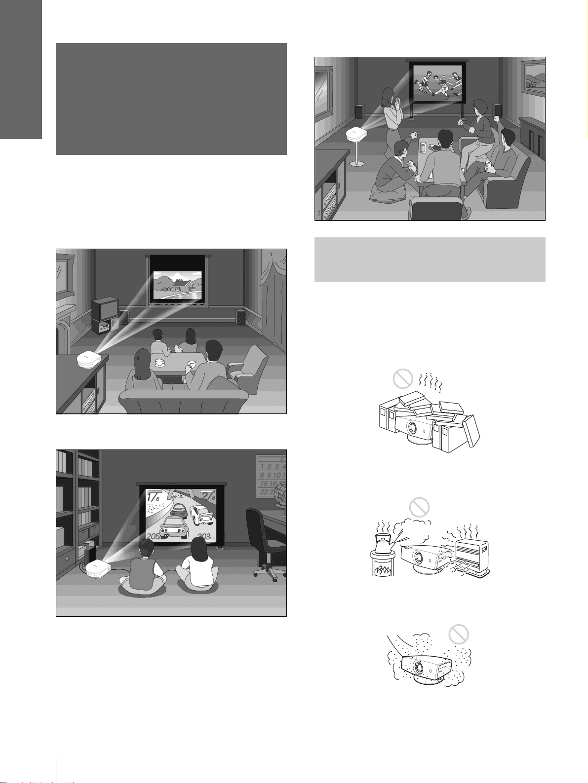
Step 1: Installing
the Projector
You can obtain good picture quality even when you
project the picture from the side of the screen (“Side
Shot”) (1 page 9). You can enjoy home
entertainment with this projector in vari ous situations .
Enjoying home theater
Before Setting Up the
Projector
Enjoying video games on a large screen
Do not place the projecto r in the follo wing si tuations,
which may cause malfunction or damage to the
projector.
Poorly ventilated
Highly heated and humid
GB
Step 1: Installing the Projector
6
Very dusty and ext remely smoky
Page 7
Connections and
Preparations
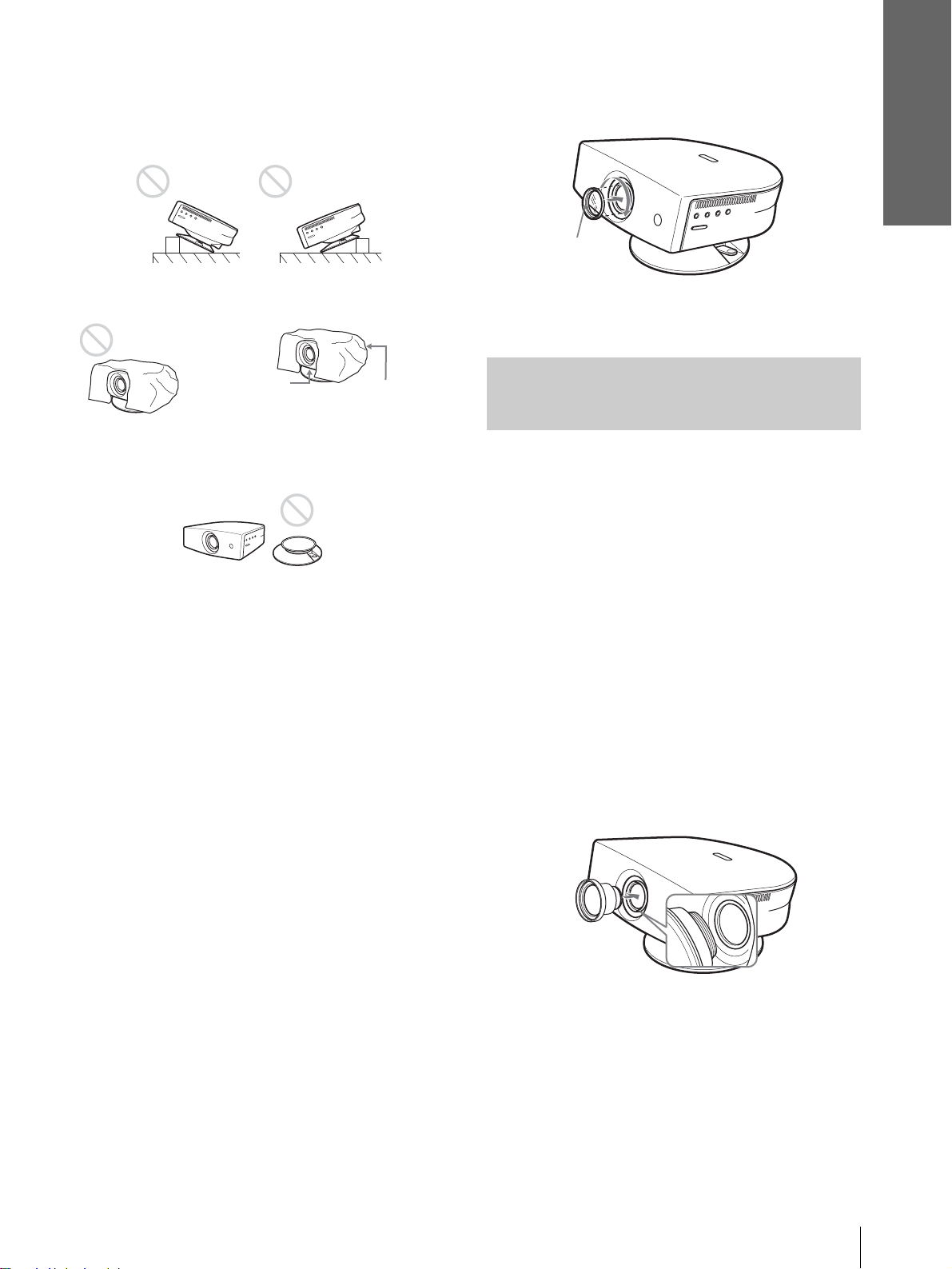
Do not use the projector under the following
conditions:
Tilting the unit extremely
Blocking the ventilation holes
Ventilation
holes
(exhaust)
Placing the projector withou t the adjuster
Ventilation
holes
(intake)
2 Insert the Cinema Filter, aligning i ts screw
with the thread around the projector’s
lens, then turn the Filter clockwise.
Cinema Filter
To remove the Cinema Filter, turn it
counterclockwise.
Using the Optional
Conversion Lens
You can install the optional VPLL-CW20 Short
Focused Conversion Lens on the projector. For
projection distances when installing the Conversion
Lens, see page 36.
Note
Installing the unit at altitudes
When using the projecto r at an al tit ude of 1,50 0 m or
higher, turn on high altitude mode in the INSTALL
SETTING menu. Failing to set thi s mode when us ing
the projector at high altitudes could have adverse
effects, such as reducing the reliability of certain
components.
Using the supplied Cinema Filter
The Cinema Filter is supplied with the projector,
allowing you to receive higher contrast color and
emphasized black color by attaching or removing.
Use it according to preference.
To attach the Cinema Filter
1 Turn off the power and disconnect the
power cord.
Follow the steps below to install the Conversion Lens.
For details o n installing the Lens, refer also to the
installation manual supplied with the Lens.
1 Turn off the power and disconnect the
power cord.
2 Remove the lens cap from the Conversi on
Lens.
3 Align the screw of the Con version Lens
with the thread around the lens of the
projector as illustrated below.
Step 1: Installing the Projector
7
GB
Page 8
Connections and
Preparations
4 Turn the Conversion Lens clockwise.
Notes on installation of the optional Conversion Lens
• The Lens scratches easily, so when handling it, always place it
gently on a stable and level surface in a horizontal position.
• Be sure not to bump the Lens on the surface of the lens of the
projector.
• Avoid touching the Lens surface.
To remove the installed Conversion Lens
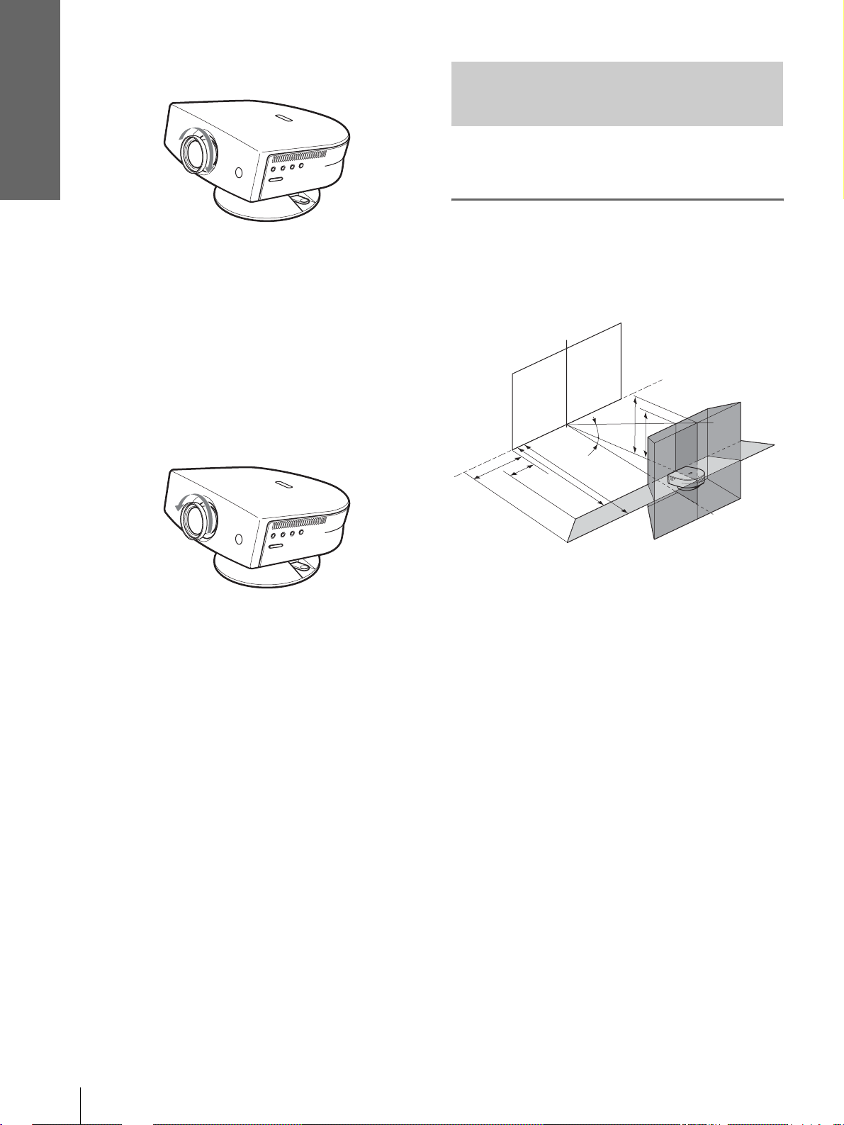
Installing the Pr ojector and a
Screen
The installation distance between the projector and
screen varies depending on the size of the screen.
1
Determine the installation
position of the projector and
screen.
Screen
Turn the installed Lens counterclockwise
until it can be removed.
Notes
• Be sure not to drop the uninstalled Conversion Lens.
• When you adjust pi cture distortion using “V Keystone” or
“Side Shot” in the INSTALL SETTING menu with the
optional Conversion Lens attached to the projector, the
aspect ratio of the original picture may not be correctly
displayed.
f
12˚
e
d
c
7˚
b
a
Projector
a: Minimum projection distance between the
screen and the center of the projector’s lens
when you place the projector on the side
(“Side Shot”), or when you place the
projector with the cent er of the screen and the
center of the lens aligned.
b: Maximum projection distance between the
screen and the center of the projector’s lens
when you place the projector on the side, or
when you place the projector wit h the cente r
of the screen and the center of the lens
aligned.
c: Maximum horizontal distance between the
right/left end of the screen and the center of
the projector’s lens when the projector is
placed on the side (when you use projection
distance a)
d: Maximum horizontal distance between the
right/left end of the screen and the center of
the lens when the projector is placed on the
side (when you use projection distance b)
e: Maximum vertical distance from the bottom
of the screen to the center of the projector’s
lens when you place the pro jector on the side
(when you use projection distance a)
GB
Step 1: Installing the Projector
8
Page 9
Connections and
Preparations
f: Maximum vertical distance from th e bottom
of the screen to the ce nter of the projector’s
lens when you place the pr ojector on the side
(when you use projection distance b)
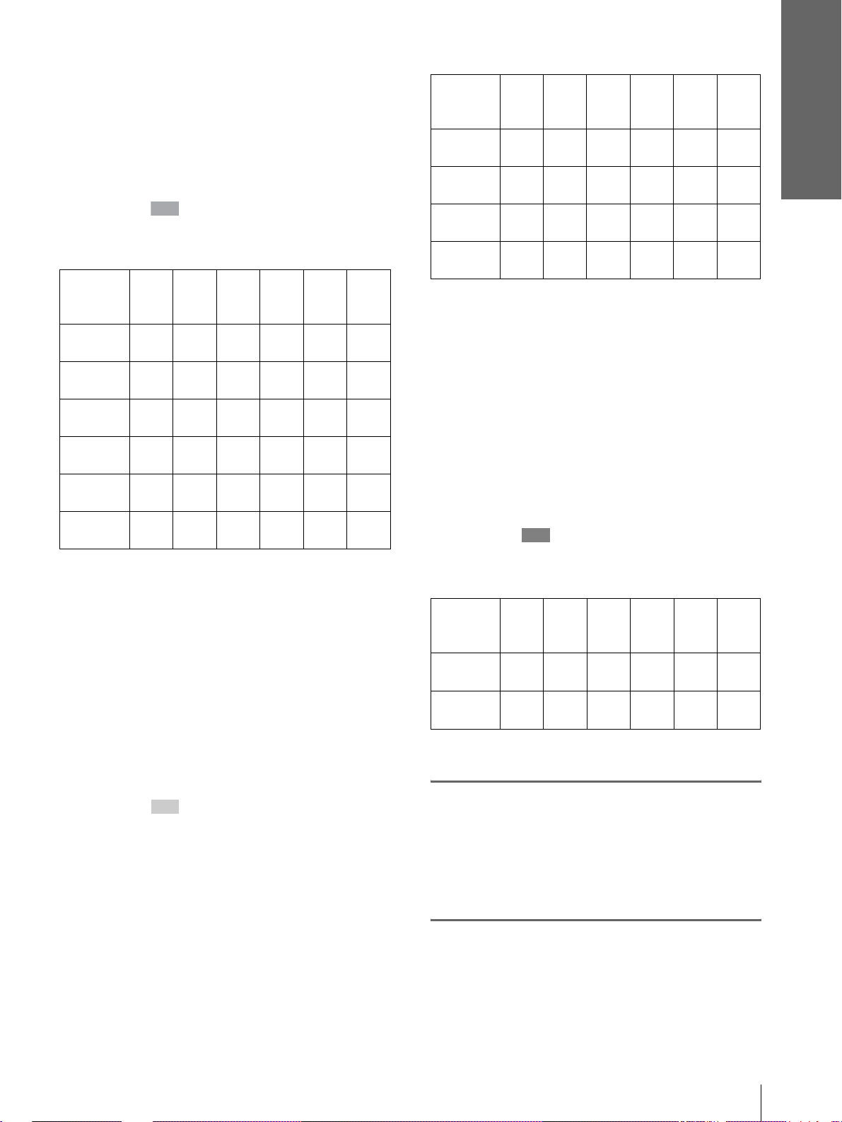
When projecting using both “Side Shot”
and “V Keystone” adjustments
Position the projector with the lens end within
the area in the illust ration, by using the
values a to f in the table below as a guide.
Unit: m (feet)
Screen
size
(inches)
a
b
c
d
e
f
Tip
The table shows the distances when projecting the
conventional video and 1080i format signals. Distances
used for projecting a 720p format signal and computer’s
signal are shown on page 34.
Note
When projecting with the optional Conversion Lens
attached, the values a, b, e and f are slightly different from
those in the table.
40 60 80 100 120 150
1.6
(5.2)
1.8
(5.9)
0.0
(0.0)
0.0
(0.0)
0.3
(1.0)
0.4
(1.6)
2.5
(8.2)
2.7
(8.9)
–0.1
(–0.3)
0.0
(0.0)
0.5
(2.0)
0.6
(2.0)
3.3
(10.8)
3.6
(11.8)
–0.2
(–0.6)
0.0
(0.0)
0.7
(2.3)
0.8
(2.6)
4.2
(13.8)
4.5
(14.8)
–0.2
(–0.6)
0.0
(0.0)
0.9
(3.0)
1.0
(3.3)
5.0
(16.4)
5.4
(17.7)
–0.3
(–1.0)
0.0
(0.0)
1.0
(3.3)
1.2
(3.9)
6.3
(20.7)
6.8
(22.3)
–0.3
(–1.0)
0.0
(0.0)
1.3
(4.3)
1.5
(4.9)
Unit: m (feet)
Screen
size
(inches)
a
b
c
d
Tip
The table shows the distances when proj ecting the video
signals. Dis tance s used for pr oject ing a 1080i/7 20p f ormat
signal and computer’s signal are shown on page 35.
Note
If you project the pi cture using “Side Shot” only, set “V
Keystone” in the INSTALL SETTING menu to “Manual,”
and adjust the level to “0.”
40 60 80 100 120 150
1.6
(5.2)
1.9
(6.2)
0.2
(0.7)
0.4
(1.3)
2.5
(8.2)
2.9
(9.5)
0.3
(1.0)
0.5
(1.6)
3.3
(10.8)
3.9
(12.8)
0.4
(1.3)
0.7
(2.3)
4.1
(13.5)
4.8
(15.7)
0.6
(2.0)
0.9
(3.0)
5.0
(16.4)
5.8
(19.0)
0.7
(2.3)
1.1
(3.6)
When projecting from the center
You can change the projection angle using the
adjuster. (1 page 13)
Position t he projector with the lens end within
the area in the illust ration, by using the
values a and b in the table below as a guide.
Unit: m (feet)
Screen
size
(inches)
a
b
40 60 80 100 120 150
1.6
(5.2)
1.9
(6.2)
2.4
(7.9)
2.9
(9.5)
3.2
(10.5)
3.9
(12.8)
4.0
(13.1)
4.8
(15.7)
4.8
(15.7)
5.8
(19.0)
6.2
(20.3)
7.3
(24.0)
0.8
(2.6)
1.4
(4.6)
6.0
(19.7)
7.3
(24.0)
When projecting using “Side Shot”
adjustment only
Position the projector with the lens end within
the area in the illust ration, by using the
values a, b, c a nd d in the table belo w as a guide.
2
Project an image on the screen
and adjust the picture so that it
fits the screen. (1 page 12)
T o project an image, connec t video equipment to
the projector. (1 page 10)
Step 1: Installing the Projector
9
GB
Page 10
Connections and
Preparations
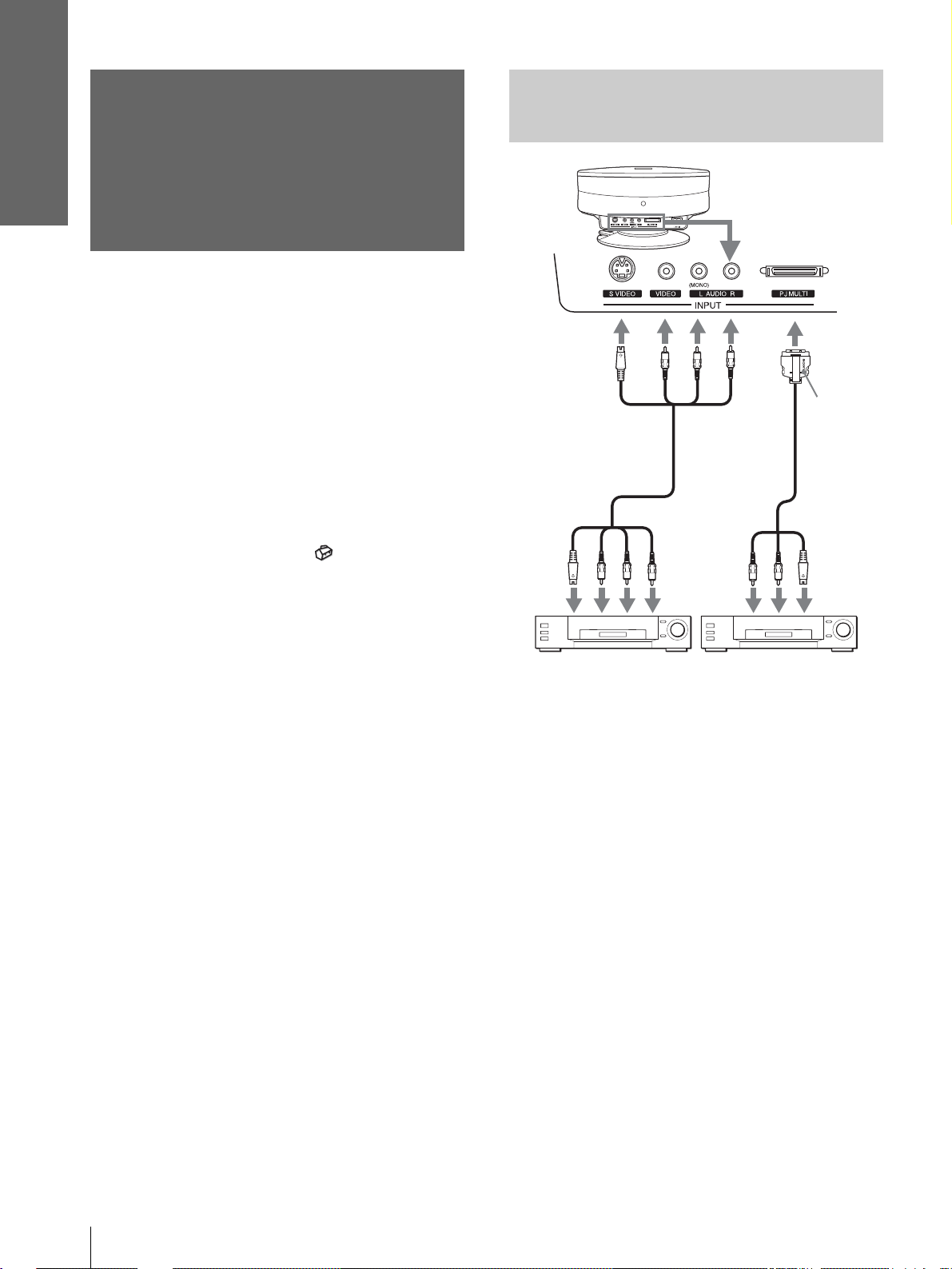
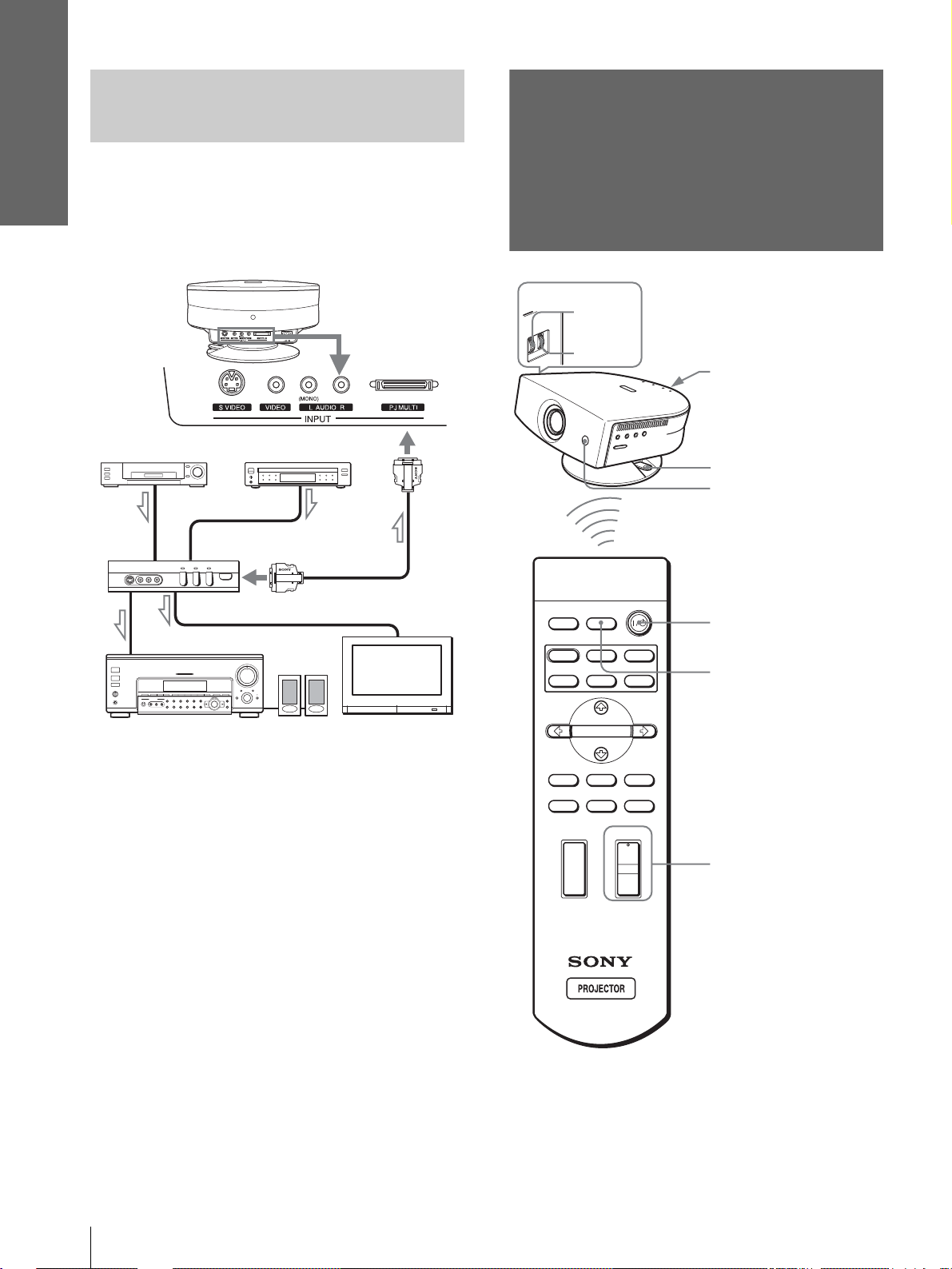
Step 2:
Connecting with Video
Equipment
Connecting the
Projector
When making connections, be sure to do the
following:
• Turn off all equipment before making any
connections.
• Use the proper cables for each connection.
• Insert the cable plugs properly; plugs that are not
fully inserted often generate noise. When pulling
out a cable, be sure to pull it out f rom the plug , not
the cable itself.
• Refer to the operat ing inst ructions of the co nnected
equipment.
• When you connect your projector to PJ MULTI,
select the input signal with the “In put-A Signal Sel. ”
setting in the SET SETTING menu. (1 page
27)
to S
video
or
video/
audio
output
S Video or
video/audio
cable (not
supplied)
Rear of the projecto r
Signal
interface
cable
(supplied)
to S video/
audio
output
with SONY
logo
upside
Video equipment
Video equipment
GB
10
Step 2: Connecting the Projector
Page 11
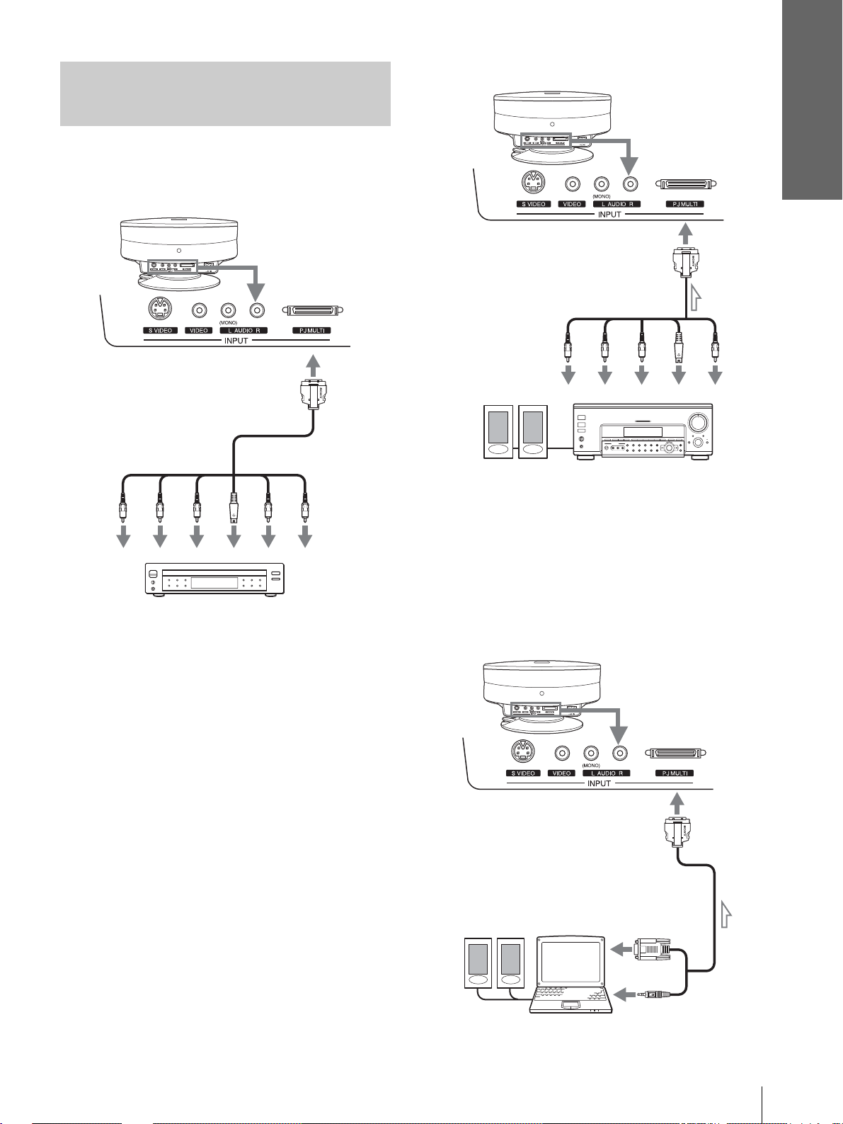
Connecting Using the Optional
Signal Interface Cables
To connect with a DVD player
equipped with the component video
connectors/digital tuner
Rear of the projector
Connections and
Preparations
Connecting an AV amplifier
Rear of the projector
Signal interface cable
(SIC-HS40, not supplied)
to S video or
video output
to component
video output
Signal interface cable
(SIC-HS20, not supplied)
to RGB/
component
output
PR/
B/
P
Y
C
B
DVD play er w ith com pone nt vid eo co nnec tors,
digital tuner, etc.
S
C
R
Video
Audio L
to S video/
audio
output
Audio R
YP
Active speakers
B/
B
C
AV amplifier
PR/
C
S
R
Video
Video
Connecting a Computer
To hear the sound from a computer, use the speakers
built in the comput er or connect the activ e speakers t o
the computer.
Note
Even if you connect the signal interface cable to the audio output
on the computer, there is no sound output from the project or.
Rear of the projector
Active
speakers
Signal interface cable
(SIC-HS30, not supplied)
to monitor
output
Computer
Step 2: Connecting the Projector
11
GB
Page 12
Connections and
Preparations
Connecting Using the
Optional Interfa ce Unit
Step 3: Adjusting
Using the optional interface unit allows you to
connect various video equipment, and to select the
output to the projector or TV from the connected
equipment simply by switching the select switch on
the interface unit.
Rear of the
projector
VCR, etc.
to PJ multi
output
DVD player, etc.
Interface unit
(IFU-HS1, not supplied)
PJ multi cable (supplie d
with the IFU-HS1)
the Picture Size
and Position
6
5,7
INPUTLIGHT
Rear remote control
detector
Ajuster lock lever
Front remote control
detector
2
STANDARD
USER 2
CINEMA
USER 3USER 1
4
DYNAMIC
PICTURE MODE
Audio amplifier
Active
speakers
TV
ENTER
DDE
MENUAPA
MUTING
+
–
RESET
6
WIDE MODE
VOLUME SIDE SHOT
+
–
Tip
The ? /
1 (on/standby), INPUT, MENU, and m/M/</,/
ENTER (joystick) buttons on the side panel of the projector have
the same functions as those on the remote control.
GB
12
Step 3: Adjusting the Picture Size and Position
Page 13
1
Plug the AC power cord into a
wall outlet.
The ON/STANDBY indicator lights in red and
the projector goes into standby mode.
ON/
STANDBY
2
Press the [/1 (on/standby)
Lights in red.
switch to turn on the projector.
The ON/STANDBY indicator lights in green.
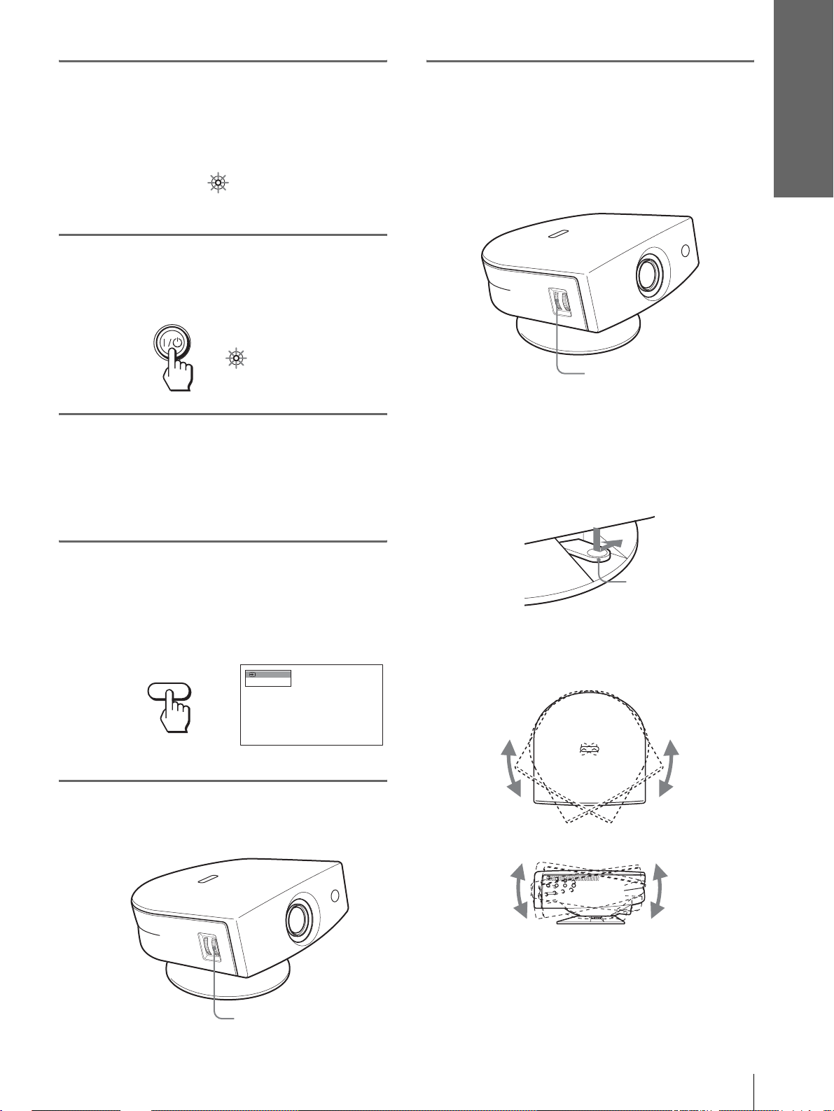
6
Adjust the size and position of
the picture to fit the screen
using the ZOOM ring and the
adjuster.
Turn the ZOOM ring to adjust the picture size.
Connections and
Preparations
ON/
Lights in green.
STANDBY
3
Turn on the equipment
connected to the projector.
Refer to the operating instructions of the
connected equipment.
4
Press INPUT to project the
picture on the screen.
Each time you press the button, the input
indication changes. (1 page 19)
Video 1
INPUT
NTSC 3.58
ZOOM ring
Adjusting the picture position using the
adjuster
Hold down and slide the adjuster lock lever to
the right, move the projector, then return the
lock lever.
Adjuster lock lever
You can move the projector horizontally or
vertically within the following ranges:
5
Adjust the focus r oughly using
the FOCUS ring.
FOCUS ring
Up to 30º each way horizontally
Up to 10º each way
vertically
Step 3: Adjusting the Picture Size and Position
13
GB
Page 14

Connections and
Preparations
Adjusting the picture position using the
supplied adjuster spacer
Attaching one of the supplied spacers for adjuster
adjustment (spacers for 1
º and 2°) allows you to tilt
the projector to the ri ght or left at a ti lting angl e up to
2
º.
Adjuster
spacer
(supplied)
Adjuster
spacer
(supplied)
To attach the supplied adjuster spacer
1 Place a thick cloth (e.g., a cushion) beneath the
projector. Place the projector face down.
2 While pressing the lock knobs inward, remo ve the
adjuster bar at the bottom of the adjuster table to
which you want to attach the supplied spacer.
When projecting using both “Side Shot” and
“V Keystone” adjustments
1 Use the adjuster to adjust the vertical
position.
If you set “V Keystone” in the INSTALL
SETTING menu to “Auto” (1 page 27), the
vertical distortion will be automatically corrected .
Note
The “V Keystone” adjustment may not correct trapezoidal
distortion perfe ctly , depending on the room temper ature or the
screen angle. In this case, adjust the distortion manually.
2 Adjust so that the left or right side of the
picture fits that of the screen.
If you position the proj ector on the lef t side of the
screen, adjust so th at the left si de of the pictur e fits
the left side of the screen. With the projector
positioned on the right side, adjust so t hat the right
side fits the right side of the screen.
At the same time, align the bottom side of the
picture with that of the screen.
Screen
Picture
3 Fit the spacer into the removed adjuster bar spot.
3 Adjust to correct horizontal trapezoidal
distortion using the SIDE SHOT + or –
button.
Press SIDE SHO T + or – so that the upper side of
the picture becomes parallel to the bottom side. If
the left side is longer than the right side, press
SIDE SHOT –.
SIDE SHOT
Press SIDE SHOT + if the right side i s longer . To fineadjust the distortion, press M or m.
GB
14
Step 3: Adjusting the Picture Size and Position
Page 15

Connections and
Preparations
When projecting using “Side Shot”
adjustment only
1 Set “V Keystone” in t he INST ALL SETTING
to “Manual,” and set the level to “0” (1
page 27) or press RESET.
2 Adjust so that the left or right side of the
picture fits that of the screen.
If you position the proj ector on the le ft sid e of th e
screen, adjust so t hat the left si de of the pictur e fits
the left side of the screen. With the projector
positioned on the ri ght side, adjust so that the right
side fits the right side of the screen.
At the same time, adjust the vertical size of the
aligned side of the picture to fit the screen using
the ZOOM ring.
Screen
Picture
Note
The V Keystone adjustment may not correct trapezoidal distortion
perfectly, depending on the room temperature or the screen angle.
In this case, adjust the distortion manually.
7
Turn the FOCUS ring to adjust
the focus again.
Tip
When you adjust distortion manually using “V Keystone”
and the SIDE SHOT buttons in steps 6 and 7, the built-in
test pattern is projected on the screen. If you want to make
adjustments using the current input signal, set “Test
Pattern” in the INSTALL SETTING menu to “Off.”
(1 page 27)
3 Adjust to correct horizontal trapezoidal
distortion using the SIDE SHOT + or –
button.
For how to correct, see step 3 in
projecting using both
Keystone
When projecting fr om th e center
Adjust so that both the position and size of
the bottom side of the picture fit those of the
bottom side of the screen using the adjuster
and the ZOOM ring.
If you set “V Keystone” in the INSTALL SETTING
menu to “Auto” (1 page 27), the vertical distortion
will be automatically corrected.
Picture
” adjustments.”
Screen
“Side Shot” and “V
“When
Step 3: Adjusting the Picture Size and Position
15
GB
Page 16

Connections and
Preparations
Step 4:
Selecting the
1
Plug the AC po wer cord into a
wall outlet.
The ON/STANDBY indicator lights in red and
the projector goes into standby mode.
Menu Language
You can select one of nine languages for displaying
the menu and other on-screen displays. The factory
default setting is Englis h.
INPUTLIGHT
STANDARD
DYNAMIC
PICTURE MODE
USER 2
ENTER
DDE
MUTING
WIDE MODE
VOLUME SIDE SHOT
+
+
CINEMA
USER 3USER 1
MENUAPA
RESET
2
4-6
3
ON/
STANDBY
2
Press the [/1 (on/standby)
Lights in red.
switch to turn on the pr ojector.
The ON/STANDBY indicator lights in green.
ON/
Lights in green.
STANDBY
3
Press MENU.
The menu appears.
The menu presently se lected is shown as a
yellow button.
PICTURE SETTING
Picture Mode:
Adjust Picture...
MENU
Volume: 30
Input A
–
Tip
You can operate the menu using the joystick on the side panel of
the projector instead of the M/m/</,/ENTER buttons on the
remote control.
–
4
Press M or m to select the
MENU SETTING menu, and
press , or ENTER .
The select ed menu appears.
:
:
:
:
or
ENTER
Input A
A
GB
16
Step 4: Selecting the Menu Language
Page 17

5
Press M or m to select
“Language”, and press , or
ENTER.
Connections and
Preparations
:
:
or
6
Press M or m to select a
ENTER
language, and press < or
ENTER.
The menu changes to the selected language.
Input A
:
:
To clear the menu
Press MENU.
or
ENTER
Step 4: Selecting the Menu Language
17
GB
Page 18

Projecting
Projecting the
This section describes how to operate the
projector to view the picture from the
equipment connected to the projector. It
also describes how to select the wide
screen mode or the quality of the picture to
suit your taste.
Picture on the
Screen
4
INPUTLIGHT
2
STANDARD
USER 2
ENTER
DDE
MUTING
+
CINEMA
USER 3USER 1
MENUAPA
RESET
MUTING button
DYNAMIC
PICTURE MODE
WIDE MODE
VOLUME SIDE SHOT
+
–
–
7
1
Plug the AC po wer cord into a
wall outlet.
The ON/STANDBY indicator lights in red and
the projector goes into standby mode.
ON/
Lights in red.
STANDBY
GB
18
Projecting the Picture on the Screen
Page 19

2
Press the [/1 (on/standby)
switch to turn on the projector.
The ON/STANDBY indicator lights in green.
ON/
STANDBY
3
Turn on the equipment
Lights in green.
connected to the projector.
Refer to the operating instructions of the
connected equipment.
4
Press INPUT repeatedly to
select the input you want to
project on the screen.
Display the indication of the input you want.
5
Turn the ZOOM ring to adjust
the size of the picture.
ZOOM ring
6
Turn the FOCUS ring to adjust
the focus.
Adjust to obtain sharp focus.
Projecting
Example:To view the picture from the video
equipment connected to the VIDEO
INPUT jack.
Video 1
INPUT
To view the picture from
Video equipment connected to
VIDEO INPUT on the projector
Video equipment connected to S
VIDEO INPUT on the projector
RGB/component equipment
connected to PJ MULTI INPUT via
the optional signal interface cable or
the interface unit
Video equipment connected to PJ
MUL TI INPUT via the optional signal
interface cable or the interface unit
Video equipment equipped with S
VIDEO connected to PJ MULT I
INPUT via the optional signal
interface cable or the interface unit
*
Set the “Input-A Signal Se l.” setting in the SET SETTING
menu according to the input signal . (1 page 27)
NTSC 3.58
Press INPUT to
display
Video 1
S-Video 1
*
Input-A
Video 2
S-Video 2
FOCUS ring
7
Press V OLUME + or – to adjust
the volume.
VOLUME
Projecting the Picture on the Screen
19
GB
Page 20

Cutting off the sound
Press MUTING on the remote
control.
To restore the sound, press MUTING again.
Selecting the Wide
Screen Mode
Projecting
To turn off the power
1 Press the [/1 (on/standby) switch.
A message “POWER OFF?” appears on the
screen.
2 Press the [/1 switch again.
The ON/ST ANDBY indicator flashes in green and
the fan contin ues to run to r educe the int ernal heat.
Also, the ON/ST ANDBY indicator flashes quickly
during which you will not be able to light up the
ON/STANDBY indicator with the [/1 switch.
3 Unplug the AC power cord from the wall
outlet after the fan stops running and the
ON/STANDBY indicator lights in red.
You can turn off the project or b y holdi ng the [/1 (on/
standby) switch for about one second, instead of
performing the above steps.
Y ou can en joy variou s wide screen mode according to
the video signal re ceived. You can also select it using
the menu. (1 page 26)
INPUTLIGHT
STANDARD
USER 2
ENTER
DDE
MUTING
CINEMA
USER 3USER 1
RESET
+
–
MENUAPA
WIDE MODE button
DYNAMIC
PICTURE MODE
WIDE MODE
VOLUME SIDE SHOT
+
–
GB
20
Press WIDE MODE.
Each time you press the button, you can select
the “Wide Mode” setting.
Selecting the Wide Screen Mode
Page 21

Full
A 16:9 squeezed picture is displayed with the
correct aspect ratio. A 4:3 picture is enlarged
horizontally to fit the 16:9 screen.
Subtitle
The subtitle area is compressed and displayed in
the lower part of the screen. Use this mode to
view a movie with subtitles.
Good-bye
Tip
Squeezed: An original 16:9 aspect ratio picture is recorded
horizontally compressed to a 4: 3 picture.
Normal
A picture with normal 4:3 aspect ratio is
displayed in the center of the screen to fil l the
vertical screen size.
Wide Zoom
A 4:3 aspect ratio picture is enlarged and the
upper and lower portions of the picture are
compressed to fit the 16:9 screen. Use this mode
to view news, variety shows, etc.
Zoom
A normal 4:3 aspect ratio picture is enlarged
vertically and horizontal ly in the same ra tio to
fill the 16:9 screen. This mode is ideal for
viewing a wide-format movie.
Full Through
One-to-one mapping is done on a squeeze d 16:9
picture. It is displayed in the center of the
screen.
Normal Through
One-to-one mapping is done on a 4:3 normal
aspect ratio picture. It is displayed i n th e center
of the screen.
Notes
• You can adjust the vertical position of the picture with
“V Position” in the INPUT SETTING menu when
“Zoom” or “Subtitle” is selected, or when “Full
Through” or “Normal Through” is selected for video
(50Hz) or progressive component (50p) input signal.
• You can adjust the position of the subtitles with “Title
Area” in the INPUT SETTING menu only when
“Subtitle” is selected.
• If “Full Through” or “Normal Through” is selected when
a video (50 Hz) or progressive vide o (50p) signal is
input, the picture may not be comple te ly disp la yed on
the screen due to the number of dots of the LCD panel.
Projecting
Notes on selecting the wide screen mode
• Select the wide screen mode taking into account
that changing the aspect rati o of the ori ginal picture
will provide a different look from that of the
original image.
• Note that if the projector is used for profit or for
public viewing, modifying the original picture by
switching to the wide mode may constitute an
infringement of the rights of authors or producers,
which are legally protected.
Selecting the Wide Screen Mode
21
GB
Page 22

Selecting the
Picture Viewing
Press one of the PICTURE
MODE buttons (DYNAMIC,
STANDARD, CINEMA and
USER 1, 2 and 3).
Projecting
Mode
You can select the picture viewing mode that best
suits the type of program or room condition.
INPUTLIGHT
STANDARD
USER 2
ENTER
DDE
MUTING
+
–
CINEMA
USER 3USER 1
MENUAPA
RESET
PICTURE MODE buttons
DYNAMIC
STANDARD
CINEMA
USER 1, 2 and 3
DYNAMIC
PICTURE MODE
WIDE MODE
VOLUME SIDE SHOT
+
–
DYNAMIC
Select for enhanced picture contrast and
sharpness.
STANDARD
Recommended for normal vie wi ng con dit ion in
your home.
Also select to reduce roughness when viewing
the picture with DYNAMIC.
CINEMA
Select for soft, film-like pictu re.
USER 1, 2 and 3
You can adjust the quality of the picture to suit
your taste and store t he settings in to the selected
memory of the projecto r . Press one of the USER
1, 2 and 3 buttons, then adjust the picture by
using the menus. The settings are stored, and
you can view the picture with the adjusted
picture quality by pre ssing t he b utto n. (1 page
25)
GB
22
Selecting the Picture Viewing Mode
Page 23

Display items
Using the
Menus
This section describes how to make
various adjustments and settings using the
menus.
Input signal indicator
Video 1
NTSC 3.58
Input signal setting indicator
Picture adjustment menu
Contrast: Min
Input signal indicator
Shows the selected input channel. is displayed
when no signal is input. You can hide this indicator
using “Status” in the MENU SETTING menu.
Input signal setting indicator
For Input-A: Shows “Computer,” “Component” or
“Video GBR.”
For V ideo/S V ideo input: Sho ws “ Auto” or the “Color
System” setting in the SET SETTING menu.
x
Using the Menus
Operation through
the Menus
The projector is equipped wi th an on-screen me nu for
making various adj ustment s and set ting s. The set ting
items are displayed in a pop-up menu or in a sub
menu. If you select an item name followed by dots
(...), a sub menu with setting items appear. You can
change the tone of the menu display and the menu
language displayed in the on-screen menu.
To change the menu language, see “Selecting the
Menu Language” on page 16.
INPUTLIGHT
STANDARD
DYNAMIC
PICTURE MODE
USER 2
ENTER
DDE
MUTING
WIDE MODE
VOLUME SIDE SHOT
+
–
+
–
CINEMA
USER 3USER 1
MENUAPA
RESET
2-4
1
Operation through the Menus
23
GB
Page 24

1
Press MENU.
The menu appears.
The menu presently selected is shown as a
yellow button.
SET SETTING
Smart APA: On
Auto Input Search:
Input-A Signal Sel.:
MENU
Color System: Auto
Power Saving: Off
Illumination: Off
Off
Computer
Input A
4
Make the setting or adjustment
on an item.
When changing the adjustment level
To increase the value, press M or ,.
T o decrease the value, press m or <.
Press ENTER to restore the original screen.
When changing the setting
Press M or m to change the setting.
Press < or ENTER to restore the original
screen.
2
Press M or m to select a men u,
and press , or ENTER.
To clear the menu
Press MENU.
The select ed menu appea rs.
Using the Menus
To reset items that have been
adjusted
3
Press M or m to select an item
you want to adjust and press
, or ENTER .
The setting items are displayed in a pop-up
menu or in a sub menu.
Pop-up menu
Menu Setting items
or
ENTER
Input A
Select the item you want to reset, then press RESET.
“Complete!” appears on the screen and the setting is
reset to its factory preset value.
Items that can be reset are:
• “Contrast,” “Brightness,” “Color,” “Hue,”
“Sharpness” and “RGB Enhancer” in “Adjust
Picture...” of the PICTURE SETTING menu
• “Dot Phase,” “H Size” and “Shift” in “Adjust
Signal...” of the INPUT SETTING menu
• “V Keystone” (when set to “Manual”) and “Side
Shot” of the INASTALL SETTING menu
GB
24
Operation through the Menus
Sub menu
Menu Setting items
Graphics
High
Input A
PICTURE SETTING
ADJUST PICTURE
Contrast: 80
Brightness: 50
RGB Enhancer: 30
Gamma Mode:
Color Temp:
Standard
Page 25

Menu Lists
Menu Configurations
The projector is equipped with six pages. The items
that can be adjusted in each menu are described on
page 25 to 27.
PICTURE SETTING menu
The PICTURE SETTING menu is used for adjusti ng
the picture. You can also adjust the volume.
INPUT SETTING menu
The INPUT SETTING menu is used to adjust the
input signal. You can adjust the size of the picture, and
select wide screen mode, etc.
SET SETTING menu
The SET SETTING menu is used for changing the
settings of the projector.
MENU SETTING menu
The MENU SETTING menu is used to change the onscreen language, disp lay position of the menu screen,
etc.
INSTALL SETTING menu
The INST ALL SETTI NG menu is used for cor recting
distortion of the picture.
INFORMATION menu
The INFORMATION menu is used to display the
horizontal and ve rtical freq uencies of the in put signal
and the used time of the lamp.
Menu Items
Adjustable items are limited according to the input
signals. Items that cannot be adjusted are not
displayed in the menu. (1 page 38)
PICTURE SETTING
Item Description
Picture Mode You can select picture viewing mode that
Volume Adjusts the volume.
Adjust Picture…
Contrast The higher the setting, the greater the
Brightness The higher the setting, the brighter the
Color The higher the setting, the greater the
Hue The higher the setting, the more greenish
Sharpness The higher the setting, the sharper the
RGB
Enhancer
best suits the type of picture or the
environment.
Dynamic: Select for enhanced picture
contrast and sharpness.
Standard: Recommended for normal
viewing condition. Also select to reduce
roughness when viewing the picture
with Dynamic.
Cinema: Select for soft, film-like picture.
User 1, 2 and 3: You can adjust the
quality of the picture to suit your taste
and store the settings. Once the settings
are stored, you can view the picture with
the adjusted picture quality by pressing
the PICTURE MODE button.
To store the settings
1 Select “User 1”, “User 2” or “User
3”.
2 Adjust the items you want in the
menus.
Items that can be stored are:
“Adjust Picture...” items other than
“Volume,” and “Wide Mode” setting
Tip
You can also adjust the picture quality
in “Dynamic”, “Standard” or “Cinema”
mode. To reset to the factory setting,
press RESET.
contrast. The lower the setting, the lower
the cotrast.
picture. The lower the setting, the darker
the picture.
intensity. The lower the setting, the lower
the intensity.
the picture becomes. The lower the
setting, the more purplish the picture
becomes.
picture. The lower the setting, the softer
the picture.
Adjusts the picture sharpness when
computer signals are input.
Using the Menus
Menu Lists
25
GB
Page 26

Item Description
Black Level
Adj (Adjust)
Emphasizes black color to produce a
bolder “dynamic” picture. Set according
to the input signal source.
High: Gives higher emphasis to the black
color.
Low: Gives lower emphasis to the black
color.
Off: Cancels this feature.
Gamma Mode Graphics: Reproduce s t he photos in
natural tones.
Text: Contrasts black and white. Suitable
for images that contain lots of text.
Color Temp. High: Gives the white colors a blue tint.
Middle: Gives the white colors a neutral
tint.
Low: Gives the white colors a red tint.
DDE
(Dynamic
Detail
Enhancer)
Off: Plays a video signal in an interlace
format without converting.
Progressive: Converts an interlace format
video signal to a progressive format .
Film: Normally, select this option.
Reproduces the 2-3 Pull-Down film
Using the Menus
sources with smoo th pic tu re mo v eme nt.
When the video signal with a format
other than the 2-3 Pull-Down is input,
“Progressive” is automatically selected.
Cinema Black Switches the lamp wattage during
projection.
On: Enhances the black by reducing the
lamp wattage.
Off: Normal wattage.
Tip
If “Cinema Bla ck” is set to “On,” the next time
the power is turned on, the lamp will use the
“Off” setting for the first time, and then go to
“On.”
INPUT SETTING
Item Description
Adjust Signal…
Item Description
Wide Mode You can select the 4:3 aspect ratio picture
mode, “Normal” and “Normal Through,”
and 16:9 aspect ratio picture mode,
“Full,” “W ide Zoom, ” “Zoom, ” “Subtitle”
and “Full Through.”
Full: The 16:9 squeezed* picture is
diplayed with the correct aspect. The
4:3 picture is e nlarged horizontally to
fit the 16:9 screen.
* squeezed: An original 16:9 aspect
ratio picture is recorded horizontally
compressed to be a 4:3 picture.
Normal: The picture with normal 4:3
aspect ratio is displayed to fill the
vertical screen size.
Wide Zoom: The picture with 4:3 aspect
ratio is enlarged and the upper and
lower portions of the picture are
compressed to fit the 16:9 screen. Use
this mode to view news, variety shows,
etc.
Zoom: The normal 4:3 aspect ratio
picture is enlarged verticall and
horizontally at the equal ratio to fill the
16:9 screen. The mode is ideal for
viewing a wide-format movie.
Subtitle: The subtitle area is compressed
and displayed at the lower part of the
screen. Use this mode to view a movie
with the subtitle.
Full Through: One-to-one mapping is
done on a squeezed 16:9 picture. It is
displayed in the center of the screen.
Normal Through: One-to-one mapping
is done on the picture with 4:3 aspect
ratio. It is displayed in the center of the
screen.
Note
If “Full Through” or “ N ormal Through” is
selected when a video (50 Hz) or progressive
video (50p) signal is input, the picture may not
be completely displayed on the screen due to the
number of dots of the LCD panel.
Dot Phase Adjusts the picture from a computer for
clearer picture after it is adjusted by
pressing the APA button.
H Size Adjusts the horizontal size of the picture
from a computer. The higher the setting,
the wider the picture. The lower the
setting, the narrower the picture.
Shift As the setting for H (horizontal)
increases, the picture moves to the right,
and as the setting decreases, the picture
moves to the left. Use < or , to adju st
the horizontal position.
As the setting for
V (vertical) increases,
the picture moves up, and as the setting
decreases, the picture moves down. Use
M or m to adjust the vertical position.
V Position Adjusts the vertical position of the picture
Title Area Adjusts the subtitle area. As the setting
For details, see “Selecting the Wide
Screen Mode” on page 20.
in wide screen mode. As the setting
increases, the picture moves up. As the
setting decreases, the picture moves
down.
Note
This item is adjustable only when “Zoom” or
“Subtitle” is selected, or when “Full Through”
or “Normal Thro ugh” is selected for video
(50Hz) or progressive component (50p) input
signal.
increases, the subtitle area moves up. As
the setting decreases, the subtitle area
moves down.
Note
This item is adjustable only when “Subtitle” is
selected.
GB
26
Menu Lists
Page 27

SET SETTING
Item Description
Smart APA With this item set to On, the APA function
Auto Input
Search
Input-A Signal
Sel.
Color System Select the color system of the input signal.
Power Saving When set to On, the POWER SAVING
Illumination Turns on the illumination on the top panel
works automatically for a signal input from
a computer so that the picture can be seen
clearly. You can also activate the APA
function by pressing the AP A bu tton on the
remote control.
Tip
The APA (Auto Pixel Alignment) automatically
adjusts the input signal from a computer so that
the picture can be seen clearly.
Set to On when an optional Interface Unit
such as the IFU-HS1 is connected to the PJ
MULTI connector on the projector.
Selects the signal input from the equipment
by selecting “Input-A” with the INPUT
button.
Computer: Inputs the signal from a
computer.
Component: Inputs the component or
progressive component signal from a
DVD player, digital tuner, etc.
Video GB R: Inputs the signal fro m a
digital tuner.
Auto: Selects the color system of the input
signal automatically from among NTSC,
PAL, SECAM, NTSC
PAL-N.
“NTSC3. 58”–“PAL-N”: Sets the color
system to the selected system manually.
indicator lights. The projector goes into
power saving mode if no signal is input for
10 minutes, and the lamp goes out and the
cooling fan keeps running. In power saving
mode, no button functions for the first 60
seconds. It is cancelled when a signal is
input or any b utt on is pres sed. If you do not
set the projector to power saving mode,
select Off.
of the projector when set to On. It turns off
when set to Off.
4.43, PAL-M or
INSTALL SETTING
Item Description
V Keystone Corrects the vertical trapezoidal distortion
Side Shot Corrects the horizo ntal trapezoidal
Image Flip Flips the picture on the screen horizontally
Background Selects the background color of the screen
Test Pattern When set to On, a test pattern is displayed
High Altitude
Mode
of the picture. ( )
Auto: Normally set to this postion.
Manual: Sets a lower value (– direction)
when the bottom of the trapezoid is
longer than the top. Sets a higher value
(+ direction) when the top of the
trapezoid is longer than the bottom. If
you project the picture using “Side
Shot” only, set to “Manual,” and adjust
the level to “0.”
Note
The “V Keystone” adjustment may not correct
the trapezoidal distortion perfectly, depending on
the room temperature or the screen angle. In this
case, adjust the di stortion manually.
distortion of the picture. ( )
Set the level to “0” when you adjust the
picture using “V Keystone” only.
and/or vertically.
Off: The picture does not flip.
HV: Flips the picture horizontally and
vertically.
H: Flips the picture horizontally.
V: Flips the picture vertically.
when no signal is input. You can select
“Black” or “Blue.”
on the screen when adjusting using “Side
Shot” or “V Keystone. ” I f yo u do not want
to display a test pattern, set to Off.
Off: Use this setting when using the
projector at normal altitudes.
On: Use this setting when using the
projector at an altitude of 1,500 m or
higher.
INFORMATION
Using the Menus
MENU SETTING
Item Description
Status Set to Off to turn off the on-screen
displays except for the menus, message
when turning off the power, and warning
messages.
Language Selects the la ng ua g e used in the menu an d
on-screen dis plays. Available languages
are: English, French, German, Italian,
Spanish, Portuguese, Japanese, Chinese
and Korean.
Menu Position Selects the display position from Top
Left, Bottom Left, Center, To p Right
and Bottom Right.
Menu Color Selects the tone of the menu display from
White or Black.
Item Description
fH Displays the horizontal frequency of the
input signal.
fV Displays the vertical frequency of the input
signal.
Lamp Timer Indicates how long the lamp has been
turned on.
Menu Lists
27
GB
Page 28

About the Preset Memory
Adjusting Picture Quality of
No.
This projector has 35 types of preset data for input
signals (the preset memory ). When the preset signal is
a Signal from the Computer
You can automatically adjust to obtain the clearest
picture when projecting a signal from the computer.
input, the projector automatically detects the signal
type and recalls th e data for the s ignal fr om the preset
memory to adjust it to an optimum picture. The
memory number and signal type of that signal are
displayed in the INFORMATION menu.
INFORMATION
fH: 48.47kHz
fV: 60.00Hz
No.23
1024x768
Lamp Timer: 0H
Input A
Memory No.
Signal type
Using the Menus
Y ou can als o adjust the preset da ta through the INPUT
SETTING menu.
This projector also has 20 types of user memori es for
Input-A into which you can save the setting of the
adjusted data for an unpreset input signal.
When an unpreset signal is input for the first time, a
memory number is displayed as 0. When you adjust
1 Project a still picture from the com puter.
2 Press the APA (Auto Pixel Alignment)
button.
When the picture is adjuste d properly, “complete”
appears on the screen.
Notes
• When “Smart APA” is set to “On,” the APA function is
automatically activated.
• Press the APA button when the image appears on the whole
display area of the computer. If there are black edges around the
image, the APA function will not function properly and the
image may extend beyond the screen.
• If you switch the input signal or re-connect a computer, press
the APA button again to get the suitable picture.
• To restore the original screen, press the APA button again
during the adjustment.
• The picture may no t be adjusted properly depending on the
types of input signals.
• Adjust the items in the INPUT SETTING menu when you
adjust the picture manually. (1 page 26)
the data of the s ig nal in th e I N PUT SETTI NG menu ,
it will be registered to the projector. If more than 20
user memories are registered, the newest mem ory
always overwrites the oldest one.
See the chart on page 39 to find if the signal is
registered to the preset memory.
GB
Since the data is recalled from the preset memory
about the following signals, you can use these preset
data by adjusting “H size.” Make fine adjustment by
adjusting “Shift.”
Signal Memory No. H size
Super Mac-2 23 1312
SGI-1 23 1320
Macintosh 19” 25 1328
Note
When the aspect ratio of input signal does not match the screen
size, a part of the screen is displayed in black.
28
Menu Lists
Page 29

Others
This section describes how to solve the
problems, how to replace a lamp and air
filter, etc.
Troubleshooting
Power
The power is not
turned on.
Picture
No picture. c Check that the proper
c Wait for about one minute
before turning on the power.
(1 page 20)
c Close the lamp cover securely.
(1 page 31)
c Close the air filter cover
securely. (1 page 32)
connections have been made.
(1 page 10)
c Select the input source correctly
using the INPUT button.
(1 page 19)
c Set the computer signal to output
from an external monitor.
c Set the computer signal to output
only to an external monitor.
The picture from the PJ
MULT I connector is
colored strange.
Color balance is
incorrect.
The picture is too dark. c Adjust the c ontr ast or brigh tness
The picture is not clear. c Adjust the focus with the
The picture flickers. c Adjust “Dot Phase” for “Adjust
Sound
No sound. c Check that connecting cables are
On-screen display
On-screen display does
not appear.
Remote control
The remote control
does not work.
c Select “Computer”,
“Component” or “Video GBR”
for “Input-A Signal Sel” in the
SET SETTING menu
according to the input signal.
(1 page 27)
c Adjust the picture in the “Adjust
Picture ...” of the PICTURE
SETTING menu
(1 page 25).
c Set “Color System” in the SET
SETTING menu to match
the color system being input.
(1 page 27)
in the “A djust Picture ...” of the
PICTURE SETTING menu
properly. (1 page 25)
FOCUS ring. (1 page 19)
c Condensation has occurred on
the lens. Leave the projector for
about two hours with the power
on.
Signal...” in the INPUT
SETTING menu properly.
(1 page 26)
c Press MUTING on the remote
control.
properly con nected. (1 page
10)
c Adjust “Volume” in the
PICTURE SETTING menu
(1 page 25), or press
VOLUME + on the remote
control.
c Press MUTING on the remote
control.
c Set “Status” in the MENU
SETTING menu to “On.”
(1 page 27)
c Batteries could be weak.
Replace with new batteries. (1
page 5)
c Insert the batteries with correct
polarities. (1 page 5)
Others
Troubleshooting
29
GB
Page 30

Indicators
The LAMP/COVER or TEMP/FAN indicator on the
control panel lig hts up or flashes if th ere is any trouble
with your projector.
LAMP/COVER Indicator
TEMP/FAN Indicator
LAMP/COVER
flashes.
LAMP/COVER
lights up.
TEMP/FAN
flashes.
TEMP/FAN
lights up.
LAMP/COVER
and TEMP/FAN
light up.
LAMP/
COVER
TEMP/
FAN
POWER
SAVING
ON/
STANDBY
c Attach the lamp cover or the air filter
cover securely. (1 pages 31 and 32)
c The lamp has reached the end of its
life. Replace the lamp. (1 page 31)
c The lamp becomes a high temperature.
Wait for one minute to cool down the
lamp and turn on the power again. (1
page 20)
c The fan is broken. Consult with
qualified Sony personnel.
c The internal temperature is unusually
high. Check to see if nothing is
blocking the ventilation holes.
c The electrical system breaks down.
Consult with qualified Sony
personnel.
Warning Messages
Use the list below to check the meaning of the
messages displayed on the screen.
High temp.!
Lamp off in 1
min.
Frequency is
out of range!
Please check
Input-A Signal
Sel.
Please replace
the LAMP.
Please replace
the filter.
c Turn off the power.
c Check to see if nothing is blocking the
ventilation holes.
c Input a signal that is within the
acceptable range of the frequency.
c Set the output signal on an external
monitor of the connected computer to
SVGA.
c Set “Input-A Signal Sel.” in the SET
SETTING menu to “Computer”
when RGB signal is input from the
computer. (1 page 27)
c It is time to replace the lamp. Replace
the lamp. (1 page 31)
c It is time to replace the air filter. Replace
the air filter. (1 page 32)
Caution Messages
Use the list below to check the meaning of the
messages displayed on the screen.
NO INPUT c No signal is input. Check connections.
(1 page 10)
Not applicable! c Press the appropriate button.
Others
GB
30
Troubleshooting
Page 31

Replacing the Lamp
The lamp used for the light source has a certain life.
When the lamp dims, the color bal ance of the pic ture
becomes st range, or “P lease replace the LAMP.”
appears on the scre en, the lamp is e xhausted . Replace
the lamp with a new one (not supplied).
Use LMP-H150 Projector Lamp as the replacement lamp.
When replacing the lamp after using the
projector
Turn off the projector, then unplug the power cord.
Wait for at least an hour for the lamp to cool
completely.
Caution
The lamp becomes a high temperature after t urning off the
projector with th e [/1 (on/standby) switch. If you touch the lamp,
you may scald your finger. When removing the lamp unit, make
sure it remains horizontal, then pull straight up. Do not tilt the
lamp unit. If you pull out the lamp unit whi le tilted and if the lamp
is broken, the pieces may scatter, causing injury.
2 Open the lamp cover by loosening the
screw with a Philips screwdriver.
3 Loosen the screw on the lamp unit with a
Philips screwdriver. Holding the handle,
pull the lamp unit straight up.
1 Hold down the adjuster lock lever, slide it
to the right, raise the rear o f the projector,
then return the adjuster lock lever. While
keeping the screw on the bottom of the
projector turned inward with a coin or a
slotted screwdriver, open the projector
cover with your hand.
Note
Be sure that the projector is stable.
4 Insert the new lamp all the way in until it is
securely in place. Tighten the screw, and
fold down the handle.
Others
5 Close the lamp cover and tighten the
screw.
Replacing the Lamp
31
GB
Page 32

6 While pushing the projector cover toward
you by holding both sides of the cover on
the lens side, close the cover until it clicks.
Replacing the Air Filter
2
The air filter should be replaced periodically. When
“Please replace the filter.” appears on the screen,
replace th e air filter immediately.
Notes
1
7 Connect the power cord and set the
projector to standby mode .
8 Press the following b uttons on the remote
control in the fol lowing or der for less than
five seconds each: RESET , <, ,, ENTER.
Notes
• Do not put your hands into the lamp replacement spot, and do
not allow any liquid or object to fall into it to avoid electrical
shock or fire.
• Be sure to use the LMP-H150 Projector Lamp for replacement.
If you use lamps oth e r than LMP-H150, a malfunction may
occur.
• Be sure to turn off the projector and unplug the power cord
before replacing the lamp.
• Replacing the air filter is very important to maintain the high
efficiency of the projector and to prevent a malfunction. When
the replacement message appears on the screen, replace the air
filter without delay.
• When removing the air filter from the projector, be care ful th at
no dust or object gets into the inside of the projector.
• Before replacing the air f ilter , turn of f the pro jector and unplu g
the powe r co r d .
1 Hold down the adjuster lock lever, slide it
to the right, raise the rear of the projector,
then return the adjuster lock lever. While
keeping the screw on the bottom of the
projector turned inward with a coin or a
slotted screwdriver, open the projector
cover with your hand.
Note
Be sure that the projector is stable.
2 Push the filter lock knob to remove the
filter cover.
Disposal of used projector lamp
As the materials used in this lamp are similar to those
Others
of a fluorescent lamp, you should dispose of a used
projector lamp in the sa me way as a fl uorescen t lamp.
GB
32
3 Remove the air filter from the filter holder
by holding the tab on the air filter.
Air filter
Filter holder
Replacing the Air Filter
Page 33

4 Insert the new air filter into the fil ter holder
with the white surface up, put the holder
face down, then replace it into the
projector.
5 Replace the filter cover.
6 While pushing the projector cover toward
you by holding both sides of the cover on
the lens side, close the cover until it clicks.
Specifications
System
Projection system
3 LCD panel s , 1 lens, projection
system
LCD panel 0.62-inch TFT LCD panel, 1,24 5,816
pixels (415,272 pixels × 3)
Lens 1.2 times zoom lens (manual)
f33.6–42mm/F1.85–2.2
Lamp 150 W UHP type
Projection picture size
Range: 40 to 150 inches (measured
diagonally)
Color system NTSC
Acceptable video signals
Acceptable computer signals
Speaker Monaural speaker system, 33 mm
3.58/PAL/SECAM/NTSC4.43/
PAL-M/PAL-N system, switched
automatically/manually
15 kHz RGB/component 50 / 60 Hz,
Progressive component 50/60 Hz,
DTV (480/60i, 575/50i, 480/60p,
575/50p, 720/60p, 720/50p, 1080/
60i, 1080/50i), 1080/24PsF,
Composite video, Y/C video
fH: 19 to 72 kHz
fV: 48 to 92 Hz
Maximum resolution XGA 1024
768, fV: 85 Hz
5
(1
/16 inches) diameter,
max. 2 W
× 1
×
Others
Input
Video input VIDEO: phono type
Composite video: 1 Vp-p± 2 dB
sync negative (75 ohms terminated)
S VIDEO: Y/C, mini DIN 4-pin type
(male)
Y (luminance): 1 Vp-p±2 dB sync
negative (75 ohms terminated)
C (chrominance): burst 0.286 Vp-p
±2 dB (NTSC)
(75 ohms terminated)
burst 0.3 Vp-p±2 dB (PAL)
(75 ohms terminated)
PJ MULTI 32-pin multi connector
Composite video: 1 Vp-p±2 dB sync
negative (75 ohms terminated)
S video: Y/C
Y (luminance): 1 Vp-p±2 dB sync
negative (75 ohms terminated)
Specifications
33
GB
Page 34

C (chrominance): burst 0.286
Vp-p±2 dB (NTSC) (75 ohms
terminated)
burst 0.3 Vp-p±2 dB (PAL) (75
ohms terminated)
Analog RGB/component:
R/C
R (PR): 0.7 Vp-p±2 dB
(75 ohms terminated)
G: 0.7 Vp-p±2 dB
(75 ohms terminated)
G with sync/Y: 1 Vp-p±2 dB sync
negative (75 ohms terminated)
B/C
B (PB): 0.7 Vp-p±2 dB
Optional accessories
Signal interface unit IFU-HS1
Projector Lamp LMP-H150 (for replacement)
Air filter PK-HS1FL (for replacement)
Signal interface cables SIC-HS10/SIC-HS20/SIC-HS30/
SIC-HS40
Projection lens Short Focused Conversion Lens
VPLL-CW20
Projection Distances for a 1080i/720p
format signal and computer’s signal
(75 ohms terminated)
SYNC/HD: Composite sync input:
Screen
1–5 Vp-p high impedance, p ositiv e/
negative
Horizontal sync input: 1–5 Vp-p
high impedance, positive/negative
VD: Vertical sync input: 1–5
Vp-p high impedance, positive/
negative
General
Dimensions 304 × 168 × 321 mm
(12
Mass Approx. 4.5 kg (9 lb 15 oz)
× 6
5
/8 × 12
3
/4 inches) (w/h/d)
d
c
b
a
f
12˚
7˚
Projector
e
Power requirements
AC 100 to 240 V, 2.1–1.1 A,
50/60 Hz
Power consumption
Max. 200 W
When projecting using both “Sid e Shot ” and
“V Keystone” adjustments
For a 720p format signal and computer’s signal
(Standby mode: 3 W)
Operating temperature
0ºC to 35ºC (32ºF to 95ºF)
Others
Operating humidity
35% to 85% (no co ndensation)
Storage temperature
–20ºC to 60ºC (–4ºF to 140ºF)
Storage humidity 10% to 90%
Supplied accessories
Remote control RM-PJHS2 (1)
Size AA (R6) batteries (2)
Signal interface cable SIC-HS50
(5 m) (1)
AC power cord (1)
Air filter (for replacement) (1)
Cinema Filter (1)
Adjuster specers (2)
Operating Instructions (1)
Screen
size
(inches)
a
b
c
d
e
f
40 60 80 100 120 150
1.6
(5.2)
1.8
(5.9)
–0.2
(–0.7)
–0.2
(–0.7)
0.3
(1.0)
0.4
(1.3)
2.5
(7.9)
2.7
(8.9)
–0.3
(–1.0)
–0.3
(–1.0)
0.5
(1.6)
0.6
(2.0)
3.3
(10.8)
3.6
(11.8)
–0.4
(–1.3)
–0.3
(–1.0)
0.7
(2.3)
0.8
(2.6)
4.1
(13.5)
4.5
(14.8)
–0.6
(–2.0)
–0.4
(–1.3)
0.9
(3.0)
1.0
(3.3)
Unit: m (feet)
5.0
(16.4)
(17.7)
(–2.3)
(–1.6)
5.4
–0.7
–0.5
1.0
(3.3)
1.2
(3.9)
(20.3)
(22.3)
–0.8
(–2.6)
–0.6
(–2.0)
(4.3)
(4.9)
6.2
6.8
1.3
1.5
GB
Design and specifications are subject to change
without notice.
34
Specifications
Page 35

When projecting using “Side Shot”
adjustment only
For a 1080i/720p format signal and computer’s signal
Unit: m (feet)
Screen
size
(inches)
a
b
c
d
40 60 80 100 120 150
1.6
(5.2)
1.9
(6.2)
0.08
(0.2)
0.2
(0.7)
2.5
(8.2)
2.9
(9.5)
0.1
(0.3)
0.3
(1.0)
3.3
(10.8)
3.9
(12.7)
0.2
(0.7)
0.4
(1.3)
4.1
(13.5)
4.8
(15.7)
0.2
(0.6)
0.5
(1.6)
5.0
(16.4)
5.8
(19.0)
0.3
(1.0)
0.6
(2.0)
(20.3)
(24.0)
(1.0)
(2.6)
6.2
7.3
0.3
0.8
Others
Specifications
35
GB
Page 36

Projection Distances When Installing the Optional Conversion Lens
Floor installation example
Wall
Center of the screen
x
a: Distance between the screen and the center of the lens
b: Distance from the floor to the center of the lens
c: Distance from the floor to the bottom of the projector
x: Free
Distance from the front of the
cabinet to the center of the
lens
Center of the lens
Standard lens: 23 mm
(29/32 inches)
b
c
a
Floor
When using the VPLL-CW20 Short Focused Conversion Lens
Use the 40 to 150-inch screens.
For 16:9 aspect ratio screens
SS (inches) 40 60 80 100 120 150
Minimum
a
Others
Maximum
b
c
To calculate the installation measurements (SS: Screen size)
a (minimum) = SS × 29.7451
a (maximum) = SS × 36.30012 – 47.7234
b = x – (SS/4.84269158)
c = x – (SS/4.84269158 + 97)
1140
(45)
1400
(55
x-194
(x-7
x-291
(x-11
1
/8)
5
/8)
1
– 48.0584
/2)
1740
5
(68
/8)
2130
(83 7/8)
x-290
(x-11 1/2)
x-387
(x-15 1/4)
2330
(91 3/4)
2860
(112 5/8)
x-387
(x-15 1/4)
x-484
(x-19 1/8)
2930
(115 3/8)
3580
(141)
x-484
(x-19 1/8)
x-581
(x-22 7/8)
Unit: mm (inches)
3520
(138 5/8)
4310
(169 3/4)
x-581
(x-22 7/8)
x-678
(x-26 3/4)
4410
(173 3/4)
5400
(212 5/8)
x-726
(x-28 5/8)
x-823
(x-32 1/2)
GB
36
Specifications
Page 37

For 4:3 aspect ratio screens Unit: mm (inches)
SS (inches) 40 60 80 100 120 150
Minimum
a
Maximum
b
c
To calculate the installatio n measurements (SS: Screen size)
a (minimum) = SS × 29.7451 – 48.0584
a (maximum) = SS × 36.3 00 12 – 47.7234
b = x – (SS/5.92666667)
c = x – (SS/5.92666667 + 97)
1410
(55
1730
(68
x-237
(x-9
x-334
(x-13
5
/8)
1
/8)
3
/8)
1
/4)
2140
(84 3/8)
2620
(103 1/4)
x-356
(x-14)
x-453
(x-17 7/8)
2860
(112 7/8)
3510
(138 1/4)
x-474
(x-18 3/4)
x-571
(x-22 1/2)
3590
(141 3/8)
4390
(172 7/8)
x-593
(x-23 3/8)
x-690
(x-27 1/4)
4320
(170 1/8)
5280
(208)
x-711
(x-28)
x-808
(x-31 7/8)
5410
(213 1/8)
6620
(260 3/4)
x-889
(x-35)
x-986
(x-38 7/8)
Others
Specifications
37
GB
Page 38

Warning on power connection
Use a proper power cord for your local power supply.
The United States,
Canada
Plug type YP-11 YP-21 SP-61 B8 YP-13
Female end YC-13L YC-13L YC-13L C7-2 YC-13L
Cord type SPT-2 H03VVH2-F H03VVH2-F H03VVH2-F VCTFK
Rated Voltage & Current 10A/125V 2.5A/25 0V 2.5A/250V 2.5A/2 50V 7A/125V
Safety approval UL/CSA VDE BS SAA DENANHO
Cord length (max.) 4.5 m – – – –
Continental
Europe
UK Australlia Japan
Input signals and adjustable/setting items
Some of the items in the menus cannot be adjusted depending on the input signal. The following tables indicate
them.
The items that cannot be adjusted are not displayed in the menu.
Adjust Picture... menu
Item
Contrast zzzz
Brightness zzzz
Color z (except for B & W) zz –
Hue z (NTSC
Sharpness zzz–
RGB Enhancer – – – z
Black Level Adj zzz–
Gamma Mode – – – z
Color Temp zzzz
Others
DDE zz (15k only) z (15k only) –
Cinema Black zzzz
Volume zzzz
Video or S video (Y/C) Component Video GBR Computer
3.58/4.43 only,
except for B & W)
Input signal
zz–
GB
z : Adjustab le/can be set
– : Not adjustable/cannot be set
INPUT SETTING menu
Input signal
Item
Dot Phase – – – z
H size – – (except for 15k) – (exc ept for 15k) z
Shift – z (except fo r 15k) z (except for 15k) z
Wide Mo de zz
z : Adjustab le/can be set
– : Not adjustable/cannot be set
38
Specifications
Video or S
video (Y/C)
Component Video GBR Computer
z
(except for preset memory
numbers 5, 45, 49 and 50 of
DTV)
(except for preset memory
numbers 5, 45, 49 and 50
of HDTV)
–
Page 39
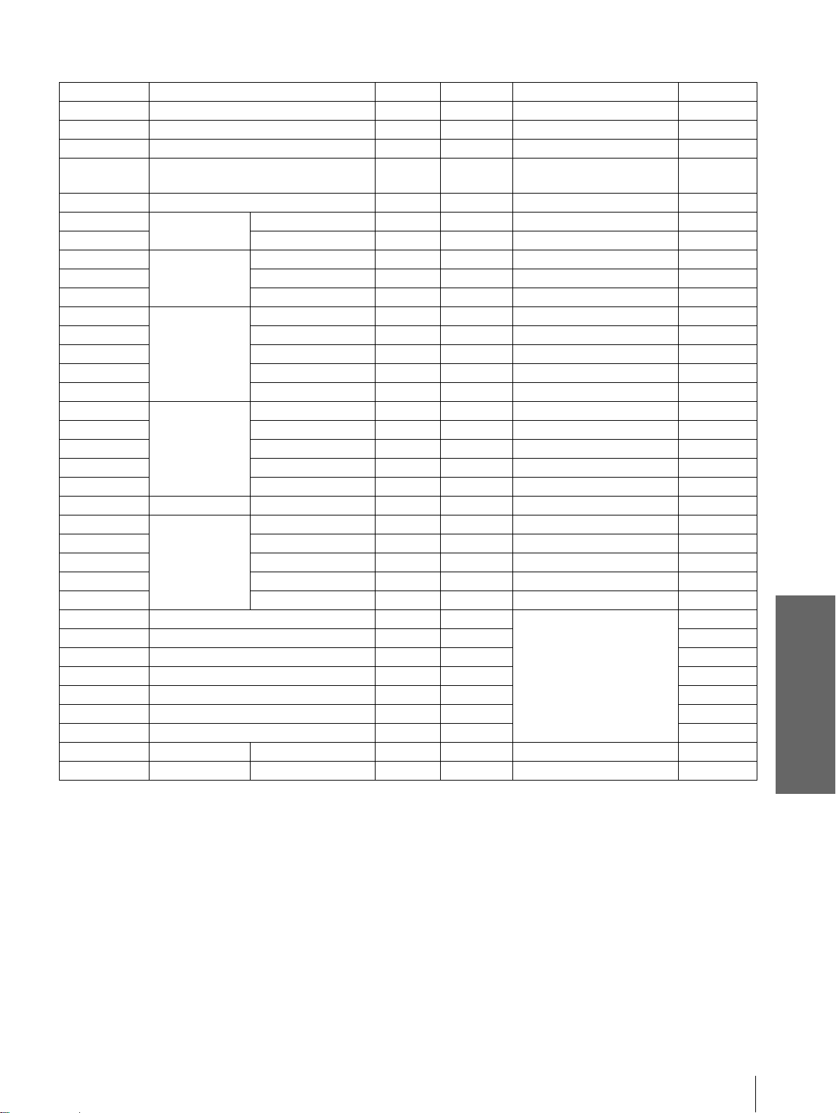
Preset Signals
Memory No. Preset signal fH (kHz) fV (Hz) Sync H size
1 Video 60 Hz 15.734 59.940 –– ––
2 Video 50 Hz 15.625 50.000 –– ––
3 480/60i (DTV) 15.734 59.940 SonG /Y or Composite Sync ––
4 575/50i (DTV) 15.625 50.000 SonG/Y or Composite sync/
Composite video
5 1080/60i (DTV), 1035/60i, 1080/60i 33.750 60.000 SonG/Y ––
6640
7 VGA VESA 85Hz 37.861 85.080 H-pos, V-neg 832
8640
9 VGA mode 2 31.469 70.086 H-neg, V-pos 800
10 VGA VESA 85Hz 37.861 85.080 H-neg, V-pos 832
11 640
12 Macintosh 13” 35.000 66.667 H - neg, V-neg 864
13 VGA VESA 72Hz 37.861 72.809 SonG 832
14 VGA VESA 75H z 37.500 75.000 H-neg, V- neg 8 40
15 VGA VESA 85H z 43.269 85.008 H-neg, V- neg 8 32
16 800
17 SVGA VESA 60Hz 37.879 60.317 H-pos, V-pos 1056
18 SVGA VESA 72Hz 48.077 72.188 H-pos, V-pos 1040
19 SVGA VESA 75Hz 46.875 75.000 H-pos, V-pos 1056
20 SVGA VESA 85Hz 53.674 85.061 H-pos, V-pos 1048
21 832
22 1024
23 XGA VESA 60Hz 48.363 60.004 H-neg, V-neg 1344
24 XGA VESA 70Hz 56.476 70.069 H-neg, V-neg 1328
25 XGA VESA 75Hz 60.023 75.029 H-pos, V-pos 1312
26 XGA VESA 85Hz 68.677 84.997 H-pos, V-pos 1376
43 480/60p (Progressive component) 31.470 60.000
44 575/50p (Progressive component) 31.250 50.000 ––
45 1080/50i (DTV) 28.130 50.000 ––
47 720/60p (DTV) 45.000 60.000 ––
48 720/50p (DTV) 37.500 50.000 ––
49 1080/24 (DTV), 1080/48i 27.000 48.000 ––
50 540/60p 33.750 60.000 ––
51 1366
71 854
× 350 VGA mode 1 31.469 70.086 H-pos, V-neg 800
× 400 PC-9801 Nor m al 24.823 56.416 H-neg, V-neg 848
× 480 VGA mode 3 31.469 59.940 H-neg, V-neg 800
× 600 SVGA VESA 56Hz 35.156 56.250 H-pos, V-pos 1024
× 624 Macint o sh 16 ” 49.724 74.550 H-neg, V-neg 1152
× 768 XGA VESA 43Hz 35.522 43.479 H-pos, V-pos 1264
SonG/Y
× 768 Special 56 Hz 45.000 56.000 H-neg, V-neg 1766
× 480 Spe cial 56 Hz 30.110 56.150 H-neg, V-neg 1046
––
––
Others
Notes
• When a signal other than the preset signals shown above is input, the picture may not appear properly.
• Memory No. 22 shows the interlace signal.
Specifications
39
GB
Page 40

Location of Controls
Front
You can use the buttons on the control panel with the same names as those on the remote control to operate the
projector.
ON/STANDBY indicator
(1 page 13)
POWER SAVING indicator
(1 page 27)
TEMP/FAN indicator
(1 page 30)
LAMP/COVER indicator
(1 page 30)
LAMP/
COVER
TEMP/
INPUT
MENU
POWER
SAVING
ON/
STANDBY
FAN
SIDE SHOT
+ –
[/1 (on/standby) switch
(1 page 13)
INPUT button (1 page 13)
MENU button (1 page 16)
Joystick (1 page 16)
SIDE SHOT +/– b utton (1 page 14)
Others
Lens
GB
40
Front remote contro l
detector (1 page 12)
Ventilation hole s
(exhaust) (1 page 7)
Location of Controls
Adjuster lock lever
(1 page 13)
Page 41

Rear
Air filter cover
(1 page 32)
Lamp cover
(1 page 31)
Rear remote control
detector (1 page 12)
Speaker
FOCUS ring
(1 page 13)
ZOOM ring
(1 page 13)
Adjuster
(1 page 13)
S VIDEO INPUT connector
(mini DIN 4-pin)/VIDEO
INPUT jack (phono type)
(1 page 10)
AUDIO L/R INPUT jacks
(phono type)
(1 page 10)
~ AC IN socket
PJ MULTI INPUT
connector (32-pin multi)
(1 page 11)
Others
Location of Controls
41
GB
Page 42

Remote Control
INPUT button (1 page 13)
Infrared transmitter
LIGHT button
Illuminates the buttons on the
remote control.
PICTURE MODE buttons
(1 page 22)
DYNAMIC
INPUTLIGHT
STANDARD
PICTURE MODE
USER 2
CINEMA
USER 3USER 1
[/1 (on/standby) switch
(1 page 13)
DDE button (1 page 26)
The button has the same function as
“DDE” in the PICTURE SETTING menu.
APA button (1 page 28)
WIDE MODE button (1 page 20)
VOLUME +/– button
(1 page 19)
WIDE MODE
ENTER
DDE
MUTING
MENUAPA
RESET
VOLUME SIDE SHOT
M/m/</,/ENTER buttons
(1 page 23)
MENU button (1 page 23)
RESET button (1 page 24)
MUTING button (1 page 20)
SIDE SHOT +/– button
(1 page 14)
Others
GB
42
Location of Controls
Page 43

Index
A
Adjust Picture…............................... 25
Adjusting
focus
............................................. 13
picture size and position
the picture
zoom
Air filter
............................. 25, 28
...................................... 13, 19
............................................. 32
B
Black Level Adj (Adjust)............... 26
Brightness
.......................................... 25
C
Cinema Black................................... 26
Color
.................................................. 25
Color System
Color Temp.
Connections
AV amplifier
computer
DVD player equipped with the
component video connectors/
digital tuner
using the optional
interface unit
video equipment
Contrast
.................................... 27
...................................... 26
............................... 11
..................................... 11
.............................. 11
............................ 12
.............................................. 25
D
DDE (Dynamic Detail
Enhancer)
Dot Phase
........................................ 26
.......................................... 26
F
fH........................................................ 27
fV
........................................................ 27
G
Gamma Mode................................... 26
H
........... 12
........................ 10
I
Image Flip.......................................... 27
Indicator
LAMP/COVER
TEMP/FAN
INFORMATION menu
INPUT SETTING menu
Input-A Signal Sel.
INSTALL SETTING menu
Installing the Projector and
a Screen
............................................. 8
.......................... 30
................................. 30
................... 27
................. 26
.......................... 27
............ 27
L
Lamp replacement............................ 31
Lamp Timer
Language
Location of controls
front
rear
remote control
....................................... 27
........................................... 27
.............................................. 40
................................................ 41
............................. 42
M
Menu
clearing the menu display
operation
reset
Menu Color
Menu Position
MENU SETTING menu
Message
caution
warning
...................................... 23
.............................................. 24
....................................... 27
................................... 27
.......................................... 30
........................................ 30
......... 24
................. 27
O
Optional accesories.......................... 34
P
Picture Mode..................................... 25
Cinema
Dynamic
Standard
User 1, 2 and 3
PICTURE SETTING menu
Power Saving
Preset memory
Projection
......................................... 25
...................................... 25
....................................... 25
............................ 25
............ 25
.................................... 27
............................ 28, 39
........................................... 18
R
Remote control
inserting the batteries
location of controls
Remote control detector
front
.............................................. 12
................................................ 12
rear
RGB Enhancer
.................................. 25
................... 5
.................... 42
S
Screen size........................................... 8
Selecting the menu language
SET SETTING menu
Sharpness
Shift
Side Shot
Specifications
Status
Supplied accessories
........................................... 25
..................................................... 26
........................................ 9, 27
.................................... 33
.................................................. 27
.......................... 5
.......... 16
....................... 27
T
Troubleshooting................................ 29
V
V Keystone.................................... 9, 27
Ventilation holes
exhaust
intake
Volume
........................................... 7
.............................................. 7
................................................ 19
W
WIDE MODE ................................... 20
Wide Mode
........................................ 26
Others
H Size................................................. 26
Hue
..................................................... 25
Index
43
GB
 Loading...