

Page 1
Video Projector VPL-HS2
4-092-536-12 (1)
Video Projector
Operating Instructions __________________________________
Mode d’emploi ______________ ___ _______________________
Manual de instrucciones _________________________________
GB
FR
ES
VPL-HS2
© 2002 Sony Corporation
Page 2
WARNING
To prevent fire or shock hazard, do not expose
the unit to rain or moisture.
To avoid electrical shock, do not open the
cabinet. Ref er servic ing to qual ified pers onnel
only.
This symbol is intended to alert the user to
the presence of uninsulated "dangerous
voltage" within the product's enclosure
that may be of sufficient magnitude to
constitute a risk of electric shock to
persons.
This equipment has been tested and found to comply
with the limits for a Class B digital device, pursuant to
Part 15 of the FCC Rules. These limits are designed to
provide reasonable protection against harmful
interference in a residential installation. This equipment
generates, uses, and can radiate radio frequency energy
and, if not installed and used in accordance with the
instructions, may cause harmful interference to radio
communications. However, there is no guarantee that
interferen ce wi ll n ot occu r in a par tic ular ins tal la tion. I f
this equipment doe s cause harmful in terf erenc e to radio
or television reception, which can be determined by
turning the equipment of f and on, the user is encouraged
to try to correct the interference by one or more of the
following measures:
- Reorient or relocate the receiving antenna.
- Increase the separation between the equipment and
receiver.
- Connect the equipment into an outlet on a circuit
different from that to which the receiver is connected.
- Consult the dealer or an experienced radio/TV
technician for help.
Y ou are cautioned th at any changes or modifi cations not
expressly approved in this manual could void your
authority to operate this equipment.
This symbol is intended to alert the user to
the presence of important operating and
maintenance (servicing) instructions in
the literature accompanying the
appliance.
For the customers in the USA
If you have any questions about this product, you may
contact:
Sony Electronics Inc.
Attn: Business Information Center (BIC)
12451 Gateway Boulevard
Ft. Myers, Florida 33913
Telephone No.: 800-686-7669
The number below is for FCC related matters only.
Declaration of Conformity
Trade Name: SONY
Model No.: VPL-HS2
Responsible Party: Sony Electronics Inc.
Address: 680 Kinderkamack Road, Oradell
NJ 07649 U.S.A.
Telephone No.: 201-930-6972
This device complies with Part 15 of the FCC Rules.
Operation is subject to the following two conditions: (1)
This device may not cause harmful interference, and (2)
this device must accept any interference received,
including interference that may cause undesired
operation.
For the customers in Canada
This Class B digital apparatus complies with Canadian
ICES-003.
Voor de kl anten in Nederland
Dit apparaat bev a t een vast ingebouwde batter ij die ni et
vervangen h oeft te wo rden tijdens de lev ensduur v an het
apparaat.
Raadpleeg uw leverancier indien de batterij toch
vervangen moet worden. De batterij mag alleen
vervangen worden door vakbekwaam servicepersoneel.
Gooi de batterij niet weg maar lever deze in als klein
chemisch afval (KCA).
Lever het apparaat aan het einde van de levensduur in
voor recycling, de batterij zal dan op correcte wijze
verwerkt worden.
The socket-outlet should be installed near the
equipment and be easily accessible.
GB
2
Page 3

Table of Contents
Using the Menus
Operation through the Menus ..............23
Menu Lists .............................................25
Menu Configurations .......................................25
Menu Items ......................................................25
About the Preset Memory No. .........................28
Precautions .............................................4
Connections and Preparations
Unpacking ...............................................5
Step 1: Installing the Projector ..............6
Before Setting Up the Projector .........................6
Using the Optional Conversion Lens .................7
Installing the Projector and a Screen ..................8
Step 2: Connecting the Projector ........10
Connecting with Video Equipment ..................10
Connecting Using the Optional Signal
Interface Cables ................................................11
Connecting Using the Optional
Interface Unit ....................................................12
Step 3: Adjusting the Picture Size and
Position .................................................. 12
Adjusting Picture Quality of a Signal
from the Computer ...........................................28
Others
Troubleshooting .......................................29
Replacing the Lamp ......................... ........31
Replacing the Air Filter ............................32
Specifications ...........................................33
Location of Controls ................................40
Front .................................................................40
Rear .................................................................. 41
Remote Control ................................................42
Index ..........................................................43
Step 4: Selecting the Menu
Language ............................................... 16
Projecting
Projecting the Picture on the Screen ..18
Selecting the Wide Screen Mode ........20
Selecting the Picture Viewing Mode ...22
3
GB
Page 4

Precautions
On safety
• Check that the operating voltage of your unit is
identical with the voltage of your local power
supply.
• Should any liquid or solid object fall into the
cabinet, unplug the unit and have it checked by
qualified personnel before operating it further.
• Unplug the unit from the wa ll outlet if it is not to be
used for several days.
• To disconnect the cord, pull it out by the plug. Never
pull the cord itself.
• The wall outlet should be near the unit and easily
accessible.
• The unit is not di sconnected to th e AC p ower source
(mains) as long as it is c onnect ed to t he wa ll ou tl et,
even if the unit itself has been turned off.
• Do not look into the lens while the lamp is on.
• Do not place your hand or objects near the
ventilation holes. The air coming out is hot.
On preventing internal heat build-up
After you turn off the power with the I / 1 (on/
standby) switch, do not disconnect the unit from the
wall outlet while the cooling fan is still running.
Caution
The projector is equipped with ventilation holes
(intake) and v entilatio n holes (exha ust). Do not block
or place anything near these holes, or internal heat
build-up may occur, causing picture degradation or
damage to the projector.
On repacking
Save the original shipping carton and packing
material; the y wil l c o me in handy if you ever hav e t o
ship your unit. Fo r maximum protect ion, repack your
unit as it was originally packed at the factory.
GB
4
Precautions
Page 5
Connections and
Preparations
Connections
and
Preparations
This section describes how to install the
projector and screen, how to connect the
equipment from which you want to project
the picture, etc.
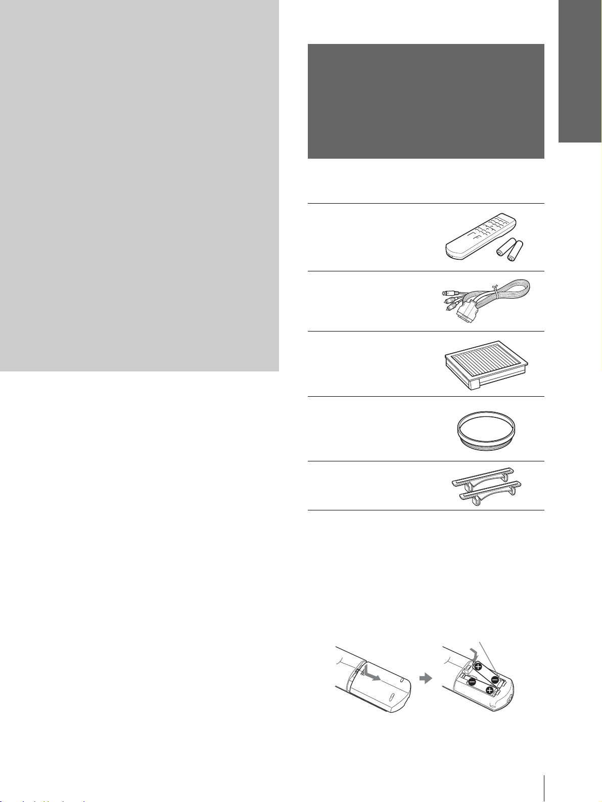
Unpacking
Check the carton to make sure it contains the
following items:
Remote control (1),
Size AA (R6)
batteries (2)
Signal interface
cable (1)
Air filter (for
replacement) (1)
Cinema filter (1)
Adjuster spacers (2)
AC power cord (1)
Operating Instructions (1)
Inserting the batteries into the remote
control
Insert the batteries E side first as sho wn
in the illustration.
Inserting them forcibly or with the
polarities reversed may cause a short
circuit and may generate heat.
Unpacking
5
GB
Page 6
Connections and
Preparations
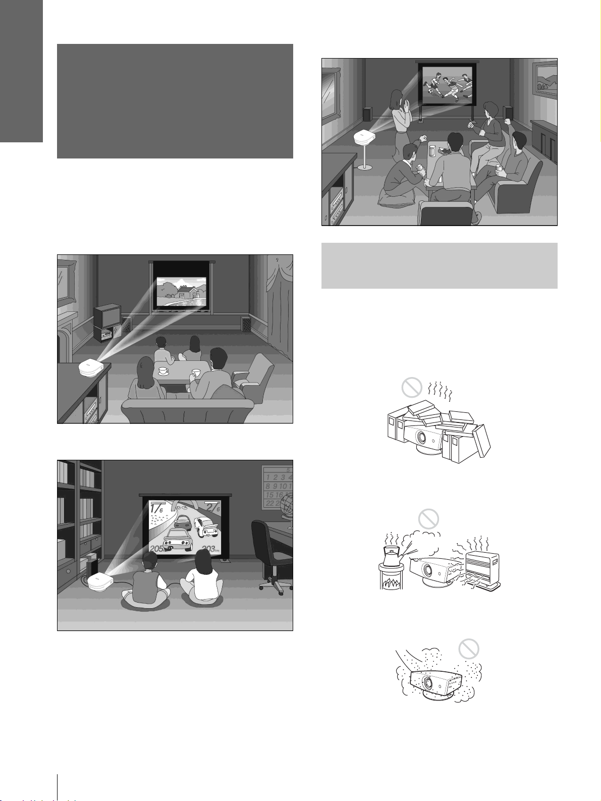
Watching sports, etc. with your company
Step 1: Installing
the Projector
You can obtain good picture quality even when you
project the picture from the side of the screen (“Side
Shot”) (1 page 9). You can enjoy home
entertainment with this projector in vari ous situations .
Enjoying home theater
Before Setting Up the
Projector
Enjoying video games on a large screen
Do not place the projecto r in the follo wing si tuations,
which may cause malfunction or damage to the
projector.
Poorly ventilated
Highly heated and humid
GB
Step 1: Installing the Projector
6
Very dusty and ext remely smoky
Page 7
Connections and
Preparations
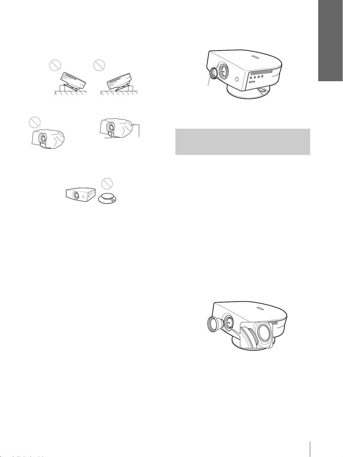
Do not use the projector under the following
conditions:
Tilting the unit extremely
Blocking the ventilation holes
Ventilation
holes
(exhaust)
Placing the projector withou t the adjuster
Ventilation
holes
(intake)
2 Insert the Cinema Filter, aligning i ts screw
with the thread around the projector’s
lens, then turn the Filter clockwise.
Cinema Filter
To remove the Cinema Filter, turn it
counterclockwise.
Using the Optional
Conversion Lens
You can install the optional VPLL-CW20 Short
Focused Conversion Lens on the projector. For
projection distances when installing the Conversion
Lens, see page 36.
Note
Installing the unit at altitudes
When using the projecto r at an al tit ude of 1,50 0 m or
higher, turn on high altitude mode in the INSTALL
SETTING menu. Failing to set thi s mode when us ing
the projector at high altitudes could have adverse
effects, such as reducing the reliability of certain
components.
Using the supplied Cinema Filter
The Cinema Filter is supplied with the projector,
allowing you to receive higher contrast color and
emphasized black color by attaching or removing.
Use it according to preference.
To attach the Cinema Filter
1 Turn off the power and disconnect the
power cord.
Follow the steps below to install the Conversion Lens.
For details o n installing the Lens, refer also to the
installation manual supplied with the Lens.
1 Turn off the power and disconnect the
power cord.
2 Remove the lens cap from the Conversi on
Lens.
3 Align the screw of the Con version Lens
with the thread around the lens of the
projector as illustrated below.
Step 1: Installing the Projector
7
GB
Page 8
Connections and
Preparations
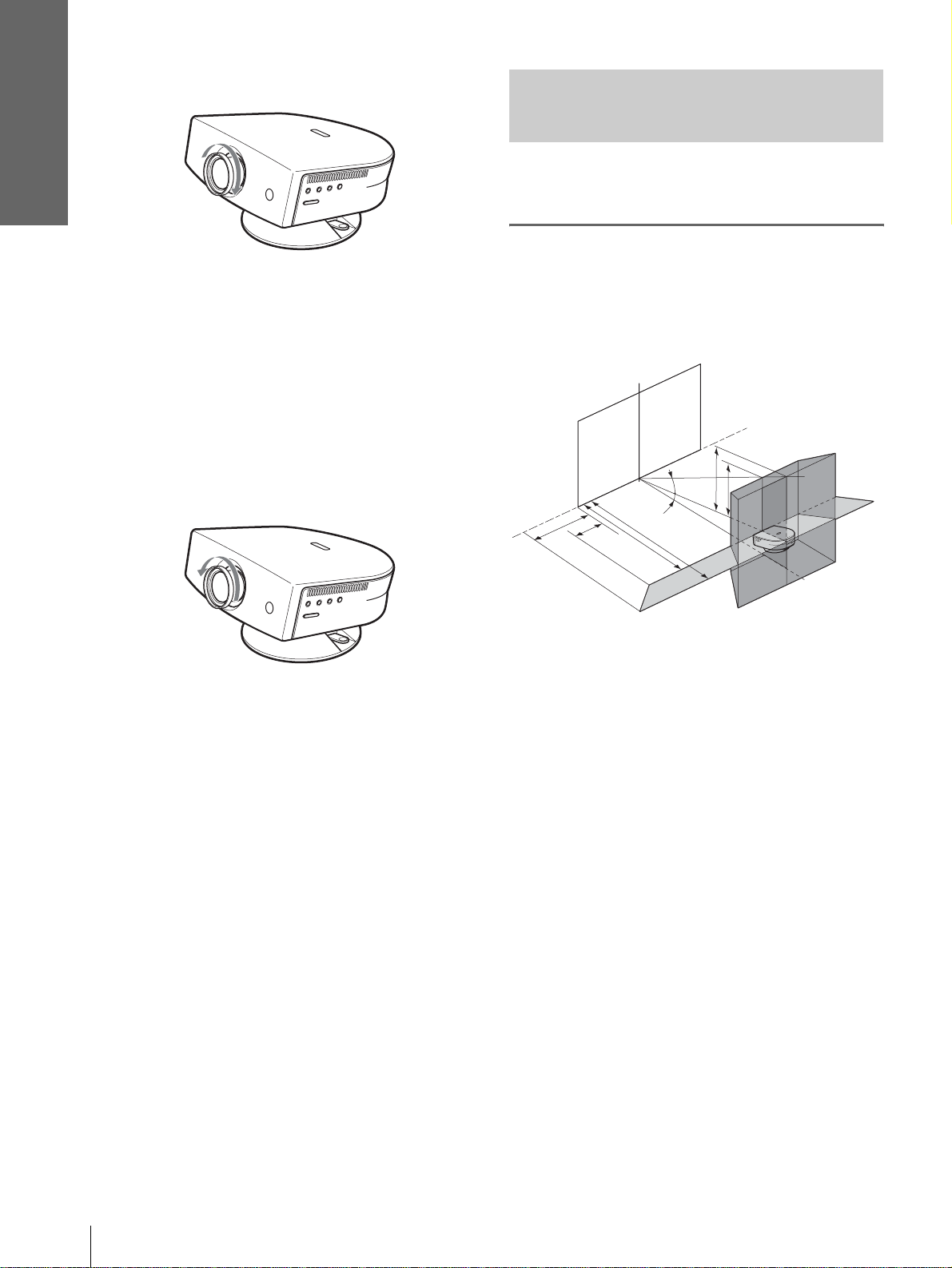
4 Turn the Conversion Lens clockwise.
Notes on installation of the optional Conversion Lens
• The Lens scratches easily, so when handling it, always place it
gently on a stable and level surface in a horizontal position.
• Be sure not to bump the Lens on the surface of the lens of the
projector.
• Avoid touching the Lens surface.
To remove the installed Conversion Lens
Installing the Pr ojector and a
Screen
The installation distance between the projector and
screen varies depending on the size of the screen.
1
Determine the installation
position of the projector and
screen.
Screen
Turn the installed Lens counterclockwise
until it can be removed.
Notes
• Be sure not to drop the uninstalled Conversion Lens.
• When you adjust pi cture distortion using “V Keystone” or
“Side Shot” in the INSTALL SETTING menu with the
optional Conversion Lens attached to the projector, the
aspect ratio of the original picture may not be correctly
displayed.
f
12˚
e
d
c
7˚
b
a
Projector
a: Minimum projection distance between the
screen and the center of the projector’s lens
when you place the projector on the side
(“Side Shot”), or when you place the
projector with the cent er of the screen and the
center of the lens aligned.
b: Maximum projection distance between the
screen and the center of the projector’s lens
when you place the projector on the side, or
when you place the projector wit h the cente r
of the screen and the center of the lens
aligned.
c: Maximum horizontal distance between the
right/left end of the screen and the center of
the projector’s lens when the projector is
placed on the side (when you use projection
distance a)
d: Maximum horizontal distance between the
right/left end of the screen and the center of
the lens when the projector is placed on the
side (when you use projection distance b)
e: Maximum vertical distance from the bottom
of the screen to the center of the projector’s
lens when you place the pro jector on the side
(when you use projection distance a)
GB
Step 1: Installing the Projector
8
Page 9
Connections and
Preparations
f: Maximum vertical distance from th e bottom
of the screen to the ce nter of the projector’s
lens when you place the pr ojector on the side
(when you use projection distance b)
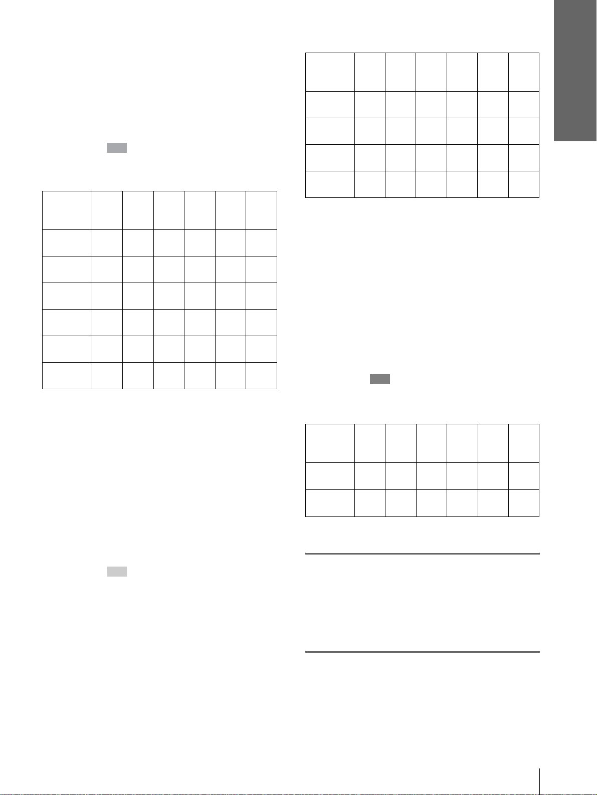
When projecting using both “Side Shot”
and “V Keystone” adjustments
Position the projector with the lens end within
the area in the illust ration, by using the
values a to f in the table below as a guide.
Unit: m (feet)
Screen
size
(inches)
a
b
c
d
e
f
Tip
The table shows the distances when projecting the
conventional video and 1080i format signals. Distances
used for projecting a 720p format signal and computer’s
signal are shown on page 34.
Note
When projecting with the optional Conversion Lens
attached, the values a, b, e and f are slightly different from
those in the table.
40 60 80 100 120 150
1.6
(5.2)
1.8
(5.9)
0.0
(0.0)
0.0
(0.0)
0.3
(1.0)
0.4
(1.6)
2.5
(8.2)
2.7
(8.9)
–0.1
(–0.3)
0.0
(0.0)
0.5
(2.0)
0.6
(2.0)
3.3
(10.8)
3.6
(11.8)
–0.2
(–0.6)
0.0
(0.0)
0.7
(2.3)
0.8
(2.6)
4.2
(13.8)
4.5
(14.8)
–0.2
(–0.6)
0.0
(0.0)
0.9
(3.0)
1.0
(3.3)
5.0
(16.4)
5.4
(17.7)
–0.3
(–1.0)
0.0
(0.0)
1.0
(3.3)
1.2
(3.9)
6.3
(20.7)
6.8
(22.3)
–0.3
(–1.0)
0.0
(0.0)
1.3
(4.3)
1.5
(4.9)
Unit: m (feet)
Screen
size
(inches)
a
b
c
d
Tip
The table shows the distances when proj ecting the video
signals. Dis tance s used for pr oject ing a 1080i/7 20p f ormat
signal and computer’s signal are shown on page 35.
Note
If you project the pi cture using “Side Shot” only, set “V
Keystone” in the INSTALL SETTING menu to “Manual,”
and adjust the level to “0.”
40 60 80 100 120 150
1.6
(5.2)
1.9
(6.2)
0.2
(0.7)
0.4
(1.3)
2.5
(8.2)
2.9
(9.5)
0.3
(1.0)
0.5
(1.6)
3.3
(10.8)
3.9
(12.8)
0.4
(1.3)
0.7
(2.3)
4.1
(13.5)
4.8
(15.7)
0.6
(2.0)
0.9
(3.0)
5.0
(16.4)
5.8
(19.0)
0.7
(2.3)
1.1
(3.6)
When projecting from the center
You can change the projection angle using the
adjuster. (1 page 13)
Position t he projector with the lens end within
the area in the illust ration, by using the
values a and b in the table below as a guide.
Unit: m (feet)
Screen
size
(inches)
a
b
40 60 80 100 120 150
1.6
(5.2)
1.9
(6.2)
2.4
(7.9)
2.9
(9.5)
3.2
(10.5)
3.9
(12.8)
4.0
(13.1)
4.8
(15.7)
4.8
(15.7)
5.8
(19.0)
6.2
(20.3)
7.3
(24.0)
0.8
(2.6)
1.4
(4.6)
6.0
(19.7)
7.3
(24.0)
When projecting using “Side Shot”
adjustment only
Position the projector with the lens end within
the area in the illust ration, by using the
values a, b, c a nd d in the table belo w as a guide.
2
Project an image on the screen
and adjust the picture so that it
fits the screen. (1 page 12)
T o project an image, connec t video equipment to
the projector. (1 page 10)
Step 1: Installing the Projector
9
GB
Page 10
Connections and
Preparations
Step 2:
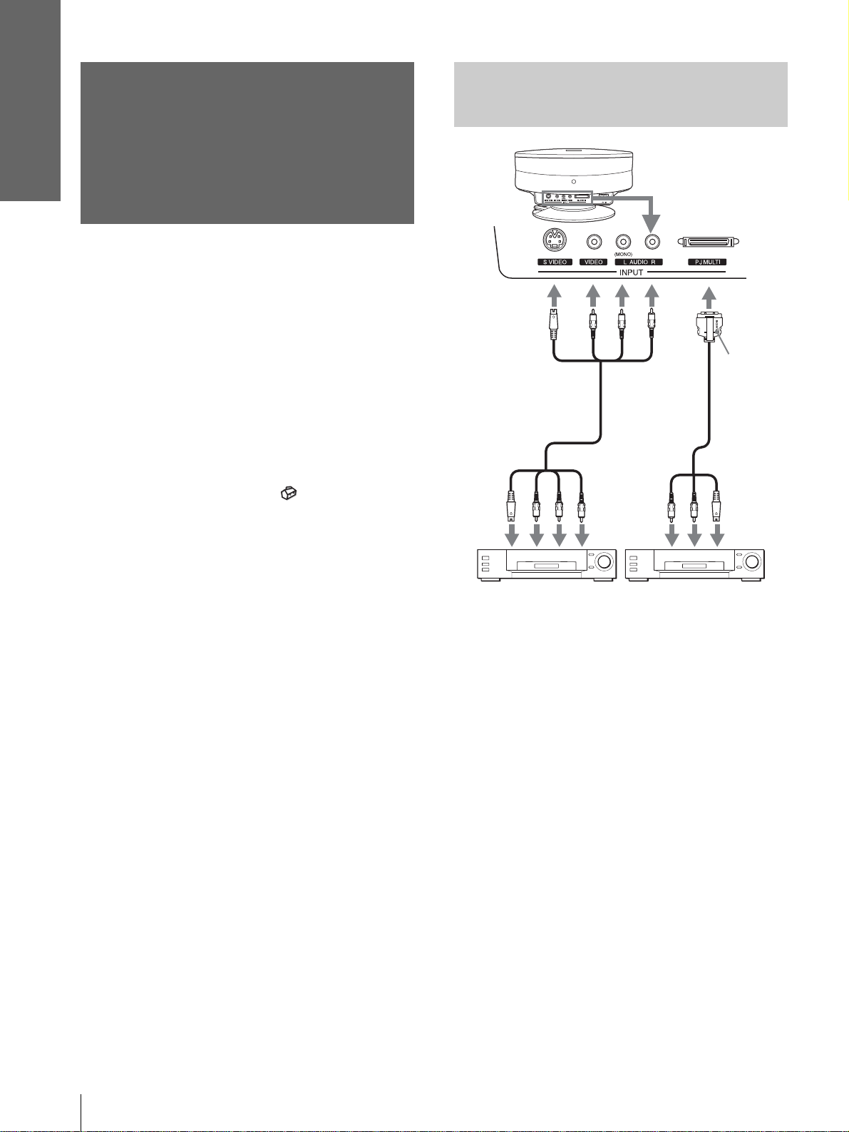
Connecting with Video
Equipment
Connecting the
Projector
When making connections, be sure to do the
following:
• Turn off all equipment before making any
connections.
• Use the proper cables for each connection.
• Insert the cable plugs properly; plugs that are not
fully inserted often generate noise. When pulling
out a cable, be sure to pull it out f rom the plug , not
the cable itself.
• Refer to the operat ing inst ructions of the co nnected
equipment.
• When you connect your projector to PJ MULTI,
select the input signal with the “In put-A Signal Sel. ”
setting in the SET SETTING menu. (1 page
27)
to S
video
or
video/
audio
output
S Video or
video/audio
cable (not
supplied)
Rear of the projecto r
Signal
interface
cable
(supplied)
to S video/
audio
output
with SONY
logo
upside
Video equipment
Video equipment
GB
10
Step 2: Connecting the Projector
Page 11
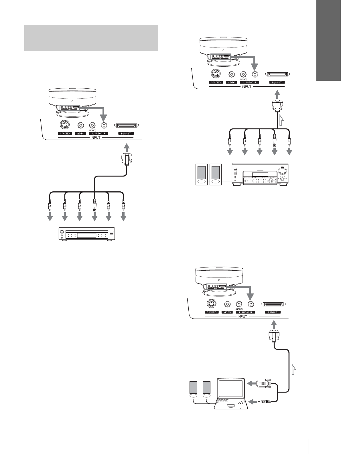
Connecting Using the Optional
Signal Interface Cables
To connect with a DVD player
equipped with the component video
connectors/digital tuner
Rear of the projector
Connections and
Preparations
Connecting an AV amplifier
Rear of the projector
Signal interface cable
(SIC-HS40, not supplied)
to S video or
video output
to component
video output
Signal interface cable
(SIC-HS20, not supplied)
to RGB/
component
output
PR/
B/
P
Y
C
B
DVD play er w ith com pone nt vid eo co nnec tors,
digital tuner, etc.
S
C
R
Video
Audio L
to S video/
audio
output
Audio R
YP
Active speakers
B/
B
C
AV amplifier
PR/
C
S
R
Video
Video
Connecting a Computer
To hear the sound from a computer, use the speakers
built in the comput er or connect the activ e speakers t o
the computer.
Note
Even if you connect the signal interface cable to the audio output
on the computer, there is no sound output from the project or.
Rear of the projector
Active
speakers
Signal interface cable
(SIC-HS30, not supplied)
to monitor
output
Computer
Step 2: Connecting the Projector
11
GB
Page 12
Connections and
Preparations
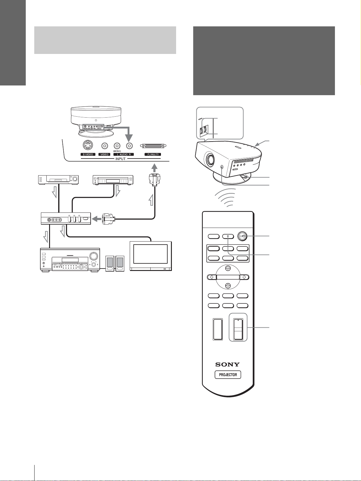
Connecting Using the
Optional Interfa ce Unit
Step 3: Adjusting
Using the optional interface unit allows you to
connect various video equipment, and to select the
output to the projector or TV from the connected
equipment simply by switching the select switch on
the interface unit.
Rear of the
projector
VCR, etc.
to PJ multi
output
DVD player, etc.
Interface unit
(IFU-HS1, not supplied)
PJ multi cable (supplie d
with the IFU-HS1)
the Picture Size
and Position
6
5,7
INPUTLIGHT
Rear remote control
detector
Ajuster lock lever
Front remote control
detector
2
STANDARD
USER 2
CINEMA
USER 3USER 1
4
DYNAMIC
PICTURE MODE
Audio amplifier
Active
speakers
TV
ENTER
DDE
MENUAPA
MUTING
+
–
RESET
6
WIDE MODE
VOLUME SIDE SHOT
+
–
Tip
The ? /
1 (on/standby), INPUT, MENU, and m/M/</,/
ENTER (joystick) buttons on the side panel of the projector have
the same functions as those on the remote control.
GB
12
Step 3: Adjusting the Picture Size and Position
Page 13
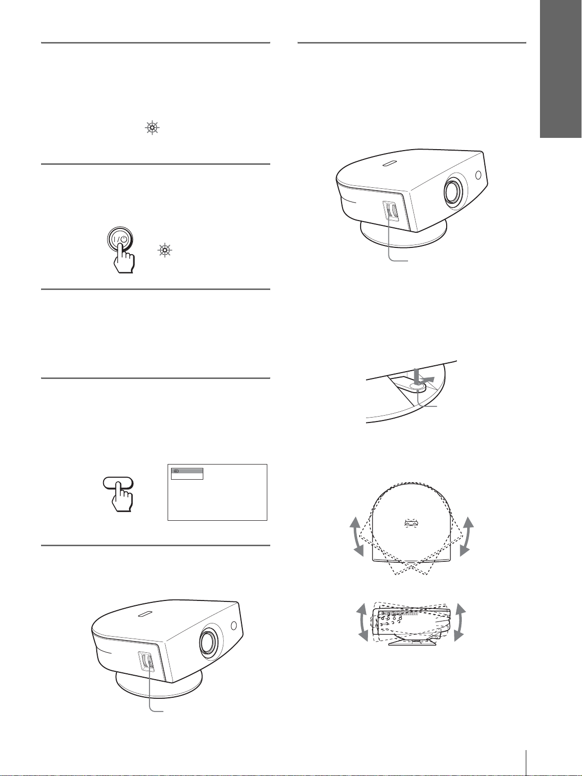
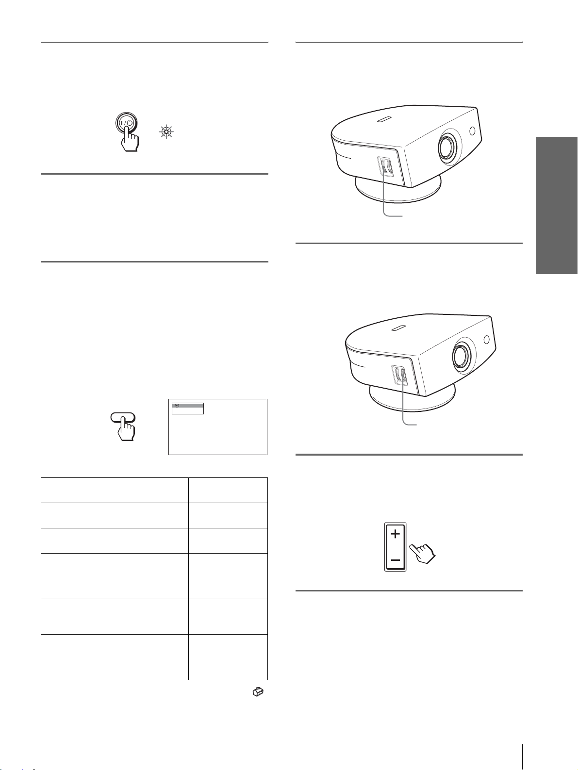
1
Plug the AC power cord into a
wall outlet.
The ON/STANDBY indicator lights in red and
the projector goes into standby mode.
ON/
STANDBY
2
Press the [/1 (on/standby)
Lights in red.
switch to turn on the projector.
The ON/STANDBY indicator lights in green.
6
Adjust the size and position of
the picture to fit the screen
using the ZOOM ring and the
adjuster.
Turn the ZOOM ring to adjust the picture size.
Connections and
Preparations
ON/
Lights in green.
STANDBY
3
Turn on the equipment
connected to the projector.
Refer to the operating instructions of the
connected equipment.
4
Press INPUT to project the
picture on the screen.
Each time you press the button, the input
indication changes. (1 page 19)
Video 1
INPUT
NTSC 3.58
ZOOM ring
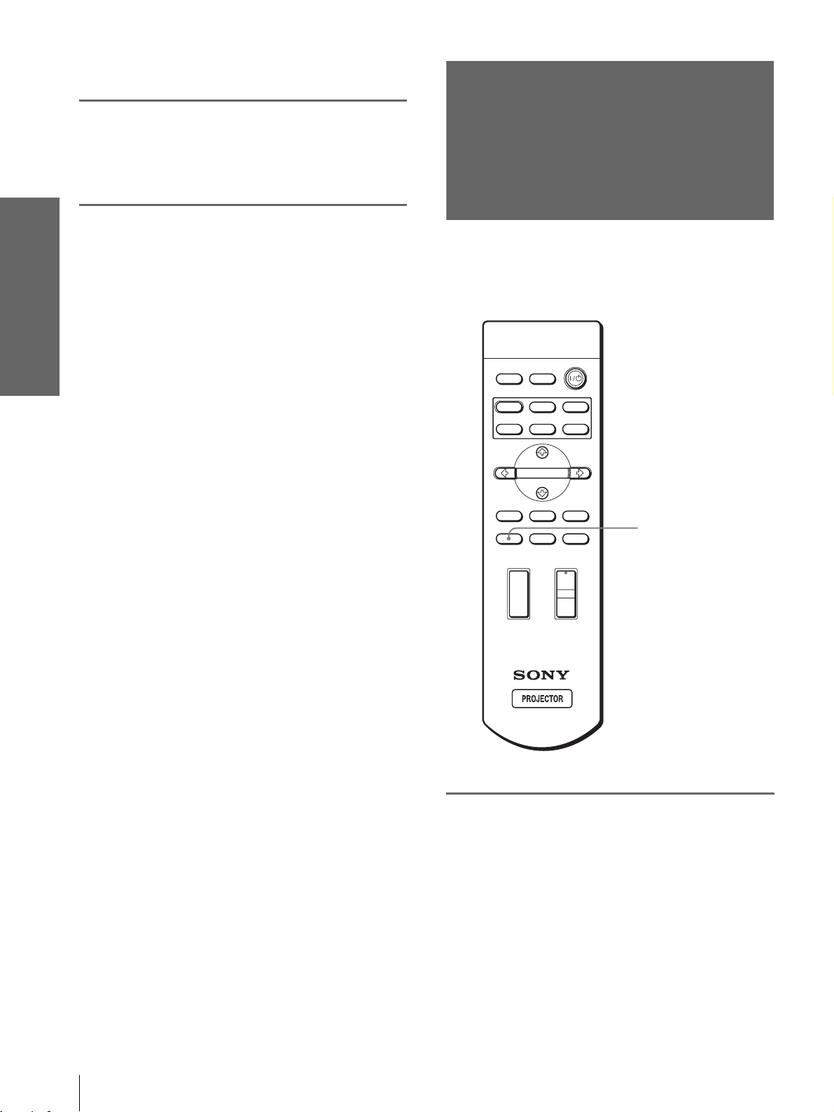
Adjusting the picture position using the
adjuster
Hold down and slide the adjuster lock lever to
the right, move the projector, then return the
lock lever.
Adjuster lock lever
You can move the projector horizontally or
vertically within the following ranges:
5
Adjust the focus r oughly using
the FOCUS ring.
FOCUS ring
Up to 30º each way horizontally
Up to 10º each way
vertically
Step 3: Adjusting the Picture Size and Position
13
GB
Page 14
Connections and
Preparations
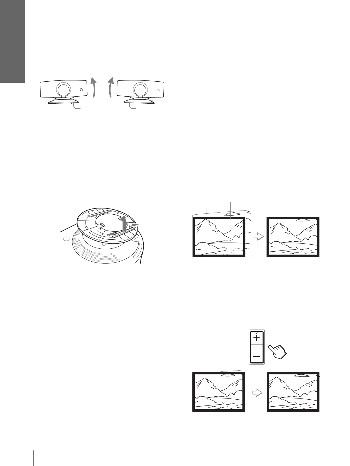
Adjusting the picture position using the
supplied adjuster spacer
Attaching one of the supplied spacers for adjuster
adjustment (spacers for 1
º and 2°) allows you to tilt
the projector to the ri ght or left at a ti lting angl e up to
2
º.
Adjuster
spacer
(supplied)
Adjuster
spacer
(supplied)
To attach the supplied adjuster spacer
1 Place a thick cloth (e.g., a cushion) beneath the
projector. Place the projector face down.
2 While pressing the lock knobs inward, remo ve the
adjuster bar at the bottom of the adjuster table to
which you want to attach the supplied spacer.
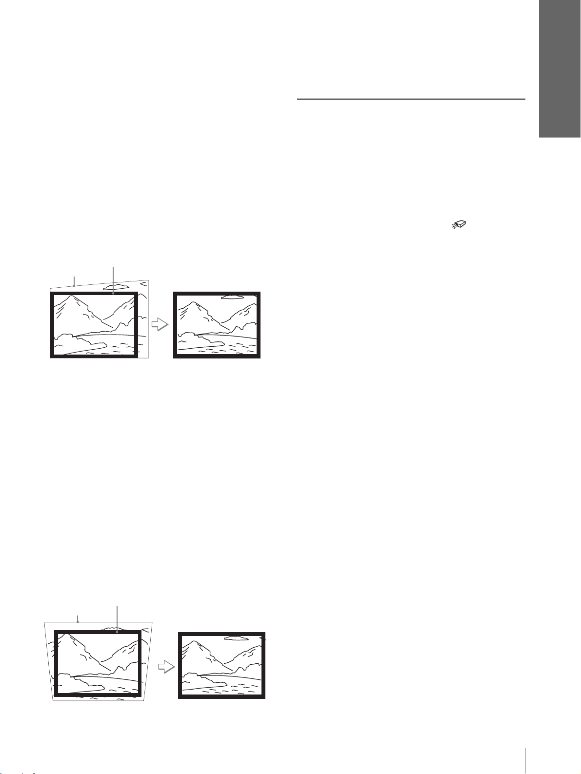
When projecting using both “Side Shot” and
“V Keystone” adjustments
1 Use the adjuster to adjust the vertical
position.
If you set “V Keystone” in the INSTALL
SETTING menu to “Auto” (1 page 27), the
vertical distortion will be automatically corrected .
Note
The “V Keystone” adjustment may not correct trapezoidal
distortion perfe ctly , depending on the room temper ature or the
screen angle. In this case, adjust the distortion manually.
2 Adjust so that the left or right side of the
picture fits that of the screen.
If you position the proj ector on the lef t side of the
screen, adjust so th at the left si de of the pictur e fits
the left side of the screen. With the projector
positioned on the right side, adjust so t hat the right
side fits the right side of the screen.
At the same time, align the bottom side of the
picture with that of the screen.
Screen
Picture
3 Fit the spacer into the removed adjuster bar spot.
3 Adjust to correct horizontal trapezoidal
distortion using the SIDE SHOT + or –
button.
Press SIDE SHO T + or – so that the upper side of
the picture becomes parallel to the bottom side. If
the left side is longer than the right side, press
SIDE SHOT –.
SIDE SHOT
Press SIDE SHOT + if the right side i s longer . To fineadjust the distortion, press M or m.
GB
14
Step 3: Adjusting the Picture Size and Position
Page 15
Connections and
Preparations
When projecting using “Side Shot”
adjustment only
1 Set “V Keystone” in t he INST ALL SETTING
to “Manual,” and set the level to “0” (1
page 27) or press RESET.
2 Adjust so that the left or right side of the
picture fits that of the screen.
If you position the proj ector on the le ft sid e of th e
screen, adjust so t hat the left si de of the pictur e fits
the left side of the screen. With the projector
positioned on the ri ght side, adjust so that the right
side fits the right side of the screen.
At the same time, adjust the vertical size of the
aligned side of the picture to fit the screen using
the ZOOM ring.
Screen
Picture
Note
The V Keystone adjustment may not correct trapezoidal distortion
perfectly, depending on the room temperature or the screen angle.
In this case, adjust the distortion manually.
7
Turn the FOCUS ring to adjust
the focus again.
Tip
When you adjust distortion manually using “V Keystone”
and the SIDE SHOT buttons in steps 6 and 7, the built-in
test pattern is projected on the screen. If you want to make
adjustments using the current input signal, set “Test
Pattern” in the INSTALL SETTING menu to “Off.”
(1 page 27)
3 Adjust to correct horizontal trapezoidal
distortion using the SIDE SHOT + or –
button.
For how to correct, see step 3 in
projecting using both
Keystone
When projecting fr om th e center
Adjust so that both the position and size of
the bottom side of the picture fit those of the
bottom side of the screen using the adjuster
and the ZOOM ring.
If you set “V Keystone” in the INSTALL SETTING
menu to “Auto” (1 page 27), the vertical distortion
will be automatically corrected.
Picture
” adjustments.”
Screen
“Side Shot” and “V
“When
Step 3: Adjusting the Picture Size and Position
15
GB
Page 16
Connections and
Preparations
Step 4:
Selecting the
1
Plug the AC po wer cord into a
wall outlet.
The ON/STANDBY indicator lights in red and
the projector goes into standby mode.
Menu Language
You can select one of nine languages for displaying
the menu and other on-screen displays. The factory
default setting is Englis h.
INPUTLIGHT
STANDARD
DYNAMIC
PICTURE MODE
USER 2
ENTER
DDE
MUTING
WIDE MODE
VOLUME SIDE SHOT
+
+
CINEMA
USER 3USER 1
MENUAPA
RESET
2
4-6
3
ON/
STANDBY
2
Press the [/1 (on/standby)
Lights in red.
switch to turn on the pr ojector.
The ON/STANDBY indicator lights in green.
ON/
Lights in green.
STANDBY
3
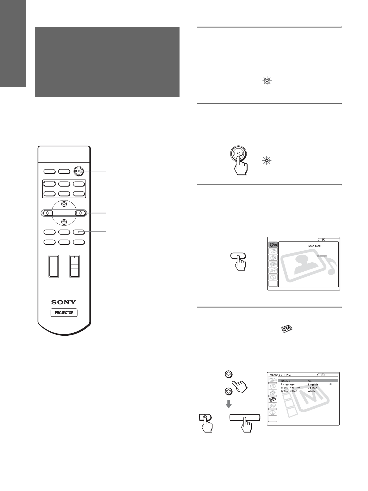
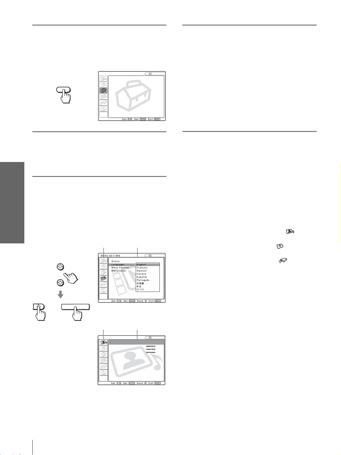
Press MENU.
The menu appears.
The menu presently se lected is shown as a
yellow button.
PICTURE SETTING
Picture Mode:
Adjust Picture...
MENU
Volume: 30
Input A
–
Tip
You can operate the menu using the joystick on the side panel of
the projector instead of the M/m/</,/ENTER buttons on the
remote control.
–
4
Press M or m to select the
MENU SETTING menu, and
press , or ENTER .
The select ed menu appears.
:
:
:
:
or
ENTER
Input A
A
GB
16
Step 4: Selecting the Menu Language
Page 17
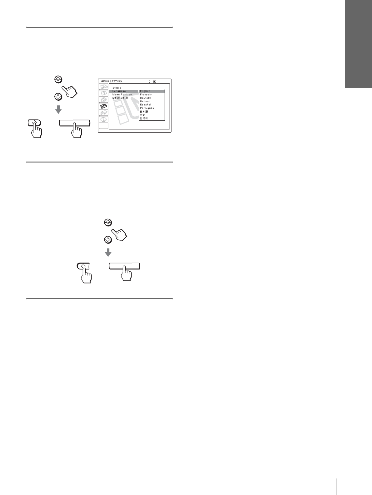
5
Press M or m to select
“Language”, and press , or
ENTER.
Connections and
Preparations
:
:
or
6
Press M or m to select a
ENTER
language, and press < or
ENTER.
The menu changes to the selected language.
Input A
:
:
To clear the menu
Press MENU.
or
ENTER
Step 4: Selecting the Menu Language
17
GB
Page 18
Projecting
Projecting the
This section describes how to operate the
projector to view the picture from the
equipment connected to the projector. It
also describes how to select the wide
screen mode or the quality of the picture to
suit your taste.
Picture on the
Screen
4
INPUTLIGHT
2
STANDARD
USER 2
ENTER
DDE
MUTING
+
CINEMA
USER 3USER 1
MENUAPA
RESET
MUTING button
DYNAMIC
PICTURE MODE
WIDE MODE
VOLUME SIDE SHOT
+
–
–
7
1
Plug the AC po wer cord into a
wall outlet.
The ON/STANDBY indicator lights in red and
the projector goes into standby mode.
ON/
Lights in red.
STANDBY
GB
18
Projecting the Picture on the Screen
Page 19
2
Press the [/1 (on/standby)
switch to turn on the projector.
The ON/STANDBY indicator lights in green.
ON/
STANDBY
3
Turn on the equipment
Lights in green.
connected to the projector.
Refer to the operating instructions of the
connected equipment.
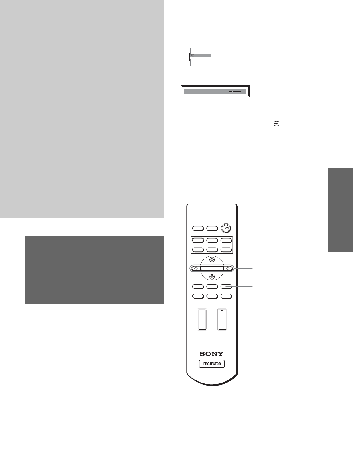
4
Press INPUT repeatedly to
select the input you want to
project on the screen.
Display the indication of the input you want.
5
Turn the ZOOM ring to adjust
the size of the picture.
ZOOM ring
6
Turn the FOCUS ring to adjust
the focus.
Adjust to obtain sharp focus.
Projecting
Example:To view the picture from the video
equipment connected to the VIDEO
INPUT jack.
Video 1
INPUT
To view the picture from
Video equipment connected to
VIDEO INPUT on the projector
Video equipment connected to S
VIDEO INPUT on the projector
RGB/component equipment
connected to PJ MULTI INPUT via
the optional signal interface cable or
the interface unit
Video equipment connected to PJ
MUL TI INPUT via the optional signal
interface cable or the interface unit
Video equipment equipped with S
VIDEO connected to PJ MULT I
INPUT via the optional signal
interface cable or the interface unit
*
Set the “Input-A Signal Se l.” setting in the SET SETTING
menu according to the input signal . (1 page 27)
NTSC 3.58
Press INPUT to
display
Video 1
S-Video 1
*
Input-A
Video 2
S-Video 2
FOCUS ring
7
Press V OLUME + or – to adjust
the volume.
VOLUME
Projecting the Picture on the Screen
19
GB
Page 20
Cutting off the sound
Press MUTING on the remote
control.
To restore the sound, press MUTING again.
Selecting the Wide
Screen Mode
Projecting
To turn off the power
1 Press the [/1 (on/standby) switch.
A message “POWER OFF?” appears on the
screen.
2 Press the [/1 switch again.
The ON/ST ANDBY indicator flashes in green and
the fan contin ues to run to r educe the int ernal heat.
Also, the ON/ST ANDBY indicator flashes quickly
during which you will not be able to light up the
ON/STANDBY indicator with the [/1 switch.
3 Unplug the AC power cord from the wall
outlet after the fan stops running and the
ON/STANDBY indicator lights in red.
You can turn off the project or b y holdi ng the [/1 (on/
standby) switch for about one second, instead of
performing the above steps.
Y ou can en joy variou s wide screen mode according to
the video signal re ceived. You can also select it using
the menu. (1 page 26)
INPUTLIGHT
STANDARD
USER 2
ENTER
DDE
MUTING
CINEMA
USER 3USER 1
RESET
+
–
MENUAPA
WIDE MODE button
DYNAMIC
PICTURE MODE
WIDE MODE
VOLUME SIDE SHOT
+
–
GB
20
Press WIDE MODE.
Each time you press the button, you can select
the “Wide Mode” setting.
Selecting the Wide Screen Mode
Page 21
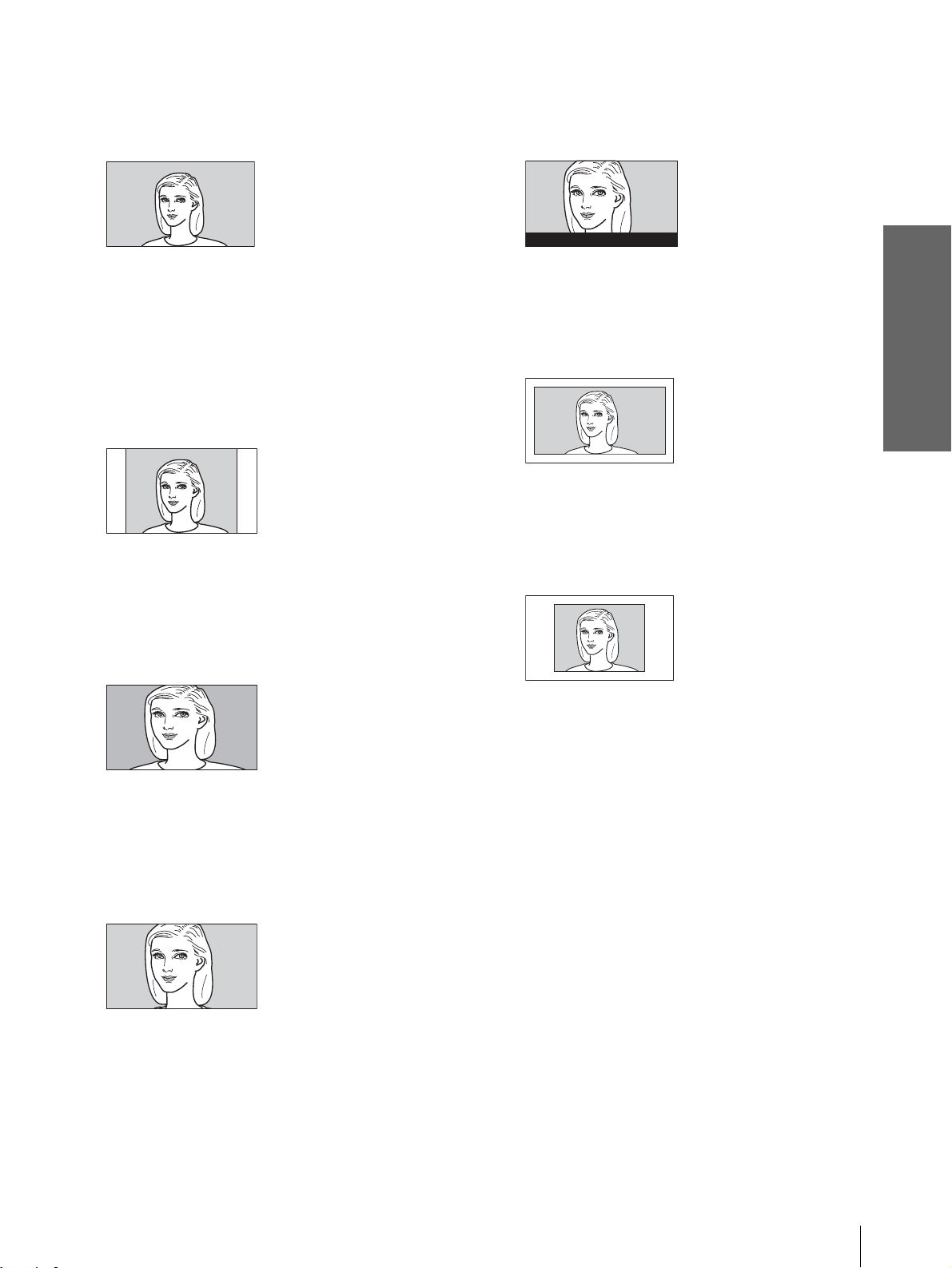
Full
A 16:9 squeezed picture is displayed with the
correct aspect ratio. A 4:3 picture is enlarged
horizontally to fit the 16:9 screen.
Subtitle
The subtitle area is compressed and displayed in
the lower part of the screen. Use this mode to
view a movie with subtitles.
Good-bye
Tip
Squeezed: An original 16:9 aspect ratio picture is recorded
horizontally compressed to a 4: 3 picture.
Normal
A picture with normal 4:3 aspect ratio is
displayed in the center of the screen to fil l the
vertical screen size.
Wide Zoom
A 4:3 aspect ratio picture is enlarged and the
upper and lower portions of the picture are
compressed to fit the 16:9 screen. Use this mode
to view news, variety shows, etc.
Zoom
A normal 4:3 aspect ratio picture is enlarged
vertically and horizontal ly in the same ra tio to
fill the 16:9 screen. This mode is ideal for
viewing a wide-format movie.
Full Through
One-to-one mapping is done on a squeeze d 16:9
picture. It is displayed in the center of the
screen.
Normal Through
One-to-one mapping is done on a 4:3 normal
aspect ratio picture. It is displayed i n th e center
of the screen.
Notes
• You can adjust the vertical position of the picture with
“V Position” in the INPUT SETTING menu when
“Zoom” or “Subtitle” is selected, or when “Full
Through” or “Normal Through” is selected for video
(50Hz) or progressive component (50p) input signal.
• You can adjust the position of the subtitles with “Title
Area” in the INPUT SETTING menu only when
“Subtitle” is selected.
• If “Full Through” or “Normal Through” is selected when
a video (50 Hz) or progressive vide o (50p) signal is
input, the picture may not be comple te ly disp la yed on
the screen due to the number of dots of the LCD panel.
Projecting
Notes on selecting the wide screen mode
• Select the wide screen mode taking into account
that changing the aspect rati o of the ori ginal picture
will provide a different look from that of the
original image.
• Note that if the projector is used for profit or for
public viewing, modifying the original picture by
switching to the wide mode may constitute an
infringement of the rights of authors or producers,
which are legally protected.
Selecting the Wide Screen Mode
21
GB
Page 22

Selecting the
Picture Viewing
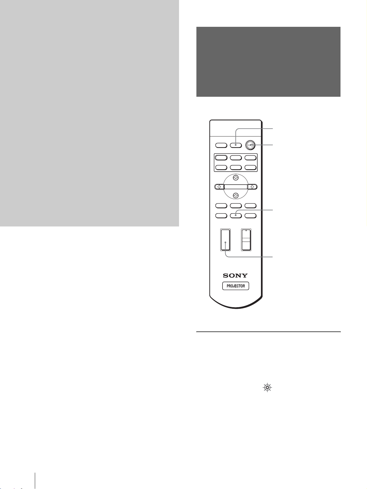
Press one of the PICTURE
MODE buttons (DYNAMIC,
STANDARD, CINEMA and
USER 1, 2 and 3).
Projecting
Mode
You can select the picture viewing mode that best
suits the type of program or room condition.
INPUTLIGHT
STANDARD
USER 2
ENTER
DDE
MUTING
+
–
CINEMA
USER 3USER 1
MENUAPA
RESET
PICTURE MODE buttons
DYNAMIC
STANDARD
CINEMA
USER 1, 2 and 3
DYNAMIC
PICTURE MODE
WIDE MODE
VOLUME SIDE SHOT
+
–
DYNAMIC
Select for enhanced picture contrast and
sharpness.
STANDARD
Recommended for normal vie wi ng con dit ion in
your home.
Also select to reduce roughness when viewing
the picture with DYNAMIC.
CINEMA
Select for soft, film-like pictu re.
USER 1, 2 and 3
You can adjust the quality of the picture to suit
your taste and store t he settings in to the selected
memory of the projecto r . Press one of the USER
1, 2 and 3 buttons, then adjust the picture by
using the menus. The settings are stored, and
you can view the picture with the adjusted
picture quality by pre ssing t he b utto n. (1 page
25)
GB
22
Selecting the Picture Viewing Mode
Page 23
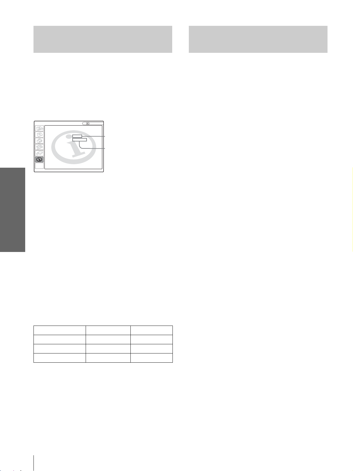
Display items
Using the
Menus
This section describes how to make
various adjustments and settings using the
menus.
Input signal indicator
Video 1
NTSC 3.58
Input signal setting indicator
Picture adjustment menu
Contrast: Min
Input signal indicator
Shows the selected input channel. is displayed
when no signal is input. You can hide this indicator
using “Status” in the MENU SETTING menu.
Input signal setting indicator
For Input-A: Shows “Computer,” “Component” or
“Video GBR.”
For V ideo/S V ideo input: Sho ws “ Auto” or the “Color
System” setting in the SET SETTING menu.
x
Using the Menus
Operation through
the Menus
The projector is equipped wi th an on-screen me nu for
making various adj ustment s and set ting s. The set ting
items are displayed in a pop-up menu or in a sub
menu. If you select an item name followed by dots
(...), a sub menu with setting items appear. You can
change the tone of the menu display and the menu
language displayed in the on-screen menu.
To change the menu language, see “Selecting the
Menu Language” on page 16.
INPUTLIGHT
STANDARD
DYNAMIC
PICTURE MODE
USER 2
ENTER
DDE
MUTING
WIDE MODE
VOLUME SIDE SHOT
+
–
+
–
CINEMA
USER 3USER 1
MENUAPA
RESET
2-4
1
Operation through the Menus
23
GB
Page 24
1
Press MENU.
The menu appears.
The menu presently selected is shown as a
yellow button.
SET SETTING
Smart APA: On
Auto Input Search:
Input-A Signal Sel.:
MENU
Color System: Auto
Power Saving: Off
Illumination: Off
Off
Computer
Input A
4
Make the setting or adjustment
on an item.
When changing the adjustment level
To increase the value, press M or ,.
T o decrease the value, press m or <.
Press ENTER to restore the original screen.
When changing the setting
Press M or m to change the setting.
Press < or ENTER to restore the original
screen.
2
Press M or m to select a men u,
and press , or ENTER.
To clear the menu
Press MENU.
The select ed menu appea rs.
Using the Menus
To reset items that have been
adjusted
3
Press M or m to select an item
you want to adjust and press
, or ENTER .
The setting items are displayed in a pop-up
menu or in a sub menu.
Pop-up menu
Menu Setting items
or
ENTER
Input A
Select the item you want to reset, then press RESET.
“Complete!” appears on the screen and the setting is
reset to its factory preset value.
Items that can be reset are:
• “Contrast,” “Brightness,” “Color,” “Hue,”
“Sharpness” and “RGB Enhancer” in “Adjust
Picture...” of the PICTURE SETTING menu
• “Dot Phase,” “H Size” and “Shift” in “Adjust
Signal...” of the INPUT SETTING menu
• “V Keystone” (when set to “Manual”) and “Side
Shot” of the INASTALL SETTING menu
GB
24
Operation through the Menus
Sub menu
Menu Setting items
Graphics
High
Input A
PICTURE SETTING
ADJUST PICTURE
Contrast: 80
Brightness: 50
RGB Enhancer: 30
Gamma Mode:
Color Temp:
Standard
Page 25
Menu Lists
Menu Configurations
The projector is equipped with six pages. The items
that can be adjusted in each menu are described on
page 25 to 27.
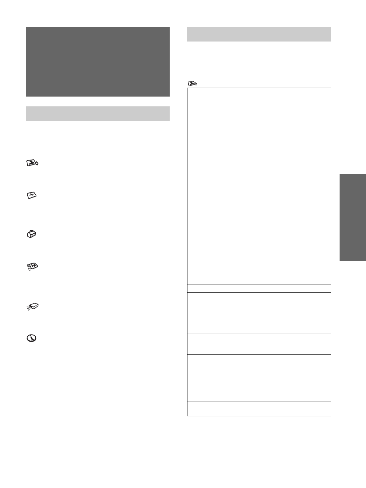
PICTURE SETTING menu
The PICTURE SETTING menu is used for adjusti ng
the picture. You can also adjust the volume.
INPUT SETTING menu
The INPUT SETTING menu is used to adjust the
input signal. You can adjust the size of the picture, and
select wide screen mode, etc.
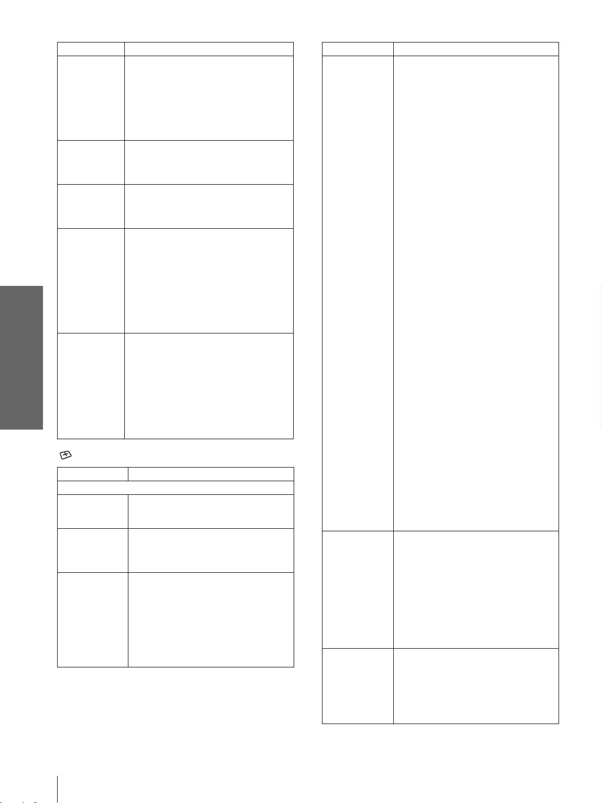
SET SETTING menu
The SET SETTING menu is used for changing the
settings of the projector.
MENU SETTING menu
The MENU SETTING menu is used to change the onscreen language, disp lay position of the menu screen,
etc.
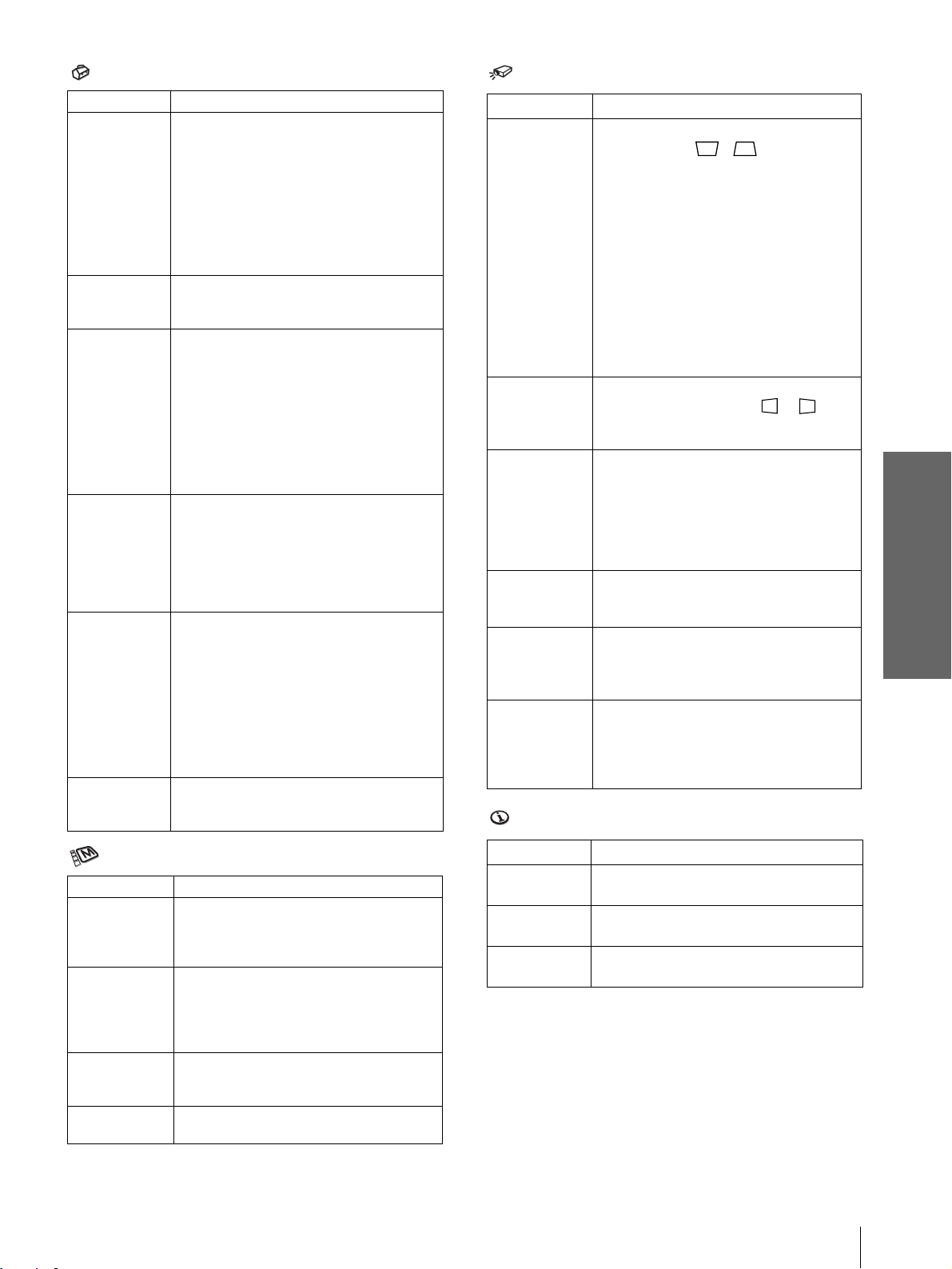
INSTALL SETTING menu
The INST ALL SETTI NG menu is used for cor recting
distortion of the picture.
INFORMATION menu
The INFORMATION menu is used to display the
horizontal and ve rtical freq uencies of the in put signal
and the used time of the lamp.
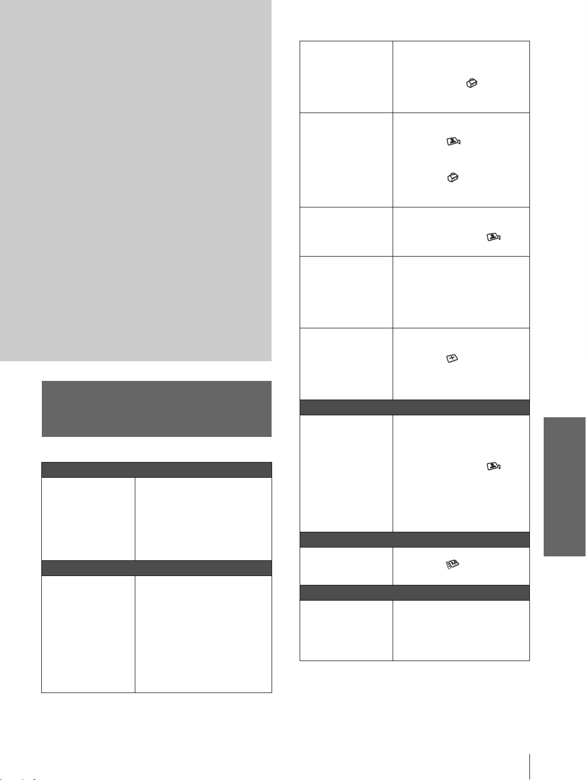
Menu Items
Adjustable items are limited according to the input
signals. Items that cannot be adjusted are not
displayed in the menu. (1 page 38)
PICTURE SETTING
Item Description
Picture Mode You can select picture viewing mode that
Volume Adjusts the volume.
Adjust Picture…
Contrast The higher the setting, the greater the
Brightness The higher the setting, the brighter the
Color The higher the setting, the greater the
Hue The higher the setting, the more greenish
Sharpness The higher the setting, the sharper the
RGB
Enhancer
best suits the type of picture or the
environment.
Dynamic: Select for enhanced picture
contrast and sharpness.
Standard: Recommended for normal
viewing condition. Also select to reduce
roughness when viewing the picture
with Dynamic.
Cinema: Select for soft, film-like picture.
User 1, 2 and 3: You can adjust the
quality of the picture to suit your taste
and store the settings. Once the settings
are stored, you can view the picture with
the adjusted picture quality by pressing
the PICTURE MODE button.
To store the settings
1 Select “User 1”, “User 2” or “User
3”.
2 Adjust the items you want in the
menus.
Items that can be stored are:
“Adjust Picture...” items other than
“Volume,” and “Wide Mode” setting
Tip
You can also adjust the picture quality
in “Dynamic”, “Standard” or “Cinema”
mode. To reset to the factory setting,
press RESET.
contrast. The lower the setting, the lower
the cotrast.
picture. The lower the setting, the darker
the picture.
intensity. The lower the setting, the lower
the intensity.
the picture becomes. The lower the
setting, the more purplish the picture
becomes.
picture. The lower the setting, the softer
the picture.
Adjusts the picture sharpness when
computer signals are input.
Using the Menus
Menu Lists
25
GB
Page 26
Item Description
Black Level
Adj (Adjust)
Emphasizes black color to produce a
bolder “dynamic” picture. Set according
to the input signal source.
High: Gives higher emphasis to the black
color.
Low: Gives lower emphasis to the black
color.
Off: Cancels this feature.
Gamma Mode Graphics: Reproduce s t he photos in
natural tones.
Text: Contrasts black and white. Suitable
for images that contain lots of text.
Color Temp. High: Gives the white colors a blue tint.
Middle: Gives the white colors a neutral
tint.
Low: Gives the white colors a red tint.
DDE
(Dynamic
Detail
Enhancer)
Off: Plays a video signal in an interlace
format without converting.
Progressive: Converts an interlace format
video signal to a progressive format .
Film: Normally, select this option.
Reproduces the 2-3 Pull-Down film
Using the Menus
sources with smoo th pic tu re mo v eme nt.
When the video signal with a format
other than the 2-3 Pull-Down is input,
“Progressive” is automatically selected.
Cinema Black Switches the lamp wattage during
projection.
On: Enhances the black by reducing the
lamp wattage.
Off: Normal wattage.
Tip
If “Cinema Bla ck” is set to “On,” the next time
the power is turned on, the lamp will use the
“Off” setting for the first time, and then go to
“On.”
INPUT SETTING
Item Description
Adjust Signal…
Item Description
Wide Mode You can select the 4:3 aspect ratio picture
mode, “Normal” and “Normal Through,”
and 16:9 aspect ratio picture mode,
“Full,” “W ide Zoom, ” “Zoom, ” “Subtitle”
and “Full Through.”
Full: The 16:9 squeezed* picture is
diplayed with the correct aspect. The
4:3 picture is e nlarged horizontally to
fit the 16:9 screen.
* squeezed: An original 16:9 aspect
ratio picture is recorded horizontally
compressed to be a 4:3 picture.
Normal: The picture with normal 4:3
aspect ratio is displayed to fill the
vertical screen size.
Wide Zoom: The picture with 4:3 aspect
ratio is enlarged and the upper and
lower portions of the picture are
compressed to fit the 16:9 screen. Use
this mode to view news, variety shows,
etc.
Zoom: The normal 4:3 aspect ratio
picture is enlarged verticall and
horizontally at the equal ratio to fill the
16:9 screen. The mode is ideal for
viewing a wide-format movie.
Subtitle: The subtitle area is compressed
and displayed at the lower part of the
screen. Use this mode to view a movie
with the subtitle.
Full Through: One-to-one mapping is
done on a squeezed 16:9 picture. It is
displayed in the center of the screen.
Normal Through: One-to-one mapping
is done on the picture with 4:3 aspect
ratio. It is displayed in the center of the
screen.
Note
If “Full Through” or “ N ormal Through” is
selected when a video (50 Hz) or progressive
video (50p) signal is input, the picture may not
be completely displayed on the screen due to the
number of dots of the LCD panel.
Dot Phase Adjusts the picture from a computer for
clearer picture after it is adjusted by
pressing the APA button.
H Size Adjusts the horizontal size of the picture
from a computer. The higher the setting,
the wider the picture. The lower the
setting, the narrower the picture.
Shift As the setting for H (horizontal)
increases, the picture moves to the right,
and as the setting decreases, the picture
moves to the left. Use < or , to adju st
the horizontal position.
As the setting for
V (vertical) increases,
the picture moves up, and as the setting
decreases, the picture moves down. Use
M or m to adjust the vertical position.
V Position Adjusts the vertical position of the picture
Title Area Adjusts the subtitle area. As the setting
For details, see “Selecting the Wide
Screen Mode” on page 20.
in wide screen mode. As the setting
increases, the picture moves up. As the
setting decreases, the picture moves
down.
Note
This item is adjustable only when “Zoom” or
“Subtitle” is selected, or when “Full Through”
or “Normal Thro ugh” is selected for video
(50Hz) or progressive component (50p) input
signal.
increases, the subtitle area moves up. As
the setting decreases, the subtitle area
moves down.
Note
This item is adjustable only when “Subtitle” is
selected.
GB
26
Menu Lists
Page 27
SET SETTING
Item Description
Smart APA With this item set to On, the APA function
Auto Input
Search
Input-A Signal
Sel.
Color System Select the color system of the input signal.
Power Saving When set to On, the POWER SAVING
Illumination Turns on the illumination on the top panel
works automatically for a signal input from
a computer so that the picture can be seen
clearly. You can also activate the APA
function by pressing the AP A bu tton on the
remote control.
Tip
The APA (Auto Pixel Alignment) automatically
adjusts the input signal from a computer so that
the picture can be seen clearly.
Set to On when an optional Interface Unit
such as the IFU-HS1 is connected to the PJ
MULTI connector on the projector.
Selects the signal input from the equipment
by selecting “Input-A” with the INPUT
button.
Computer: Inputs the signal from a
computer.
Component: Inputs the component or
progressive component signal from a
DVD player, digital tuner, etc.
Video GB R: Inputs the signal fro m a
digital tuner.
Auto: Selects the color system of the input
signal automatically from among NTSC,
PAL, SECAM, NTSC
PAL-N.
“NTSC3. 58”–“PAL-N”: Sets the color
system to the selected system manually.
indicator lights. The projector goes into
power saving mode if no signal is input for
10 minutes, and the lamp goes out and the
cooling fan keeps running. In power saving
mode, no button functions for the first 60
seconds. It is cancelled when a signal is
input or any b utt on is pres sed. If you do not
set the projector to power saving mode,
select Off.
of the projector when set to On. It turns off
when set to Off.
4.43, PAL-M or
INSTALL SETTING
Item Description
V Keystone Corrects the vertical trapezoidal distortion
Side Shot Corrects the horizo ntal trapezoidal
Image Flip Flips the picture on the screen horizontally
Background Selects the background color of the screen
Test Pattern When set to On, a test pattern is displayed
High Altitude
Mode
of the picture. ( )
Auto: Normally set to this postion.
Manual: Sets a lower value (– direction)
when the bottom of the trapezoid is
longer than the top. Sets a higher value
(+ direction) when the top of the
trapezoid is longer than the bottom. If
you project the picture using “Side
Shot” only, set to “Manual,” and adjust
the level to “0.”
Note
The “V Keystone” adjustment may not correct
the trapezoidal distortion perfectly, depending on
the room temperature or the screen angle. In this
case, adjust the di stortion manually.
distortion of the picture. ( )
Set the level to “0” when you adjust the
picture using “V Keystone” only.
and/or vertically.
Off: The picture does not flip.
HV: Flips the picture horizontally and
vertically.
H: Flips the picture horizontally.
V: Flips the picture vertically.
when no signal is input. You can select
“Black” or “Blue.”
on the screen when adjusting using “Side
Shot” or “V Keystone. ” I f yo u do not want
to display a test pattern, set to Off.
Off: Use this setting when using the
projector at normal altitudes.
On: Use this setting when using the
projector at an altitude of 1,500 m or
higher.
INFORMATION
Using the Menus
MENU SETTING
Item Description
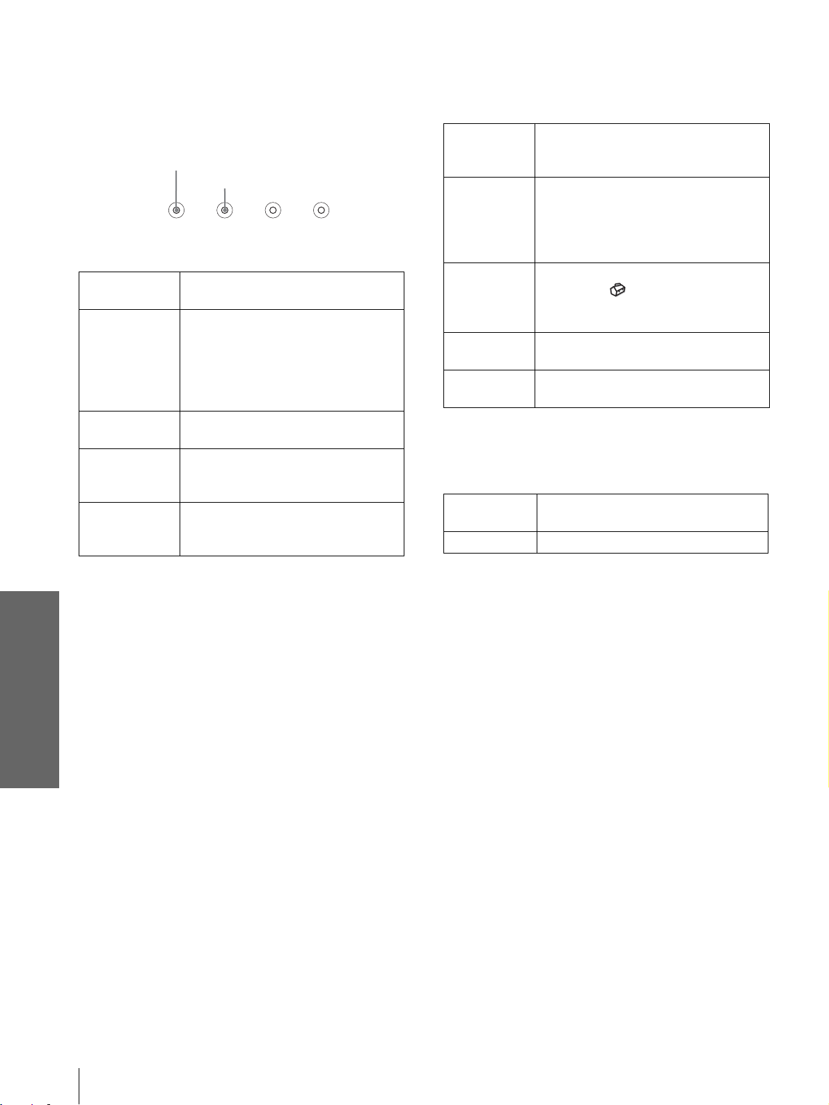
Status Set to Off to turn off the on-screen
displays except for the menus, message
when turning off the power, and warning
messages.
Language Selects the la ng ua g e used in the menu an d
on-screen dis plays. Available languages
are: English, French, German, Italian,
Spanish, Portuguese, Japanese, Chinese
and Korean.
Menu Position Selects the display position from Top
Left, Bottom Left, Center, To p Right
and Bottom Right.
Menu Color Selects the tone of the menu display from
White or Black.
Item Description
fH Displays the horizontal frequency of the
input signal.
fV Displays the vertical frequency of the input
signal.
Lamp Timer Indicates how long the lamp has been
turned on.
Menu Lists
27
GB
Page 28
About the Preset Memory
Adjusting Picture Quality of
No.
This projector has 35 types of preset data for input
signals (the preset memory ). When the preset signal is
a Signal from the Computer
You can automatically adjust to obtain the clearest
picture when projecting a signal from the computer.
input, the projector automatically detects the signal
type and recalls th e data for the s ignal fr om the preset
memory to adjust it to an optimum picture. The
memory number and signal type of that signal are
displayed in the INFORMATION menu.
INFORMATION
fH: 48.47kHz
fV: 60.00Hz
No.23
1024x768
Lamp Timer: 0H
Input A
Memory No.
Signal type
Using the Menus
Y ou can als o adjust the preset da ta through the INPUT
SETTING menu.
This projector also has 20 types of user memori es for
Input-A into which you can save the setting of the
adjusted data for an unpreset input signal.
When an unpreset signal is input for the first time, a
memory number is displayed as 0. When you adjust
1 Project a still picture from the com puter.
2 Press the APA (Auto Pixel Alignment)
button.
When the picture is adjuste d properly, “complete”
appears on the screen.
Notes
• When “Smart APA” is set to “On,” the APA function is
automatically activated.
• Press the APA button when the image appears on the whole
display area of the computer. If there are black edges around the
image, the APA function will not function properly and the
image may extend beyond the screen.
• If you switch the input signal or re-connect a computer, press
the APA button again to get the suitable picture.
• To restore the original screen, press the APA button again
during the adjustment.
• The picture may no t be adjusted properly depending on the
types of input signals.
• Adjust the items in the INPUT SETTING menu when you
adjust the picture manually. (1 page 26)
the data of the s ig nal in th e I N PUT SETTI NG menu ,
it will be registered to the projector. If more than 20
user memories are registered, the newest mem ory
always overwrites the oldest one.
See the chart on page 39 to find if the signal is
registered to the preset memory.
GB
Since the data is recalled from the preset memory
about the following signals, you can use these preset
data by adjusting “H size.” Make fine adjustment by
adjusting “Shift.”
Signal Memory No. H size
Super Mac-2 23 1312
SGI-1 23 1320
Macintosh 19” 25 1328
Note
When the aspect ratio of input signal does not match the screen
size, a part of the screen is displayed in black.
28
Menu Lists
Page 29
Others
This section describes how to solve the
problems, how to replace a lamp and air
filter, etc.
Troubleshooting
Power
The power is not
turned on.
Picture
No picture. c Check that the proper
c Wait for about one minute
before turning on the power.
(1 page 20)
c Close the lamp cover securely.
(1 page 31)
c Close the air filter cover
securely. (1 page 32)
connections have been made.
(1 page 10)
c Select the input source correctly
using the INPUT button.
(1 page 19)
c Set the computer signal to output
from an external monitor.
c Set the computer signal to output
only to an external monitor.
The picture from the PJ
MULT I connector is
colored strange.
Color balance is
incorrect.
The picture is too dark. c Adjust the c ontr ast or brigh tness
The picture is not clear. c Adjust the focus with the
The picture flickers. c Adjust “Dot Phase” for “Adjust
Sound
No sound. c Check that connecting cables are
On-screen display
On-screen display does
not appear.
Remote control
The remote control
does not work.
c Select “Computer”,
“Component” or “Video GBR”
for “Input-A Signal Sel” in the
SET SETTING menu
according to the input signal.
(1 page 27)
c Adjust the picture in the “Adjust
Picture ...” of the PICTURE
SETTING menu
(1 page 25).
c Set “Color System” in the SET
SETTING menu to match
the color system being input.
(1 page 27)
in the “A djust Picture ...” of the
PICTURE SETTING menu
properly. (1 page 25)
FOCUS ring. (1 page 19)
c Condensation has occurred on
the lens. Leave the projector for
about two hours with the power
on.
Signal...” in the INPUT
SETTING menu properly.
(1 page 26)
c Press MUTING on the remote
control.
properly con nected. (1 page
10)
c Adjust “Volume” in the
PICTURE SETTING menu
(1 page 25), or press
VOLUME + on the remote
control.
c Press MUTING on the remote
control.
c Set “Status” in the MENU
SETTING menu to “On.”
(1 page 27)
c Batteries could be weak.
Replace with new batteries. (1
page 5)
c Insert the batteries with correct
polarities. (1 page 5)
Others
Troubleshooting
29
GB
Page 30
Indicators
The LAMP/COVER or TEMP/FAN indicator on the
control panel lig hts up or flashes if th ere is any trouble
with your projector.
LAMP/COVER Indicator
TEMP/FAN Indicator
LAMP/COVER
flashes.
LAMP/COVER
lights up.
TEMP/FAN
flashes.
TEMP/FAN
lights up.
LAMP/COVER
and TEMP/FAN
light up.
LAMP/
COVER
TEMP/
FAN
POWER
SAVING
ON/
STANDBY
c Attach the lamp cover or the air filter
cover securely. (1 pages 31 and 32)
c The lamp has reached the end of its
life. Replace the lamp. (1 page 31)
c The lamp becomes a high temperature.
Wait for one minute to cool down the
lamp and turn on the power again. (1
page 20)
c The fan is broken. Consult with
qualified Sony personnel.
c The internal temperature is unusually
high. Check to see if nothing is
blocking the ventilation holes.
c The electrical system breaks down.
Consult with qualified Sony
personnel.
Warning Messages
Use the list below to check the meaning of the
messages displayed on the screen.
High temp.!
Lamp off in 1
min.
Frequency is
out of range!
Please check
Input-A Signal
Sel.
Please replace
the LAMP.
Please replace
the filter.
c Turn off the power.
c Check to see if nothing is blocking the
ventilation holes.
c Input a signal that is within the
acceptable range of the frequency.
c Set the output signal on an external
monitor of the connected computer to
SVGA.
c Set “Input-A Signal Sel.” in the SET
SETTING menu to “Computer”
when RGB signal is input from the
computer. (1 page 27)
c It is time to replace the lamp. Replace
the lamp. (1 page 31)
c It is time to replace the air filter. Replace
the air filter. (1 page 32)
Caution Messages
Use the list below to check the meaning of the
messages displayed on the screen.
NO INPUT c No signal is input. Check connections.
(1 page 10)
Not applicable! c Press the appropriate button.
Others
GB
30
Troubleshooting
Page 31

Replacing the Lamp
The lamp used for the light source has a certain life.
When the lamp dims, the color bal ance of the pic ture
becomes st range, or “P lease replace the LAMP.”
appears on the scre en, the lamp is e xhausted . Replace
the lamp with a new one (not supplied).
Use LMP-H150 Projector Lamp as the replacement lamp.
When replacing the lamp after using the
projector
Turn off the projector, then unplug the power cord.
Wait for at least an hour for the lamp to cool
completely.
Caution
The lamp becomes a high temperature after t urning off the
projector with th e [/1 (on/standby) switch. If you touch the lamp,
you may scald your finger. When removing the lamp unit, make
sure it remains horizontal, then pull straight up. Do not tilt the
lamp unit. If you pull out the lamp unit whi le tilted and if the lamp
is broken, the pieces may scatter, causing injury.
2 Open the lamp cover by loosening the
screw with a Philips screwdriver.
3 Loosen the screw on the lamp unit with a
Philips screwdriver. Holding the handle,
pull the lamp unit straight up.
1 Hold down the adjuster lock lever, slide it
to the right, raise the rear o f the projector,
then return the adjuster lock lever. While
keeping the screw on the bottom of the
projector turned inward with a coin or a
slotted screwdriver, open the projector
cover with your hand.
Note
Be sure that the projector is stable.
4 Insert the new lamp all the way in until it is
securely in place. Tighten the screw, and
fold down the handle.
Others
5 Close the lamp cover and tighten the
screw.
Replacing the Lamp
31
GB
Page 32

6 While pushing the projector cover toward
you by holding both sides of the cover on
the lens side, close the cover until it clicks.
Replacing the Air Filter
2
The air filter should be replaced periodically. When
“Please replace the filter.” appears on the screen,
replace th e air filter immediately.
Notes
1
7 Connect the power cord and set the
projector to standby mode .
8 Press the following b uttons on the remote
control in the fol lowing or der for less than
five seconds each: RESET , <, ,, ENTER.
Notes
• Do not put your hands into the lamp replacement spot, and do
not allow any liquid or object to fall into it to avoid electrical
shock or fire.
• Be sure to use the LMP-H150 Projector Lamp for replacement.
If you use lamps oth e r than LMP-H150, a malfunction may
occur.
• Be sure to turn off the projector and unplug the power cord
before replacing the lamp.
• Replacing the air filter is very important to maintain the high
efficiency of the projector and to prevent a malfunction. When
the replacement message appears on the screen, replace the air
filter without delay.
• When removing the air filter from the projector, be care ful th at
no dust or object gets into the inside of the projector.
• Before replacing the air f ilter , turn of f the pro jector and unplu g
the powe r co r d .
1 Hold down the adjuster lock lever, slide it
to the right, raise the rear of the projector,
then return the adjuster lock lever. While
keeping the screw on the bottom of the
projector turned inward with a coin or a
slotted screwdriver, open the projector
cover with your hand.
Note
Be sure that the projector is stable.
2 Push the filter lock knob to remove the
filter cover.
Disposal of used projector lamp
As the materials used in this lamp are similar to those
Others
of a fluorescent lamp, you should dispose of a used
projector lamp in the sa me way as a fl uorescen t lamp.
GB
32
3 Remove the air filter from the filter holder
by holding the tab on the air filter.
Air filter
Filter holder
Replacing the Air Filter
Page 33

4 Insert the new air filter into the fil ter holder
with the white surface up, put the holder
face down, then replace it into the
projector.
5 Replace the filter cover.
6 While pushing the projector cover toward
you by holding both sides of the cover on
the lens side, close the cover until it clicks.
Specifications
System
Projection system
3 LCD panel s , 1 lens, projection
system
LCD panel 0.62-inch TFT LCD panel, 1,24 5,816
pixels (415,272 pixels × 3)
Lens 1.2 times zoom lens (manual)
f33.6–42mm/F1.85–2.2
Lamp 150 W UHP type
Projection picture size
Range: 40 to 150 inches (measured
diagonally)
Color system NTSC
Acceptable video signals
Acceptable computer signals
Speaker Monaural speaker system, 33 mm
3.58/PAL/SECAM/NTSC4.43/
PAL-M/PAL-N system, switched
automatically/manually
15 kHz RGB/component 50 / 60 Hz,
Progressive component 50/60 Hz,
DTV (480/60i, 575/50i, 480/60p,
575/50p, 720/60p, 720/50p, 1080/
60i, 1080/50i), 1080/24PsF,
Composite video, Y/C video
fH: 19 to 72 kHz
fV: 48 to 92 Hz
Maximum resolution XGA 1024
768, fV: 85 Hz
5
(1
/16 inches) diameter,
max. 2 W
× 1
×
Others
Input
Video input VIDEO: phono type
Composite video: 1 Vp-p± 2 dB
sync negative (75 ohms terminated)
S VIDEO: Y/C, mini DIN 4-pin type
(male)
Y (luminance): 1 Vp-p±2 dB sync
negative (75 ohms terminated)
C (chrominance): burst 0.286 Vp-p
±2 dB (NTSC)
(75 ohms terminated)
burst 0.3 Vp-p±2 dB (PAL)
(75 ohms terminated)
PJ MULTI 32-pin multi connector
Composite video: 1 Vp-p±2 dB sync
negative (75 ohms terminated)
S video: Y/C
Y (luminance): 1 Vp-p±2 dB sync
negative (75 ohms terminated)
Specifications
33
GB
Page 34

C (chrominance): burst 0.286
Vp-p±2 dB (NTSC) (75 ohms
terminated)
burst 0.3 Vp-p±2 dB (PAL) (75
ohms terminated)
Analog RGB/component:
R/C
R (PR): 0.7 Vp-p±2 dB
(75 ohms terminated)
G: 0.7 Vp-p±2 dB
(75 ohms terminated)
G with sync/Y: 1 Vp-p±2 dB sync
negative (75 ohms terminated)
B/C
B (PB): 0.7 Vp-p±2 dB
Optional accessories
Signal interface unit IFU-HS1
Projector Lamp LMP-H150 (for replacement)
Air filter PK-HS1FL (for replacement)
Signal interface cables SIC-HS10/SIC-HS20/SIC-HS30/
SIC-HS40
Projection lens Short Focused Conversion Lens
VPLL-CW20
Projection Distances for a 1080i/720p
format signal and computer’s signal
(75 ohms terminated)
SYNC/HD: Composite sync input:
Screen
1–5 Vp-p high impedance, p ositiv e/
negative
Horizontal sync input: 1–5 Vp-p
high impedance, positive/negative
VD: Vertical sync input: 1–5
Vp-p high impedance, positive/
negative
General
Dimensions 304 × 168 × 321 mm
(12
Mass Approx. 4.5 kg (9 lb 15 oz)
× 6
5
/8 × 12
3
/4 inches) (w/h/d)
d
c
b
a
f
12˚
7˚
Projector
e
Power requirements
AC 100 to 240 V, 2.1–1.1 A,
50/60 Hz
Power consumption
Max. 200 W
When projecting using both “Sid e Shot ” and
“V Keystone” adjustments
For a 720p format signal and computer’s signal
(Standby mode: 3 W)
Operating temperature
0ºC to 35ºC (32ºF to 95ºF)
Others
Operating humidity
35% to 85% (no co ndensation)
Storage temperature
–20ºC to 60ºC (–4ºF to 140ºF)
Storage humidity 10% to 90%
Supplied accessories
Remote control RM-PJHS2 (1)
Size AA (R6) batteries (2)
Signal interface cable SIC-HS50
(5 m) (1)
AC power cord (1)
Air filter (for replacement) (1)
Cinema Filter (1)
Adjuster specers (2)
Operating Instructions (1)
Screen
size
(inches)
a
b
c
d
e
f
40 60 80 100 120 150
1.6
(5.2)
1.8
(5.9)
–0.2
(–0.7)
–0.2
(–0.7)
0.3
(1.0)
0.4
(1.3)
2.5
(7.9)
2.7
(8.9)
–0.3
(–1.0)
–0.3
(–1.0)
0.5
(1.6)
0.6
(2.0)
3.3
(10.8)
3.6
(11.8)
–0.4
(–1.3)
–0.3
(–1.0)
0.7
(2.3)
0.8
(2.6)
4.1
(13.5)
4.5
(14.8)
–0.6
(–2.0)
–0.4
(–1.3)
0.9
(3.0)
1.0
(3.3)
Unit: m (feet)
5.0
(16.4)
(17.7)
(–2.3)
(–1.6)
5.4
–0.7
–0.5
1.0
(3.3)
1.2
(3.9)
(20.3)
(22.3)
–0.8
(–2.6)
–0.6
(–2.0)
(4.3)
(4.9)
6.2
6.8
1.3
1.5
GB
Design and specifications are subject to change
without notice.
34
Specifications
Page 35

When projecting using “Side Shot”
adjustment only
For a 1080i/720p format signal and computer’s signal
Unit: m (feet)
Screen
size
(inches)
a
b
c
d
40 60 80 100 120 150
1.6
(5.2)
1.9
(6.2)
0.08
(0.2)
0.2
(0.7)
2.5
(8.2)
2.9
(9.5)
0.1
(0.3)
0.3
(1.0)
3.3
(10.8)
3.9
(12.7)
0.2
(0.7)
0.4
(1.3)
4.1
(13.5)
4.8
(15.7)
0.2
(0.6)
0.5
(1.6)
5.0
(16.4)
5.8
(19.0)
0.3
(1.0)
0.6
(2.0)
(20.3)
(24.0)
(1.0)
(2.6)
6.2
7.3
0.3
0.8
Others
Specifications
35
GB
Page 36

Projection Distances When Installing the Optional Conversion Lens
Floor installation example
Wall
Center of the screen
x
a: Distance between the screen and the center of the lens
b: Distance from the floor to the center of the lens
c: Distance from the floor to the bottom of the projector
x: Free
Distance from the front of the
cabinet to the center of the
lens
Center of the lens
Standard lens: 23 mm
(29/32 inches)
b
c
a
Floor
When using the VPLL-CW20 Short Focused Conversion Lens
Use the 40 to 150-inch screens.
For 16:9 aspect ratio screens
SS (inches) 40 60 80 100 120 150
Minimum
a
Others
Maximum
b
c
To calculate the installation measurements (SS: Screen size)
a (minimum) = SS × 29.7451
a (maximum) = SS × 36.30012 – 47.7234
b = x – (SS/4.84269158)
c = x – (SS/4.84269158 + 97)
1140
(45)
1400
(55
x-194
(x-7
x-291
(x-11
1
/8)
5
/8)
1
– 48.0584
/2)
1740
5
(68
/8)
2130
(83 7/8)
x-290
(x-11 1/2)
x-387
(x-15 1/4)
2330
(91 3/4)
2860
(112 5/8)
x-387
(x-15 1/4)
x-484
(x-19 1/8)
2930
(115 3/8)
3580
(141)
x-484
(x-19 1/8)
x-581
(x-22 7/8)
Unit: mm (inches)
3520
(138 5/8)
4310
(169 3/4)
x-581
(x-22 7/8)
x-678
(x-26 3/4)
4410
(173 3/4)
5400
(212 5/8)
x-726
(x-28 5/8)
x-823
(x-32 1/2)
GB
36
Specifications
Page 37

For 4:3 aspect ratio screens Unit: mm (inches)
SS (inches) 40 60 80 100 120 150
Minimum
a
Maximum
b
c
To calculate the installatio n measurements (SS: Screen size)
a (minimum) = SS × 29.7451 – 48.0584
a (maximum) = SS × 36.3 00 12 – 47.7234
b = x – (SS/5.92666667)
c = x – (SS/5.92666667 + 97)
1410
(55
1730
(68
x-237
(x-9
x-334
(x-13
5
/8)
1
/8)
3
/8)
1
/4)
2140
(84 3/8)
2620
(103 1/4)
x-356
(x-14)
x-453
(x-17 7/8)
2860
(112 7/8)
3510
(138 1/4)
x-474
(x-18 3/4)
x-571
(x-22 1/2)
3590
(141 3/8)
4390
(172 7/8)
x-593
(x-23 3/8)
x-690
(x-27 1/4)
4320
(170 1/8)
5280
(208)
x-711
(x-28)
x-808
(x-31 7/8)
5410
(213 1/8)
6620
(260 3/4)
x-889
(x-35)
x-986
(x-38 7/8)
Others
Specifications
37
GB
Page 38

Warning on power connection
Use a proper power cord for your local power supply.
The United States,
Canada
Plug type YP-11 YP-21 SP-61 B8 YP-13
Female end YC-13L YC-13L YC-13L C7-2 YC-13L
Cord type SPT-2 H03VVH2-F H03VVH2-F H03VVH2-F VCTFK
Rated Voltage & Current 10A/125V 2.5A/25 0V 2.5A/250V 2.5A/2 50V 7A/125V
Safety approval UL/CSA VDE BS SAA DENANHO
Cord length (max.) 4.5 m – – – –
Continental
Europe
UK Australlia Japan
Input signals and adjustable/setting items
Some of the items in the menus cannot be adjusted depending on the input signal. The following tables indicate
them.
The items that cannot be adjusted are not displayed in the menu.
Adjust Picture... menu
Item
Contrast zzzz
Brightness zzzz
Color z (except for B & W) zz –
Hue z (NTSC
Sharpness zzz–
RGB Enhancer – – – z
Black Level Adj zzz–
Gamma Mode – – – z
Color Temp zzzz
Others
DDE zz (15k only) z (15k only) –
Cinema Black zzzz
Volume zzzz
Video or S video (Y/C) Component Video GBR Computer
3.58/4.43 only,
except for B & W)
Input signal
zz–
GB
z : Adjustab le/can be set
– : Not adjustable/cannot be set
INPUT SETTING menu
Input signal
Item
Dot Phase – – – z
H size – – (except for 15k) – (exc ept for 15k) z
Shift – z (except fo r 15k) z (except for 15k) z
Wide Mo de zz
z : Adjustab le/can be set
– : Not adjustable/cannot be set
38
Specifications
Video or S
video (Y/C)
Component Video GBR Computer
z
(except for preset memory
numbers 5, 45, 49 and 50 of
DTV)
(except for preset memory
numbers 5, 45, 49 and 50
of HDTV)
–
Page 39

Preset Signals
Memory No. Preset signal fH (kHz) fV (Hz) Sync H size
1 Video 60 Hz 15.734 59.940 –– ––
2 Video 50 Hz 15.625 50.000 –– ––
3 480/60i (DTV) 15.734 59.940 SonG /Y or Composite Sync ––
4 575/50i (DTV) 15.625 50.000 SonG/Y or Composite sync/
Composite video
5 1080/60i (DTV), 1035/60i, 1080/60i 33.750 60.000 SonG/Y ––
6640
7 VGA VESA 85Hz 37.861 85.080 H-pos, V-neg 832
8640
9 VGA mode 2 31.469 70.086 H-neg, V-pos 800
10 VGA VESA 85Hz 37.861 85.080 H-neg, V-pos 832
11 640
12 Macintosh 13” 35.000 66.667 H - neg, V-neg 864
13 VGA VESA 72Hz 37.861 72.809 SonG 832
14 VGA VESA 75H z 37.500 75.000 H-neg, V- neg 8 40
15 VGA VESA 85H z 43.269 85.008 H-neg, V- neg 8 32
16 800
17 SVGA VESA 60Hz 37.879 60.317 H-pos, V-pos 1056
18 SVGA VESA 72Hz 48.077 72.188 H-pos, V-pos 1040
19 SVGA VESA 75Hz 46.875 75.000 H-pos, V-pos 1056
20 SVGA VESA 85Hz 53.674 85.061 H-pos, V-pos 1048
21 832
22 1024
23 XGA VESA 60Hz 48.363 60.004 H-neg, V-neg 1344
24 XGA VESA 70Hz 56.476 70.069 H-neg, V-neg 1328
25 XGA VESA 75Hz 60.023 75.029 H-pos, V-pos 1312
26 XGA VESA 85Hz 68.677 84.997 H-pos, V-pos 1376
43 480/60p (Progressive component) 31.470 60.000
44 575/50p (Progressive component) 31.250 50.000 ––
45 1080/50i (DTV) 28.130 50.000 ––
47 720/60p (DTV) 45.000 60.000 ––
48 720/50p (DTV) 37.500 50.000 ––
49 1080/24 (DTV), 1080/48i 27.000 48.000 ––
50 540/60p 33.750 60.000 ––
51 1366
71 854
× 350 VGA mode 1 31.469 70.086 H-pos, V-neg 800
× 400 PC-9801 Nor m al 24.823 56.416 H-neg, V-neg 848
× 480 VGA mode 3 31.469 59.940 H-neg, V-neg 800
× 600 SVGA VESA 56Hz 35.156 56.250 H-pos, V-pos 1024
× 624 Macint o sh 16 ” 49.724 74.550 H-neg, V-neg 1152
× 768 XGA VESA 43Hz 35.522 43.479 H-pos, V-pos 1264
SonG/Y
× 768 Special 56 Hz 45.000 56.000 H-neg, V-neg 1766
× 480 Spe cial 56 Hz 30.110 56.150 H-neg, V-neg 1046
––
––
Others
Notes
• When a signal other than the preset signals shown above is input, the picture may not appear properly.
• Memory No. 22 shows the interlace signal.
Specifications
39
GB
Page 40

Location of Controls
Front
You can use the buttons on the control panel with the same names as those on the remote control to operate the
projector.
ON/STANDBY indicator
(1 page 13)
POWER SAVING indicator
(1 page 27)
TEMP/FAN indicator
(1 page 30)
LAMP/COVER indicator
(1 page 30)
LAMP/
COVER
TEMP/
INPUT
MENU
POWER
SAVING
ON/
STANDBY
FAN
SIDE SHOT
+ –
[/1 (on/standby) switch
(1 page 13)
INPUT button (1 page 13)
MENU button (1 page 16)
Joystick (1 page 16)
SIDE SHOT +/– b utton (1 page 14)
Others
Lens
GB
40
Front remote contro l
detector (1 page 12)
Ventilation hole s
(exhaust) (1 page 7)
Location of Controls
Adjuster lock lever
(1 page 13)
Page 41

Rear
Air filter cover
(1 page 32)
Lamp cover
(1 page 31)
Rear remote control
detector (1 page 12)
Speaker
FOCUS ring
(1 page 13)
ZOOM ring
(1 page 13)
Adjuster
(1 page 13)
S VIDEO INPUT connector
(mini DIN 4-pin)/VIDEO
INPUT jack (phono type)
(1 page 10)
AUDIO L/R INPUT jacks
(phono type)
(1 page 10)
~ AC IN socket
PJ MULTI INPUT
connector (32-pin multi)
(1 page 11)
Others
Location of Controls
41
GB
Page 42

Remote Control
INPUT button (1 page 13)
Infrared transmitter
LIGHT button
Illuminates the buttons on the
remote control.
PICTURE MODE buttons
(1 page 22)
DYNAMIC
INPUTLIGHT
STANDARD
PICTURE MODE
USER 2
CINEMA
USER 3USER 1
[/1 (on/standby) switch
(1 page 13)
DDE button (1 page 26)
The button has the same function as
“DDE” in the PICTURE SETTING menu.
APA button (1 page 28)
WIDE MODE button (1 page 20)
VOLUME +/– button
(1 page 19)
WIDE MODE
ENTER
DDE
MUTING
MENUAPA
RESET
VOLUME SIDE SHOT
M/m/</,/ENTER buttons
(1 page 23)
MENU button (1 page 23)
RESET button (1 page 24)
MUTING button (1 page 20)
SIDE SHOT +/– button
(1 page 14)
Others
GB
42
Location of Controls
Page 43

Index
A
Adjust Picture…............................... 25
Adjusting
focus
............................................. 13
picture size and position
the picture
zoom
Air filter
............................. 25, 28
...................................... 13, 19
............................................. 32
B
Black Level Adj (Adjust)............... 26
Brightness
.......................................... 25
C
Cinema Black................................... 26
Color
.................................................. 25
Color System
Color Temp.
Connections
AV amplifier
computer
DVD player equipped with the
component video connectors/
digital tuner
using the optional
interface unit
video equipment
Contrast
.................................... 27
...................................... 26
............................... 11
..................................... 11
.............................. 11
............................ 12
.............................................. 25
D
DDE (Dynamic Detail
Enhancer)
Dot Phase
........................................ 26
.......................................... 26
F
fH........................................................ 27
fV
........................................................ 27
G
Gamma Mode................................... 26
H
........... 12
........................ 10
I
Image Flip.......................................... 27
Indicator
LAMP/COVER
TEMP/FAN
INFORMATION menu
INPUT SETTING menu
Input-A Signal Sel.
INSTALL SETTING menu
Installing the Projector and
a Screen
............................................. 8
.......................... 30
................................. 30
................... 27
................. 26
.......................... 27
............ 27
L
Lamp replacement............................ 31
Lamp Timer
Language
Location of controls
front
rear
remote control
....................................... 27
........................................... 27
.............................................. 40
................................................ 41
............................. 42
M
Menu
clearing the menu display
operation
reset
Menu Color
Menu Position
MENU SETTING menu
Message
caution
warning
...................................... 23
.............................................. 24
....................................... 27
................................... 27
.......................................... 30
........................................ 30
......... 24
................. 27
O
Optional accesories.......................... 34
P
Picture Mode..................................... 25
Cinema
Dynamic
Standard
User 1, 2 and 3
PICTURE SETTING menu
Power Saving
Preset memory
Projection
......................................... 25
...................................... 25
....................................... 25
............................ 25
............ 25
.................................... 27
............................ 28, 39
........................................... 18
R
Remote control
inserting the batteries
location of controls
Remote control detector
front
.............................................. 12
................................................ 12
rear
RGB Enhancer
.................................. 25
................... 5
.................... 42
S
Screen size........................................... 8
Selecting the menu language
SET SETTING menu
Sharpness
Shift
Side Shot
Specifications
Status
Supplied accessories
........................................... 25
..................................................... 26
........................................ 9, 27
.................................... 33
.................................................. 27
.......................... 5
.......... 16
....................... 27
T
Troubleshooting................................ 29
V
V Keystone.................................... 9, 27
Ventilation holes
exhaust
intake
Volume
........................................... 7
.............................................. 7
................................................ 19
W
WIDE MODE ................................... 20
Wide Mode
........................................ 26
Others
H Size................................................. 26
Hue
..................................................... 25
Index
43
GB
Page 44

AVERTISSEMENT
Afin d’éviter tout risque d’incendie ou
d’électro cutio n, n’e xpose z pas c et app areil à la
pluie ou à l’humidité.
Afin d’éviter tout risque d’électrocution,
n’ouvrez pas le châssis. Confi e z l’entretien
uniquement à un personnel qualifié.
Pour les utilisateurs au Canada
Cet appareil numérique de la classe B est conforme à la
norme NMB-003 du Canada
La prise doit être près de l’appareil et facile d’accès.
FR
2
Page 45

Table des Matières
Précautions .............................................4
Utilisation des menus
Opérations de menu .............................23
Listes de menus ....................................25
Configurations de menu ...................................25
Options de menu ..............................................25
Numéros de mémoire de présélection ..............28
Réglage d e la qualité d’image du si gnal de
l’ordinateur........................................................29
Raccordements et préparatifs
Déballage .................................................5
Étape 1 : Installation du projecteur .......6
Avant l’installation du projecteur .......................6
Utilisatio n du convertisseur de focale en
option ..................................................................7
Installation du projecteur et d’un écran ..............8
Étape 2 : Raccordement du
projecteur ..............................................10
Raccordement à un appareil vidéo ...................10
Raccordement à l’aide des câbles d’interface
signal en option.................................................11
Utilisation du périphérique d’interface en
option ................................................................12
Étape 3 : Réglage de la taille et de la
position de l’image ...............................12
Étape 4 : Sélection de la langue de
menu ......................................................16
Divers
Dépannage ................................................30
Remplacement de la lampe .....................32
Remplacement du filtre à air ...................33
Spécifications ...........................................34
Emplacement des
commandes ..............................................41
Avant ................................................................ 41
Arrière .............................................................. 42
Télécommande .................................................43
Index ..........................................................44
Projection
Projection de l’image sur l’écran ........18
Sélection du mode d’écran large ........20
Sélection du mode de visualisation
d’image ..................................................22
3
FR
Page 46

Précautions
Sécurité
• Assurez-vous que la tension de service de votre
appareil est identique à la tension locale.
• Si du liquide ou un objet quelconque venait à
pénétrer dans le boîtier, débranchez l’appareil et
faites-le v éri fier par un technicien qualifié avant de
le remettre en service.
• Débranchez l’appareil de la prise murale si vous
n’avez pas l’ intention de l’utilise r pendant plusieurs
jours.
• Pour débrancher le cordon, tirez-le par la fiche. Ne
tirez jamais sur le cordon lui-même.
• La prise murale doit se trouver à proximité de
l’appareil et être facile d’accès.
• L’appareil n’est pas déconnecté de la source
d’alimentation (s ecteur) tant qu ’il reste bra nché à la
prise murale, même s’il a été mis hors tension.
• Ne regardez pas dans l’obj ectif lors que la lampe est
allumée.
• Ne placez pas la main ou d’autre s objets à proximité
des orifices de v entilation. L’air expulsé est brûlant.
Prévention de la surchauffe interne
Après avoir mis l’appareil hors tension au moyen de
l’interrupteur ?/1 (marche/veille), ne le débranchez
pas de la prise secteur tant que le ventilateur de
refroidissement tourne.
Attention
Le projecteur est équipé d’orifices de ventilation
(prise d’air) et d’orifices de ventilation (sortie d’air).
N’obstruez pas ces orifices et ne placez rien à
proximité car vous risqueriez de provoquer une
surchauffe interne pouvant entraîner une altération de
l’image ou des dommages au projecteur.
Emballage
Conservez le carton d’emballage et les matériaux de
conditionnement d’origine car ils constitueront une
protection idéale si vous êtes amené à transporter
l’appareil. Pour une protection optimale, remballez
votre appareil comme il l’était à sa sortie d’usine.
FR
4
Précautions
Page 47

Raccordements et
préparatifs
Raccordements et
préparatifs
Cette section indique comment installer le
projecteur et l’écran, comment raccorder
le matériel dont vous désirez projeter
l’image, etc.
Déballage
Assurez-vous que le carton d’emballage contient les
éléments suivants :
Télécommande (1),
piles de format AA
(R6) (2)
Câble d’interface
signal (1)
Filtre à air (pour
remplacement) (1)
Filtre cinéma (1)
Entretoises de
support réglable (2)
Cordon d’alimentation secteur (1)
Mode d’emploi (1)
Mise en place des piles dans la
télécommande
Insérez les piles avec le côté E en
premier comme sur la figure.
Une insertion forcée ou avec une
polarité inv ersée risque de pro voquer un
court-circuit et une surchauffe.
Déballage
5
FR
Page 48

Raccordements et
préparatifs
Regardez les sports, etc., entre amis
Étape 1 :
Installation du
projecteur
La qualité de l’image est bonne, même lorsque vous
effectuez la projection depuis un côté de l’écran
(“Side Shot”) ( 1 page 9). Ce projecteur v ous offre de
nombreuses possibilités d’a nima ti on audi o v i sue ll e à
domicile dans de multiples situations.
Goûtez aux plaisirs du “Home Cinema”
Redécouvrez vos jeux vidéo sur écran géant
A vant l’installation du
projecteur
Ne placez pas le projecteur dans les conditions
suivantes. Il risquerait de mal fonctionner ou d’être
endommagé.
Mauvaise aération
Exposition à la chaleur et à l’humidité
FR
Étape 1 : Installation du projecteur
6
Endroits très poussiéreux et enfumés
Page 49

N’utilisez pas le projecteur dans les conditions
suivantes.
Inclinaison ex cessive du projecteur
Orifices de ventilation bouchés
Raccordements et
préparatifs
2 Insérez le filtre cinéma en alignant son
filetage sur celui de l’objectif, puis
tournez-le dans le sens des aiguilles d’une
montre.
Filtre cinéma
Pour retirer le filtre cinéma, tournez-le dans le sens
inv er se des aiguilles d’une montre.
Orifices de
ventilation
(sortie d’air)
Installation du projecteur sans le support
réglable
Remarque
Installation de l’appareil en altitude
Si vous utilisez le projecteur à une al titude de 1 500 m
ou supérieure, activez le “Mode haute altit.” dans le
menu RÉGLAGE D’INSTALLATION.
Si vous n’activez pas ce mode lors d’une utilis at ion à
haute altitude, il pourra en résulter des effets
défav orables pour le projecteu r tels que la diminu tion
de la fiabilité de certaines pièces.
Orifices de
ventilation
(prise d’air)
Utilisation du con vertisseur
de focale en option
Vous pouvez insta ller le convertisseur à courte foc ale
VPLL-CW20 sur le projecteur. Pour les distances de
projection lorsque vous utilisez un convertisseur de
focale, voir page 37.
Procédez de la manière suivante pour monter le
convertisseur de focale.
Pour plus d’informations sur le montage du
convertisseur de focale, consultez également son
mode d’emploi.
1 Mettez le projecteur hors tension et
débranchez le cordon d’alimentati on.
2 Retirez le bouchon du con vertisseur de
focale.
3 Alignez le filetage du convertisseur de
focale sur celui de l’objectif comme sur la
figure ci-dessous.
Utilisation du filtre cinéma fourni
Le filtre cinéma fourni avec le projecteur permet
d’obtenir des couleurs plus contrastées tout en
accentuant les noirs. Il est amovible . Utilisez-le sel on
vos préférences.
Pour monter le filtre cinéma
1 Mettez le projecteur hors ten sion et
débranchez le cordon d’alimentation.
Étape 1 : Installation du projecteur
7
FR
Page 50

Raccordements et
préparatifs
4 T ournez le con vertisseur de focal e dans le
sens des aiguilles d’une montre.
Installation du pr ojecteur et
d’un écran
La distance d’installation entre le projecteur et l’écran
dépend de la taille de l’écran.
1
Déterminez la position
d’installation du projecteur et
Remarques sur l’install ation du conve rtisseur de focale
en option
• Le convertisseur de focale se raye facilement. Lorsque vous le
manipulez, déposez-le toujours avec précaution sur une surface
stable et plane de façon qu’il soit à l’ horizontale.
• Veillez à ne pas heurter le convertisseur de focale contre
l’objectif.
• Ne touchez pas la surface du convertisseur de focale.
de l’écran.
Écran
Pour démonter le convertisseur de focale
Tournez le convertisseur de focale dans le
sens inverse des aiguilles d’une montre
jusqu’à ce qu’il puisse être retiré.
Remarques
• Veillez à ne pas faire tomber le convertisseur de focale
après l’avoir démonté.
• Lorsque vous utilisez le convertisseur de focale en option et
que vous corrigez la distorsion d’image à l’ai de de
“Trapèze V” ou “Side Shot” da ns le menu RÉGLAGE
D’INSTALLATION, il se peut que le fo r m at de l’image
originale ne s’affiche pas correctement.
f
12˚
e
d
c
7˚
b
a
Projecteur
a : Distance de projection minimale entre
l’écran et le centre de l’objectif lorsque le
projecteur est placé sur le côt é (“Side Shot ”)
ou avec le centre de l’objectif aligné sur le
centre de l’écran.
b :Distance de projection maximale entre
l’écran et le centre de l’objectif lorsque le
projecteur est placé sur le côté ou avec le
centre de l’objectif aligné sur le centre de
l’écran.
c : Distance horizontale maximale entre le côt é
droit/gauche de l’écran et le centre de
l’objectif lorsque le projecteur est placé sur
le côté (quand la di stanc e de proj ecti on a est
utilisée)
d :Distance horizontal e maximale entre le côté
droit/gauche de l’écran et le centre de
l’objectif lorsque le projecteur est placé sur
le côté (quand la dis tance d e project ion b est
utilisée)
e : Distance verticale maximale entre le bas de
l’écran et le centre de l’objectif lorsque le
projecteur est placé sur le côté (quand la
distance de projection a est utilisée)
FR
Étape 1 : Installation du projecteur
8
Page 51

f : Distance verticale maximale entre le bas de
l’écran et le centre de l’o bjectif lorsq ue le
projecteur est placé sur le côté (quand la
distance de projection b est utilis ée)
Lors d’une projection en uti li sant les
réglages “Side Shot” et “Trapèze V”
Positionnez le proje cteur avec l’e xtrémité de son
objectif dans la zone de l’illustration en
utilisant les valeurs a à f du tableau ci-dessous
comme guide.
Unité : m (pieds)
Taille
d’écran
(pouces)
a
b
c
d
e
f
Conseil
Le tableau indique les distances lors de la projection de
signaux vidéo conventionnels et au format 1080i. Les
distances utilisées pour la pro jection d’u n signal de format
720p et d’un signal d’ ordinateur sont indiquées à la page
36.
Remarque
Lors d’une projection avec le convertisseur de focale en
option, les valeurs a, b, e et f dif fèrent légèreme nt de cell es
du tableau.
40 60 80 100 120 150
1,6
(5,2)
1,8
(5,9)
0,0
(0,0)
0,0
(0,0)
0,3
(1,0)
0,4
(1,6)
2,5
(8,2)
2,7
(8,9)
–0,1
(–0,3)
0,0
(0,0)
0,5
(2,0)
0,6
(2,0)
3,3
(10,8)
3,6
(11,8)
–0,2
(–0,6)
0,0
(0,0)
0,7
(2,3)
0,8
(2,6)
4,2
(13,8)
4,5
(14,8)
–0,2
(–0,6)
0,0
(0,0)
0,9
(3,0)
1,0
(3,3)
5,0
(16,4)
5,4
(17,7)
–0,3
(–1,0)
0,0
(0,0)
1,0
(3,3)
1,2
(3,9)
Lors d’une projection en uti li sant le
réglage “Side Shot” seulement
Positionnez le proje cteur avec l’e xtrémité de son
objectif dans la zone de l’illustration en
utilisant les valeurs a, b, c et d du tableau cidessous comme guide.
6,3
(20,7)
6,8
(22,3)
–0,3
(–1,0)
0,0
(0,0)
1,3
(4,3)
1,5
(4,9)
Unité : m (pieds)
Taille
d’écran
(pouces)
a
b
c
d
Conseil
Le tableau indique les distances lors de la projection de
signaux vidéo. Les distances utilisées pour la projection
d’un signal de format 1080i/720p et d’un signal
d’ordinateur sont indiquées à la pa ge 36.
Remarque
Lors d’une projection en utilisant le réglage “Side Shot”
seulement, placez “Trapèze V” sur “Manuel” dans le menu
RÉGLAGE D’INSTALLATION et régl ez le niveau sur
“0”.
40 60 80 100 120 150
1,6
(5,2)
1,9
(6,2)
0,2
(0,7)
0,4
(1,3)
2,5
(8,2)
2,9
(9,5)
0,3
(1,0)
0,5
(1,6)
3,3
(10,8)
3,9
(12,8)
0,4
(1,3)
0,7
(2,3)
4,1
(13,5)
4,8
(15,7)
0,6
(2,0)
0,9
(3,0)
(16,4)
(19,0)
Lors d’une projection depuis le centre
V ous pouvez régler l’angl e de projection à l’aid e
du support réglable. (1 page 13)
Positionnez le pro jecteur avec l’ extrémité de son
objectif dans la zone de l’illustration en
utilisant les valeurs a et b du tableau ci-dessous
comme guide.
Unité : m (pieds)
Taille
d’écran
(pouces)
a
b
2
Projetez une image sur l’écran
40 60 80 100 120 150
1,6
(5,2)
1,9
(6,2)
2,4
(7,9)
2,9
(9,5)
3,2
(10,5)
3,9
(12,8)
4,0
(13,1)
4,8
(15,7)
(15,7)
(19,0)
et réglez-la aux dimensions de
l’écran. (1 page 12)
Pour projeter une image, raccordez un appareil
vidéo au projecteur. (1 page 10)
5,0
5,8
0,7
(2,3)
1,1
(3,6)
4,8
5,8
Raccordements et
préparatifs
6,2
(20,3)
7,3
(24,0)
0,8
(2,6)
1,4
(4,6)
6,0
(19,7)
7,3
(24,0)
Étape 1 : Installation du projecteur
9
FR
Page 52

Raccordements et
préparatifs
Raccordement à un
Étape 2 :
appareil vidéo
Raccordement du
projecteur
Lors des raccordements, respectez les
consignes suivantes :
• Mettez tous les appareils hors tension avant tout
raccordement.
• Utilisez les câbles appropriés pour chaque
raccordement.
• Branchez correctement les fiches des câbles. Des
fiches incomplètement enfoncées son t souvent à
l’origine de parasites. Débranchez les câbles en les
tenant par leur fiche. Ne tirez pas sur le câble luimême.
• Consultez le mode d’emploi de l’appareil raccordé.
• Lorsque vous raccordez le projecteur à PJ MULTI,
sélectionnez le signal d’entrée avec le paramètre
“Sél sign entr A” du menu RÉGLAGE .
(1 page 27)
vers
sortie
S-vidéo
ou
vidéo/
audio
Câble S-vidéo
ou vidéo/
audio
(non fourni)
Arrière du projecteur
Câble
d’interface
signal
(fourni)
vers
sortie
S-vidéo/
audio
avec le logo
SONY vers
le haut
Appareil vidéo
Appareil vidéo
FR
10
Étape 2 : Raccordement du projecteur
Page 53

Raccordement à l’aide des
câbles d’interface sign al en
option
Pour le raccordement à un lecteur
DVD avec connecteurs vidéo
composantes/tuner numérique
Raccordements et
préparatifs
Raccordement à un amplificateur AV
Arrière du projecteur
vers sortie RVB/
composantes
PB/
Y
B
C
Lecteur DVD avec connecteurs vidéo
composantes, tuner numérique, etc.
Arrière du projecteur
Câble d’interface signal
(SIC-HS20, non fourni)
PR/
Svidéo
Audio L
R
C
vers sortie
S-vidéo/
audio
Audio R
Câble d’interface signa l
(SIC-HS40, non fourni)
vers sortie
S-vidéo ou vidéo
vers sortie
composantes
Enceintes amplifiée s
vidéo
B/
PR/
P
Y
C
C
B
R
Amplificateur AV
VidéoS-vidéo
Raccordement à un ordinateur
Pour entendre le son d ’un ordinat eur , utilise z les hautparleurs de l’ordinateur ou raccordez des enceintes
amplifiées à l’ordinateur.
Remarque
Même si l’on raccorde le câble d’interface signal à la sortie audio
de l’ordinateur, il n’y a pas de sortie de son au projecteur.
Arrière du projecteur
Enceintes
amplifiées
Câble d’interface signal
(SIC-HS30, non fourni)
vers sortie
moniteur
Ordinateur
Étape 2 : Raccordement du projecteur
11
FR
Page 54

Raccordements et
préparatifs
Utilisation du périphérique
d’interface en option
Étape 3 : Réglage
Le périphérique d’in terfa ce en option vous pe rmet de
raccorder divers appareils vidéo et d’en diriger la
sortie vers le projecte ur ou un téléviseur en changeant
simplement la position du commutateur sur le
périphérique d’interface.
Arrière du
projecteur
Magnétoscope, etc.
Périphérique d’interface
(IFU-HS1, non fourni)
vers sortie PJ
multi
Lecteur DVD, et c.
Câble PJ Multi (fourni
avec l’IFU-HS1)
de la taille et de la
position de l’image
6
5,7
INPUTLIGHT
Capteur de
télécommande arrière
Levier de verr ouillage du
support réglable
Capteur de
télécommande avant
2
STANDARD
USER 2
CINEMA
USER 3USER 1
4
DYNAMIC
PICTURE MODE
Amplificateur audio
Enceintes
amplifiées
Téléviseur
ENTER
DDE
MENUAPA
MUTING
WIDE MODE
VOLUME SIDE SHOT
+
–
Conseil
Les touches ?/
ENTER (joystick) du panneau latéral du projecteur ont les mêmes
fonctions que celles de la télécommande.
RESET
+
–
1 (marche/veille), INPUT, MENU, et m/M/</,/
6
FR
12
Étape 3 : Réglage de la taille et de la position de l’image
Page 55

1
Branchez le cordon
d’alimentation secteur à une
prise murale.
L’indicateur ON/STANDBY s’allume en rouge
et le projecteur est mis en veille.
ON/
S’allume en rouge.
STANDBY
2
Appuyez sur l’interrupteur [/1
(marche/veille) pour mettre le
projecteur sous tension.
Le témoin ON/STANDBY s’allume en vert.
ON/
S’allume en vert.
STANDBY
3
Mettez l’équipement raccordé
au projecteur sous tension.
Consultez le mode d’emploi de l’appareil raccordé.
5
Effectuez une mise au point
approximative à l’aide de la
molette FOCUS.
Molette FOCUS
6
Réglez la taille et la position de
l’image aux dimensions de
l’écran à l’aide de la molette
ZOOM et du support réglable.
Tournez la molette ZOOM pour régler la ta ille
de l’image.
Raccordements et
préparatifs
4
Appuyez sur INPUT pour
projeter l’image sur l’écran.
À chaque pression sur la touche, l’indication
d’entrée change. (1 page 19)
Video 1
INPUT
NTSC 3.58
Molette ZOOM
Réglage de la position de l’image à
l’aide du support réglable
Abaissez le levi er de v er rou il lage du support
réglable, faites-le glisser vers la droite, déplacez
le projecteur, puis ramenez le levier sur sa
position initiale.
Levier de
verrouillage du
support réglable
Étape 3 : Réglage de la taille et de la position de l’image
13
FR
Page 56

Raccordements et
préparatifs
Vous pouvez déplacer le projecteur
horizontalement ou verticalement dans les
plages suivantes :
Jusqu’à 30° de chaque côté
horizontalement
3 Fixez l’entretoise sur la position d’où à été retirée
la barre de réglage.
Lors d’une projection en utilisant les
réglages “Side Shot” et “Trapèze V”
1 Utilisez le support réglable pour régler la
position verticale de l’image.
Si vous placez “Trapèze V” sur “Auto” dans le
menu RÉGLAGE D’INSTALLATION (1 page
27), la distorsion verticale est automatiquement
corrigée.
Remarque
Pour certaines températures ambiantes et angles d’écran, il se
peut que le réglage du paramètre “Trapèze V” ne permette pas
de corriger parfaitement la distorsi on trapézoïdale. Corrigez
alors la distorsion manuellement.
Jusqu’à 10° de chaque côté
verticalement
Réglage de la position de l’image à l’aide de
l’entretoise de support réglable fournie
Vous pouvez install er l’une des entretoi ses de support
réglable fournies (entretoise pour 1° ou 2°) pour
incliner le projecteur à droite ou à gauche jusqu’à un
angle de 2°.
Entretoise
de support
réglable
(fournie)
Entretoise
de support
réglable
(fournie)
Pour poser l’entretoise de support réglable
fournie
1 Placez un chiffon épais (coussin, par exemple)
sous le projecteur. Retournez le projecteur à
l’envers.
2 Tout en poussant les boutons de verrouillage vers
l’intérieur, retirez la barre de réglage de la position
où vous désirez f ixer l’entret oise fournie au bas de
la table du support réglable.
2 Réglez le côté droit ou gauche de l’image
pour qu’il tienne sur la partie
correspondante de l’écran.
Si le projecteur est à gauche de l’écr an, réglez-le
pour que le côté gauche de l’image tienne sur la
partie gauche de l’écran. S’i l est à dr oite, régle z-le
pour que le côté droit de l’image tienne sur la
partie droite de l’écran.
Alignez en même temps le bas de l’image sur le
bas de l’écran.
Écran
Image
3 Corrigez la distorsion trapézoïdale
horizontale à l’aide de la touche SIDE
SHOT + ou –.
Appuyez sur SIDE SHOT + ou – de façon que le
haut de l’image soit paral lèle au bas de l’écr an. Si
le côté gauche est plus long que le côté droit,
appuyez sur SIDE SHOT –.
FR
14
Étape 3 : Réglage de la taille et de la position de l’image
Page 57

SIDE SHOT
Raccordements et
préparatifs
Lors d’une projection depuis le centre
À l’aide du support réglable et de la molette
ZOOM, réglez la position et la tai lle du bas de
l’image sur le bas de l’écran.
Si vous placez “Trapèze V” sur “Auto” dans le menu
RÉGLAGE D’INSTALLATION (1 page 27), la
distorsion verticale est automatiquement corrigée.
Si le côté droit est le plus long, appuyez sur SIDE
SHOT +. Pour l e réglage f in de la distorsion, ap puyez
sur M ou m.
Lors d’une projection en utilisant le réglage
“Side Shot” seulement
1 Placez “Trapèze V” sur “Manuel” dans le
menu RÉGLAGE D’INSTALLATION et
réglez le niveau sur “0” (1 page 27) ou
appuyez sur RESET.
2 Réglez le côté droit ou gauche de l’image
pour qu’il tienne sur la partie
correspondante de l’écran.
Si le projecteur est à gauche de l’écran, réglez-le
pour que le côté gauche de l’image tienne sur la
partie gauche de l’ écran. S’ il est à dr oite, réglez- le
pour que le côté droit de l’image tienne sur la
partie droite de l’écran.
À l’aide de la molette ZOOM, réglez la taille
verticale du côté aligné de l ’image aux dimensi ons
de l’écran.
Image
Remarque
Pour certaines températures ambiantes et angles d’écran, il se peut
que le réglage du paramètre “Trapèze V” ne permett e pas de
corriger parfaitement la distorsion trapézoïdale. Corrigez alors la
distorsion manuellement.
7
Tournez la molette FOCUS
Écran
pour régler à nouveau la mise
au point.
Conseil
Lorsque vous corrigez la distorsion manuellement à l’aide
de “Trapèze V” et des touches SIDE SHOT aux étapes 6 et
7, la mire interne du projecteur est projetée à l’écran. Pour
effectuer un réglage à l’aide du signal d’entrée actuel,
placez “Mire d’essai” sur “Off” dans le menu RÉGLAGE
D’INSTALLATION . (1 page 28)
Image
Écran
3 Corrigez la distorsion trapézoïdale
horizontale à l’aide de la touche SIDE
SHOT + ou –.
Pour la procédure correction, voir l’é ta pe 3 sous
“Lors d’une projection en utilisant les réglages
“Side Shot” et “Trapèze V””.
Étape 3 : Réglage de la taille et de la position de l’image
15
FR
Page 58

Raccordements et
préparatifs
1
Étape 4 :
Branchez le cordon
d’alimentation secteur à une
Sélection de la
prise murale.
L’indicateur ON/STANDBY s’allume en rouge
et le projecteur est mis en veille.
langue de menu
ON/
S’allume en rouge.
ON/
S’allume en vert.
Vous pouvez sélectionner l’une des neuf langues de
menu et d’affichage sur écran. La langue par défaut
est l’anglais.
DYNAMIC
INPUTLIGHT
STANDARD
PICTURE MODE
USER 2
CINEMA
USER 3USER 1
2
STANDBY
2
Appuyez sur l’interrupteur [/1
(marche/veille) pour mettre le
projecteur sous tension.
Le témoin ON/STANDBY s’allume en vert.
STANDBY
ENTER
4-6
DDE
MENUAPA
MUTING
WIDE MODE
VOLUME SIDE SHOT
+
–
Conseil
Vous pouvez également u tilise r le menu à l’aide d u joy s tic k situ é
sur le panneau latéra l du proje c t e ur au li eu des tou c he s M/m/</
,/ENTER de la télécommande.
RESET
+
–
3
3
Appuyez sur MENU.
Le menu apparaît.
Le menu actuellement sélectionné est indiqué
comme un bouton jaune.
PICTURE SETTING
Picture Mode:
Adjust Picture...
MENU
Volume: 30
Input A
FR
16
Étape 4 : Sélection de la langue de menu
Page 59

4
Appuyez sur M ou m pour
sélectionner le menu MENU
SETTING , puis appuyez sur
, ou ENTER.
Le menu sélectionné apparaît.
:
:
:
:
Input A
A
6
Appuyez sur M ou m pour
sélectionner une langue, puis
appuyez sur < ou ENTER.
La langue de menu est remplacée par celle que
vous avez sélectionnée.
Raccordements et
préparatifs
ou
5
Appuyez sur M ou m pour
ENTER
sélectionner “Language”, puis
appuyez sur , ou ENTER.
:
:
:
:
ou
ENTER
Input A
ou
ENTER
Pour faire disparaître le menu
Appuyez sur MENU.
Étape 4 : Sélection de la langue de menu
17
FR
Page 60

Projection
Proje ction de
Cette section indique comment utiliser le
projecteur pour visionner l’image de
l’appareil raccordé au projecteur. Elle
explique également comme sélectionner le
mode d’écran large ou la qualité de
l’image selon vos préférences.
l’image sur l’écran
4
INPUTLIGHT
2
STANDARD
USER 2
ENTER
DDE
MUTING
CINEMA
+
USER 3USER 1
MENUAPA
RESET
Touche MUTING
DYNAMIC
PICTURE MODE
WIDE MODE
VOLUME SIDE SHOT
+
–
–
7
1
Branchez le cordon
d’alimentation secteur à une
prise murale.
L’indicateur ON/STANDBY s’allume en rouge
et le projecteur est mis en veille.
ON/
S’allume en rouge.
STANDBY
FR
18
Projection de l’image sur l’écran
Page 61

2
Appuyez sur l’interrupteur [/1
(marche/veille) pour mettre le
projecteur sous tension.
Le témoin ON/STANDBY s’allume en vert.
ON/
S’allume en vert.
STANDBY
3
Mettez l’équipement raccordé
au projecteur sous tension.
Consultez le mode d’emploi de l’appareil
raccordé.
4
Appuyez plusieurs fois sur
INPUT pour sélectionner
l’entrée que vous désirez
projeter sur l’écran.
Affichez l’indication de l’entrée désirée.
Appuyez sur
Pour visionner l’image d’un
appareil vidéo avec S VIDEO
raccordé à PJ MULTI INPUT à l’aide
du câble d’interface signal ou du
périphérique d’interface en option
*
Placez le paramètre “Sél sign entr A” du menu RÉGLAGE
sur la position correspondant au signal d’entrée. (1 pa ge 27)
5
T ournez la molett e ZOOM pour
INPUT pour
afficher
S-video 2
régler la taille de l’image.
Molette ZOOM
Projection
Exemple : Pour visionner l’image de l’app areil
vidéo raccordé à la prise VIDEO
INPUT.
Video 1
INPUT
Pour visionner l’image d’un
appareil vidéo raccordé à VIDEO
INPUT du projecte ur
appareil vidéo raccordé à S VIDEO
INPUT du projecte ur
appareil RVB/composantes raccordé à
PJ MULTI INPUT à l’aide du câble
d’interface signal ou du périphérique
d’interface en option
appareil vidéo raccordé à PJ MULTI
INPUT à l’aide du câble d’interface
signal ou du périphérique d’interface
en option
NTSC 3.58
Appuyez sur
INPUT pour
afficher
Video 1
S-video 1
Entrée A
Video 2
6
Tournez la molette FOCUS
pour régler la mise au point.
Réglez pour que l’image soit nette.
Molette FOCUS
7
Appuyez sur VOLUME + ou –
*
pour régler le volume.
VOLUME
Projection de l’image sur l’écran
19
FR
Page 62

Coupure du son
Appuyez sur MUTING de la
télécommande.
Pour rétablir le son, appuyez à nouveau sur
MUTING.
Sélection du mode
d’écran large
Projection
Pour mettre le projecteur hors tension
1 Appuyez sur l’interrupteur [/1 (marche/
veille).
Le message “METTRE HORS TENSION?”
apparaît à l’écran.
2 Appuyez à nouveau sur l’interrupteur [/1.
L’indicateur ON/STANDBY clignote en vert et le
ventilateur continue à tourner pour abaisser la
température interne. L’indication ON/STANDBY
clignote rapidement et il n’est pas possible
d’allumer l’indicateur en appuyant sur
l’interrupteur [/1.
3 Attendez que le ventilateur s’ar rête et que
l’indicateur ON/STANDBY s’allume en
rouge avant de débrancher le cordon
d’alimentation secteur de la prise murale.
Vous pouvez mettre le projecteur hors tension en
appuyant sur l’interrupteur [/1 (marche/veille)
pendant une seconde environ au lieu d’effectuer les
opérations ci-dessus.
V ous a vez le choix entre plusie urs modes d’écran pour
divers signaux vidéo reçus. Vous pouvez également
sélectionner le mode à l’aide du menu. (1 page 26)
INPUTLIGHT
STANDARD
USER 2
ENTER
DDE
MUTING
CINEMA
USER 3USER 1
RESET
+
–
MENUAPA
Touche WIDE MODE
DYNAMIC
PICTURE MODE
WIDE MODE
VOLUME SIDE SHOT
+
–
FR
20
Appuyez sur WIDE MODE.
En appuyant plusieurs fois sur cette touche,
vous pouvez sélectionner l’option “Mode
large”.
Sélection du mode d’écran large
Page 63

Plein
Une image 16 : 9 compressée est affichée dans
le format correct. Une image 4 : 3 est étirée
horizontalement pour couvrir un écran 16 : 9.
Sous-titres
La section des sous-titres est compressée et
affi chée au bas de l’écran. Utilis ez ce mode pour
les films sous-t itrés.
Good-bye
Conseil
compressée : Une image au format initial 16 : 9 est
compressée horizontalement en une image 4 : 3 à
l’enregistrement.
Normal
Une image au format nor mal 4 : 3 est af fichée a u
centre de l’écran et ajustée à la dimension
verticale de l’écran.
Zoom large
Une image au format 4 : 3 est agrandie et ses
parties supérieure et inférieure sont
compressées pour couvrir un écran 16 : 9.
Utilisez ce mode pour les actualités, les
émissions de variétés, etc.
Zoom
Une image au format normal 4 : 3 est agrandie
verticalement et horizontalement dans des
proportions égales pour couvr ir un é cran 16 : 9.
Ce mode convient idéalement aux films de
format large.
Direct plein
Un mappage un à un est effectué sur une image
16 : 9 compressée. L’image est affichée au
centre de l’écran.
Direct normal
Un mappage un à un est effectué sur une image
au format normal 4 : 3. L’image est affichée au
centre de l’écran.
Remarques
• Vous pouvez régler la position verticale de l’image avec
“Position V” du menu RÉGLAGE DE L’ENTRÉE
lorsque “Zoom” ou “Sous-titres” est s él ectionné ou
Direct plein” ou “Direct normal” est sélectionné pour un
signal d’entr ée vidéo (5 0 Hz) ou com posantes pro gressif
(50p).
• Vous ne pouvez régler la position des sous-titres avec
“ Aire de titre” du menu RÉGLA GE DE L’ENTRÉE que
si “Sous-titres” est sélectionné.
• Si “Direct plein” ou “Direct normal” est sélectionné à la
réception d’un signal vidéo (50 Hz) ou vidéo progressif
(50p), il se peut qu e l’ image ne s’affiche pas
complètement à l’écran en rais on du nombre de points
du panneau LCD.
Projection
Remarques sur la sélection du mode d’écran
large
• Lorsque vous sélectionnez un mo de d’écra n lar g e,
gardez à l’esprit qu’un mode qui c hange le format de
l’image originale modifie ég alement son aspect.
• Notez que si vous utilisez le proje cteur à des fins
lucratives ou pour une proje ction publique, la
modification de l’image originale par la sélection
d’un mode large peut porter atteinte aux dro its des
auteurs ou producteurs qui sont protégés par d es lois.
Sélection du mode d’écran large
21
FR
Page 64

Sélection du mode
de visualisation
Appuyez sur l’une des touches
PICTURE MODE (DYNAMIC,
STANDARD, CINEMA et USER
1, 2 et 3).
Projection
d’image
V o us pouvez choi sir le mode de visualisati on d’image
conv enant le mieux au cont enu de la projection et aux
conditions de la salle.
INPUTLIGHT
STANDARD
USER 2
ENTER
DDE
MUTING
CINEMA
USER 3USER 1
RESET
+
–
Touches PICTURE MODE
DYNAMIC
STANDARD
CINEMA
USER 1, 2 et 3
MENUAPA
DYNAMIC
PICTURE MODE
WIDE MODE
VOLUME SIDE SHOT
+
–
DYNAMIC
Sélectionnez ce mode pour accentuer le
contraste et la netteté de l’image.
STANDARD
Recommandé pour des conditions normales de
visualisation dans votre salon.
Sélectionnez égalemen t ce mode pour rédu ire la
rugosité lorsque v ous vis ual isez l’image en
mode DYNAMIC.
CINEMA
Sélectionnez ce mode pour des images peu
contrastées telles que celles des films.
USER 1, 2 et 3
Vous pouvez régler la qualité de l’image selon
vos préférences et enregistrer les paramètres
dans l’une des mémoires du projecteur.
Appuyez sur l’une des t ouches USER 1, 2 ou 3,
puis réglez l’image avec les menus. Les
paramètres sont mémorisés. Vous pourrez alors
les rappeler en appuyant sur cette touche pour
visualise r l’image avec la qual ité réglée. (1
page 25)
FR
22
Sélection du mode de visualisation d’image
Page 65

Éléments affichés
Utilisation
des
menus
Cette section indique comment effectuer
les divers réglages et paramétrages à l’aide
des menus.
Indicateur de signal d’entrée
Video 1
NTSC 3.58
Indicateur de sélection du signal d’entrée
Menu de réglage de l’image
Contraste: Min
Indicateur de signal d’entrée
Indique le canal d’entrée sélectionné. s’affiche
lorsqu’il n’y a pas d’entrée de signal. Vous pouvez
masquer cet indicateur avec “État” du menu
RÉGLAGE DE MENU.
Indicateur de sélection du signal d’entrée
Pour l’entrée A : Af f iche “Ordi nateur”, “Compo sant”
ou “Video GBR”.
Pour l’entrée Video/S Video : Affiche “Auto” ou le
“Standard coul.” sélectionné dans le menu
RÉGLAGE.
x
Utilisation des
menus
Opérations de
menu
Le projecteur est doté d’un menu sur écran permettant
d’effectuer divers réglages et paramétrages. Les
paramètres s’affichent sur un menu local ou un sousmenu. Lorsque sélectionnez une option de menu
suivie de points de suspension (...), un sous-menu
avec des pa ramètres s’aff iche. V ous pouv ez changer la
teinte de l’affichage du menu et la langue du menu à
l’écran.
Pour changer la lan gue du menu, voi r “Sélection de l a
langue de menu” à la page 16.
INPUTLIGHT
STANDARD
DYNAMIC
PICTURE MODE
USER 2
ENTER
DDE
MUTING
WIDE MODE
VOLUME SIDE SHOT
+
–
+
–
CINEMA
USER 3USER 1
MENUAPA
RESET
2-4
1
Opérations de menu
23
FR
Page 66

1
2
Utilisation des
Appuyez sur MENU.
Le menu apparaît.
Le menu actuellement sélectionné est indiqué
comme un bouton jaune.
MENU
RÉGLAGE
APA intelligent: On
Rech. ent. auto.:
Sél sign entr A:
Standard coul.: Auto
Mode économique
Éclairage: Off
Off
Ordinateur
: Off
Sél: Régl: Sortie:
Entrée A
Appuyez sur M ou m pour
sélectionner un menu, puis
appuyez sur , ou ENTER.
Le menu sélectionné apparaît.
4
Effectuez le réglage ou le
paramétrage pour l’option de
menu.
Pour changer le niveau de réglage
Pour augmenter la v aleur , appuye z sur M ou ,.
Pour diminuer la valeur, appuyez sur la m ou
<.
Appuyez sur ENTER pour revenir à l’écran
d’origine.
Pour modifier le paramètre
Appuyez sur M ou m pour modifier le
paramètre.
Appuyez sur < ou ENTER pour faire
réapparaître l’écran d’origine.
menus
3
Appuyez sur M ou m pour
sélectionner l’option de menu
à modifier, puis appuyez sur
, ou ENTER.
Les paramètres s’a ff ichen t sur un men u local ou
un sous-menu.
Menu local
Menu P aramètres
RÉGLAGE DE MENU
État:
Langage:
ou
ENTER
Position de menu
Couleur de menu
Sél: Régl: Préc: Sortie:
Sous-menu
Menu Paramètres
:
:
Entrée A
Pour faire disparaître le menu
Appuyez sur MENU.
Pour réinitialiser les paramètres
modifiés
Sélectionnez le paramètr e à réinitialiser , puis appuyez
sur RESET.
“Effectué!” apparaît à l’écran et le paramètre est
réinitialisé à sa valeur d’usine.
Les paramè tres pouvant être réinitialisés sont :
• “Contraste”, “Lumière”, “Couleur”, “Teinte”,
“Netteté” et “Optimiseur RVB” de “Réglez
l’image...” dans le menu PARAMÉTRAGE DE
L’IMAGE
• “Phase des points”, “Amplification H” et
“Déplacement” de “Réglez le signal...” dans le
menu RÉGLAGE DE L’ENTRÉE
• “Trapèze V” (lorsque ce paramètre est sur
“Manuel”) et “Side Shot” du menu RÉGLAGE
D’INSTALLATION
FR
24
Opérations de menu
PARAMETRAGE DE L'IMAGE
REGLEZ L'IMAGE
Contraste: 80
Lumière: 50
Optimiseur RVB: 30
Mode gamma:
Temp. Couleur:
Sél: Régl: Préc: Sortie:
Standard
Graphique
Haut
Entrée A
Page 67

Listes de menus
Configurations de menu
Le projecteur comporte six pages de menus. Les
paramètres pouvant être réglées dans chaque menu
sont décrits aux pages 25 vers 28.
Menu PARAMÉTRAGE DE L’IMAGE
Le menu P ARAMÉTRA GE DE L’IMAGE permet de
régler l’image. Il permet également de régler le
volume.
Menu RÉGLAGE DE L’ENTRÉE
Le menu RÉGLAGE DE L’ENTRÉE permet de
régler le signa l d’entrée. Il permet également de régler
la taille de l’image, de sélectionner le mode d’écran
large, etc.
Menu RÉGLAGE
Le menu RÉGLAGE permet de modifier les
paramètres du projecteur.
Menu RÉGLAGE DE MENU
Le menu RÉGLAGE DE MENU permet de changer
la langue d’affichage sur écran, la position
d’affichage de l’écran de menu, etc.
Menu RÉGLAGE D’INSTALLATION
Le menu RÉGLAGE D’INSTALLATION permet de
corriger la déformation de l’image.
Menu INFORMAT ION S
Le menu INFORMATIONS permet d’afficher les
fréquences horizont ale et v ert ical e du signal d’entr ée
et la durée d’utilisation de la lampe.
Options de menu
Les paramètres pouvant être réglés dépendent des
signaux d’entrée. Les paramètres qui ne peuvent pas
être réglés n’apparaissent pas sur le menu. (1page
39)
PARAMÉTRAGE DE L’IMAGE
Paramètre Description
Mode d’image Vous pouvez choisir le mode de
visualisation d’image convenant le mieux
au type d’image et aux conditions
environnantes.
Dynamique : Sélectionnez ce mode pour
accentuer le contraste et la netteté de
l’image.
Standard : Recommandé pour des
conditions normales de visualisation.
Sélectionnez également ce mode pour
réduire la rugosité lorsque vous
visualisez l’image en mode Dynamique.
Cinéma : Sélectionnez ce mode pour des
images peu contrastées telles que celles
des films.
Utilisateur 1, 2 et 3 : Vous pouvez régler
la qualité de l’image selon vos
préférences et mémoriser les
paramètres. Une fois les paramètres
mémorisés, vous pouvez visualis er
l’image avec la qualité d’image désirée
en appuyant sur la touche PICTURE
MODE.
Pour mémoriser les paramètres
1 Sélection de Utilisateur 1, 2 et 3.
2 Réglez les paramètres désirés dans
les menus.
Les paramètres pouvant être mémorisés
sont :
Paramètres de “Réglez l’image... ” autres
que “Volume” et “Mode large”
Conseil
Vous pouvez également régler la qualité de
l’image en mode “Dynamique”, “Standard”
ou “Cinéma”. Pour ramener les paramèt re s
aux réglages d’usine, appuyez sur RESET.
Volume Permet de régler le volume.
Réglez l’image…
Contraste Plus la valeur de réglage est élevée, plus le
contraste est grand. Plus la valeur de
réglage est faible, plus le contraste est
faible.
Lumière Plus la valeur de réglage est élevée, plus
l’image est lumineuse. Plus la valeur de
réglage est faible, plus l’image est sombre.
Couleur Plus la valeur de réglage est élevée, plus
l’intensité des couleurs est forte. Plus la
valeur de réglage est faible, plus
l’intensité des couleurs est faible.
Teinte Plus la valeur de réglage est élevée, plus
les tons d’image sont verdâtres. Plus la
valeur de réglage est faible, plus les tons
d’image sont violacés.
Utilisation des
menus
Listes de menus
25
FR
Page 68

Utilisation des
menus
Paramètre Description
Netteté Plus la valeur de réglage est élevée, plus
l’image est nette. Plus la valeur de réglage
est faible, plus l’image est douce.
Optimiseur
RVB
Niveau du
noir
Mode gamma Graphique : Reproduit les photos avec
Temp.
couleur
DDE
(Dynamic
Detail
Enhancer)
Cinéma noir Change la puissance de la lampe pendant
Règle la netteté de l’image lors de l’entrée
de signaux d’ordinateur.
Accentue les noirs pour donner une image
plus vive et “dynamique”. Réglez ce
paramètre en fonction de la source de
signal d’entrée.
Haut : Accentue les noirs.
Bas : Désaccentue les noirs.
Off : Désactive cette fonction.
des tons naturels.
Texte : Souligne le contraste entre le noir
et le blanc. Convient aux images
comportant beaucoup de texte.
Haut : Donne une teinte bleue aux blancs.
Moyen : Donne une teinte neutre aux
blancs.
Bas : Donne une teinte rouge aux blancs.
Off : Lit un signal vidéo au format
entrelacé sans le convertir.
Progressive : Convertit un s ignal vidéo au
format entrelacé en format progressif.
Film : Choisissez normalement cette
option. Restitue des sources de film
Pull-Down 2-3 avec un mouvement
d’image régulier. Lorsqu’un signal
vidéo d’un format autre que Pull-Down
2-3 est reçu, le mode “Progressive” est
automatiquement sélectionné.
la projectio n.
On : Accentue les noirs en réduisant la
puissance de la lampe.
Off : Puissance normale.
Conseil
Si “Cinéma noir” est sur “On”, lorsque vous
remettez l’appareil sous tensio n la fois sui v ante ,
la lampe utilise l’option “Off” la première foi s,
après quoi elle passe sur “On”.
RÉGLAGE DE L’ENTRÉE
Paramètre Description
Réglez le signal…
Phase des
points
Amplification HRègle la taille horizontale d’une image
Améliore la netteté de l’image d’un
ordinateur après un réglage à l’aide de la
touche APA.
d’un ordinateur. Plus la valeur de réglage
est élevée, plus l’image est large. Plus la
valeur de réglage est faible, plus l’image
est étroite.
Paramètre Description
Déplacement Lorsque la valeur de H (horizontal)
augmente, l’image se déplace vers la
droite ; lorsque la valeur de réglage
diminue, l’image se déplace vers la
gauche. Utilisez < ou , pour régler la
position horizontale.
Lorsque la valeur de réglage de
(vertical) augmente, l’image se déplace
vers le haut ; lorsque la valeur de réglage
diminue, l’image se déplace vers le bas.
Utilisez M ou m pour régler la position
verticale.
Mode large Vous pouvez sélectionner le mode
d’image de format 4 : 3, “Normal” ou
“Direct normal” et le mode d’image de
format 16 : 9, “Plein”, “Zoom large”,
“Zoom”, “Sous-titres” ou “Direct plein”.
Plein : Une image 16 : 9 compressée* est
affichée dans le format correct. Une
image 4 : 3 est étirée horizontalement
pour couvrir un écran 16 : 9.
* compressée : Une image au format
initial 16 : 9 est compressée
horizontalement en une image 4 : 3 à
l’enregistrement.
Normal : Une image au format normal
4 : 3 est ajustée à la dimension verticale
de l’écran.
Zoom large : Une image au format 4 : 3
est agrandie et ses parties supérieure et
inférieure sont compressées pour
couvrir un écran 16 : 9. Utilisez ce
mode pour les actualités, les émissions
de variétés, etc.
Zoom : Une image au format normal 4 :
3 est agrandie verticalement et
horizontale ment dans des proportions
égales pour couvrir un écran 16 : 9. Ce
mode convient idéalement aux films de
format large.
Sous-titres : La section des sous-titres est
compressée et affichée au bas de
l’écran. Utilisez ce mode pour les films
sous-titrés.
Direct plein : Un mappage un à un est
effectué sur une image compressée.
L’imag e est affichée au centre de
l’écran.
Direct normal : Un mappage un à un est
effectué sur l’image au format 4 : 3.
L’imag e est affichée au centre de
l’écran.
Remarque
Si “Direct plein” ou “Direct normal” est
sélectionné à la réception d’un signal vid éo
(50 Hz ) ou vidéo progressif (50p), il se peut
que l’image ne s’affiche pas complètement à
l’écran en raison du nombre de points du
panneau LCD.
V
FR
26
Pour plus d’informations, voir “Sélection
du mode d’écran large” à la page 20.
Listes de menus
Page 69

Paramètre Description
Position V Règle la position verticale de l’image en
mode d’écran large. Lorsque la va le ur de
réglage augmente, l’image remonte.
Lorsque la valeur de réglage diminue,
l’image descend.
Remarque
Ce paramètre n’ est réglable que lorsque
“Zoom” ou “Sous- t it r es” est sélectionné ou
que “Direct plein” ou “Direct normal” est
sélectionné pour un signal d’entrée vidéo
(50 Hz ) ou composantes progressif (50p).
Aire de titre Règle la section des sous-titres. Lorsque
la valeur de réglage augmente, la section
des sous-titres remonte. Lorsque la valeur
de réglage diminue, la section des soustitres descend.
Remarque
Ce paramètre ne peut être réglé que lorsque
“Sous-titres” est sélectionné.
RÉGLAGE
Paramètre Description
APA
intelligent
Rech. ent.
auto.
Sél sign entr A Sélectionne l’entrée de signal d’un
Standard coul. Sélectionne le standard couleur du signal
Lorsque ce paramètre est sur On, la
fonction APA est automa tiquement activée
pour le sign al reç u d’ un o rdi nate ur a f in q ue
l’image affichée soit nette. Vous pouvez
également sélectionner la fonction APA en
appuyant sur la touche APA de la
télécommande.
Conseil
La fonction APA (Auto Pixel Alignment) règle
automatiquement le signal d’entrée d’un
ordinateur pour que l’image affichée soit nette.
Placez ce paramètre sur On lorsqu’un
périphérique d’interface en option tel que
l’IFU-HS1 est raccordé au connecteur PJ
MULTI de l’ordinateur.
l’appareil lorsque vous choisissez “Entrée
A” avec la touche INPUT.
Ordinateur : Entrée de signal d’un
ordinateur.
Composant : Entrée de signal
composantes ou composantes/progressif
d’un lecteur DVD, tuner satellite BS
numérique, etc.
Video GB R : Entrée de signal d’un tuner
numérique.
d’entrée.
Auto : Sélectionne automatiquement le
standard couleur du signal d’entrée
parmi NTSC, PAL, SECAM, NTSC
4.43,
PAL-M ou PAL-N.
“NTSC3. 58”–“PAL-N” : Règle le
standard couleur sur celui qui a été
sélectionné manuellement.
Paramètre Description
Mode
économique
Lorsque ce paramètre est sur On, le témoin
POWER SAVING s’ allume. Le projecteur
passe en mode d’économie d’énergie s’il ne
reçoit aucun signal pendant 10 minutes. La
lampe s’éteint alors, mais le ventilateur de
refroidissement continue de tourner. En
mode d’économie d’énergie, l es touches
sont inopérantes pendant les 60 premières
secondes. Ce mode est désactivé si un
signal est reçu ou si vous appuyez sur une
touche. Si vous ne désirez pas placer le
projecteur en mode d’économie d’énergie,
sélectionnez Off.
Éclairage Lorsque ce paramètre est sur On,
l’éclairage du panneau supérieur du
projecteur s’allume. Lorsque ce paramètre
est sur Off, il s’éteint.
RÉGLAGE DE MENU
Paramètre Description
État Placez ce paramètre sur Off pour
désactiver les affichages sur écran à
l’exception des menus, du message
d’indication de mise hors tension et des
messages d’avertissement.
Langage Permet de sélectionner la langue des
menus et de l’affichage sur écran. Les
langues disponibles sont : Anglais,
Français, Allemand, It al ie n, Esp a gn ol,
Portugais, Japonais, Chinois et Coréen.
Position de
menu
Sélectionne la position d’affichage parmi
Haut gauche, Bas gauche, Centre, Haut
droite et Bas droite.
Couleur de
menu
Sélectionne la tonalité d’affichage du
menu parmi Blanc et Noir.
RÉGLAGE D’INSTALLATION
Paramètre Description
Trapèze V Corrige la distorsion trapézoïdale verticale
de l’image. ( )
Auto : Sélectionnez normalement cette
option.
Manuel : Spécifiez une valeur inférieure
(sens –) lorsque la base du trapèze est
plus longue que le sommet. Spécifiez
une valeur supérieure (sens +) lorsque le
sommet du trapèze est plus long que la
base. Lors d’une projection en utilisant
le réglage “Side Shot” seulement,
sélectionnez “Manuel” et réglez le
niveau sur “0”.
Remarque
Pour certaines températures ambiantes et angles
d’écran, il se peut que le réglage du paramètre
“Trapèze V” ne perm et te pas de corriger
parfaitement la distorsio n trapézoïdale. Corrigez
alors la distors io n m anuellement.
Utilisation des
menus
Listes de menus
27
FR
Page 70

Utilisation des
menus
Paramètre Description
Side Shot Corrige la dis torsion trapézoï dale
horizontale de l’image. ( )
Lorsque vous réglez l’image en utilisant
“Trapèze V” seulement, réglez le niveau
sur “0”.
Symétrie Fait basculer l’image sur son axe
Arrière-plan Sélectionnez la couleur de fond de l’écran
Mire d’essai Lorsque ce paramètre est sur On, une mire
Mode haute
altit.
horizontal et/ou vertical.
Off : Pas de symétrie d’image.
HV : Symétrie d’axe horizontal et d’axe
vertical de l’image.
H : Symétrie d’axe horizontal de l’image.
V : Symétrie d’axe vertical de l’image.
lorsque le projecteur ne reçoit aucun
signal. Vous avez le choix entre “Noir” et
“Bleu”.
s’affiche à l’écran quand vous effectuez un
réglage avec “Side Shot” ou “Trapèze V”.
Si vous ne désirez pas que la mire
s’affiche, placez ce paramètre sur Off.
Off : Utilisez cette option lors de
l’utilisation du projecteur à des altitudes
normales.
On : Utilisez cette option lors de
l’utilisation du projecteur à une altitude
de 1 500 m ou supérieure.
INFORMATIONS
Paramètre Description
fH Affiche la fréquence horizontale du signal
fV Affiche la fréquence verticale du signal
Durée de lampe Indique la durée d’utilisation effective de
d’entrée.
d’entrée.
la lampe.
Numéros de mémoire de
présélection
Ce projecteur comporte 35 types de données
préprogrammées pour de s signaux d’entrée (mémo ire
de présélection). Lorsque le projecteur reçoit un
signal préprogrammé, il le reconnaît
automatiquement et rappelle les données
correspondantes depuis la mémoire de présélection
pour permettre d’obtenir l’image optimale. Le
numéro de mémoire et le type de signal s’affichent
dans le menu INFORMATIONS.
INFORMATIONS
fH: 48,47kHz
fV: 60,00Hz
No.23
1024x768
Durée de lampe: 0H
Vous pouvez également régler les données
préprogrammées avec le menu RÉGLAGE DE
L’ENTRÉE.
Ce projecteur comporte également 20 mémoires
utilisateur pour Entré e A dans lesquelles v ous pouvez
mémoriser les réglages pour un signal d’entrée qui n’a
pas été préprogrammé.
Lorsqu’un signal n’ayant pas été préprogrammé est
reçu pour la première fois, le numéro de mémoire
affi ché es t 0. Si v ous régl ez alo rs le s donnée s p our ce
signal dans le menu RÉGLA GE DE L’ENTRÉE, ces
réglages sont mémorisés dans le projecteur. Lorsque
les 20 mémoires utilisateur sont toutes occupées, les
nouvelles données sont enregistrées par-dessus les
données de la mémoire la plus ancienne.
Pour déterminer si un signal a été préprogrammé en
mémoire, consultez le tableau de la page 40.
Entrée A
N° de mémoire
Type de signal
FR
28
Pour les signaux ci-dessous, les données sont
rappelées depuis la mémoire de présélection. Vous
pouvez utiliser ces données en réglant “Amplification
H”. Effectuez un réglage fin avec “Déplacement”.
Signal N° de mémoire Amplification
H
Super Mac-2 23 1312
SGI-1 23 1320
Macintosh 19” 25 1328
Remarque
Lorsque le format d’image du signal d’entrée ne correspond pas à
la taille de l’écran, il y a des bandes noires sur l’écran.
Listes de menus
Page 71

Réglage de la qualité
d’image du signal de
l’ordinateur
Une fonction de réglage automatique vous permet
d’obtenir une netteté optimale de l’image lors de la
projection d’un signal de l’ordinateur.
1 Projetez une image fixe de l’ordinateur.
2 Appuyez sur la touche APA (Auto Pixel
Alignment).
Si l’image est correctement réglée, “Effectué”
apparaît à l’écran.
Remarques
• Lorsque “APA intelligent” est sur “On”, la fonction APA est
automatiquement activée.
• Appuyez sur la touche APA alors que l’image couvre tout
l’écran de l’ordinateur. S’il y a des bords noirs autour de
l’image, la fonction APA ne fonctionnera pa s correctement et i l
se peut que l’image d épasse de l’écran.
• Après avoir changé de signal d’entrée ou reconnecté
l’ordinateur, appuyez à nouveau sur la touche AP A pour obtenir
une image correcte.
• Pour faire réapparaître l’écran initial, appuyez à nouveau sur la
touche APA pendant le réglage.
• Pour certains types de signaux d’entrée, il se peut que le réglage
de l’image ne s’effectue pas correctement.
• Lors du réglage manuel de l’image, réglez les par a mètres du
menu RÉGLAGE DE L’ENTRÉE. (1page 26)
Utilisation des
menus
Listes de menus
29
FR
Page 72

Divers
Cette section indique comment résoudre
les problèmes, comment remplacer une
lampe, le filtre à air, etc.
Dépannage
Alimentation
Le projecteur ne se met
pas sous tension.
c Attendez en v i ro n une mi nu t e
avant de mettre le projecteur
sous tension. (1 page 20)
c Fermez correctement le
couvercle de la lampe.
(1 page 32)
c Fermez correctement le
couvercle du filtre à air.
(1 page 33)
Image
Pas d’image. c Assurez-vous que les
raccordements ont été
correctement effectués.
(1 page 10)
c Sélectionnez correctement la
source d’entrée à l’aide de la
touche INPUT. (1 page 19)
c Paramétrez l’ordinateur pour
que la sortie de signal s’effectue
par un moniteur externe.
c Paramétrez l’ordinateur pour
que la sortie de signal ne
s’effectue que vers un moniteur
externe.
L’image via le
connecteur PJ MULTI
présente des couleu rs
anormales.
La balance des
couleurs est incorrecte.
L’image est trop
sombre.
L’image n’est pas
nette.
L’image tremblote. c Régle z correctement “Phase des
c Sélectionnez “Ordinateur”,
“Composant” ou “Video GBR”
pour “Sél sign entr A” dans le
menu RÉGLAGE en
fonction du signal d’entr é e .
(1 page 27)
c Réglez l’image dans “Réglez
l’image... ” du menu
PARAMÉTRAGE DE
L’IMAGE (1 page 25).
c Placez “Standard coul.” du menu
RÉGLAGE sur le standard
couleur du signal d’entrée.
(1 page 27)
c Réglez correctement le contraste
ou la luminosité dans “Réglez
l’image... ” du menu
PARAMÉTRAGE DE
L’IMAGE . (1 page 25)
c Réglez la mise au point avec la
molette FOCUS. (1 page 19)
c De la condensation s’est formée
sur l’objectif. Laissez le
projecteur sous tension pendant
envir on deux heures.
points” dans “Réglez le signal...”
du menu RÉGLAGE DE
L’ENTRÉE . (1 page 26)
c Appuyez sur MUTING de la
télécommande.
FR
30
Dépannage
Page 73

Son
Pas de son. c Assurez-vous que les câbles de
raccordement sont correctement
branchés. (1 page 10)
c Réglez “Volume” dans le menu
PARAMÉTRAGE DE
L’IMAGE (1 page 25) ou
appuyez sur VOLUME + de la
télécommande.
c Appuyez sur MUTING de la
télécommande.
Affichage sur écran
L’affichage sur écran
n’apparaît pas.
c Placez “État” du menu
RÉGLAGE DE MENU sur
“Act.”. (1 page 27)
Télécommande
La télécommande ne
fonctionne pas .
c Les piles sont peut être épuisées.
Remplacez les piles par des
neuves. (1 page 5)
c Insérez les piles en respectant la
polarité. (1 page 5)
Indicateur
L’indicateur LAMP/COVER ou TEMP/FAN du
panneau de commande s’al lume ou clignote en cas de
problème du projecteur.
Messages d’avertissement
Consultez la liste ci-dessous pour connaître la
signification des messag es affichés à l’écran.
Surchauffe!
Lampe OFF 1
min.!
Fréquence est
hors limites !
Vérifiez régl.
de Sél. Sign
entr A
Remplacer la
lampe.
Remplacer le
filtre.
c Mettez le projecteur hors tension.
c Vérifiez si les orifices de ventilation ne
sont pas obs trués.
c Utilisez un signal dans la plage de
fréquences admissible.
c Réglez le signal de sortie du moniteur
externe de l’ordinateur connecté sur
SVGA.
c Placez “Sél sign entr A” sur
“Ordinateur” dans le menu RÉGLAGE
lorsque le projecteur reçoit un signal
R V B de l’ or din a te ur. (1 page 27)
c Le moment e st venu de remplacer l a
lampe. Remplacez la lampe.
(1 page 32)
c Le moment e st venu de remplacer l e
filtre à air. Remplacez le filtre à air.
(1 page 33)
Messages de précaution
Consultez la liste ci-dessous pour connaître la
signification des messag es affichés à l’écran.
Indicateur LAMP/COVER
LAMP/
COVER
LAMP/COVER
clignote.
LAMP/COVER
s’allume.
TEMP/FAN
clignote.
TEMP/FAN
s’allume.
LAMP/COVER
et TEMP/FAN
s’allument.
Indicateur TEMP/FAN
TEMP/
FAN
POWER
SAVING
ON/
STANDBY
c Poser correctement le couvercle de la
lampe ou le couvercle du filtre à air.
(1 pages 32 et 33)
c La lampe a atteint la fin de sa durée de
vie. Remplacez la lampe. (1 page 32)
c La lampe a atteint une température
élevée. Attendez une minute que la
lampe refroidisse et remettez le
projecteur sous tension. (1 page 20)
c Le ventilateur est défectueux.
Consultez le service après-vente Sony.
c La température à l’intérieur du
projecteur est anormalement élevée.
Vérifiez si les orifices de ventilation
ne sont pas obst rués.
c Le circuit électrique est défectueux.
Consultez le service après-vente Sony.
Pas d’entrée c Il n’y a pas d’entrée de signal. Vérifiez
les connexions. (1 page 10)
Non applicable! c Appuyez sur la touc he appropriée.
Divers
Dépannage
31
FR
Page 74

Remplacement de la
lampe
La lampe utilisée comm e source lumineuse a une
certaine durée de vie. Lorsque l’intensité lumineuse
de la lampe diminue, que la balance des couleurs de
l’image devient anormale ou que “Remplacer la
lampe.” s’affiche à l’éc ran , ceci i ndique q ue l a lampe
est usée. Remplacez la lampe par une neuve (non
fournie).
Utilisez une lampe pour projecteur LMP-H150
comme lampe de rechange.
Pour remplacer la lampe après a voi r utilisé le
projecteur
Mettez le projecteur hor s tension, puis débranche z l e
cordon d’alimentation. Attendez au moins une heure
pour permettre à la lampe de se refroidir
complètement.
2 Ouvrez le couvercle de la lampe en
desserrant la vis avec un tournevis
cruciforme.
3 Desserrez la vis du bloc de lampe à l’aide
d’un tournevis Philips. Tirez le bloc de
lampe droit vers le haut en le prenant par
la poignée.
Attention
La lampe est très chaude lorsque vous mettez le projecteur hors
tension avec l’int errupteur [/1 (marche/veille). Elle peut vous
brûler si vous la touchez. Pour retirer le module de lampe,
maintenez-le bien à l’horizo nt ale et tirez perpendiculairement.
N’inclinez pas le module de lampe. Si v ous e xtrayez le module d e
lampe en l’inclinant et si la lampe se brise, il se peu t que vous vous
blessiez avec les éclats.
1 Abaissez le levier de verrouillage du
support réglable, faites-le glisser vers la
Divers
droite, soulevez l’arrière du projecteur,
puis ramenez le levier sur sa position
initiale. Tout en maintenant la vis au bas
du projecteur tournée ver s l’intérieur avec
une pièce de monnaie ou un tournevis à
lame plate, ouvrez le couvercle du
projecteur avec la main.
4 Introduisez la nouvelle lampe à fond
jusqu’à ce qu’elle soit correctement en
place. Resserrez la vis et repliez la
poignée.
FR
32
Remarque
Assurez-vous que le projecteur est stable.
Remplacement de la lampe
5 Refermez le couvercle de la lampe et
serrez les vis.
Page 75

6 Tout en poussant le couvercl e du
projecteur vers vous en le tenant par les
deux côtés du côté objectif, refermez-le de
façon qu’il produise un déclic.
2
1
7 Branchez le cordon d’alimentation et
mettez le projecteur en veille.
8 Appuyez sur chacune des touches
suivantes de la télécommande dans
l’ordre indiqué pendant moins de cinq
secondes : RESET, <, ,, ENTER.
Remarques
• N’introduisez pas les doigts dans le logement de lampe et
veillez à ce qu’aucun liquide ou objet ne tombe à l’intérieur
pour éviter tout risque d’électrocution ou d’incendie.
• Pour le remplacement, utilisez uniquement une lampe pour
projecteur LMP-H150. L’utilisation d’une autre lampe que la
LMP-H150 pourra it provoquer un dysfonctionnement.
• A vant de remplacer la lampe, mettez le projecteur hors tension
et débranchez le cordon d’a limentation.
Mise au rebut d’une lampe de projecteur
usée
Tous les matériaux utilisés par cette lampe sont
similaires à ceux d’une lampe fluorescente. Vous
devez donc vous débarrasser d’une lampe de
projecteur usée de la même manière qu’une lampe
fluorescente.
Remplacement du filtre
à air
Le filtre à air doit être remplacé périodiquement.
Lorsque “Remplacer le filtre.” s’affiche à l’écran,
remplacez immédiatement le filtre à air.
Remarques
• Le remplacement du filtre à air est très important pour la
performance du projecteur et pour éviter les
dysfonctionnements. Lorsque le message de remplacement
apparaît à l’écran, remplacez aussi t ôt le filtre à air.
• Lors du retrait du filtre à air , v eillez à ce q ue de la poussière ou
des objets ne pénètrent pas dans le pr ojecteur.
• Avant de remplacer le filtre à air, me tte z le projecteur hors
tension et débranchez le cordon d’alimentation.
1 Abaissez le levier de verrouillage du
support réglable, faites-le glisser vers la
droite, soulevez l’arrière du projecteur,
puis ramenez le levier sur sa position
initiale. Tout en maintenant la vis au bas
du projecteur tournée ver s l’intérieur avec
une pièce de monnaie ou un tournevis à
lame plate, ouvrez le couvercle du
projecteur avec la main.
Remarque
Assurez-vous que le projecteur est stable.
2 Pour retirer le couver c le du filtre, appuyez
sur le bouton de verrouillage du filtre.
Divers
Remplacement du filtre à air
33
FR
Page 76

3 Retirez le filtre à air du porte-filtre en le
tenant par sa languette.
Filtre à air
Spécifications
Système
Système de projection
Porte-filtre
Panneau LCD Panneau LCD TFT 0,62 pouce,
4 Introduisez le nouveau filtre à air dans le
porte-filtre avec la surface blanc he
tournée vers le haut, placez le porte-filtre
Soleil Objectif zoom 1,2 fois (manuel)
Lampe Type UHP 150 W
Dimensions de l’image projetée
face en bas, puis reposez-le dans le
projecteur.
Standard couleur NTSC
5 Remettez le couvercle de filtre en place.
6 Tout en poussant le couvercle du
Signaux vidéo compatibles
projecteur vers vous en le tenant par les
deux côtés du côté objectif, ref ermez-le de
façon qu’il produise un déclic.
Signaux d’ordinateur compatibles
Haut-parleur Haut-parleur mono,
Divers
Système de projection à 3 panneaux
LCD, 1 objectif
1 245 816 pixels
(415 272 pixels × 3)
f33,6 – 42 mm/F1,85 – 2,2
Plage : 40 à 150 pouces (en diagonale)
3.58/PAL/SECAM/NTSC4.43/
PAL-M/PAL-N, sélection
automatique/manuelle
RVB 15 kHz/composantes 50/60 Hz,
composantes progressif 50/60 Hz,
DTV (480/60i, 575/50i, 480/60p,
575/50p, 720/60p, 720/50p, 1080/
60i, 1080/50i), 1080/24PsF,
vidéo composite, vidéo Y/C
fH : 19 à 72 kHz
fV : 48 à 92 Hz
Résolution maximale XGA 1 024
768, fV : 85 Hz
33 mm (1
max. 2 W
5
/16 pouces) de diamètre,
× 1
×
FR
34
Entrée/sortie
Entrée vidéo VIDEO : type Cinch
Vidéo composite : 1 Vc-c ±2 dB
sync négative
(terminaison 75 ohms)
S-vidéo : connecteur mini-DIN Y/C 4
broches (mâle)
Y (luminance) : 1 Vc-c ±2 dB sync
négative (terminaison 75 ohms)
C (chrominance) : salve 0,286 Vc-c
±2 dB (NTSC)
(terminaison 75 ohms)
salve 0,3 Vc-c ±2 dB (PAL)
(terminaison 75 ohms)
Spécifications
Page 77

PJ MULTI Multi-connect eur 32 broches
Vidéo composite : 1 Vc-c ±2 dB sync
négative (terminaison 75 ohms)
S-vidéo : Y/C
Y (luminance) : 1 Vc-c ±2 dB sync
négative (terminaison 75 ohms)
C (chrominance) : salve 0,286 Vc-c
±2 dB (NTSC)
(terminaison 75 ohms)
salve 0,3 Vc-c ±2 dB (PAL)
(terminaison 75 ohms)
RVB analogique /composante s :
R/C
R (PR) : 0,7 Vc-c ±2 dB
(terminaison 75 ohms)
V : 0,7 Vc-c ±2 dB
(terminaison 75 ohms)
V avec sync/Y : 1 Vc-c ±2 dB de
sync négative
(terminaison 75 ohms)
B/C
B (PB) : 0,7 Vc-c ±2 dB
(terminaison 75 ohms)
SYNC/HD : E n trée sync
composite : 1–5 Vc-c haute
impédance, positive/négative
Entrée sync horizontale : 1–5 Vc-c
haute impédance, positive/négative
VD : Entrée sync verticale :
1–5 Vc-c haute impédance,
positive/négative
Accessoires fournis
Télécommande RM-PJHS2 (1)
Piles de format AA (R6) (2)
Câble d’interface signal SIC-HS50
(5 m) (1)
Cordon d’alimentation secteur (1)
Filtre à air (pour remplacement) (1)
Filtre cinéma (1)
Entretoises de support réglable (2)
Mode d’emploi (1)
La conception et les spécifications sont sujettes à
modification sans préavis.
Accessoires en option
Câble d’interface signal IFU-HS1
Lampe de projecteur LMP-H150 (pour remplacement)
Filtre à air PK-HS1FL (pour remplacement)
Câbles d’interface signal SIC-HS10/SIC-HS20/SIC-HS30/
SIC-HS40
Objectif de projection
Conver tisseur à courte focale
VPLL-CW20
Distances de projection pour un
signal au format 1080i/720p et signal
d’ordinateur
Généralités
Dimensions 304 × 168 × 321 mm
(12
(l/h/p)
Poids 4,5 kg (9 li 15 onces) environ
Alimentation 100 à 240 V CA, 2,1–1,1 A,
50/60 Hz
Consommation électrique
Max. 200 W
(Mode de veille : 3 W)
Température de fonctionnement
0 à 35 ºC (32 à 95 ºF)
Humidité de fonctionnement
35 à 85 % (sans condensation)
Température de stockage
–20 à 60 ºC (– 4 à 140 ºF)
Humidité de stockage
10 à 90 %
× 6
5
/8 × 12
3
/4 pouces)
d
Écran
c
7˚
b
a
Projecteur
12˚
f
e
Divers
Spécifications
35
FR
Page 78

Lors d’une projection en utilisant les
réglages “Side Shot” et “Trapèze V”
Pour un signal au f ormat 720p et un signal d’or dinateur
Unité : m (pieds)
Taille
d’écran
(pouces)
a
b
c
d
e
f
40 60 80 100 120 150
1,6
(5,2)
1,8
(5,9)
–0,2
(–0,7)
–0,2
(–0,7)
0,3
(1,0)
0,4
(1,3)
2,5
(7,9)
2,7
(8,9)
–0,3
(–1,0)
–0,3
(–1,0)
0,5
(1,6)
0,6
(2,0)
3,3
(10,8)
3,6
(11,8)
–0,4
(–1,3)
–0,3
(–1,0)
0,7
(2,3)
0,8
(2,6)
4,1
(13,5)
4,5
(14,8)
–0,6
(–2,0)
–0,4
(–1,3)
0,9
(3,0)
1,0
(3,3)
5,0
(16,4)
5,4
(17,7)
–0,7
(–2,3)
–0,5
(–1,6)
1,0
(3,3)
1,2
(3,9)
6,2
(20,3)
6,8
(22,3)
–0,8
(–2,6)
–0,6
(–2,0)
1,3
(4,3)
1,5
(4,9)
Lors d’une projection en utilisant le réglage
“Side Shot” seulement
Pour un signal au format 1080i/720p et un signal
d’ordinateur
Unité : m (pieds)
Taille
d’écran
(pouces)
a
Divers
b
c
d
40 60 80 100 120 150
1,6
(5,2)
1,9
(6,2)
0,08
(0,2)
0,2
(0,7)
2,5
(8,2)
2,9
(9,5)
0,1
(0,3)
0,3
(1,0)
3,3
(10,8)
3,9
(12,7)
0,2
(0,7)
0,4
(1,3)
4,1
(13,5)
4,8
(15,7)
0,2
(0,6)
0,5
(1,6)
5,0
(16,4)
5,8
(19,0)
0,3
(1,0)
0,6
(2,0)
(20,3)
(24,0)
(1,0)
(2,6)
6,2
7,3
0,3
0,8
FR
36
Spécifications
Page 79

Distances de projection avec un convertisseur de focale en option
Exemple d’installation au plancher
Mur
Centre de l’écran
Centre de l’objectif
x
a
a : Distance entre l’écran et le centre de l’objectif
b : Distance entre le plancher et le centre de l’objectif
c : Distance entre le plancher et le dessous du project eur
x : Libre
Distance entre l’avant du
boîtier et le centre de l’objec tif
Objectif standard :
23 mm (29/32 pouces)
b
c
Plancher
Lors de l’utilisation du convertisseur à courte focale VPLL-CW20
Utilisez un écran de 40 à 150 pouces.
Pour des écrans de format 16 : 9
SS (pouces) 40 60 80 100 120 150
Minimum
a
Maximum
b
c
Pour calculer les cotes d’installation
SS (Screen Size) : Taille d’écran
a (minimum) = SS × 29,7451 – 48,0584
a (maximum) = SS × 36,3 00 12 – 47,7234
b = x – (SS/4,84269158)
c = x – (SS/4,84269158 + 97)
1140
(45)
1400
(55
x-194
(x-7
x-291
(x-11
1
/8)
5
/8)
1
/2)
1740
5
(68
/8)
2130
(83 7/8)
x-290
(x-11 1/2)
x-387
(x-15 1/4)
2330
(91 3/4)
2860
(112 5/8)
x-387
(x-15 1/4)
x-484
(x-19 1/8)
2930
(115 3/8)
3580
(141)
x-484
(x-19 1/8)
x-581
(x-22 7/8)
Unité : mm (pouces)
3520
(138 5/8)
4310
(169 3/4)
x-581
(x-22 7/8)
x-678
(x-26 3/4)
4410
(173 3/4)
5400
(212 5/8)
x-726
(x-28 5/8)
x-823
(x-32 1/2)
Divers
Spécifications
37
FR
Page 80

Pour des écrans de format 4 : 3 Unité : mm (pouces)
SS (pouces) 40 60 80 100 120 150
Minimum
a
Maximum
b
c
Pour calculer les cotes d’installation
SS (Screen Size) : Taille d’écran
a (minimum) = SS × 29,7451 – 48,0584
a (maximum) = SS × 36,30012 – 47,7234
b = x – (SS/5,92666667)
c = x – (SS/5,92666667 + 97)
1410
(55
1730
(68
x-237
(x-9
x-334
(x-13
5
/8)
1
/8)
3
/8)
1
/4)
2140
(84 3/8)
2620
(103 1/4)
x-356
(x-14)
x-453
(x-17 7/8)
2860
(112 7/8)
3510
(138 1/4)
x-474
(x-18 3/4)
x-571
(x-22 1/2)
3590
(141 3/8)
4390
(172 7/8)
x-593
(x-23 3/8)
x-690
(x-27 1/4)
4320
(170 1/8)
5280
(208)
x-711
(x-28)
x-808
(x-31 7/8)
5410
(213 1/8)
6620
(260 3/4)
x-889
(x-35)
x-986
(x-38 7/8)
Divers
FR
38
Spécifications
Page 81

Avertissement pour le raccordement secteur
Utilisez un cordon d’alimentation approprié à l’alimentation secteur locale.
États-Unis,
Canada
Type de fiche YP-11 YP-21 SP-61 B8 YP-13
Extrémité femelle YC-13L YC-13L YC-13L C7-2 YC-13L
Type de cordon SPT-2 H03VVH2-F H03VVH2-F H03VVH2-F VCTFK
Tension et intensités
nominales
Approbation de sécurité UL/CSA VDE BS SAA DENANHO
Longueur de cordon (max.) 4,5 m – – – –
10 A/125 V 2,5 A/250 V 2,5 A/250 V 2,5 A/250 V 7 A/125 V
Europe
continentale
Royaume-Uni Australie Japon
Signaux d’entrée et points réglables/paramétrables
Certains paramètres des menus ne sont pas réglables pour certains signaux d’entrée. Ils sont indiqués dans les
tableaux suivants.
Les paramètres qui ne peuvent pas être réglés n’apparaissent pas sur le menu.
Menu Réglez l’image...
Paramètre
Contraste zzzz
Lumière zzzz
Couleur z (sauf pour N & B) zz–
Teinte z
Netteté zzz–
Optimiseur R VB – – – z
Black Level Adj zzz–
Mode gamma – – – z
Temp. couleur zzzz
DDE zz (15k seulement) z (15k seulement) –
Cinéma noi r zzzz
Volume zzzz
Video ou S video (Y/C) Composant Video GBR Ordinateur
(NTSC
3.58/4.43
seulement,
sauf pour N & B)
Signal d’entrée
zz–
Divers
z : Réglable/paramétrable
– : Non réglable/non paramétrable
Menu RÉGLAGE DE L’ENTRÉE
Signal d’entrée
Paramètre
Phase des points – – – z
Amplification H – – (sauf pour 15k) – (sauf pour 15k) z
Déplacement – z (sauf pour 15k) z (sauf pour 15k) z
Mode large zz
z : Réglable/paramétrable
– : Non réglable/non paramétrable
Video ou S
video (Y/C)
Composant Video GBR Ordinateur
z
(sauf pour les numéros de
mémoire de présélection 5,
45, 49 et 50 de DTV)
(sauf pour les nu méros de
mémoire de présélection 5,
45, 49 et 50 de HDTV)
–
Spécifications
39
FR
Page 82

Signaux préprogrammés
N° de
mémoire
1 Vidéo 60 Hz 15,734 59,940 –– ––
2 Vidéo 50 Hz 15,625 50,000 –– ––
3 48 0/60i (DTV) 1 5,734 59,940 Sync sur V/Y ou sync
4 57 5/50i (DTV) 1 5,625 50,000 Sync sur V/Y ou sync
5 1080/60i (DTV), 1035/60i, 1080/60i 33,750 60,000 Sync sur V/Y ––
6640
7 VGA VESA 85 Hz 37,861 85,080 H-pos, V-nég 832
8640
9 Mode VGA 2 31,469 70,086 H-nég, V-pos 800
10 V GA VESA 85 H z 37,861 85,080 H-nég, V-pos 832
11 640
12 Macintosh 13” 35,0 00 66,667 H-nég, V-nég 864
13 V GA VESA 72 H z 37,861 72,809 Sync sur V 832
14 V GA VESA 75 H z 37,500 75,000 H-nég, V-nég 840
15 V GA VESA 85 H z 43,269 85,008 H-nég, V-nég 832
16 800
17 SV G A VESA 60 Hz 37,879 60 ,3 17 H-pos, V-pos 1056
18 SV G A VESA 72 Hz 48,077 72 ,1 88 H-pos, V-pos 1040
19 SV G A VESA 75 Hz 46,875 75 ,0 00 H-pos, V-pos 1056
20 SV G A VESA 85 Hz 53,674 85 ,0 61 H-pos, V-pos 1048
21 832
22 1024
23 XGA VESA 60 Hz 48,363 60,004 H-nég, V-nég 1344
24 XGA VESA 70 Hz 56,476 70,069 H-nég, V-nég 1328
25 XGA VESA 75 Hz 60,023 75,029 H-pos, V-pos 1312
26 XGA VESA 85 Hz 68,677 84,997 H-pos, V-pos 1376
Divers
43 480/60p (composantes progressif) 31,470 60,000
44 575/50p (composantes progressif) 31,250 50,000 ––
45 1080/50i (DTV) 28,130 50,000 ––
47 720/60p (DTV) 45,000 60,000 ––
48 720/50p (DTV) 37,500 50,000 ––
49 1080/24 (DTV), 1080/48i 27,000 48,000 ––
50 540/60p 33,750 60,000 ––
51 1366
71 854
Signal préprogrammé fH (kHz) fV (Hz) Sync Amplification
H
––
composite
––
composite/vidéo composite
× 350 Mode VGA 1 31,469 70,086 H-pos , V-nég 800
× 400 PC-9801 Normal 24,823 56,416 H-nég, V-nég 848
× 480 Mode VGA 3 31,469 59,940 H-nég, V-nég 800
× 600 SVGA VESA 56 Hz 35,156 56,250 H-pos, V-pos 1024
× 624 Macintosh 16” 49,724 74,550 H-nég, V-nég 1152
× 768 XGA VESA 43 Hz 35,522 43,479 H-pos, V-pos 1264
––
Sync sur V/Y
× 768 Spécial 56 Hz 45,000 56,000 H-nég, V-nég 1766
× 480 Spécial 56 Hz 30,110 56,150 H-nég, V-nég 1046
FR
Remarques
• I l se peut que l’image ne s’affiche pas correctement avec des signaux autres que les signaux préprogrammés ci-dessus.
• La mémoire n° 22 indique le signal d’interface.
40
Spécifications
Page 83

Emplacement des
commandes
Avant
Vous pouvez utiliser les touches du panneau de commande qui portent le même nom que les touches de la
télécommande pour commander le projecteur.
Indicateur ON/STANDBY
(1 page 13)
Indicateur POWER SAVING
(1 page 27)
Indicateur TEMP/FAN
(1 page 31)
Indicateur LAMP/COVER
(1 page 31)
Objectif
LAMP/
COVER
TEMP/
Interrupteur [/1
(marche/veille) (1 page 13)
Touche INPUT (1 page 13)
Touche MENU (1 page 16)
Joystick (1 page 16)
INPUT
MENU
POWER
SAVING
ON/
STANDBY
FAN
SIDE SHOT
+ –
Touche SIDE SHOT +/–
(1 page 15)
Divers
Capteur de
télécommande avant
(1 page 12)
Orifices de ventilation
(sortie d’air) (1 page 7)
Levier de verrouillage
du support réglable
(1 page 13)
Emplacement des commandes
41
FR
Page 84

Arrière
C
Couvercle de filtre à air
(1 page 33)
Couvercle de lampe
(1 page 32)
Capteur de télécommande
arrière (1 page 12)
Haut-parleur
Molette FOCUS
(1 page 13)
Molette ZOOM
(1 page 13)
Support réglable
(1 page 13)
onnecteur S VIDEO INPUT
(mini-DIN 4 broches)/prise
VIDEO INPUT (type Cinch)
(1 page 10)
Divers
Prises AUDIO L/R INPUT
(type Cinch) (1 page 10)
~ Prise AC IN
Connecteur PJ MULTI
INPUT (multiconnecteur 32 br oches)
(1 page 11)
FR
42
Emplacement des commandes
Page 85

Télécommande
Touche INPUT (1 page 13)
Émetteur infrarouge
T ou c he LIG HT
Éclaire les touches de la télécommande.
Touches PICTURE MODE
(1 page 22)
Touche DDE (1 page 26)
Cette touche a la même fonction que
“DDE” dans le menu
PARAMÉTRAGE DE L’IM AGE.
Touche APA (1 page 29)
Touche WIDE MODE
(1 page 20)
T ou c he VOLUME +/–
(1 page 19)
INPUTLIGHT
DYNAMIC
PICTURE MODE
WIDE MODE
STANDARD
USER 2
ENTER
MUTING
CINEMA
USER 3USER 1
DDE
RESET
VOLUME SIDE SHOT
Interrupteur [/1 (marche/veille)
(1 page 13)
Touches M/m/</, ENTER
(1 page 23)
MENUAPA
Touche MENU (1 page 23)
Touche RESET (1 page 24)
Touche MUTING (1 page 20)
Touche SIDE SHOT +/–
(1 page 14)
Divers
Emplacement des commandes
43
FR
Page 86

Index
A
Accessoires en option...................... 35
Accessoires fournis
Amplification H
C
Capteur de t élécommande
arrière
........................................... 12
avant
.............................................. 12
Cinéma noir
Contraste
Couleur
Couleur de menu
............................................ 25
............................................... 25
D
DDE (Dynamic Detail Enhancer).. 26
Dépannage
Déplacement
Durée de lampe
......................................... 30
............................ 5
................................ 26
....................................... 26
............................... 27
...................................... 26
................................. 28
M
Mémoire de présélection .......... 28, 40
Menu
opération
pour faire disparaître le menu
réinitialisation
Menu PARAMÉTRAGE DE
L’IMAGE
Menu RÉGLAGE
Menu RÉGLAGE
D’INSTALLATION
Menu RÉGLAGE DE
L’ENTRÉE
Menu RÉGLAGE DE MENU
Message
avertissement
précaution.................................... 31
Mode d’image
cinéma
dynamique
standard
utilisateur 1, 2 et 3
Mode économique
Mode gamma
Mode large
...................................... 23
.. 24
............................. 24
........................................ 25
............................. 27
...................... 27
..................................... 26
....... 27
.............................. 31
................................... 25
......................................... 25
................................... 25
....................................... 25
..................... 25
........................... 27
.................................... 26
........................................ 26
R
Raccordements
amplificateur AV
appareil vidéo
lecteur DVD avec connecteurs
vidéo comp osantes/tuner
numérique
ordinateur
utilisation du périphérique
d’interface en option
Réglage
l’image
mise au point
taille et position de l’image
zoom
Réglez l’image…
Remplacement de la lampe............. 32
................................... 25, 29
....................................... 13, 19
........................ 11
............................. 10
................................. 11
.................................... 11
............... 12
............................... 13
...... 12
............................. 25
S
Sél sign entr A .................................. 27
Sélection de la langue de menu
Side Shot
Spécifications
Standard coul.
Symétrie
........................................ 9, 28
.................................... 34
................................... 27
............................................. 28
...... 16
E
Emplacement des commandes
arrière
........................................... 42
.............................................. 41
avant
Divers
télécommande
État
...................................................... 27
............................. 43
F
fH......................................................... 28
Filtre à air
......................................................... 28
fV
........................................... 33
I
Indicateur
LAMP/COVER
TEMP/FAN
INFORMATIONS
Installation du projecteur et d’un
écran
................................................... 8
........................... 31
................................. 31
............................ 28
N
Netteté................................................ 26
Niveau du noir
.................................. 26
O
Optimiseur RVB............................... 26
Orifices de ventilation
prise d’air
sortie d’air
....................................... 7
...................................... 7
P
Phase des points............................... 26
Position de menu
Projection
.............................. 27
.......................................... 18
T
Taille d’écran....................................... 8
Teinte
.................................................. 25
Télécommande
emplacement des
commandes
mise en place des piles
Temp. couleur
Trapèze V
............................... 43
................ 5
................................... 26
...................................... 9, 27
V
Volume ............................................... 19
W
WIDE MODE................................... 20
L
FR
Langage.............................................. 27
Lumière
44
.............................................. 25
Index
Page 87

Page 88

ADVERTENCIA
Para evitar el r iesgo de incendio
o electrocución, no exponga la unidad a la
lluvia ni a la hu m edad.
Para evitar recibir descargas eléctricas, no
abra el aparato. Contrate exclusiva mente los
servicios de personal cualificado
La toma de corriente debe encontrarse cerca del
equipo y ser de fácil acceso.
ES
2
Page 89

Contenido
Uso de los menús
Funcionamiento mediante los
menús .....................................................23
Listas de menús ....................................25
Configuraciones de menú ................................25
Elementos de menú ..........................................25
Acerca del nº de memoria preestablecida ........28
Precauciones ..........................................4
Conexión y preparación
Desembalaje ............................................ 5
Paso 1: Instalación del pr oyector ..........6
Antes de configurar el proyector ........................6
Uso de la lente de conversión opcional ..............7
Instalación del proyector y de una pantalla ........8
Paso 2: Conexión del proyector ..........10
Conexión a un equipo de vídeo ........................10
Conexión utilizando los cables de interfaz de
señales opcionales ............................................11
Conexión mediante la unidad de interfaz
opcional ............................................................12
Paso 3: Ajuste del tamaño y la posición
de la imagen ..........................................12
Ajuste de la calidad de imagen de una señal
procedente de un ordenador..............................29
Otros
Solución de problemas ............ ................30
Sustitución de la lámpara ........................32
Sustitución del filtro de aire ....................33
Especificaciones ......................................34
Ubicación de los controles .....................41
Frontal .............................................................. 41
Trasera ..............................................................42
Mando a distancia ............................................43
Índice .........................................................44
Paso 4: Selección del idioma del
menú ...................................................... 16
Proyección
Proyección de la imagen en la
pantalla .................................................. 18
Selección del modo de pantalla
ancha .....................................................20
Seleccionar el modo de visualización de
la imagen ...............................................22
3
ES
Page 90

Precauciones
Seguridad
• Compruebe que la t ens ión de funcionamiento de la
unidad sea la misma que l a del sumi nist ro eléc tric o
local.
• Si se introduce algún objeto sólido o líquido en la
unidad, desenchúfela y haga que sea revisada por
personal especializado antes de volver a utilizarla.
• Desenchufe la unidad de la toma mural cuando no
vaya a utilizarla durante varios días.
• Para desconectar el cable, tire del enchufe. Nunca
tire del propio cable.
• La toma mural debe encontrars e cerca de la uni dad
y ser de fácil acceso.
• La unidad no estará desconectada de la fuente de
alimentación de CA (toma de corriente) mientras
esté conectada a la toma mural, aunque haya
apagado la unidad.
• No mire al objetivo mientras la lámpara esté
encendida.
• No coloque la mano ni ningún objeto cerca de los
orificios de ventilación. El aire que sale es caliente.
Prevención del calentamiento interno
Después de apagar la alimentación con el interruptor
?/1 (encendido/espera), no desco necte la unidad de la
toma mural mientras el ventilador de refrigeración
esté en funcionamiento.
Precaución
El proyector está equipado con orificios de
ventilación de aspiración y de escape. No bloquee
dichos orifici os ni coloque nad a cerca de ello s, ya que
si lo hace puede producirse un recalentamiento
interno, causando el de terioro de la imag en o daños al
proyector.
Embalaje
Guarde la caja y los materiales de embalaje
originales, ya que resultarán útiles cuando tenga que
embalar la unidad. Para obtener una máxima
protección, vuelva a embalar la unidad como se
embaló or iginalment e en fábrica.
ES
4
Precauciones
Page 91

preparación
Conexión y
Conexión y
preparación
En esta sección se describe cómo instalar
el proyector y la pantalla, cómo conectar el
equipo desde el cual desea proyectar la
imagen, etc.
Desembalaje
Compruebe que la caja contenga los siguientes
elementos:
Mando a distancia (1),
Pilas tamaño AA (R6) (2)
Cable de interfaz de
señales (1)
Filtro de aire (para
sustitución) (1)
Filtro de cine (1)
Espaciadores del
ajustado r (2)
Cable de alimentación de CA (1)
Instrucciones de funcionamiento (1)
Introducción de las pilas en el mando
a distancia
Introduzca las pilas comenzando por el
lado E, como se muestra en la ilustrac ión.
Si las introduce forzándolas o con las
polaridades invertidas, podría provocar
un cortocircuito y generar calor.
Desembalaje
5
ES
Page 92

preparación
Conexión y
Espectáculos deportivos, etc. en compañía
Paso 1:
Instalación del
proyector
Es posible obtener una buena calidad aunque se
proyecte la i magen desde un lado de la pantalla (“Side
Shot”) (1 página 9). Con este proyector, puede
disfrutar de espectáculos en su propio hogar en
divers as sit u a cio nes.
Cine en casa
Videojuegos en pantalla grande
Antes de configurar el
proyector
No ponga el proyector en las siguientes situaciones,
en las que puede sufrir daños o averías.
Ventilación escasa
Calor y humedad excesivos
ES
Paso 1: Instalación del proyector
6
Polvo y humo excesivo
Page 93

No emplee el proyector en la s siguient es condici ones.
Inclinación extrema de la unidad
2 Inserte el Filtro de cine alineando el
tornillo del filtro con la rosca del objetivo
del proy ector; a continuac ión, gire el filtro
hacia la derecha.
preparación
Conexión y
Bloqueo de los orificios de ventilación
Orificios de
ventilación
(escape)
Colocación del proyector sin el ajustador
Nota
Instalación de la unidad a grandes altitudes
Cuando utilice el proyector a una altitud de 1.500
metros o más, establezca el “Modo gran al titud” en el
menú AJUSTE INST ALA CIÓN. El no establecer este
modo cuando se utilice el proyector a grandes
altitudes podrá acarrear efectos adversos, tales como
reducción de la fiabilidad de ciertos componentes.
Orificios de
ventilación
(aspiración)
Uso del Filtro de cine que se
suministra
El Filtro de cine que se suministra con el proyector
permite obtener, cuando se instala, un mayor
contraste de color y un color negro más intenso.
Utilícelo según sus prefer encias.
Filtro de cine
Para quitar el filtro de cine, gírelo hacia la izquierda.
Uso de la lente de
conversión opcional
Es posible instalar la lente de conversió n de enfoque
corto VPLL-CW20 opcional en el proyec tor . Para v er
las distancias de proyección cuando se instala lentes
de conversión, consulte la página 37.
Siga los pasos siguientes para instalar la Lente de
conversión.
Para obtener información detallada acerca de la
instalación de la lente, consult e también el manual de
instalación que la acompaña.
1 Apague la alimentación y desconecte el
cable de alimentación.
2 Retire el parasol del objetiv o de la Lente de
conversión.
3 Alinee el tornillo de la Lente de la
conversión con la rosca del objetivo del
proyector, tal como se ilustra a
continuación.
Para instalar el Fil tro de cine
1 Desconecte la alimentación y desenchufe
el cable de alimentación.
Paso 1: Instalación del proyector
7
ES
Page 94

preparación
Conexión y
4 Gire la Lente de conversión hacia la
derecha.
Instalación del proyector y
de una pantalla
La distancia de instalación entre el proyector y la
pantalla varía en función del tamaño de ésta.
1
Determine la posición de
instalación del proyector y la
pantalla.
Notas sobre la instalación de la Lente de conversión
opcional
• La lente se raya fácilmente; cuando la manipule, colóquela
siempre suavemente sobre una superficie estable y nivelada, en
posición horizontal.
• Tenga cuidado de no golpear con la lente de conversión la
superficie del objetivo del proyector.
• Evite tocar la superficie de la lente.
Para retirar la Lente de conversión instalada
Gire la lente instalada hacia la izquierda
hasta que pueda retirarla.
Pantalla
d
f
12˚
e
c
7˚
b
a
Notas
• Tenga cuidado de no dejar caer la Lente de conversión, una
vez desinstalada.
• Cuando ajuste la distorsión de la imagen mediante las
opciones “Trapezoide V” o “Side Shot” del menú AJUSTE
INST AL ACIÓN con la Lente de conversión opcional
instalada en el proyector, es posible que no se muestr e
correctamente la relación de aspecto de la imagen original.
Proyector
a: Distancia de proyección mínima entre la
pantalla y el cen tro del objet ivo del proyect or
cuando se coloca el pr oyec tor de l ado (“ Side
Shot”), o cuando se coloca el proyect or con el
centro de la pantalla y el centro del objetivo
alineados.
b: Distancia de proyección máxima entre la
pantalla y el cen tro del objet ivo del proyect or
cuando se coloca el proyector de lado, o
cuando se coloca el proy ector con el centro
de la pantalla y el centro del objetivo
alineados.
c: Distancia máxima horizontal entre el
extremo izquier do o de re cho de la pantalla y
el centro del objeti vo del proyector cuando se
coloca el proyec tor de lado (cua ndo se utiliza
la distancia de proyección a)
d: Distancia máxima horizontal entre el
extremo izquier do o de re cho de la pantalla y
el centro del objetivo cuando se coloca el
proyector de lado (cuando se utiliza la
distancia de proyección b)
e: Distancia máxima vertical entre la parte
inferior de la pant alla y el c entro del objeti v o
del proyector cuando se coloca el proyector
de lado (cuando se utiliza la distancia de
proyección a)
ES
Paso 1: Instalación del proyector
8
Page 95

f: Distancia máxima vertical entre la parte
inferior de la pantall a y el c entro de l obj eti vo
del proyector cuando se coloca el proyector
de lado (cuando se utiliza la distancia de
proyección b)
Proyecci ón con los ajust es “Side Shot”
y “Trapezoide V”
Sitúe el proyector de modo que el extremo del
objetivo quede dentro del área de la
ilustración; utilice como guía los valores a a f de
la tabla siguiente.
T amaño de
la pantalla
(pulgadas)
a
b
c
d
Unidad: m (pies)
40 60 80 100 120 150
1,6
2,5
3,3
(5,2)
1,9
(6,2)
0,2
(0,7)
0,4
(1,3)
(8,2)
2,9
(9,5)
0,3
(1,0)
0,5
(1,6)
(10,8)
3,9
(12,8)
0,4
(1,3)
0,7
(2,3)
4,1
(13,5)
4,8
(15,7)
0,6
(2,0)
0,9
(3,0)
5,0
(16,4)
5,8
(19,0)
0,7
(2,3)
1,1
(3,6)
(20,3)
(24,0)
(2,6)
(4,6)
6,2
7,3
0,8
1,4
preparación
Conexión y
Unidad: m (pies)
T amaño de
la pantalla
(pulgadas)
a
b
c
d
e
f
Sugerencia
La tabla muestra las distancias de proyección de señales de
vídeo convencionales y señales de formato 1080i. En la
página 36 se muestra n la s dis tancias que se utilizan para
proyectar señales de formato 720p y señales de ordenador.
Nota
Cuando se proyecta con la Lente de conversión opcional
montada, los valores a, b, e y f son ligeramente diferentes
de los de la tabla.
40 60 80 100 120 150
1,6
(5,2)
1,8
(5,9)
0,0
(0,0)
0,0
(0,0)
0,3
(1,0)
0,4
(1,6)
2,5
(8,2)
2,7
(8,9)
–0,1
(–0,3)
0,0
(0,0)
0,5
(2,0)
0,6
(2,0)
3,3
(10,8)
3,6
(11,8)
–0,2
(–0,6)
0,0
(0,0)
0,7
(2,3)
0,8
(2,6)
4,2
(13,8)
4,5
(14,8)
–0,2
(–0,6)
0,0
(0,0)
0,9
(3,0)
1,0
(3,3)
5,0
(16,4)
5,4
(17,7)
–0,3
(–1,0)
0,0
(0,0)
1,0
(3,3)
1,2
(3,9)
6,3
(20,7)
6,8
(22,3)
–0,3
(–1,0)
0,0
(0,0)
1,3
(4,3)
1,5
(4,9)
Sugerencia
La tabla muestra las distancias de proyección de señales de
vídeo. En la página 36 se muestran las distancias que se
utilizan para proyectar señales de formato 1080i/720p y
señales de ordenador.
Nota
Si proyecta la imagen utilizando sólo “Side Shot”,
establezca la opción “Trapezoide V” del menú AJUSTE
INSTALACIÓN en “Manual” y ajuste el nivel en “0”.
Proyección desde el centro
Puede cambiar el ángulo de proyección
mediante el ajustador. (1 página 13)
Sitúe el proyector de modo que el extremo del
objetivo quede dentro del área de la
ilustración; utilice como guía los valores a y b
de la tabla siguiente.
Unidad: m (pies)
T amaño de
la pantalla
(pulgadas)
a
b
40 60 80 100 120 150
1,6
2,4
3,2
(5,2)
1,9
(6,2)
(7,9)
2,9
(9,5)
(10,5)
3,9
(12,8)
4,0
(13,1)
4,8
(15,7)
4,8
(15,7)
5,8
(19,0)
6,0
(19,7)
7,3
(24,0)
Proyección utilizando sólo el ajuste
“Side Shot”
Sitúe el proyector de modo que el extremo del
objetivo quede dentro del área de la
ilustración; utilice como guía los valores a, b, c
y d de la tabla siguiente.
2
Proyecte una imagen en la
pantalla y ajuste la imagen de
modo que se ajuste a la
pantalla. (1 página 12)
Para proyectar una imagen, conecte un equipo
de vídeo al proyector. (1 página 10)
Paso 1: Instalación del proyector
9
ES
Page 96

preparación
Conexión y
Conexión a un equipo de
Paso 2:
vídeo
Conexión del
proyector
Cuando haga las conexiones, asegúrese de
hacer lo siguiente:
• Apague todos los equipos antes de realizar
cualquier conexión.
• Utilice los cables apropiados para cada conexión.
• Introduzca los enchufes de los cables
correctamente; si no se introducen por c ompleto
suelen producir rui do. Cuando desco necte un cable,
asegúrese de tirar del enchufe, no del cable.
• Consulte las instrucciones de funcionamiento del
equipo conectado.
• Si conecta el proyector a la conexión PJ MULTI,
seleccione la señal de entrada con la configuración
“Sel. señ. ent. A” del menú AJUSTE .
(1 página 27)
a la
salida de
S vídeo o
vídeo/
audio
Cable S vídeo o
vídeo/audio (no
suministrado)
Parte trasera del
proyector
Cable de
interfaz de
señales
(suministrado)
a la
salida de
S vídeo o
audio
con el
logotipo
SONY hacia
arriba
Equipo de vídeo
Equipo de vídeo
ES
10
Paso 2: Conexión del proyector
Page 97

Conexión utilizando los cables de
interfaz de se ñales opcional e s
Para conectar con un reproductor de
DVD equipado con los conectores de
vídeo componente/sintonizador
digital
Conexión a un amplificador AV
Parte trasera del
proyector
preparación
Conexión y
Parte trasera del
proyector
Cable de interfaz de señales
(SIC-HS20, no suministrado)
a la salida RGB/
componente
a la salida de
S vídeo o
vídeo/audio
B/
PR/
P
Y
C
B
C
S
R
Vídeo
Audio L Audio L
Reproductor de DVD con conectores para vídeo
componente, sintonizador digital, etc.
Cable de interfaz de señales
(SIC-HS40, no suministrado)
a la salida de
S vídeo o vídeo
a la salida de
vídeo
componente
Y
Altavoces activos
P
B/
PR/
C
C
B
Amplificador AV
S
R
Vídeo
Vídeo
Conexión a un ordenador
Para oír el sonido procedent e de un ordenador , uti lice
los altavoces incorporados del ordenador o conecte
los altavoces activos al ordenador.
Nota
Aunque conecte el cable d e in terfaz de señales a la salida audio
del ordenador, el sonido no saldrá por el proyector.
Parte trasera del
proyector
Altavoces
activos
Cable de interfaz de señales
(SIC-HS30, no suministrado)
a la salida de
monitor
Ordenador
Paso 2: Conexión del proyector
11
ES
Page 98

preparación
Conexión y
Conexión mediante la
unidad de interfaz opcional
Paso 3: Ajuste del
La unidad de interfaz opcional permite conectar
varios equi pos de víde o, y selecc ionar la salida de los
equipos conectados ha cia el pro yector o el apara to de
TV utilizando simplemente un conmutador de
selección de la unidad de interfaz.
Parte trasera del
proyector
Videograbadora , etc.
a la salida
múltiple PJ
Reproductor de DVD, etc.
Unidad de interfaz
(IFU-HS1, no suminist r a da )
Cable múltiple PJ
(suministrado con el
IFU-HS1)
tamaño y la posición
de la imagen
6
5,7
INPUTLIGHT
Detector posterior de
mando a distancia
Palanca de bloqueo del
ajustador
Detector frontal de
control remoto
2
STANDARD
USER 2
CINEMA
USER 3USER 1
4
DYNAMIC
PICTURE MODE
Amplificador de audio
Altavoces
activos
TV
ENTER
DDE
MENUAPA
MUTING
WIDE MODE
VOLUME SIDE SHOT
+
–
Sugerencia
Los botones ?/
,/ENTER (joystick) del panel lateral del proy ector funcionan
igual que los del mando a distancia.
RESET
+
–
1 (encendido/ espera), INPUT, MENU y m/M/</
6
ES
12
Paso 3: Ajuste del tamaño y la posición de la imagen
Page 99

1
Enchufe el cable de
alimentación CA a una toma
mural.
El indicador ON/STANDBY se iluminará en
rojo y el proyect or entra rá en el modo de esp era.
ON/
STANDBY
Se ilumina en rojo.
2
Pulse el interruptor [/1
(encendido/espera)
para
encender el proyector.
El indicador ON/STANDBY se iluminará en
verde.
ON/
STANDBY
Se ilumina en verde.
5
Ajuste el enfoque de fo rm a
aproximada con el anillo
FOCUS.
Anillo FOCUS
6
Ajuste el tamaño y la posición
de la imagen de forma que se
ajuste a la pantalla con el
anillo ZOOM y el ajustador.
Gire el anil lo ZOOM para ajustar el tama ño de
la imagen.
preparación
Conexión y
3
Encienda el equipo conectado
al proyector.
Consulte las instrucciones de funcionamiento
del equipo conectado.
4
Pulse INPUT para proyectar la
imagen en la pantalla.
Cada vez que pulse el botón, la indicación de
señal de entrada cambia. (1 página 19)
Video 1
INPUT
NTSC 3.58
Anillo ZOOM
Ajuste de la posición de la imagen
utilizando el ajustador
Mantenga bajada la palanca de bloqueo del
ajustador y desl íce la ha cia la derecha, mueva el
proyector, a continuación retorne la palanca de
bloqueo.
Palanca de b loqueo
del ajustador
Paso 3: Ajuste del tamaño y la posición de la imagen
13
ES
Page 100

preparación
Conexión y
Es posible mover el proyector horizontal o
verticalmente dentro de las siguientes gamas:
Hasta 30° en cada sentido horiz ontalme nte
Hasta 10° en cada sentido verticalmente
Ajuste de la posición de la imagen utilizando
el espaciador de ajustador suministrado
La colocación de uno de los espaciadores
suministrados para el reglaje del ajustador
(espaciadores para 1° y 2°) le permite inclinar el
proyector hacia la derecha o izquier da a un ángulo d e
inclinación de hasta 2°.
2 Mientras presiona los pomos de bloqueo hacia
dentro, retire la barra del ajustador de la parte
inferior de la tabla del ajustador en la que quiera
colocar el espaciador suministrado.
3 Encaje el espaciador dentro del punto de la barra
del ajustador quitada.
Proyección mediante l os ajustes “Side Shot”
y “Trapezoide V”
1 Ajuste la posición vertical mediante el
ajustador.
Si establece la opción “Trapezoide V” del menú
AJUSTE INSTALACIÓN en “Auto” (1 página
28), la distorsión vertical se corregirá
automáticamente.
Espaciador de
ajustador
(suministrado)
Espaciador de
ajustador
(suministrado)
Para colocar el espaciador de ajustador
suministrado
1 Ponga un paño grueso (p.ej., un cojín) debajo del
proyector. Ponga el proyector bocabajo.
Nota
Es posible que el ajuste “Trapezoide V” no corrija
perfectamente la distorsión trapezoidal, dependiendo de la
temperatura de la habitación o el án gulo de la pantalla. En este
caso, ajuste la distorsión manualmente.
2 Realice el ajuste de modo que el lado
izquierdo o derecho de la ima gen se ajuste
al lado correspondiente de la pantalla.
Si sitúa el proyector a la izquierda de la pantalla,
realice el ajuste de modo que el lado izquierdo de
la imagen se ajuste al lado izquierdo de la pantalla.
Si el proyector está situado en el lado derecho,
realice el ajuste de modo que el lado derecho se
ajuste al lado derecho de la pantalla.
Al mismo tiempo, alinee el lado inferior de la
imagen con el lad o correspond iente de la pa ntalla.
Pantalla
Imagen
ES
14
Paso 3: Ajuste del tamaño y la posición de la imagen
 Loading...