

Sony VPL-FH300L, VPL-FW300L User Manual
Data Projector
©
Operating Instructions
3-270-754-12 (1)
VPL-FH300L
VPL-FW300L
2007 Sony Corporation

WARNING
To reduce the risk of fire or electric
shock, do not expose this apparatus
to rain or moisture.
To avoid electrical shock, do not open
the cabinet. Refer servicing to
qualified personnel only.
THIS APPARATUS MUST BE
EARTHED.
When installing the unit, incorporate a
readily accessible disconnect device in the
fixed wiring, or connect the power plug to an
easily accessible socket-outlet near the unit.
If a fault should occur during operation of
the unit, operate the disconnect device to
switch the power supply off, or disconnect
the power plug.
THIS WARNING IS APPLICABLE FOR
USA ONLY.
If used in USA, use the UL LISTED power
cord specified below.
DO NOT USE ANY OTHER POWER
CORD.
Plug Cap Parallel blade with ground pin
(NEMA 5-15P Configuration)
Cord Type SJT, three 16 or 18 AWG
wires
Length Minimum 1.5 m (4 ft .11in.),
Less than 4.5 m (14 ft .9 in.)
Rating Minimum 10 A, 125 V
Using this unit at a voltage other than 120V
may require the use of a different line cord or
attachment plug, or both.
To reduce the risk of fire or electric shock,
refer servicing to qualified service
personnel.
THIS WARNING IS APPLICABLE FOR
OTHER COUNTRIES.
2 Use the Power Cord (3-core mains lead) /
Appliance Connector / Plug conforming
to the proper ratings (Voltage, Ampere).
If you have questions on the use of the above
Power Cord / Appliance Connector / Plug,
please consult a qualified service personnel.
IMPORTANT
The nameplate is located on the bottom.
For the customers in the USA
This equipment has been tested and found to
comply with the limits for a Class A digital
device, pursuant to Part 15 of the FCC Rules.
These limits are designed to provide
reasonable protection against harmful
interference when the equipment is operated
in a commercial environment. This
equipment generates, uses, and can radiate
radio frequency energy and, if not installed
and used in accordance with the instruction
manual, may cause harmful interference to
radio communications. Operation of this
equipment in a residential area is likely to
cause harmful interference in which case the
user will be required to correct the
interference at his own expense.
You are cautioned that any changes or
modifications not expressly approved in this
manual could void your authority to operate
this equipment.
All interface cables used to connect
peripherals must be shielded in order to
comply with the limits for a digital device
pursuant to Subpart B of Part 15 of FCC
Rules.
This device complies with Part 15 of the
FCC Rules. Operation is subject to the
following two conditions: (1) this device
may not cause harmful interference, and (2)
this device must accept any interference
received, including interference that may
cause undesired operation.
1 Use the approved Power Cord (3-core
mains lead) / Appliance Connector / Plug
with earthing-contacts that conforms to
the safety regulations of each country if
applicable.
2

For the State of California, USA only
Perchlorate Material - special handling may
apply, See
www.dtsc. ca.gov/hazardouswaste/
perchlorate
Perchlorate Material: Lithium battery
contains perchlorate.
For the customers in Canada
This Class A digital apparatus complies with
Canadian ICES-003.
For the customers in Europe,
Australia and New Zealand
WARNING
This is a Class A product. In a domestic
environment, this product may cause radio
interference in which case the user may be
required to take adequate measures.
For the customers in Europe
The manufacturer of this product is Sony
Corporation, 1-7-1 Konan, Minato-ku,
Tokyo, Japan.
The Authorized Representative for EMC
and product safety is Sony Deutschland
GmbH, Hedelfinger Strasse 61, 70327
Stuttgart, Germany. For any service or
guarantee matters please refer to the
addresses given in separate service or
guarantee documents.
For safety
Be sure to attach the air filters to the unit.
For the customers in Taiwan only
This apparatus shall not be used in the
residential area.
3

Table of Contents
Precautions ......................................... 5
Notes on Installation and Usage ........ 6
Unsuitable Installation .................6
Usage in High Altitude .................7
Unsuitable Conditions ..................7
Overview
About the Supplied Manuals ..............9
Features ............................................ 10
Location and Function of Controls .. 12
Main unit .................................... 12
A Control Panel ........................ 13
B Power/Indicator ..................... 14
C Connector Panel .................... 15
Remote Commander ...................16
Projecting the Picture
Installing the Projector ..................... 19
Connecting the Projector ................. 21
Connecting a Computer ..............21
Connecting a VCR .....................24
Projecting ......................................... 25
Turning Off the Power ..................... 27
Convenient Functions
Network Presentation Function)
..................................................31
Adjustments and Settings
Using a Menu
Using a MENU .................................32
The Picture Menu .............................34
The Screen Menu ..............................36
About the Preset Memory No. ....37
The Setup Menu ...............................38
The Function Menu ..........................40
The Installation Menu ......................42
The Information Menu .....................44
Maintenance
Replacing the Lamp (s) ....................46
Replacing the Air Filters ..................48
Others
Troubleshooting ................................50
Messages List ..............................53
Specifications ...................................55
Dimensions .......................................62
Index .................................................66
Selecting the Menu Language .......... 28
Security Lock ...................................29
Other Functions ................................31
Direct Power On/Off Function ... 31
Effective Tools for Your
Presentation .............................31
Controlling the Computer Using a
Presentation Tool, RM-PJPK1
(not supplied) (When Using the
4
Table of Contents

Precautions
Warning
The Installation Manual contained in the
CD-ROM is for dealers.
If customers perform the installation
described in this manual, an accident may
occur, causing serious injury. Never install it
by yourself. For installation, be sure to
consult with a Sony dealer.
On safety
• Check that the operating voltage of your
unit is identical with the voltage of your
local power supply. If voltage adaptation is
required, consult with qualified Sony
personnel.
• Should any liquid or solid object fall into
the cabinet, unplug the unit and have it
checked by qualified Sony personnel
before operating it further.
• Unplug the unit from the wall outlet if it is
not to be used for several days.
• To disconnect the cord, pull it out by the
plug. Never pull the cord itself.
• The wall outlet should be near the unit and
easily accessible.
• The unit is not disconnected from the AC
power source (mains) as long as it is
connected to the wall outlet, even if the
unit itself has been turned off.
• Do not look into the lens while the lamp is
on.
• Do not place your hand or objects near the
ventilation holes — the air coming out is
hot.
• Be careful not to catch your fingers by the
adjuster when you adjust the height of the
unit. Do not push hard on the top of the
unit with the adjuster out.
• Be sure to grasp both sides of the unit with
both hands when carrying the unit.
• When you set the angle of projection to
more than ±20°, read the Installation
Manual for Dealers throughly for safe
installation.
On illumination
• To obtain the best picture, the front of the
screen should not be exposed to direct
lighting or sunlight.
• Ceiling-mounted spot lighting is
recommended. Use a cover over
fluorescent lamps to avoid lowering the
contrast ratio.
• Cover any windows that face the screen
with opaque draperies.
• It is desirable to install the unit in a room
where floor and walls are not of lightreflecting material. If the floor and walls
are of reflecting material, it is
recommended that the carpet and wall
paper be changed to a dark color.
On preventing internal heat buildup
The unit is equipped with ventilation holes
(intake) at the bottom and ventilation holes
(exhaust) at the rear. Do not block or place
anything near these holes, or internal heat
build-up may occur, causing picture
degradation or damage to the unit.
On cleaning
• To keep the cabinet looking new,
periodically clean it with a soft cloth.
Stubborn stains may be removed with a
cloth lightly dampened with a mild
detergent solution. Never use strong
solvents, such as thinner, benzene, or
abrasive cleansers, since these will
damage the cabinet.
• Avoid touching the lens. To remove dust
on the lens, use a soft dry cloth. Do not use
a damp cloth, detergent solution, or
thinner.
• Replace the both air filters whenever you
replace the lamp.
On repacking
Save the original shipping carton and
packing material; they will come in handy if
you ever have to ship your unit. For
maximum protection, repack your unit as it
was originally packed at the factory.
Precautions
5
On LCD projector
The LCD projector is manufactured using
high-precision technology. You may,
however, see tiny black points and/or bright
points (red, blue, or green) that continuously
appear on the LCD projector. This is a
normal result of the manufacturing process
and does not indicate a malfunction.
Notes on Installation and Usage
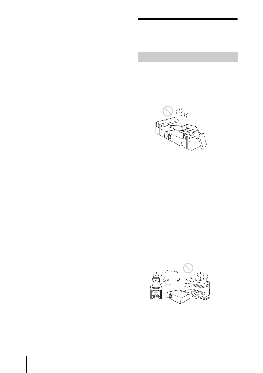
Unsuitable Installation
Do not install the unit in the following
situations. These installations may cause
malfunction or damage to the unit.
Poorly ventilated
• Allow adequate air circulation to prevent
internal heat build-up. Do not place the
unit on surfaces (rugs, blankets, etc.) or
near materials (curtains, draperies) that
may block the ventilation holes.
• When the internal heat builds up due to the
block-up, the temperature sensor will
function with the message “High temp.!
Lamp off in 1 min.” The power will be
turned off automatically after one minute.
• Leave space of more than 30 cm (11
inches) around the unit.
• Be careful that the ventilation holes may
inhale tininess such as a piece of paper.
7
/8
6
Notes on Installation and Usage
Highly heated and humid
• Avoid installing the unit in a location
where the temperature or humidity is very
high, or temperature is very low.
• To avoid moisture condensation, do not
install the unit in a location where the
temperature may rise rapidly.
Subject to direct cool or warm air
from an air-conditioner
Installing in such a location may cause
malfunction of the unit due to moisture
condensation or rise in temperature.
Near a heat or smoke sensor
Malfunction of the sensor may be caused.
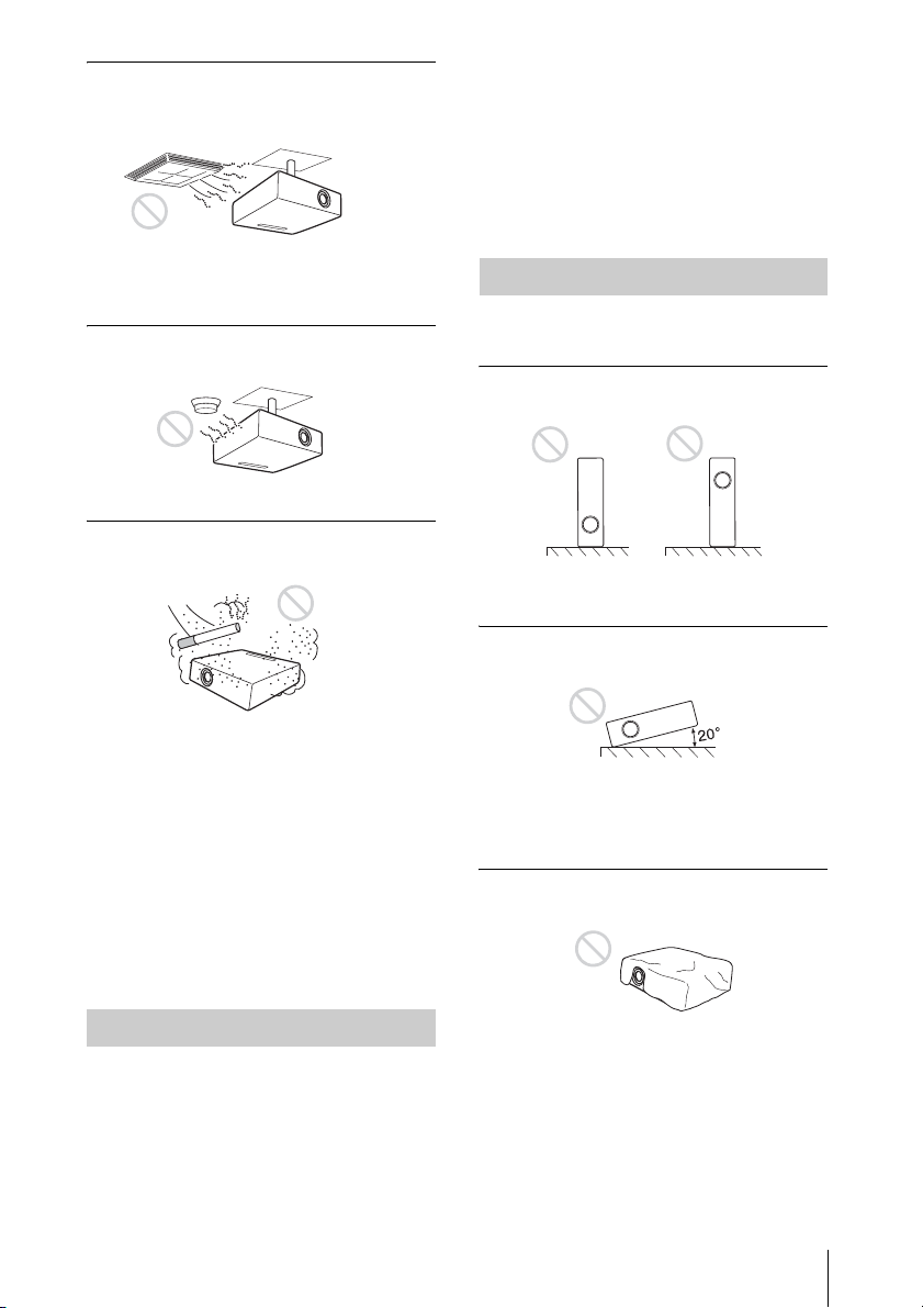
Very dusty, extremely smoky
Note on the screen
When using a screen with an uneven surface,
stripes pattern may rarely appear on the
screen depending on the distance between
the screen and the unit or the zooming
magnifications. This is not a malfunction of
the unit.
Unsuitable Conditions
Do not use the unit under the following
conditions.
Do not topple the unit
Avoid using as the unit topples over on its
side. It may cause malfunction.
Do not tilt right/left
Avoid installing the unit in a very dusty or
extremely smoky environment. Otherwise,
the air filter will become obstructed, and this
may cause a malfunction of the unit or
damage it. Dust preventing the air passing
through the filter may cause a rise in the
internal temperature of the unit. If the
message for replacing the air filter appears,
replace both filters with new ones.
Refer to “Replacing the Air Filters” on page
42 for how to replace.
Usage in High Altitude
When using the unit at an altitude of 1,500 m
or higher, set the “High Altitude Mode” to
“On” in the Setup menu. Failing to set this
mode when using the unit at high altitudes
could have adverse effects, such as reducing
the reliability of certain components.
Avoid using as the unit tilts more than 20
degrees. Do not install the unit other than on
the floor or ceiling. These installations may
cause malfunction.
Do not block the ventilation holes
Avoid using something to cover over the
ventilation holes (exhaust/intake);
otherwise, the internal heat may build up.
Notes on Installation and Usage
7
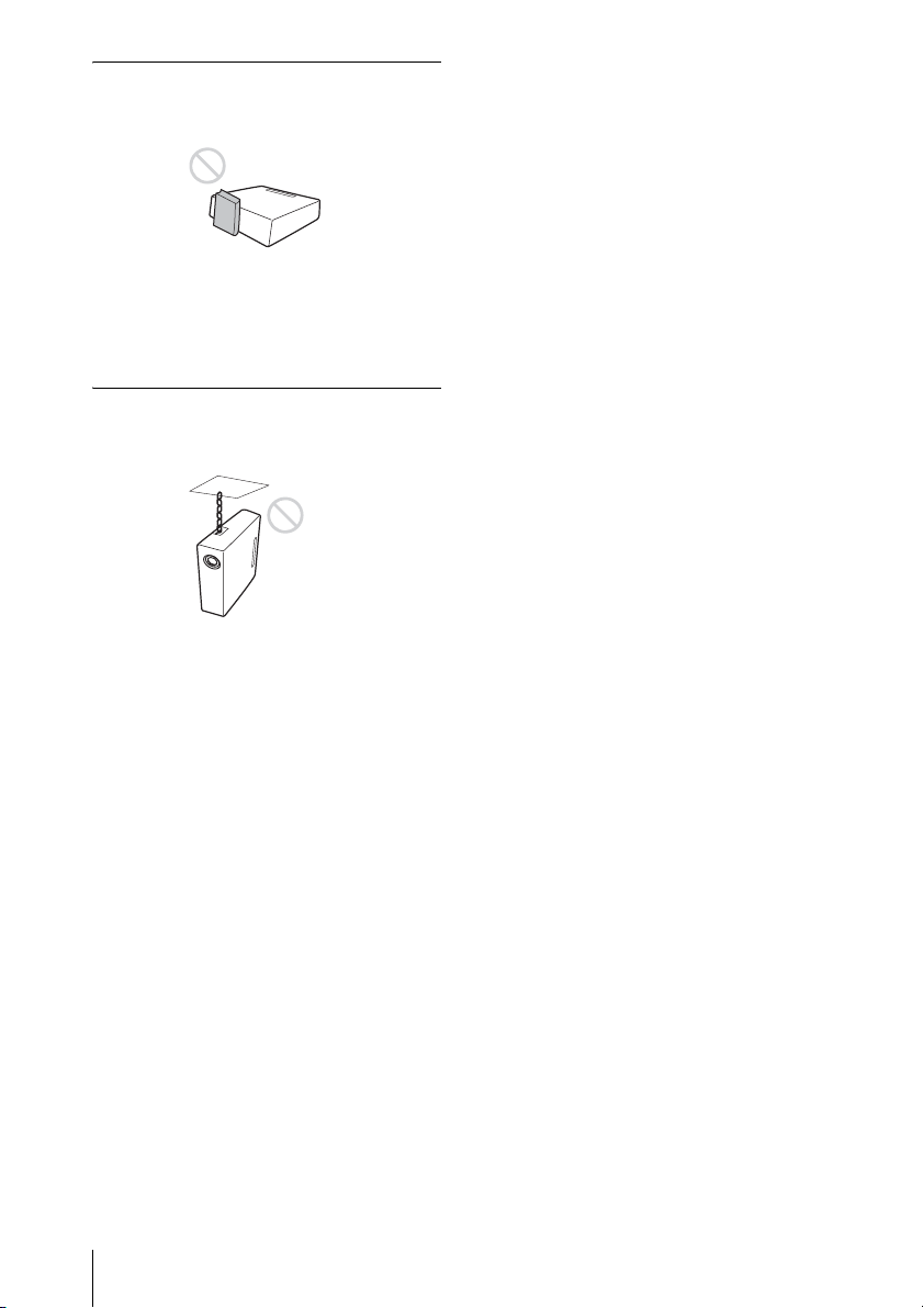
Do not place a blocking object just
in front of the lens
Do not place any object just in front of the
lens that may block the light during
projection. Heat from the light may damage
the object. Use the PIC MUTING key on the
Remote Commander to cut off the picture.
Do not use the Security bar for
transporting or installation
Use the Security bar at the side of the
projector for a purpose of preventing theft,
by attaching a commercially available theft
prevention cable for example. If you lift the
projector by holding the Security bar, or
hang the projector by using this bar, it may
cause the projector to fall or be damaged.
8
Notes on Installation and Usage

B Overview
About the Supplied Manuals
The following manuals and softwares are
supplied with the projector.
On Macintosh system, you can read only the
Operating Instructions and Installation
Manual for Dealers.
Manuals
Safety Regulations (separately
printed manual)
This manual describes important notes and
cautions to which you have to pay attention
when handling and using this projector.
Quick Reference Manual (separately
printed manual)
This manual describes basic operations for
projecting pictures after you have made the
required connections.
Operating Instructions (on the CDROM) (this manual)
This Operating Instructions describes the
setup and operations of this projector.
Software (on the CD-ROM)
Projector Station for Air Shot
Version 2 (Version 2.xx) (Japanese
and English only)
This is an application software for
transmitting data from a computer to the
projector.
The lens is not supplied to this projector. In
this manual, the illustration of the product is
loaded with the optional standard zoom lens
VPLL-Z4019.
Overview
Operating Instructions for Network
(on the CD-ROM)
This Operating Instructions describes how to
set up and operate the network presentation.
Installation Manual for Dealers (on
the CD-ROM)
This manual describes the information for
mounting the optional lenses on the
projector and installing the projector.
Note
You must have Adobe Acrobat Reader 5.0 or
higher is installed to read the Operating
Instructions stored on the CD-ROM.
About the Supplied Manuals
9

Features
High brightness · High picture
performance
High brightness
Sony’s unique optical system with the newgeneration LCD panel “BrightEra”
incorporating a newly developed inorganic
alignment allows a light output of 6000
lumen in VPL-FH300L and 7000 lumen in
VPL-FW300L.
High resolution
VPL-FH300L: Three 2K × 1K panels with
2,210,000 pixels provide a resolution of
2048 × 1080 (horizontal/vertical).
VPL-FW300L: Three WXGA panels with
1,090,000 pixels provide a resolution of
1366 × 800 (horizontal/vertical).
High picture performance
DDE (Dynamic Detail Enhancer)
technology enables conversion of interlace
format video signals to progressive format,
allowing you to obtain a detailed picture.
The technology also reproduces film sources
in 2-3 Pull-Down format with smooth
picture movement. 12-bit 3D Digital
Gamma Correction or 3D Digital Comb
Filter for good picture uniformity is also
provided.
Two-lamp system
Two lamps are equipped. You can select a
desired mode to use two lamps at the same
time or to use one lamp only. When you want
a brighter light or want to use for a long time,
select the appropriate mode.
Stylish round design
The stylish and functional round design
recommends itself as befitting a stylish
interior space.
Convenient and flexible setup
Power zoom/power focus and
horizontal/vertical lens shift function
The projector is equipped with power zoom,
power focus and horizontal/vertical lens
shift function which allows you to change
the size of the projected image with the
Remote Commander operated away from
the projector.
The lens is not supplied with this projector.
No lens is supplied with this projector. You
can select a lens suitable for the installation
condition from among many option lenses.
* Only the manual focus adjusting function is
provided for the optional lens VPLL-4008.
Center positioned lens
The projector is designed to locate the lens
in the center of the projector. This enables
easy setup, as the lens center aligns with the
center of the screen.
Cable management
The control/connector panel section is
covered so that the cables will not be visible.
Tilt installation (at front and rear)
You can install the projector by tilting it 90
degrees at the rear or 90 degrees in front.
You can use a mirror for rear projection.
Direct Power On/Off function
The AC power for the entire system can be
turned on and off by means of a breaker or
other switch.
ID function
The function allows you to adjust or control
each projector individually with one Remote
Commander when you use two or more
projectors (up to three) in one room.
Simple maintenance
Even when the projector is mounted on the
ceiling you can change the lamp, the air
filters or the lens easily because the
replacement lamp is located at the rear of the
projector and the air filters are located at the
side.
10
Features

System expandability and status
check using a network
Connection to a LAN allows you to turn the
projector on/off away from the installation
location via a Web browser or to obtain
projector status information such as the lamp
timer.
Also, this projector enables the sending of
mail that contains messages on the time for
replacement of the projector lamp, error
occurrences, etc., to mail addresses that have
been specified. Also, this projector is
available for SNMP or PJLink.
Multi scan compatibility
5BNC and HDMI connectors
The projector has the HDMI (HighDefinition Multimedia Interface) connector,
a digital input connector, which allows you
to connect to digital RGB equipment
equipped with HDMI output. The 5BNC
input connectors allow you to connect to
equipment output high-resolution signals
and to a computer from a long distance.
Accepts various input signals
The projector accepts video signals of the
composite, S video and component, and can
also display VGA, SVGA, XGA, WXGA,
SXGA, SXGA+, WSXGA+, UXGA, Full
HD and 2K × 1K (24Hz) signals.
About Trademarks
• Adobe Acrobat is a trademark of Adobe
Systems Incorporated.
• Windows is a registered trademark of
Microsoft Corporation in the United States
and/or other countries.
• Kensington is a registered trademark of
Kensington Technology Group.
• Macintosh is a registered trademark of
Apple Computer, Inc.
• VESA is a registered trademark of the
Video Electronics Standards Association.
• Display Data Channel is a trademark of the
Video Electronics Standards Association.
• HDMI, HDMI logo and High-Definition
Multimedia Interface are trademarks or
registered trademarks of HDMI Licensing
LLC.
• Air Shot is a trademark of Sony
corporation.
• “BrightEra” is a trademark of Sony
corporation.
• All other trademarks and registered
trademarks are trademarks or registered
trademarks of their respective holders. In
this manual, ™ and ® marks are not
specified.
Overview
Network presentation
Any image of a computer, if it is connected
to a LAN by wired or wireless connection,
can be projected by connecting a network
cable to the NETWORK connector (RJ45)
of the projector. For details, see the
“Operating Instructions for Network”.
Other Convenient Functions
• Security lock
• Panel key lock
• Easy-to-use Remote Commander that can
select the input source directly
• On-screen menu in 16 languages
• Picture muting
•Freeze
• Lamp mode switching function
• Antitheft bar
• Equipped with Standby Mode “Low”
Features
11
Location and Function of Controls
1
ABC
2
98 0
1
ABC
2
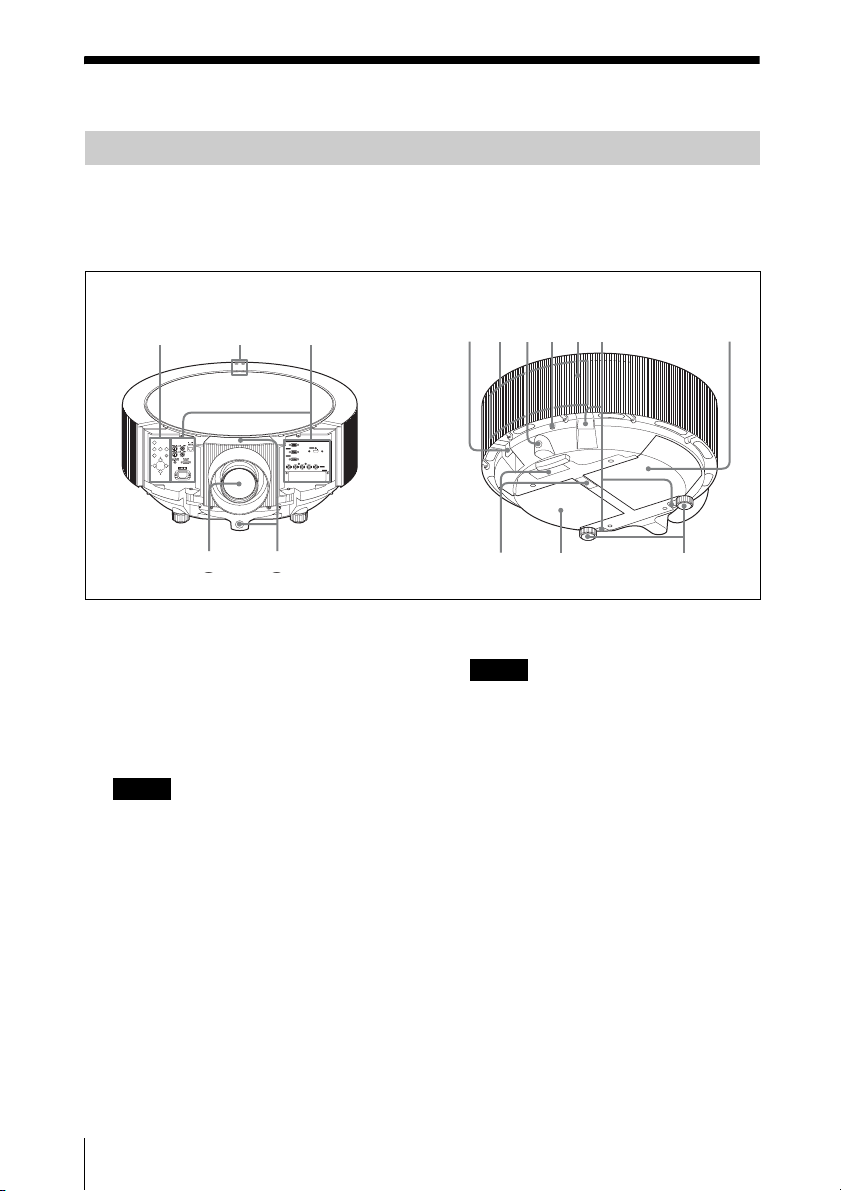
Main unit
• The lens is not supplied with this projector. In the illustrations in this manual, the product is
loaded with the optional standard zoom lens VPLL-Z4019.
• The covers on the left and right of the lens are removed in the illustration. Refer to “To
remove the connector covers” on page 21 for how to remove the covers.
Top/Front/Side Rear/Side/Bottom
345673 8
INPUT
INPUT
SHIFT
ZOOM FOCUS
SHIFT
ZOOM FOCUS
MENU ENTER
MENU ENTER
RGB
INPUT A
RGB
INPUT A
HDMI
INPUT D
INPUT B
RGB
HDMI
INPUT D
INPUT B
RGB
OUTPUTMONITOR
OUTPUTMONITOR
R/R-Y/P
R B/B-Y/PB HD VDG/Y
R/R-Y/P
R B/B-Y/PB HD VDG/Y
INPUT C
INPUT C
INPUT E
INPUT E
a Lens
The lens is not supplied with this
projector. Attach an optional lens to suit
your conditions of use or purpose.
Regarding the attachable optional
lenses, consult with qualified Sony
personnel.
Note
Be sure to remove the lens cap before
projection. If not, heat may cause the cap to
melt.
To mute the picture temporarily, press the
MUTING PIC button on the Remote
Commander.
b Front remote control detector
c Security bar (four)
An anti-theft chain or wire
(commercially available) can be
connected to it.
12
Location and Function of Controls
d Ventilation holes (exhaust)
Notes
• Do not place anything near the
ventilation holes as this may cause
internal heat build-up.
• Do not place your hand near the
ventilation holes as this may cause
injury.
e Rear remote control detector
f Security lock
Connects to an optional security cable
(from Kensington).
Web page address:
http://www.kensington.com/
g Lamp cover
h Air filter covers/Ventilation
holes (intake)
Two filters are attached internally.

Note
If the message for replacing the air filter
appears, replace, both air filters with new
ones to maintain the optimal performance
of the projector.
For details, see “Replacing the Air
Filters” on page 48.
i Ventilation holes (intake)
j Adjusters
Turn the appropriate adjuster to the right
or left for minor tilt adjustment of the
projected picture.
A Control Panel
For details, see “A Control Panel”.
B Power/Indicator
For details, see “B Power Indicator”
on page 14.
C Connector Panel
For details, see “C Connector Panel”
on page 15.
A Control Panel
1
2
3
INPUT
SHIFT
ZOOM FOCUS
MENU ENTER
4
5
6
7
position of the picture using the arrow
keys. Press the V key to move the picture
upward. Press the v key to move it
downward. Press the B key to move it
leftward. Press the b key to move it
rightward.
Note
Do not perform the lens shift operation
when the optional lens VPLL-4008 is
attached to the projector because the
projector is installed with the center of the
lens aligned with the center of the screen.
c MENU key
Displays the on-screen menu. Press
again to clear the menu.
d ZOOM key
Enters the zoom adjustment mode. Next,
adjust the picture size using the arrow
keys. Press the V or b key to enlarge the
picture size, and the v or B key to reduce
it.
e FOCUS key
Enters the focus adjustment mode. Next,
adjust the focus using the arrow keys.
Press the V or b key to focus on a picture
further back, and the v or B key to focus
on a picture further forward.
The ZOOM and FOCUS keys cannot be
used when you attach the optional lens
VPLL-4008 to the projector.
f ENTER key
Used to enter the settings of items in the
menu system.
g V/v/B/b (Arrow) keys
Used to select a menu, or make various
adjustments.
Overview
a INPUT key
Select the input signal. Each time you
press the key the input signal switches.
b SHIFT key
Enters the H/V shift adjustment mode.
Next, adjust the vertical/horizontal
Location and Function of Controls
13
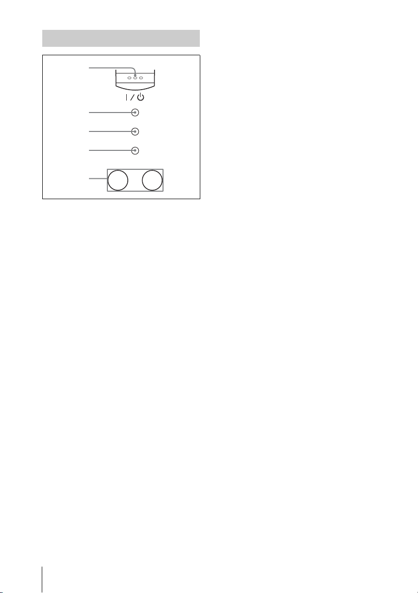
B Power/Indicator
For details, see the “Turning Off the
Power” on page 27 and “Replacing the
Lamp (s)” on page 46.
1
2
ON/STANDBY
3
PIC MUTING
4
LAMP/COVER
12
LAMP
5
a ?/1 (On/Standby) key
Turns on the projector when it is in
standby mode. When you push this key,
the ON/STANDBY indicator flashes in
green and then lights in green when the
projector is ready to operate.
To turn off the power, press the ?/1 key
twice according to the message or hold
the ?/1 key for about one second.
b ON/STANDBY indicator
Lights up or flashes under the following
conditions:
• Lights in red when the AC power cord
is plugged into a wall outlet. Once the
projector is in standby mode, you can
turn it on with the ?/1 key.
• Flashes in red when the internal
temperature is high or the electrical
system has failed.
• Lights in green when the projector is
turned on, and when it is ready to
operate.
• Flashes in green from the time when
the projector is turned on until the
projector is ready to operate. Also,
flashes in green while the cooling fan
is running after the power is turned off
with the ?/1 key. The fan runs for
about 90 seconds after the power is
turned off.
• Lights in orange when the power
saving mode is on.
c PIC MUTING (picture muting)
indicator
Shows that the picture is muted by
pressing the MUTING PIC button on the
Remote Commander when this indicator
is lighting in orange.
There are two muting modes in this
projector. The image muting mode
mutes the image signal, and the shutter
muting mode cuts the projecting picture
by the shutter inside the lens. The picture
is muted by the mode selected in the
“Picture Muting Mode” of the Setup
menu.
For details, see the “PIC (Picture)
Muting Mode” on page 38.
d LAMP/COVER indicators
Flashes in orange under the following
conditions:
• A reception rate of 2 flashes when
the lamp cover or air filter cover is not
secured firmly.
• A reception rate of 3 flashes when
the lamp has reached the end of its life
or reaches a high temperature.
• A reception rate of 4 flashes when
the shutter does not work properly.
Note that it does not flash when the
shutter is open.
For details, see “Replacing the
Lamp (s)” on page 46.
e LAMP1, 2 indicators
Shows the lamp which has not lit.
• LAMP1 lights in orange when
LAMP1 has not lit.
• LAMP2 lights in orange when
LAMP2 has not lit.
• Both LAMP1 and 2 light on orange
when LAMP1 and LAMP2 have not
lit.
For details, see “The Installation Menu”
on page 42.
14
Location and Function of Controls
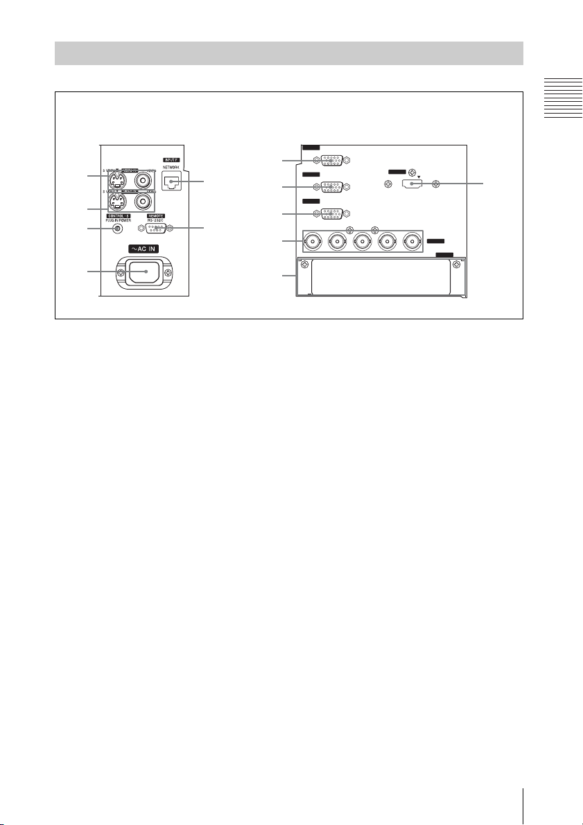
C Connector Panel
On the left of the lens On the right of the lens
RGB
INPUT A
1
2
3
5
6
7
8
9
INPUT B
RGB
OUTPUT MONITOR
R/R-Y/P
R B/B-Y/PB HD VDG/Y
INPUT D
0
4
qa
Overview
HDMI
qs
INPUT C
INPUT E
a VIDEO IN (Video input)
Connects to external video equipment.
S VIDEO (mini DIN 4-pin)
Connects to the S video output (Y/C
video output) of video equipment.
VIDEO (BNC jack)
Connects to the composite video output
of video equipment.
b VIDEO OUT (Video output)
S VIDEO (mini DIN 4-pin)
Used as loop-through output via the S
VIDEO IN connector.
VIDEO (BNC jack)
Used as loop-through output via the
VIDEO IN connector.
c CONTROL-S/PLUG IN POWER
(DC 5V output) jack (stereo
minijack)
Connects to the control S out jacks of
Sony equipment. Connects to the
CONTROL S OUT jack on the supplied
Remote Commander when using it as a
wired Remote Commander. In this case,
when a stereo cable is used, you do not
need to install batteries in the Remote
Commander as the power is supplied
from this jack.
d AC IN socket
Connects the supplied AC power cord.
Be sure to attach the supplied AC
connector cover.
e INPUT F
NETWORK connector (RJ-45)
Connects to the LAN cable when the
network function is in use.
CAUTION
For safety, do not connect the co nnector for
peripheral device wiring that might have
excessive voltage to this port.
Follow the instructions for this port.
f REMOTE/RS-232C connector
(D-sub 9-pin, female)
Connects to a computer to operate the
projector from the computer.
7/8 INPUT A/INPUT B
Analog RGB connector (HD D-sub
15-pin, female)
Connects to external equipment such as
a computer.
Connects to the monitor output of a
computer using an optional cable.
Location and Function of Controls
15
9 OUTPUT
q
MONITOR connector (HD D-sub
15-pin, female)
Connect to the video input connector of
the monitor. Outputs signals from the
selected channel and computer signals
only from among the signals from the
INPUT A, INPUT B or INPUT C.
This connector does not output any
signals from the INPUT D connector.
q; INPUT C
Analog RGB/Component
connectors (R/R-Y/P
B, HD, VD) (BNC type)
P
R, G/Y, B/B-Y/
Connect to a high-resolution computer
or VCR where signals are transmitted
long distances, for example, when the
projector has been hung from the
ceiling.
Computer, component (R-Y/Y/B-Y),
HDTV or DTV (DTV GBR, DTV
BPR) signal can be selected.
YP
qa INPUT E
Sony HD-SDI/SDI Input Adaptor can be
attached to this connector.
Regarding the attachable optional
boards, consult the technical
information center.
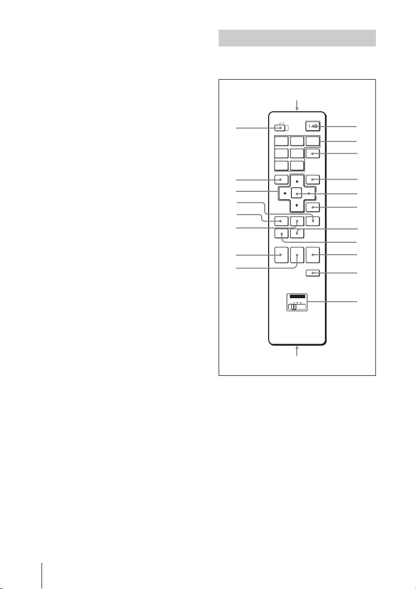
Remote Commander
The keys that have the same names as those
on the control panel function identically.
wa
COMMAND
w;
ql
qk
qj
qh
qg
qf
qd
OFF ON
INPUTBINPUT
INPUT
A
INPUT
INPUT
D
E
VIDEO
S VIDEO
MENU APA
ENTER
KEY
ASPECT
STONE
D ZOOM MUTING
PIC
+
AUDIO
–
ID MODE
1 2 3
AIR
SHOT
RESET
SHIFTZOOMFOCUS
VOLUME
FREEZE
C
+
–
1
2
3
4
5
6
7
8
9
0
qa
qs INPUT D
Digital RGB/Component
connector (HDMI) (accepts HDCP)
Connects to a video output connector on
video equipment or a computer
equipped with HDMI/DVI output
connector (digital).
16
Location and Function of Controls
s
a ?/1 (On/Standby) key
b INPUT A/B/C/D/E keys
Selects the input signal output from the
connector of the same name as those of
the Remote Commander.
c AIR SHOT key
Displays the Network Presentation
Home (INPUT F).
For details, see Operating Instructions
for Network (stored on the CD-ROM).
d APA (Auto Pixel Alignment) key
Automatically adjusts a picture to its
clearest while a signal is input from a
computer.

For details, see “APA” in “The Screen
Menu” on page 37.
e ENTER key
f RESET key
Resets the value of an item to its factory
preset value. This key functions when a
setting item is displayed on the screen.
g KEYSTONE (Vertical trapezoidal
distortion correction) key
Adjusts the vertical trapezoidal
distortion of the image manually. When
you press this key, the V Keystone menu
is displayed. Use the arrow keys (M/m/
</,) for adjustment.
h ASPECT key
Select the aspect ratio of the picture.
Each time you press this key the aspect
ratio changes according to the input
signals.
i VOLUME +/– keys
This function is not provided in this
projector.
j FREEZE key
Freezes the projected picture. To cancel
the frozen picture, press the key again.
k ID MODE 1/2/3 keys
When you apply the same identification
number as the projector to a Remote
Commander you can easily adjust or
control each projector with a Remote
Commander whenever you use two or
more projectors in one room.
For details, see “ID Mode” in the
Installation menu on page 43.
l CONTROL S OUT jack (stereo
mini-jack)
Connects to the CONTROL S IN jack on
the projector with the connecting cable
(not supplied) when using the Remote
Commander as a wired one. In this case
you do not need to install the batteries
since the power is supplied via the
CONTROL S IN jack on the projector.
m MUTING keys
• PIC: Cuts off the picture. Press again
to restore the picture.
When the MUTING key is in action,
the PIC MUTING indicator on the top
of the main unit lights.
There are two muting modes in this
projector. The image muting mode
mutes the image signal, and the shutter
muting mode cuts the projecting
picture by the shutter inside the lens.
The picture is muted by the mode
selected in the “Picture Muting
Mode” of the Setup menu.
For details, see “PIC (Picture) Muting
Mode” on page 38.
• AUDIO: This function is not provided
in this projector.
n D ZOOM (Digital Zoom) +/– key
This function is not provided in this
projector.
o ZOOM +/– keys
Adjusts the picture size.
p FOCUS +/– keys
Adjusts the picture focus.
q SHIFT +/– keys
Adjusts the vertical/horizontal position
of the picture.
r M/m/</, keys (Arrow)
Used to enter the settings of items in the
menu or make adjustment for zoom,
focus or shift.
s MENU key
t COMMAND ON/OFF switch
When this switch is set to OFF, the keys
on the Remote Commander do not
function. This saves battery power.
u Infrared transmitter
To install batteries
1 Push and slide the lid to open it, then
install the two size AA (R6) batteries
(supplied) with the correct polarity.
Overview
Location and Function of Controls
17
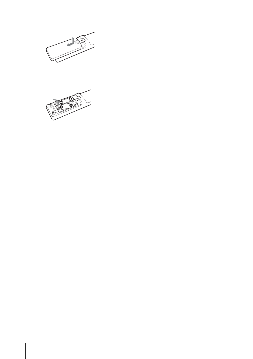
While pressing the lid, slide it.
Be sure to install the batter y from
# side.
the
2 Replace the lid.
Notes on Remote Commander
operation
• Make sure that nothing obstructs the
infrared beam between the Remote
Commander and the remote control
detector on the projector. Direct the
Remote Commander toward the front or
rear remote control detector.
• The operation range is limited. The shorter
the distance between the Remote
Commander and the projector is, the wider
the angle within which the commander can
control the projector becomes.
18
Location and Function of Controls
B Projecting the Picture
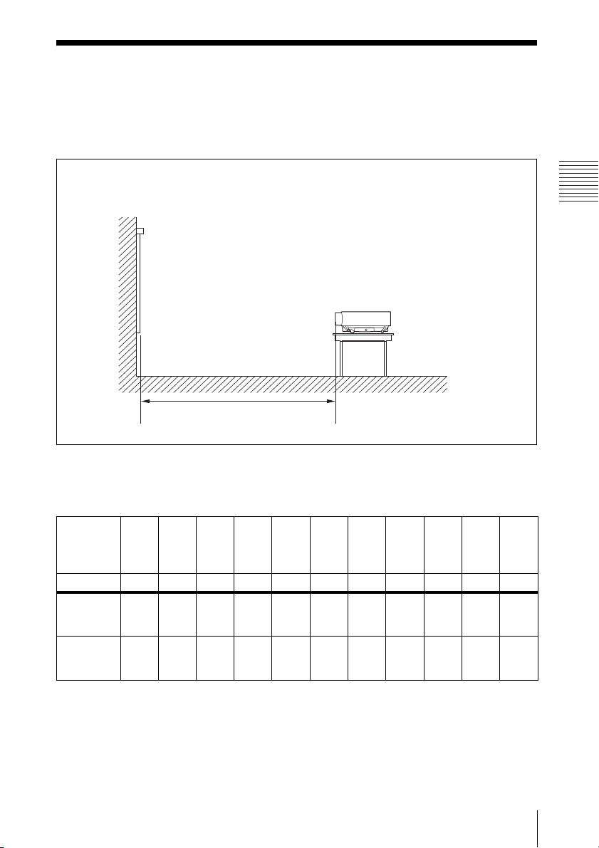
Installing the Projector
The following table gives an example of installing the optional standard zoom lens VPLLZ4019 is attatched to the VPL-FH300L/FW300L.
For details on installation, ceiling installation or when you use an other optional lens, be sure
to consult with qualified Sony personnel.
The distance between the lens and the screen varies depending on the size of the projection
image. Use the following table as a guide.
Screen
Distance between the screen
and the center of the lens
Projecting the Picture
VPL-FH300L
(When “Aspect” on the Screen menu is set to “Full 2” or “Full”)
Unit: m (feet)
Projected
40 60 80 100 120 150 200 300 400 500 600
image size
(diagonal)
(inches)
(mm) 1016 1524 2032 2540 3048 3810 5080 7620 10160 12700 15240
Minimum
Distance
Maximum
Distance
1.7
(67)
2.2
(86
5
/8)
2.6
(102
3
/8)
3.3
(130)
3.5
(137
7
/8)
4.4
(173
1
/4)
4.3
(169
3
/8)
5.6
(220
1
/2)
5.2
(204
3
/4)
6.7
(264
7
/8)
6.6
(259
7
/8)
8.4
(330
3
/4)
8.8
(346
1
/2)
11.2
(441)
13.3
(523
3
/4)
16.9
(665
1
/2)
17.8
(700
1
/2)
22.6
(889
7
/8)
22.2
(874
1
/8)
28.2
(1109
1
/8)
26.7
(1051
3
/8)
33.9
(1334
1
/2)
There may be a slight difference between the actual value and the design value shown in the table
above.
Installing the Projector
19
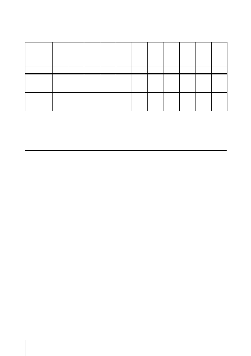
VPL-FW300L
(When “Aspect” on the Screen menu is set to “Full 2” or “Full”)
Unit: m (feet)
Projected
40 60 80 100 120 150 200 300 400 500 600
image size
(diagonal)
(inches)
(mm) 1016 1524 2032 2540 3048 3810 5080 7620 10160 12700 15240
Minimum
Distance
Maximum
Distance
1.6
(63)
2.1
(82
3
/4)
2.5
(98
1
/2)
3.2
(126)
3.4
(133
7
/8)
4.3
(169
3
/8)
4.2
(165
3
/8)
5.4
(212
5
/8)
5.1
(200
7
/8)
6.5
(256)
6.4
(252)
8.2
(322
7
/8)
8.6
(338
5
/8)
10.9
(429
1
/4)
12.9
(508)
16.5
(649
3
/4)
17.3
(674
1
/4)
22.0
(866
1
/4)
21.7
(854
1
/2)
27.5
(1082
7
/8)
26.0
(1023
5
/8)
33.1
(1303
3
/8)
There may be a slight difference between the actual value and the design value shown in the table
above.
For details on installation, consult with qualified Sony personnel.
V-Keystone
The V-Keystone correction (keystone distortion vertical correction) function can correct a
picture distortion due to projecting angle.
See the “The Installation Menu” on page 42 for details of setting.
Correcting angle
VPL-FH300L: ±5° (±15° when using the video signal only)
VPL-FW300L: ±30° (±10° at 1080/24p and 1080/30p)
20
Installing the Projector
Connecting the Projector
When you connect the projector,
make sure to:
• Turn off all equipment before making any
connections.
• Use the proper cables for each connection.
• Insert the cable plugs firmly; loose
connections may increase noise and
reduce performance of picture signals.
When pulling out a cable, be sure to pull it
out by the plug, not the cable itself.
When connecting to a LAN using a LAN
cable, see “Operating Instructions for
Network” stored on the CD-ROM.
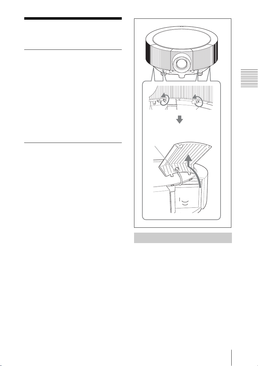
To remove the connector covers
Before connection, remove the connector
covers on both sides of the lens.
First remove the two screws on the bottom of
each connector cover, and then lift up the
bottom side of the cover as in the illustration.
The connector covers are connected with the
main unit by the fall-prevention wires.
INPUT
SHIFT
ZOOM FOCUS
MENU ENTER
Fall-prevention
wire
RGB
INPUT A
HDMI
INPUT D
INPUT B
RGB
OUTPUTMONITOR
R/R-Y/P
R B/B-Y/PB SYNC/HD VDG/Y
INPUT C
INPUT E
Projecting the Picture
Connecting a Computer
This section describes how to connect the
projector to a computer.
For more information, refer to the
computer’s instruction manual.
Connecting the Projector
21
 Loading...