

Sony vpl-fw300L User Manual
3-270-756-01 (1)
Data Projector
特約店様用設置説明書 2 〜 12、59 〜 75 ページ
この特約店様用設置説明書には、レンズの取り付け方法、別売のレンズ使用時や天井吊りの場合
の設置寸法など、製品の設置時に必要な情報を記載しています。
お客様へ
この設置説明書は、特約店様用に書かれたものです。
お客様が設置説明書に記載された設置を行うと、事故などにより死亡や大けがにつながることが
あります。お客様自身では絶対に設置をしないでください。設置については必ずソニーテクニカ
ルインフォメーションセンターにご相談ください。
特約店の方は、設置を安全に行うために、必ずこの説明書をよくお読みください。
Installation Manual for Dealers Pages 13 to 19 and 59 to 75
This Installation Manual for Dealers explains how to install the projector. For example, it
explains lens attachment, installation measurements when using the optional lens and
hanging the projector from the ceiling.
Warning: This Installation Manual is for Dealers.
Manuel d’installation pour revendeurs Pages 20 à 27 et 59 à 75
Ce Manuel d’installation pour revendeurs explique comment installer le projecteur. Par
exemple, il décrit comment fixer l’objectif, fournit les mesures d’installation lors de l’utilisation
de l’objectif en option et explique comment installer le projecteur au plafond.
Avertissement: Ce Manuel d’installation s’adresse aux revendeurs
Manual de instalación para proveedores, Páginas 28 a 35 y 59 a 75
En este manual de instalación para proveedores se describe cómo instalar el proyector. Por
ejemplo, se describe cómo sustituir el objetivo, las medidas de instalación cuando se utiliza
el objetivo opcional y cómo colgar el proyector en el techo.
Advertencia: Este manual de instalación es para proveedores.
Installationsanleitung für Händler Seite 36 bis 43 und Seite 59 bis 75
In dieser Installationsanleitung für Händler wird die Installation des Projektors beschrieben.
Zum Beispiel wird auf das Anbringen des Objektivs, die Installationsabmessungen bei
Verwendung optionaler Objektive und bei Deckenmontage des Projektors eingegangen.
Warnung: Diese Installationsanleitung ist nur für Händler bestimmt.
Manuale di installazione per rivenditori Pagine da 44 a 51 e da 59 a 75
Questo manuale di installazione per rinvenditori illustra la procedura di installazione del
proiettore. Ad esempio, illustra il montaggio degli obiettivi, le misure di installazione durante
l’utilizzo di obiettivi opzionali e come installare il proiettore a sospensione su soffitto
Avvertenza: Questo manuale di installazione è per rivenditori.
VPL-FH300L
VPL-FW300L
© 2007 Sony Corporation
日本語
安全のために
ソニー製品は安全に充分配慮して設計されています。し
かし、電気製品は、まちがった使いかたをすると、火災
や感電などにより死亡や大けがなど人身事故につながる
ことがあり、危険です。
事故を防ぐために次のことを必ずお守りください。
安全のための注意事項を守る
注意事項をよくお読みください。
定期点検をする
5 年に 1 度は、内部の点検を、テクニカルインフォメー
ションセンターにご相談ください(有料)。
故障したら使用を中止する
すぐにテクニカルインフォメーションセンターにご連絡
ください。
万一、異常が起きたら
・ 煙が出たら
・ 異常な音、においがしたら
・ 内部に水、異物が入ったら
・ 製品を落としたり、キャビネットを破損したと
きは
警告表示の意味
この説明書および製品では、次のような表示をし
ています。表示の内容をよく理解してから本文を
お読みください
この表示の注意事項を守らないと、火災や感電な
どにより死亡や大けがなど人身事故につながるこ
とがあります。
この表示の注意事項を守らないと、感電やその他
の事故によりけがをしたり周辺の物品に損害を与
えたりすることがあります。
注意を促す記号
v
a 電源を切る。
b 電源コードや接続ケーブルを抜く。
c テクニカルインフォメーションセンターに連絡する。
行為を禁止する記号
行為を指示する記号
2
目次
警告................................................................................4
注意................................................................................5
本機の性能を保持するために .............................................7
概要 ........................................................................................ 8
レンズの取り付けかた ........................................................8
レンズを取り付ける........................................................................8
レンズを交換する .............................................................................9
HD-SDI/SDI 入力アダプターの取り付けかた .............10
設置寸法 ............................................................................ 11
床置き....................................................................................................... 11
天井つり................................................................................................ 11
プロジェクターサスペンションサポート PSS-630 の
取り付けかた.....................................................................................11
床置き、ツインスタック.......................................................... 12
プロジェクターの外形寸法 ......................................................12
設置寸法..............................................................................59
床置き .....................................................................................................59
天井つり................................................................................................ 63
PSS-630 の取り付けかた ........................................................... 67
ツインスタック................................................................................68
寸法図 ................................................................................72
目次
3
警告
排気口、吸気口をふさぐような場所
に設置しない
排気口、吸気口をふさぐと内部に熱がこも
り、火災や故障の原因となることがありま
す。風通しをよくするために次の項目をお
守りください。
・ 壁から 30cm 以上離して設置する。
・ 密閉された狭い場所に押し込めない。
・ 毛足の長い敷物(じゅうたんや布団など)
の上に設置しない。
・ 布などで包まない。
天井への取り付けには細心の注意を
はらう
・ 天井への取り付け強度が不充分だと、落
下により死亡や大けがにつながることが
あります。必ずソニー製のプロジェク
ターサスペンションサポート PSS-630 を
使用してください。
・ 天井への取り付け時は、付属のダストカ
バーを必ず取り付けてください。
・ 取り付けを安全に行うために、本書、CD-
ROM 内の取扱説明書および PSS-630 の取
付説明書の注意事項をお読みください。
・ 取り付けは、PSS-630 の取付説明書の手
順に従い確実に行ってください。取り付
けが不完全な場合、落下する可能性があ
ります。
また、取り付け時には手をすべらせてプ
ロジェクターを落下させ、けがをするこ
とのないようご注意ください。
熱感知器や煙感知器のそばに設置し
ない
熱感知器や煙感知器のそばに設置すると、
排気の熱などにより、感知器が誤動作する
など、思わぬ事故の原因となることがあり
ます。
ランプ交換はランプが充分に冷えて
から行う
電源を切った直後はランプが高温になって
おり、さわるとやけどの原因となることが
あります。ランプ交換の際は、電源を切っ
てから1時間以上たって、充分にランプが
冷えてから行ってください。
調整用工具を内部に入れない
調整中などに、工具を誤って内部に落とす
と火災や感電の原因となることがあります。
万一、落とした場合は、すぐに電源を切り、
電源コードを抜いてください。
指定された部品を使用する
指定以外の部品を使用すると、火災や感電
および故障や事故の原因となります。ラン
プ、電池、天吊り金具、レンズ、フィルタ
は指定されたものを使用してください。
付属の電源コードを使う
付属の電源コードを使わないと、火災や感
電の原因となることがあります。
電源コードを傷つけない
電源コードを傷つけると、火災や感電の原
因となることがあります。
・ 設置時に、製品と壁やラック、棚などの
間に、はさみ込まない。
・ 電源コードを加工したり、傷つけたりし
ない。
・ 重いものをのせたり、引っ張ったりしな
い。
・ 熱器具に近づけたり、加熱したりしない。
・ 電源コードを抜くときは、必ずプラグを
持って抜く。
万一、電源コードが傷んだら、テクニカル
インフォメーションセンターに交換をご相
談ください。
電源コードのプラグおよびコネク
ターは突きあたるまで差し込む
まっすぐに突きあたるまで差し込まないと、
火災や感電の原因となります。
容量の低い電源延長コードを使用し
ない
容量の低い延長コードを使うと、ショート
したり火災や感電の原因となることがあり
ます。
警告
4
注意
安全アースを接続する
安全アースを接続しないと、感電の原因と
なることがあります。プラグから出ている
緑色のアースを、建物に備えられている
アース端子に接続してください。
天吊り状態でレンズ交換をしない
天吊り状態で作業をすると、レンズを取り
落としたりして、けがや事故の原因となり
ます。
レンズ交換後はレバーを必ずロック
する
半ロックの状態に放置すると、レンズ落下
により事故の原因となります。
レンズをのぞかない
投影中にプロジェクターのレンズをのぞく
と光が目に入り、目に悪影響を与えるおそ
れがあります。
プロジェクターにぶら下がらない
落下してけがの原因となります。
ランプ交換時、ランプカバーにラン
プや工具を置かない
ランプカバーにランプや工具を置くと、そ
れらが落ちたりして、けがの原因となるこ
とがあります。
不安定な場所に設置しない
ぐらついた台の上や傾いたところに設置す
ると、倒れたり落ちたりしてけがの原因と
なります。また、設置・取り付け場所の強
度を充分にお確かめください。
運搬・移動は慎重に
・ 床置きのプロジェクターを移動させると
き、本体と設置面との間に指を挟まない
ようにご注意ください。
・ キャビネットのカバーを開けたまま、電
源を切らずに移動させないでください。
感電の原因となることがあります。
アジャスター調整時に指を挟まない
アジャスターの調整は慎重に行ってくださ
い。そうしないと、アジャスターに指を挟
み、けがの原因となることがあります。
運搬するときは必ず左右側面を 2 人
で持つ
運搬するときは、必ず左右側面のくぼみを
2 人で持ってください。他の部分を持つと
プロジェクターが壊れたり、落してけがを
することがあります。
床置きのプロジェクターを移動させるとき、
本体と設置面との間に指を挟まないようご
注意ください。
本機を立てて置かない
保管や一時的に立てておくと倒れて思わぬ
事故の原因になり危険です。
注意
5
コード類は正しく配置する
電源コードや接続コードを足に引っかける
と転倒したり、プロジェクターの落下によ
りけがの原因となることがあります。充分
注意して接続・配置してください。
低い天井に天吊りしない
頭などをぶつけてけがをすることがありま
す。
キャビネットのカバー類はしっかり
固定する
天吊りの場合、カバー類が固定されていな
いと落下して、けがの原因となることがあ
ります。
水のある場所に置かない
水が入ったり、濡れたり、風呂場などで使
うと、火災や感電の原因となります。雨天
や降雪中の窓際でのご使用や、海岸、水辺
でのご使用は特にご注意ください。
湿気やほこり、油煙、湯気の多い場
所や虫の入りやすい場所、直射日光
が当たる場所、熱器具の近くに置か
ない
火災や感電の原因となることがあります。
レンズシフト調整時に指を挟まない
レンズシフトに指を挟まないように注意し
てください。けがの原因となることがあり
ます。
製品の上にものを載せない
製品の上にものを載せると、故障や事故の
原因となります。
不明な点はテクニカルインフォメーションセンターにご
相談ください。
注意
6

本機の性能を保持するた
めに
設置場所について
・ 吸気口および排気口は、内部の温度上昇を防ぐためのも
のです。風通しの悪い場所を避け、吸気口および排気口
をふさがないように設置してください。
・ 温度・湿度が非常に高い場所や温度が著しく低い場所、
ほこりの多い場所での使用は避けてください。
・ 床置きおよび天井つり以外の設置でお使いになると、色
むらやランプ寿命の劣化などの問題が起こることがあり
ますので避けてください。
ファンの音について
プロジェクターの内部には温度上昇を防ぐためにファン
が取り付けられており、電源を入れると多少音を生じま
す。これらは液晶プロジェクターの構造によるもので故
障ではありません。しかし、異常音が発生した場合には
テクニカルインフォメーションセンターにご相談くださ
い。
部屋の照明について
直射日光や室内灯などで直接スクリーンを照らさないで
ください。美しく見やすい画像にするために、以下の点
を参考にしてください。
・ 集光型のダウンライトにする。
・ 蛍光灯のような散光照明にはメッシュを使用する。
・ 太陽の差し込む窓はカーテンやブラインドでさえぎる。
・ 光を反射する床や壁はカーペットや壁紙でおおう。
・ 汚れがひどいときは、クリーニングクロスやメガネ拭き
などの柔らかい布に水を少し含ませて、拭きとってくだ
さい。
・ アルコールやベンジン、シンナー、酸性洗浄液、アルカ
リ性洗浄液、研磨剤入り洗浄剤、化学ぞうきんなどはレ
ンズ表面を傷めますので、絶対に使用しないでくださ
い。
外装のお手入れについて
・ 乾いた柔らかい布で軽く拭いてください。汚れがひどい
ときは、薄い中性洗剤溶液を少し含ませた布で拭きと
り、乾いた布でカラ拭きしてください。
・ アルコールやベンジン、シンナー、殺虫剤をかけると、
表面の仕上げを傷めたり、表示が消えてしまうことがあ
るので、使用しないでください。
・ 布にゴミが付着したまま強く拭いた場合、傷が付くこと
があります。
・ ゴムやビニール製品に長時間接触させると、変質した
り、塗装がはげたりすることがあります。
結露について
プロジェクターの設置してある室内の急激な温度変化は
結露を引き起こし、故障の原因となりますので冷暖房に
ご注意ください。
結露とは、寒いところから急に暖かい場所へ持ち込んだ
とき、本体の内部に水滴がつくことです。結露が起きた
ときは、電源を入れたまま本機をそのまま約 2 時間放置
しておいてください。
お手入れのしかた
お手入れをする前に、必ず電源プラグをコンセントから
抜いてください。
エアーフィルターの交換について
エアーフィルター交換のメッセージが表示されたら、2 つ
とも新しいものと交換してください。
◆交換方法については、取扱説明書のエアーフィル
ターを交換するをご参照ください。
レンズ面のお手入れについて
レンズの表面は反射を抑えるため、特殊な表面処理を施
してあります。誤ったお手入れをした場合、性能を損な
うことがありますので、以下のことをお守りください。
・ レンズに手を触れたり、固いもので傷をつけたりしない
ようにご注意ください。
・ レンズ表面についた汚れは、クリーニングクロスやメガ
ネ拭きなどの柔らかい布で軽く拭いてください。
本機の性能を保持するために
7
概要
レンズの取り付けかた
この説明書は、ソニーデータプロジェクター
VPL-FH300L/FW300L の設置に関する説明書です。レン
ズの取り付けかたや設置寸法などが記されています。
本機には出荷時にはレンズが取り付けてありません。次
の別売レンズを取り付けることができます。
・ 標準ズームレンズ VPLL-Z4019
・ 短焦点固定レンズ VPLL-4008(リア投影(打ち込み角
0°)用)
・ 短焦点ズームレンズ VPLL-Z4015
・ 中焦点ズームレンズ VPLL-Z4025
・ 長焦点ズームレンズ VPLL-Z4045
レンズを取り付ける
以下の手順でレンズを取り付けてください。
◆レンズに付属の取扱説明書も合わせてご覧ください。
1
プロジェクターの電源を切り、電源コードを抜く。
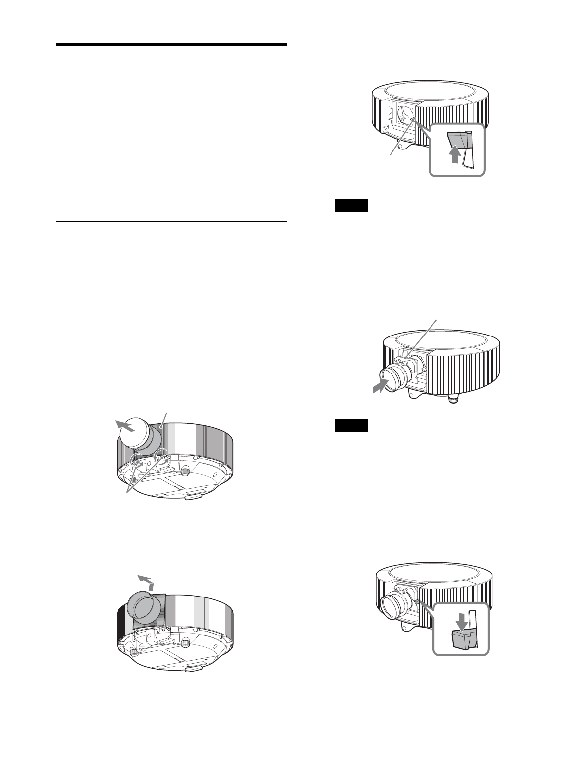
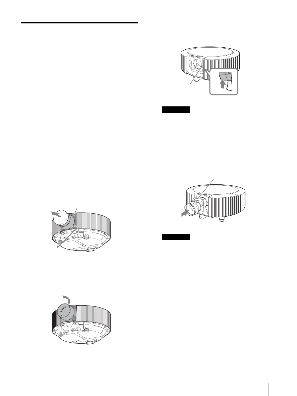
2
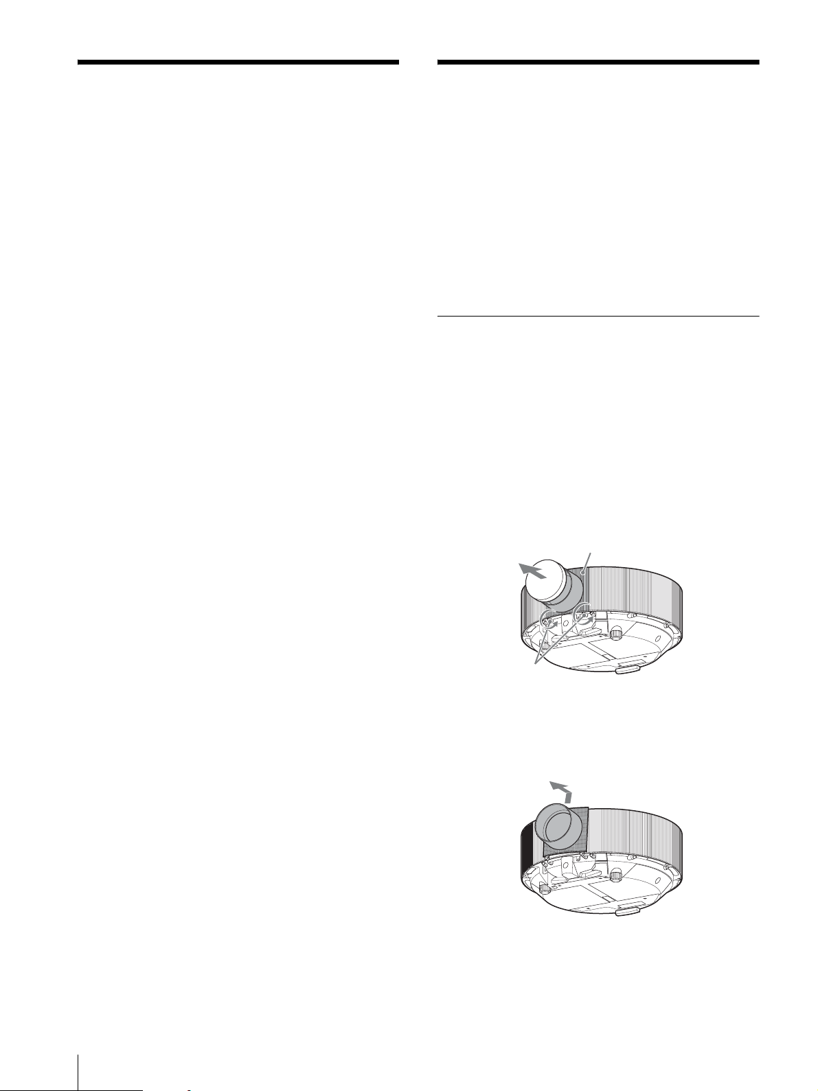
レンズカバーをはずす。
1 レンズカバーのレンズホールカバーをはずす。
2 下部のネジ 2 本をゆるめる。
レンズカバー
1
概要/レンズの取り付けかた
8
2
3 レンズカバーを少し上に持ち上げながら手前に引
いてはずす。( レンズカバーは上面の 2 か所のツ
メで固定されています。)
3
3
レンズ固定レバーを上に持ち上げ、ロックをはずす。
レンズ固定レバー
ご注意
レンズ固定レバーは確実に上に持ち上げてください。
レバーが確実に上がっていないとレンズを取り付け
たり、外したりできません。
6
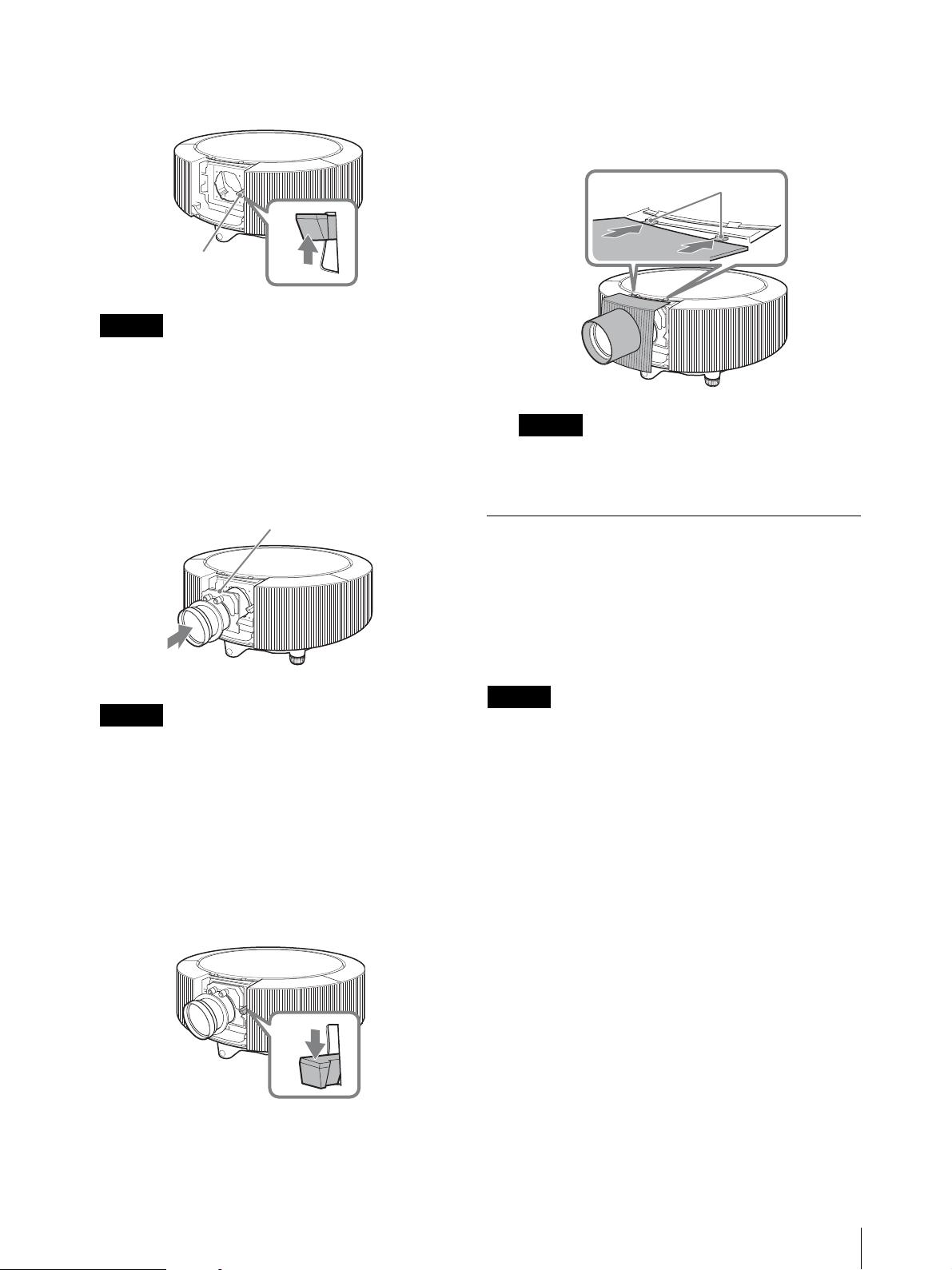
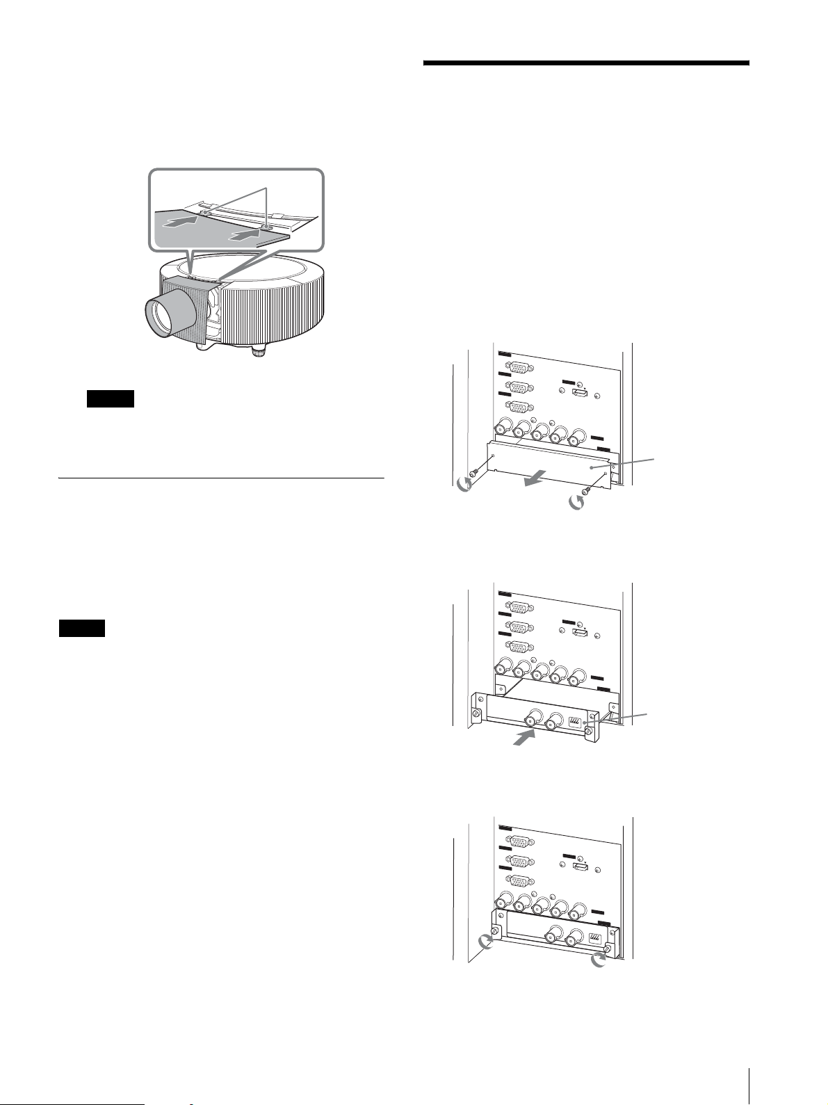
レンズカバーを元どおり取り付ける。
2 か所のツメを合わせてから、レンズカバーをレンズ
にかぶせ、下部のネジ 2 本を締めます。
ツメ
4
レンズからレンズキャップ(2 個)をはずし、白丸
マークを上にして奥までまっすぐ差し込む。
白丸マーク
ご注意
・ レンズの取り付けの際は、レンズのガラス面がレ
バーなどにあたらないよう、慎重に行ってくださ
い。
・ レンズが奥まで入らない場合は、レンズを少し左
右に回しながら入れてください。
5
レンズ固定レバーを下まで確実に下げる。
ご注意
レンズ固定レバーが完全に下がっていないとレンズ
カバーを固定できません。
レンズを交換する
レンズ交換のしかたは、前述の「レンズを取り付ける」
の手順と同じです。手順
バーのロックをはずした後、レンズを持ってまっすぐ前
に引き出します。その後、手順 4 〜 6 を行い、別のレン
ズを取り付けます。
ご注意
レンズを取り出す際は、両手を添えて取り出してくださ
い。
1 〜 3 を行ってレンズ固定レ
レンズがロックされます。
レンズ固定レバーが下がらない場合は、レンズが奥
まで入っていない可能性があります。レンズを入れ
直し、レバーを下まで確実に下げてください。
レンズの取り付けかた
9
HD-SDI/SDI 入力アダプター BKM-
HD-SDI/SDI 入力アダ
プターの取り付けかた
別売の HD-SDI/SDI 入力アダプター BKM-FW16 をプロ
ジェクターのコネクターパネル部の INPUTE に取り付け
ることができます。
1
プロジェクターの電源を切り、電源コードをコンセ
ントから抜く。
2
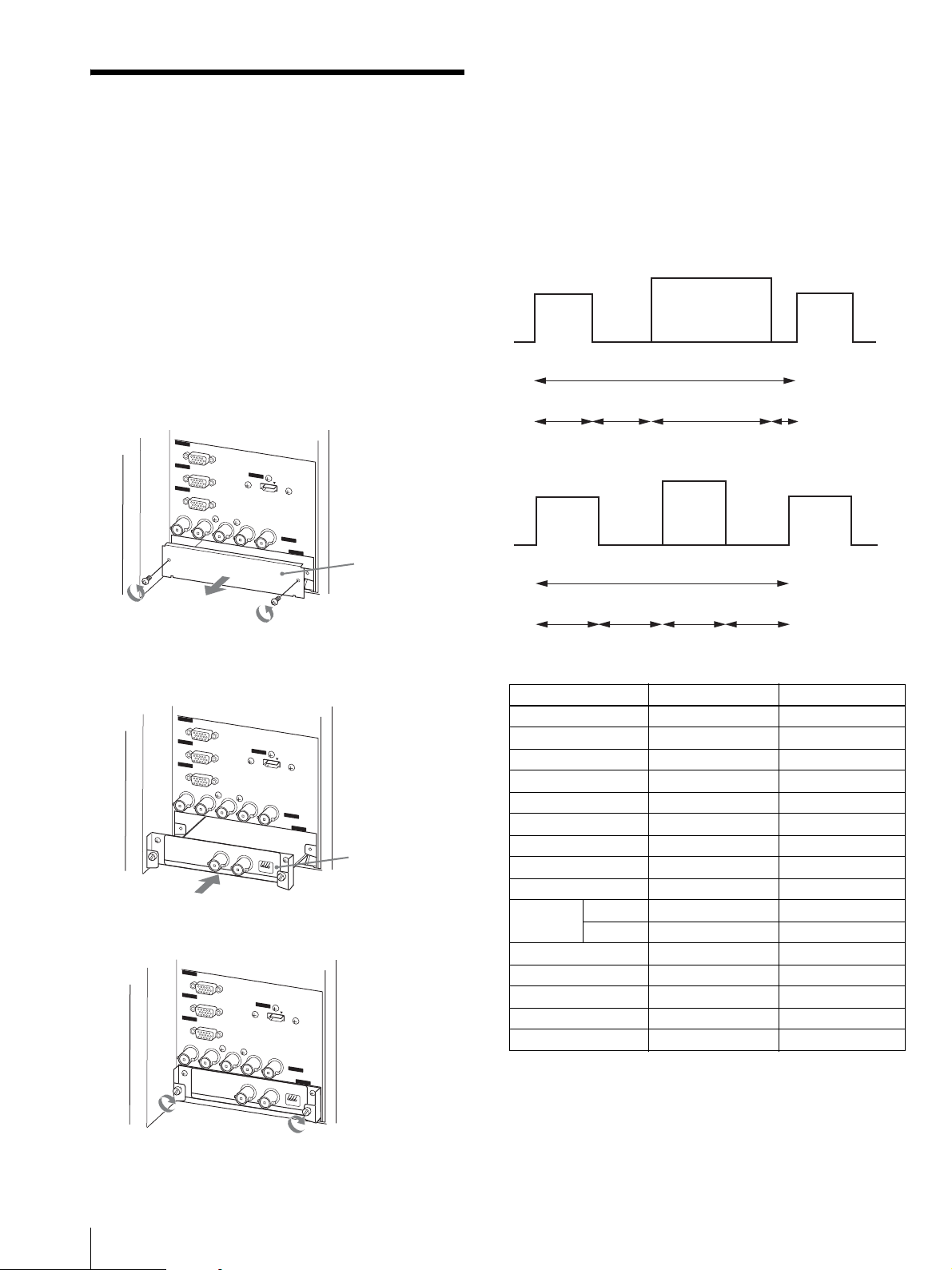
コネクターパネルに取り付けてあるブランクパネル
の固定ネジ(2 本)を外し、ブランクパネルを取りは
ずす。
INPUT A
RGB
INPUT B
RGB
OUTPUT
MONITOR
R/R-Y/P
R
3
HD-SDI/SDI 入力アダプター BKM-FW16 を奥まで差
し込む。
INPUT A
RGB
INPUT B
RGB
OUTPUT
MONITOR
R/R-Y/P
R
HDSDI/SDI
4
ネジ(2 か所)を締めて BKM-FW16 を固定する。
INPUT A
INPUT B
OUTPUT
MONITOR
R/R-Y/P
R
G/Y
B/B-Y/P
G/Y
B/B-Y/P
HDSDI/SDI
INPUT ADAPTOR
RGB
RGB
G/Y
B/B-Y/P
HDSDI/SDI INPUT ADAPTOR
INPUT D
HDMI
B
HD
VD
INPUT C
INPUT E
ブランクパネル
INPUT D
HDMI
B
HD
VD
INPUT C
INPUT E
AUDIO
CHANNEL
HD-SDI/SDI
入力アダプター
BKM-FW16
INPUT D
HDMI
B
HD
VD
INPUT C
INPUT E
HDSDI/SDI
AUDIO
CHANNEL
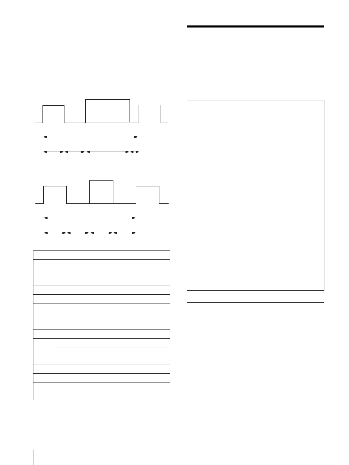
FW16 使用時のご注意
2K×1K(2048×1080)信号を入力した場合、両端縦 1
ラインの情報が表示されません。また、ネイティブな表
示とはなりません。2K×1K 相当。
2K×1K 信号の仕様
水平
アクティブビデオ
水平
同期幅
A+B+C+D
水平同期幅
A
バックポーチ
B
アクティブビデオ
C
フロントポーチ
垂直
アクティブ
垂直
ビデオ
同期幅
E+F+G+H
F
アクティブ
ビデオ
G
フロントポーチ
H
垂直同期幅
E
バックポーチ
信号 2K×1K/24p 2K×1K/24PsF
解像度 2048 × 1080 2048 × 1080
フレームレート(Hz) 24 48
ドットクロック (MHz) 74.25 74.25
A4444
B6464
C 2048 2048
D 594 594
A + B + C + D 2750 2750
fH(kHz) 27 27
同期両極性 水平同期 n n
垂直同期 n n
E55
F3636
G 1080 1080
H44
E + F + G + H 1125 1125
水平
同期幅
D
垂直
同期幅
10
HD-SDI/SDI 入力アダプターの取り付けかた
設置寸法
ここでは、プロジェクターの設置場所と使用レンズ、投
影画面サイズに応じた設置寸法を記載します。
◆それぞれの設置図と設置寸法表は、59 〜 75 ページをご
覧ください。
天井つり(63 ページ CD)
プロジェクターを天井からつり下げて設置する場合の設
置例を示します。
天井つりの場合は、プロジェクターサスペンションサ
ポート PSS-630(別売)をご使用ください。
設置は、代理店またはソニーサービスにおまかせくださ
い。
設置図と設置寸法表の記号について
59 〜 75 ページのイラスト、表および計算式のアルファ
ベットは以下の意味を示します。
SS: スクリーンサイズ対角(インチ)
a : レンズの中心からスクリーンまでの距離
a’ : 天吊り金具取り付け穴(レンズ側)からスクリーン
までの距離
b、b’ : 床または天井からレンズの中心までの距離
c、c’ : 床置きの場合:床からプロジェクターの脚までの
距離
天井つりの場合:天井からプロジェクターサスペン
ションサポートの取り付け面までの距離
d : 左右調整範囲
x : 床または天井からスクリーンの中心までの距離(任
意)
N :最小値
M : 最大値
単位
59 〜 75 ページのイラストおよび表の数値の単位は、
「mm(インチ)」です。
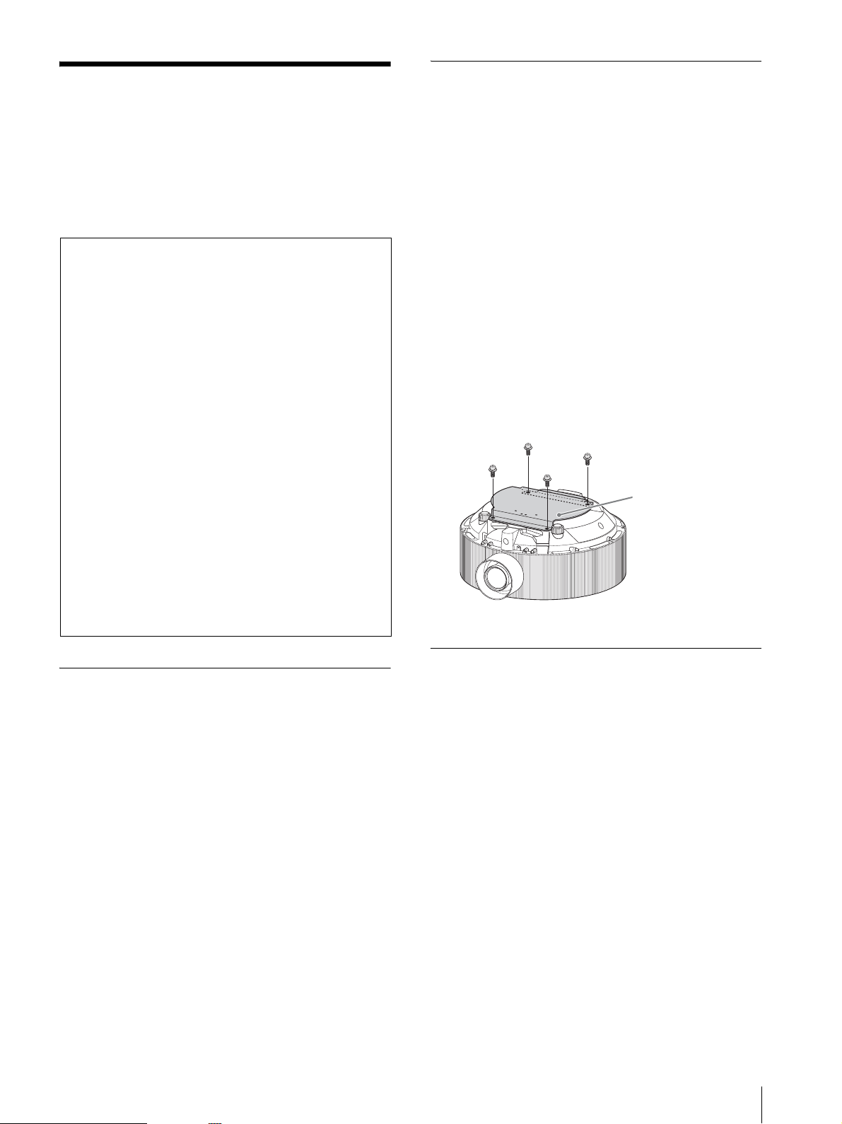
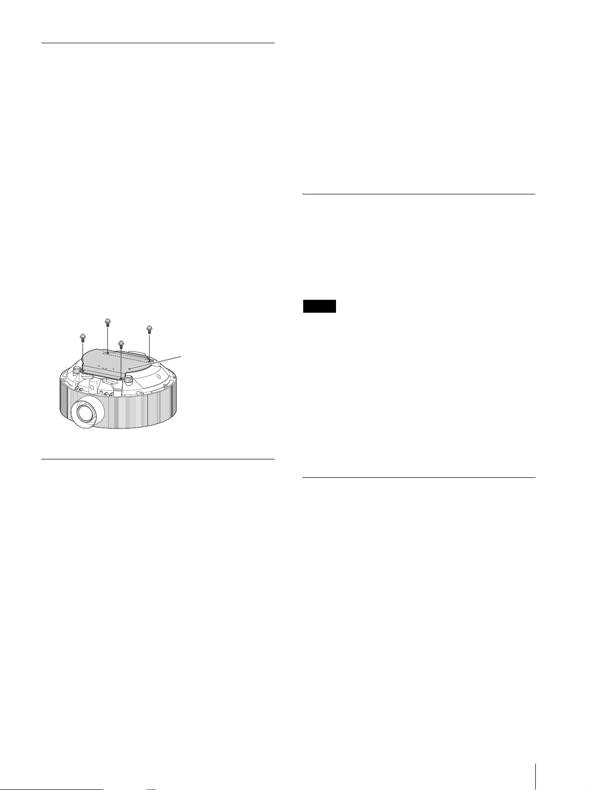
ダストカバー取り付けのご注意
天井つりの場合は、必ず付属のダストカバーを取り付け
てください。
天吊り金具取り付け穴を利用し、PSS-630 のプロジェク
ター用マウントブラケットと共にダストカバーをプロ
ジェクターに固定します。
固定用のネジは、PSS-630 に付属のネジ、または埋め込み
の深さが 10 〜 11mm の M6 ネジ ( 市販 ) をご使用くださ
い。
ダストカバー(付属)
床置き(59 ページ AB)
プロジェクターを机などの上に置いて設置する場合の設
置例を示します。
短焦点固定レンズ VPLL-4008 使用時の
ご注意
VPLL-4008 はリア投影(打ち込み角 0°)用であり、水
平・垂直方向ともにスクリーンの中心とレンズの中心が
同じになるように設置する必要があります。中心からず
れた状態で設置すると、画が欠けますのでご注意くださ
い。
また、設置後は設置設定メニューのレンズコントロール
を「切」に設定することをおすすめします。
プロジェクターサスペンションサ
ポート PSS-630 の取り付けかた
(67 ページ EFG)
ここでは、プロジェクターサスペンションサポート PSS630 を使って、標準ズームレンズ VPLL-Z4019 付きの本機
を天井に取り付けた場合の寸法について説明します。
◆天井への設置に関して詳しくは、PSS-630 の取付説明書
をご覧ください。
プロジェクターの高さ調節
天井からプロジェクターサスペンションサポートの取り
付け面までの距離(図 F の c 値)は、別売のプロジェク
ターサスペンションサポートジョイントポール PSS-630P
を使用すると、次の範囲で調節可能です。
PSS-630P 未使用時:350/380/410/440/470/500mm
PSS-630P を 1 本使用時:630/660/690/720/750/780mm
PSS-630P を 2 本使用時:910/940/970/1,000/1,030/1,060
mm
設置寸法
11

PSS-630P を 3 本使用時:1,190/1,220/1,250/1,280/1,310/
1,340mm
床置き、ツインスタック
(68 ページH)
プロジェクターを机などの上でツインスタックにして設
置する場合の設置例を示します。
80 インチから 600 インチのスクリーンがご使用になれま
す。
ご注意
安全にお使いになるため、またメンテナンスのために、
設置する際は壁からの距離を左右後方各 50cm 以上離し
て設置してください。
スタックをする際のご注意
1
スタックの設置例 H の a値に従ってプロジェクター
を設置する。
2
ズームを使って上下のプロジェクターからの画像が
スクリーンいっぱいに映るように画像サイズを調整
する。
プロジェクターの外形寸法
(72 〜 75 ページ I 〜 N)
プロジェクターの外形寸法については、「寸法図」(72 〜
75 ページ)をご覧ください。標準ズームレンズ VPLLZ4019 を取り付けた場合の寸法図を記載します。
前面 I
天面 J
側面 K
底面 L
後面 M
天吊金具取付寸法 N
12
設置寸法

English
Table of Contents
Precautions ...........................................................14
Overview ...............................................................15
Attaching a Lens ..................................................16
Attaching a Lens ...............................................16
Replacing the Lens ...........................................17
Installing the HD-SDI/SDI Input Adaptor ........ 17
Installation Diagram ...........................................18
Floor Installation ............................................... 18
Ceiling Installation ...........................................19
Attaching the PSS-630 Projector Suspension
Support ............................................................19
Floor Installation for Twin Stacking ................. 19
Projector Dimensions........................................ 19
Installation Diagram ...........................................59
Floor Installation .............................................. 59
Ceiling Installation ...........................................63
Attaching the PSS-630 ..................................... 67
Twin Stacking ...................................................68
Dimensions ...........................................................72
Table of Contents
13

Precautions
On safety
• Check that the operating voltage of your unit is
identical with the voltage of your local power supply.
If voltage adaptation is required, consult with
qualified Sony personnel.
• Should any liquid or solid object fall into the cabinet,
unplug the unit and have it checked by qualified Sony
personnel before operating it further.
• Unplug the unit from the wall outlet if it is not to be
used for several days.
• To disconnect the cord, pull it out by the plug. Never
pull the cord itself.
• The wall outlet should be near the unit and easily
accessible.
• The unit is not disconnected from the AC power
source (mains) as long as it is connected to the wall
outlet, even if the unit itself has been turned off.
• Do not look into the lens while the lamp is on.
• Do not place your hand or objects near the ventilation
holes – the air coming out is hot.
• Avoid using an extension cord with a low voltage
limited since it may cause the short-circuit and
physical incidents.
• Do not catch your finger between the unit and surface
of the floor when moving the projector installed on the
floor.
• Be careful not to catch your finger in the cooling fan.
• Do not carry the projector with the cabinet on and with
its cover open.
• Be sure to use two peoples to grasp both sides of the
unit when carrying the unit.
On installation
• When the projector is mounted on the ceiling, the
Sony PSS-630 Projector Suspension Support must be
used for installation.
• Be sure to install the supplied dust cover when
mounting the projector on the ceiling.
• Allow adequate air circulation to prevent internal heat
build-up. Do not place the unit on surfaces (rugs,
blankets, etc.) or near materials (curtains, draperies)
that may block the ventilation holes.
Leave space of more than 30 cm (11
between the wall and the projector. Be aware that
room heat rises to the ceiling; check that the
temperature near the installation location is not
excessive.
• Install the projector on the floor or ceiling. Any other
installation causes a malfunction such as color
irregularity or shortening lamp life.
• Do not install the unit in a location near heat sources
such as radiators or air ducts, or in a place subject to
7
/8 inches)
direct sunlight, excessive dust or humidity,
mechanical vibration or shock.
• To avoid moisture condensation, do not install the unit
in a location where the temperature may rise rapidly.
• Be sure to secure the cabinet cover firmly when
installing to the ceiling firmly.
Warning
For customers who purchase this unit
If customers perform the installation described in this
manual, an accident may occur, causing serious injury.
Never install it by yourself. For installation, be sure to
consult with qualified Sony personnel.
For dealers
Please read this Installation Manual thoroughly for safe
installation.
On illumination
• To obtain the best picture, the front of the screen
should not be exposed to direct lighting or sunlight.
• Ceiling-mounted spot lighting is recommended. Use a
cover over fluorescent lamps to avoid lowering the
contrast ratio.
• Cover any windows that face the screen with opaque
draperies.
• It is desirable to install the projector in a room where
floor and walls are not of light-reflecting material. If
the floor and walls are of reflecting material, it is
recommended that the carpet and wall paper be
changed to a dark color.
On preventing internal heat build-up
• After you turn off the power with the @ / 1 key on the
control panel or on the Remote Commander, do not
disconnect the unit from the wall outlet while the
cooling fan is still running.
• Do not disconnect the AC power cord from the wall
outlet while the fan is still running.
Caution
The projector is equipped with ventilation holes (intake
and exhaust). Do not block or place anything near these
holes, or internal heat build-up may occur, causing
picture degradation or damage to the projector.
On cleaning
Before cleaning
Be sure to disconnect the AC power cord from the AC
outlet.
On replacing the air filters
When the air filter replacement message appears,
replace both air filters with new ones.
For the air filter replacement, refer to “Replacing the
Air Filters” in the supplied Operating Instructions.
14
Precautions

On cleaning the lens
The lens surface is especially treated to reduce reflection
of light.
As incorrect maintenance may impair the performance
of the projector, take care with respect to the following:
• Avoid touching the lens. To remove dust on the lens,
use a soft dry cloth. Do not use a damp cloth, detergent
solution, or thinner.
• Wipe the lens gently with a soft cloth such as a
cleaning cloth or glass cleaning cloth.
• Stubborn stains may be removed with a soft cloth such
as a cleaning cloth or glass cleaning cloth lightly
dampened with water.
• Never use solvent such as alcohol, benzene or thinner,
or acid, alkaline or abrasive detergent, or chemical
cleaning cloth, as they will damage the lens surface.
On cleaning the cabinet
• Clean the cabinet gently with a soft dry cloth.
Stubborn stains may be removed with a cloth lightly
dampened with mild detergent solution, followed by
wiping with a soft dry cloth.
• Use of alcohol, benzene, thinner or insecticide may
damage the finish of the cabinet or remove the
indications on the cabinet. Do not use these chemicals.
• If you rub on the cabinet with a stained cloth, the
cabinet may be scratched.
• If the cabinet is in contact with a rubber or vinyl resin
product for a long period of time, the finish of the
cabinet may deteriorate or the coating may come off.
Overview
This manual describes how to install the Sony VPLFH300L/FW300L Data Projector, how to attach a lens to
the projector, and installation diagrams.
On repacking
Save the original shipping carton and packing material;
they will come in handy if you ever have to ship your
unit. For maximum protection, repack your unit as it was
originally packed at the factory.
Overview
15
Attaching a Lens
The projector comes from the factory with no lens
attached. You can attach the following types of optional
lenses to the projector:
• VPLL-Z4019 Standard Zoom Lens
• VPLL-4008 Fixed Short Focus Lens (for rear
projection, optical axis angle 0 degrees))
• VPLL-Z4015 Short Focus Zoom Lens
• VPLL-Z4025 Middle Focus Zoom Lens
• VPLL-Z4045 Long Focus Zoom Lens
Attaching a Lens
3
Move the lens fixing lever upward to unlock.
Lens fixing lever
Note
Move the lens fixing lever completely upward.
Otherwise you cannot attach or remove the lens.
Follow the steps below to attach a lens:
For details on the lens, also refer to the operating
instructions supplied with the lens.
1
Turn off the power of the projector and disconnect
the power cable.
2
Remove the lens cover.
1 Remove the lens hole cover.
2 Loosen the two screws at the bottom.
1
2
3 While lifting the lens cover, pull it toward you
to remove. (The lens cover is fixed to the
projector with two tabs on the top.)
Lens cover
4
Remove two lens caps and insert the lens straight
with a white circle mark up, as far as it goes.
White circle mark
Notes
• Attach the lens carefully so as not to damage the
lens glass with the lever or other parts.
• If the lens does not go in fully, turn the lens
slightly right and left.
5
Move the lens fixing lever down to the bottom
correctly.
The lens is locked.
16
3
If the lens fixing lever does not move down, the lens
may not be fully inserted. Insert it again and move
the lens fixing lever down to the bottom correctly.
Attaching a Lens
6
Replace the lens cover.
Align the two tabs with the slots, place the lens
cover over the lens, then tighten the two screws at
the bottom.
Tabs
Note
Move the lens fixing lever completely downward.
Otherwise you cannot lock the lens.
Installing the HD-SDI/SDI
Input Adaptor
You can install the optional BKM-FW16 HD-SDI/SDI
Input Adaptor in INPUT E of the connector panel
section of the projector.
1
Turn off the power of the projector and disconnect
the power cable.
2
Remove the two screws from the blank panel
attached to the connector panel section, and remove
the blank panel.
INPUT A
RGB
INPUT B
OUTPUT
R/R-Y/P
RGB
MONITOR
R
INPUT D
HDMI
G/Y
B/B-Y/P
B
HD
VD
INPUT C
INPUT E
Blank panel
Replacing the Lens
The procedure for replacing the lens is the same as that
for “Attaching a Lens.” Perform steps 1 to 3 to unlock
the lens fixing lever, and withdraw the lens straight
forward. Then perform steps 4 to 6 to attach another
lens.
Note
Use both hands to withdraw the lens.
3
Insert the BKM-FW16 HD-SDI/SDI Input Adaptor
as far as it goes.
INPUT A
RGB
INPUT B
RGB
OUTPUT
MONITOR
R/R-Y/P
R
HDSDI/SDI
4
Tighten the two screws on the BKM-FW16.
INPUT A
RGB
INPUT B
RGB
OUTPUT
MONITOR
R/R-Y/P
R
G/Y
B/B-Y/P
B
HDSDI/SDI
INPUT ADAPTOR
G/Y
B/B-Y/P
B
HDSDI/SDI INPUT ADAPTOR
INPUT D
HD
INPUT D
HD
HDSDI/SDI
AUDIO
CHANNEL
HDMI
VD
INPUT C
INPUT E
BKM-FW16
HD-SDI/
SDI Input
Adaptor
HDMI
VD
INPUT C
INPUT E
AUDIO
CHANNEL
Installing the HD-SDI/SDI Input Adaptor
17
Note on BKM-FW16 HD-SDI/SDI Input
Adaptor
When a 2K × 1K (2048 × 1080) signal is input,
information of a vertical line at both ends is not
displayed. The signal being displayed is not native. 2K
× 1K equivalent.
Specifications of 2K × 1K signal
Horizontal timing
Installation Diagram
This section gives projector installation examples
according to the installation location, lens and display
size.
For the installation diagrams and dimension tables, see
pages 59 to 75.
Horizontal
sync width
Horizontal
sync width
A
A + B + C + D
Back
porch
B
Active video
Active video
C
Horizontal
sync width
Front
porch
D
Alphabetical letters in the diagrams and
tables
Alphabetical letters are shown in the illustrations,
tables and calculation methods on pages 59 to 75.
These letters indicate the following:
SS : screen size measured diagonally (inches)
a : distance between the screen and the center of
the lens
a': distance between the screen and the screw hole
Vertical timing
(on the lens side) for the ceiling bracket
b, b': distance between the floor/ceiling and the
Ver tica l
sync width
Active
video
Ver tic al
sync width
center of the lens
c, c': distance between the floor and the bottom of
the adjusters of the projector for the floor
installation, or distance between the ceiling
and the surface of the Projector Suspension
Support for the ceiling installation
d : adjustment range of left or right side
x : distance between the floor/ceiling and the
center of the screen, free
Ver ti ca l
sync width
E
E + F + G + H
Back
porch
F
Active
video
G
Front
porch
H
N : minimum
Signal 2K × 1K/24p 2K × 1K/24PsF
Resolution 2048 × 1080 2048 × 1080
Frame rate (Hz) 24 48
Dot clock (MHz) 74.25 74.25
A4444
B6464
C20482048
D 594 594
A+B+C+D 2750 2750
fH (kHz) 27 27
Sync
polarity
E55
F3636
G10801080
H44
E+F+G+H 1125 1125
Horizontal sync n n
Vertical sync n n
M : maximum
Unit of dimensions
The unit of dimensions shown in the illustrations and
tables on pages 59 to 75 is “mm (inches).”
Floor Installation (A and B on
page 59)
This section gives examples for installing the projector
on the desk, etc.
Note on VPLL-4008 Fixed Short Focus
Lens
The VPLL-4008 is the lens for rear projection (optical
axis angle: 0 degrees). When using the VPLL-4008, you
should install the projector with the center of the lens
aligned with the center of the screen in the horizontal/
vertical direction. Otherwise, a portion of the picture
may be invisible.
Also, after installing the lens, we recommend setting
“Lens Control” in the Installation menu to “Off.”
18
Installation Diagram
Ceiling Installation (C and D on
page 63)
This section gives examples for installing the projector
on the ceiling.
When installing the projector on the ceiling, use the
optional PSS-630 Projector Suspension Support.
For ceiling installation, consult with qualified Sony
personnel only.
Note on the dust cover
When installing the projector on the ceiling, be sure to
attach the supplied dust cover to the projector.
Fix the dust cover to the ceiling bracket mounting holes
of the projector together with the projector mounting
bracket of the PSS-630.
The mounting screws are not supplied. Use the screws
supplied with the PSS-630 or commercially available
M6 screws with embedment length of 10 to 11 mm
13
(
/32 to 7/16 inches).
Dust cover (supplied)
Without using PSS-630P poles: 350/380/410/440/470/
500 mm (13
inches)
Using one PSS-630P pole: 630/660/690/720/750/780
mm (24
Using two PSS-630P poles: 910/940/970/1,000/1,030/
1,060 mm (35
3
41
/4 inches)
Using three PSS-630P poles: 1,190/1,220/1,250/1,280/
1,310/1,340 mm (47 / 48
7
52
/8 inches)
7
/8 / 15 / 16 1/4 / 17 3/8 / 18 5/8 /19 3/4
7
/8 / 26 / 27 1/4 / 28 3/8 / 29 5/8 / 30 3/4 inches)
7
/8 / 37 1/8 / 38 1/4 / 39 3/8 / 40 5/8 /
1
/8 / 49 1/4 / 50 1/2 / 51 5/8 /
Floor Installation for Twin Stacking
(H on page 68)
This section gives examples for installing two projectors
on the desk using twin-stacking.
80 to 600-inch screens are available for twin stack
installation.
Note
For safety and maintenance purposes, install the
projectors away from the wall. Leave a minimum space
of 50 cm (19
3
/4 inches) from both sides and the rear.
Attaching the PSS-630 Projector
Suspension Support (E, F and G
on page 67)
The installation measurements are shown when you
install the projector with the VPLL-Z4019 Standard
Zoom Lens on the ceiling using the PSS-630 Projection
Suspension Support.
For more details on the ceiling installation, refer to the
Installation manual for Dealers of the PSS-630.
Adjusting the Projector Height
The distance between the ceiling and the mounting
surface of the Projector Suspension Support (value “c”
in Fig. F) is adjustable in the following range. The
optional PSS-630P Projector Suspension Support Joint
Pole is available for the height adjustment.
Note on stacking
1
Install the projector following the “a” value in
stacking example H.
2
Use the zoom to align the pictures from the first and
second projectors so that they fill the screen.
Projector Dimensions (I to N on
pages 72 to 75)
This section gives the projector outside dimensions with
the VPLL-Z4019 Standard Zoom Lens.
For the dimension drawings, see pages 72 to 75.
Front I
Top J
Side K
Bottom L
Rear M
Ceiling bracket dimensions N
Installation Diagram
19

Français
Table des matières
Précautions ........................................................... 21
Aperçu .................................................................. 22
Montage d’un objectif ......................................... 23
Montage d’un objectif ...................................... 23
Remplacement de l’objectif ............................. 24
Installation de l’adaptateur d’entrée
HD-SDI/SDI ......................................................... 24
Schéma d’installation .......................................... 25
Installation au sol ............................................. 25
Installation au plafond ...................................... 26
Installation du support de suspension pour
projecteur PSS-630 ........................................ 26
Installation au sol pour double empilage ......... 26
Dimensions du projecteur ................................ 27
Schéma d’installation .......................................... 59
Installation su sol ............................................. 59
Installation au plafond ...................................... 63
Fixation du PSS-630 ........................................ 67
Double empilage .............................................. 68
Dimensions ........................................................... 72
20
Table des matières

Précautions
Sécurité
• Assurez-vous que la tension de service de votre
projecteur est identique à la tension locale. Si un
adaptateur de tension est nécessaire, informez-vous
auprès d’un technicien Sony agréé.
• Si du liquide ou un objet solide pénètre dans le coffret,
débranchez l’appareil et faites-le vérifier par un
technicien Sony agréé avant de poursuivre
l’utilisation.
• Débranchez le projecteur de la prise murale en cas de
non-utilisation pendant plusieurs jours.
• Pour débrancher le cordon, tirez-le par la fiche. Ne
tirez jamais sur le cordon lui-même.
• La prise murale doit se trouver à proximité du
projecteur et être facile d’accès.
• L’appareil demeure connecté à la source
d’alimentation secteur (principale) tant qu’il est
branché sur la prise murale, et ce même si l’appareil
est éteint.
• Ne regardez pas dans l’objectif lorsque la lampe est
allumée.
• Ne mettez pas la main et ne posez aucun objet près des
orifices de ventilation ; l’air qui s’en échappe est très
chaud.
• Evitez d’utiliser une rallonge avec une basse tension
limitée car elle risque de provoquer des courts circuits
et des incidents physiques.
• Ne vous coincez pas les doigts entre l’appareil et la
surface du plancher lorsque vous déplacez le
projecteur installé au sol.
• Ne vous coincez pas les doigts dans le ventilateur.
• Ne transportez pas le projecteur avec son boîtier et son
couvercle ouvert.
• Deux personnes doivent transporter l’appareil en le
saisissant par les deux côtés.
Installation
• Lorsque le projecteur est monté au plafond, vous
devez utiliser le support de suspension pour projecteur
Sony PSS-630 pour l’installation.
• Installez le couvercle anti-poussière fourni lors de
l’installation du projecteur au plafond.
• Assurez une circulation d’air adéquate afin d’éviter
toute surchauffe interne. Ne placez pas le projecteur
sur des surfaces textiles (tapis, couvertures, etc.) ni à
proximité de rideaux ou de draperies susceptibles
d’obstruer les orifices de ventilation.
Laissez un dégagement de plus de 30 cm (11
pouces) entre le mur et le projecteur. La chaleur de la
pièce monte au plafond ; vérifiez que la température
près de l’emplacement d’installation n’est pas
excessive.
7
/8
• Installez le projecteur au sol ou au plafond. Toute autre
installation provoque un dysfonctionnement tel
qu’une irrégularité des couleurs ou une diminution de
la durée de vie de la lampe.
• Ne placez pas l’appareil à proximité de sources de
chaleur comme des radiateurs ou des conduits d’air ou
dans des endroits exposés au rayonnement direct du
soleil, à des poussières excessives ou à l’humidité, à
des vibrations mécaniques ou à des chocs.
• Pour éviter la condensation d’humidité, n’installez pas
le projecteur dans un endroit où la température est
susceptible d’augmenter rapidement.
• Assurez-vous que le couvercle du boîtier est fixé
correctement lorsque vous l’installez au plafond.
Avertissement
Pour les clients qui achètent cet appareil
Il y a risque d’accident et de grave blessure si le client
tente d’effectuer lui-même l’installation décrite dans ce
manuel. Vous ne devez pas effectuer l’installation
vous-même. Pour l’installation, informez-vous auprès
d’un technicien Sony qualifié.
Pour les revendeurs
Veuillez lire attentivement ce Manuel d’installation pour
une installation sûre.
Eclairage
• Pour une qualité d’image optimale, la face avant de
l’écran ne doit pas être directement exposée à une
source d’éclairage ou au rayonnement solaire.
• Nous préconisons un éclairage au moyen de spots
fixés au plafond. Masquez les lampes fluorescentes
pour éviter une altération du niveau de contraste.
• Occultez les fenêtres qui font face à l’écran au moyen
de rideaux opaques.
• Il est préférable d’installer le projecteur dans une
pièce où le sol et les murs ne sont pas revêtus d’un
matériau réfléchissant la lumière. Si le sol et les murs
réfléchissent la lumière, nous vous recommandons de
remplacer le revêtement de sol et mural par un de
couleur sombre.
Prévenir l’accumulation de chaleur
interne
• Après avoir mis l’appareil hors tension à l’aide de la
touche @ / 1 du panneau de commande ou de la
télécommande, ne débranchez pas l’appareil de la
prise murale alors que le ventilateur de
refroidissement tourne encore.
• Ne débranchez pas le cordon d’alimentation de la
prise murale alors que le ventilateur tourne encore.
Attention
Le projecteur est équipé d’orifices de ventilation (prise
d’air et sortie d’air). N’obstruez pas ces orifices et ne
placez rien à proximité car vous risqueriez de provoquer
Précautions
21

une surchauffe interne pouvant entraîner une altération
de l’image ou des dommages au projecteur.
Nettoyage
Avant le nettoyage
Veillez à débrancher le cordon d’alimentation de la prise
de courant alternatif.
Remplacement des filtres à air
Lorsque le message de remplacement des filtres à air
apparaît, remplacez les deux filtres à air.
Pour plus de détails sur le remplacement des filtres à air,
reportez-vous à la section « Remplacement des filtres à
air » dans le Mode d’emploi fourni.
Nettoyage de l’objectif
La surface de l’objectif a été soumise à un traitement
spécial, destiné à réduire la réflexion de la lumière.
Un entretien incorrect peut réduire les performances du
projecteur. Veillez à ce qui suit :
• Ne touchez pas l’objectif. Pour dépoussiérer
l’objectif, employez un chiffon doux et sec. N’utilisez
pas de chiffon humide, de solution détergente ni de
diluant.
• Passez un chiffon doux (chiffon de nettoyage ou pour
vitres) sur l’objectif, sans frotter.
• Eliminez les taches tenaces avec un chiffon doux
(chiffon de nettoyage ou pour vitres) légèrement
imprégné d’eau.
• N’utilisez jamais de solvants tels que l’alcool, le
benzène, les diluants ou les détergents acides, alcalins
ou abrasifs, ni un chiffon de nettoyage chimique, car
ils risqueraient d’endommager la surface de l’objectif.
Aperçu
Ce manuel décrit comment installer le vidéoprojecteur
Sony VPL-FH300L/FW300L, comment fixer un
objectif sur le projecteur et fournit des schémas
d’installation.
Nettoyage du boîtier
• Nettoyez le boîtier avec un chiffon doux et sec sans
frotter. Eliminez les taches tenaces avec un chiffon
légèrement imprégné d’une solution détergente
neutre, puis essuyez avec un chiffon doux sec.
• L’utilisation d’alcool, de benzène, de diluants ou
d’insecticide risque d’endommager la finition du
boîtier ou d’effacer les instructions indiquées sur ce
dernier. N’utilisez pas ce type de produits chimiques.
• Si vous frottez le boîtier avec un chiffon sale, vous
risquez de le griffer.
• En cas de contact prolongé du boîtier avec du
caoutchouc ou de la résine vinylique, la finition risque
de se détériorer ou le revêtement de se décoller.
Remballage
Conservez le carton d’emballage original et le matériel
d’emballage ; ils seront très utiles si vous devez un jour
expédier l’appareil. Pour assurer une protection
maximale, remballez l’appareil tel qu’il avait été
emballé en usine.
22
Aperçu
Montage d’un objectif
Le projecteur est fourni sans objectif. Vous pouvez
monter les types d’objectifs en option suivants sur le
projecteur :
• Zoom standard VPLL-Z4019
• Objectif à courte focale fixe VPLL-4008 (pour
projection arrière, angle d’axe optique 0 degré)
• Objectif à courte focale VPLL-Z4015
• Objectif à focale moyenne VPLL-Z4025
• Objectif à longue focale VPLL-Z4045
Montage d’un objectif
Suivez les étapes ci-dessous pour monter un objectif :
Pour plus de détails sur l’objectif, reportez-vous
également au mode d’emploi fourni avec ce dernier.
1
Mettez le projecteur hors tension et débranchez le
câble d’alimentation.
3
Déplacez le levier de fixation d’objectif vers le haut
pour le déverrouiller.
Levier de fixation d’objectif
Remarque
Déplacez le levier de fixation d’objectif totalement
vers le haut. Autrement, vous ne pouvez pas monter
ou retirer l’objectif.
4
Retirez les deux capuchons d’objectif et insérez
l’objectif repéré par un cercle blanc vers le haut,
aussi loin que possible.
2
Retirez le couvercle de l’objectif.
1 Retirez le cache d’orifice d’objectif.
2 Desserrez les deux vis situées sur le dessous.
1
2
3 Tout en soulevant le couvercle de l’objectif,
tirez-le vers vous pour l’enlever. (Le couvercle
de l’objectif est fixé au projecteur à l’aide de
deux languettes en haut.)
Couvercle de l’objectif
3
Cercle blanc
Remarques
• Lorsque vous montez l’objectif, prenez soin de ne
pas endommager le verre de l’objectif avec le
levier ou d’autres pièces.
• Si vous ne parvenez pas à insérer l’objectif
entièrement, tournez-le légèrement vers la droite
et la gauche.
Montage d’un objectif
23
 Loading...