

Page 1

Data
Projector
4-593-103-11 (2)
Operating Instructions
Before operating the unit, please read this manual and supplied Quick Reference Manual
thoroughly and retain it for future reference.
VPL-DX270/DX240/DX220
VPL-DW240
Not all models are available in all countries and area. Please check
with your local Sony Authorized Dealer.
© 2016 Sony Corporation
Page 2

Table of Contents
Overview
Location and Function of Controls .... 3
Main Unit .....................................3
Terminal Panel ..............................4
Remote Commander and Control
Panel Keys .................................5
Preparation
Connecting the Projector ................... 7
Connecting a Computer ................7
Connecting a Video equipment .... 8
Connecting to an external
device ........................................9
Supplying the power to the external
device ........................................9
Projecting an Image
Projecting an Image ......................... 10
Adjusting the Projected image ... 11
Turning Off the Power ................15
Others
Indicators ..........................................29
Messages List ...................................31
Troubleshooting ................................32
Replacing the Lamp ..........................34
Cleaning the Air Filter ......................36
When Using the Projector by Mounting
It to a Ceiling ................................37
Removing the lens cap ................37
Attaching the dust cover .............37
Cleaning the air filter and its
surroundings ............................38
Carrying the unit ...............................38
Specifications ...................................39
Projection Distance ...........................44
Dimensions .......................................49
Index .................................................52
Adjustments and Settings
Using a Menu
Using a MENU ................................17
The Picture Menu .............................18
The Screen Menu .............................19
The Function Menu .......................... 23
The Operation Menu ........................ 24
The Connection/Power Menu .......... 25
The Installation Menu ...................... 27
The Information Menu .....................28
2
Table of Contents
Page 3
B Overview
4
8
q
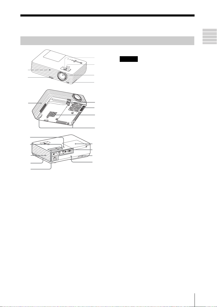
Location and Function of Controls
Main Unit
qg
5
9
qk
qj
qh
qg
f
a Focus ring (page 11)
b Zoom ring (page 11)
c Lens
d Remote control detector
e Foot adjust button (page 13)
0
qa
qs
qd
1
2
3
6
7
qg
i Ventilation holes (exhaust)
Overview
Caution
Do not place anything near the ventilation
holes as this may cause internal heat
buildup. Do not place your hand near the
ventilation holes and the circumference as
this may cause injury.
j Lamp cover (page 34)
k Terminal panel (page 4)
l Security bar
Connects to a commercially available
security chain or wire.
m Security lock
Connects to an optional security cable
manufactured by Kensington.
For details, visit Kensington’s web site.
http://www.kensington.com/
n Control panel keys (page 5)
o Ventilation holes (intake)
p Speaker
q WARNING indicator (page 29)
r ON/STANDBY indicator
(page 29)
f Front foot (adjustable) (page 13)
g Air filter cover/Ventilation holes
(intake) (page 36)
h Rear feet (page 13)
Location and Function of Controls
3
Page 4
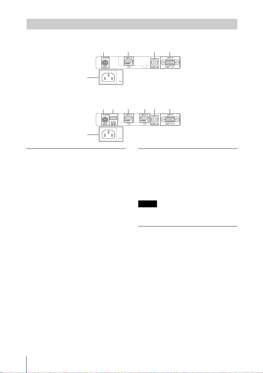
Terminal Panel
VPL-DX220
7
VPL-DX240/DX270/DW240
7
4 126
42 1356
Input (pages 7, 8)
a INPUT A
Video: RGB/YPBPR input terminal
b INPUT B
Video: HDMI input terminal
Audio: HDMI input terminal
c INPUT C*
Video: HDMI input terminal
Audio: HDMI input terminal
* VPL-DX240/DX270/DW240 only
d VIDEO IN
Video: Video input terminal
Output
e Power Supply*
USB terminal (Type A)(5V/2A)
* VPL-DX240/DX270/DW240 only
f AUDIO OUTPUT
Audio: Audio output terminal (AUDIO)
Note
The audio is output only when the INPUT B
terminal or the INPUT C terminal is selected.
Others
g AC IN (∼) socket
Connects the supplied AC power cord.
4
Location and Function of Controls
Page 5
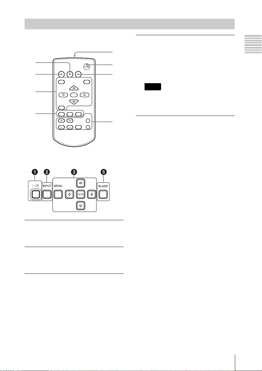
Remote Commander and Control Panel Keys
Remote Commander
7
4
INPUT
APA ECO MODE
2
3
4
Control Panel Keys
a Turning on the power/Going to
standby mode
?/1 (On/Standby) key
MENU
RETURN
ASPECT
D ZOOM
KEYSTONE
VOLUME
ENTER
PATTERN
FREEZE
RESET
BLANK
MUTING
1
6
5
d Adjusting the image (page 11)
ASPECT key (page 19)
KEYSTONE key (page 14)
PATTERN key (page 12)
APA (Auto Pixel Alignment) key
*
(page 14)
Note
Use this key when inputting a computer
*
signal via the RGB input terminal
(INPUT A).
e Using various functions during
projecting
D ZOOM (Digital Zoom) +/– key
*1
Enlarges the image with the center of it
as a starting point while projecting.
1 Press the D ZOOM + key to display
the digital zoom icon on the projected
image.
2 Press the V/v/B/b keys to move the
digital zoom icon to the point on the
image you want to enlarge.
3 Press the D ZOOM + key or the D
ZOOM – key repeatedly to change the
enlargement ratio. The image can be
enlarged up to 4 times.
Press the RESET key to restore the
previous image.
Overview
b Selecting an input signal
(page 10)
INPUT key
c Operating a menu (page 17)
MENU key
RESET key
ENTER /V/v/B/b (arrow) keys
RETURN key
Location and Function of Controls
5
Page 6
BLANK key
Cuts off the projected image
temporarily. Press again to restore the
previous image. Picture muting helps
reduce power consumption.
MUTING key
Mutes the audio output temporarily.
Press again to restore the previous
volume.
VOLUME +/– key
Adjusts the volume output.
FREEZE key
*2
Pauses a projected image. Press again to
restore the image.
Notes
*1: Use this key when inputting a
computer signal. But it may not be
used depending on the resolution of
the input signal.
*2: Use this key when inputting a
computer signal.
f Setting the energy–saving mode
easily
ECO MODE key
Energy-saving mode can be set easily.
Energy-saving mode consists of “Lamp
Mode,” “With No Input,” and “With
Static Signal.”
1 Press the ECO MODE key to display
the ECO Mode menu.
ECO Mode Menu
ECO Mode
ECO
User
RETURN
:Sel
:Back
2 Press the V/v key or ECO MODE key
to select “ECO” or “User” mode.
ECO: Sets each mode to the optimum
energy-saving value.
Lamp Mode: Low
With No Input: Standby
With Static Signal: Lamp
Dimming
User: Sets each item of the ECO
mode menu as you desire (go to
step 3).
3 Select “User” then press the b key.
The setting items appear.
User
Lamp Mode High
Auto Power Saving
With No Input
With Static Signal
:Sel
:Set
Off
Lamp Dimming
RETURN
:Back
4 Press the V/v key to select the item
then press the ENTER key.
5 Press the V/v key to select the setting
value.
6 Press the ENTER key.
The screen returns to the previous
menu.
For details on ECO Mode settings, see
“Lamp Mode”, “With No Input” and
“With Static Signal” on the Connection/
Power menu (page 25).
g Infrared transmitter
About remote commander operation
• Direct the remote commander toward the
remote control detector.
• The shorter the distance between the
remote commander and the projector is,
the wider the angle within which the
remote commander can control the
projector becomes.
• Make sure that nothing obstructs the
infrared beam between the remote
commander and the remote control
detector on the projector.
6
Location and Function of Controls
Page 7
B Preparation
Connecting the Projector
Notes
• Make sure all the equipment is powered off when connecting the projector.
• Use the proper cables for each connection.
• Insert the cable plugs firmly; Loose connections may reduce performance of picture signals or
cause a malfunction. When pulling out a cable, be sure to grip it by the plug, not the cable itself.
• For more information, refer also to the instruction manuals of the equipment you are connecting.
• Use a no-resistance audio cable.
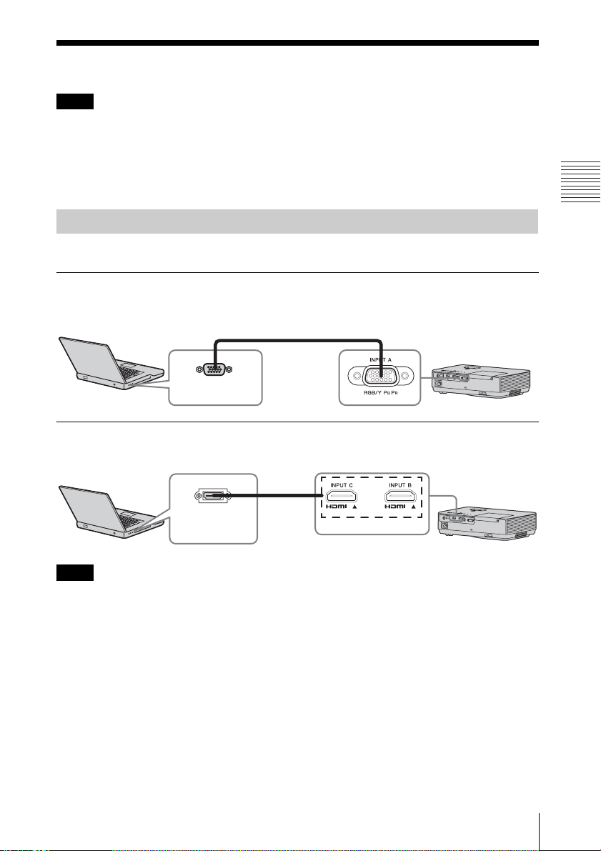
Connecting a Computer
Connection with a computer is explained for each input signal.
INPUT A
For connecting a computer with an RGB output terminal.
Mini D-sub 15-pin cable (supplied)
RGB output
Computer
INPUT B/INPUT C
For connecting a computer with an HDMI output terminal.
terminal
Preparation
HDMI output
terminal
Computer
Notes
• Only VPL-DX270/DX240/DW240 has the INPUT C terminal.
• Use HDMI-compatible equipment and cable(s) that have an HDMI logo on them.
• Use a high speed HDMI cable(s) on which the cable type logo is specified. (Sony products are
recommended.)
• The HDMI terminal of this projector is not compatible with DSD (Direct Stream Digital) Signal
or CEC (Consumer Electronics Control) Signal.
• The resolutions of the projected image may vary depending on the input terminals.
• It is recommended that you set the resolution of your computer to 1024 × 768 pixels (VPL-DX270/
DX240/DX220) or 1280 × 800 pixels (VPL-DW240) for the external monitor.
HDMI
cable (not
supplied)
Connecting the Projector
7
Page 8
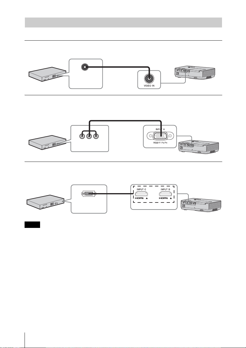
Connecting a Video equipment
Connections with a DVD player or BD player are explained for each input signal.
VIDEO
For connecting video equipment with a video output terminal.
Video cable (not supplied)
Video output
terminal
Video equipment
INPUT A
For connecting video equipment with a YPBPR output terminal.
Component – Mini D-sub 15-pin cable (not supplied)
BPR output
YP
terminal
Video equipment
INPUT B/INPUT C
For connecting video equipment with an HDMI output terminal.
HDMI output
terminal
Video equipment
Notes
HDMI
cable
(not
supplied)
• Only VPL-DX270/DX240/DW240 has the INPUT C terminal.
• Use HDMI-compatible equipment and cable(s) that have an HDMI logo on them.
• The HDMI terminal of this projector is not compatible with DSD (Direct Stream Digital) Signal
or CEC (Consumer Electronics Control) Signal.
• Use a high speed HDMI cable(s) on which the cable type logo is specified. (Sony products are
recommended.)
• The maximum resolution of the INPUT C terminal is set to 720p.
8
Connecting the Projector
Page 9
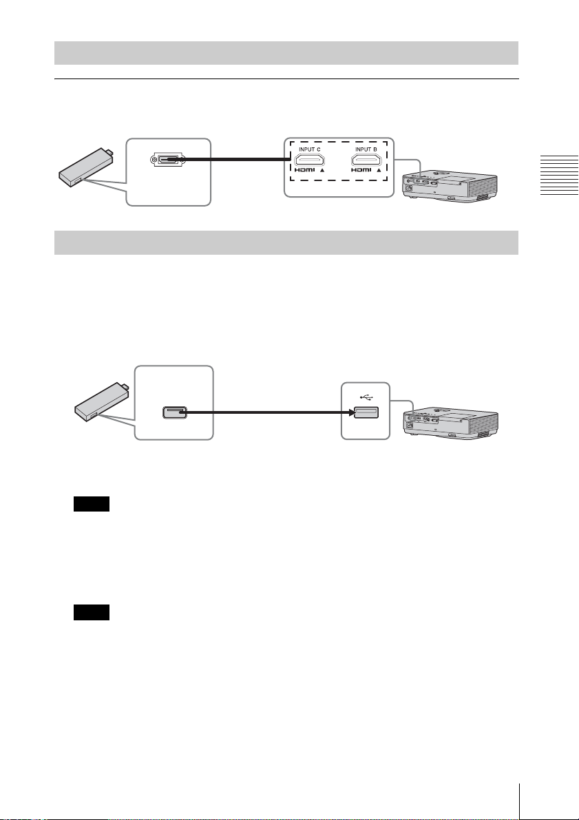
Connecting to an external device
INPUT C
For connecting an external device with an HDMI output terminal. Connect the external device
to INPUT C.
HDMI cable
(not supplied)
External
device
HDMI output
terminal
Supplying the power to the external device
The unit supplies power (5V/2A maximum) via the USB cable to the external device (stick type
PC, etc.).
1 Connect the unit to the external device using the USB cable (with type A USB
terminal).
USB terminal
(Type A)
Stick type external devices with HDMI
output terminal, such as wireless devices,
small-sized PC, etc. (not supplied)
Notes
• Use external devices with the appropriate specification for using this unit.
• If you connect the unit in wrong ways, the external device may cause a malfunction. In this
case, Sony assumes no responsibility.
USB cable
(type A USB terminal)
Power supply
terminal
Preparation
2 Set “Power Supply” to “On” in the Connection/Power menu (page 25).
The unit supplies power to the external device through the USB cable.
Notes
• Only VPL-DX270/DX240/DW240 has the INPUT C terminal.
• Use HDMI-compatible equipment and cable(s) that have an HDMI logo on them.
• The HDMI terminal of this projector is not compatible with DSD (Direct Stream Digital)
Signal or CEC (Consumer Electronics Control) Signal.
• Use a high speed HDMI cable(s) on which the cable type logo is specified. (Sony products are
recommended.)
• The maximum resolution of the INPUT C terminal is set to 720p.
Connecting the Projector
9
Page 10
B Projecting an Image
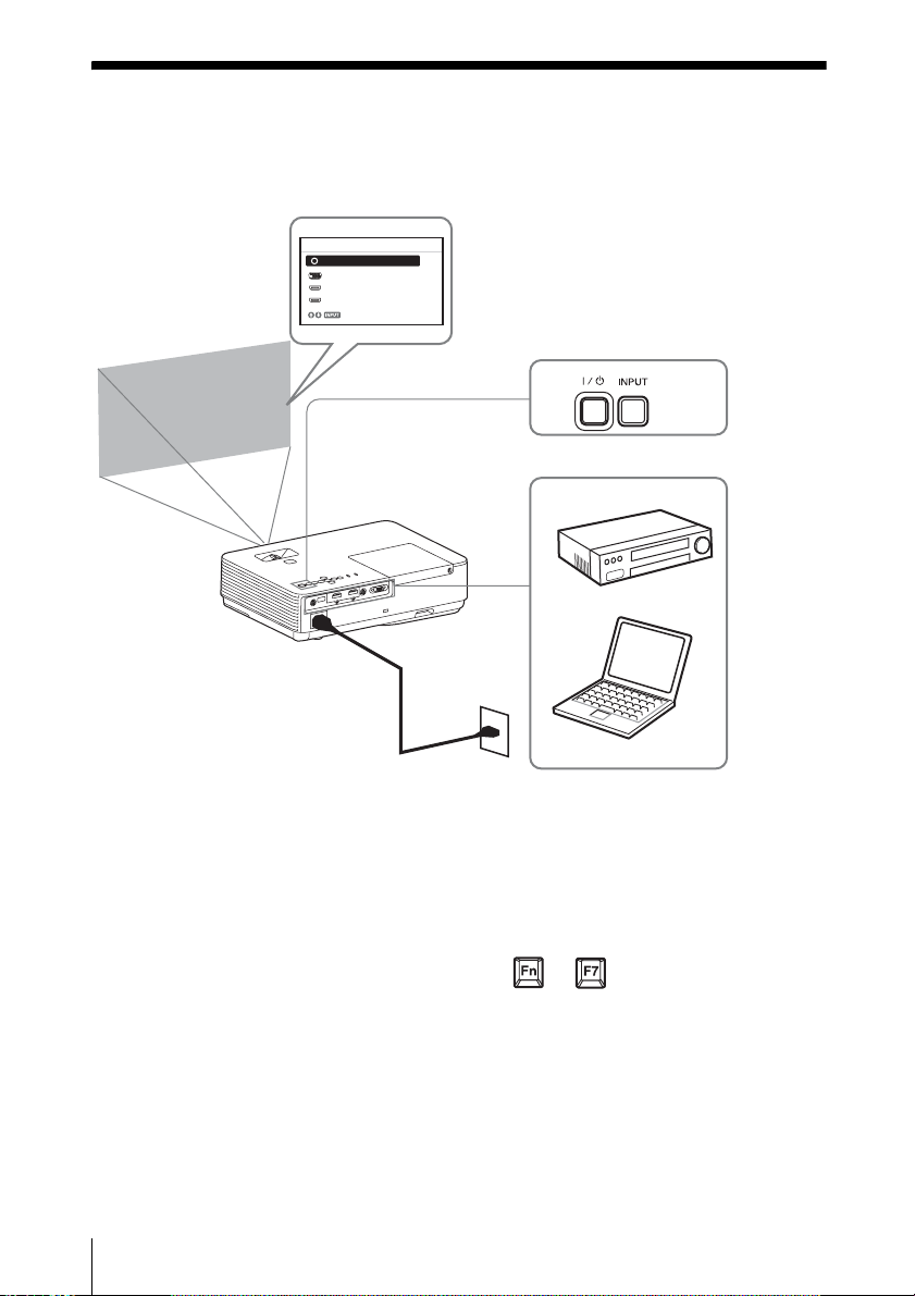
Projecting an Image
The size of a projected image depends on the distance between the projector and screen. Install
the projector so that the projected image fits the screen size. For details on projection distances
and projected image sizes, see
Projector
“Projection Distance” (page 44).
Input
Video
Input-A
Input-B
Input-C
Sel
2
3
4
Video equipment
5
1 Plug the AC power cord into the wall
outlet.
2 Connect all equipment to the projector
(page 7).
3 Press the ?/1 key to turn on the unit.
4 Turn on the connected equipment.
5 Select the input source.
Press the INPUT key on the projector to
display the menu for switching input
signal on the screen. Press the INPUT
key repeatedly, or press the
select an image to be projected.
10
Projecting an Image
1
V/v key to
Wall outlet
Computer
6
6 When projecting a computer image,
switch your computer’s output to
external display.
The method to switch the output varies
depending on the type of computer.
(Example)
+
7 Adjust the focus, size and position of
the projected image (page 11).
Page 11
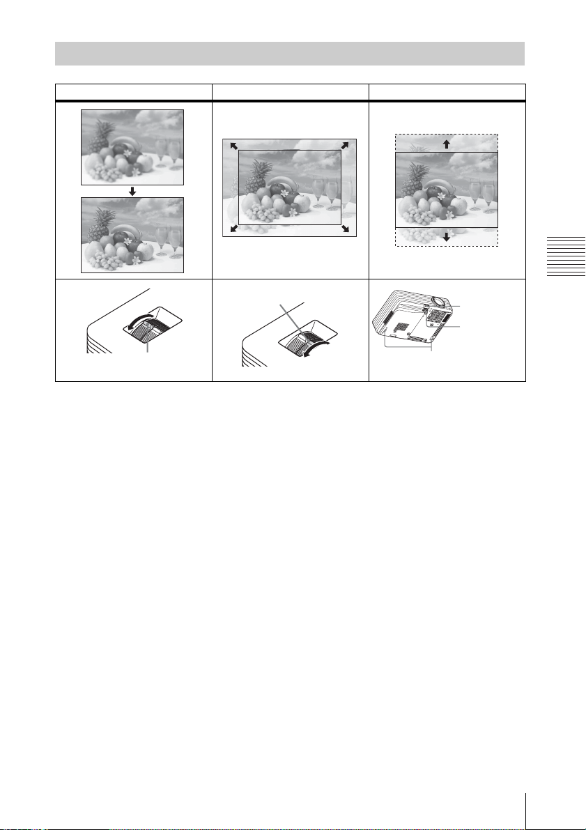
Adjusting the Projected image
Focus Size (Zoom) Position
Focus ring
Zoom ring
Foot adjust
Projecting an Image
button
Front foot
(adjustable)
Rear feet
Projecting an Image
11
Page 12
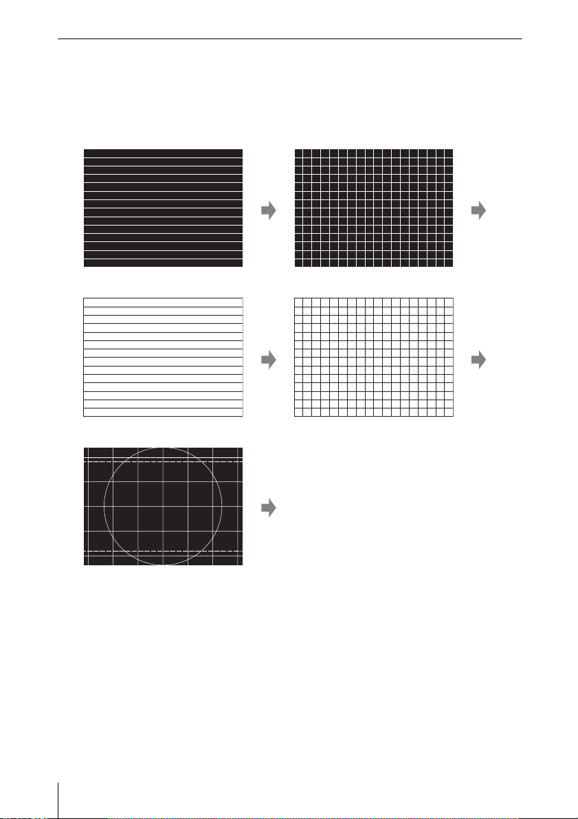
Display the templates and patterns for adjusting an image
Press the PATTERN key of the remote control to display the templates and patterns for
adjusting an image on the projected image. There are four templates and one pattern. Every
time you press the PATTERN key, the templates/pattern switch. Press the MENU button to
return to the previous image.
Template 1 Template 2
Template 3 Template 4
Pattern for adjusting an image
12
Projecting an Image
Returns to the previous image.
Page 13
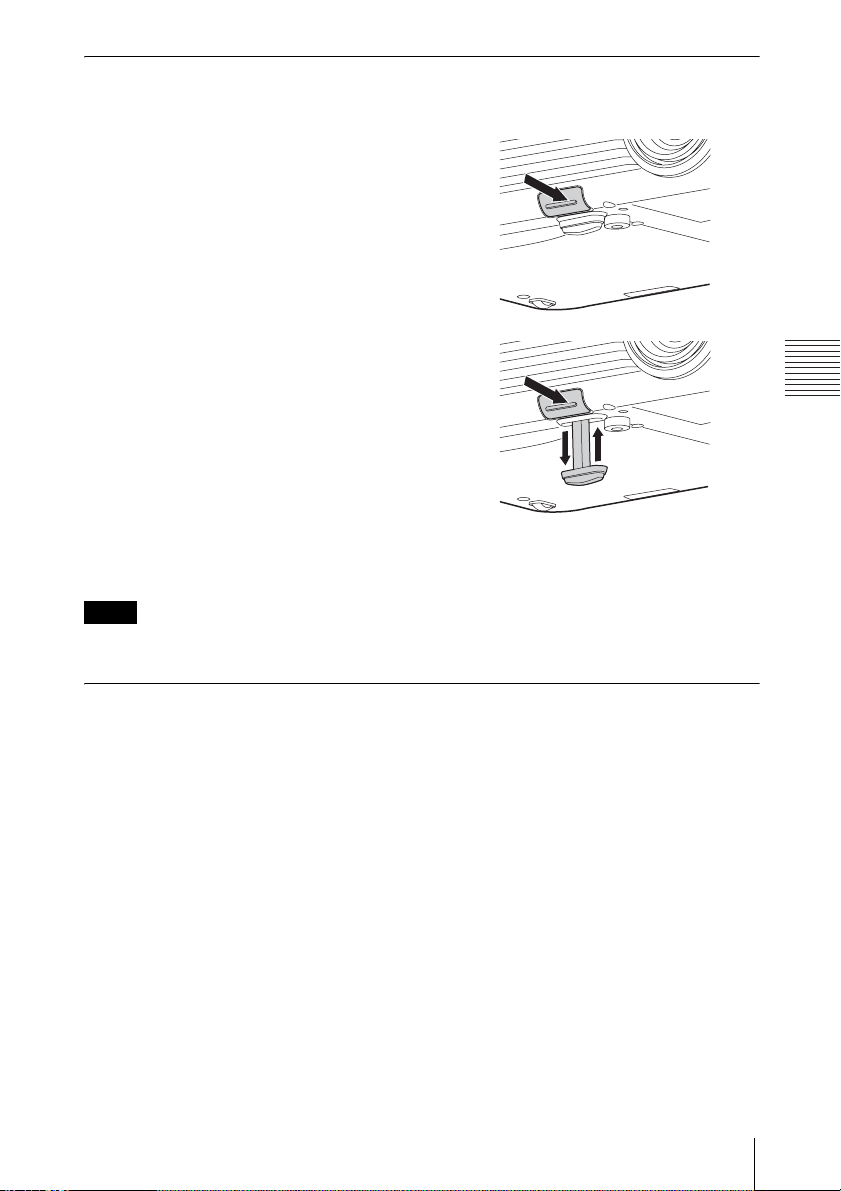
Adjusting with the foot adjust button
You can adjust the position of the projected image by tilting the projector with the foot adjust
button.
1 Press and hold the foot adjust button,
then lift up the front of the projector to
adjust the angle.
2
When the desired angle is achieved,
release the foot adjust button to lock the
position.
Notes
• Be careful not to let the projector down on your fingers.
• Do not push hard on the top of the projector with the front foot (adjustable) extended.
Projecting an Image
Changing the aspect ratio of the projected image
Press the ASPECT key on the remote commander to change the aspect ratio of the projected
image. You can also change the setting in Aspect of the Screen menu (pages 19, 21).
Projecting an Image
13
Page 14
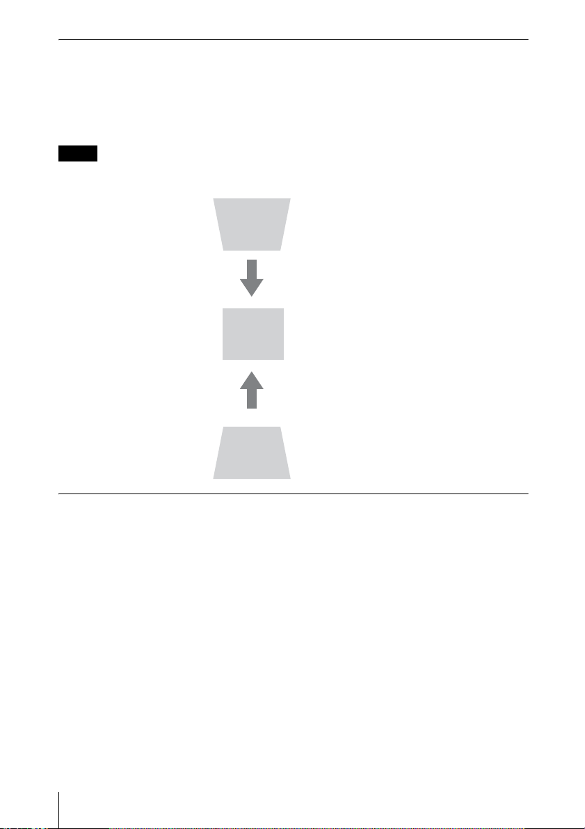
Correcting trapezoidal distortion of the projected image (Keystone feature)
Keystone feature may not work automatically*2 when the screen is tilted. In this case, set
keystone manually.
1 Press the KEYSTONE key on the remote commander or select V Keystone in the Installation
menu.
2 Use the V/v/B/b the keys to set the value. The higher the value, the narrower the top of the
projected image. The lower the value, the narrower the bottom.
Notes
*1: Since the Keystone adjustment is an electronic correction, the image may be deteriorated.
*2: VPL-DX270/DX240/DW240 only.
Increase the num ber
towards plus
Increase the number
towards minus
*
1
Automatically adjusts Phase, Pitch and Shift of projected image while a
signal is input from a computer (APA (Auto Pixel Alignment))
Press the APA key on the remote commander. Press again to cancel adjusting during the setting.
You can also set APA in the Screen Menu (page 20). If Smart APA in the Function menu is set
to “On”, executes APA automatically when a signal is input (page 23).
14
Projecting an Image
Page 15
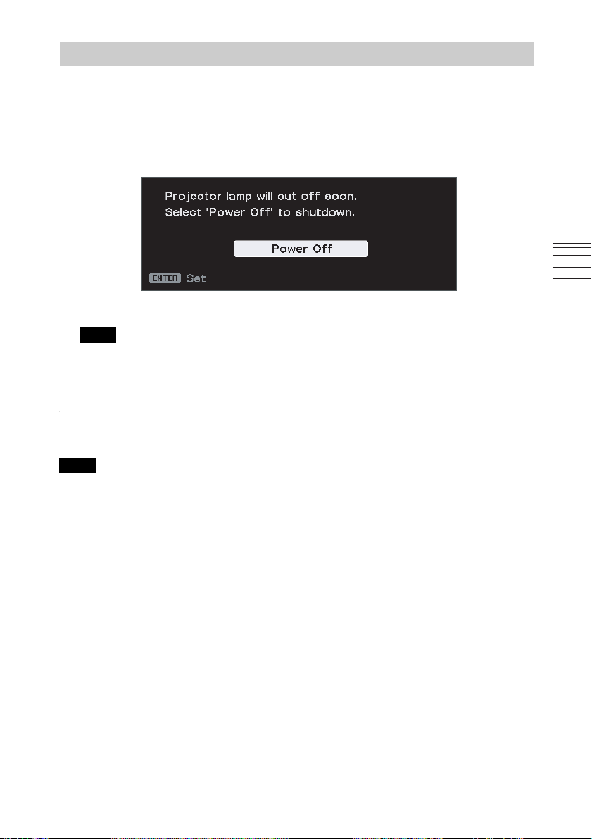
Turning Off the Power
1 Press the ?/1 key on the unit or the remote commander.
The projector starts shutdown and turns off. If you press the ?/1 key within 10 seconds of
the message being displayed, shutdown is canceled.
When “Power Supply” is set to “On,” press start to display the message. After about ten
seconds, the lamp will turn off, and the unit continues to supply power. Select “Select
'Power Off' to shutdown.” to stop supplying power.
Press the power button while the message is displayed to light the lamp again.
Note
Do not turn off the projector soon after the lamp lights. It may cause a malfunction of the lamp
(does not light ,etc.).
2 Unplug the AC power cord from the wall outlet.
Turning off without displaying the confirmation message
Press and hold the ?/1 key on the unit for a few seconds (page 31).
Projecting an Image
Note
If you turn off the unit soon after the lamp is turned on, the confirmation message will be
displayed and may take a longer time for the unit to turn off.
Projecting an Image
15
Page 16
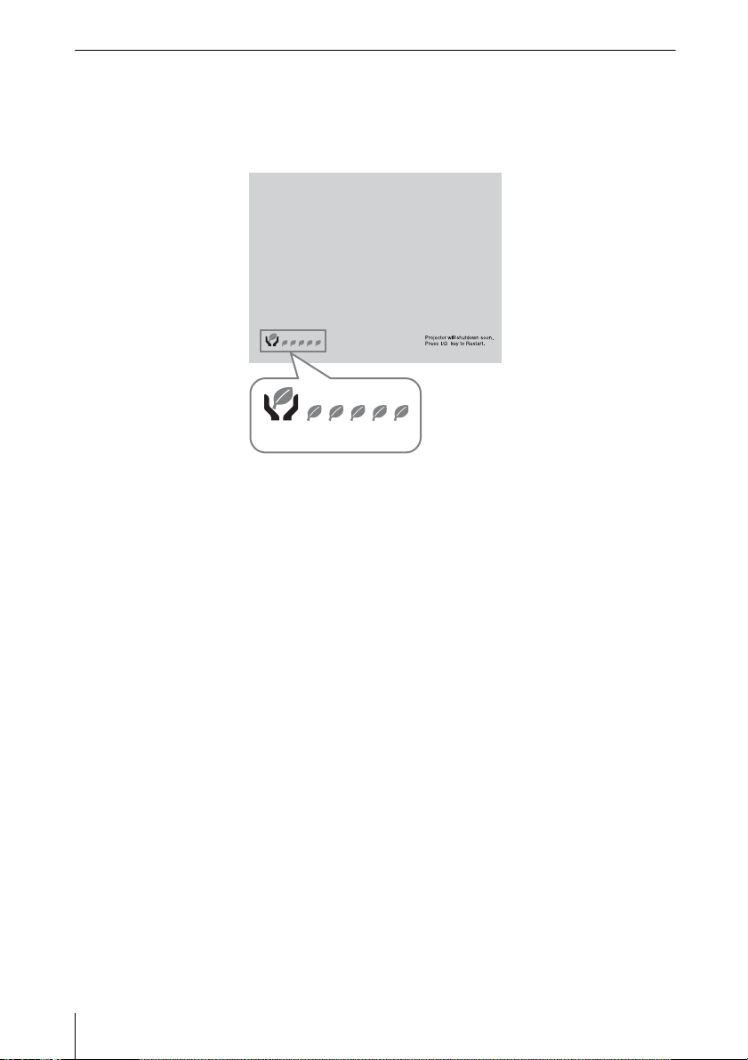
ECO gauge
This gauge indicates the current effectiveness of the projector’s ECO function.
(For details on the ECO function, see “ECO MODE key” (page 6) and “ECO” (page 25).)
The leaf icons are displayed when the projector is shut down. The number of displayed icons
varies according to how much energy is saved as a result of using the ECO function.
ECO gauge
16
Projecting an Image
Page 17
B Adjustments and Settings Using a Menu
Using a MENU
Note
The menu displays used for the explanation below may be different depending on the model you are
using.
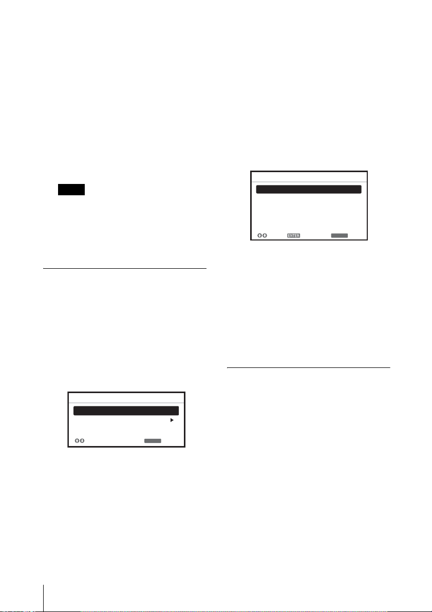
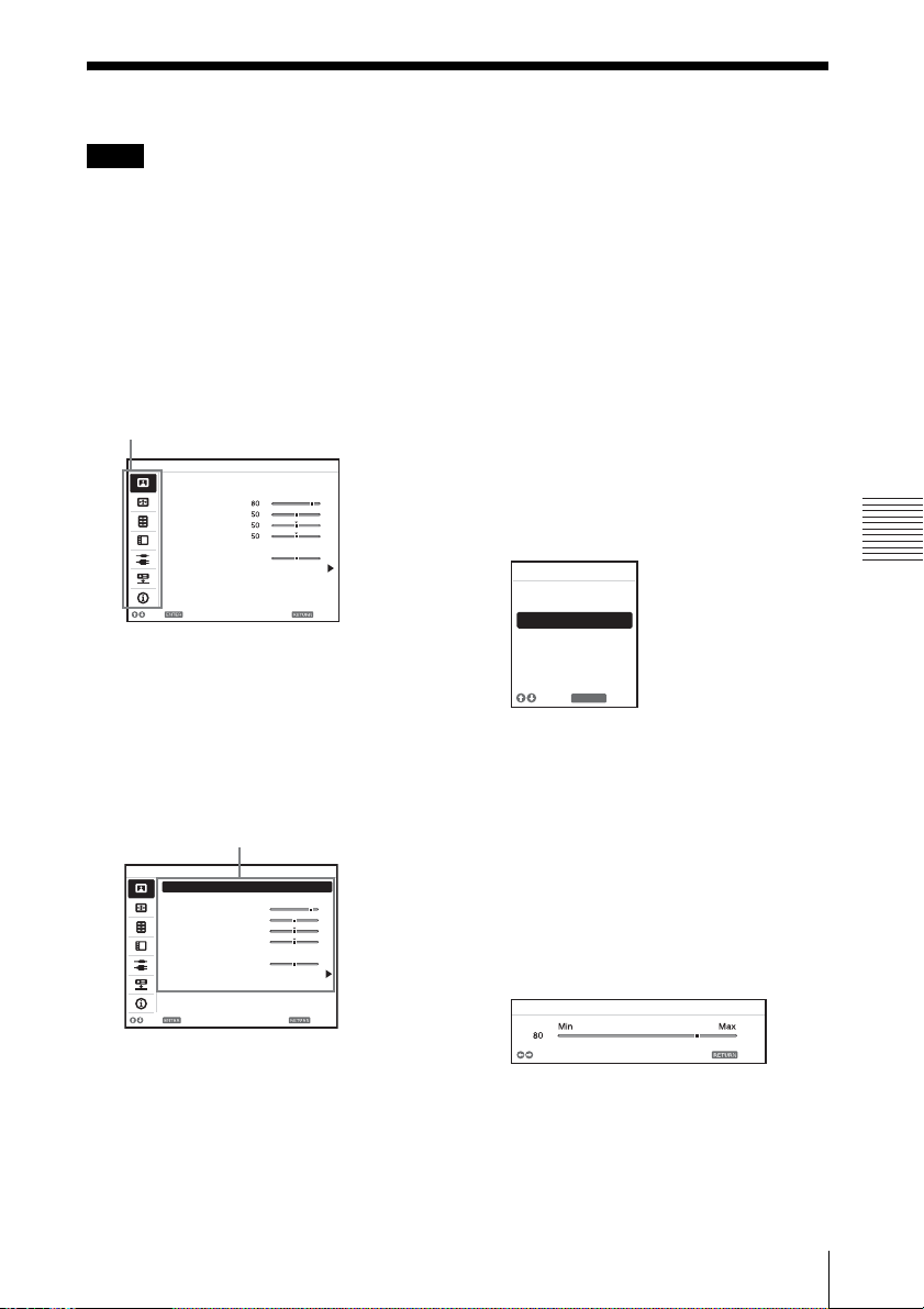
1 Press the MENU key to display the
menu.
2 Select the setting menu.
Use the V/v key to select the setting
menu then press the b key or ENTER
key.
Setting menu
Picture
Picture Mode Standard
Reset
Contrast
Brightness
Color
Hue
Color Temp.
Sharpness
Expert Setting
:Sel :Set :Back
Low
30
3 Select the setting item.
Use the V/v key to select the setting
menu then press the b key or ENTER
key.
To return to the selection screen of the
setting menu, press the B or RETURN
key.
Setting items
Picture
Picture Mode Standard
Reset
Contrast
Brightness
Color
Hue
Color Temp.
Sharpness
Expert Setting
:Sel :Set :Back
80
50
50
50
Low
30
4 Make the setting or adjustment for the
selected item.
The setting method varies, depending on
the setting item.
If the next menu window is displayed,
select the item according to the
operations in step 3 and then press the
ENTER key to register the setting.
To return to the selection screen of the
setting items, press the B or RETURN
key. As an aid to setting or adjusting
items, you can press the RESET key to
return an item to its factory setting.
Using a pop-up menu
Press the V/v/B/b key to select an item.
A selected item takes effect
immediately, except “Language”, which
will take effect after you press the
ENTER key.
Picture Mode
Vivid
Dynamic
Standard
Presentation
Blackboard
Whiteboard
Cinema
:Sel
RETURN
:Back
Using the setting menu
Press the V/v key to select the item.
A selected item takes effect
immediately. The previous screen is
restored.
Using the adjustment menu
To increase the value, press the V/b key
and to decrease the number, press the
v/B key. If you press the ENTER key,
the selected item takes effect
immediately. The previous screen is
restored.
Contrast
Adjust
Back
5 Press the MENU key to clear the
menu.
The menu disappears automatically if no
operation is performed.
Adjustments and Settings Using a Menu
Using a MENU
17
Page 18

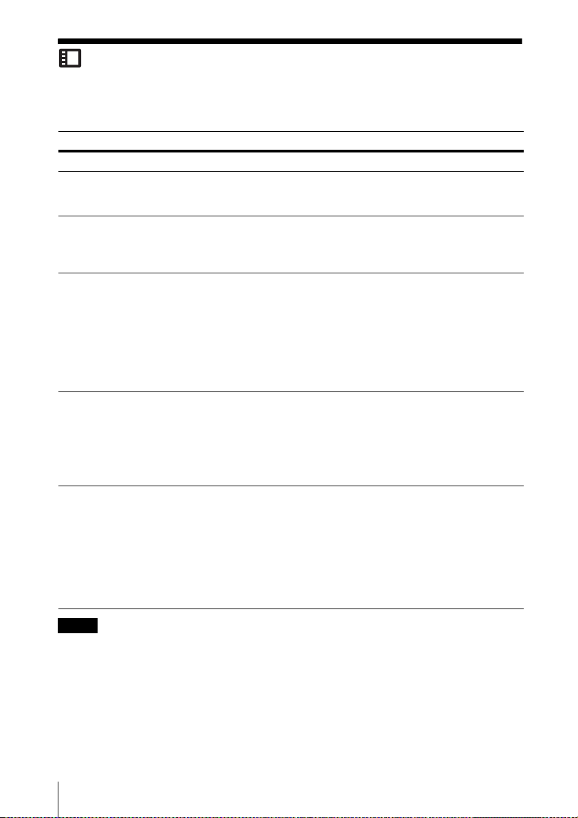
The Picture Menu
The Picture menu is used to adjust the picture for each input signal.
Items Item descriptions
Picture Mode Vivid: Projects the image with a bright, explicit, and vivid picture.
*2
Reset
Contrast The higher the value, the greater the contrast. The lower the value, the lower
Brightness The higher the value, the brighter the picture. The lower the value, the darker
*3 *4
Color
*3 *4 *5
Hue
Color Temp.
Sharpness The higher the value, the sharper the picture becomes. The lower the value, the
Expert Setting
Gamma
*1 *7
Mode
Dynamic: Emphasizes the contrast to produce a dynamic and vivid picture.
Standard: Provides an image which is natural and well balanced.
Presentation
Blackboard: Provides an image suitable for displaying on a blackboard.
Whiteboard: Provides an image suitable for displaying on a whiteboard.
Cinema: Provides an image suitable for viewing movies.
Resets to the factory setting.
the contrast.
the picture.
The higher the value, the greater the intensity. The lower the value, the lower
the intensity.
The higher the value, the more greenish the picture becomes. The lower the
value, the more reddish the picture becomes.
*6
High/Middle 1/Middle 2/Low: The higher the value, the more bluish the
picture becomes. The lower the value, the more reddish the picture becomes.
softer the picture becomes.
Graphics 1: Gamma correction to make halftones brighter. This setting is
suitable when projecting highly colorful images, such as photos, in a bright
place.
Graphics 2: Gamma correction to improve the reproduction of halftones.
Highly colorful images, such as photos, can be reproduced in natural tones.
Graphics 3: Selects gamma correction to emphasize bright parts. Projects
images explicitly.
*1
: Provides a bright image, suitable for presentations.
Notes
*1: When a computer signal is input, this option is available.
*2: The settings in the Picture menu return to their factory defaults, except for “Picture Mode”.
*3: When a video signal is input, this option is available.
*4: When the signal without color burst signal is input, this option is unavailable.
*5: When an analog TV signal is input, this option may not available, depending on the color system.
*6: When “Picture Mode” is set to the item other than “Presentation” or “Blackboard,” this option
is available.
*7: When “Picture Mode” is set to “Blackboard,” this option is unavailable.
18
The Picture Menu
Page 19

The Screen Menu
The Screen menu is used to adjust the size, position and aspect ratio of the projected image for
each input signal.
Items Item descriptions
*1
Aspect
VPL-DX270/DX240/
DX220: When the
computer signal is
input
VPL-DX270/DX240/
DX220: When the
video signal is input
VPL-DW240: When
the computer signal is
input
VPL-DW240: When
the video signal is
input
Changes the aspect ratio of the projected image (page 21).
4:3: Displays the image to fit the maximum projected image size
with an aspect ratio fixed to 4:3.
16:9: Displays the image to fit the maximum projected image size
with an aspect ratio fixed to 16:9.
Full 1: Displays the image to fit the maximum projected image
size without changing the aspect ratio of the input signal.
Normal: Displays the image on the center position of the
projected image without changing the resolution of the input
signal or enlarging the image.
4:3: Displays the image to fit the maximum projected image size
with an aspect ratio fixed to 4:3.
16:9: Displays the image to fit the maximum projected image size
with an aspect ratio fixed to 16:9.
Zoom: Zooms the center area of a projected image.
4:3: Displays the image to fit the maximum projected image size
with an aspect ratio fixed to 4:3.
16:9: Displays the image to fit the maximum projected image size
with an aspect ratio fixed to 16:9.
Full 1: Displays the image to fit the maximum projected image
size without changing the aspect ratio of the input signal.
Full 2: Displays the image to fit the maximum projected image
size changing the aspect ratio of the input signal.
Full 3: Displays the image to fit the maximum width or height, up
to 1280 × 720 pixels, without changing the aspect ratio of the
input signal.
Normal: Displays the image on the center position of the
projected image without changing the resolution of the input
signal or enlarging the image.
4:3: Displays the image to fit the maximum projected image size
with an aspect ratio fixed to 4:3.
16:9: Displays the image to fit the maximum projected image size
with an aspect ratio fixed to 16:9.
Full: Displays the image to fit the maximum projected image size
changing the aspect ratio of the input signal.
Zoom: Zooms the center area of a projected image.
Adjustments and Settings Using a Menu
The Screen Menu
19
Page 20

Items Item descriptions
Adjust Signal Adjusts the image of a computer signal. Use this item if the edge
of the image is cut, or is not displayed properly.
APA
*2 *3
Automatically adjusts the projected image to an optimum quality
when you press the ENTER key (page 5).
*2
Phase
Adjusts the dot phase of the display pixel and the input signal. Set
to the value where looks clearest.
*2
Pitch
The higher the value, the wider the horizontal image elements
(pitch). The lower the value, the narrower the horizontal image
elements (pitch).
*2
Shift
H (Horizontal): The higher the value, the farther right the image
is projected on the screen. The lower the value, the image farther
left.
V (Vertical): The higher the value, the farther up the image is
projected on the screen. The lower the value, the image farther
down.
Notes
*1: • Note that if the projector is used for profit or for public viewing, modifying the original picture
by switching to the aspect mode may constitute an infringement of the rights of authors or
producers, which are legally protected.
• Depending on the input signal, setting items for aspect ratio or some other setting items cannot
be set in some cases, or changing the aspect ratio setting may have no effect.
• A part of the image may be displayed in black, depending on the setting item.
*2: Available when a computer signal is input from the RGB input terminal (INPUT A).
*3: If the projected image includes large amount of black portion around it, the APA function will
not work properly and a part of the image may not be displayed on the screen and also optimum
image cannot be obtained, depending on the type of input signal. In this case, adjust the “Phase,”
“Pitch,” and “Shift” items manually.
20
The Screen Menu
Page 21

Aspect
VPL-DX270/DX240/DX220
Input signal Recommended
4:3
16:9
Computer signal
16:10 Full1
4:3 4:3*3
setting value and
projected image
*1
Full1
*1 *2
Full1
*1 *2
*1: If you select “Normal,” the image is
projected in the same resolution as the
input signal without changing the aspect
ratio of the original image.
*2: If you select “4:3,” the image is projected
to fit the projected image size, regardless
of the aspect ratio of the image.
*3: Depending on the input signal, the
projected image may be projected as
illustrated below. In this case, select
“16:9.”
*4: Depending on the input signal, the
projected image may be projected as
illustrated below. In this case, select
“Zoom.”
Adjustments and Settings Using a Menu
16:9 16:9
*4
Video signal
The Screen Menu
21
Page 22

VPL-DW240
Input signal Recommended
setting value and
projected image
4:3 Full1
16:9 Full1
*1 *2 *3
*1 *2 *3
*1: If you select “Normal,” the image is
projected in the same resolution as the
input signal without changing the aspect
ratio of the original image.
*2: If you select “Full2,” the image is projected
to fit the projected image size, regardless
of the aspect ratio of the image.
Computer signal
16:10 Full1
*3
*3: If you adjust the projected image position
using an image with 16:9 aspect ratio and
then switch the input source to 4:3 image,
the top and bottom edge of the image may
be hidden. In this case, select “Full3.”
4:3 4:3
*4 *5
*4: Depending on the input signal, the
projected image may be projected as
illustrated below. In this case, select
“16:9.”
16:9 16:9
Video signal
*5: Depending on the input signal, the image
may be projected as illustrated below. In
this case, select “Zoom.”
22
The Screen Menu
Page 23

The Function Menu
The Function menu is used for setting various functions of the projector.
Items Item descriptions
Presentation Timer Timer Set/Start: Sets the projecting time with the timer. Press the
Size Fixed Small/Fixed Large/Auto: Selects the character size of the
Position Bottom Right/Bottom Left/Top Right: Selects the position of the
Count UP/Down Up/Down: Selects counting up or counting down of the set time.
Volume The higher the value, the louder an audio volume and the lower the
Smart APA On/Off: When set to “On,” APA functions automatically when a
CC Display Off: Closed caption does not appear.
Lamp Timer Reset When replacing the lamp, resets the lamp timer (page 34).
Start Up Image On/Off: When set to “On,” the Start Up Image is displayed on the
Note
*1: APA functions when a computer signal is input via the RGB input terminal (INPUT A).
ENTER key to start counting.
timer. When set to “Auto,” the timer with the larger characters will be
displayed for three seconds once every minute (approx.). It informs the
passing of time to the presenter.
timer.
value, the lower the audio volume.
signal is input.
CC1/CC2/CC3/CC4/Text1/Text2/Text3/Text4: Selects the closed
caption service (captions or text).
screen when the projector is powered on.
*1
Adjustments and Settings Using a Menu
The Function Menu
23
Page 24
The Operation Menu
The Operation menu is used for setting for the operations by using the menu or the remote
commander.
Items Item descriptions
Language Selects the language used in the menu and messages.
Status On: All on-screen statuses are enabled.
Set Password 1 Input the password with the MENU, V/v/B/b and ENTER keys. (The
Security Lock
Menu Settings
*2
Lock
Control Key
Lock
Off: Turns off the on-screen displays, except for menus, warning messages
and messages from the message list.
default setting password is “ENTER, ENTER, ENTER, ENTER.”)
2 Input a new password with the MENU, V/v/B/b and ENTER keys.
3 Enter the password again to confirm.
*1
On/Off: This function enables restriction of the projector to authorized users
by password. The setting procedures for security locking are as follows:
1 Select “On” and press the ENTER key to display the setting menu.
2 Input the password that is already set.
When it is set to “Off,” you can cancel the security lock. You are required to
input the password again.
If you fail to enter the correct password after three consecutive times, the
projector cannot be used. In this case, press the ?/1 key to go Standby mode
then turn on the power again.
Full: Locks all menu settings.
Startup: If this setting is set, the settings when the unit is turned on will be
locked. The settings can be changed when using the unit. If the unit is turned
off, the unit restores the initial settings (which are locked when the unit was
turned on).
Update: While set to “Startup,” the changed settings will be saved and locked
by selecting “Update.”
On/Off: When set to “On,” locks all the control panel keys of the projector.
However, you can operate the following when set to “On”:
• Press and hold the ?/1 key for approximately 10 seconds during Standby
mode.
c The projector turns on.
• Press and hold the MENU key for approximately 10 seconds during power
on.
c “Control Key Lock” is set to “Off” and enables operation of all keys on
the projector.
Notes
*1: You will not be able to use the projector if you forget your password. If you call qualified Sony
personnel because you have forgotten the password, you will be asked to verify the projector’s
serial number and your identity. (This process may differ in other countries/regions.) Once your
identity has been confirmed, we will provide you with the password.
*2: Before operating this menu, it is necessary to input the password. Set the password in “Set
Password” (page 24) of the Operation menu.
24
The Operation Menu
Page 25

The Connection/Power Menu
The Connection/Power menu is used for setting for the connections and power.
Items Item descriptions
ECO
*5
Lamp Mode High/Standard/Low/Auto
Power Supply Off/On: When set to “On,” the unit supplies power to the external
Auto Power Saving
With No Input Auto: The lamp turns off automatically and power consumption is
With Static
Signal
Input-A Signal Sel.
Direct Power On On/Off: When set to “On,” you can turn the power on without going to
Cooling Time Standard/Quick: Sets the duration of unit cooling after turning off the
brighter, and power consumption becomes higher. When set to “Low,”
power consumption is minimized; however, the image will be darker.
When set to “Auto,” brightness is adjusted automatically according to
image content. Dark images are projected with brightness adjusted,
leading to energy-saving. Bright images are projected brightly, without
adjusting brightness.
device (stick type PC, etc.) through the USB cable. For power supply,
see “Supplying the power to the external device” (page 9).
reduced if no signal is input for more than about 10 minutes.
The lamp lights again when a signal is input or any key is pressed. After
the lamp turns off, the ON/STANDBY indicator lights in orange
(page 30).
Standby
minutes, the power turns off automatically, and the unit enters standby
mode.
Off: You can deactivate the With No Input.
Lamp Dimming
10 seconds, lamp output is gradually reduced (approximately 10% to
15%
darkens to approximately 30% of its lamp output according to the
selected time (with no change to input signal) “5,” “10,” “15,” “ 20”
minutes or “Demo.,” While dimming the lamp, the message “Lamp
Dimming” appears. If you select “Demo.,” the image will start to
darken about 40 seconds later. When any change in signal is detected,
or an operation (remote control or control panel) is performed, normal
brightness is restored.
Off: You can deactivate the With Static Signal.
*1
Auto/Computer/Component/Video GBR:
the type of video signal input automatically when “Input-A” is selected.
Standby mode when the AC power cord is connected to a wall outlet.
With the projector turned off, you can also unplug the AC power cord
without going to Standby mode, regardless of the Direct Power On
setting.
lamp. If set to “Standard,” the temperature of the unit will be cooled
enough to be carried.
*2
: If no signal is input to the unit for more than about 10
*4*5
*3
) from that set in the Lamp Mode. Automatically the lamp slowly
: When set to “High,” the image becomes
*6
: If an image does not change for about
When set to “Auto,” selects
Adjustments and Settings Using a Menu
Notes
*1: This may not be optimum depending on the input signal. In this case, set manually according to
the connected equipment.
The Connection/Power Menu
25
Page 26

*2: Select “Off” to avoid entering standby mode when there is no input signal.
*3: This varies depending on the “Lamp Mode” setting.
*4: As the lamp is dimmed gradually, you may not notice any change in brightness. You might only
notice that the lamp has dimmed when its brightness is restored after there is a change in input
signal.
*5: This mode does not work for about three minutes after the lamp lights. A change in signal may
not be detected depending on the input image. The lamp may become brighter at intervals if you
continue to use the projector during lamp dimming. However, this is not a malfunction. If With
No Input is set, it takes priority.
*6 If it is set to “On,” “Auto” cannot be selected in “Auto Power Saving” or “With No Input.”
26
The Connection/Power Menu
Page 27

The Installation Menu
The Installation menu is used for installing the projector.
Items Item descriptions
Image Flip HV/H/V/Off: Flips the projected image horizontally or vertically
Installation Attitude Link to Image Flip/Right Side Up/Upside Down: Changes the cooling
High Altitude
*1
Mode
V keystone
Notes
*1: When “High Altitude Mode” is set to “On,” the speed of the fan increases, and the fan noise
*2: Since the Keystone adjustment is an electronic correction, the image may be deteriorated.
*3: VPL-DX270/DX240/DW240 only.
*2
becomes slightly louder.
according to the installation method.
setting to suit to the installation attitude. When set to “Link to Image Flip,”
the cooling setting changes based on the setting of “Image Flip.”
Continuing to use the wrong setting may affect component reliability.
On/Off: Set to “On” when using the projector at an altitude of 1,500 m or
higher. Continuing to use the wrong setting may affect component
reliability.
Auto*3/Manual*2: The higher the value, the narrower the top of the
projected image. The lower the value, the narrower the bottom.
Adjustments and Settings Using a Menu
The Installation Menu
27
Page 28

The Information Menu
The Information menu is used to check projector status, such as total usage time of the lamp.
Items Item descriptions
Model Name Displays the model name.
Serial No. Displays the serial number.
*1
fH/fV
Signal Type Displays the type of the current input signal.
Lamp Timer Indicates the total usage time of a lamp.
Note
*1: These items may not be displayed depending on the input signal.
Displays the horizontal/vertical frequency of the current input signal.
28
The Information Menu
Page 29

B Others
Indicators
You can check the projector status or abnormality by checking the lighting/flashing status of
the ON/STANDBY indicator and WARNING indicator. If the indicators flash in red, address
the problem in accordance with “Warning indicators and remedies” (page 30).
WARNING
indicator
ON/STANDBY
indicator
Operating status indication
Indicator status Operating status Meaning
Standby The unit is turned on and in standby mode.
(Off) (Lights in
red)
Starting the unit The unit is turned on and is in starting until it is
(Off) (Flashes in
green)
ready to be operated.
Others
(Off)
(Off)
(Lights in
green)
(Flashes in
orange)
Power on The projector is ready for projection.
Cooling The unit is cooling itself after the unit is turned off.
Indicators
29
Page 30

Indicator status Operating status Meaning
Other standby
The lamp is turned off.
status
(Off) (Lights in
orange)
Warning indicators and remedies
Indicator status The number of
Meaning Remedies
flashes
(Flashes
in red)
(Lights
in red)
Twice The lamp cover is not
attached securely.
Three times The lamp does not
light properly.
Check how the lamp cover is
attached and install securely.
The temperature of the lamp
is unusually high. Turn off
the projector and turn it on
again after the lamp has
cooled. If the same symptom
occurs, turn off the projector
again and remove the lamp
(page 34), then check if the
lamp is not broken.
If the lamp is not broken,
reattach the lamp and turn on
the projector again.
If the symptom occurs again,
the lamp may be exhausted.
In this case, replace the lamp
with a new one (page 34).
If the lamp is broken, do not
exchange the lamp by
yourself. Consult a qualified
Sony consultant.
• Check if the air filter is
clogged, then clean or
replace it (page 36).
• Check if the ventilation
holes (intake/exhaust) are
not blocked by the wall or
an object and secure a
(Flashes
in red)
(Flashes
in red)
Both indicators
flash
Twice The temperature in
the projector is
abnormal.
sufficient gap.
• Check the ambient
temperature and use the
projector within the range
of operating temperature.
If the indicators flash in a manner other than described above, unplug the AC power cord and
make sure the ON/STANDBY indicator turns off, then plug the AC power cord into the wall
outlet and turn on the projector.
If the problem still persists, consult with qualified Sony personnel.
30
Indicators
Page 31

Messages List
When any of the messages listed below appears on the projected image, address the problem in
accordance with the table below.
Messages Meaning/Remedy Page
Please clean the filter. Clean the air filter. 36
Please replace the Lamp
and clean the Filter.
High temp.! Lamp off in
1 min.
Frequency is out of
range!
Please check Input-A
Signal Sel.
Not applicable! Invalid key was pressed. –
The control keys are
locked!
Projector will shutdown
soon
Press ?/1 Key to Restart
Lamp Dimming Reduces lamp output when “With Static Signal” is set. When
Replace the lamp with a new one and clean the air filter. The
message appears whenever you turn on the power until you
replace the lamp and reset the lamp timer.
A temperature rise is detected in the unit. Follow the following
instructions.
• Check if the air filter is clogged, then clean or replace it.
• Check if the ventilation holes (intake/exhaust) are not
blocked by walls, etc., then keep enough space around the
unit.
• Check the ambient temperature around the unit. Use the unit
within the operating temperature range.
Change the output setting of the connected equipment to one
for signals supported by the projector.
Set “Input-A Signal Sel.” to “Auto” or select the input signal
type to suit to the input signal.
“Control Key Lock” is set to “On.” 24
The ?/1 key was pressed and the projector will be shut down
soon. To cancel shutdown, press the ?/1 key again (the
projector will remain on). To turn off the projector directly,
press and hold the ?/1 key for a few seconds.
any change in signal is detected, or an operation (remote
control or control panel) is performed, normal brightness is
restored.
34, 36
3, 3,
27, 36
43
25
15
25
Others
Messages List
31
Page 32

Troubleshooting
Before asking to have the projector repaired, try to diagnose the problem, following the
instructions below.
Symptoms Remedy Page
The power is not turned
on.
No image. Check if the connecting cable is connected to external
On-screen display does
not appear.
The aspect ratio of the
display is not right/the
image is displayed
smaller /a portion of
image does not appear.
The image is a
trapezoid.
Check if the AC power cord is firmly connected. –
When the “Control Key Lock” is set to “On,” you cannot turn
on the projector using the ?/1 key on the projector.
If the lamp or lamp cover is not attached securely, the projector
cannot be turned on.
equipment firmly.
Check the computer signal is set for output to an external
monitor only. If you set your computer to output to both the
computer’s display and an external monitor, the external
monitor image may not be displayed properly. Set your
computer to output to only an external monitor.
Check if the input source is correctly selected. 10
Check if the picture is muted. 6
The on-screen display does not appear when “Status” in the
Operation menu is set to “Off.”
The image may not display correctly because the input signal
cannot be judged correctly. In this case, set “Aspect” manually.
The images become trapezoidal because of the projection
angle. In this case, you can correct the trapezoidal distortion,
using a Keystone feature.
When the “V Keystone” is set to “Manual,” the keystone
feature does not work automatically. Set “V Keystone” to
*1
“Au to ”
When the projector is installed on an uneven surface, the
keystone feature
“Manual” to set “V Keystone” manually.
or “Manual” to set manually.
*1
may not work properly. In this case, select
5, 19,
21
5, 14,
27
5, 14,
27
5, 14,
27
24
34
7
10
24
32
Troubleshooting
Page 33

Symptoms Remedy Page
The image is dark/too
bright.
The image becomes
darker or brighter.
The image is not clear. Check if the projector is in focus. 11
The image is noisy. Check if the connecting cable is connected to the external
No sound. Check that the connecting cables between the projector and
The remote commander
does not work.
The fan is noisy. The sound from the fan is often greater than normal to cool the
The settings for “Brightness,” “Contrast,” and “Lamp Mode”
affect brightness of the image. Check if the value is
appropriate.
The image will be dark when the lamp is burnt out. Check
“Lamp Timer,” and replace the lamp with a new one if
necessary.
“With Static Signal” is set to “On.” 25
During picture muting, the lamp is dimmed to reduce power
consumption.
When video signal is not input, the lamp is dimmed to reduce
power consumption.
When the lamp is dimmed for a long time, brightness may
increase temporarily, but this is not malfunction.
When the “Lamp Mode” is set to “Auto,” the luminance of the
lamp changes according to the input image.
The picture will not be clear if condensation has accumulated
on the lens. In this case, let the projector sit for about two
hours with the power on.
equipment properly.
external video or audio equipment are securely connected.
Check if the external audio equipment is set properly. –
Audio is not output if audio muting is activated. 6
Check if the volume is not set to minimum. 6, 23
Check if the batteries are installed correctly. –
Check if the batteries are not exhausted. –
lamp, etc. in the following cases.
• “Lamp Mode” is set to “High.”
• The unit is used at a high altitude. “High Altitude Mode” is
set to “On.”
• The unit is used in the location where the temperature is high.
If the ventilation holes are blocked, the internal temperature of
the projector rises and the fan noise becomes larger.
• Check if the air filter is clogged. If it is clogged, clean or
replace the air filter.
• Check if the ventilation holes (exhaust/intake) are not
blocked by walls or objects. Keep enough space around the
unit.
18, 25
28, 34
25
–
–
25
–
7
7
25, 27
3, 3
Others
Note
*1: VPL-DX270/DX240/DW240 only.
Troubleshooting
33
Page 34

Replacing the Lamp
Replace the lamp with a new one if a message displayed on the projected image (page 31).
Use an LMP-D214 projector lamp (not supplied) for replacement.
Caution
• The lamp remains hot after the projector is
turned off. If you touch the lamp, you may
burn your finger. When you replace the
lamp, wait for at least an hour after
turning off the projector for the lamp to
cool sufficiently.
• Do not allow any metallic or inflammable
objects into the lamp replacement slot after
removing the lamp, otherwise it may cause
electrical shock or fire. Do not put your
hands into the slot.
Notes
• If the lamp breaks, contact qualified
Sony personnel. Do not replace the lamp
yourself.
• When removing the lamp, be sure to pull it
out straight, by holding the designated
location. If you touch a part of the lamp other
than the designated location, you may be
burned or injured. If you pull out the lamp
while the projector is tilted, the pieces may
scatter if the lamp breaks any may cause
injury.
1 Turn off the projector, and disconnect
the AC power cord from a wall outlet.
2 When the lamp has cooled
sufficiently, open the lamp cover by
loosening one screw.
Note
For safety reasons, do not loosen any other
screws.
3 Loosen the three screws then grab the
depressions with your fingers to
remove the lamp.
1
2
34
Replacing the Lamp
1
2
1
Page 35

Caution
Do not put your hands into the lamp
replacement slot, and do not allow any
liquid or other o bjects into the slot to avoid
electrical shock or fire.
4 Insert the new lamp all the way in until
it is securely in place. Tighten the
3 screws.
2
1
2
1
2
6 Connect the AC power cord to a wall
outlet and turn on the projector.
7 Reset the lamp timer for notification of
the next replacement time.
Select “Lamp Timer Reset” on the
Function menu then press the ENTER
key. When a message appears, select
“Yes” to reset the lamp timer (page 23).
Caution
For the customers in the
U.S.A. and Canada
Lamp contains
mercury. Dispose according
to applicable local, state/
province and federal laws.
For additional information,
see www.sony.com/mercury
Notes
• Be careful not to touch the glass surface
of the lamp and a inside conductor.
• The power will not turn on if the lamp is
not secured properly.
5 Close the lamp cover and tighten the
1 screw.
Replacing the Lamp
Others
35
Page 36

Cleaning the Air Filter
When a message appears on the projected image indicating time for a filter cleaning, clean the
air filter (page 31).
If the dust cannot be removed from the air filter even after cleaning, replace the air filter with
a new one. For details on purchasing/fitting a new air filter, consult with the store where you
purchased the projector, or contact qualified Sony personnel.
Caution
If you continue to use the projector even after the message is displayed, dust may accumulate,
clogging it. As a result, the temperature may rise inside the unit, leading to a possible
malfunction or fire.
1 Turn off the projector, and disconnect
the AC power cord from the AC outlet.
2 Slide out and remove the air filter
cover from the unit.
Air filter cover
3 Clean the air filter with a vacuum
cleaner.
Pull out and remove the air filter, and
clean it with a vacuum cleaner.
Claw
Air filter
4 Reattach the air filter cover to the unit.
Note
Install the air filter with its open weave side
facing the bottom of the unit, then place the
air filter cover back in the unit.
36
Cleaning the Air Filter
Page 37

When Using the Projector by Mounting It to a Ceiling
Removing the lens cap
If the lens cap is unnecessary when
mounting the unit to the ceiling, remove it.
Pull the string of the lens cap a little bit
strongly to remove it from the unit. If the
lens cap is necessary, insert the edge of the
string into the hole.
Lens cap
String
Hole
Attaching the dust cover
When mounting the projector to the ceiling,
you can attach the dust cover to the unit to
avoid dust from piling in the air filter.
Place the air filter cover so that the dust
cover covers the air filter cover then insert
the four claws (inside of the dust cover) into
the holes of the air filter cover.
Claw
Claw
Dust
cover
Air filter
cover
Others
When Using the Projector by Mounting It to a Ceiling
37
Page 38

Cleaning the air filter and its surroundings
1 Turn off the unit, then remove the AC
power cord from the wall outlet.
2 Wipe the dust cover to remove the dust
with a clean cloth.
3 Pull out the air filter cover with the
dust cover attached to it.
Air filter cover
Dust cover
4 Clean the dust cover and air filter
cover with a vacuum cleaner.
5 Remove the air filter then clean it with
a vacuum cleaner.
For details, see step 3 in “Cleaning the
Air filter” (page 36).
Carrying the unit
When carrying the unit, grab its nonslip
surfaces to avoid dropping.
Nonslip surface
6 Reattach the air filter and air filter
cover (with the dust cover) to the unit.
38
Carrying the unit
Page 39

Specifications
Items Descriptions
Projection system 3 LCD system
Display device Effective display
Projection lens Zoom Manual zoom:
Light source High-pressure mercury lamp, 215 W type
Projected image
size
Luminous flux
(Brightness)
Speaker 1 W × 1 (monaural)
Applicable
scanning
frequency
Resolution
Color system NTSC
*1
*1
size
Effective picture
elements
Focus Manual
When a computer
signal is input
When a video
signal is input
VPL-DX270/DX240/DX220: 0.63 inch (16.0 mm),
3 plate panels, Aspect ratio 4:3
VPL-DW240: 0.59 inch (15.0 mm), 3 plate panels,
Aspect ratio 16:10
VPL-DX270/DX240/DX220: 2,359,296 pixels (1024 ×
768 pixels, 3 plate panels)
VPL-DW240: 3,072,000 pixels (1280 × 800 pixels,
3 plate panels)
VPL-DX270/DX240/DW240: approx.1.3 times
VPL-DX220: approx.1.2 times
30 inches to 300 inches (0.76 m to 7.62 m)
VPL-DX270: 3500 lm
VPL-DX240: 3200 lm
VPL-DW240: 3000 lm
VPL-DX220: 2700 lm
(when “Lamp Mode” is set to “High”)
Horizontal: 15 kHz to 92 kHz, Vertical: 48 Hz to 92 Hz
Maximum display resolution: 1600 × 1200 pixels (resize)
Panel display resolution:
VPL-DX270/DX240/DX220: 1024 × 768 pixels
VPL-DW240: 1280 × 800 pixels
NTSC, PAL, SECAM, 480/60i, 576/50i, 480/60p,
576/50p, 720/60p, 720/50p, 1080/60i, 1080/50i,
1080/60p, 1080/50p
3.58, PAL, SECAM, NTSC4.43, PA L - M , PA L -N
Others
Specifications
39
Page 40

Items Descriptions
INPUT
(Computer/video)
INPUT A RGB/YPBPR input terminal: Mini D-sub 15 pin female,
G with sync/Y: 1 Vp-p ± 2 dB, sync negative,
75 ohms terminated, RGB/P
BPR: 0.7 Vp-p ± 2 dB,
75 ohms terminated, Sync signal: TTL level high
impedance, positive/negative
INPUT B HDMI input terminal: HDMI 19-pin, HDCP, HDMI
audio support
INPUT C
*2
HDMI input terminal: HDMI 19-pin, HDCP, HDMI
audio support
VIDEO Video input terminal: Pin jack, 1 Vp-p ± 2 dB, sync
negative, 75 ohmes terminated
AUDIO OUTPUT Audio output terminal: Stereo mini jack, stereo, 1 Vrms
(maximum volume), output impedance 5 kohms
HDMI input support
Operating
temperature/
0 °C to 35 °C (32 °F to 95 °F)/20% ~ 80% (no
condensation)
Operating
humidity
Storage
temperature/
–10 °C to +60 °C (14 °F to 140 °F)/20% to 80% (no
condensation)
Storage humidity
Power
requirements
VPL-DX220:
100 V to 240 V AC, 2.9 A -1.1 A, 50/60 Hz
VPL-DX240/DX270/DW240:
100 V to 240 V AC, 3.0 A - 1.2 A, 50/60 Hz
Power
consumption
VPL-DX220:
100 V to 120 V AC: 293 W
220 V to 240 V AC: 275 W
VPL-DX240:
100 V to 120 V AC: 284 W
220 V to 240 V AC: 268 W
VPL-DX270:
100 V to 120 V AC: 304 W
220 V to 240 V AC: 288 W
VPL-DW240:
100 V to 120 V AC: 304 W
220 V to 240 V AC: 288 W
Power
0.5 W
consumption
(standby mode)
Heat dissipation VPL-DX220:
100V AC: 999 BTU/h
240V AC: 938 BTU/h
VPL-DX240:
100V AC: 968 BTU/h
240V AC: 914 BTU/h
VPL-DX270:
100V AC: 1037 BTU/h
240V AC: 982 BTU/h
VPL-DW240:
100V AC: 1037 BTU/h
240V AC: 982 BTU/h
40
Specifications
Page 41

Items Descriptions
Standard
dimensions
(W/H/D)
VPL-DX270/DX240/DW240:
Approx. 325.1 × 90 × 232.2 mm (12
5
/32 inches)
9
Approx. 325.1 × 79.8 × 230.5 mm (12
1
/
inches) (without projecting parts)
9
16
VPL-DX220:
Approx.325.1 × 90 × 233.2 mm (12
3
/16 inches)
9
13
Approx.325.1 × 79.8 × 230.5 mm (12
1
/16 inches)(without projecting parts)
9
13
/16 × 3 17/32 ×
13
/16 × 3 5/32 ×
/16 × 3 17/32 ×
13
/16 × 3 5/32 ×
Mass Approx. 2.7 kg (5.9 lb)
Supplied
accessories
Optional
accessories
Notes
*3 *4
See “Checking the Supplied Accessories” in the supplied
Quick Reference Manual.
Projector Lamp LMP-D214 (for replacement)
*1: For details, refer to “Acceptable Input Signals*1” on page 43.
*2: VPL-DX240/DX270/DW240 only.
*3: Not all optional accessories are available in all countries and area. Please check with your local
Sony Authorized Dealer.
*4: Information on accessories in this manual is current as of May 2016.
Design and specifications of the unit, including the optional accessories, are subject to change
without notice.
Others
Specifications
41
Page 42

Pin assignment
HDMI terminal (HDMI, female)
19
1
RGB input terminal (Mini D-sub
15-pin, female)
1 T.M.D.S.
Data2+
2 T.M.D.S.
Data2 Shield
3 T.M.D.S.
Data2 –
4 T.M.D.S.
Data1+
5 T.M.D.S.
Data1 Shield
6 T.M.D.S.
Data1 –
7 T.M.D.S.
Data0+
8 T.M.D.S.
Data0 Shield
9 T.M.D.S.
Data0 –
10 T.M.D.S.
Clock+
18
11 T.M.D.S.
12 T.M.D.S.
13 N.C.
14 RESERVED
15 SCL
16 SDA
17 DDC
18 +5V Power
19 Hot Plug
2
Clock Shield
Clock –
(N.C.)
GND
Detect
1 Video input
(red) R
2 Video input
9Power supply
input for DDC
10 GND
(green) G
3Video input
11 GND
(blue) B
4 GND 12 DDC/SDA
5 RESERVE 13 Horizontal sync
signal
6 GND (R) 14 Vertical sync
signal
7 GND (G) 15 DDC/SCL
8 GND (B)
Power supply terminal (type A USB,
female)
1V
(4.4 - 5.25 V)
BUS
2
3
4Ground
42
Specifications
Page 43

Acceptable Input Signals
Computer signal
Input terminal
RGB/
YP
Resolution
fH[kHz]/
fV[Hz]
640 × 350 31.5/70
37.9/85
640 × 400 31.5/70
37.9/85
640 × 480 31.5/60
35.0/67
37.9/73
37.5/75
43.3/85
800 × 600 35.2/56
37.9/60
48.1/72
46.9/75
53.7/85
832 × 624 49.7/75
1024 × 768 48.4/60
56.5/70
60.0/75
68.7/85
1152 × 864 64.0/70
67.5/75
77.5/85
1152 × 900 61.8/66
1280 × 960 60.0/60
1280 × 1024 64.0/60
80.0/75
91.1/85
1400 × 1050 65.3/60
1600 × 1200 75.0/60
1280 × 768 47.8/60
1280 × 720 45.0/60
1920 × 1080 67.5/60
1366 × 768 47.7/60
1440 × 900 55.9/60
*1
HDMI
BPR
z
z
z
z
zz
z
z
z
z
z
zz
z
z
z
z
zz
z
z
z
z
z
z
z
zz
zz
z
z
zz
zz
z
z
zz
zz
*2
z
*3
z
Resolution
fH[kHz]/
fV[Hz]
1280 × 800 49.7/60
Digital TV signal
*4
Input terminal
RGB/
YP
HDMI
BPR
zz
Input terminal
Signal fV[Hz]
480i 60
576i 50
480p 60
576p 50
1080i 60
1080i 50
720p 60
720p 50
1080p 60
1080p 50
RGB/
YP
HDMI
BPR
zz
zz
zz
zz
zz
zz
zz
zz
*5
*5
*5
z
*5
z
Analog TV signal
Signal fV[Hz]
NTSC 60
PA L/ S EC A M 5 0
Notes
Input terminal
VIDEO
z
z
*1: • When a signal other than the signals listed
in table is input, the picture may not be
displayed properly.
• An input signal meant for screen
resolution different from that of the panel
will not be displayed in its original
resolution. Text and lines may be uneven.
*2: This is identified as a movie delivery signal
of 720/60p.
*3: This is identified as a movie delivery signal
of 1080/60p.
*4: Only G with sync/Y is supported.
*5: For the INPUT B terminal only.
Others
Specifications
43
Page 44

Projection Distance
The projection distance is the distance between the front of the lens and the surface of the
projected image. The following describes the projection distance and height from the center of
the lens to edge of screen by each projected screen size. Height H is the height from the bottom
of the projected image (top for ceiling mount) to A (determined by drawing a perpendicular line
from the center of the lens to projected image surface).
Floor Installation
Projection distance L
Height H from
center of lens
to edge of
screen
Projected
image
A
Center of lens
44
Projection Distance
Page 45

Ceiling Installation
Height H from center of
lens to edge of screen
Center of lens
A
Projected
image
Projection distance L
L: Projection distance L
H: Height H from center of lens to edge of screen
Top s i d e
Others
Projection Distance
45
Page 46

Projection distance table (VPL-DX270/DX240)
Unit: m (inches)
Projected image size
Diagonal D Width × Height
80 inch (2.03 m) 1.63 × 1.22
(64 × 48)
100 inch (2.54 m) 2.03 × 1.52
(80 × 60)
120 inch (3.05 m) 2.44 × 1.83
(96 × 72)
150 inch (3.81 m) 3.05 × 2.29
(120 × 90)
200 inch (5.08 m) 4.06 × 3.05
(160 × 120)
Projection
Distance L
2.25-2.92 (89-115) -0.20 (-8) -0.20 (-8)
2.81-3.66 (111-144) -0.25 (-10) -0.25 (-10)
3.38-4.40 (133-173) -0.30 (-12) -0.30 (-12)
4.23-5.51 (167-217) -0.38 (-15) -0.38 (-15)
5.65-7.36 (223-289) -0.51 (-20) -0.51 (-20)
Height H from center of lens to edge
Minimum
Projection
Distance L
of screen
Maximum
Projection
Distance L
Projection distance formula (VPL-DX270/DX240)
D: Projected image size (Diagonal)
H: Height H from center of lens to edge of screen
Expression#1 Unit: m (inches)
Minimum Projection Distance L Maximum Projection Distance L
L=0.028366 × D-0.0290
(L=1.116781 × D-1.1416)
L=0.036956 × D-0.0283
(L=1.454972 × D-1.1124)
Expression#2
46
Projection Distance
Height H from center of lens to edge of screen
Minimum Projection Distance L Maximum Projection Distance L
H=-0.00254 × D+0.00000
(H=-0.10000 × D+0.00000)
H=-0.00254 × D+0.00000
(H=-0.10000 × D+0.00000)
Page 47

Projection distance table (VPL-DX220)
Unit: m (inches)
Projected image size
Diagonal D Width × Height
80 inch (2.03 m) 1.63 × 1.22
(64 × 48)
100 inch (2.54 m) 2.03 × 1.52
(80 × 60)
120 inch (3.05 m) 2.44 × 1.83
(96 × 72)
150 inch (3.81 m) 3.05 × 2.29
(120 × 90)
200 inch (5.08 m) 4.06 × 3.05
(160 × 120)
Projection
Distance L
2.42-2.88 (95-113) -0.20 (-8) -0.20 (-8)
3.02-3.60 (119-141) -0.25 (-10) -0.25 (-10)
3.63-4.33 (143-170) -0.30 (-12) -0.30 (-12)
4.55-5.42 (179-213) -0.38 (-15) -0.38 (-15)
6.07-7.23 (239-284) -0.51 (-20) -0.51 (-20)
Height H from center of lens to edge
Minimum
Projection
Distance L
of screen
Maximum
Projection
Distance L
Projection distance formula (VPL-DX220)
D: Projected image size (Diagonal)
H: Height H from center of lens to edge of screen
Expression#1 Unit: m (inches)
Minimum Projection Distance L Maximum Projection Distance L
L=0.030427 × D-0.0234
(L=1.197898 × D-0.9193)
L=0.036301 × D-0.0236
(L=1.429177 × D-0.9283)
Others
Expression#2
Height H from center of lens to edge of screen
Minimum Projection Distance L Maximum Projection Distance L
H=-0.00254 × D+0.00000
(H=-0.10000 × D+0.00000)
H=-0.00254 × D+0.00000
(H=-0.10000 × D+0.00000)
Projection Distance
47
Page 48

Projection distance table (VPL-DW240)
Unit: m (inches)
Projected image size
Diagonal D Width × Height
80 inch (2.03 m) 1.72 × 1.08
(68 × 42)
100 inch (2.54 m) 2.15 × 1.35
(85 × 53)
120 inch (3.05 m) 2.58 × 1.62
(102 × 64)
150 inch (3.81 m) 3.23 × 2.02
(127 × 79)
200 inch (5.08 m) 4.31 × 2.69
(170 × 106)
Projection
Distance L
2.36-3.05 (93-120) -0.20 (-8) -0.20 (-8)
2.95-3.82 (117-150) -0.25 (-10) -0.25 (-10)
3.55-4.59 (140-180) -0.29 (-12) -0.29 (-12)
4.44-5.75 (175-226) -0.37 (-15) -0.37 (-15)
5.93-7.67 (234-302) -0.49 (-19) -0.49 (-19)
Height H from center of lens to edge
Minimum
Projection
Distance L
of screen
Maximum
Projection
Distance L
Projection distance formula (VPL-DW240)
D: Projected image size (Diagonal)
H: Height H from center of lens to edge of screen
Expression#1 Unit: m (inches)
Minimum Projection Distance L Maximum Projection Distance L
L=0.029757 × D-0.0291
(L=1.171525 × D-1.1450)
L=0.038536 × D-0.0282
(L=1.517164 × D-1.1091)
Expression#2
48
Projection Distance
Height H from center of lens to edge of screen
Minimum Projection Distance L Maximum Projection Distance L
H=-0.00246 × D+0.00000
(H=-0.09675 × D+0.00000)
H=-0.00246 × D+0.00000
(H=-0.09675 × D+0.00000)
Page 49

Dimensions
To p
VPL-DX270/DX240/DW240
79.2 (3
)
)
32
16
/
/
5
1
232.2 (9
230.5 (9
VPL-DX220
79.2 (3
Center of Lens
1
/8)
325.1 (12
)
/
1
1.7
(
13
/16)
16
Unit: mm (inches)
Others
Center of Lens
13
1
/8)
325.1 (12
)
32
/
3
2.7
(
/16)
)
)
32
16
/
/
5
1
232.2 (9
230.5 (9
Unit: mm (inches)
Dimensions
49
Page 50

Front
Side
79.2 (3
Center of
1
/8)
Lens
)
32
/
1
51.4 (2
Unit: mm (inches)
)
/
17
90.0 (3
)
)
32
8
32
/
/
5
3
79.8 (3
85.8 (3
Unit: mm (inches)
50
Dimensions
Page 51

Bottom
15.4 (
)
/
7
10.8 (
83.3
9
/32)
(3
19
/32)
16
15.4 (
69.0 (2
19
/32)
23
/32)
4.6 (
3
/16)
5
)
)
)
32
/
32
32
)
3
/
/
8
5
/
13
205.7 (8
188 (7
41.5 (1
105.8 (4
)
32
/
)
23
32
/
13
170.5 (6
188 (7
Holes for ceiling
mount (M4, Depth
5
/16))
8 (
)
32
/
9
185.2 (7
1
28.5 (1
224.0 (8
222.80 (8
13
/16)
25
83.8 (3 5/16)
/32)
56.20
7
(2
/8)
/32)
Unit: mm (inches)
Others
Dimensions
51
Page 52

Index
A
AC IN ........................................................4
Acceptable input signal ...........................43
Adjust Signal ........................................... 20
Air filter ...................................................36
Air filter cover/Ventilation holes
(intake) ...............................................3
APA ........................................................... 5
Aspect ...........................................5, 19, 21
Audio muting ............................................6
B
Brightness ...............................................18
C
CC Display ..............................................23
Color .......................................................18
Color Temp. ............................................ 18
Connecting a computer ............................. 7
Connecting a Video equipment .................8
Contrast ...................................................18
Control Key Lock ....................................24
Control Panel Keys ................................... 5
Correcting trapezoidal distortion of the
projected image
(Keystone feature) .......................5, 14
D
Digital Zoom ............................................. 5
Dust cover ...............................................37
E
ECO MODE (Energy-saving mode) ......... 6
F
fH ............................................................28
Focus .......................................................11
Focus ring ..................................................3
Foot adjust button ................................3, 13
Freeze ........................................................ 6
Front foot (adjustable) ............................... 3
fV ............................................................28
G
Gamma Mode .......................................... 18
H
H (Horizontal) .........................................20
High Altitude Mode .................................27
Hue ..........................................................18
I
Image Flip ................................................27
Information menu ....................................28
Input ...........................................................4
Installation menu .....................................27
K
Keystone ....................................................5
L
Lamp cover ................................................3
Lamp Timer .............................................28
Lamp Timer Reset ...................................23
LAMP/COVER indicator ..........................3
Language .................................................24
Link to Image Flip ...................................27
Location and function of controls ..............3
M
Main unit ...................................................3
Menu Settings Lock .................................24
Messages list ............................................31
Model Name ............................................28
O
Operation menu .......................................24
Optional accessories ................................41
P
Phase, Pitch, Shift ....................................20
Picture menu ............................................18
Picture mode ............................................18
Picture muting ...........................................6
Pin assignment .........................................42
Power Supply ...........................................25
Projecting an image .................................10
Projection distance ...................................44
R
Rear feet .....................................................3
Remote commander ...................................5
Remote control detector ............................3
Replacing the lamp ..................................34
Reset ........................................................18
52
Index
Page 53

S
Security bar ...............................................3
Security Lock ......................................3, 24
Selecting an input signal ...........................5
Serial No. .................................................28
Sharpness .................................................18
Signal Type ..............................................28
Smart APA ...............................................23
Specifications ..........................................39
Start Up Image ........................................23
Status .......................................................24
T
Terminal panel .......................................3, 4
The Connection/Power Menu ..................25
The Function menu ..................................23
The Screen menu .....................................19
Troubleshooting .......................................32
Turn off ................................................5, 15
Turn on ................................................5, 10
U
Using a menu ...........................................17
V
V Keystone ....................................5, 14, 27
Ventilation holes ........................................3
Volume ......................................................6
About Trademarks
• Adobe and Adobe Acrobat are trademarks
or registered trademarks of Adobe
Systems Incorporated in the United States
and/or other countries.
• Kensington is a registered trademark of
Kensington Technology Group.
• The terms HDMI and HDMI HighDefinition Multimedia Interface, and the
HDMI Logo are trademarks or registered
trademarks of HDMI Licensing LLC in
the United States and other countries.
• All other trademarks and registered
trademarks are trademarks or registered
trademarks of their respective holders. In
this manual,
specified.
™
and ® marks are not
Others
W
WARNING indicator ...............................29
With No Input ..........................................25
With Static Signal ....................................25
Z
Zoom .......................................................11
Index
53
Page 54

Sony Corporation
 Loading...