

Page 1

Data Projector
Operating Instructions
for Network
3-211-161-13 (1)
VPL-CX155/CX125
VPL-CW125
© 2007 Sony Corporation
Page 2

© 2007 Sony Corporation. All rights
reserved.
Table of Contents
• The software described herein may also
be governed by the terms of a separate
user license agreement. For usage of the
software, refer to the end user license
agreements of each software.
• In no event shall Sony Corporation be
liable for any incidental, consequential
or special damages, whether based on
tort, contract, or other wise, arising out of
or in connection with this manual, the
software or other information contained
herein or the use thereof.
• Sony Corporation reserves the right to
make any modification to this manual or
the information contained herein at any
time without notice.
Trademark Notice
• Windows and Microsoft are registered
trademarks of Microsoft Corporation in the
United States and other countries.
• Intel and Pentium are the registered
trademarks of Intel Corporation.
• Air Shot is the trademark of Sony
Corporation.
• Other system names, product names and
company names appearing in this manual are
trademarks or registered trademarks of their
respective holders. In this manual such
names are not indicated by ® or ™ symbols.
On Copyrights
• This product includes software developed by
Canon i-tech, Inc.
Before Operation ................................3
Features .........................................3
Number of picture elements of
sending image ............................3
About Version Compatibilities .....4
System Requirements ...................4
Preparation ..........................................5
Preparing the Computer ................5
Preparing the Projector .................7
Connection ........................................12
Connecting Examples .................12
Connecting/Disconnecting/
Switching from the Projector ..13
Connecting/Disconnecting/
Switching from the Computer .14
Names and Functions of the Main
Window ...................................15
Using the [Option Setting] Dialog
Box ..........................................16
Setting/Operating via Web ...............18
Accessing from the Computer ....18
Confirming the State of Projector
Settings (Information) .............19
Operating the Projector (Control)
..................................................19
Setting the Connecting Mode .....19
Setting Up the Projector ..............20
Others ...............................................24
Troubleshooting ..........................24
Messages on the Display ............26
Technical Terms ..........................29
2
Page 3

Before Operation
lamp replacement timing and error
information to a previously-registered mail
address. It also supports SNMP.
Features
This unit is equipped with the network
presentation and control function.
Any image of a computer, if it is connected
to a LAN by wired or wireless connection,
can be projected by connecting a network
cable to the NETWORK connector (RJ45)
of the projector.
Operations such as power on/off or input
selection of the projector or confirmation of
the situation of the projector such as lamp
used time is possible far from the projector.
Easy installation
For using the network presentation function,
install the application software, Projector
Station for Air Shot Version 2, in the
computer. The installation can be done
easily in accordance with the instructions on
the screen by using the supplied CD-ROM.
Speedy and high quality
transportation/display
The image data is efficiently compressed so
that a high-quality image can be transported
speedily. An animation function can be used
at a presentation by the transportation. (It is
not suitable for a movie such as a DVD.)
Multiple connections
A maximum of 5 projectors can be
connected to one computer without using a
distributor and an image can be projected on
the projectors at the same time.
Control by using Web browser
You can control the projector and confirm its
setting.
Status check and system extension
by network
Power on/off, input selection, confirmation,
etc. of the projector can be done from the
computer connected to LAN by wired or
wireless connection. The network function
also provides mail report function to notify
Number of picture elements of sending image
When an image is sent from the computer to
the projector, it becomes a number of picture
elements of XGA or WXGA (for VPLCW125). When the resolution of the image
sent from the computer is higher than XGA/
WXGA, the image projected on the
projector will be degraded. To prevent this
phenomenon, check [Set PC desktop to
Projector resolution] of [Connection
Setting] on [Option Setting] in the
application software so that the PC desktop
is automatically set to XGA/WXGA mode
or set the resolution on the computer to
XGA/WXGA.
In VPL-CW125, the image is shown by
WXGA when the resolution of the computer
is 1280 × 768 to 1360 × 768. When the
resolution of the computer is WXGA, black
bands are added to the top and bottom of the
window in VPL-CX86/CX76/FE40/FX40/
CX155/CX125. On the other hand, the
image is shown almost fully in the window
size in VPL-CW125. (Sometimes black
bands are added to the top and bottom or left
and right of the window in WXGA
according to the minimal difference between
the resolutions of the computer and the
projector.)
If you use VPL-CW125 and if your
computer cannot output the resolution of
WXGA, delete the check from [Set PC
desktop to Projector resolution]. When it is
checked, ProjectorStation for AirShot
Version2 outputs the image without
changing the resolution if the resolution of
the computer is 1280 × 768 to 1360 × 768. If
the resolution of the computer is other than
these values, it outputs the image by
changing the resolution to 1280 × 768. In
this case, if the resolution cannot be changed
due to the display driver of the computer, it
works as [Set PC desktop to Projector
resolution] is not checked.
When you connect two or more projectors to
the computer, the resolution of the second or
subsequent projector will be the same as the
Before Operation
3
Page 4

first projector. If you use VPL-CW125 and
another model at the same time, connect
VPL-CW125 as the second or third, etc.
• The [Simple Mode Setting] tab for the
Simple Mode function is displayed in
[Option]. However, it is not available for
VPL-CX155/CX125/CW125 series, etc.
About Version Compatibilities
The network presentation function supplied
with VPL-CX155/CX125/CW125 series,
etc. is compatible with Air Shot Version 2
supplied with VPL-CX86/CX76. To use the
network presentation function and Air Shot
Version 2 when the application software Projector Station for Air Shot Version 2
(version 1.xx) - is installed, install the
Projector Station for Air Shot Version 2
(Version 2.xx) supplied with VPL-CX155/
CX125/CW125 series in the computer. The
installed Air Shot Version 2 (Version 1.xx) is
uninstalled automatically.
The application software is installed for the
first time and to use both of the network
presentation function and Air Shot Version
2, install the Projector Station for Air Shot
Version 2 (Version 2.xx) supplied with VPLCX155/CX125/CW125 series in the
computer.
To use Simple Mode or USB wireless LAN
module by VPL-CX86/CX76, install
another driver or set the Simple Mode
setting. Use the USB WL LAN Driver
folder in the CD-ROM or USB wireless
LAN module (MEMORY) supplied with
VPL-CX86/CX76. Refer to the Operating
Instructions supplied with VPL-CX86/
CX76 to set Simple Mode.
Notes
• As the USB wireless LAN module
supplied with VPL-CX86/CX76 is not
compatible with Windows Vista, the
simple mode cannot be used with
Windows Vista.
• Use the latest version of Projector Station
for Air Shot Version 2. When the version
is up, take care that the version older than
the installed one is not installed.
• The [Projector Setting] tab is displayed to
[Option] for the wired LAN function.
However, it is not available for VPLCX86/CX76.
Air Shot supplied with VPL-CX85/CX75 is
not compatible with Air Shot Version 2
supplied with VPL-CX86/CX76 or the
network presentation function supplied with
VPL-CX155/CX125/CW125 series. To use
both versions of the software, do either of
the following:
• Use the original program without updating
When using VPL-CX85/CX75, start
Projector Station for Air Shot. When using
VPL-CX155/CX125/CW125/FE40/
FE40L/FX40/FX40L/CX86/CX76, start
Projector Station for Air Shot Version 2.
When using in Simple Mode, use USB
wireless LAN module, each supplied with
VPL-CX85/CX75 or with VPL-CX86/
CX76.
• Update the Air Shot version of the VPLCX85/CX75
Use the “Memory Stick” to update the
version of the Air Shot to Air Shot Version
2 Light. For the update program and
instructions, refer to the folder “Air Shot
Version 2 Light” in the CD-ROM supplied
with VPL-CX155/CX125/CW125 series.
System Requirements
Recommended system requirements for the
installed Projector Station for Air Shot
Version 2 are as follows.
Available computer
CPU: Intel Pentium III 600MHz or higher,
and CPU recommended by OS
Memory: 64MB or more, recommended
128MB or more, and Memory
recommended by OS
Hard disc: free capacity 10 MB or more
Other hardware requirements: CD-ROM
drive
Available OS
• Microsoft Windows 98SE
• Microsoft Windows Me
• Microsoft Windows 2000
• Microsoft Windows XP Home Edition
4
Before Operation
Page 5

• Microsoft Windows XP Professional
Edition
• Microsoft Windows Vista Home Basic
• Microsoft Windows Vista Home Premium
• Microsoft Windows Vista Business
• Microsoft Windows Vista Ultimate
Supported display
Color resolution: 16 bit, 24 bit, 32 bit
Usable browser
Internet Explorer 5.0 or higher
Available network
RJ45 (10BASE-T/100BASE-TX)
Note
Projector Station for Air Shot Version 2 will
not work on some computers and OS even
though they satisfy the above requirements.
Preparation
Preparing the Computer
For using the network presentation function,
install the application software Projector
Station for Air Shot Version 2 (Version 2.00
or higher) in the computer, or copy the folder
to the hard disk or external memory*
(“Memory Stick”, USB memory, etc.).
* In the case that the folder is copied to the
external memory, it is not necessary to install
Projector Station for Air Shot Version 2 into
the computer.
Use the supplied CD-ROM for installation
or copy from the folder.
Note
If you use Windows 2000 Professional,
Windows XP Home Edition/Professional
Edition or Windows Vista Home Basic/Home
Premium/Business/Ultimate on your computer,
log on using the administrator privileges.
Installing Projector Station for Air
Shot Version 2
1 Insert the supplied CD-ROM into the
CD-ROM drive of the computer.
The application installation window
appears.
Note
If the above window does not appear, click
[My Computer]-[CD-ROM]- [Dp_Inst].
2 Select [Projector Station for Air Shot
v2] and then click [Install].
Preparation
5
Page 6
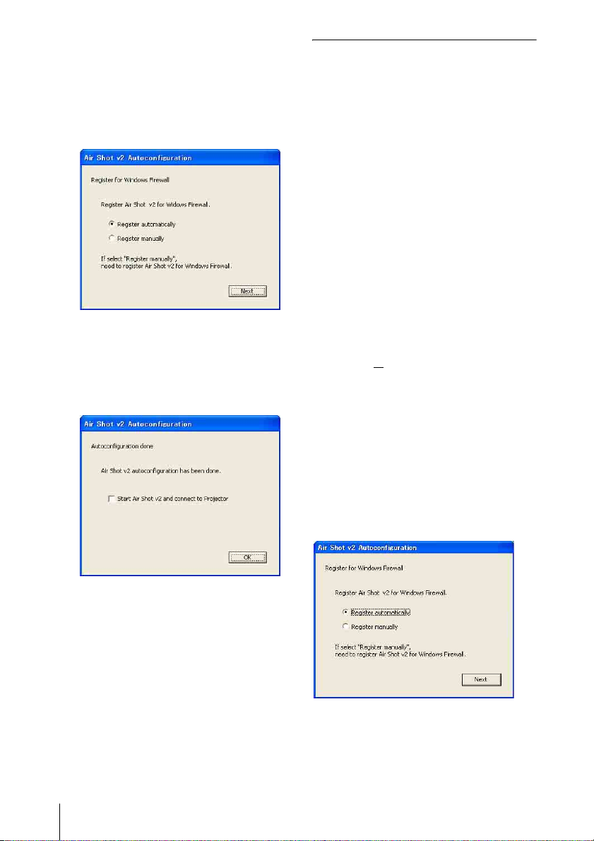
3 Install the software according to the
“wizard” within the installer.
When you use Windows XP Service
Pack 2/Vista and the following dialog
box appears during installation, check
the [Register automatically] radio button
and click [Next].
The [Autoconfiguration done] appears
after the installation is completed.
4 To go on projecting the pictures, check
the [Start Air Shot v2 and connect to
Projector] check box and click [OK].
Starting from the hard disk or
external memory without installing
Projector Station for Air Shot
Version 2 into the computer
1 Install the external memory (“Memory
Stick”, USB memory, etc.) into the
computer.
It is not necessary to copy it to the hard
disk.
2 Put the supplied CD-ROM into the
CD-ROM drive of the computer.
When the application software
installation window appears, press the
Exit button to exit it.
3 Open [My computer], then put the
cursor on [CD-ROM drive] and rightclick.
When the item list appears, select
[Open (O
)].
4 Copy the folder of [PjStation for Air
Shot v2] to the hard disk or external
memory.
5 Execute [AutoConfig.exe].
With the check, the Projector Station for
Air Shot Version 2 starts up
automatically.
When you are not going to project the
pictures, click [OK].
6
Preparation
When you use Windows XP SP2/Vista
If the following window appears in the
middle of the operation, check the [Register
automatically] radio button and click [Next].
[Autoconfiguration done] appears after the
installation is completed.
To continue projecting the pictures, check
the [Start Air Shot v2 and connect to
Projector] check box and click [OK].
Page 7

Preparing the Projector
Setting the projector
1 Connect the network cable to the
NETWORK connector of the
projector.
2 Turn on the projector.
Projector Station for Air Shot Version 2
starts up automatically.
When you are not going to project the
pictures, click [OK].
After executing [AutoConfig.exe], start up
the application with [PjstnASv2.exe].
When you change the computer, execute
[AutoConfig.exe].
3 Press the INPUT C or AIR SHOT key
on the remote commander.
The home display of the network
presentation appears.
Serial number
Model name
Nick name (only
Operations
guide
Icon
Icons representing network status:
being not connected
being connected
when specified)
Mode
IP address
Preparation
7
Page 8
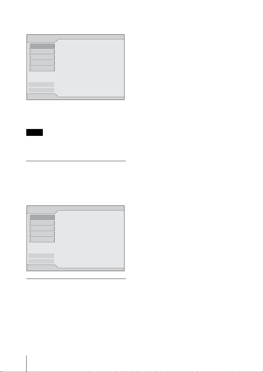
4 Press the ENTER key.
The setting menu display appears.
Network
Exit
Internet Protocol(IP)
IP Address Setting:
IP Address:
Subnet Mask:
Default Gateway:
Manual
192.168.11.21
255.255.255.0
192.168.11.253
Simple Mode
Manual Mode1
Manual Mode2
Manual Mode3
Manual Mode4
Manual Mode5
System Setup
5 Select [Setup] to set network setting
items.
2 Repeat step 1 to input characters.
3 After you input the rest of the
characters, select [OK] with v/V/B/
b button and press the ENTER key.
Input characters are entered and the
software keyboard is closed.
To delete the character locating one
space before the cursor
elect [Delete] with v/V/B/b button and
S
press the ENTER key.
To redo the input from the beginning
Select [All Clear] with v/V/B/ b button
and press the ENTER key.
All the input characters are deleted.
Note
To use the network function, set [Standby
Mode] in the Function menu of the projector to
[Standard].
Projector Setting Items
When the ENTER key is pressed in the home
display of the network presentation, the
initial display of the setting menu appears. In
the initial display, you can switch the mode
to be used and change each mode settings.
Network
Exit
Internet Protocol(IP)
IP Address Setting:
IP Address:
Subnet Mask:
Default Gateway:
Manual
192.168.11.21
255.255.255.0
192.168.11.253
Simple Mode
Manual Mode1
Manual Mode2
Manual Mode3
Manual Mode4
Manual Mode5
System Setup
Using the software keyboard
When inputting characters or numbers, the
software keyboard is displayed.
1 Select a character with the v/V/B/b
buttons and then press the ENTER
key.
The selected character is displayed at the
cursor position in the display column.
To enter a space
Select [Space] with v/V/B/b button and
press the ENTER key.
8
Preparation
Page 9
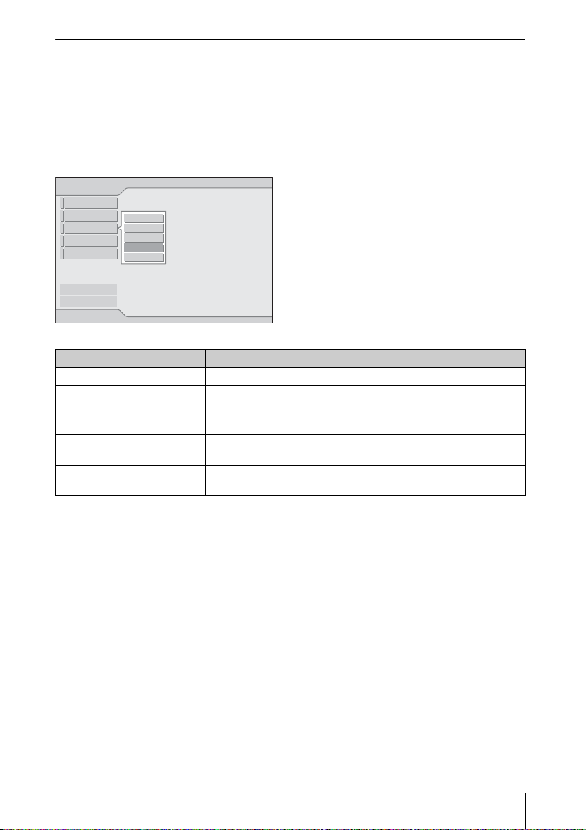
Setting each mode
In the initial display of the setting menu, the left edge of the mode currently used is displayed
in light blue. You can switch the mode to be used and change the mode name and settings.
x Displaying the setting items menu (action menu)
You can select the item with
V or v key and the selected item is highlighted. The status appears
in the right pane of the window.
Press the ENTER key to display the setting item menu (action menu).
Network
Exit
Internet Protocol(IP)
IP Address Setting:
Close
IP Address:
Select
Subnet Mask:
Status
Default Gateway:
Setup
Rename
Manual
192.168.11.21
255.255.255.0
192.168.11.253
Simple Mode
Manual Mode1
Manual Mode2
Manual Mode3
Manual Mode4
Manual Mode5
System Setup
Items Functions
Close Closes the action menu.
Select Sets the selected mode effective.
Status (only for the mode
Displays the status of the mode currently used.
being used)
Setup Displays the [Network Setting] window to change the mode
settings.
Rename Renames the mode. You can input the maximum of 16 characters/
numbers/symbols.
Preparation
9
Page 10

x Displaying the mode status
When you select [Status] from the action menu, the status of the mode being used is displayed.
Items Display contents
Internet Protocol(IP) Displays [IP Address Setting (Manual/Auto)], [IP Address],
PC Registration List Displays the address of the entered PC.
Close Closes the [Network Status] window.
[Subnet Mask], [Default Gateway], [Primary DNS], [Secondary
DNS], [DHCP Server], and [Lease Obtained]/[Lease Expires].
[Lease Obtained]/[Lease Expires] means the valid period of the IP
address assigned from the [DHCP Server] automatically.
x Changing the settings
When you select [Setup] from the action menu, the [Network Setting] window of the selected
mode is displayed, where [Internet Protocol(IP)] and [PC Registration List] settings can be
changed. Select the desired item and press the ENTER (or right) key to activate its setting items.
To input the desired value for the items, press the ENTER (or right) key. You can return to the
setting menu with the ENTER (or left) key. Click [OK] to save the settings and return to the
initial display of the setting menu. If you select [Cancel], the settings will not be saved and the
initial display of the setting menu appears.
Items Functions
Internet Protocol(IP) Specify the [Internet Protocol(IP)] settings: [IP Address
IP Address Setting Select [Auto(DHCP)] or [Manual].When the [Manual] is
IP Address Set the IP address for the projector.
Subnet Mask Set the subnet mask for the projector.
Default Gateway Set the default gateway for the projector.
Primary DNS Set the primary DNS server. (1.0.0.0~223.255.255.255)
Secondary DNS Set the secondary DNS server. (1.0.0.0~223.255.255.255)
PC Registration List Enter the IP address or the network address/broadcast IP
Setting (Manual/Auto)], [IP Address], [Subnet Mask],
[Default Gateway], [Primary DNS], [Secondary DNS].
selected, set [IP Address], [Subnet Mask] and [Default
Gateway].
(1.0.0.0~223.255.255.255)
(128.0.0.0~255.255.255.254)
(1.0.0.0 ~223.255.255.255)
address in the IP address box to connect a computer that has
a different network segment (subnet) from the projector.
When the network address/broadcast IP address is entered,
select the subnet mask from the list. Up to 10 IP and
network/broadcast IP address can be entered.
10
Preparation
Page 11

Setting the System Setup
When [System Setup] is selected in the initial display of the setting menu, the [System Setup]
window is displayed. Select the desired item and press the ENTER (or right) key to activate its
setting items. To input the desired value for the items, press the ENTER (or right) key. You can
return to the setting menu with the ENTER (or left) key. Click [OK] to save the settings and
return to the initial display of the setting menu. If you select [Cancel], the settings will not be
saved and the initial display of the setting menu appears.
Items Functions
Network Input the [Nickname], [Group Name] and [Password] for
Nickname Enter the nickname proper to the projector with the
Group Name Set this item to limit the connection.
Password Set this item to limit the connection.
Information Displays the version of each function.
the projector.
maximum of 24 characters/numbers/symbols.
Enter the group name who can connect to the projector with
the maximum of 8 characters/numbers/symbols.
Note
If you enter a different group name from that of [Group
Name] of [Profile Setting] tab in the application software of
the connected computer, the application software does not
display the Projector button.
Enter the password to connect to the projector with the
maximum of 32 characters/numbers/symbols.
Notes
• When you enter the Password, you need re-enter it for
confirmation.
• If you enter a different password from that of [Password]
of [Profile Setting] tab in the application software of the
connected computer, you cannot connect to the projector.
Preparation
11
Page 12

Connection
Connecting Examples
Connecting to wireless LAN using
the computer access point
LAN
Connecting to wired LAN
Projector
Computer
Computer
Computer
LAN
Notes
• For a LAN connection, contact your network
administrator.
• When the projector and a computer that has a
different network segment (subnet) are
connected, set [PC Registration List] (page
10) on the projector and [Projector Setting]
(page 18) on the computer.
Projector
Access point
Computer
Computer
Notes
• For a LAN connection, contact your network
administrator.
• When the projector and a computer that has a
different network segment (subnet) are
connected, set [PC Registration List] (page
10) on the projector and [Projector Setting]
(page 18) on the computer.
12
Connection
Page 13

Connecting to several projectors at
the same time
Projector*
Projector*
Projector*
Computer
LAN
Connecting/Disconnecting/ Switching from the Projector
Connecting
1 Turn on the power of the projector and
press the INPUT C or AIR SHOT key
on the remote commander.
The home display of the network
presentation appears.
2 Start the Projector Station for Air Shot
Ve r si o n 2 .
When it starts, the [ ] icon appears in
the task tray.
When [Create Shortcut Icon into Startup
Folder.] is selected at installation, the
Projector Station for Air Shot Version 2
starts automatically.
3 Right-click the [ ] icon in the task
tray and select [Open].
The main window of Projector Station
for Air Shot Version 2 opens.
* A maximum of 5 projectors can be
connected at the same time.
Notes
• To connect to LAN, contact your network
administrator.
• 5 projectors may not be able to be connected
at the same time due to the computer.
• When the projector and a computer that has a
different network segment (subnet) are
connected, set [PC Registration List] (page
10) on the projector and [Projector Setting]
(page 18) on the computer.
4 Press the AIR SHOT key on the
remote commander.
The list of the computer connected to the
projector appears.
5 Press the M or m key on the remote
commander to select the computer,
and then press the ENTER key.
When the connection confirmation
message appears in the computer,
click [Yes] to connect.
Connection
13
Page 14

Appears when the computer is connected.
Yamada PC
Tanaka PC ( xx. x. xx. xx )
Suzuki PC (xxx. xxx. xx. x)
Saito PC ( xx. x. xx. xx )
Sakuma PC (xxx. xxx. xx. x)
Yamada PC
Connecting PC: Tanaka PC
Notes
• When the projector and a computer that has a
different network segment (subnet) are
connected, set [PC Registration List] (page
10) on the projector and [Projector Setting]
(page 18) on the computer.
• A maximum of 100 computers can be
displayed in the list.
• It may take time to project an image due to
the computer.
• External monitor signal of notebook type
computer may not be output when you use
Projector Station for Air Shot Version 2.
• When [When a connection/Disconnection
request is received] is set to [Always Yes] or
[Always No] in the setting of the application
software, the connection confirmation
message does not appear and the application
software always permits/refuses connection/
disconnection.
• Do not change the resolution of the computer
desktop while the projector and the computer
are connected. They may become
disconnected.
(xxx. xxx. xx. x)
Disconnecting
1 Press the AIR SHOT key on the
remote commander.
2 Press the M or m key on the remote
commander to select the connecting
computer from the list, then press the
ENTER key.
When the confirmation message appears
in the computer, click [Yes] to
disconnect.
Switching
1 Press the AIR SHOT key on the
remote commander.
2 Press the M or m key on the remote
commander to select the computer to
be connected from the list and then the
ENTER key.
Connecting/Disconnecting/ Switching from the Computer
Connecting
1 Perform steps 1, 2 and 3 of
“Connecting” on page 13.
2 Click the projector button of the
projector to be connected.
Projector button
Notes
• When the projector and a computer that has a
different network segment (subnet) are
connected, set [PC Registration List] (page
10) on the projector and [Projector Setting]
(page 18) on the computer.
• It may take time to project an image due to
the computer.
• External monitor signal of notebook type
computer may not be output when you use
Projector Station for Air Shot Version 2.
Switching
Click the projector button being connected
on the main window and then select the
computer to be connected.
14
Connection
Page 15

Disconnecting
Click the projector button to disconnect the
project from the computer.
Names and Functions of the Main Window
When one projector is connected
When multiple projectors are
connected
IP address
Projector name
My PC
IP address
Computer name
Items Functions
1 [Refresh]
button
2 [Option
Setting] button
3 [Help]
button
4Scroll bar The scroll bar is displayed
5[PC List]
buttons
6[Tool bar
select] button
7 [
Minimum]
button
8 [Close]
button
9Projector
button
q;Controlled
projector select
menu
qa Connected
computer
display
The projector list, connected
computer list, and connectable
computer list are refreshed
manually.
The [Option Setting] window
for setting the Projector Station
for Air Shot Version 2 is
displayed. When the computer
is not connected to the
projector, you can display the
window.
Projector Station for Air Shot
Version 2 help topics will be
displayed.
when 6 or more projectors exist.
When the button is clicked,
the connectable computer list is
displayed.
When the button is clicked,
the list is closed.
When the button is clicked,
only the tool bar for the
projector control is displayed.
When the button is clicked,
the whole main window is
displayed.
The Projector Station for Air
Shot Version 2 main window is
reduced minimum.
The Projector Station for Air
Shot Version 2 main window is
closed.
The icon of the connectable
projector, projector name (or
Nickname, if specified) and IP
address are displayed on the
button. Click the button to
connect to or disconnect from
the projector. By right-clicking
on the button and selecting
[Show Projector Web], the Web
display of the projector appears
on the computer.
Select the projector to be
operated by the projector
control buttons. When only one
projector is connected, this
menu is not displayed.
The icon, computer name, and
IP address of the computer
being connected to the projector
are displayed. The computer
name is changed in the [Option
Setting] window.When no
computer is connected to the
projector, this display does not
appear.
Connection
15
Page 16

Items Functions
qsProjector
control buttons
With the buttons, you can
operate the projector selected
on the controlled projector
select menu.When only one
projector is connected, the
projector will be operated.
[Picture Muting] button: Click
the button to clear the picture
temporally. Click it again to
display the picture.
[Freeze] button: Click the
button to stop the motion of the
picture. Click it again to restart
the picture.
[Input Select] button: Click the
button to select the input signal.
[Power On/Standby] button:
Click to turn on the power of
the projector or set it in standby
mode.
Using the [Option Setting] Dialog Box
This is used for the settings of Projector
Station for Air Shot Version 2.
Displaying the setting window of
Projector Station for Air Shot
Version 2
Click the [] button in the main window
of Projector Station for Air Shot Version 2.
Names and Functions of the tabs
on the [Option Setting] dialog box
For the details, click the [ ] button on the
main window to display the online help.
[Basic Setting] tab
The [Basic Setting] tab provides the basic
setting items.
When the connectable projector cannot be
detected with the selected LAN module, the
connectable projector is being searched
according to the priorities of the LAN
modules.
When the network cable (RJ45) is not
connected to the computer, the search may
not be done automatically.
Note
[Use USB Wireless LAN Module as Simple
Mode] is not available for this unit.
Do not check the check box.
[Simple Mode Setting] tab
The [Option Setting] dialog box appears.
Note
When the computer is not connected to the
projector, the [Option Setting] dialog box is
opened.
16
Connection
This is not available for this unit.
Page 17

[Profile Setting] tab
[Connection Setting] tab
Note
When [Set PC desktop to Projector resolution]
is checked, the window may be shown outside
of the display due to the position of the window
of ProjectorStation for AirShot Version2.
The [Profile Setting] tab provides the profile
settings for connecting to the projector.
The [Connection Setting] tab provides
detailed settings for connecting to the
projector.
Connection
17
Page 18

[Projector Setting] tab
The IP address of the projector must be
specified when the projector has the
different network segment (subnet) from the
computer.
Up to 100 projectors can be entered.
[Others] tab
Setting/Operating via Web
You can check the information of the
projector from the computer or operate the
projector on the computer. Check the
connection and turn on the equipment.
Accessing from the Computer
You can access the Web page of the projector
by either of the following two ways.
Right-click the projector button in the main
window of Projector Station for Air Shot
Version 2 and click the displayed [Show
Projector Web].
Start a browser of the computer (Internet
Explorer 5.0 or higher) and enter the address
“http://xxx.xxx.xxx.xxx (IP address of the
projector)”.
The [Others] tab provides other settings.
To use the Simple Mode in this version of
Projector Station for Air Shot Version 2,
check the check box of [Enable Air Shot V2
Version 1.x transparent mode]. [Use USB
Wireless LAN Module as Simple Mode] of
the [Basic Setting] tab and the [Simple Mode
Setting] tab can be used.
Do not check when only the VPL-CX155/
CX125/CW125 series model is used.
18
Setting/Operating via Web
Note
If the browser of your computer is set to
“Access the Internet using a proxy server,”
enter the IP address of the projector in the box
“Access the Internet without using a proxy
server” when you have access to the projector
from your computer.
Page 19

After access, the following display appears.
Confirming the State of Projector Settings (Information)
Click [Information].
You can confirm the current state of the
projector on the computer. You cannot
change the settings of the projector.
Operating the Projector (Control)
Click [Control].
You can control the projector on the
computer. The functions of each button
provide the same functions the button of the
identical name.
Setting the Connecting Mode
Click [Network].
You can switch the mode and set each mode.
To switch the mode, select the desired mode
button and then click [Select].
To set each mode, select the desired mode
button and then click [Setup] to display the
Setup display of the mode.
Click the [Apply] button to reflect the
projector.
Setting/Operating via Web
19
Page 20

Setting Up the Projector
Click [Setup].
The Setup menu dialog box appears.
You can set the Owner information,
Password, Date and Time, Mail Report, etc.
Click [Apply] in the lower part of each
window to update the projector to the data
input in each window.
Owner information
This information is used for the Mail Report
function.
Owner
Enter owner information.
Projector
Enter the location of the projector.
Memo
Enter a memo, if required.
20
Setting/Operating via Web
Setting the Date and Time
This setting is required for the Regular
Report function.
Page 21

Time Zone
Select the region in which you are using the
projector.
Date/Time
Set the date and time (MM, DD, YY,
HH:MM).
Time Server
Enter the address of the time server when the
time is set by a timer server.
Setting passwords for
“Administrator” and “User”
You can set passwords for each
“Administrator” and “User.”
The name of the “Administrator” account is
preset to “root” at the factory. It cannot be
changed.
You can specify the transmission days and
times of e-mail messages (Regular report).
• Immediately report if any error occurs
with the projector (Error Report).
• Send warning e-mail messages when a
preset time for use of the projector lamp
has been reached (Lamp Reminder).
• Send warning e-mail messages when a
preset time for maintenance of the
projector has been reached (Maintenance
Reminder).
Notes
• When you change the password, input a new
password after deleting the Password
(*****) that was set.
• If you forget your password, consult with
qualified Sony personnel.
Settings for the Mail Report
function
You can do the following with the Mail
Report function.
• Periodically report the installation status
of the projector, owner information, etc.
x Report Timing field
Regular Report
A report on the present status of the
projector, installation status, etc. of the
projector is periodically sent by e-mail.
Set the timing for sending the e-mail
messages as follows:
AT: Specify the time when e-mail is to be
sent. Select the hour from the drop-down
list.
Every Week on Days: Select this check box
to send e-mail on the selected days every
week.
Setting/Operating via Web
21
Page 22

Mon/Tue/Wed/Thu/Fri/Sat/Sun: Specify
the days of the week when e-mail is to be
sent. You can check two or more days.
Every Month on Day: Select this check box
and select the day from the drop-down
list to send e-mail on a pre-defined day
every month. The Regular Report
contains the product information, owner
information, usage information (time)
for the projector, lamp mode, memos,
etc.
Maintenance Report
Lamp Reminder: Select this check box and
enter the limit for the number of hours
the projector lamp is to be used in the
text box. This information will be used
to send e-mail informing you that
replacement is required for the projector
lamp when the preset time has been
reached. You can specify a time between
1 and 9999 hours.
Maintenance Reminder: Select this check
box and enter the hours of use before
maintenance is required for the projector
in the text box. You can specify a time
between 1 and 99999 hours.
The elapsed time is displayed in the
Elapsed Hours text box. Selecting the
RESET and clicking “Apply” will reset
the elapsed time to zero.
x Address field
E-mail Address
Enter the e-mail addresses to which you
want the e-mail messages to be sent in each
text box. The projector allows you to send email to 4 different addresses. You can enter
up to 64 characters for each address.
Report Timing
Regular: Select this check box to arrange
the sending of the Regular Report.
Maintenance: Select this check box to
arrange the sending of an e-mail
message that informs you of the number
of hours the projector lamp has been
used and the time when maintenance is
required for the projector.
Error: Select this check box to arrange the
sending of an error report if any problem
occurs with the projector.
Notes
• Even if days are specified in the Report
Timing field, you still must select the
Regular check box to receive the Regular
Report. If the day preset in “Every Month on
Day” does not exist in the month, you will
receive the e-mail message on the last day of
the month.
• You cannot specify the day of the week or
day of the month if “Every Week on Days” or
“Every Month on Day” is not selected.
x Mail Form field
Select the e-mail message type from
“Standard” or “Simple.”
x Mail Account field
Mail Address
Type the appropriate e-mail address.
You can enter up to 64 characters.
Outgoing Mail Server (SMTP)
Type the address of the SMTP server.
You can enter up to 64 characters.
Requires Authentication
Select this check box when the
authentication is required for sending an
e-mail.
Requires the use of POP Authentication
before send e-mail (POP before
SMTP): Select this check box to arrange
for POP authentication to be performed
before connecting to the SMTP server.
Incoming Mail Server (POP3): Ty p e t he
address of the POP3 server.
Account Name: Type the mail account.
Password: Type the mail password.
SMTP Authentication: Select this check
box to arrange for SMTP Authentication
to be performed before connecting the
SMTP server.
Account Name: Type the mail account.
Password: Type the mail password.
Send test mail: Select the Send check box,
then click “Apply” to send an e-mail
message as a test to confirm whether it is
sent to the specified addresses.
22
Setting/Operating via Web
Page 23

Notes
• If the following items have not been set or are
incorrectly set, an error message appears and
the test e-mail message is disabled:
- Address in the Address field.
- “Mail Address” and “Outgoing Mail Server
(SMTP)” in the Mail Account field.
For details on the mail settings, consult your
network administrator.
• The mail report function is not available
because the network which Outbound Port25
Blocking is used cannot be connected to the
SMTP server.
x Check the contents of the mail
message
The contents of the e-mail message to be
sent appear.
Advanced setting
Click “Advanced Menu” to display the
Advertisement button, PJ Talk button,
SNMP button, PJ Link button and Service
button. These settings are mainly for
administrative use. For details, consult with
qualified Sony personnel.
Note
You cannot use the following characters to
enter the characters in the text box: “ ' ”, “ “ ”,
“ \ ”, “ & ”, “ < ”, “ > ”
Setting/Operating via Web
23
Page 24

Others
Troubleshooting
Symptom Cause and Remedy
The projector cannot be
detected.
The projector cannot be
connected.
The projector is disconnected
in midway.
The computer is not displayed
in the PC list. (Projector)
• If the Firewall is installed in the computer, communications
with the Projector Station for Air Shot Version 2 may be
blocked, which may cause an irregularity; the projector
cannot be detected or connected, or the projector is
disconnected in midway.
c Set the Firewall so that the following port numbers
Projector Station for Air Shot Version 2 uses will not be
blocked. For how to set the Firewall, see the manual of the
Firewall software you use.
Port numbers that Projector Station for Air Shot Version 2
uses:
- 51217 (TCP/UDP)
- 53125 (TCP/UDP).
Note
If you release the block carelessly, the computer becomes unguarded
and may be suffered by a dangerous virus attack. Consult with the
network administrator and pay special attention to firewall setting.
Allow the communication for only the necessary ports.
• The network segment (subnet) of the computer and the
projector are different.
c Set the PC Registration List (page 10) on the projector and
[Projector Setting] window (page 18) on the computer.
• The check box of [Use USB Wireless LAN Module as
Simple Mode] on [Option Setting], [Basic Setting] tab is
checked.
c This function is not used for this model. Remove the check.
• [Standby Mode] in the Function menu of the projector is not
set to [Standard].
c Set to [Standard].
• Projector Station for Air Shot Version 2 is not installed in the
computer nor started.
c Install it.
c Start Projector Station for Air Shot Version 2.
• The network cable is not connected to the projector.
c Connect the network cable to the NETWORK connector of
the projector.
• The network segment (subnet) of the computer and the
projector are different.
c Set the PC Registration List (page 10) on the projector and
[Projector Setting] window (page 18) on the computer.
• The network setting of the projector or computer is not set
correctly.
c Check that the network setting is the same as that of the
connected equipment.
24
Others
Page 25

Symptom Cause and Remedy
The computer and projector are
connected in the main window
of Projector Station for Air
Shot Version 2 but the image
cannot be projected on the
projector.
The image displayed on the
projector is different from that
of the computer.
The computer cannot access
the Web page of the projector.
The mouse pointer displayed
on the projector is different
from that of the computer.
• The projector is set to a picture muting.
c Press the PIC MUTING key on the remote commander to
release the muting.
• INPUT C is not selected on the projector.
c Press the AIR SHOT key on the remote commander or
select INPUT C using the INPUT button.
• The following application software or screen saver may not
be transported correctly.
– Application software that uses DirectX
– Application software that plays back a movie
– Microsoft Office assistant
– Microsoft IME tool bar
– Tool tip displayed by mouse over
– Full screen of MS DOS prompt
• [Set PC desktop to Projector resolution] in the [Option
Setting] - [Connection Setting] is unchecked and the image
of the computer is displayed in a higher resolution than the
XGA (VPL-CX125/CX155) /WXGA (VPL-CW125).
c An image on the projector is deteriorated when the
computer is set to a higher resolution than the XGA (VPLCX125/CX155) /WXGA (VPL-CW125).
• The projector is not displayed in the main window of
Projector Station for Air Shot Version 2.
c See “The computer is not displayed in the PC list.
(Projector)” on page 24.
• The browser of the computer is set to “Access the Internet
using a proxy server”.
c Set to “Access the Internet without using a proxy server”.
• The version of the browser is old or a browser other than
Internet Explorer is used.
c Use Internet Explorer version 5.0 or higher.
• [Track mouse shape] in the [Option Setting] - [Connection
Setting]-[Advanced] is not checked.
c Check [Track mouse shape].
When the computer is
connected to the projector, the
mouse moves more slowly.
Note
The shape of the mouse on the projector is displayed in black and
white.
• The computer is logged on with other than administrator
privileges (Windows Vista/XP/2000 only).
c The mouse moves slowly when the computer is logged on
with other than administrator privileges.
• In the [Option Setting]-[Connection Setting] -[Advanced],
[Capture image with video acceralator "off"] is not checked.
c Check [Capture image with video acceralator "off"].
c Even when the computer and OS of the recommended
system are used, the mouse may move slowly.
Others
25
Page 26

Messages on the Display
PC: Message displayed on the computer
PJ: Message displayed on the projector
Message PC PJ Cause and Remedy
Now searching LAN
Module.
Waiting until the IP
address is set.
No connectable Projector
has been found.
Network communication
error.
Projector communication
password error.
a
a
a
a
a
• The connectable LAN module within the PC is being
searched according to the priorities of the LAN modules
specified in the [Option Setting] window.
c If the message persists, check and set the LAN module
to be used in [Basic Setting] of the [Option Setting]
window.
• The Projector Station for Air Shot Version 2 is waiting
for the IP address to be set for the LAN module.
c If this message persists, check the wireless and network
settings for the LAN module you use. If the
Auto(DHCP) is selected, it may take few minutes to set
the IP address.
• The Projector Station for Air Shot Version 2
communications are blocked because of the Firewall.
c See the “Troubleshooting” on page 24.
• The network setting of the projector is not identical with
those of the computer.
c Check and re-set the network setting for both the
projector and computer.
• The network segment (subnet) of the computer and the
projector are different.
c Set the PC Registration List (page 10) on the projector
and [Projector Setting] window (page 18) on the
computer.
• Wireless transmission conditions are extremely poor
when the wireless network is used for the computer.
c Place the computer close to the access point, or remove
the obstacles between the access point and computer.
• Network conditions are poor.
c Contact your network administrator.
• The computer is unable to perform proper network
communications.
c Restart Windows and start Projector Station for Air
Shot Version 2.
c Check the setting of the USB wireless LAN module
used in the Projector Station for Air Shot Version 2.
• The password specified with the projector is not
identical with those specified with the computer.
c Set the same password to the computer as the projector
in the [Profile Setting] of the [Option Setting] dialog
box.
26
Others
Page 27

Message PC PJ Cause and Remedy
The Projector is busy.
Selected PC is busy.
Request for connection/
disconnection rejected.
Projector connection
established already.
Selected PC exceeds
maximum number of
connection.
Projector is stand-by. • The projector you are trying to communicate is in the
No response from
projector.
a
a
a
a
a
a
• The projector you are trying to communicate is
performing turning on/off operations.
c After the projector operations are complete,
communicate it and turn it off again.
• The [Setting] window of the projector is open.
c Close the [Setting] window and then communicate it
and turn it off again.
• The computer you are trying to communicate is
performing turning on/off operations.
c After the computer operations are complete,
communicate it and turn it off again.
• The [Option Setting] window is open.
c Close the [Option Setting] window and then
communicate it and turn it off again.
• The [Option Setting] -[Connection Setting] - [When
Connection/Disconnection request is received] is set to
[Always No].
c Set it either to [Display Confirm Dialog] or [Always
Ye s] .
• The computer cannot communicate with the projector as
the other computer has already established
communications with the projector.
c After the projector is disconnected from the computer,
communicate with the projector again.
• You tried to connect more than 5 projectors to one
computer.
c Reduce the number of the connected projectors to 4 or
less and then connect it again. (The maximum of 5
projectors can be connected to one computer.)
standby mode.
c Turn on the projector and then try communicating it.
• The Projector Station for Air Shot Version 2
communications are blocked because of the Firewall.
c Change the Firewall settings so that the Projector
Station for Air Shot Version 2 communications are not
blocked.
• Network conditions are poor.
c Contact your network administrator.
• The power cord of the projector is removed.
• The network cable is removed from the projector.
c Check the projector status.
• While connecting to the projector, the network cable is
removed from the projector or computer.
c Restart Windows and start the Projector Station for Air
Shot Version 2, and then connect the USB wireless
LAN module.
Others
27
Page 28

Message PC PJ Cause and Remedy
Unable to switch
resolution of PC desktop.
LAN Module with same
network address exists.
LAN Module
disconnected while
connecting.
System error/Quit
Projector Station for Air
Shot Version 2
The same IP Address
already exists.
Projector connection
error.
Projector connection
failure.
a
a
a
a
aa
a
a
• When the screen resolution of the computer is not
identical with the projector LCD panel resolution, and
when the computer is connected to the projector with
[Set PC desktop to Projector resolution] of the [Option
Setting]-[Connection Setting] checked, the resolution
switching of the computer cannot be done successfully.
c If the message appears every time the computer is
connected to the projector, uncheck [Set PC desktop to
Projector resolution].
• The IP address on the same subnet mask which is used
by the LAN module for the network has been assigned
to another LAN module.
c Check the IP Address Setting of the LAN module used
with the Projector Station for Air Shot Version 2 and
that used in the computer. Then change the settings so
that their network addresses are not identical.
• While the computer is connected to the projector, the
LAN module is removed.
c If the USB or LAN module of PCMCIA is removed
during connection, the computer may become unable to
establish proper connection with the projector. To
remove the USB or LAN module of PCMCIA, make
sure to disconnect the device.
• Because of the lack of system resources in the computer,
you cannot start the Projector Station for Air Shot
Version 2 properly.
c Restart Windows and start the Projector Station for Air
Shot Version 2.
• The set IP address is already in use.
c Input a new IP address.
• The network condition is not good.
c Consult a network administrator.
• When two or more projectors are connected, the image
cannot be projected because the resolution of the second
or subsequent projector is lower than that of the first.
c Connect the projectors in order of lower to higher
resolution.
28
Others
Page 29

Technical Terms
Default Gateway
This means a router address.
DHCP
The function to share the IP Address
automatically with the equipment connected
to the network. The DHCP server does not
share a fixed IP Address but shares the IP
Address with each equipment according to
the situation.
IP Address
The address to recognize each connected
machine in the TCP/IP network.
LAN (Local Area Network)
The network to be used in a limited area such
as an office or home.
MAC Address
The individual address to be shared at the
factory when it is produced.
There is no other machine with the same
address and the address cannot be changed
by the user.
Projector Station for Air Shot Version
2
The application software to use the network
presentation function. Install in the used
computer.
Subnet Mask
A means of allocating an IP Address
according to the individual need.
TCP/IP
The protocol to use in a network.
Each computer on the internet uses TCP/IP
to communicate with any other computer
and this is used as the protocol for LAN.
Others
29
Page 30

Sony Corporation
 Loading...