

Page 1

Data Projector
4-085-521-12 (2)
Operating Instructi ons
Mode d’emploi
Manual de instruccion es
VPL-CX11
GB
FR
ES
© 2001 Sony Corporation
Page 2

WARNING
To prevent fire or shock hazard, do
not expose the unit to rain or
moisture.
To avoid electrical shock, do not
open the cabinet. Refer servicing to
qualified personnel only.
This symbol is intended to
alert the user to the presence
of uninsulated “dangerous
voltage” within the
product’s enclo sure that may
be of sufficient magnitude to
constitute a risk of electric
shock to persons .
This symbol is intended to
alert the user to the presence
of important operating and
maintenance (servicing)
instructions in the literature
accompanying the
appliance.
For the customers in the USA
If you have any questions about this product,
you may contact:
Sony Electronics Inc.
Attn: Business Information Center (BIC)
12451 Gateway Boulevard
Ft. Myers, Florida 33913
Telephone No.: 800-686-7669
The number below is for FCC related
matters only.
Declaration of Conformity
Trade Name: SONY
Model No.: VPL-CX11
Responsible Part y: Sony Electronics Inc.
Address: 680 Kind erka mack Road, Orad ell,
NJ 07649 U.S.A.
Telephone No.: 201-930-6972
This device complies with Part 15 of the
FCC Rules. Operation is subject to the
following two conditions: (1) This device
may not cause harmful interference, and (2)
this device must accept an y interference
received, including interference that may
cause undesi re d operation.
This equipment has been tested and found to
comply with the limits for a Class B digital
device, pursuant to Part 15 of the FCC
Rules. These limits are designed to provide
reasonable protection against harmful
interference in a residential installation.
This equipment generat es, uses, and can
radiate radio frequency energy and, if not
installed and use d in accordance with the
instructions, may cause harmful interfe rence
to radio communications. However, there is
no guarantee that interference will not occ ur
in a particular installation. If this equ ipmen t
does cause harmful interference to radio or
television reception, which can be
determined by turning th e equipment off and
on, the user is encouraged to try to correct
the interference by one or more of the
following measure s :
- Reorient or relocate the receiving antenna.
- Increase the separation between the
equipment an d receiver.
- Connect the equipment into an outlet on a
circuit different from that to which the
receiver is connected.
- Consult the dealer or an experienced radio/
TV technician for help.
You are cautioned that any changes or
modifications not expressly approved in this
manual could vo id your authori ty to ope rate
this equipment.
GB
2
Page 3

For the customers in Canada
This Class B digital apparatus complies with
Canadian ICES-003
Voor de klanten in Nederland
Gooi de batterij niet weg
maar lever deze in als klein
chemisch afval (KCA).
The socket-outlet should be installed ne ar
the equipment and be easily accessible.
GB
3
Page 4

GB
4
Page 5

Table of Contents
Overview
Precautions ......................................... 6
Features .............................................. 7
Location and Function of Controls ...9
Front/Left Side .............................9
Rear/Right Side/Bottom ...............9
Control Panel ..............................11
Connector Panel .........................12
Remote Commander ...................13
Setting Up and Projecting
Installing the Projector .....................15
Connecting the Projector ..................16
Connecting with a Computer ......16
Connecting with a VCR or 15k
RGB/Component
Equipment ......................18
Selecting the Menu Language ..........20
Projecting .........................................22
Effective Tools for Your
Presentation .....................25
Maintenance
Maintenance .................................... 31
Replacing the Lamp ................... 31
Cleaning the Air Filter ............... 32
Troubleshooting ..............................33
Warning Messages .....................35
Caution Messages ...................... 35
Other
Installation Example ........................ 36
Notes on Installation ........................ 38
Unsuitable Installation ............... 38
Unsuitable Conditions ................ 38
Specifications .................................. 39
Index ...............................................45
GB
Adjustments and Settings
Using the Menu
Using the MENU .............................26
The PICTURE CTRL Menu ............27
The INPUT SETTING Menu ...........28
The SET SETTING Menu ...............30
GB
5
Page 6

Overview
B
Precautions
On safety
• Check that the operating voltage of your
unit is identical with the voltage of your
local power supply.
• Should any liquid or solid object fall into
the cabinet, unpl ug the unit an d ha v e it
checked by qualified personnel before
operating it further.
• Unplug the unit from the wall outlet i f it is
not to be used for sev e ral days.
• To disconnect the cord, pull it out by the
plug. Never pull the cord itself.
• The wall outlet should be ne ar the unit and
easily accessible.
• The unit is not disconnected to the AC
power source (mains) as long as it is
connected to the wall outlet , even if the
unit itself has been turned off.
• Do not look into the lens while t he lamp is
on.
• Do not place your hand or objects near the
ventilation holes. The air coming out is
hot.
• Be careful not to catch your fingers by the
adjuster when you lift up the projector. Do
not push hard on the top of the projector
with the adjuster out.
• Install the projector on the floor or ceilin g.
Any other installation causes a
mulfunction such as color irregu larity or
shortened lamp life.
• For ceiling installation, consult with
qualified Sony personnel.
On illum ination
• To obtain the best picture, the front of the
screen should not be exposed to direct
lighting or sunlight.
• Ceiling-mounted spot lighting is
recommended. Use a cover over
fluorescent lamps to avoid lowering the
contrast ratio.
• Cover any windows that face the screen
with opaque draperies.
• It is desirable to install the projector in a
room where floor and walls are not of
light-reflecting material. If the floor and
walls are of reflecting material, it is
recommended that the carpet and wall
paper be changed to a dark color.
On preventing internal heat buildup
After you turn off the power with the I / 1
key, do not disconnect the unit from the wall
outlet while the cooling fan is still running.
Caution
The projector is equipped with ven ti lation
holes (intake) and ven tilation holes
(exhaust). Do not block or place anything
near these holes, or internal heat build-up
may occur, causing picture degradation or
damage to the projector.
On cleaning
• To keep the cabinet looking new,
periodically clean it with a soft cloth.
Stubborn stains ma y be removed with a
cloth lightly dampened with a mild
detergent solution. Never use strong
solvents, such as thinner, benzene, or
abrasive cleansers, since these will
damage the cabinet.
• Avoid touching the lens. To remove dust
on the lens, use a sof t dry cloth. Do no t use
a damp cloth, dete rgent solution, or
thinner.
• Clean the filter at regular intervals.
On repacking
• Save the original shipping carton and
packing material; they will come in handy
if you ever have to ship your unit. For
maximum protection, repack your unit as
it was originally packed at th e factory.
On data projector
• The data projector is manufactured using
high-precision technology. You may,
however, see tiny black points and/or
bright points (red, blue, or green) that
continuously appear on the data projector.
This is a normal result of the
manufacturing process and does not
indicate a malfunction.
GB
6
Precautions
Page 7

Features
High p o rta bility
• Light weight/small size
This projector has been miniaturized to
approx. 3.3 kg (7 lb 4 oz) in weight and
A4-file size. A carrying handle is equipped
with the projector, so you can carry it
easily with your computer.
Reduced noise
Because the pr ojector uses a new cooling
mechanism, noise has been reduced.
High brightness, high picture
quality
• High brightness
Adopting the new developed optical
system and the 160 W lamp all ows high
brightness (light output 1500 ANSI
lumen) and excellent uniformity on the
picture.
• High resolution
Three 0.9-inch, about 790,000 pixel, XGA
panels provide a re s olu tio n o f 10 24 × 768
dots for RGB input and 750 ho rizontal TV
lines for video input.
Simp le s e tu p
• Simple setup with external equipment
This projector is preset for 37 kinds of
input signals. You can project images from
an external signal source just by
connecting the equipment with the
supplied cabl e an d pu s hin g the AP A key .
• Compatible with USB (Universal Serial
Bus) hub fu nction
You can connect an USB equipment (e.g.,
USB mouse) to the projector, and also
control the projector by using the
application software (CD-ROM) supp lie d
with the projector from a computer
operated with Windows 98, Windows 98
SE, Windows 2000 or Windows ME.
Using this application software, you can
open a file you want to use for your
presentation with the supplied Remote
Commander.
Easy presentation
• Multi functional Remote Commander
with mouse control functions
You can operate a computer connected to
this projector with the Remote
Commander since the unit has a build-in
mouse receiver.
• Digital ZOOM and FUNCTION keys
on the Remote Commander
The Digital ZOOM allows you to enhan ce
your presentation by zooming in on the
image. You can allocate a pr esentation file
to the FUNCTION keys by usi ng the
application software (CD-ROM) supplied
with the projector. Just pressing the
FUNCTION key opens the file
immediately.
Accepts various input signals
• Scan converter loaded
This projector has a build-in scan
converter that converts the input signal
within 1024 × 768 do ts.
• Compatible input signals
This projector accepts video signals of
composite, S video, and component as
well as 15k RGB, VGA, SVGA, XGA,
and SXGA signals, which all can be
displayed.
• Compatible with six color systems
NTSC, PAL, SECAM, NTSC
M, or PAL-N color system can be selected
automatically or manually.
4.43
1)
, PAL-
Overview
Features
GB
7
Page 8

......................................................................
.
• Windows is a registered trademark of
Microsoft Corporation in the United States
and/or other countries.
• VGA, SVGA, XGA, and SXGA are
registered trademarks of the Internat i onal
Business Machines Corporation, U.S.A.
• Macintosh is a registered trademark of
Apple Computer, Inc.
• IBM PC/AT is a registered trademark of
International Business Machines
Corporation, U.S.A.
• VESA is a registered trademark of Video
Electronics Standard Associ ation.
• Display Data Channel is a trademark of
Video Electronics St andard Association.
• PC-98 is a trademar k of NEC Corpor ation.
4.43
1)NTSC
is the color system used when
playing back a video r ecorded on NTSC
4.43
on a NTSC
system VCR.
GB
8
Features
Page 9
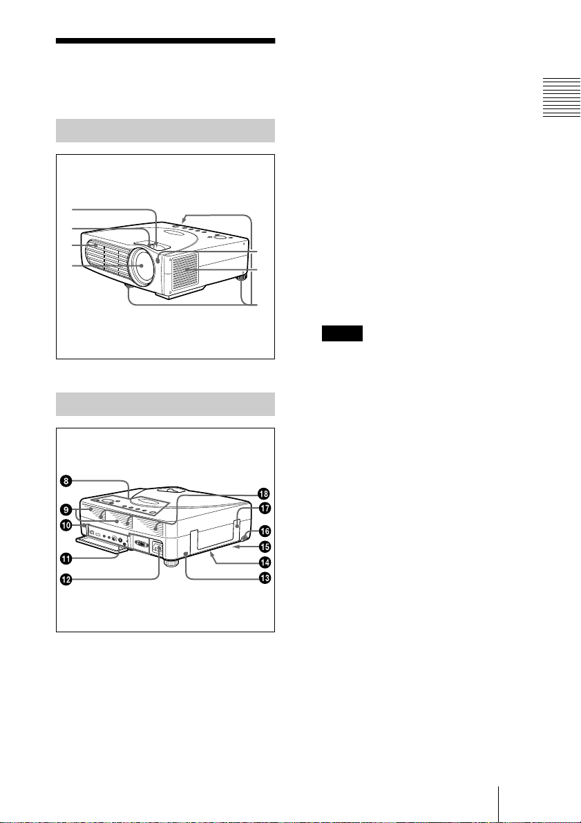
Location and
1 Zoom ring
Adjusts the picture size.
Function of Co ntrols
Front/Left Side
1
2
3
4
Rear/Rig h t Side /B o ttom
7
6
5
2 Focus ring
Adjusts the picture focus.
3 Ventilation holes (exhaust)
4 Lens
5 Adjuster
When a picture is projected on the
exterior of the s creen, adjust the pi cture
using this adjuster.
For details on how to use the adjusters,
see “How to use the adjuster” on page
10.
6 Ventilation holes (intake)/air
filter cover
Notes
• Do not place a n ythin g ne a r the
ventilat ion hole s as it m ay ca use inte rnal
heat build-up.
• Do not place your hand or objects near
the ventilation holes as it ma y cause t h e
air coming out heat build-up.
• To ma intain optim al per form ance, clean
the air filter every 300 h ou rs .
7 Front remote control detector
(SIRCS receiver)
Overview
8 Contro l pane l
For details, see “Control Panel” on
page 11.
9 Speakers
q;
q; Rear remote control detector
q;q;
(SIRCS receiver)
qa
qa Conn ec tor pa n el
qaqa
For details, see “Connector Panel” on
page 12.
qs
qs AC IN socket
qsqs
Connects the supplied AC power cord.
Location and Function of Controls
GB
9
Page 10

qd
qd Security lock
qdqd
Connects to an optional security cable
(Kensington’s).
The security lock corresponds to
Kensington’s MicroSaver
System.
If you require further information,
contact
Kensington
2855 Campus Drive
San Mateo, CA 94403
In North America
Phone: 800-235-6708
Fax: 800-247-1317
Outside North America
Phone: 847-541-9500
Home page address:
http://www.kensington.com/
qf
qf Ventillation h oles (intake,
qfqf
®
Security
bottom)
qg
qg Lamp cover (bottom)
qgqg
qh
qh RELEASE (adjuster adjustment)
qhqh
button
For details, see “How to use the
adjuster” on page 10.
How to use the adjuster
To adjust the height
Adjust the height of the projecto r as follows:
1
Lift the projector and press the
RELEASE bu tton.
The adjuster will extend from the
projector.
RELEASE button
2
While pr essing the b utton, lowe r the
projector. Then, release the button.
For fine adjustment, turn the adjusters to
the right and the left.
qj
qj Carrying handle
qjqj
Pull up the ha ndle fr om t he proj ector for
carrying.
qk
qk Ventilation holes (intake, rear)
qkqk
GB
Location and Function of Controls
10
to lower the
projector
Notes
• Do not rem ove the adjust ers f ro m the
projector. Do not use the pr ojec tor with the
adjusters remo ved.
• Be caref u l not to let the p rojector d own on
your fingers.
• Do not push hard on the top of the projector
with the a djusters out.
to ra ise the
projector
Page 11
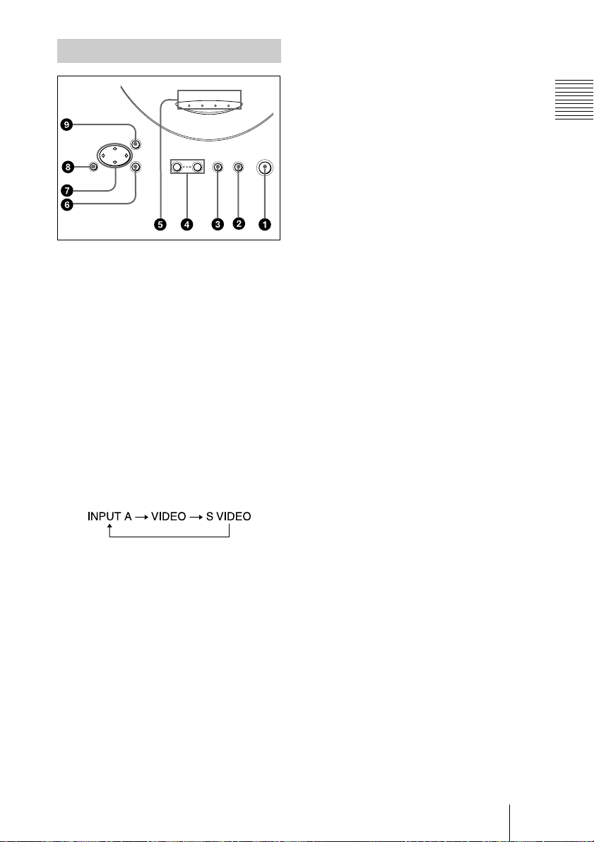
Control Panel
FAN/
POWER
LAMP/
COVER
MENU
RESET ENTER
– VOLUME +
1 I / 1111 (ON/STANDBY) key
Turns on and off the projector when the
projector is in standby mode. The ON/
STANDBY indicator lights in green
when the power is turned on.
When turning off the power, press
the I / 1 key t wice following the
message on the screen, or press and hold
the key for about one second.
For details on steps for turning off the
power, see “To turn off the power” on
page 24.
2 INPUT key
Selects the input signal. Each time you
press the key, the input signal switches
as follows:
3 APA (Auto Pixel Alignment) key
Adjusts a picture clearest automati cally
while a signal is input from a computer.
4 VOLUM E +/– keys
Adjust the volume of the built-in
speakers.
+ : Increases the volume.
– :
Decreases the volume.
ON/
TEMP
SAVING
STANDBY
APA INPUT ON/STANDBY
I / 1
5 Indicators
• LAMP/COVER: Lights up or flashes
under the following condition s:
– Lights up when the lamp has
reached the end of its life or
becomes a high temperature.
– Flashes when th e la mp cover or air
filter cover is not secured firmly.
• FAN/TEMP (Temperature): Lights
up or flashes under the following
conditions:
– Lights up when temperature inside
the projector becomes unusually
high.
– Flashes when the fan is broken.
• POWER SAVING: Lights up wh en
the projector is in power saving mode.
When POWER SAVING in the SET
SETTING menu is set to ON, the
projector goes in to power saving mod e
if no signal is input for 10 minutes.
Although the lamp goes out, the
cooling fan keeps run ning. In power
saving mode, any ke y does not
function for the first 30 seconds. The
power saving mode is canceled when a
signal is input or any key is pressed.
• ON/STANDBY: Lights up or flashes
under the following condition s:
– Lights in red when a AC power cord
is plugged into a wall outlet. On ce in
standby mode, you can turn on the
projector with the I / 1 key.
– Lights in green when the power is
turned on.
– Flashes in green while the cooling
fan runs after the power is turned off
with the I / 1 key. The fan runs for
about 60 seconds after the power is
turned off.
The ON/STANDBY indicator
flashes quickly for the first 30
seconds. During this time, you
cannot light up the ON/STANDBY
indicator with the I / 1 key.
For details on the LAMP/COVER and
the FAN/TEMP indicators, see page 35.
Overview
6 ENTER key
Enters the settings of items in the menu
system.
Location and Function of Controls
11
GB
Page 12

7 Arrow keys (MMMM/mmmm/<<<</,,,,)
Select the menu or to make various
adjustments.
8 RESET key
Resets the value of an item back to its
factory preset value. This key functions
when the menu or a setting item is
displayed on the screen.
9 MENU key
Displays the on-screen menu. Press
again to clear the menu.
Connector Panel
Rear side
CONTROL S
VIDEO IN INPUT A
IN / PLUG IN
POWER
1 INPUT A connector
Connect to external equipment such as a
computer.
• INPUT A connector (HD D-sub 15pin, female): Connects to the monito r
output on a computer using the
supplied cable.
When inputting a co mponent or 15k
RGB signal, use an optional cable.
For details, see “To connect a 15k RGB/
Component equi pme nt” on page 19.
• AUDIO (stereo minijack)
connector: Connects to the audio
output of the computer.
• MOUSE connector (6-pin):
Connects to the PS/2 mouse port on a
computer via the supplied mouse
cable, to control the mouse function of
the connected comput er.
INPUT A
2 VIDEO IN connector
Connect to external video equipment
such as a VCR.
• S VIDEO (mini DIN 4-pin):
Connects to the S video output (Y/C
video output) of video equipment.
• VIDEO (phono type): Connects to
the composite vi deo output of video
equipment.
• AUDIO (stereo minijack)
connector: Connects to the audi o
output of the VCR.
3 CONTRO L S IN/PLUG IN
POWER (DC 5V output) jack
Connects to the control S out jack of the
Sony equipmen t.
Connects to the CONTROL S OUT jack
on the supplied Remote Commander
when using it as a wired Remote
Commander. In this case, you do not
need to install the batteries in the
Remote Commander, since the power is
supplied from this jack.
4 USB connector (USB A-plug for
downstream, 4-pin)
Connect to USB equipment such as a
mouse, camera, etc.
5 USB connector (USB B-plug for
upstream, 4-pin)
Connect to the USB connector on a
computer.
When you connect the pro jector to the
computer, the projector recognizes the
mouse of the computer connected to the
INPUT A connector and you can control
the mouse function with the supplied
Remote Commander. The supplied
application software can be installed in
the comput er at tach e d t o t his co nne ct or.
GB
Location and Function of Controls
12
Page 13

Remote Commander
8
The keys that have the same names as those
on the control panel function identically.
You can control a connected computer using
the Remote Commander.
For details, see “To control the computer
using the supplied Re mot e Comm ander ” on
page 23.
+
VOLUME
–
RESET
(D ZOOM)
FUNCTION
I / 1
APA
R
CLICK
MUTING
PIC
INPUT
MENU ENTER
+
–
D ZOOM
12
6 R CLICK key
Functions as the right button on a mouse.
7 FUNCTION 1, 2 keys
These keys function when the supplied
application software is used.
When you connect the projector wi th a
computer, you can open a file on the
screen by just pressing the FUNCTION
key. This will enhance your
presentation. To use this function,
allocate a file to the FUNCTION key by
using the application software.
For details, see the README file and
the HELP file supplied with the
application software.
8 CONTROL S OUT jack (stereo
minijack)
Connects to the CONTROL S IN jack on
the projector with the connecting cable
(not supplied) when using the Remote
Commander as a wired one. In this case,
you do not need to install the batteries as
the power is supplied via the CONTROL
S IN jack on the projector.
9 RESET (D ZO O M ) key
Resets the value of an item back to its
factory preset value or returns the
enlarged image back to its original size.
Overview
1 I / 1111 key
2 APA (Auto Pixel Alignment) key
3 ENTER key
4 Joystick
Functions as the mouse of the computer
connected to the unit.
5 Arrow (
M/m/</,
) keys
0 D ZOOM +/–
key
Enlarges the image at a desired location
on the screen.
+: Pressing the + key on ce highlights
one of the images divi ded into 16.
Use an arrow key (M/m/</,) to
move the highlight portio n to the
point in the image to be enlarge d.
Press the + key repeatedly until the
image is enlarged to your
requirements.
–: Pressing the – key reduces an image
that has been enlarged with the D
ZOOM + key.
qa L CLICK key
Functions as the left button on a mouse.
qs MENU key
qd INPUT key
Location and Function of Controls
13
GB
Page 14

qf MUTING PIC key
Cut off the picture. Press again to restore
the picture.
qg VOLUME +/– keys
qh Infrared transmitter
To insta ll b a tt e rie s
1
Push and slide to open the lid, the n
install the two size AA ( R6) batteries
(supplied) with the correct pola rity .
Wh ile pr ess ing th e lid ,
slide it.
Be sure to install the
battery from the
side.
#
Notes on batteries
• Make sure that the battery orientation is
correct when inserting batteries.
• Do not mix an old batt ery with a new one
or different types of batteries.
• If you do not use the Rem ote C omm ande r
for a long time, remove the batteries to
avoid damage from battery leakage. If
batteries have leaked, remo ve them, wipe
and dry the battery co mpartment, and
replace the batteries with new ones.
Notes on Remote Commander
operation
• Make sure that nothing obstructs the
infrared beam between the Remote
Commander and the remote control
detector on the projector . Direct the
Remote Commander toward the front or
rear remote control detector.
• The operation range is limited. The shor ter
the distance between the Remote
Commander and the projector is, the wider
the angle within which the commander ca n
control the projector becomes.
2
Replace the lid.
GB
14
Location and Function of Controls
Page 15

Setting Up and Projecting
B
Installing the Projector
This section describes how to insta ll the projecto r.
The distance between the lens and the screen varies depending on the size of
the screen. Use the following table as a guide.
Distance between the screen and
the center of the lens
Unit: m (feet)
Screen size
(inches)
Minimum
Distance
Maximum
Distance
40 60 80 100 120 150 200 300
1.5
(4.8)
1.8
(5.8)
2.2
(7.3)
2.7
(8.8)
3.0
(9.8)
3.6
(11.8)
3.8
(12.4)
4.5
(14.8)
4.5
(14.9)
5.4
(17.8)
5.7
(18.6)
6.8
(22.3)
7.6
(24.9)
9.1
(29.8)
11.4
(37.5)
13.7
(44.9)
Setting Up and Projecting
For deta ils, see “Installation Exa mple” on page 36.
For deta ils on ceiling installation, consult with q ualified Son y personnel (fee
charged).
Installing the Projector
15
GB
Page 16

Connecting the Projector
To conn ect the pr ojector, refer to the illustrat ions on the n ext page
and the instructions below.
Notes
• Turn off all equipment before making any connections.
• Use the proper cables for each connection.
• Insert the cable plugs properly; plugs that are n o t f u lly inserted often
generate no ise. Whe n pulling o ut a cable, b e sure to p ull it out from the plug,
not the cable itself.
Connecting with a Computer
This section describes how to connect the projector to a computer.
For more information, refer to the computer’s instruction manu a l.
Notes
• The projector accepts VGA, SVGA, XGA, and SXGA signals. However, we
recommend that you set the output mode of your computer to XGA mode for the
external monito r.
• If you set your computer, such as a notebook type, to output the signal to both your
computer’s display and the external monitor, the picture of the external monitor may
not app ear properly. S et your c ompu ter to ou tput the signal to o nly the externa l
monito r.
For de tails, refer to the o peratin g in structio ns supplied wi th your comp uter.
• Supplied mouse cable may not work properly according to your computer.
• This pr o j e ctor is compa tible wit h a DDC2B ( Digital Data Channel 2B). I f y our
compu ter i s co m pat ible w ith a D DC , tu rn t he p ro jecto r on a ccor din g to the foll ow ing
procedures.
1 Connect the projector to the comp uter by using the supplied H D D-sub 1 5 pin cable.
2 Turn the projector on.
3 Start the computer.
GB
Connecting the Projector
16
Page 17

To connect an IBM PC/AT compatible computer
When you use a USB mouse and USB equipment
Rear side
INPUT A
CONTROL S
VIDEO IN INPUT A
IN / PLUG IN
POWER
to USB equipment
USB cable A type – B type (supplied)
On the USB function
When connecting the projector to a computer by using the USB cable for the
first time, the c ompute r r ec ognizes the f ollowing devices au tomatically.
1 USB hub (general use)
2 USB human interface device (wireless mouse function)
3 USB human interface device (projector control function)
The computer also recognizes the device connected to the downstream
connector on the projector.
Recommended operating environment
When y ou use the U S B fun c tion , conn e ct you r com p ute r as illu strate d a bo ve.
This application software and the USB function can be used on a co m puter
loaded with Windows 98, Window s 98 SE, Windo ws 2000 or Windows ME
preinstall m odels.
HD D-sub
15-pin cable
(supplied)
Stereo audio connecting
cable (not supplied)
to monitor output
to audio output
to USB connector
Computer
Setting Up and Projecting
Notes
• As the projector recognizes the USB mouse when the computer is
connected to the USB connector, do not connect anything to the PS/2
mouse port.
• Your computer may not start correctly when connected to the projector
via the USB cable. In this case, disconnect the USB cable, restart the
computer, then connect the computer to the projector using the USB
cable.
• This projector is not guaranteed for suspend, standby mode. When you
use the projector in suspend, standby mode, disconnect the projector
from the USB port on the computer.
• Operations are not guaranteed for all the recommended computer
environments.
Connecting the Projector
17
GB
Page 18

Rear side
When you use a PS/2 mouse port
INPUT A
CONTROL S
VIDEO IN INPUT A
IN / PLUG IN
POWER
HD D-sub
15-pin cable
(supplied)
Stereo audio connecting cable
(not supplied)
PS/2 Mouse cable
(supplied)
to monitor output
to audio output
to mouse port
(PS/2)
To connect a Macintosh computer
To connect a Macintosh computer equipped with video output connector of a
type having two rows of pins, use a commercially available plug adaptor. In
this case, however, you can not control the mouse of the com p uter by the
Remote Commander.
Connecting with a VCR or 15k RGB/Component Equipment
This section describes how to connect the projector to a VCR or 15k RGB /
component equipment.
For more in f or mation, refe r to the instructio n manuals of the equip ment you
are connecting.
Computer
To connect a VCR
Rear side
CONTROL S
IN / PLUG IN
POWER
GB
Connecting the Projector
18
VIDEO IN INPUT A
AV cable (supplied)
S-Video cable (not supplied)
to S video
INPUT A
output
audio
output
(R/L)
to
to video
output
VCR
Page 19

To connect a 15k RGB/Component equipment
Stereo audio connecting cable (not supplied)
SMF-402 Signal Cable (not supplied)
HD D-sub 15-pin (male) ↔ 3 × phono jack
Rear side
to RGB/
component
output
INPUT A
CONTROL S
VIDEO IN INPUT A
IN / PLUG IN
POWER
15k RGB/Componen t equipment
Notes
et the aspect ratio using ASPECT in the INPUT SETTING menu
• S
according to the input signal.
you connect the unit to 15k RGB/component video equipment,
• When
select RGB or component with the INPUT-A setting in the SET
SETTING menu.
se the composite sync signal when you input the external sync signal
• U
from 15k RGB/component equipment.
to audio
output
Setting Up and Projecting
Connecting the Projector
19
GB
Page 20

Selecting the Menu Language
You can select one of seven languages for displaying the menu and other onscreen displays. The factory setting is English.
1
3
LAMP/
COVER
Front remote control
detector
MENU
FAN/
POWER
ON/
TEMP
SAVING
STANDBY
APA INPUT ON/STANDBY
+
VOLUME
–
I / 1
APA
MUTING
PIC
INPUT
MENU ENTER
RESET ENTER
2
3
– VOLUME +
4,5,6
4,5,6
4,5,6
RESET
+
1
Plug the A C p ow er c ord o n the rear side on the p rojec tor into a w all ou tlet.
2
Press the I / 1 key to turn on the projector.
3
Press the MENU key.
The menu appears.
The menu presently selected is shown as a yellow button.
PICTURE CTRL
R
CLICK
CONTRAST:
BRIGHT:
GAMMA MODE: GRAPHICS
COLOR TEMP: HIGH
80
50
INPUT-A
I / 1
2
GB
Selecting the Menu Language
20
Page 21

4
Press the M or m key to sele ct the SET S ET TIN G m enu, th en p ress the ,
or ENTER key.
The selected menu appears.
SET SETTING
STATUS: ON
INPUT-A: RGB
KEYSTONE MEMORY:
DIGITAL KEYSTONE:
LANGUAGE: ENGLISH
INSTALLATION:
POWER SAVING
SIRCS RECEIVER:
LAMP TIMER:
5
Press the M or m key to select “LANGUAGE,” then press the , or
ON
OFF
FLR-FRONT
: OFF
FRONT&REAR
00010h
INPUT-A
ENTER key.
SET SETTING
STATUS: ON
INPUT-A: RGB
KEYSTONE MEMORY:
DIGITAL KEYSTONE:
LANGUAGE: ENGLISH
INSTALLATION:
POWER SAVING
SIRCS RECEIVER:
LAMP TIMER:
6
Press the M or m k ey to select a language, then press the < or ENTER
ON
OFF
FLR-FRONT
: OFF
FRONT&REAR
00010h
INPUT-A
key.
The menu changes to the selected language.
Setting Up and Projecting
To clear the menu
Press the M E NU key.
The me n u disappea rs a utomatically if a key is not pressed for one minute.
Selecting the Menu Language
21
GB
Page 22

Projecting
5
6
Rear re mote co n t ro l
detector
LAMP/
COVER
FAN/
TEMP
ON/ST AN D BY indicator
POWER
ON/
SAVING
STANDBY
1
MENU
RESET
MUTING
PIC
INPUT
MENU ENTER
1
I / 1
+
VOLUME
APA
–
Plug the A C pow er cord on th e rear s ide on the p rojector into a w all ou tlet,
ENTER
2
4
– VOLUME +
then connect all equipment.
The ON/STANDBY indicator lights in red and the projector goes into
standby mode.
2
Press the I / 1 key.
The ON/STANDBY indicator lights in green.
3
Turn on the equipment connected to the projector.
4
Press the INPUT key to select the input source.
To input from Press INPUT to display
Computer connected to the INPUT A connector INPUT A
Video equipment connected to the VIDEO input
connector
Video equipment connected to the S VIDEO input
connector
APA INPUT ON/STANDBY
I / 1
APA key
VOLUME +/–
keys
VIDEO
S VIDEO
4
2
GB
22
Projecting
Page 23

5
Turn the zoom ring to adjust the size of the picture.
6
Turn the f o c us ring to ad ju s t th e f ocus.
Caution
Looking into the lens when projecting may cause injury to your eyes.
To adjust the volume
Press VOLU M E +/– keys. The volume can b e adjusted for each of IN PU T A ,
VIDEO and S VIDEO input.
To cutoff the picture
Press the MUTING PIC key on the Remote Commander.
To restore the picture, press the MUTING PIC key again.
To control the computer using the supplied Remote Commander
When you connect an IBM PC/AT com patible to the projector, you can control
the mouse of the computer using the Rem ote Commander.
The R/L CLICK keys a nd joystick fu n c tion as follows.
Key and jo ys tic k Functio n
R CLICK (front) Right button
L CLICK (rear) Left button
Joystick Corresponds with the movements of the mouse
Note
Make sur e th a t no th ing ob s tru cts th e in fra red be am betw e en the R e m o te C o mman de r
and the remote control detector on the projector.
Setting Up and Projecting
To get the clearest picture
You ca n a d ju s t picture qua lity when p r oj e c ting a signal from th e c o mputer.
1
Project a s till p ic ture from th e c omputer .
2
Press the APA key.
“Com plete!” appears on the screen w hen the picture is adjusted properly.
Notes
• Press the APA key when the full image is displayed on the screen. If there are black
edges a r ound the image, the APA functio n will not functio n properly and the ima ge
may extend beyond the screen.
• When you switch the input signal or re-connect a computer, press the APA key again
to adjust the picture again.
• You can cancel the adjustment by pressing the APA key again while “ADJUSTING”
appears on the screen.
• The picture may not be adjusted properly depending on the kinds of input signals.
• Adjus t the item s in the I NPUT SETT ING menu when you adju st the pi cture m anuall y.
Projecting
23
GB
Page 24

To turn off the p ower
1
Press the I / 1 key.
“POWER OFF? Ple ase press I / 1 key again.” appears to confirm that you
want to turn off the power.
Note
A message disappears if you press any key except the I / 1 ke y, or if y ou d o no t
press any key for five seconds.
2
Press the I / 1 key again.
The ON/STANDBY indicator flashes in green and the fan continues to run for
about 60 seconds to reduce the internal heat. Also, the ON/STANDBY
indicator flashe s quickl y for the first 30 seconds . During this tim e, you will not
be able to light up the ON/STANDBY indicator with the I / 1 key.
3
Unplug th e AC pow er cor d from th e w all outlet afte r the fan stops run ning
and the ON/STANDB Y indicato r lig h ts in re d.
When you cannot confirm the on-screen message
When you cannot confirm the on-screen m essage in a certain condit ion, you can
turn off the power by holding the I / 1 key for abo ut on e s ec o nd.
Note
Do not un pl ug th e A C p o w er co rd w h ile the f an is still r un n in g; oth e rw is e, th e f an w ill
stop even though the internal heat is still high, which could result in a breakdown of the
projector.
GB
24
On air filter
To main tain optim a l p e r fo r mance, clean the air filter every 300 hours.
Projecting
Page 25

Effective Tools for Your Presentation
To enlarge the image (Digital Zoom function)
You can select a point in the image to enlarge.
1
Project the original size picture and press the D ZOOM + key on the
Remote Commander.
One of images divided into 16 is highlighted at the center of the image.
2
Move th e highlight po rtion to the poin t you want to enlarge by pre ssing the
arrow keys (M/m/</,).
3
Press the D ZOOM + key again.
The highlight portion displayed in step 2 is enlarged. By pressing the + key
repeatedly, the image size increases. (ratio of enlargement: max. 4 ti mes)
Setting Up and Projecting
Use the arrow keys (
To return the image back to its original size
Press the D ZOOM – key on the Remote Co m mander. Just pressing the
RESE T (ZOO M) key retu r ns the imag e back to its or ig inal size immediately.
M/m/</,
) to scroll the enlarged image.
Projecting
25
GB
Page 26

Adjustments and Settings Using the Menu
B
• When changing the adjust ment level:
Using the MENU
To increase the number, press the
, key.
To decrease the number, press the m
The projector is equipped with an on-screen
menu for making various adjustments and
settings. You can change the menu language
displayed in the on-screen menu.
To change the menu langu age, see
“Selecting the Menu Language” on page 20.
1
Press the MENU key.
The menu appears.
The menu presently selected is shown as
a yellow button.
PICTURE CTRL
CONTRAST:
BRIGHT:
GAMMA MODE: GRAPHICS
COLOR TEMP: HIGH
INPUT-A
80
50
or < key.
Press the ENTER key to restore the
original screen.
• When changing the setti ng:
Press the M or m key to change the
setting.
Press the ENTER or < key to restore
the original screen.
To clear the menu
Press the MENU key.
The menu disappears automatically if a key
is not pressed for one mi nute.
To reset items that have been
adjusted
Press the RESET key.
“Complete!” appears on the screen and the
settings appearing on the screen are reset
to their factory preset values.
Items that can be reset are:
2
Use the M or m key to select a menu,
then press the , or ENTER key.
The selected menu appears.
Menus
Setting items
•“CONTRAST,” “BRIGHT,” “COLOR,”
“HUE,” and “SHARP” in the PICTURE
CTRL menu
•“DOT PHASE,” “SIZE,” and “SHIFT” in
the INPUT SETTING menu
•“DIGITAL KEYSTONE” in the SET
SETTING menu
SET SETTING
STATUS: ON
INPUT-A: RGB
KEYSTONE MEMORY:
DIGITAL KEYSTONE:
LANGUAGE: ENGLISH
INSTALLATION:
POWER SAVING
SIRCS RECEIVER:
LAMP TIMER: 000
ON
OFF
FLR-FRONT
: OFF
FRONT&REAR
INPUT-A
About the memory of the settings
The settings are automatically stored in the
projector memory.
10h
If no sign a l is input
If there is no input signal, “NO INPUT–
Cannot adjust this item.” appears on the
screen.
3
Select an item .
Use the M or m key to selec t the item ,
then press the , or ENTER key.
or
M
4
Make the setting or a d justment on an
item.
GB
Using the MENU
26
Page 27

The PICTURE CTRL
Menu
COLOR
Adjusts color intensity. The higher the
setting, the greater the intensity. The lower
the setting, the lower the intensity.
The PICTURE CTRL (control) menu is used
for adjusting the picture.
Items that cannot be adjusted depending on
the input signal are not displayed in the
menu.
For details on th e unadjustable items, see
page 42.
When the video signal is input
PICTURE CTRL
CONTRAST:
BRIGHT:
COLOR:
HUE:
SHARP:
D. PICTURE:
COLOR TEMP:
COLOR SYS:
80
50
50
50
50
OFF
LOW
AUTO
VIDEO
When the RGB signal is input
PICTURE CTRL
CONTRAST:
BRIGHT:
GAMMA MODE: GRAPHICS
COLOR TEMP: HIGH
INPUT-A
80
50
HUE
Adjusts color tones. The higher the setting,
the picture becomes greenish. The lower the
setting, the picture becomes purplish.
SHARP
Adjusts the picture sharpness. The higher the
setting, the sharper the picture. The lower
the setting, the softer the picture.
D. (Dynamic) PICTURE
Emphasizes the black color.
ON: Emphasizes the black color to produce
a bolder “dynamic” picture.
OFF: Reproduces the dark portions of the
picture accurately, in acc ordance with
the source signal.
GAMMA MODE
Selects a gamma correction curve.
GRAPHICS: Improves the reproduction of
halftones. Photos can be reproduced in
natural to nes.
TEXT: Contrasts black and white. Suitable
for images that contain lots of tex t.
Adjustments and Settings Using the Menu
Menu Items
CONTRAST
Adjusts the picture contrast. Th e hi gher the
setting, the greater the contrast. The lo wer
the setting, the lower the contrast.
BRIGHT
Adjusts the picture brightness. The higher
the setting, the brighter the picture. The
lower the setting, the darker the picture.
COLOR TEMP
Adjusts the color temperature.
HIGH: Makes the white color bluish.
LOW: Makes the white color reddish.
COLOR SYS (System)
Selects the color system of the input signal.
• AUTO: NTSC
NTSC
• PAL-M/N: PAL-M/PAL-N and NTSC
(switched automatically)
Normally, set to AUTO. If the picture is
distorted or colorless, select the color system
according to the input signal.
3.58
4.43
, PAL, SECAM and
(switched automatically)
The PICTURE CTRL Menu
3.58
27
GB
Page 28

The INPUT SETTING
Menu
The INPUT SETTING menu is used to
adjust the input signal.
Items that cannot be ad justed depending on
the input signal are not displayed in the
menu.
For details on the unadjustable items, see
page 42.
When the video signal is input
INPUT SETTING
ASPECT:
4:3
When the RG B sign a l is input
INPUT SETTING
DOT PHASE:
SIZE H
SHIFT H
SCAN CONV: ON
15
800
H:200 V:30
MENU Items
DOT PHASE
Adjusts the dot phase of the LCD panel and
the signal input from the INPUT A
connector.
Adjust the picture further for finer picture
after the picture is adjusted by pressing the
APA key.
Adjust the picture to where it looks clearest.
VIDEO
No. 01
VIDEO/60
INPUT-A
No. 13
640 480
Memory
No.
Signal
type
Memory
No.
Signal
type
SIZE
Adjusts the horizontal size of picture input
from the INPUT A connector. The higher
the setting, the larger the horizontal size of
the picture. The lower the setting, the
smaller the horizontal size of the pict ure.
Adjust the setting according to the dots of
the input signal.
For details on the suitable value for the
preset signals, see page 43.
SHIFT
Adjusts the position of the picture input from
the INPUT A connector. H adjusts the
horizontal position of the picture.V adjusts
the vertical position of the picture. As the
setting for H increases, the pictur e moves to
the right, and as the setting decreases, the
picture moves to the left.
As the setting for V increases, the picture
moves up, and as the setting decreases, the
picture moves down. Use the < or the ,
key to adjust the hori zontal position and th e
M and m key for the vertical position.
SCAN CONV (Scan converter)
Converts the signal to display the picture
according to the screen size.
ON: Displays the picture according to the
screen size. The picture will lose some
clarity.
OFF: Displays the picture while matching
one pixel of input pi cture eleme nt to that
of the LCD. The picture will be clear but
the picture size will be small er.
Note
This item will not be displayed when XGA or
SXGA signal is input.
GB
The INPUT SETTING Menu
28
Page 29

ASPECT
Sets the aspect ratio of the picture. When
inputting 16:9 (squeezed) signal from
equipment such as a DVD player, set to
16:9.
4:3: W hen th e pic ture with rati o 4:3 is input.
16:9: When the picture with ratio 16:9
(squeezed) is input.
About the Preset Memory No.
Signal Memory No. SIZE
Super Mac-2 23 1312
SGI-1 23 1320
Macintosh 19" 25 1328
Macintosh 21" 27 1456
Sony News 36 1708
PC-9821
1280 × 1024
WS Sunmicro 37 1664
36 1600
This projector has 37 types of preset data for
input signals for INPUT-A (the preset
memory). When a preset signal is input, the
projector automatical ly detects the signal
type and recalls the data for the signal from
the preset memory to adjust it to an optimum
picture. The memory number and signal type
of that signal are displa ye d in the INP U T
SETTING menu. You can also adjust th e
preset data through the INPUT SETTING
menu.
This projector has 20 types of user memories
for INPUT-A into which you can save the
setting of the adjusted data for an unpreset
input signal.
When an unpreset signal is input for the first
time, a memory num ber is displayed as 00.
When you adjust th e data of the signal in the
INPUT SETTING menu, it will be
registered to the projector. If more than 20
user memories are registered, the newest
memory always overwr ites the oldest one.
See the chat on page 43 to find if the signal
is registered to the preset memory.
Since the data is recalled from the preset
memory about the following signals, you
can use these preset data by adjustin g SIZE.
Make fine adjustment by adjusting SHIFT.
Note
When the aspect ratio of input signal is other
than 4:3, a part of the screen is displayed in
black.
Adjustments and Settings Using the Menu
The INPUT SETTING Menu
29
GB
Page 30

The SET SETTING
Menu
The SET SETTING menu is used for
changing the settings of the projector.
SET SETTING
STATUS: ON
INPUT-A: RGB
KEYSTONE MEMORY:
DIGITAL KEYSTONE:
LANGUAGE: ENGLISH
INSTALLATION:
POWER SAVING
SIRCS RECEIVER:
LAMP TIMER: 000
ON
OFF
FLR-FRONT
: OFF
FRONT&REAR
Menu Ite m s
STATUS (on-screen display)
Sets up the on-screen display.
ON: Shows all of the on-screen displays.
OFF: Turns off the on-screen displays
except for the menus, a message when
turning off the power, and warning
messages.
INPUT-A
10h
When the downside of the trapezoid is
longer than the upside : Sets to a
minus value.
When the upside of the trapezoid is longer
than the downside : Sets to a plus
value.
LANGUAGE
Selects the languag e used in the menu and
on-screen disp lays. Availabl e languages a re:
English, French, German, Italian, Spanish,
Japanese and Chinese.
INSTALLATION
Sets to reverse the picture horizonta lly or
vertically.
FLR-FRONT: The picture is not reversed.
CEIL.-FRT: The picture is reversed
horizontally and vertically.
FLOOR-REAR: The picture is reversed
horizontally.
CEIL.-REAR: The picture is reversed
vertically.
Note
In case of using a mirror, be careful of
installation since the pictu re may be reve rsed.
INPUT-A
Selects th e RGB or component sign al input
from the INPUT A connector.
Note
If the setting is n o t correct, “Please check
INPU T -A settin g.” appears on the screen and
the color of the picture becomes strange or the
picture is not displayed.
KEYSTONE MEMORY
Memorizes the data adjusted with DIGITAL
KEYSTONE.
DIGITAL KEYSTONE
Adjusts trapezoidal distortion of the picture
that may occur depending on the projection
angle.
GB
The SET SETTING Menu
30
POWER SAVING
When set to ON, the projector goes into
power saving mode if no signal is input for
10 minutes.
SIRCS RECEIVER
Selects the remote control detectors (SIRCS
receiver) on the front and rear of the
projector.
FRONT & REAR: Activates both the front
and rear detector s .
FRONT: Activates the front detector only.
REAR: Activates the rear detector only.
LAMP TIMER
Indicates the total number of hours for which
the lamp currently used has been operated.
Page 31

Maintenance
B
Maintenance
Note
For safety sake, do not loosen any other
screws.
Replacing the Lamp
When the lamp has burnt out or dims, or
“Please replace the lamp. ” appears on the
screen, replace the lamp with a new one.
Use LMP-C160 Projector Lamp. The lamp
life varies depend ing on conditions of use.
When replacing the lamp after using
the proj ector
Turn off the projector, then unplug the
power cord.
Wait for at least an hour for the lamp to cool.
Caution
The lamp becomes a high temperature after
turning off the p r o j e ctor wit h the I / 1 ke y. If
you touch the lamp, you ma y scald your finger.
When you replace the lamp, wait for at least an
hour for the lamp to cool.
1
Place a protective sheet (cloth)
beneath the projector. Turn the
projector over so you can see its
underside.
Note
Be sure that the projecto r is stable af ter
turning it over.
2
Open the lamp cover by loosening a
screw w ith the Phillips sc r ewdriver
(supplied with the p ro je c t or la mp).
3
Loosen th e sc r e w on the lamp unit
with the Ph illips screw driver. P ull out
the lamp unit by the handle .
Handle
1
3
2
4
Insert the ne w lamp a ll the way in until
it is securely in place. T i g h te n the
screw. Fold up the handle.
2
1
3
Maintenance
Notes
• Be care fu l n ot to tou c h th e gla ss su rf ac e
of the lamp.
• The po wer will n ot turn on if the lam p is
not secured properly.
5
Close the lamp cover and tighten the
screws.
Maintenance
31
GB
Page 32

6
Turn the projector back over.
7
Connect the power cord and turn the
projector to standby mode.
8
Press the following keys on th e
control panel in the following or d e r
for less than five seconds each:
RESET, <, ,, ENTER.
Notes
• Be sur e to use th e LM P-C160 Projector
Lamp for replacemen t. If you use lamps
other than LMP-C160, the projector may
malfunction.
• The LMP-C160 Projector Lamp for
replacement is used for the VPL-CX 11 only.
Do not use it for other pr ojec tors.
• Be sure to turn off the projector and unplug
the power cord before replacing the lamp.
• Do not p ut y ou r ha n ds in to th e lam p
replacement spo t, or no t drop any liquid or
object into it, to avoid electr ical shoc k or
fire.
Cleaning the Air Filter
The air filter should be cleaned eve ry 300
hours. When it becomes difficult to remove
the dust from the filter, replace the filter with
a new one.
To clean the air filter, follow the steps
below:
1
Turn off the power and unplug the
power cord.
2
Turn the projector over.
3
Remov e the air filter c over.
4
Remove the d ust from the f ilter with a
vacuum cleaner.
5
Attach the a ir f ilte r a nd replace the
cover.
Notes
• If the air filter is excessively dirty, wash it
with mild det ergent s o lution a n d dry it in a
shaded place . If the dust ca nnot be remo ved,
replace the air filter with the supplied new
one.
• Be sure t o a t ta ch the a ir filter cov er firmly;
the pow er w i ll no t be tu rne d on if it is n o t
closed secu re ly.
• The air filter has a face and a reverse side.
Place the air filter so that it fits in a notch on
the air filte r cover.
To clean the ventilation holes
When you clean the air filter, clean the
ventilation holes (intake, rear) also. Remove
the dust from the outside of the ventilation
holes with a vacuum cleaner.
GB
32
Maintenance
Page 33

Troubleshooting
If the projector appears to be operating erratically, try to diagnose and correct the problem
using the following instructions. If the p roblem persists, consult with qualifi ed Sony personne l.
Power
Symptom Cause and Remedy
The power is not turned on. • The power has been turned off and on with the I / 1 key at a short
Both the LAM P/COV ER
and FAN/TEMP indicators
light up .
Picture
Symptom Cause and Remedy
No picture. • Cable is disconnected or the connections are wrong.
The picture is noisy. • Noise may appear on the background depending on the
The picture from INPUT A
connector is colored
strange.
“Please ch eck IN P U T-A
setting.” appea rs in spit e o f
inputting the co r r e c t signal
from IN PU T A.
interv a l.
c Wait for about 60 seconds before turning on the power
(see page 24).
• The lamp co v e r is deta c he d .
c Close the lamp cover securely (see page 31).
• The air filte r co v e r is de ta ch ed .
c Close the air filter cover securely (see page 32).
• The electrical syst em breaks down.
c Consult with qualified Sony personnel.
c Check that the proper connections have been made
(see page 16).
• The picture is cut off.
c Press the MUTING PIC key to release the muting function (see
page 23).
• Input selec ti o n is inco rrect.
c Select the input so urce correctly using the IN PUT key
(see page 22).
• The computer signal is not set to output to an e xternal monito r.
c Set the computer sig n al to ou tput to a n extern al monitor
(see page 16).
• The computer signal is set to output to b o t h th e LCD of the
computer an d ex te rnal mon itor.
c Set the comp uter sig n al to ou tput only to the extern al monitor
(see page 16).
combination of the numbers of dot input from the connector and
numbers of pixel on the LCD panel.
c Chang e the d e skto p pa tte rn on th e c o nn ec te d co mputer.
• Setting fo r INPU T-A in the SET SETTING me n u is inco rrect.
c Select RGB or COMPONENT for INPUT-A in the SET
SETTING menu according to the input signal (see page 30).
• Setting fo r INPU T-A in the SET SETTING me n u is inco rrect.
c Select RGB or COMPONENT for INPUT-A in the SET
SETTING menu according to the input signal (see page 30).
Maintenance
Troubleshooting
33
GB
Page 34

Symptom Cause and Rem edy
On-screen display does not
appear.
Color balance is incorrect. • Picture has not been adjusted properly.
The picture is too dark. • Contrast or brightness has not been adjusted p rope rly.
The picture is not clear. • Picture is out of focus.
The picture appears too
small on the screen.
The picture flickers. • DOT PHASE in the INPUT SETTING menu has not been adjusted
• STATUS in the SET SETTING menu has been set to OFF.
c Set STATUS in the SET SETTING menu to ON (see page 30).
c Adjust the picture (see page 27).
• Projector is set to wrong c o lor system.
c Set C OLOR SYS in the PICT URE CTRL men u to match the
color system being input (see page 27).
c Adjust the co ntrast or brig htne ss in th e PICTURE CTRL m e nu
properly (see page 27).
c Adjust the focus (see page 23).
• Condensation has occurred on the lens.
c Lea ve the p r o j e ctor for about two ho urs with the power on.
• SHIFT in the INPUT SETTING menu has not been adjusted
properly.
c Adjust SHIFT in the INPUT SETTING menu properly (see
page 28).
properly.
c Adjust DOT PHASE in the INPUT SETTING menu properly
(see page 28).
Sound
Symptom Cause and Rem edy
No sound. • Cable is disconnected or the connections are wrong.
When sound is input
through AUDIO connector,
sound come s thro ugh on e
channel only.
c Check that the proper connections have bee n made (see page
16).
• Monaural sound is being input through the AUDIO connector.
c Input stereo sound.
Remote Commander
Symptom Cause and Rem edy
The Remote Commander
does not work.
The joy stick, R CLICK, or
L CLICK key does not
function.
GB
Troubleshooting
34
• The Rem ote Commander batterie s ar e dead.
c Replace wi th new batteries (see page 14).
• The front/r ea r re m ot e co n tro l de te cto r is nea r th e fl uo re sc en t la m p.
c Chan ge th e se tting of S IRC S RE C EIV E R in the SE T S ET TI N G
menu (see pa ge 3 0) .
• The mouse port on the computer does not recognize the mouse
cable.
c Restart the co mputer.
Page 35

Others
Symptom Cause and Remedy
The LAMP/COVER
indicator flashe s .
The LAMP/COVER
indicator lights up.
The FAN/TEMP indicator
flashes.
The FAN/TEMP indicator
lights up.
Both the LAM P/COVER
and F A N/TE MP in dicators
light up .
• The lamp cover or th e ai r filter cov er is detached.
c Attach the cover securely (see page 31).
• The lamp has reached the end of its life.
c Replace the lamp (see page 31).
• The lamp becomes a high temperature.
c Wait for 60 seconds to cool down the lamp and turn on the
power again (see page 24).
• The fan is broken.
c Consult with qualified Sony personnel.
• The internal temperature is unusually high.
c Check to see if nothing is blocking the ventilation holes.
• The electrical syst em breaks down.
c Consult with qualified Sony personnel.
Warning Messages
Use the list below to check the mean ing of the messages displayed on the screen.
Message Meaning and Remedy
High temp.!
Lamp off in 1 min.
Frequency is out of range! • This input signal cannot be projected as the frequency is out of the
Please check INPUT-A
setting.
Please replace the lamp. • It is time to replace the lamp.
• Internal te mperature is too high.
c Turn off the power.
c Check to see if nothing is blocking the ventilation holes.
acceptable range of the projector.
c Input a sig n al th at is w ith in the ran g e of the freq u en c y.
• The resolution sett in g of the output signal of a comp uter is to o
high.
c Set the setting of output to XGA (see page 16).
• You have input RGB signal from the computer when INPUT-A in
the SE T SETTING me n u is set to CO MPONENT.
c Set INPUT-A correctly (see page 30).
c Replace the lamp.
Maintenance
Caution Messages
Use the list below to check the mean ing of the messages displayed on the screen.
Message Meaning and Remedy
NO INPUT • No input signal
c Check connections (see page 16).
Not ap plicable ! • You have pressed the wrong key.
c Press the appropriate key.
Troubleshooting
35
GB
Page 36

Other
B
Installation Example
This section describes an examp le fo r f loor installation. The installation
measurements may differ for the kind of the projector that you use.
Floor Installation
Wall
Center of the screen
x
Center of the lens
a
a: Distance between the screen and the center of the lens
b: Distance between the floor and the center of the lens
c: Distance between the floor and the bottom of the adjusters of the projector
x: Free
Distance between the front
of the cabinet and the center
of the lens
10 mm (
13
/32 inche s )
c
b
Floor
GB
Installation Example
36
Page 37

The installation measurements and their calculation method are shown below.
The letters in the cha rts a n d calculation methods indicate the following.
SS:screen size measured diagonally (inches)
N: Minimum
M: Maximum
a: Distance between the screen and the center of the lens
b: Distance between the floor and the center of the lens
c: Distance between the floor and the bottom of the adjusters of the projector
x: Free
Unit : mm ( inches)
SS
a
40 60 80 100 120 150 180 200 250 300
1465
2230
2996
3761
4526
5674
6822
N
(58)
(877/8)
(1181/8)
(1481/8)
(1783/8)
(2233/8)
1768
2683
3598
4513
5428
M
(693/4)
(1055/8)
(1413/4)
(1775/8)
x-304
x-456
x-609
b
(12)
(18)
x-358
(141/8)
x-510
(201/8)
c
(24)
x-662
(261/8)
x-761
(30)
x-814
(321/8)
(2137/8)
x-913
(36)
x-966
(381/8)
6800
(2673/4)
x-1141
(45)
x-1195
(471/8)
(2685/8)
8172
(3213/4)
x-1369
(54)
x-1423
(561/8)
7587
(2987/8)
9087
(358)
x-1521
x-1575
(621/8)
(60)
9500
(3741/8)
11375
(4473/4)
x-1902
(747/8)
x-1955
(77)
11413
(4493/8)
13662
(5377/8)
x-2282
(897/8)
x-2336
(92)
Calcula t ion metho d of the in st a llation me a s urement (unit: mm)
a (minim um) = {(S S
a (maximum) ={(SS
b = x – (SS/0.907087
c = x – (SS/0.90708 7
33.8585/0.907087) – 63.6124} × 1.025
×
42.5589/0.907087) – 63.3149} × 0.975
×
6.9)
×
6.9 + 53.5)
×
Other
Installation Example
37
GB
Page 38

Notes on Installation
• To avoid moisture condensation, do not
install the unit in a location where the
temperature may rise rapidly.
Unsuitab le In s tallatio n
Do not install the projector in the following
situations. These installations may cause
malfunctio n or damage to the projector.
Poorly v e nt ila te d
• Allow adequate air circulation to prevent
internal heat build-up. Do not place the
unit on surfaces (rugs, blankets, etc.) or
near materials (curtains, draperies) that
may block the ventilati on holes. When the
internal heat builds u p due to the blo ck-up,
the temperature sensor will function with
the message “High temp.! Lamp off in 1
min.” The power will be turned off
automatically after one minute.
• Leave space of more than 30 cm (11
inches) around the unit.
• Be careful that the ventilation holes may
inhale tininess such as a piece of paper.
7
/8
Very dusty
Avoid installing the unit in a lo cation where
there is a lot of dust; otherwise, the air filter
will be obstructed. The dust bloc king the air
through the filter may cause raising the
internal heat of the projector. Clean it up
periodically.
Unsu itable C on d ition s
Do not use the projector under the following
conditions.
Toppling the unit
Avoid using as the unit topples over on its
side. It may cause malfunction.
Highly heated and humid
• Avoid installing the unit in a location
where the temperature or humidity is very
high, or temperature is very low.
GB
Notes on Installation
38
Page 39

Tilting the u n it more th a n 1 5
degrees
15˚
15˚
15˚
Avoid using as the unit tilts more than 15
degrees. These installation may cause
malfunction.
Blocking the ventilation holes
Avoid using som et hin g to cover over the
ventilation holes (exhaust/intake);
otherwise, the internal heat may build up.
Removing the adjusters
15˚
Specifications
Optical characteristics
Projection system
LCD panel 0.9-inch TFT LCD panel with
Lens 1.3 times zoom len s
Lamp 160 W
Projection picture size
Light output ANSI lumen
Throwing distance
1) ANSI lumen is a measuring method of
American National Standard IT 7.228.
3 LCD panels, 1 lens, projection
system
micro-lens array, 2,359,296
pixels (786,432 pix els × 3)
f 33.6 to 42 mm/F 1.7 to 2.2
Range: 40 to 300 inches (diagonal
measure)
(When the XGA s ig n a l is in put)
40-inch: 1465 to 1768 mm
(57
60-inch: 2230 to 2683 mm
(87
80-inch: 2996 to 3598 mm
(118 to 141
100-inch: 3761 to 4513 mm
(148
120-inch: 4526 to 5428 mm
(178
150-inch: 5674 to 6800 mm
(223
180-inch: 6822 to 8172 mm
(268
200-inch: 7587 to 9087 mm
(298
250-inch: 9500 to 11375 mm
(374
300-inch: 11413 to 13 662 mm
(449
1)
1500 lm
3
/4 to 69 5/8 inches)
7
/8 to 105 3/4 inches)
3
/4 inches)
1
/8 to 177 3/4 inches)
1
/4 to 213 3/4 inches)
1
/2 to 267 3/4 inches)
5
/8 to 321 7/8 inches)
3
/4 to 357 7/8 inches)
1
/8 to 448 inches)
1
/2 to 538 inches)
Other
Avoid using the unit with the adjusters
removed. Block ing the ventilation holes
(intake) may cause internal heat build-up.
Specifications
39
GB
Page 40

Electrical characteristics
Color system NTSC3.58/PAL/SECAM/
Resolution 750 horizontal TV lines (Video
Acceptable computer signals
Speaker Stereo speakers system, 36 mm
NTSC
4.43/PAL-M/PAL-N
system, switched automatically/
manually
input)
1024 × 768 dots (RGB input)
fH: 19 to 92 kHz
fV: 48 to 92 Hz
7
/16 inches) diameter,
(1
max. 0.5 W × 2
Input/Output
VIDEO IN S VIDEO: Y/C mini DIN 4-pin
INPUT A INPUT A: HD D-sub15-pin
type (male)
Y (luminance) : 1 Vp-p ±2 dB
sync nega tive (75 ohms
terminated)
C (chrominance): burst
0.286 Vp-p ±2 dB (NTSC)
(75 ohms terminated),
burst 0.3 Vp-p ±2 dB (PAL)
(75 ohms terminated)
VIDEO: phono type
Composite video: 1 Vp-p ±2 dB
sync nega tive (75 ohms
terminated)
AUDIO: Stereo minijack
500 mVrms, impedance more
than 47 kilohms
(female)
Analog RGB/component:
R/R-Y: 0.7 Vp-p ±2 dB
(75 ohms terminated)
G: 0.7 Vp-p ±2 dB
(75 ohms terminated)
G with sync/Y: 1 Vp-p ±2 dB
sync nega tive
(75 ohms terminated)
B/B-Y: 0.7 Vp-p ±2 dB
(75 ohms terminated)
SYNC/HD:
Composite sync input: 1-5 Vp-p
high impedance, positive/
negative
Horizont al sync in put: 1-5 Vp-p
high impedance, positive/
negative
VD:
Vertical sync input: 1-5 Vp-p
high impedance, positive/
negative
AUDIO:Stereo minijack
500 mVrms, impedance more
than 47 kilohms
MOUSE:6-pin (female)
(For details, see “Pin assignment”
CONTROL S IN/PLUG IN POWER: Stereo
USB hub: Up (B type: female ) × 1
Safety regulations:
on page 41.)
minijack 5 Vp-p, plug in power
5 V DC
Down (A type: female) × 1
UL1950, cUL (CSA No. 950),
FCC Class B, IC Class B,
NEMKO (EN60950),
CE (LVD, EMC), C-Ti ck
General
Dimensions 285 × 76 × 249.5 mm (11 1/4 ×
Mass Approx. 3.3 kg (7 lb 4 oz)
Power requirements
Power consumption
Heat dissipation
Operating temperature
Operatin g humidity
Storage temperature
Storage humidity
Supplied accessories
Design and spec i f ications are subject to change
without notice.
7
3 × 9
/8 inches) (w/h/d)
(without the projection parts)
AC 100 to 240 V, 2.0–0.8A,
50/60 Hz
Max. 230 W
(Standby mode: 6 W)
784.9 BTU
0°C to 35°C (32°F to 95°F)
35% to 85% (no condensatio n)
–20°C to 60°C (–4°F to 140°F)
10% to 90%
Remote Commander (1)
Size AA (R6) batteries (2)
AV cable (2 m) (1)
(1-757-350-11)
HD D-sub 15 pin (2 m) (1)
(1-791-992-21)
PS/2 Mouse Cable (2 m) (1)
(1-792-424-11)
USB cable A type – B type (1)
(1-790-081-31)
CD-ROM (Application software)
(1)
AC power cord (1)
Air filter (for replacement) (1)
Lens cap (1)
Operating Instructions (1)
Installatio n Ma nual fo r Deal ers ( 1)
Quick Refer e n ce Card (1)
Warranty Booklet (1)
GB
40 Specifications
Page 41

Optional accessories
Projector Lamp
LMP-C160
Signal Cable SMF-402 (HD D-sub 15-pin
Monitor Cable SMF-410 (HD D-sub 15 pin
Screens 50-inch Portable Screen
100-inch Flat Screen
Suspension Support
PSS-610
Some of the items may not be available in some
areas. For det a i ls, please co ns ult your nearest
Sony office.
1) VPS-50C may not be available in some areas.
For details, please consult your ne arest Sony
office.
(for replacement)
(male) y 3 × phono type
(male))
(male) y HD D-sub 15 pin
(male))
1)
VPS-50C
VPS-100FH
Pin assignment
INPUT A connector (HD D-sub 15-pin,
female)
MOUSE connector (6-pin, female)
456
123
1DATA
2N.C.
3 GND
4+5V
5CLK
6N.C.
Other
1R/R-Y 9N.C.
2 G/Y 10 GND
3 B /B-Y 11 GND
4 GND 12 DDC/SDA
5 GND 13 HD/C.Sync
6GND (R)14VD
7 GND (G) 15 DDC/SCL
8GND (B)
Specifications
41
GB
Page 42

Input signals and adjustable/
setting items
PICTURE CTRL menu
Item Input signal
Video
or S
video
(Y/C)
CONTRAST
BRIGHT
COLOR
HUE
SHARP
D. PICTURE
GAMMA
MODE
COLOR
TEMP
COLOR SYS
z : Adju st a ble/can be set
– : Not adjus table/ca n not be s e t
zzzz
zzzz
zz
z
(NTSC
3.58/
4.43
only)
zz
zz
––z–
zzzz
z
Component
–––
––
RGB B&W
––
– z
– z
z
INPUT SETTING menu
Item Input signal
Video
Com-
or S
ponent
video
(Y/C)
DOT
PHASE
SIZE ––
SHIFT ––
SCAN
CONV
ASPECT
z : Adju st a ble/can be set
– : Not adjus table/ca n not be s e t
GB
42
––
––
zz
Specifications
RGB B&W
–
z
–
z
–
z
–
z
–
z
Page 43

Preset signals
Memory
No.
1 Video 60 Hz 15.734 59.940
2 Video 50 Hz 15.625 50.000
3 15k RGB/Component 60 Hz 15.734 59.940 S on G/Y or
4 15k RGB/Component 50 Hz 15.625 50.000 S on G/Y or
6 640 × 350 VG A mode 1 31.469 70.086 H-pos, V-neg 800
7 VGA VESA 85 Hz 37.861 85.080 H-pos, V-neg 832
8 640 × 400 PC-9801 Normal 24.823 56.416 H-neg, V -neg 848
9 VGA mode 2 31.469 70.086 H-neg, V-pos 800
10 VGA VESA 85 Hz 37.861 85.080 H-neg, V-pos 832
11 640 × 480 VGA m ode 3 31.469 59.940 H-neg, V -neg 800
12 Macintosh 13" 35.000 66.667 H-neg, V-neg 864
13 VGA VESA 72 Hz 37.861 72.809 H-neg, V-neg 832
14 VGA VESA 75 Hz 37.500 75.000 H-neg V-neg 840
15 VGA VESA 85 Hz 43.269 85.008 H-neg V-neg 832
16 800 × 600 SVGA VESA 56 Hz 35.156 56.250 H-pos, V-pos 1024
17 SVGA VESA 60 Hz 37.879 60.317 H-pos, V-pos 1056
18 SVGA VESA 72 Hz 48.077 72.188 H-pos, V-pos 1040
19 SVGA VESA 75 Hz 46.875 75.000 H-pos, V-pos 1056
20 SVGA VESA 85 Hz 53.674 85.061 H-pos, V-pos 1048
21 832 × 624 Macintosh 16" 49.724 74.550 H-neg, V-neg 1152
22 1024 × 768 XGA VESA 43 Hz 35.522 43.479 H-pos, V-pos 1264
23 XGA VESA 60 Hz 48.363 60.004 H-neg V-neg 1344
24 XGA VESA 70 Hz 56.476 70.069 H-neg V-neg 1328
25 XGA VESA 75 Hz 60.023 75.029 H-pos, V-pos 1312
26 XGA VESA 85 Hz 68.677 84.997 H-pos, V-pos 1376
27 1152 × 864 SXGA VESA 70 Hz 63.995 70.016 H-pos, V-pos 1472
28 SXGA VESA 75 Hz 67.500 75.000 H-pos, V-pos 1600
29 SXGA VESA 85 Hz 77.487 85.057 H-pos, V-pos 1568
30 1152 × 900 Sunmicro LO 61.795 65.960 H-neg, V-neg 1504
31 Sunmicro HI 71.713 76.047 H-neg, V-neg 1472
32 1280 × 960 SXGA VESA 60 Hz 60.000 60.000 H-pos, V-pos 1800
33 SXGA VESA 75 Hz 75.000 75.000 H-pos, V-pos 1728
Preset signal fH (kHz) fV (Hz) Sync SIZE
Composite Sync
Composite Sync
Other
Specifications
43
GB
Page 44

Memory
Preset signal fH (kHz) fV (Hz) Sync SIZE
No.
34 1280 × 1024 SXGA VESA 43 Hz 46.433 43.436 H-pos, V -pos 1696
35 SGI-5 53.316 50.062 S on G 1680
36 SXGA VESA 60 Hz 63.974 60.013 H-pos, V-pos 1696
37 SXGA VESA 75 Hz 79.976 75.025 H-pos, V-pos 1688
38 SXGA VESA 85 Hz 91.146 85.024 H-pos, V-pos 1296
Note
Whan a signal other than the preset signals shown above is input, the picture may not
appear prope rly.
Warning on power connection
Use a proper power cord for your local po wer supply.
The United States,
Canada
Plug type VM0233 290B YP-12A
Female end VM0089 386A YC-13B VM0310B YC-13
Cord type SVT SJT H05VV-F N13237/CO-228 VCTF
Rated V oltage & Current 10A/125V 10A/125V 10A/250V 10A/250V 7A/125V
Safety approval UL/CSA UL/CSA VDE VDE DENAN
Note
Continental
Europe
UK, Ireland,
Australia,
Newzealand
1)
—
Japan
YP332
1) Use an appropriate rating p lug wh ich is ap plied to local regulation s.
GB
44
Specifications
Page 45

Index
A
Adjuster ............................9
Adjusting
memory of the settings 26
the picture .............23, 27
the picture size/ s hift ....28
Air filter ..........................32
ASPECT .........................29
B
Battery
installation ..................14
notes ............................14
BRIGHT .........................27
C
Carrying handle ..............10
COLOR ..........................27
COLOR SYS (System) ...27
COLOR TEMP ...............27
Connections
component equipment 18
computer .....................16
VCR ............................18
CONTRAST ...................27
D
D. (Dynamic) PICTURE 27
DIGITAL KEYSTONE ..30
Digital Zoom function ....25
DOT PHASE ..................28
G
GAMMA MODE ...........27
H
HUE ................................27
I
INPUT A connector .......12
pin assignment ............41
INPUT SETTING menu .28
INPUT-A ........................30
INSTALLATION ...........30
Installation example
Floor installation ........36
notes ...........................38
unsuitable cond itions ..38
Installing the projector ...15
K
KEYSTONE MEMORY 3 0
L
Lamp replacement ..........31
LAMP TIMER ...............30
LANGUAGE .................30
selecting the menu
language ..............20
Location and function of
controls
connector panel ..........12
control panel ...............11
front/left side ................9
rear/right side/bottom ...9
Remote Commander ...13
M
Menu
clearing the menu
display ................26
INPUT SETTING
menu ...................28
PICTURE CTRL
menu ...................27
SET SETTING menu .30
using the menu ...........26
Message
caution ........................35
warning .......................35
Mouse cable
connection ..................18
pin assignment ............41
Mouse connector ............12
pin assignment ............41
O
Optional accessories .......41
P
PICTURE CTRL menu ..27
Pin assignment ...............41
Power
turn on ........................22
POWER SAVING ....11, 30
Precautions .......................6
R
Remote Commander
battery installation ......14
location and function of
controls ...............13
Remote control detector
front ..............................9
rear ...............................9
setting .........................30
Reset
resetting the item ........26
resttable items .............26
S
SCAN CONV (Scan
converter) ................28
Screen size .........15, 37, 39
SET SETTING menu .....30
SHARP ...........................27
SHIFT ............................28
SIRCS RECEIVER ....9, 30
SIZE ...............................28
Specifications .................39
STATUS (on-screen
display) ...................30
Supplied accessories ......41
T
Troubleshooting .............33
U
USB connector .........12, 17
V
Ventilation holes
exhaust ..........................9
intake ............................9
Other
Index
45
GB
Page 46

AVERTISSEMENT
Afin d’éviter tout risque d’incend ie ou
d’électrocution, n’exposez pas cet
appareil à la pluie ou à l’humidité.
Afin d’éviter tout risque
d’électrocution, n’ouvrez pas
le châssis. Confiez l’entretien
uniquement à un personnel qualifié.
Pour les utilisateurs au Canada
Cet appareil numérique de la classe B
est conforme à la norme NMB-003 du
Canada.
La prise doit être près de l’appareil et facile
d’accès.
FR
2
Page 47

Table des matiéres
Aperçu
Précautions .........................................4
Caractéristiques .................................. 5
Emplacement et fonction des
commandes ........................................ 7
Avant/Gauche ............................... 7
Arrière/Droit/Bas ..........................7
Panneau de commande .................9
Panneau des connecteurs ............10
Télécommande ...........................11
Installation et projection
Installation du projecteur .................13
Raccordement du projecteur ............14
Raccordement à un ordinateur ....14
Raccordement à un magnétoscope
ou à un appareil à signal
RVB 15k/à
composantes ....................16
Sélection de la langue de menu ........18
Projection .........................................20
Des outils efficaces pour vos
présentations ...................23
Entretien
Entretien .......................................... 29
Remplacement de la lampe ........ 29
Nettoyage du filtre à air ............. 30
Guide de dépannage ........................32
Messages d’avertissement .......... 34
Messages de précaution ............. 34
Divers
Exemple d’installation ..................... 35
Installation au sol .......................35
Remarques sur l’installation ............ 37
Installation déconseillée ............. 37
Positions déconseillées .............. 38
Spécifications ..................................39
Index ...............................................45
FR
Réglages à l’aide du menu
Utilisation du MENU .......................24
Le menu CTRL IMAGE ..................25
Le menu REGL ENTREE ................26
Le menu REGLAGE ........................28
FR
3
Page 48

Aperçu
B
Précautions
Sécurité
• Vérifiez si la tension de service de votre
appareil est identique à la tension secteur
locale.
• Si du liquide ou un objet quelconque
venait à pénétrer dans le châssis,
débranchez l’appareil et faites-le vérifier
par un technicien qualifié avant de le
remettre en service.
• Débranchez l’appareil de la prise murale si
vous n’avez pas l’intention d’utiliser le
projecteur pendant plusieurs jours.
• Pour débrancher le cordon, saisissez-le par
la fiche. Ne tirez jamais sur le cordon, luimême.
• La prise murale doit se trouver à prox imité
de l’appareil et être facile d’accès.
• L’appareil n’est pas déconnecté de la
source d’alimentation (secteur) tant qu’il
reste branché à la prise murale, même si
l’appareil a été mis hors tension.
• Ne regardez pas vers l’objectif lorsque la
lampe est allumée.
• Ne placez pas la main ou d’autres objets à
proximité des orifices de ventilation . L’air
expulsé est brûlant.
• Veillez à ne pas vous coincer les doigts
dans le support réglable lorsque vous
soulevez le projecteur . Ne poussez pas
trop fort sur le dessus du projecte ur
lorsque le support réglable est abaissé.
• Installez le projecteur sur le sol ou au
plafond. Tout autre type d’installation
provoque des dysfonctionnements, par
exemple des irrégularités dans les couleurs
ou une durée de vie plus courte de la
lampe.
• Pour une installation au plafond, adressezvous à un technicien Sony qualifié.
Éclairage
• Pour obtenir la meilleure qua li té d’image
possible, l’ava nt de l’écran ne doit pas être
directement exposé à la source d’éclairage
ni au rayonnement solaire.
• Nous préconisons un éclairage au moyen
de spots fixés au plafond. Placez un écran
sur les lampes fluorescentes de façon à
éviter une altération d u niveau de
contraste.
• Occultez les fenêtres qui font face à
l’écran au moyen de draperies opaques.
• Il est préférable d’installer le projecteur
dans une pièce où le sol et les murs ne sont
pas revêtus d’un matériau réfléchissant la
lumière. Si le sol et les murs réfléchissent
la lumière, nous vous recommando ns de
remplacer le revêtement du sol et des murs
par une couleur sombre.
Préventio n de la sur c ha uffe inte rn e
Après avoir mis l’appareil hor s tension au
moyen de la touch e I / 1, ne débranchez pas
l’appareil de la prise secteur tant que le
ventilateur de refroidissement tourne.
Attention
Le projecteur est équipé de trous d’aération
(prises d’air) et de ventilation (sortie d’air).
N’obstruez pas ces orifices et ne placez rien
à proximité car vous risqueriez de provoquer
une surchauffe interne pouvant entraîner une
altération de l’image ou des dommages au
projecteur.
Entretien
• Pour conserver au châssis l’éclat du neuf,
nettoyez-le régulièrement au moyen d’un
chiffon doux. Pou r élimin er les taches
récalcitrantes, employ ez un chiffon
légèrement imprégné d’une solution
détergente neutre. N’uti l i s ez en aucun c as
des solvants puissants tels que du diluant,
du benzène ni d’agents nettoyants abrasifs
dans la mesure où ces produits risquent
d’endommager le fini du châssis.
• Ne touchez pas l’objectif. Pour
dépoussiérer l’objectif, employez un
chiffon doux et sec. N’utilisez pas de
chiffon humide, de solution détergente ni
de diluant.
• Nettoyez le filtre à intervalles réguliers.
FR
4
Précautions
Page 49

Emb a lla ge
• Conservez le carton d’emballage et les
matériaux de conditionnement d’origine,
car ils constituent une protection idéale si
vous êtes amené à transporter l’appareil.
Pour une protection optimale, re mba llez
votre appareil comme il a été emballé à
l’origine en usine.
Projecteur de données
• Le projecteur de données est fabriqué
selon une techno logie de fabrication de
haute précision. Il est cependant possible
que de petits points noirs ou lumineux
(rouges, bleus ou verts) apparaissent sur le
projecteur de données. Ceci est un résultat
normal du processus de fabrication et
n’indique pas un mauvais fonctionnement
de l’appareil.
Caractéristiques
Ultra-portable
• Poids léger/format compact
Ce projecteur ne pése qu’environ 3,3 kg et
ne dépasse pas le format de dossier A4. Il
est également équipé d’une poignée de
transport qui vous permet de l’emporter
aisément avec votr e ordin a te ur.
Rédu ction d e br uit
Les bruits de fon c tionnement du projecteur
ont été réduits grâce à un nouveau
mécanisme de refroidissement.
Luminosité élevée, haute qualité
d’ima ge
• Haute luminosité
L’adoption d’un nouveau système optique
et de la lampe de 160 W autorise une haute
luminosité (intensité lumineuse 1500
ANSI lumen) et une excellente uniformité
de l’image.
• Haute définition
Utilisant trois panneaux XGA de 0,9
pouce et de 790.000 pixels, ce projecteur
offre une résolution de 1024 × 768 points
pour l’entrée RVB et de 750 lignes TV
horizontales pour l’entrée vidéo.
Aperçu
Installatio n s implifiée
• Installation simplifiée avec un appareil
externe
Ce projecteur est préréglé pour 37 types de
signaux d’entrée. Vous pouvez projeter les
images d’une source de signal extérieure
en raccordant l’équipement concerné avec
le câble fourni et en appuyant sur la touche
APA.
• Compatible avec la fonction USB
(Universal Serial Bus)
Vous pouvez raccorder le projecteur à tout
appareil compatible USB, tel qu’une
souris USB, et commander le projecteur
d’un l’aide du logiciel d’application fourni
au départ d’un ordinateur av e c le
projecteur (s ur CD-ROM) à partir d’un
ordinateur sur lequel Windows 98,
Windows 98 SE, Windows 2000 ou
Caractéristiques
FR
5
Page 50

Windows ME a été préinstallé. Ce logiciel
.
d’application vous permet d’ouvrir un
dossier que vous désirez utiliser pour votre
présentation à l’aide de la télécommande
fournie.
Présentation simplifiée
• Télécommande multifonction avec
commande de souris
Vous pouvez commande r un ordinateur
raccordé à ce projecteur au moyen de la
télécommande ca r l ’appa reil disp ose d’un
récepteur de souris intégré.
• Les touches Digital ZOOM et
FUNCTION sur la télécommande
Digital ZOOM vous permet d’augmenter
l’impact de votre présentation en
effectuant un zoom sur l’image. Vous
pouvez affecter un fichier de présentation
aux touches FUNCTION en utilisant le
logiciel d’application fourni avec le
projecteur (sur le CD-ROM). Il suffit alors
d’appuyer sur la touch e FUNCTION po ur
ouvrir le fichier immédiatement.
Compatible avec différents signaux
d’entrée
• Convertisseur de bala yage charg é
Ce projecteur dispose d’un convertisseur
de balayage intégré qui convertit le sign a l
d’entrée en 1024 × 768 points.
• Signaux d’entrée compatibles
Ce projecteur accepte les signaux vidéo
composites, S vidéo et à composantes,
ainsi que les signaux RVB 15k, VGA,
SVGA, XGA et SXGA, qui peuvent tous
être affichés.
• Compatible avec six systèmes couleur
Les systèmes couleur NTSC, PAL,
SECAM, NTSC
peuvent être sélectionnés
automatiquement ou manuellement.
1)
4.43
, PAL-M ou PAL-N
......................................................................
• Windows est une marque de Microsoft
Corporation déposée aux États-Unis et/ou
dans d’autres pa ys .
• VGA, SVGA, XGA et SXGA sont des
marques déposées d’International
Business Ma ch i n es C or poration, ÉtatsUnis.
• Macintosh est une marque déposée de
Apple Computer, Inc.
• IBM PC/AT est une marque déposée
d’International Business Machines
Corporation, États-Unis.
• VESA est une marque déposée de Video
Electronics Standard Associat ion.
• Display Data Channel est une marque de
Video Electronics Standard Association.
• PC-98 est une marque de NEC
Corporation.
4.43
1)NTSC
est le système couleur utilisé
lors de la reproduction d’enregistrements
vidéo réalisés en NTSC sur un
4.43
magnétoscope NTSC
.
FR
Caractéristiques
6
Page 51

Emplacement et
1 Bague de zoom
Ajuste la taille de l’image.
fonction des
commandes
Avant/Gauche
1
2
3
4
Arrière/D roit/Ba s
7
6
5
2 Bague de mise au point
Ajuste la mise au point de l ’image.
3 Orifices de ventilation (sortie
d’air)
4 Objectif
5 Support réglable
Si une image est projetée hors de l’écran,
ajustez l’image à l’aide de ce dispositif
de réglage.
Pour plus de détails sur l’utilisation des
supports réglables, voir “Utilisation du
support réglable”, page 8.
6 Orifices de ventilation (prise
d’air)/couvercle de filtre à air
Remarques
• Ne placez r ien à proximité des orifices
de ventilation sous peine de provoquer
une surchauffe interne.
• Ne placez pas les mains ou des objets à
proximité des orifices de ventilation, car
l’air ne pou va nt plus sor tir risque
d’entraîner une surcha uffe intern e.
• Pour maintenir des performances
optimales, nettoyez le filtre à air toutes
les 300 heures.
Aperçu
7 Capteur de télécommande
frontal (récepteur SIRCS)
8 Panneau de commande
Pour plus de détails, voir “Panneau de
commande”, page 9.
9 Haut-parleur
q; Capteur de télécomm ande
frontal (récepteur SIRCS)
qa Panneau des connecteurs
Pour plus de détails, voir “Panneau des
connecteurs”, à l a page 10.
Emplacement et fonction des commandes
FR
7
Page 52

qs Prise AC IN
Branchez-y le cordon d’alimentation
secteur fourni.
qd Serrure de sécurité
Branchez-y un câble de sécurité en
option (Kensington).
La serrure Kensington est conforme
au système de sécurité MicroSaver
Kensington.
Pour obtenir plus d’informations,
contactez
Kensington
2855 Campus Drive, San Mateo,
CA 94403
Utilisation du support réglable
Pour régler la hauteur
Réglez la hauteur du projecteur comme suit:
1
Soulevez le projecteur et appuyez sur
la touche RELEASE.
®
Le support sort du projecteur.
En Amérique du nor d
Téléphone: 800-235-6708
Télécopie: 800-247-1317
En dehors de l’Amérique du nord
Téléphone: 847-541-9500
Site Internet:
http://www.kensington.com/
qf Orifices de ventilation (prise
d’air, bas)
qg Couvercle de lampe (bas)
qh Touche RELEASE (réglage du
support )
Pour plus de détails, voir “Utilisation
du support réglable”, page 8.
qj Poignée de transport
Déployez la poignée du projecteur pour
le transporter.
qk Orifices de ventilation (prise
d’air, arrière)
Touche RELEASE
2
Tout en appuyant sur la touche,
baissez le projecteur. Puis relâchez la
touche.
Pour un réglage plus précis, tournez le
support réglable vers la droite et la
gauche.
Pour
baiss e r le
projecteur
Remarques
• Ne retirez pas les ajusteurs du projecteur.
N’utilise z pa s le proje cteu r si le s sup por ts
réglables sont retirés.
• Attention à ne pas laisser tomber le
projecteur sur vos doigts.
• Ne poussez pas trop fort sur le dessus du
projecteur lorsque les sup ports réglables son t
abaissés.
Pour re lever
le projecteur
FR
Emplacement et fonction des commandes
8
Page 53

Panneau de commande
FAN/
POWER
LAMP/
COVER
MENU
RESET ENTER
– VOLUME +
1 Touche I / 1 (ON/STANDBY)
Met le projecteur sous/hors tension
lorsque le projecteur est en mode de
veille. L’indicateur ON/STANDBY
s’allume en vert lorsque l’appareil est
sous tension.
Lorsque vous mettez l’appareil hors
tension, appuyez deux fois sur la touche
I / 1 en suivant les instructions à
l’écran, ou appuyez sur la touche et
maintenez-la pendant environ 1
seconde.
Pour plus de détails sur la procédure de
mise hors tension, voir “Pour mettre le
projecteur hor s tens io n”, à la page 22.
2 Touche INPUT
Sélectionne le signal d’entrée. Chaque
fois que vous appuyez sur cette to uche,
le signal d’entrée change comme suit :
3 Touche APA (alignement
automatique des pixels)
Règle une image à projeter le plus
nettement possible de manière
automatique lorsqu’u n signal de
l’ordinateur est reçu.
4 Touches VOLUME +/–
Règlent le volume des haut -parleurs
intégrés.
+: Augmente le volume.
–
:
Diminue le volume.
ON/
TEMP
SAVING
STANDBY
APA INPUT ON/STANDBY
5 Indicateurs
• LAMP/COVER: S’allume ou
clignote dans les conditions sui va ntes:
– S’allume lorsque la lampe a atteint
la fin de sa durée de vie ou une
température élevée.
– Clignote lorsque le couvercle de la
lampe ou le couvercle du filtre à air
I / 1
Emplacement et fonction des commandes
n’est pas correctement fixé.
• FAN/TEMP (température):
S’allume ou clignote dans les
conditions suivantes:
– S’allume lorsque la température à
l’intérieur du projecteur devient
anormalement élevée.
– Clignote lorsque le ventilateur est
défectueux.
• POWER SAVING: S’allume lorsque
le projecteur est en mode d’économie
d’énergie. Lorsque MODE ECO dans
le menu REGLAGE est mis sur ON, le
projecteur passe en mode d’économie
d’énergie si aucun signal n’est entrée
pendant 10 minutes. Bien que la lampe
s’éteigne, le ventilateur de
refroidissement continue de tourner.
En mode d’économie d’énergie,
aucune des touches ne fo nctionne
pendant les 30 premières secondes. Le
mode d’économie d’énergie est
désactivé dès qu’un signal est e ntré ou
qu’une touche est actionnée.
• ON/STANDBY: S’allume ou clignote
dans les conditions suivantes:
– S’allume en rouge lorsque le cordon
d’alimentation secteur est branché à
une prise murale. Lorsque le
projecteur se trouve en mode de
veille, vous pouv ez le mettre sous
tension à l’aide de la touche I / 1.
– S’allume en vert lorsque l e
projecteur est sous tension.
– Clignote en vert tant que le
ventilateur de refroidissement
tourne après la mise hors tension à
l’aide de la touche I / 1. Le
ventilateur tourne pendant environ
60 secondes après la mise hors
tension.
L’indicateur ON/STANDBY
clignote rapidement pendant les 30
premières secondes. Pendant ce
temps, vous ne pouvez pas allumer
Aperçu
FR
9
Page 54

l’indicateur ON/STANDBY à l’aide
de la touche I / 1.
Pour plus de détails sur les indicateurs
LAMP/COVER et FAN/TEMP, voir
page 34.
6 Touche ENTER
Confirme la saisie des réglages de
paramètres dans le menu système.
7 Touches fléchées (M/m/</,)
Servent à sélectionner le menu ou à
procéder à différents réglages.
8 Touche RESET
Restaure la valeur de réglage p a r défaut
d’un paramètre. Cette touche est active
lorsque le menu ou un paramètre de
réglage est af f iché à l’écran.
9 Touche MENU
Affiche l’écran de menu. Appuyez à
nouveau sur cette touche pour désactiver
le menu.
Panneau des conn ecteurs
Côté arrière
CONTROL S
VIDEO IN INPUT A
IN / PLUG IN
POWER
1 Connecteur INPUT A
Raccordez-le à un appareil externe
comme un ordinateur.
• Connecteur INPUT A (HD D-sub à
15 broches, femelle): Raccordez-le à
la sortie moniteur d’un ordinateur à
l’aide du câble fourni.
Pour entrer un si gn al à composantes
ou RVB 15k, utilisez le câble en
option.
Pour plus de détails, voir
“Raccordement à un appareil RVB 15k/
à composante s ”, pa ge 17.
FR
Emplacement et fonction des commandes
10
INPUT A
• Connecteur AUDIO (miniprise
stéréo:) Se raccorde à la sortie audio
d’un ordinateur.
• Connecteur MOUSE (6 broches):
Raccordez-le au port pour souris PS/2
d’un ordinateur à l’aide du câble de
souris fourni pour commander la
fonction souris.
2 Connecteur VIDEO IN
Raccordez-le à un ap pareil vidéo externe
comme un magnétoscope.
• S VIDEO (miniconnecteur DIN à
4 broches): Raccordez-le à la sortie S
Video (sortie Y / C) .
• VIDEO (type phono): Raccordez-le à
la sortie vidéo composite d’un appareil
vidéo.
• Connecteur AUDIO (miniprise
stéréo:) Se raccorde à la sortie audio
d’un magnétoscope.
3 Prise CONTROL S IN /PLUG IN
POWER (sortie 5V courant
continue)
Se raccorde à la prise de sortie Control S
d’un appareil Sony.
Se raccorde à la prise CONTROL S
OUT de la télécommande fournie
lorsque celle-ci est utilisée comme
télécommande avec fil. Dans ce cas, il
n’est pas nécessaire d’installer des piles
dans la télécommande, car cette prise
fournit aussi l’alimentation électrique.
4 Connecteur USB (fiche A USB
pour envoi de données,
4 broches)
Raccordez-le à un appareil USB tel
qu’une souris, un apparei l photo, etc.
5 Connecteur USB (fiche B USB
pour réception de données,
4 broches)
Raccordez-le à un connecteur USB d’un
ordinateur.
Lorsque vous raccordez le projecteur à
l’ordinateur, le projecteur reconnaît la
souris de l’ordinateur raccordé au
connecteur INPUT A et vous pouvez alors
commander la fonction de souris à l’aide
de la télécommande fournie. Le logiciel
d’application fourni peut être installé dans
un ordinateur raccordé à ce connecteur.
Page 55

Télécommande
Les touches portant le même nom que sur le
panneau de comm ande remplis sent la m ême
fonction.
Vous pouvez commander un ordinateur
connecté au moyen de la télécommande.
Pour plus de détails, voir “Pour commander
l’ordinateur à l’aide de la télécommande
fournie”, page 21.
+
VOLUME
–
RESET
(D ZOOM)
FUNCTION
I / 1
APA
R
CLICK
MUTING
PIC
INPUT
MENU ENTER
+
–
D ZOOM
12
5 Touches fléchées (
M/m/</,
6 Touche R CLICK
Fonctionne com me le bouto n dro it de l a
souris.
7 Touches FUNCTION 1, 2
Ces touches fonctionnent lorsque le
logiciel d’application est utilisé.
Lorsque vous connectez le projecteur
avec un ordinateur, vous pouvez ouvrir
un fichier à l’écran simplement en
appuyant sur la touche FUNCTION.
Ceci augmente l’impact de votre
présentation. Pour utiliser cette fonction,
affectez un fichier à la touche
FUNCTION à l’aide du logiciel
d’application.
Pour plus de détails, reportez-vous au
fichier README et au fichier d’aide
accompagnant le logiciel d’application.
8 Prise CONTROL S OUT
(miniprise stéréo)
Se raccorde à la prise CONTROL S IN
du projecteur avec le câble de connexion
lors de l’utilisation de la télécommande
avec fil. Dans ce cas, il n’est pas
nécessaire d’installer des piles car la
prise CONTROL S IN fournit
l’alimentation électriqu e sur l e
projecteur.
)
Aperçu
1 Touche I / 1
2 Touche APA (alignement
automatique des pixels)
3 Touche ENTER
4 Manette de comman d e
Fonctionne comme la souris d’un
ordinateur rac c ordé à l’appareil.
8
9 Touche RESET (D ZOOM)
Restaure la valeur d’un élément à sa
valeur d’usine ou la taille d’une image à
sa taille d’origine.
0 Touche D ZOOM +/–
Agrandit l’image à un emplacement
désiré de l’écran.
+: En appuyant une fois sur la touche +,
une des images divisée en 16 est mise
en surbrillance. Utilisez une touche
fléchée (M/m/</,) pour déplacer
la surbrillance sur le point de l’image
à agrandir. Appuyez sur l a touche +
plusieurs fois de suite, jusqu’à ce que
l’image soit agrandie comme vous le
souhaitez.
–: En appuyant sur la touche –, une
image agra ndie à l’aide de la touche
D ZOOM + est réduite.
Emplacement et fonction des commandes
11
FR
Page 56

qa Touche L CLICK
Fonctionne com me le b out on gau che de
la souris.
qs Touche MENU
qd Touche INPUT
qf Touche MUTING PIC
Coupe l’image. Appuyez de nouveau sur
cette touche pour rest aurer l’image.
qg Touche VOLUME +/–
qh Emetteur infrarouge
Installation des piles
1
Appuye z s u r le c ouvercle e t f a ite s-le
glisser pour l’ouvrir, puis ins tallez
deux piles R6 (AA) (fournies) en en
respectant la polarité.
Tout en appuyant sur
le cou v e r c le , le faire
glisser.
Remarques sur les piles
• Veillez à orie nter les pi les dans l e bon sen s
lorsque vous les installez dans la
télécommande.
• N’utilisez pas en même temps des piles
neuves et des piles us agées, ni des piles de
types différents.
• Si vous prévoyez de ne pas utiliser la
télécommande pendant une période
prolongée, ôtez les piles de façon à éviter
tout dommage causé par une fuite des
piles. Si une pile a fuit, retirez les piles,
nettoyez et séchez le compartiment à piles
et remplacez les piles par des neuves.
Remarques sur l’utilisation de la
télécommande
• Assurez-vous qu ’aucun obstacle ne
perturbe la transmission du faisceau
infrarouge entre la télécommande et le
capteur de télécommande du projecteur.
Pointez la télécommande vers le capteur
de télécommande avant ou arrière.
• La portée de la télécommande est limitée.
Plus la distance qui sépa re la
télécommande du projec teur est courte,
plus le champ de commande du projecteur
par la télécommande est important.
Veillez à placer les
piles e n
commençant par
#
.
Remettez le couvercle en place.
Emplacement et fonction des commandes
FR
le côté
2
12
Page 57

Installation et projection
B
Installation du projecteur
Cette section déc rit com m e nt insta ller le proje cteu r.
La distance entre l’objectif et l’écran va rie suivan t la taille de l’éc ran. U tilisez
le tableau suivant comme g uide de référence.
Distance entre l’écran et le centre
de l’objectif
Unité: m (pieds )
T aille
d’écran
(pouces)
Distance
minimale
Distance
maximale
40 60 80 100 120 150 200 300
1,5
(4,8)
1,8
(5,8)
2,2
(7,3)
2,7
(8,8)
3,0
(9,8)
3,6
(11,8)
3,8
(12,4)
4,5
(14,8)
4,5
(14,9)
5,4
(17,8)
5,7
(18,6)
6,8
(22,3)
7,6
(24,9)
9,1
(29,8)
11,4
(37,5)
13,7
(44,9)
Installation et projection
Pour plus de détails, voir “Exem ple d ’installation”, page 35.
Pour plus de détails sur l’installation au p lafond, ad ressez -vo us à un
technicie n Sony qu a lifi é (intervention facturée).
Installation du projecteur
13
FR
Page 58

Raccordement du projecteur
Pour raccorder le projecteur, reportez-vous aux illustrat ions d e la
page suivante et aux instructions ci-dessous.
Remarques
• Mettez tous les appareils hors tension avant tout raccordement.
• Utilisez les câbles appropriés pour chaque raccordement.
• Branchez correctement les fiches des câbles; des fiches incomplètem en t
enfichées sont souvent à l’origine de parasites. P o ur débrancher un câble,
saisissez-le par la f ic he , n e tir e z pa s su r le câble proprement dit.
Raccordement à un ordinateur
Cette section décrit comment raccorder le projecteur à un ordinateur.
Pour plus d’informations, reportez-vous au m o de d ’emploi de l’ordinateur.
Remarques
• Le projecteur accepte les signaux VGA, SVGA, XGA et SXGA. Nous vous
conseillons cependant de régler le mode de sortie de votre ordinateur sur le mode
XGA pour le moniteur externe.
• Si vous réglez votre ordinateur, tel qu’un portable de type notebook, pour sortir le
signal à la fo is v ers l’écran de votre ordinateur et le mo niteur ex tern e, il se peut que
l’image n’a pparaiss e p as correctement sur le moniteur externe . E n parei l c a s, réglez
votre ordinateu r pour so rt ir le signal vers le moniteur exte rne uniq u ement.
Pour plus de détails, reportez-vous au mode d’emploi de votre ordinateur
accompagnant votre ordinateur.
• Le câble de souris fourni peut ne pas fonctionner correctement en fonction de votre
ordinateur.
• Ce projecteur est compatible avec DDC2B (D igital Data Chann el 2B ). Si votre
ordina teur est c o mpatible ave c DDC , mettez le pro jecteur s o us tensi o n suiva n t la
procédur e su iv an te.
1 Raccordez le projecteur à l’ordinateur à l’aide du câble HD D-sub à 15 broches
fourni.
2 Mettez le projecteur sous tension.
3 Démarrez l’ordinateur.
FR
Raccordement du projecteur
14
Page 59

Raccordement à un o rdinateu r c ompa tible IBM P C/AT
Lorsque vous utilisez une souris USB et un appareil USB
Côté arrière
INPUT A
CONTROL S
VIDEO IN INPUT A
IN / PLUG IN
POWER
vers l’équipement
USB
Câble USB de type A – de typ e B (fo urn i)
Câble de raccordement
audio stéréo (n on fourni)
À propos de la fonction USB
Lors du premier raccordement du projecteur à un ordinateur à l’aide du câble
USB, l’ordinateur reconnaît automa tiqu em e nt les périphériques suivants.
1 Hub USB (utilisation générique )
2 Périphérique d ’interface utilisateur USB (fon ctio n de souris sans fil)
3 Périphérique d ’interface utilisateur USB (fonctio n d e commande de
projecteur)
L’ordinateur reconnaît également le périphérique raccordé au connecteur
en aval du projecteur.
Système d’exploitation recommandé
Si vous utilisez la fonction US B, raccordez votre ordin ateur comm e illustré cidessus.
Le logiciel d’application fourni et la fonction USB de ce projecteur peuvent
être utilisés sur un ordinateur sur lequel Windows 98, Windows 98 SE ,
Windows 2000 ou Windows ME a été préinstallé.
Câble HD
D-sub à 15
broches
(fourni)
vers la sortie
moniteur
vers la sortie
audio
vers le connecteur
USB
Ordinateur
Installation et projection
Remarques
•Étant donné que le projecteur reconnaît la sou ris USB lorsque l’ordinateur est
raccordé au connecteur USB, ne raccordez rien au port de souris PS/2.
• Il se peut que votre ordinateur ne démarre pas co rrec te m en t lo rsq u ’il es t racc ordé au
projecteur via le câble USB. Dans ce cas, déconnectez le câble USB, redémarrez
l’ordinateur, puis raccor dez l’ordinateur au projecteur en utilisant le câble USB.
• Ce pro jecteu r ne g aran tit pas le mo de d e veill e. Lo rsqu e vou s utilise z le pr ojec teur e n
mode de veille, déconnectez le projecteur du port USB de l’ordinateur.
• Le fonc tio n ne m en t n ’e s t pas garanti pour tous les systèmes d'exploitation
recommandés.
Raccordement du projecteur
15
FR
Page 60

Côté arrière
Lorsque vous utilisez un port souris PS/2
INPUT A
CONTROL S
IN / PLUG IN
POWER
VIDEO IN INPUT A
Ordinateur
Câble HD D-
sub à 15
broches
(fourni)
Câble de raccordement audio
stéréo (non fourni)
vers la sortie
moniteur
vers la sortie
audio
vers le port souris
Câble souris PS/2 (fourni)
(PS/2)
Raccordement à un ordinateur Macintosh
Raccordement à un ordinateur Macintosh équipe d’un connecteur de sortie
vidéo avec deux rangées de broches, utilisez un a da ptateur disponible d a ns le
commerce.
Dans ce cas, toutefois, vous ne pouvez pas com mander la souris de l’ordinateur
à l’aide de la télécommande.
Raccordement à un magnétoscope o u à un appareil à signal RVB
15k/à composantes
Cette sectio n d écrit comment raccorder le projecteur à un magnétoscope ou à
un appareil RVB 15k/à composantes.
Pour plus d’informations, reportez-vous au m o de d ’emploi de l’appareil que
vous raccordez.
Raccordement à un m agn étoscope
Câble S-vidéo (non fourni)
Côté arrière
CONTROL S
VIDEO IN INPUT A
IN / PLUG IN
POWER
FR
Raccordement du projecteur
16
Câble AV (fourni)
Vers so rtie
INPUT A
S-VIDEO
vers
sortie
audio
(D/G)
Magnétoscope
vers la
sortie
vidéo
Page 61

Raccordement à un appareil RVB 15k/à composan tes
Câble de raccordement audio stéréo (non fourni)
Câble de signal SMF-402 (non fourni)
HD D-sub à 15 broches (mâle) ↔ 3 × prise phono
Côté arrière
CONTROL S
IN / PLUG IN
POWER
Remarques
•
•
•
VIDEO IN INPUT A
vers la sortie
RVB/à
composantes
INPUT A
appareil RVB 15k/à composan tes
vers la
sortie
audio
Réglez le format de l’image à l’aide du paramètre FORMAT dans le
menu REGL E NTREE en fonction du si gnal entré.
Lors du raccordement du projecteur à un appareil vidéo RVB 15k/à
composantes, sélectionnez le signal RVB ou à composantes au moyen de
ENT. A dans le menu REGLAGE.
Utilliez le signal de synchronisation composite lorsque vous entrez le
signal de synchronisation externe d’un appareil RVB 15k/ à
composantes.
Installation et projection
Raccordement du projecteur
17
FR
Page 62

Sélection de la langue de menu
Vous pouvez sélectionner l’une des sept langues de menu et d’affichage sur
écran. Le réglage par défaut est l’anglais.
1
3
FAN/
LAMP/
TEMP
COVER
Capteur de
télécommand e avant
MENU
POWER
SAVING
ON/
STANDBY
APA INPUT ON/STANDBY
+
VOLUME
–
I / 1
APA
MUTING
PIC
INPUT
MENU ENTER
RESET ENTER
2
3
– VOLUME +
4,5,6
4,5,6
4,5,6
RESET
+
1
Raccordez le cordon d’alim e n ta tion secteur se tr o u v a n t à l’arrière du
projecteur dans une prise murale.
2
Appuyez sur la touche I / 1 pour mettre le projecteur sous tension.
3
Appuyez sur la touche MENU.
Le menu apparaît.
Le menu actuellement sélectionné est indiqué par un bouton jaune.
PICTURE CTRL
R
CLICK
CONTRAST:
BRIGHT:
GAMMA MODE: GRAPHICS
COLOR TEMP: HIGH
80
50
INPUT-A
I / 1
2
FR
Sélection de la langue de menu
18
Page 63

4
Appuyez sur la touche M ou m pour sélectionner le menu SET SE TTING
(REGLAGE), puis appuyez sur la touche , ou ENTER.
Le menu sélectionné apparaît.
SET SETTING
STATUS: ON
INPUT-A: RGB
KEYSTONE MEMORY:
DIGITAL KEYSTONE:
LANGUAGE: ENGLISH
INSTALLATION:
POWER SAVING
SIRCS RECEIVER:
LAMP TIMER:
5
Appuyez sur la toucheM ou m po ur sélec tio n ne r “LANGUAGE”
ON
OFF
FLR-FRONT
: OFF
FRONT&REAR
00010h
INPUT-A
(LANGAGE), puis appuyez sur la touche , ou ENTER.
SET SETTING
STATUS: ON
INPUT-A: RGB
KEYSTONE MEMORY:
DIGITAL KEYSTONE:
LANGUAGE: ENGLISH
INSTALLATION:
POWER SAVING
SIRCS RECEIVER:
LAMP TIMER:
6
Appuyez sur la toucheM ou m pou r sélectionner une langue, puis appuyez
ON
OFF
FLR-FRONT
: OFF
FRONT&REAR
00010h
INPUT-A
sur la touche < ou ENTER.
La langue du menu est rem p lacée par celle que vous avez sélectionnée.
Installation et projection
Pour faire disparaître le menu
Appuyez sur la touche MENU.
Le menu disparaît a utom atiq uem ent si a ucun e tou che n’est action née pen dant
une minute.
Sélection de la langue de menu
19
FR
Page 64

Projection
Capteur de
télécommande arrière
1
5
6
LAMP/
COVER
Indicateur ON/
POWER
SAVING
ON/
STANDBY
STANDBY
FAN/
TEMP
MENU
RESET
MUTING
PIC
INPUT
MENU ENTER
1
I / 1
+
VOLUME
APA
–
Branchez le cordon d’alimentation se c teur se trouva nt à l’arrière du
ENTER
2
4
– VOLUME +
APA INPUT ON/STANDBY
4
2
I / 1
Touche APA
Touches
VOLUME +/–
projecteur dans une prise murale, puis raccordez tous les équipements.
L’indicateur ON/STANDBY s’allume en rouge et le projecteur passe en
mode d e veille.
2
Appuyez sur la touche I / 1.
L’indicateur ON/STANDBY s’allume en ver t.
3
Mettez so u s te n sion l’appareil raccordé au projecteur.
4
Appuyez sur la touche IN PUT pour sélectionner la source d’entrée.
Pour une entrée depuis Appuyez sur IN PUT po ur
Ordinateur raccordé au connecteur INPUT A INPUT A
Appareil vidéo raccordé au connecteur d’entrée
VIDEO
Appareil vidéo raccordé au connecteur d’entrée
S VIDEO
afficher
VIDEO
S VIDEO
FR
Projection
20
Page 65

5
Tourne z la b a gue de z o om pou r ajuster la taille d e l ’image.
6
Tournez la bague de mise au point pour régler la netteté de l’image.
Attention
Ne regardez pas vers l’objectif en cours de projection car vous risquez de vous
blesser aux yeux.
Pour régler le volume
Appuyez sur les touches VOLUM E +/–. Le volume peut être réglé pour chaque
entrée INPUT A, VIDEO et S VIDEO.
Pour couper l’imag e
Appuyez sur la touche M UTING PIC de la télécommand e.
Pour restaurer l’image, appuyez à nouveau sur la touche MUTING PIC.
Pour commander l’ordinateur à l’aide de la télécommande fournie
Lorsque vous raccordez un ordinateur compatible IBM PC/AT au projecteur,
vous pouvez comm ander la souris de l’ordinateur à l’aide de la télécommande.
Les touche s R/L C LIC K et la manette de co mm ande fo nction nent co mm e suit.
Touche et manette de
commande
R CLICK (avant) Bouton de droite
L CLICK (arrière) Bouton de gauche
Manette de commande Correspond aux mouvements de la souris
Remarque
Assurez-vous qu’aucun obstacle ne perturbe la transmission du faisceau infrarouge
entre la télécommande et le capt eur de télécomm a nde du projecteu r.
Fonction
Installation et projection
Pour obtenir l’image optimale
Vous pouvez obtenir une image o ptimale lorsque le signal d’un ordinateur est
transmis.
1
Projetez une image fixe de l’ordinateur.
2
Appuyez sur la touche APA.
“Effectué!” apparaît à l’écran lorsque l’image est ajustée correctement.
Remarques
• Appuyez sur la touche APA lorsque l’im age est affichée intégralement à l’écran. S’ily
a des bords noires autour de l’image, la fonction A P A ne sera pas opérante
correctement et l’image risque de déborder de l’écran .
• Si vous commutez le signal d’entrée ou rebranchez un ordinateur, appuyez de
nouveau sur la touche APA pour obtenir l’image adéquate.
Projection
21
FR
Page 66

• Vous pouvez annuler l’ajustement en appu ya nt d e n o uveau sur la touche APA
pendant que l’indication “REGLAGE” apparaît à l’écran.
• Il se peut que l’image ne soit pas réglée correctement en fonction des types de signaux
entrés.
• Réglez les paramètres dans le menu REGL ENTREE lorsque vous ajustez l’image
manuellement.
Pour mettre le projecteur hors tension
1
Appuyez sur la touche I / 1.
“METTRE HORS TENSION? Appuyez de nouveau sur la touche I / 1. ”
apparaît pour vous demander de confirmer la mise hor s tension.
Remarque
Le me ssage disparaît si vous appuyez su r une touche quelconqu e autre que la touche
I / 1 ou si vous n’appuyez sur aucune touche pendant cinq secondes.
2
Appuyez de nouveau sur la touche I / 1.
L’indicateur ON/STANDBY clignote en vert et le ventilateur continue de
tourner pendant environ 60 secondes pour réduire la chaleur interne.
L’indicateur ON/STANDBY clignote rapidement pendant les 30 premières
secondes. Pendant ce temps, vous ne pouvez pas allumer l’indi c ateur ON/
STANDBY à l’aide de la touche I / 1.
3
Déb ranchez le cordon d’alimen tation de la p ris e secteur apr ès que le
ventilateur s ’est arrêté de tourner et l’indicateur ON/STANDBY s’allume
en rouge.
Si vous ne pouvez pas confirmer le message à l’écran
Si vous ne pouvez pas confirmer le message affiché à l’écran dans certaines
conditions, vous pouvez mettre le p r oj ec te u r ho rs te nsion en maintenant la tou c he
I / 1 enfoncée pendant environ un e seconde.
Remarque
Ne débranchez pas le cordon d’alimentation pendant que le ventilateur tourne, faute de
quoi le ventilateu r cess era de tourn er m ême si la température à l’intérieur du projecteur
est toujours élevée, ce qui peut entraîner une panne du projecteur.
Filtre à air
Pour maintenir des performances optimales, net toyez le filtre à air toutes les
300 heures.
FR
Projection
22
Page 67

Des outils efficaces pour vos présentations
Pour agrandir l’image (fonction Digital Zoom)
Vous pouvez sélectionner un po int dans l’image à agrandir.
1
Projetez l’image à sa taille orig ina le et appuye z sur la touc he D ZOOM +
de la téléco mman de.
Une des images divisées en 16 est mise en surbrillance au centre de l’image.
2
Déplacez la p artie en surbrillance su r le point que vous vou lez agrandir en
utilisant les tou c he s f léchées (M/m/</,).
3
Appuyez de nouveau sur la touche D ZOOM + .
La partie en surbrillance affichée à l’étape 2 est agrandie. En appuyant sur la
touche + plusieurs fois, la taille de l’image augmente (rapport
d’agrandisseme n t: ma x. 4 fois ).
Installation et projection
Utilisez les touches fléchées (M/m/</,) pour faire défiler l’image agrandie.
Pour re st a u re r la t a ille o riginale de l’image
Appuyez sur la touche D ZOOM – de la télécommande. En appuyant sur la
touche RESET (ZO O M) l’image revient immédiatement à sa taille orig inale.
Projection
23
FR
Page 68

Réglages à l’aide du menu
B
Utilisation du MENU
Le projecteur est équipé d’un menu sur écran
permettant d’effectuer divers réglages. Vous
pouvez modifier la langue de menu affichée
à l’écran.
Pour modifier la langue de menu, voir
“Sélection de la langue de menu”, à la page
18.
1
Appuyez sur la touche MENU.
Le menu apparaît.
Le menu actuellement s électionné est
indiqué par un bouton jaune.
CTRL IMAGE
CONTRASTE:
LUMIERE:
MODE GAMMA: GRAPH
TEMP COULEU: HAUT
2
Utilisez la to uc h e M ou m pour
sélectionner un menu, puis appuyez
sur la touch e , ou ENTER.
Le menu sélectionné apparaît.
Menus
REGLAGE
3
Sélectionnez un paramètre.
Réglage des paramètres
ETAT : O N
ENT.A: RGB
MEMOIRE TRAPEZ:
TRAPEZE NUMER.:
LANGAGE: FRANCAIS
INSTALLATION: SOL-FRONT
MODE ECO: OFF
RECEPTEUR SIRCS:
DURÉE LAMPE: 000
ON
OFF
AVANT&ARRIERE
Appuyez sur la touche M ou m pour
sélectionner un p a r a mètre, p u is
appuyez sur la touche , ou ENTER.
ENT.A
80
50
ENT.A
10h
• Lors de la modifi cation d’un nive au de
réglage:
Pour augmenter le nombre, appuyez
ou ,.
sur la touche
M
Pour diminuer le nombre, ap puyez sur
la touchem ou <.
Appuyez sur la touc he ENTER pour
restaurer l’écran d’origine.
• Lors de la modification du réglage :
Appuyez sur la touche M ou m pour
modifier le réglage.
Appuyez sur la touche ENTER ou <
pour revenir à l’écran d’origine.
Pour faire disparaître le menu
Appuyez sur la touche MENU.
Le menu disparaît automatiquement si
aucune touche n’est actionnée pendant une
minute.
Pour réinitialiser les paramètres
qui viennent d’être réglés
Appuyez sur la to uche RESET.
“Effectué!” apparaît à l’écran et les réglages
affichés sur l’écran sont restaurés à leur
valeur par défaut.
Les paramètres pouvant être réinitialisés
sont:
•“CONTRASTE”, “LUMIERE”,
“COULEUR”, “TEINTE” et “NETTETE”
dans le menu CTRL IMAGE
•“PHASE”, “AMPL.” et “DEPL.” dans le
menu REGL ENTREE.
•“TRAPEZE NUMER.” dans le menu
REGLAGE.
À propos de la mémoire des
réglages
Les réglages sont automatiquement
sauvegardés dans la mémoire du projecteur.
Si aucun signal n’est entré
Si aucun signal n’est entr é, “PAS
D’ENTREE–Réglage impossible!” apparaît
à l’écran.
4
Procédez au réglage ou à l’ajustement
d’un paramètre.
FR
Utilisation du MENU
24
Page 69

Le menu CTRL
IMAGE
Le menu CTRL (contrôle) IMAGE sert à
régler l’image.
Les paramètres non réglables suivant le
signal d’entrée ne sont pas affichés dans le
menu.
Pour plus de détails sur les paramètres non
réglables, voir page 41.
Lorsque le signal vidéo est entré
CTRL IMAGE
CONTRASTE:
LUMIERE:
COULEUR:
TEINTE:
NETTETE:
IMAGE D.:
TEMP COULEU
STANDARD:
:
80
50
50
50
50
OFF
BAS
AUTO
Lorsque le signal RVB est entré
CTRL IMAGE
CONTRASTE:
LUMIERE:
MODE GAMMA: GRAPH
TEMP COULEU: HAUT
Paramètres du menu
CONTRASTE
Ajuste le contras te de l’image. Plus la valeur
de réglage est élevée, plus le contraste est
important. Plus la valeur de réglage est
basse, plus le contraste est faible.
LUMIERE
Ajuste la luminosité de l’image. Plus la
valeur de réglage est élevée, plus la
luminosité est importante. Plus la valeur de
réglage est basse, plus l’image est sombre.
VIDEO
80
50
ENT.A
COULEUR
Ajuste l’intensité des couleurs. P lus la valeur
de réglage est élevée, plus l’intensité des
couleurs est importante. Plus la val eur de
réglage est basse, plus l’intensité des
couleurs est faible.
TEINTE
Ajuste la tonalité des couleurs. Plus la valeur
de réglage est élevée, plus les tons d’image
deviennent verdâtres. Plus la valeur de
réglage est faible, plus les tons d’image
deviennent violacés.
NETTETE
Ajuste la netteté de l ’image. Plus l a valeur de
réglage est élevée, plus l’image est nette.
Plus la valeur de réglage est basse, moins
l’image est nette.
IMAG E D. (dynamique)
Renforce les couleurs noires.
ON: Accentue la couleur noire p our
produire une image plus “dynamique”.
OFF : Restitue fidèlement les zones noires
de l’image conformément au signal
source.
MODE GAMMA
Sélectionne une courbe de correction
gamma.
GRAPH: Améliore la reproduction des
demi-teintes. Le s photos peuvent être
reproduites avec des tons naturels.
TEXTE: Souligne le contraste entre le noir
et le blanc. Convient aux images
comportant beaucoup de texte.
TEMP COULEU
Ajuste la température des couleurs.
HAUT : Rend les blancs plus bleuâtres.
BAS : Rend les blancs plus rougeâtres.
Réglages à l’aide du menu
Le menu CTRL IMAGE
25
FR
Page 70

STANDARD (système couleur)
e
e
Sélectionne le système de couleur du signal
d’entrée.
3.58
• AUTO : NTSC
4.43
NTSC
• PAL-M/N: PAL-M/PAL-N and NTSC
, PAL, SECAM et
(commutation automatique)
3.58
(commutation automatique)
En principe, mettez-le sur AUTO. S i l’image
présente des distorsions ou est incolore,
sélectionnez le système de couleur en
fonction du signal d’entrée.
Le menu REGL
ENTREE
Le menu REGL ENTREE sert au réglage du
signal d’entrée.
Les paramètres non réglables suivant le
signal d’entrée ne sont pas affichés d ans le
menu.
Pour plus de détails sur les paramètres no n
réglables, voir page 41.
Lorsque le signal vidéo est entré
REGL ENTREE
FORMAT:
4:3
Lorsque le signal RVB est entré
REGL ENTREE
PHASE:
AMPL H
DEPL.H
CONV FREQ: ON
15
800
H:200 V:30
VIDEO
No. 01
VIDEO/60
ENT.A
No. 13
640 480
N° de
mémoir
Type de
signal
N° de
mémoir
Type de
signal
Paramètres MEN U
PHASE
Ajuste la phase des po in ts du pa nn e au LCD
et du signal entré via le connecteur INPUT
A.
Ajuste l’image encore plus finement après
son réglage par pression de la touche APA.
Règle l’image pour qu’elle apparaisse plus
nette.
AMPL (dimension horizontale)
Ajuste la taille horizontale de l’image
transmise par le connecteur INPUT A. Plus
la valeur de réglage est élevée, plus la taille
horizontale de l’image est grande. Plus la
valeur de réglage est faible, moins la taille
horizontale de l’image est grande. Ajustez le
réglage en fonction des points du signal
d’entrée.
Pour plus de détails sur la valeur adéquate
pour les signaux présélectionnés, voir page
43.
DEPL (déplacement)
Ajuste la position de l’image transmise par
le connecteur INPUT A. H règle la position
horizontale de l’image. V règle la position
verticale de l’image. Plus la valeur de H
augmente, plus l’image se déplace vers la
droite; plus la valeur diminue, plus l’image
se déplace vers la gauche.
Plus la valeur de V augmente, plus l’image
se déplace vers le haut; plus la valeur
diminue, plus l’image se déplace ver s le bas.
Utilisez les touches < ou , pour ajuster la
position horizontale et les touchesM et m
pour la position verticale.
CONV FREQ (convertisseur de
balayage)
Convertit le signal pour afficher l’image en
fonction de la taille de l’écran.
ON : Affiche l’image en fonction de la taille
de l’écran. L’image perd cependant un
peu de clarté.
FR
Le menu REGL ENTREE
26
Page 71

OFF : Affiche l’image en faisant
correspondre un pixel d’élément
d’image entré à un pi xel de l’écran LCD.
L’image affichée est claire, mais d’une
taille inférieure.
Remarque
Cet élément ne sera pas affiché lorsqu’un
signal XGA ou SXGA est reçu.
FORMAT
Définit le format de l’image. Lors de l’entrée
d’un signal 16:9 (compressée) à partir d’un
appareil tel qu’un lecteur DVD, choisissez
16:9.
4:3: Lorsqu’une image de rapport d’écran
4:3 est entrée.
16:9: Lorsqu’une image de rapport d’écran
16:9 (compressée) est entrée.
À propos du n° de mémoire
de présélec tion
Ce projecteur est doté de 37 types de
données de présélection pour les signaux
d’entrée transmis via ENT.A (la mémoire de
présélection). Le numéro de mémoire du
signal d’entrée en cours et le type de signal
sont affichés lorsque le signal de
présélection est entré. Le num éro de
mémoire du signal d’entrée en cours et le
type de signal sont affichés lorsque le signal
de présélection est entré. Vous pouvez
également ajuster les données de
présélection via le menu REGL ENTREE.
Ce projecteur est également doté de 20 types
de mémoires utilisateur pour ENT.A, dans
lesquelles vous po uvez sauvegarder le
réglage des données réglées pour un signal
d’entrée non présélectionné.
Lorsqu’un signal non présélectionné est
entré pour la première fois, le numéro de
mémoire 00 s’affiche. Si l e signal d’entrée
est ajusté dans le menu REGL ENTREE, il
sera affecté au projecteur . Si plus de 20
mémoires utilisateur sont affectées, la
mémoire la plus récente remplace toujours la
plus ancienne.
Reportez-vous au tableau de la page 43
pour savoir si le signal est enregistré dans la
mémoire de présélection.
Comme les données sont rappelées de la
mémoire de présélection pour les signaux
suivants, vous pouvez utiliser ces données
présélectionnées en ajustant AMPL.
Effectuez le réglage fin en ajusta nt DE PL.
Signal N° de
Super Mac-2 23 1312
SGI-1 23 1320
Macintosh 19” 25 1328
Macintosh 21” 27 1456
Sony News 36 1708
PC-9821
1280 × 1024
WS Sunmicro 37 1664
Remarque
Lorsque le format de l’image du signal d’entrée
est différent de 4:3, une partie de l’écran
s’affiche en noir.
mémoire
36 1600
AMPL
(dimension
horizontale)
Réglages à l’aide du menu
Le menu REGL ENTREE
27
FR
Page 72

Le menu REGLAGE
Lorsque le haut du trapèze est plus long
que le bas : Choisissez une valeur
positive.
Le menu REGLAGE est utilisé pour changer
les réglages du projecteur.
REGLAGE
ETAT : O N
ENT.A: RGB
MEMOIRE TRAPEZ:
TRAPEZE NUMER.:
LANGAGE: FRANCAIS
INSTALLATION: SOL-FRONT
MODE ECO: OFF
RECEPTEUR SIRCS:
DURÉE LAMPE: 000
ON
OFF
AVANT&ARRIERE
ENT.A
10h
Paramètr e s d u me nu
ETAT (affichag e s u r écran)
Règle l’affichage sur écran.
ON : Affichage de tous les affichages sur
écran.
OFF : Désactive les affichages à l’exception
des menus, du message d’indication de
mise hors tension et des messages
d’avertissement.
ENT. A
Sélec t ionne le signal RVB o u à composantes
entré via le co nnecteur INP UT A.
LANGAGE
Sélectionne la langue d’affichage du menu
système et des écrans de menu. Les langues
disponibles sont: anglais, français,
allemand, italien, espagnol, japonais et
chinois.
INSTALLATION
Pour inverser l’image horizontalement ou
verticalement
SOL-FRONT: L’image n’est pas inversée.
PLAF-FRONT: L’image est inversée
horizontalement ou verticalement
SOL-RETRO: L’image est inversée
horizontalement.
PLAF-RETRO: L’image est in v ersée
verticalement.
Remarque
Dans le cas de l’utilisat ion d’un miroir,
attention à l’installati o n, car l’image risque
d’être inversée.
MODE ECO
Lorsqu’il est réglé sur ON, le projecteur
passe en mode d’économie d’énergie si
aucun signal n’est entré pendant 10 minu tes.
Remarque
Si le réglage n’est pas correc t, l’indication
“Vérifiez le réglage ENT.A.” apparaît à l’écran
et les couleurs de l’image deviennent étranges
ou l’image ne s’affiche pas.
MEMOIRE TRAPEZ
Mémorise les données ajustées avec
TRAPEZE NUMER.
TRAPEZE NUMER.
Ajuste la distorsi o n tra pézoïdale de l’image
qui peut se produir e en fonction de l’angle
de projection.
Lorsque le bas du trapèze est plus long
que le haut : Choisissez une valeur
négative.
FR
Le menu REGLAGE
28
RECEPTEUR SIRCS
Sélectionne les capteurs de télécommande
(récepteur SIRCS) à l’avant et à l’arrière du
projecteur.
AVANT & ARRIERE: Active les capteurs
avant et arr i ère.
AVANT: Active le capt eu r av ant
uniquement.
ARRIERE : Active le capteur arrière
uniquement.
DURÉE LAMPE
Indique le nombr e total d’heures pendant
lesquelles la lampe actuellement utilisée a
fonctionné.
Page 73

Entretien
B
Entretien
Rem plac e m e n t de la lam pe
Lorsque la lampe est grillée ou s ’affaiblit, ou
que “Remplacer la lampe.” apparaît sûr
l’écran, remplacer la lampe.
Utilisez la lampe pour projec teur LMP-C160
lors du remplacement. La durée de vie de la
lampe dépend des conditions d’utilisation.
Pour remplacer la lampe après avoir
utilisé le projecteur
Mettez le projecteur hors tension et
débranchez le cordon d’alimentation.
Attendez au moins une heure que la lampe
refroidisse.
2
Ouvrez le couvercle de la lampe en
dévissant la vis au moyen d’un
tournevis cruciforme (fourni avec la
lampe du projecteur).
Attention
La lampe atte int une température très éle vée
après la mise ho rs tension du projecteur à l’aide
de la touche I / 1. Si vo u s touche z la lam p e,
vous risquez de vous brûler les doigts. Pour
rempla c er la lampe, atte ndez au moin s une
heure que la lampe soit refroidie.
1
Placez une feuille de protection
(textile) sous le projecte ur. Re tour nez
le projecteur de façon à ce que vous en
aperceviez la base.
Remarque
Veillez à ce que le projecteur ne bascule
pas après avoir été retourn é.
Remarque
Par mesure de sécurité, ne desserrez pas
d’autres vis.
3
Desserrez la vis du m odule de lamp e à
l’aide du tournevis cruciforme.
Extrayez le module de lampe par la
poignée.
Poignée
1
3
2
Entretien
Entretien
29
FR
Page 74

4
Introduisez la nouvelle lampe à fond
jusqu’à ce qu’elle soit correctement en
place. Serrez la vis. Repliez la
poignée.
2
• Mettez le projecteur hors tension et
débran ch ez le cordon d ’alimentation avant
de procéder au remplacement de la lampe.
• N’introduisez pas les doigts à l’intérieur du
logem ent de la la mpe et v eillez à ce qu’aucun
liquide ou objet n’y pénètre de manière à
prévenir tout risque d’électrocution ou
d’inc endie .
1
3
Remarques
• Veillez à ne pas toucher la surface en
verre de la lampe .
• Le projecteur ne se met pas sous tension
si la lampe n’e st pas co rrec tem e nt
installée.
5
Refermez le couvercle de la lampe et
serrez les vis.
6
Retournez le projecteur.
7
Branchez le cordon d’alim entation et
activez le projecteur en mode de
veille.
8
Appuyez sur chacune des touches
suivantes du panneau de comman de
dans l’ordre indiqué pen dant moin s de
cinq secondes: RESET, <, ,,
ENTER.
Nettoyage du filtre à air
Le filtre à air doit être nettoyé toutes les 300
heures. Quand il devien t difficil e d’éliminer
la poussière du filtre, remplacez le filtre.
Pour nettoyer le filtre à air, appliquez la
procédure suivante:
1
Mettez le projecteu r hors tension et
débranchez le cordon d’a limentation .
2
Retournez le projecteur.
3
Ôtez le couvercle du filtre à air.
Remarques
• Pour le remplaceme nt, utilisez u niquement
une lampe pour projecteur LMP-C160. Si
vous utilisez une autre lampe, le
projecteur risque de présenter une
défa il la n ce.
• La lampe pour projecteur LMP-C160
destinée au remp lacem ent e st utilisée pour le
VPL-CX1 1 un iq u ement. Ne l'utilisez pas
avec d'autres projecteurs.
FR
Entretien
30
4
Éliminez la po ussière du filtre à l’aide
d’un aspirateur.
5
Remettez le couvercle en place.
Page 75

Remarques
• Si le filtr e à air est trop encrassé, netto ye z-le
au moyen d’une solution déterge nte neu tre et
séchez-le dans un endroit ombragé. Si vous
ne parvenez pas à élimine r la po us si ère,
remp lac ez le filtre à air par le nouveau filtre
fourni.
• Veillez à fixer le couvercle de filtre à air
correctement, parce que le projecteur ne se
mettra p as sous tension si le couvercle est
mal refermé.
• Le filtr e à air possède un côté avant et un côté
arrière. Placez le filtr e à air de sorte qu’il
s’engage dans une rainure du couvercle du
filtre à air.
Entretien des orifices de ventilation
Lors du entretien du filtre à air, nettoyez
également les orifices de ventilation (prise
d’air, arrière). Éliminez la poussière à
l’extérieur des orifices de ventilation à l’aide
d’un aspirateur.
Entretien
Entretien
31
FR
Page 76

Guide de dépannage
Si le projecteur ne fonctionne pas correctement, essayez d’en déterminer la cause et remédiez
au problème en vous référant aux instruction s ci -d es sou s. S i le pro blème persiste, con sultez le
personnel qualifié Sony.
Alimentation
Symptôme Cause et remède
Le projecteur ne se met pas
sous ten s ion .
Les témoins LAMP/
COVER et FAN/TEMP
sont tou s de u x allu m és.
Image
Symptôme Cause et remède
Pas d’image. • Un câble est débranché ou les raccorde ments sont mal effectués.
L’image comporte
des parasites.
L’image via le connecteur
INPUT A p résente des
couleurs anormales.
• Le projecteur a été mis hors et sous tension à brefs intervalles à
l’aide de la to uc he I / 1.
c Attendez environ 60 secon de s avant de mettre le projecteur
sous tension. (voir page 22).
• Le couvercle de la lampe est mal fixé.
c Refermez correctement le couvercle de la lampe (voir page 29).
• Le couvercle du filtre à air es t mal fixé.
c Refermez co r rectement le c ouverc le du fi ltre à air
(voir page 30).
• Le circuit électrique est défectueux.
c Adress ez -vous à un personnel qualifié Sony.
c Vérifiez si le raccordement a été effec tué correctem en t
(voir page 14).
• L’image est coupée.
c Appuyez sur la touche MUTING PIC pour annuler la fonction
de sourdine (voir page 21).
• La sélection d’entrée est incor re cte .
c Sélectionnez correctement la source d’entrée à l’aide de la
touche INPUT (voir page 20).
• Le signal de l’ordinateur n’est pas défini pour sortir vers un
moni teu r e xte rn e.
c Réglez le s ign a l de l’ordinateur pour qu’il sorte vers un
moniteur externe (voir page 14).
• Le signal de l’ordinateur est défini pour sortir vers l’écran LCD
de l’ordinateur et un moniteur externe.
c Réglez le s ign a l de l’ordinateur pour qu’il sorte uniquement
vers un mo n iteu r e x tern e (voir page 14 ).
• Des parasites peuvent apparaître en arrière-plan suivan t la
combinaison du nombre de p oints e n trés via le connec te ur e t du
nombre de pixels du panneau LCD.
c Changez la configuration sur l’ordinateur raccordé.
• Le réglage pour ENT.A dans le menu REG L AGE est incorrect.
c Sélectionne z RVB ou COM PO SA NT pour E NT.A dans le menu
REGLAGE en fonction du signa l d’entrée (voir page 2 8).
FR
Guide de dépannage
32
Page 77

Symptôme Cause et remède
“Vérifiez le réglage
ENT.A. ” apparaît même si
le signal d’entrée co rrect
est transm is v ia IN PUT A.
Pas d’affi chage sur écran. • Le paramètre ET AT du menu REGLAGE est réglé sur O F F.
La balance des couleurs est
incorrecte.
L’image est trop foncée. • Le contraste ou la luminosité n’est pas réglé correctement.
L’image n’est pas claire. • L’image n’est pas nette.
L’image apparaît trop
petite à l’écran.
L’image tremblote. • Le paramètre PHASE du menu REGL ENTREE n’a pas été
• Le réglage pour ENT.A dans le menu REGLA G E est incorrect.
c Sélectionnez RVB ou COMP OSANT pour ENT .A dans le menu
REGLAGE en fonction du signal d’entrée (voir page 28).
c Réglez ETAT dans le menu REGLA G E sur ON (voir page 28).
• L’imag e n’est pas correctement réglée.
c Réglez l’image (voir page 25).
• Le projecteur est réglé sur le mauv a is syst ème couleur.
c Réglez STANDARD da ns le menu CTR L I MA G E pour qu’il
corresponde au système couleur en tré (voir page 26).
c Réglez correctement le contraste ou la luminosité dans le m e nu
CTRL IMAGE (voir page 25).
c Rég le z la m ise au po in t de l’image (v o ir page 21) .
• De la cond e ns ati on s’est form ée sur l’ob jectif.
c Laissez le projecteur environ deux heures sous tension.
• Le paramètre DEPL. du menu REGL ENTREE n’a pas été bien réglé.
c Réglez co rrec tem e n t D EPL. dans le me nu REGL ENTREE
(voir page 26).
bien réglé.
c Réglez correctement PHASE dans le menu REGL ENTREE
(voir page 26).
Entretien
Son
Symptôme Cause et remède
Pas de son. • Un câble est débranché ou les raccordements sont mal effectués.
Lorsque le son est transmis
par le connecteur AUDIO,
le son ne passe que par un
seul canal.
c Vérifiez si le raccordement a été effectué correctement
(voir page 14).
• Le son monaural est entré par le conn ec teur AUDIO.
c Entrez un son stéréo.
Télécommande
Symptôme Cause et remède
La télécomm a nde ne
fonctionne pas.
La manette de commande,
la touche R CLICK ou L
CLICK ne fonctionne pas.
• Les piles d e la télécommande sont épuisées.
c Remp la ce z les pile s (voir pag e 1 2) .
• Le capteur de télécommande avant/arrière est à proximité d’une
lampe fl u orescente .
c Changez le réglage de RECEPTEUR SIRCS dans le menu
REGL AGE (voir pa ge 28 ).
• Le port souris d e l’ordinateur ne reconnaît pas le câble de la souris.
c Redémarrez l’ordinateur.
Guide de dépannage
33
FR
Page 78

Divers
Symptôme Cause et remède
L’indicateur LAMP/
COVE R clignote.
L’indicateur LAMP/
COVER s’allum e.
L’indicateur FAN/TEMP
clignote.
L’indicateur FAN/TEMP
s’allu me.
Les témoins LAMP/
COVER et FAN/TEMP
sont tou s de u x allu m és.
• Le couvercle de la lampe ou du filtre à air est mal fixé.
c Fixez correctement le couvercle (voir page 29).
• La lamp e a attein t la fin d e sa durée de vie.
c Remplacez la lampe (voir page 29).
• La lamp e a attein t une te mpéra ture élevée.
c Attendez 60 secondes que la lampe refroidisse et remettez le
projecteur sous tension (vo ir page 22) .
• Le ventilateur est défectue u x.
c Adress ez -vous à un personnel qualifié Sony.
• La températu re à l’intérieur du projecteur est anormalement
élevée.
c Vérifiez si les orif ices de ventilation ne s o nt pas o bstrués.
• Le circuit électrique est défectueux.
c Adress ez -vous à un personnel qualifié Sony.
Messages d’avertissement
Consultez la liste ci-dessous pour connaître la signification des messages affichés à l’écran.
Mess ag e Significatio n et remède
Surchauffe!
Lampe OFF 1 min.
Fréquence est hors limites! • Ce signal d’entrée ne peut être projeté car la fréquence est en-
Vérifiez le réglage ENT.A. • Vous a ve z en tré un signal RVB de l’ordinateur alors que ENT.A
Remp la ce r la lampe. • Il est temp s de rem placer la la mpe.
• La températu re à l’intérieur du projecteur est trop élevée.
c Mettez le projecteur hors tension.
c Vérifiez si les orif ices de ventilation ne s o nt pas o bstrués.
dehors de la plage compatible avec ce projecteur.
c Entrez un signal dans la plage de fréquences com pa tib le avec
ce projecteur .
• Le réglage de la définition du signal de sortie de l’ordinateur est
trop élevé.
c Rég l ez la sortie sur XGA (voir pag e 14).
dans le menu REGLAGE est réglé sur COMPOSANT.
c Réglez ENT.A correctement (voir page 2 8) .
c Rem p lacer la lampe.
Messages de précaution
Consultez la liste ci-dessous pour connaître la signification des messages affichés à l’écran.
Mess ag e Significatio n et remède
PAS D’ENTREE • Absence de s ign a l d ’entrée
Non applicable! • Vou s avez app uyé sur la mauvaise touche.
FR
Guide de dépannage
34
c Vérifiez les connexions (voir page 14).
c Appuyez sur la touche appropriée.
Page 79

Divers
B
Exemple d’installation
Cette section décrit un exem ple d ’installation au sol. Les m e sures
d’installa tio n peuvent varier en f onction du ty pe de proj e c te u r u tilisé.
Installation au sol
Mur
Centre de l’écran
x
Centre de l’objectif
a
a: Distance entre l’écran et le centre de l’obje ctif
b: Distance entre le sol et le centre de l’objectif
c: Distance entre le sol et la base des pieds réglables du projecteur
x: Libre
Distance entre l’avant du
boîtier et le centre de
l’objectif
13
10 mm (
/32 pouces)
b
c
Sol
Divers
Exemple d’installation
35
FR
Page 80

Les mesures d’installation et la m éthode utilis ée pour les calculer sont données
ci-dessou s .
Les lettres du graphique et des méthodes de c a lc ul indiquen t le s éléments
suivants.
SS:taille de l’écran mesurée diagonalement (en pouces)
N: Minimum
M: Maximum
a: Distance entre l’écran et le centre de l’objectif
b: Distance entre le sol et le centre de l’objectif
c: Distance entre le sol et la base des pieds réglables du projecteur
x: Libre
Unité: mm (pou ces)
40 60 80 100 120 150 180 200 250 300
SS
1465
2230
2996
3761
4526
5674
6822
7587
9500
aN
b
c
(58)
(877/8)
(1181/8)
(1481/8)
(1783/8)
(2233/8)
(2685/8)
(2987/8)
1768
2683
3598
4513
5428
6800
8172
M
(693/4)
(1055/8)
(1413/4)
(1775/8)
(2137/8)
(2673/4)
x-304
x-456
x-609
x-761
x-913
(12)
x-358
(141/8)
(18)
x-510
(201/8)
(24)
x-662
(261/8)
(30)
x-814
(321/8)
(36)
x-966
(381/8)
x-1141
(45)
x-1195
(471/8)
(3213/4)
x-1369
(54)
x-1423
(561/8)
9087
(358)
x-1521
(60)
x-1575
(621/8)
(3741/8)
11375
(4473/4)
x-1902
(747/8)
x-1955
(77)
11413
(4493/8)
13662
(5377/8)
x-2282
(897/8)
x-2336
(92)
Méthode de calcul des mesures de l’installa tion (un ité : mm)
a (minimu m ) = {( SS
a (maximum) ={(SS
b = x – (SS/0,907087
c = x – (SS/0,907087
33,8585/0,907087) -63,6124} × 1,025
×
42,5589/0,907087) -63,3149} × 0,975
×
6,9)
×
6,9 + 53,5)
×
FR
Exemple d’installation
36
Page 81

Remarques sur
l’installation
Installation déconseillée
N’installez pas le projecteu r dans les
situations suivantes. Ces installations
peuvent entraîner un dysfonctionnement
ou causer des dommages au projecteur.
Mauvaise ventilation
• Assurez une circulation d’air adéquate
afin d’éviter toute surchauffe interne. Ne
placez pas l’appareil sur des surfaces
textiles (tapis, couvertures, etc.) ni à
proximité de tissus (rideaux, draperies) qui
risquent d’obstruer les orifices de
ventilation. Si la température intérieure
augmente à la suite d’une obstruct ion des
orifices de ventilation, le capteur de
température s’active et le message
“Surchauffe! Lampe OFF 1 min.”
s’affiche. Le projecteur se met alors
automatiquement hors tension après une
minute.
• Laissez un espace libre de plus de
30 cm (11
projecteur.
• Veillez à ce que le s o rific e s de ventilation
n’aspirent pas de particu les telles que des
morceaux de papier.
7
/8 pouces) autour du
Exposition à la chaleur et à
l’humidité
• N’installez pas l’appar eil da ns un end r oi t
où la température ou l’humidité sont très
élevées ou dans un endroit très froid.
• Pour éviter la condensa tion d’humidité,
n’installez pas l’appareil dans un endroit
où la température peut augmenter
rapidement.
Endroit très poussiéreux
N’installez pas l’appar eil da ns un end r oi t
très poussiéreux, faute de quoi le filtre à air
va s’obstruer. La poussière obstruant le
passage de l’air dans le filtre peut entraîner
une augmentation de la température
intérieure du projecteur. Nettoyez-le
régulièrement.
Divers
Remarques sur l’installation
37
FR
Page 82

Positions déconseillées
N’utilisez pas le projecteur dans les
situations suivantes.
N’installez pas le projecteur sur
son flanc
Évitez d’utiliser le projecteur dans une
position qui pourrait entraîner un
basculement. Car pourrait provoque r
un dysfonctionn ement.
Dégagez les orifices de ventilation
Ne recouvrez pas les orifices de ventilation
du projecteur, faute de quoi une surchauffe
interne risque de se produire.
Retrait des supports réglables
N’inclinez pas le projecteur plus de
15 degrés
15˚
15˚
Ne faites pas fonctionner le projecteur s’il
est incliné de plus de 15 degrés. De telles
installations peuvent être à l’origine de
dysfonctionnements.
15˚
15˚
Evitez d’utiliser le proje cteur si les supp orts
réglables sont retirés. Le dégagez les orifices
de ventilation peut provoquer une surchauffe
interne risque.
FR
Remarques sur l’installation
38
Page 83

Spécifications
Caractéristiques optiques
Système de projection
Panneau LCD Panneau LCD TFT 0,9 pouce avec
Objectif Zoom 1,3x
Lampe 160 W
Dimensions de l’image projetée
Intensité lumineuse
Distance de projection
1) La luminosité ANSI est une méthode de mesure
conforme à l’American National Standard IT
7.228.
Système de projection à 3
panneaux LCD, 1 objectif
ensemble de mini-lentilles,
2.359.296 pixels (78 6.432
pixels × 3)
f 33,6 à 42 mm/F 1,7 à 2,2
Plage: 40 à 300 cm pouces
(en diagonale)
ANSI lumen
1)
1500 lm
((Lorsqu’un signal XGA est
envoyé)
40 pouces: 1465 à 1768 mm
3
(57
/4 à 69 5/8 pouces)
60 pouces: 2230 à 2683 mm
7
(87
/8 à 105 3/4 pouces)
80 pouces: 2996 à 3598 mm
(118 à 141
100 pouces: 3761 à 4513 mm
(148
120 pouces: 4526 à 5428 mm
(178
150 pouces: 5674 à 6800 mm
(223
180 pouces: 6822 à 8172 mm
(268
200 pouces: 7587 à 9087 mm
(298
250 pouces: 9500 à 11375 mm
(374
300 pouces: 11413 à 13662 mm
(449
3
/4 pouces)
1
/8 à 177 3/4 pouces)
1
/4 à 213 3/4 pouces)
1
/2 à 267 3/4 pouces)
5
/8 à 321 7/8 pouces)
3
/4 à 357 7/8 pouces)
1
/8 à 448 pouces)
1
/2 à 538 pouces)
Caractéristiques électriques
Système couleurNTSC
Résolution 750 lignes TV horizontales (entrée
Signaux d’ordinateur compatibles
fH: 19 à 92 kHz
fV: 48 à 92 Hz
Haut-parleur Haut-parleurs stéréo, 36 mm
/PAL/SECAM/
3.58
NTSC
/PAL-M/PAL-N,
4.43
commutation automatique/
manuelle
vidéo)
1024 × 768 points (entrée RVB)
7
(1
/16 pouces) de diamètre,
max. 0,5 W × 2
Entrée/sortie
VIDEO IN S VIDEO: miniconnecteur DIN
INPUT A INPUT A: HD D-sub15-brôches
Y/C à 4 broches (mâle)
Y (luminance): 1 Vcc ±2 dB de
synchro n égative (terminaison à
75 ohms)
C (chrominance): salve
0.286 Vcc ±2 dB (NTSC)
(terminaison à 75 ohms),
salve 0,3 Vcc ±2 dB (PAL )
(terminaison à 75 ohms)
VIDEO: type phono
Vidéo composite: 1 Vcc ±2 dB
de synchro négative
(terminaison à 75 ohms)
AUDIO: Miniprise stéréo
500 mVrms, impédance
supérieure à 47 kilohms
(femelle)
RVB analogique/à composantes:
R/R-Y: 0,7 Vcc ±2 dB
(terminaison à 75 ohms)
G: 0,7 Vcc ±2 dB
(terminaison à 75 ohms)
G avec synchro/Y: 1 Vcc ±2 dB
synchro négative
(terminaison à 75 ohms)
B/B-Y: 0,7 Vcc ±2 dB
(terminaison à 75 ohms)
SYNC/HD:
Entrée synchro composite:
1-5 Vcc haute impédance,
positive/négative
Entrée synchro horizontale:
1-5 Vcc haute impédance,
positive/négative
VD:
Entrée synchro verticale:
1-5 Vcc haute impédance,
positive/négative
Divers
Spécifications
39
FR
Page 84

AUDIO:Miniprise stéréo
500 mVrms, impédance
supérieure à 47 kilohms
MOUSE:6 broches (femelle)
(Pour plus de détails, voir
“Affectation des broches”, à la
page 41.)
CONTROL S IN/PLUG IN POWER: Miniprise
stéréo 5 Vp-p, Alimentation CC
(5 V)
Hub USB: Envoi (type B: femelle) × 1
Réception (type A : f em elle) × 1
Réglementation de sécurité:
UL1950, cUL (CSA No. 950),
FCC Classe B, IC Classe B,
NEMKO (EN60950), CE (LVD,
EMC), C-Tick
Généralités
Dimensions 285 × 76 × 249. 5 mm (11 1/4 ×
Poids Approx. 3,3 kg
Alimentation 100 à 240 V CA, 2,0 – 0,8A,
Consommation électrique
Dissipation de chaleur
Température de fonctionnement
Humidité de fonctionnement
Température de stockage
Humidité de stockage
Accessoires fou r ni s
7
/8 pouces) (l/h/p)
3 × 9
(sans les parties saillantes)
50/60 Hz
Max. 230 W
(Mode de veille: 6 W)
784,9 BTU
0 à 35°C (32°F à 95°F)
35% à 85% (sans condensat ion)
-20°C à 60°C (-4°F à 140°F)
10% à 90%
Télécommande (1)
Piles (R6) de taille AA (2)
Câble AV (1)
(1-757-350-11)
HD D-sub à 15 broches (2 m) (1)
(1-791-992-21)
Câble souris PS/2 (2 m) (1)
(1-792-424-11)
Câble USB de type A – de
type B (1)
(1-790-081-31)
CD-ROM ( Logiciel
d’application) (1)
Cordon d’alimentation (1)
Filtre à air
(pour remplacement) (1)
Bouchon d’objectif (1)
Mode d’empl oi (1)
Manuel d’installation pour les
revendeurs (1)
Carte de référence rapid e (1)
Certificat de garantie (1)
La conception et les spécifications sont sujettes à
modifications sans préavis.
Accessoires en option
Lampe du projecte ur
LMP-C160
Câble de signal
SMF-402 (HD D-sub à 15 broches
Câble de moniteur
SMF-410 (HD D-sub à 15 broches
Écrans Écran portable de 50 pouces
Écran plat de 100 pouces
Support de suspension
PSS-610
Il est possible que certains de ces acce s s oires ne
soient pas disponibles dans certaines régions.
Pour plus de détails, veuill ez consulter votre
revendeur Sony.
1) Il se peut que l’écran VPS-50C ne soit pas
disponible dans toutes les régions. Pour plus de
détails, veuillez consulter votre revendeur
Sony.
(pour remplacement)
(mâle)y 3 × type phono
(mâle))
(mâle) y HD D-sub à 15
broches (mâle))
1)
VPS-50C
VPS-100FH
FR
40 Spécifications
Page 85

Affectation des broches
Connecteur INPUT A (HD D-sub à
15 broches, femelle)
1R/R-Y 9N.C.
2 G/Y 10 GND
3 B/B-Y 11 GND
4 GND 12 DDC/SDA
5 GND 13 HD/C.Sync
6GND (R)14VD
7 GND (G) 15 DDC/SCL
8GND (B)
Connecteur MOUSE
(6 broches, femelle)
456
123
1DATA
2N.C.
3GND
4+5V
5CLK
6N.C.
Signaux d’entrée et paramètres
réglables/de réglage
Menu CTRL IMAGE
Paramètre Sig n al d’entrée
Vidéo
ou S
vidéo
(Y/C)
CONTRASTE
LUMIERE
COULEUR
TEINTE
zzzz
zzzz
zz
z
(NTSC
3.58/
4.43
unique-
ment)
NETTETE
IMAGE D.
MODE
zz
zz
––z–
GAMMA
TEMP
zzzz
COULEU
STANDARD
z
z : Réglable/peut être réglé
– : N o n réglab le /n e p e ut être réglé
Compo-
RVB B&W
sant
––
–––
– z
– z
––
Divers
z
Spécifications
41
FR
Page 86

Menu REGL ENTREE
Paramètre Signal d’entrée
Vidéo
Compo-
ou S
sant
vidéo
(Y/C)
PHASE ––
AMPL
––
(dimension
horizontale)
DEPL.
––
(déplacement)
CONV
––
FREQ
FORMA T
zz
z : Réglable/p e u t être réglé
– : Non réglable/ne peut être réglé
RVB B&W
–
z
–
z
–
z
–
z
–
z
FR
Spécifications
42
Page 87

Signaux présélectionnés
N° de
mémoire
1Vidéo 60 Hz 15.734 59.940
2Vidéo 50 Hz 15.625 50.000
3 RVB 15k/à composantes 60 Hz 15.734 59.940 S sur G/Y ou
4 RVB 15k/à composantes 50 Hz 15.625 50.000 S sur G/Y ou
6 640 × 350 VG A m ode 1 31.469 70.086 H-pos, V-nég800
7 VGA VESA 85 Hz 37.861 85.080 H-pos, V-nég832
8 640 × 400 PC-9801 Normal 24.823 56.416 H-nég, V-nég848
9 VGA mode 2 31.469 70.086 H-nég, V-pos 800
10 VGA VESA 85 Hz 37.861 85.080 H-nég, V-pos 832
11 640 × 480 VGA m ode 3 31.469 59.940 H-nég, V-nég800
12 Macintosh 1 3” 35.000 66.667 H-nég, V-nég864
13 VGA VESA 72 Hz 37.861 72.809 H-nég, V-nég832
14 VGA VESA 75 Hz 37.500 75.000 H-nég V-nég840
15 VGA VESA 85 Hz 43.269 85.008 H-nég V-nég832
16 800 × 600 SVGA VESA 56 Hz 35.156 56.250 H-pos, V-pos 1024
17 SV GA V ES A 60 Hz 37 .879 60.317 H-pos, V-pos 1056
18 SV GA V ES A 72 Hz 48 .077 72.188 H-pos, V-pos 1040
19 SV GA V ES A 75 Hz 46 .875 75.000 H-pos, V-pos 1056
20 SV GA V ES A 85 Hz 53 .674 85.061 H-pos, V-pos 1048
21 832 × 624 Macintosh 16” 49.724 74.550 H-nég, V-nég1152
22 1024 × 768 XGA VESA 43 Hz 35.522 43.479 H-pos, V-pos 1264
23 XGA VESA 60 Hz 48.363 60.004 H-nég V-nég1344
24 XGA VESA 70 Hz 56.476 70.069 H-nég V-nég1328
25 XGA VESA 75 Hz 60.023 75.029 H-pos, V-pos 1312
26 XGA VESA 85 Hz 68.677 84.997 H-pos, V-pos 1376
27 1152 × 864 SXGA VES A 70 Hz 63.995 70.016 H-pos, V-pos 1472
28 SXGA VESA 75 Hz 67.500 75.000 H-pos, V-pos 1600
29 SXGA VESA 85 Hz 77.487 85.057 H-pos, V-pos 1568
30 1152 × 900 Sunmicro LO 61.795 65.960 H-nég, V-nég1504
31 Sunmicro HI 71.713 76.047 H-nég, V-nég1472
Signal présélectionné fH (kHz) fV (Hz) Synchro AMPL
(dimen sion horizontale)
Composite
Synchro
Composite
Synchro
Divers
Spécifications
43
FR
Page 88

N° de
mémoire
Signal présélection né fH (kHz) fV (Hz) Synchro AMPL
(dime nsion horizontale)
32 1280 × 960 SXGA VESA 60 Hz 60.000 60.000 H-pos, V-pos 1800
33 SXGA VESA 75 Hz 75.000 75.000 H-pos, V-pos 1728
34 1280 × 1024 SXGA VESA 43 Hz 46.433 43.436 H-pos, V -pos 1696
35 SGI-5 53.316 50.062 S on G 1680
36 SXGA VESA 60 Hz 63.974 60.013 H-pos, V-pos 1696
37 SXGA VESA 75 Hz 79.976 75.025 H-pos, V-pos 1688
38 SXGA VESA 85 Hz 91.146 85.024 H-pos, V-pos 1296
Remarque
Lorsqu’un signal autre qu e l’un de ceux présentés ci-dessus est entrée, l’image pourra
ne pas apparaître correctement.
Avertissement relatif au raccordement secteur
Utilisez un c o r don d’alimentation a déquat p oor votre alimentation se c te ur
locale.
États-Unis, Canada
Type de fiche VM0233 290B YP-12A
Extrémité femelle VM0089 386A YC-13B VM0310B YC-13
Type de cordon SVT SJT H05VV-F N13237/CO-
Tension & courant
nominaux
Approbation de sécurité UL/CSA UL/CSA VDE VDE DENAN
Remarque
10A/125V 10A/125V 10A/250V 10A/250V 7A/125V
Europe
continentale
Royaume-Uni,
Irlande,
Australie,
NouvelleZélande
1)
—
228
Japon
YP332
VCTF
1) Utilise z une pr ise correspondant à la réglementation en vigueur dans votre région.
FR
Spécifications
44
Page 89

Index
A
Accessoires en option .....40
Accessoires fournis ........40
Affectation des broc h es ..41
Alimentation
mise sous tension ........20
AMPL (dime nsion
horizontale) .............26
C
Câble de souris
affectation des
broches ................41
connexion ...................16
Capteur de télécommande
arrière ............................7
avant .............................7
réglage ........................28
Connecteur INPUT A .....10
affectation des
broches ................41
Connecteur souris ...........10
affectation des
broches ................41
Connecteur USB .......10, 15
Connexions
appareil à
composantes ........16
magnétoscope .............16
ordinateur ....................14
CONTRASTE ................25
CONV FREQ (convertisseur
de balayage) ............26
COULEUR .....................25
D
DEPL. (déplacement) ..... 26
DUREE LAMPE ............28
E
Emplacement e t fonction des
commandes
arrière/droit/bas .............7
avant/gauche .................7
panneau de
commande .............9
panneau des
connecteurs .........10
Télécommande ...........11
ENT. A ...........................28
ETAT (affichage sur
écran) ......................28
Exemple d’installation
Installation au sol .......35
positions
déconseillées .......37
remarques ...................37
F
Filtre à air .......................30
Fonction Digital Zoom ...23
FORMAT .......................27
G
Guide de dépannage ..... ..32
I
IMAGE D.
(dynamique) ............25
INSTALLATION ...........28
Installation du
projecteur ................13
L
LANGAGE ....................28
sélection de la langue de
menu ...................18
LUMIERE ......................25
M
MEMOIRE TRAPEZ .....28
Menu
Menu CTRL
IMAGE ...............25
menu REGL
ENTREE .............26
menu REGLAGE .......28
pour faire disparaître le
menu ...................24
utilisation du MENU ..24
Menu CTRL IMAGE .....25
Menu REGL ENTREE ...26
Message
avertissement ..............34
précaution ...................34
MODE ECO ...............9, 28
MODE GAMMA ...........25
N
NETTETE ...................... 25
O
Orifices de ventilation
prise d'air ......................7
sortie d'air .....................7
P
PHASE ...........................26
Pile
installation ..................12
remarques ...................12
Poignée de transport .........8
Précautions .......................4
R
RECEPTEUR
SIRCS ................. 7, 28
Réglage
de l’image ............. 21, 25
de la taille/déplac ement de
l’image ................26
mémoire des
réglages ............... 24
Réinitialisation
paramètres réinitialisables
.............................24
réinitialisation du
paramètre ............24
Remplacement de la
lampe ......................29
S
Spécifications .................39
STANDARD (système
couleur) ................... 26
Support réglable ...............7
T
Taille d’écran .....13, 36, 39
TEINTE ..........................25
Télécommande
emplacement et fo nc tio n
des commandes ...11
installation des piles ...12
TEMP COULEU ............25
TRAPEZE NUMER. ......28
Divers
Index
45
FR
Page 90

ADVERTENCIA
Para evitar el riesgo de incendio
o electrocución, no exponga la
unidad a la lluvia ni a la humedad.
Para evitar recibir descargas
eléctricas, no abra el aparato.
Contrate exclusivamente los
servicios de personal cualificado.
La toma de corriente debe encontrarse
cerca del equipo y ser de fácil acceso.
ES
2
Page 91

Contenido
Descripción general
Precauciones .......................... ...... .......4
Características ....................................5
Ubicación y función de los
controles ............................................7
Lateral frontal/izquierdo ...............7
Lateral posterior/derecho/
inferior ............................... 7
Panel de control ............................9
Panel de conectores ....................10
Mando a distancia .......................11
Instalación y proyección
Instalación del proyector ..................13
Conexión del proyector ....................14
Conexión con un ordenador .......14
Conexión con una videograbadora o
con un equipo RGB de 15k/
componente .....................16
Selección del idioma del menú ........ 18
Proyección ........................................ 20
Herramientas efectivas para las
presentaciones .................23
Mantenimiento
Mantenimiento ................................. 29
Sustitución de la lámpara ........... 29
Limpieza del filtro de aire .......... 30
Solución de problemas ....................32
Mensajes de aviso ......................34
Mensajes de precaución ............. 35
Otros
Ejemplo de instalación ....................36
Notas sobre la instalación ................ 38
Instalación inadecuada ............... 38
Condiciones inadecuadas ........... 39
Especificaciones .............................. 40
Índice ............................................... 45
ES
Realización de ajustes
mediante el menú
Uso del MENU .................................24
Menú CTRL IMAGEN ....................25
Menú AJUS ENTRAD .....................26
Menú AJUSTE .................................28
ES
3
Page 92

Descripción general
B
Precauciones
Seguridad
• Compruebe que la tensión de
funcionamiento de la unidad sea la misma
que la del suministro el éctrico local.
• Si se introduce algún objeto sólido o
líquido en la unid ad, desenchúfela y haga
que sea revisada por personal
especializado antes de volver a utiliz arla.
• Desenchufe la unidad de la toma mural
cuando no vaya a u tiliz a rla d uran te va rio s
días.
• Para desconectar el cable, tire del enchufe.
Nunca tire del propio cable.
• La toma mural debe encontrarse cerc a de
la unidad y ser de fácil acceso.
• La unidad no estará desconectada de la
fuente de alimentación de CA (toma de
corriente) mientras esté conectada a l a
toma mural, aunque haya apagado la
propia unidad .
• No mire al objetivo mientras la lámpara
esté encendida.
• No coloque la mano ni objetos cerca de los
orificios de ventilación. El aire que sale es
caliente.
• Tenga cuidado de no pillarse los dedos con
el ajustador cuando levante el proyector.
No ejerza excesiva presión sobre la parte
superior del proy ector con el ajustador
fuera.
• Instale el proyector en el suelo o en el
techo. Si lo instala en otros lugares, se
producirán fallos de funcionamiento,
como irregularidad en el color o
disminución de la du r aci ón de la lámpara.
• Para instalarlo en el techo, consulte con
personal especializad o Sony.
• Cubra con tela opaca las ventanas que
estén orientadas hacia la pantalla.
• Es recomendable instalar el pro yector en
una sala cuyo suelo y paredes no se
compongan de materiales que reflejen la
luz. Si el suelo y las paredes se componen
de dicho tipo de material, se recomienda
cambiar el color de éstos por uno os c uro.
Prevención del calentamiento
interno
Después de desactivar la alimentación con la
tecla I / 1, no desconecte la unidad de la
toma mural mientras el ventilador de
enfriamiento se encuentre en
funcionamiento.
Precaución
El proyector está equipado con orificios de
ventilación de aspiración y de exhaustación.
No bloquee dichos orificios ni coloque nada
cerca de ellos, ya que si lo hace puede
producirse rec a lentamiento interno,
causando el deterioro de la imagen o daños
al proyector.
Limpieza
• Para mantener el exterior co mo nuevo,
límpielo periódicamente con un paño
suave. Las manchas persistentes pueden
eliminarse con un paño ligeramente
humedecido en una solución detergente
poco concentrada. No utilice nunca
disolventes concentrados, como diluyente,
bencina o limpiadores abrasivos, ya que
dañarán el exterior.
• Evite tocar el objetivo. Utilice un paño
seco y suave para eliminar el polvo del
objetivo. No utilice un paño húmedo,
soluciones detergentes ni diluyentes.
• Limpie el filtro con regularidad.
Ilumina c ión
• Con el fin de obtener imágenes con la
mejor calidad posible, la parte frontal de la
pantalla no debe exponerse a la luz solar ni
a iluminaciones directas.
• Se recomienda instalar una luz proyectora
en el techo. Cubra las lámparas
fluorescentes para evitar la disminución de
la relación de contraste.
ES
Precauciones
4
Emba la je
• Guarde la caja y los materiales de
embalaje originales, ya que resultarán
útiles cuando tenga que embalar la unidad.
Para obtener una máxima protección,
vuelva a embalar la unidad cómo fue
embalada originalmente en fábrica.
Page 93

Proyector de datos
• El proyector de datos está fabricado con
tecnología de alta precisión. No obstante,
es posible que s e ob s er v e n pequeños
puntos negros y/o brilla nt es (ro jos, azul es
o verdes) de forma continua en dicho
proyector de datos. Se trata de un resultado
normal del proce s o de fabricación y no
indica fallo de funcionamiento.
Características
Alta po rta b ilidad
• Peso ligero y tama ño reducido
El peso de este proye cto r se ha reduc ido a
aproximadamente 3,3 kg (7lb 4oz), así
como a tamaño de archivo A4.
Igualmente, el proyector dispone de un asa
de transporte con el fin de poder
transportarlo fácilmente con el ordenador.
Reducción de ru ido
El ruido se ha reducido, gracias al nuevo
mecanismo de enfriamiento que el proyector
emplea.
Alto brillo y a lta c a lidad de imagen
• Alto brillo
La adopción del sistema óptico de reciente
creación y la lámpara 16 0 W, permiten
obtener un alto brillo (salida de luz de
1500 ANSI lumen) y un a excelente
uniformidad en la imagen.
• Alta resolución
Los tres paneles XGA de unos 790.000
píxeles y de 0,9 pulgad a s pro porcionan
una resoluci ón de 1024 × 768 punt os pa ra
la entrada RGB y 750 líneas de TV
horizontales para la entrad a de vídeo.
Descripción general
Configuración sencilla
• Configuración sencilla con equipos
externos
Este proyector está predefinido para 37 tipos
de señales de entrada. Es posible proyectar
imágenes desde una fuente de señales
externa mediante la simple conexión del
equipo con el cable suministrado y la
pulsación de la tecla APA.
• Compatible con la función hub USB
(Bus serie universal)
Puede conectar un equip o USB (p.ej., un
ratón) al proyector, y también controlar
éste mediante el software de aplicación
(CD-ROM) suministrado con el mismo a
través de un ordenador con Windows 98,
Windows 98 SE, Windows 2000 o
Windows ME. El uso de dicho software de
aplicación permite abrir el archivo que
Características
ES
5
Page 94

desee utilizar para realizar presentacion es
.
con el mando a dista n cia suminist rado.
Presentación fácil
• Mando a distancia multifuncional con
funciones de control de ratón
Es posible emplear un or denador
conectado a este proyector con el mando a
distancia, ya que la unidad dispone de un
receptor de ratón incorporado.
• Teclas ZOOM digital y FUNCTION en
el mando a distancia
El ZOOM digital permite mejorar las
presentaciones ampliando la imagen hacia
una panorámica de detalle. Puede asignar
un archivo de presentación a las t eclas
FUNCTION mediante el software de
aplicación (CD-ROM) suministrado con el
proyector. El archivo se abrirá de forma
inmediata con sólo pulsar la tecla
FUNCTION.
Admisión de distintas señales de
entrada
• Convertidor de exploración
incorporado
Este proyector dispone de un convertidor
de exploración incorporado que convierte
la señal de entrada a 1024 × 768 punt os.
• Señales de entrada compat ibles
Este proyector admite señales de vídeo
compuestas, S vídeo y de componente, así
como RGB de 15k, VGA, SVGA, XGA y
SXGA, pudiendo mostrar todas ellas.
• Compatible con seis sistemas de color
Es posible seleccionar automática o
manualmente el sistema de col or NT SC,
PAL, SECAM, NTSC
PAL-N.
1)
4.43
, PAL-M o
......................................................................
• Windows es una marca comerci al
registrada de Microsoft Corporation en
Estados Unidos y/o en otros países.
• VGA, SVGA, XGA y SXGA son marcas
comerciales registradas de International
Business Ma ch i n es C or poration, EE.UU.
• Macintosh es una marca comercial
registrada de Apple Computer, Inc.
• IBM PC/AT es una marca comercial
registrada de International Business
Machines Corporation, EE.UU.
• VESA es una marca comercial registrada
de Video Electronics Standard
Association.
• Display Data Channel (Canal de datos de
visualización) es una marca comercial de
Video Electronics Standard Association.
• PC-98 es una marca comercial de NEC
Corporation.
4.43
1)NTSC
es el sistema de color utilizado
para reproducir vídeos grabad os en NTS C
en una videograbad ora de sistema
4.43
NTSC
.
ES
6
Características
Page 95

Ubicación y función
1 Anillo de zoo m
Ajusta el tamaño de la imagen.
de los controles
Lateral fronta l/izqu ierd o
1
2
3
4
Lateral posterior/derecho/
inferior
7
6
5
2 Anillo de enf oque
Ajusta el enfoque de la imagen .
3 Orificios de v e n tila c ión
(exhaustación)
4 Objetivo
5 Ajustador
Si la imagen se proyecta fuera de l a
pantalla, ajuste dicha imagen mediante
este ajustador.
Para más información sobre cómo
utilizar los ajustadores, consulte “ Cómo
utilizar el ajustador” en la página 8.
6 Orificios de v e n tila c ión
(aspiración)/cubier ta d e l f iltro
de aire
Notas
• No coloque nada cerca de los orificios de
ventilación, ya que puede producirse
recalentamiento interno.
• No coloque la mano ni objetos cerca de
los orifici os de ventila ción, ya que el aire
que sale puede producir recalentamiento.
• Para mantener un rendimiento óptimo,
limpie el filtro de aire cada 300 horas.
Descripción general
7 Detector frontal de control
remoto (receptor SIRCS)
8 Panel de control
Para más información, consulte “Panel
de control” en la página 9.
9 Altavoces
q; Detector posterior de control
remoto (receptor SIRCS)
qa Panel de conectores
Para más información, consulte “Panel
de conectores” en la página 10.
qs Clavija A C IN
Conecta el cable de alimentación de CA
suministrado.
Ubicación y función de los controles
ES
7
Page 96

qd Bloqueo de seguridad
Se conecta a un cable opci onal de
seguridad (Kensington).
El bloqueo de seguridad corresponde
al sistema de seguridad
“MicroSaver
Si necesita más información,
póngase en contacto con
Kensington
2855 Campus Drive, San Mateo,
CA 94403
En Norteamérica
Teléfono: 800-235-6708
Fax: 800-247-1317
Fuera de Norteamérica
Teléfono: 847-541-9500
®
” de Kensington.
Cómo utiliza r e l a ju s ta dor
Para ajustar la altura
Ajuste la altura del proyector de la siguiente
forma:
1
Levante el proyector y pulse el botón
RELEASE.
El ajustador se extenderá.
Botón RELEASE
Dirección en Internet:
http://www.kensington.com/
qf Orificios d e v e n t ila c ión
(aspiración, parte inferior)
qg Cubierta d e la lámpara (parte
inferior)
qh Botón RELEASE (ajuste d e l
ajustador)
Para más informac ión, c onsult e “Cómo
utilizar el ajustador” en la página 8.
qj Asa de transporte
Tire del asa hacia arriba para transportar
el proyector.
qk Orificios d e v e n t ila c ión
(aspiración, parte posterior)
2
Baje el proyector mientras pulsa el
botón. A continua ción, deje de pulsar
el botón.
Para realizar ajustes con precisión, gire
los ajustadores a la derecha y la
izquierda.
para bajar
el
proyector
Notas
• No extraiga los ajustadores del proy ector. No
utilice el proyector sin los ajustadores.
• Tenga cuidado de no dejar caer el proyector
sobre los dedos.
• No ejerza excesiva presión sobre la parte
superior del proyec to r con los ajustadores
fuera.
para
levantar el
proyector
ES
Ubicación y función de los controles
8
Page 97

Panel de control
FAN/
POWER
LAMP/
COVER
MENU
RESET ENTER
– VOLUME +
1 Tecla I / 1 (ON/STANDBY)
Enciende y apaga el proyector cuando
éste se encuentra en el modo de espera.
El indicador ON/STANDBY se
iluminará en verde al activar la
alimentación.
Para desactivar la alimentación, pul s e
la tecla I / 1 dos veces siguiendo el
mensaje en p antalla, o pu lse y m anten ga
pulsada la tecla durante un segundo
aproximadamente.
Para más información sobre los pasos
para desactivar la alimentación,
consulte “Para desactivar la
alimentación” en la página 22.
2 Tecla INPUT
Selecciona la señal de entrada. Cada vez
que pulse la tecla, la señal de entrada
cambiará de la siguiente forma:
3 Tecla APA (Alineación
automática de píxeles)
Permite obtener la imagen más nítida
posible de forma automática al
introducir una señal de un ordenador.
4 Teclas VOLUME +/–
Ajustan el volumen de los altavoces
incorporados.
+ : Aumenta el volumen.
– :
Disminuye el volumen.
ON/
TEMP
SAVING
STANDBY
APA INPUT ON/STANDBY
5 Indicadores
• LAMP/COVER: Se ilumina o
parpadea en las siguientes
condiciones:
– Se ilumina cuando la lámpara llega
al final de su duración o cuando
alcanza una temperatura alta .
– Parpadea cuando la cubierta de la
I / 1
lámpara o la del filtro de aire no está
firmemente asegurada.
• FAN/TEMP (Temperatura): Se
ilumina o parpadea en las siguientes
condiciones:
– Se ilumina cuando la temperatura
del interior del proyector es
inusualmente alta.
– Parpadea cuando el ventilador está
averiado.
• POWER SAVING: Se ilumina
cuando el proyector se encuentra en el
modo de ahorro de ener gía. Si
AHORRO ENERGIA del menú
AJUSTE está ajustado en SI, el
proyector entrará en el modo de ah orro
de energía si no se introduce ninguna
señal durante 10 minutos. Aunque la
lámpara se apague, el ventilador de
enfriamiento seguirá funcionando. En
el modo de ahorro de energía, no
funciona ninguna t ecla durante los
primeros 30 segundos. Dicho modo se
cancelará al introducirse alguna señal
o al pulsar cualquier tecla.
• ON/STANDBY: Se ilumina o
parpadea en las siguientes
condiciones:
– Se ilumina en rojo al enchufar el
cable de alimentación de CA en una
toma mural. Una vez en el modo de
espera, podrá encender el proyector
con la tecla I / 1.
– Se ilumina en verde cuando la
alimentación está activada.
– Parpadea en verd e mi entras el
ventilador de enfriamient o funcio na
tras desactivar la alimentación con la
tecla I / 1. El ventilador funciona
durante unos 60 se gundos tras
desactivar la alimentación.
El indicador ON/STANDBY
parpadea rápidamente durante los
primeros 30 segundos. Durante este
espacio de tiempo, el indicad or ON/
Ubicación y función de los controles
Descripción general
ES
9
Page 98

STANDBY no puede encenderse
con la tecla I / 1.
Para más información sobre los
indicadores LAMP/COVER y FAN/
TEMP, consulte la página 34.
6 Tecla ENTER
Introduce los ajustes de los elemento s
del sistem a de menú.
7 Teclas de flecha (M/m/</,)
Seleccionan el menú o permiten realizar
diversos ajustes.
8 Tecla RESET
Permite recuperar el valor ajustado en
fábrica de los elementos. Esta tecla
funciona cuando el menú o un element o
de ajuste se encuentra en pan talla.
9 Tecla MENU
Muestra el men ú en pantalla. Vuelva a
pulsarla para que el menú desaparezca.
Panel de conectores
Lateral posterior
INPUT A
CONTROL S
VIDEO IN INPUT A
IN / PLUG IN
POWER
• Conector AUDIO (minitoma
estéreo): Se conecta a la salida de
audio del ordenador.
• Conector MOUSE (6 pines): Se
conecta al puerto de ratón PS/2 de un
ordenador mediante el cable de ratón
suministrado, para controlar la función
de ratón del ordenado r conectado.
2 Conector VIDEO IN
Conéctelo a un equipo externo de vídeo,
como una videograbadora.
• S VIDEO (mini DIN de 4 pines): Se
conecta a la salida de S vídeo (salida
de vídeo Y/C) de un equipo de vídeo.
• VIDEO (tipo fonográfico): Se
conecta a la salida de vídeo compuesta
de un equipo de vídeo.
• Conector AUDIO (minitoma
estéreo): Se conecta a la salida de
audio de la videogr abadora.
3 Toma CON TROL S IN/PLU G IN
POWER (salida de CC de 5V)
Se conecta a la toma de salida de control
S del equipo Sony.
Se conecta a la toma CONTROL S OUT
del mando a di stan cia sum inis trado para
utilizarlo con cable. En este caso, no es
necesario instalar las pilas en el mando a
distancia, ya que esta toma suministra la
alimentación.
4 Conector USB (enchufe USB A
de flujo de entrada, 4 pines)
Conéctelo a un equipo USB, como un
ratón, una cámara, etc.
1 Conector INPUT A
Conéctelo a un equipo externo, como un
ordenador.
• Conector INPUT A (HD D-sub de 15
pines, hembra): Se conecta a la salida
de monitor de un ordenador mediante
el cable suministrado.
Para introducir una señal de
componente o RG B de 1 5 k, utilice un
cable opcional.
Para más información, consulte “Para
conectar un equipo R G B de 15k/
componente” en la página 17.
ES
Ubicación y función de los controles
10
5 Conector USB (enchufe USB B
de flujo de salida, 4 pines)
Conéctelo al conector USB de un
ordenador.
Si conecta el proyector al ordenador,
dicho proyector reconocerá el ratón del
ordenador conectado al conector INPUT
A, y podrá controlar la función de r a t ón
con el mando a distancia suministrado.
El software de aplicación suministrado
puede instalarse en el ordenador
conectado a este conecto r .
Page 99

Mando a distancia
Las teclas qu e ti ene n lo s mi smo s nom b res a
las del panel de control funcionan de la
misma forma.
Es posible controlar el ordenador conectado
mediante el mando a distancia.
Para más información, consulte “Para
controlar el ordenador mediante el mando a
distancia suministrado” en la página 21.
+
VOLUME
–
RESET
(D ZOOM)
FUNCTION
I / 1
APA
R
CLICK
MUTING
PIC
INPUT
MENU ENTER
+
–
D ZOOM
12
5 Teclas de flecha (
M/m/</,
6 Tecla R CLICK
Funciona como el botón derecho de un
ratón.
7 Teclas FUNCTION 1, 2
Estas teclas funcionan cuando se utiliza
el software de aplicación suministrado.
Al conectar el proyector con un
ordenador, puede abrirse un archivo en
la pantalla con sólo pulsar la tecla
FUNCTION. De esta forma se mejora la
presentación. Para utilizar esta función,
asigne un archivo a la tecla FUNCTION
mediante el software de aplicación.
Para más información, consulte los
archivos README y HELP
suministrados con dicho software.
8 Toma CONTROL S OUT
(minitoma estéreo)
Se conecta a la toma CONTROL S IN
del proyector con el cable de conexión
(no suministrado) cuando se utiliza el
mando a dista n cia con cable. En es t e
caso, no es necesario instalar las pilas,
ya que la alimentación se suministra
mediante la toma CONTROL S IN del
proyector.
9 Tecla RESET (D ZOOM)
Permite recuperar el valor de fábrica de
los elementos o el tamaño original de las
imágenes ampliada s .
)
Descripción general
1 Tecla I / 1
2 Tecla APA (Alineación
automática de píxeles)
3 Tecla ENTER
4 “Joystick”
Funciona como el ratón del ordenador
conectado a la unidad.
8
0 Tecla D ZOOM +/–
Aumenta la imagen en el lugar qu e se
desee de la pantalla.
+: Al pulsar la tecla + una vez, se resalta
una de las imágenes divididas en 16.
Utilice una tecla de flecha (M/m/</
,) para desplazar la parte resaltada
al punto de la imagen que desee
aumentar. Pulse la tecla + varias
veces para aumentar la imagen según
sus preferencias.
–: Al pulsar la tecla –, se reduce la
imagen aumentada con la tecla D
ZOOM +.
qa Tecla L CLICK
Ubicación y función de los controles
11
ES
Page 100

Funciona como el bo tón izquierdo de un
ratón.
qs Tecla MENU
qd Tecla INPUT
qf Tecla MUTING P IC
Desactiva la imagen. Vuelva a pulsarla
para recuperar la imagen.
qg Tecla VOLUM E + /–
qh Transm is o r infrarrojo
Para instalar las pilas
1
Empuje y deslice la tapa para abrirla y,
a continuación, instale las dos pilas de
tamaño AA (R6) (suministradas) con
la polaridad correcta.
Deslice la tapa
mientras la presiona.
Notas sobre las pilas
• Compruebe que la orientación de las pilas
es correct a cuando las ins erte.
• No mezcle pilas usadas co n nuevas, ni
diferentes tipos de pil as .
• Cuando no vaya a emplear el mando a
distancia dur a nte mu ch o tie mp o, extraiga
las pilas para evitar daños por fugas de las
mismas. Si se producen fugas de las pilas,
extráigal as , l i m pie y seque el
compartimiento de las mismas y
sustitúyalas por una nuevas.
Notas sobre el empleo del mando a
distancia
• Compruebe que nada obstruya el haz
infrarrojo entre el mando a distancia y el
detector de control remoto del proyector.
Oriente el mando a distancia hacia el
detector frontal o posterior de control
remoto.
• El margen de operación es limitado.
Cuanto menor sea la distancia entre el
mando y el proyector, mayor será el
ángulo de control del mando sobre el
proyector.
Asegúrese de instalar
la pila des de el lado
#
.
2
Vuelva a colocar la tapa.
ES
Ubicación y función de los controles
12
 Loading...