

Page 1
4-095-440-12 (1)
Data Projector VPL-CS6/VPL-CX6/VPL-EX1
Data Projector
Operating Instructio ns
Mode d’emploi
Manual de instrucciones
VPL-CS6
VPL-CX6
VPL-EX1
GB
FR
ES
© 2003 Sony Corporation
Page 2
WARNING
To prevent fire or shock hazard, do
not expose the unit to rain or
moisture.
To avoid electrical shock, do not
open the cabinet. Refer servicing to
qualified personnel only.
This symbol is intended to
alert the user to the presence
of uninsulated “dangerous
voltage” within the
product’s enclo sure that may
be of sufficient magnitude to
constitute a risk of electric
shock to persons .
This symbol is intended to
alert the user to the presence
of important operating and
maintenance (servicing)
instructions in the literature
accompanying the
appliance.
For the customers in the USA
If you have any questions about this product,
you may contact:
Sony Electronics Inc.
Attn: Business Information Center (BIC)
12451 Gateway Boulevard
Ft. Myers, Florida 33913
Telephone No.: 800-686-7669
The number below is for FCC related
matters only.
Declaration of Conformity
Trade Name: SONY
Model No.: VPL-CS6/VPL-CX6/VPL-EX1
Responsible Part y: Sony Electronics Inc.
Address: 680 Kinderkamack Road, Oradell,
NJ 07649 U.S.A.
Telephone No.: 201-930-6972
This device complies with Part 15 of the
FCC Rules. Operation is subject to the
following two conditions: (1) This device
may not cause harmful interference, and (2)
this device must accept an y interference
received, including interference that may
cause undesi re d operation.
This equipment has been tested and found to
comply with the limits for a Class B digital
device, pursuant to Part 15 of the FCC
Rules. These limits are designed to provide
reasonable protection against harmful
interference in a residential installation.
This equipment generat es, uses, and can
radiate radio frequency energy and, if not
installed and use d in accordance with the
instructions, may cause harmful interfe rence
to radio communications. However, there is
no guarantee that interference will not occ ur
in a particular installation. If this equ ipmen t
does cause harmful interference to radio or
television reception, which can be
determined by turning th e equipment off and
on, the user is encouraged to try to correct
the interference by one or more of the
following measure s :
- Reorient or relocate the receiving antenna.
- Increase the separation between the
equipment an d receiver.
- Connect the equipment into an outlet on a
circuit different from that to which the
receiver is connected.
- Consult the dealer or an experienced radio/
TV technician for help.
You are cautioned that any changes or
modifications not expressly approved in this
manual could vo id your authori ty to ope rate
this equipment.
GB
2
Page 3

For the customers in Canada
This Class B digital apparatus complies with
Canadian ICES-003.
Voor de klanten in Nederland
Gooi de batterij niet weg
maar lever deze in als klein
chemisch afval (KCA).
The socket-outlet should be installed ne ar
the equipment and be easily accessible.
GB
3
Page 4

GB
4
Page 5

Table of Contents
Overview
Precautions ......................................... 6
Notes on Installation ..........................7
Unsuitable Installation .................. 7
Unsuitable Conditions ..................7
Usage in High Altitude .................8
Features .............................................. 8
Location and Function of Controls .10
Top/Front/Left Side ....................10
Rear/Right Side/Bottom .............10
Control Panel ..............................12
Connector Panel .........................12
Remote Commander ...................13
Setting Up and Projecting
Installing the Projector .....................17
Connecting the Projector ..................18
Connecting with a Computer ......18
Connecting with a VCR or 15k
RGB/Component
Equipment .......................20
Selecting the Menu Language ..........22
Projecting .........................................24
Effective Tools for Your
Presentation .....................30
Adjustments and Settings
Using the Menu
Using the MENU .............................32
The PICTURE SETTING Menu ..... 34
The INPUT SETTING Menu .......... 35
The SET SETTING Menu ............... 37
The MENU SETTING Menu ..........38
The INSTALL SETTING Menu ..... 39
The INFORMATION Menu ............ 40
Maintenance
Maintenance .................................... 41
Replacing the Lamp ................... 41
Cleaning the Air Filter ...............42
Troubleshooting ...............................44
Warning Messages .....................46
Caution Messages ......................47
Other
Specifications .................................. 49
Index ...............................................54
GB
GB
5
Page 6

B Overview
Precautions
On safety
• Check that the operating voltage of your
unit is identical with the voltage of your
local power supply.
• Should any liquid or solid object fall into
the cabinet, unpl ug the unit an d ha v e it
checked by qualified personnel before
operating it further.
• Unplu g the uni t from the wall outlet i f it is
not to be used for sev e ral days.
• To disconnect the cord, pul l i t out by the
plug. Never pull the cord itself.
• The wall outlet should be near the unit and
easily accessible.
• The unit is not disconnected to the AC
power source (mains) as long as it is
connected to the wall outlet , even if the
unit itself has been turned off.
• Do no t look i nto the lens while the la mp is
on.
• Do no t place your han d or objects nea r the
ventilation holes. The air coming out is
hot.
• Be ca reful no t to have your fin gers ca ught
by the adjuster. The powered tilt adjuster
of this unit automatically extends when the
power is turned on, and is put away
automatically when the power is turned
off. Do not touch the unit while the
adjuster is in operation. Adjust the
powered tilt adjuster carefully after its
automatic operation is completed.
• Do not spread a cloth or paper under the
unit.
On illumination
• To obtain the best picture, the front of the
screen should not be exposed to direct
lighting or sunlight.
• Ceiling-mounted spot lighting is
recommended. Use a cover over
fluorescent lamps to avoid lowering the
contrast ratio.
• Cover any windows that face the screen
with opaque draperies.
• It is desirabl e to install the pro je ctor in a
room where floor and walls are not of
GB
6 Precautions
light-reflecting material. If the floor and
walls are of reflecting material, it is
recommended that the carpet and wall
paper be changed to a dark color.
On preventing internal heat buildup
After you turn off the power with the I / 1
key, do not disconnect the unit from the wall
outlet while the cooling fan is still running.
Caution
The projector is equipped with ven ti lation
holes (intake) and ven tilation holes
(exhaust). Do not block or place anything
near these holes, or internal heat build-up
may occur, causing picture degradation or
damage to the projector.
On cleaning
• To keep the cabinet looking new,
periodically clean it with a soft cloth.
Stubborn stains ma y be removed with a
cloth lightly dampened with a mild
detergent solution. Never use strong
solvents, such as thinner, benzene, or
abrasive cleansers, since these will
damage the cabinet.
• Avoid touc hin g the len s. T o remo ve dust
on the lens, use a sof t dry cloth. Do no t use
a damp cloth, dete rgent solution, or
thinner.
• Clean the filter at regular intervals.
On LCD data projector
• The LCD data projector is manufactured
using high-precision technology. You
may, however, see tiny black points and/or
bright points (red, blue, or green) that
continuously ap pear on the LCD data
projector. This is a normal result of the
manufacturing process and does not
indicate a malfunction.
Page 7
Notes on Installation
Unsuitable Installation
Do not install the projector in the following
situations. These installations may cause
malfunct ion or damage to the projector.
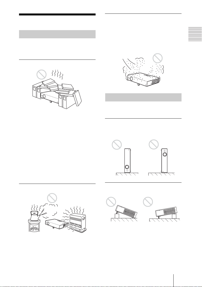
Poorly ventilated
• Allow adequate air circulation to prevent
internal heat build-up. Do not place the
unit on surfaces (rugs, blankets, etc.) or
near materials (curtains, draperies) that
may block the ventilatio n holes. When the
internal heat builds up due to the block-up,
the temperature sensor will function with
the message “High temp.! Lamp off in 1
min.” The power will be turned off
automatically after one minute.
• Leave space of more than 30 cm (11
inches) around the unit.
• Be careful that the ventilation holes may
inhale tininess such as a piece of paper.
Highly heated and humid
7
/8
Very dusty
Avoid installing the un it in a locatio n where
there is a lot of dust ; o therwise , the air filter
will be obstructed. The dust blocking the air
through the filter may cause raising the
internal heat of the projector . Clean it up
periodically.
Unsuitable Condition s
Do not use the pr ojector un der the f ollowing
conditions.
Toppling the unit
Avoid using as the unit topples over on its
side. It may cause malfunction.
Tilting the unit out of the range of
the adjuster setting
Overview
• Avoid installing the unit in a location
where the temperature or humidity is very
high, or temperature is very low.
• To avoid moisture condensation, do not
install the unit in a location where the
temperature may rise rapidly.
Avoid using when the unit is tilted out of th e
range of the adjuster setting. Such
installation may cause color shading or
shorten excessively the lamp life.
Notes on Installation
7
GB
Page 8
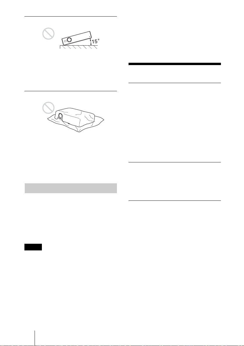
Tilting the unit to the right or left
• When using a screen with an uneven
surface, stripes pattern may rarely appear
on the screen depending on the distance
between the screen and the projector or the
zooming magnifications. This is not a
malfunction of the projector.
Avoid tilting the unit to an angle o f 15°, and
avoid installi ng the unit in any way ot her
than placing on th e floor or susp ending fro m
the ceiling. Such installation may cause
Features
color shading or shorten the lamp life
excessively.
Blocking the ventilation holes
High operability
• Intelligent Auto-setup function
Simply press the power key, and the
projector automatically performs the
setups require d be fore use. The projector
opens the lens protector, corrects the V
Keystone, and sets optimum c onditions for
projection. This function is called
Avoid using something to cover over the
ventilation holes (exhaust/inta k e);
otherwise, the internal heat may build up.
Intelligent Auto-setup.
For easier operations, the ke ys that will be
used frequently are allocated on the top of
the projector.
For details on the ventilation holes (intake/
exhaust), see “Location and Function of
Controls” on page 10.
Short focus lens equipped (VPLCS6/CX6 only)
This projector is equipped wit h a short focus
Usage in High Altitude
When using the projector at an altitude of
1,500 m or higher, tur n on “H igh
Altitude Mode” in the INSTALL SE TTING
menu. Failing to set this mode when using
the projector at high altitudes could have
adverse effects, such as reducing
the reliability of certain components.
lens that allows outputting to a la rger screen
even in a limited space.
Accepts various input signals
• Scan converter loaded
This projector has a build-in scan
converter that converts the input signal
within 1024 × 768 dots (VPL-CX6/EX1)
or 800 × 600 dots (VPL-CS6) .
• Compatible input signals
Notes
• The unit is manufacture d using highprecision techno lo gy . Whe n tra ns p orting
the unit stored in the so ft case, do not drop
the unit or subject it to shock, as this may
cause damage. When storing the unit in the
soft case, disconnect the AC power cord
and all other connecting cables, and store
the supplied accessories in a pocket of the
This projector accepts video signals of
composite, S video, and component as
well as VGA, SVGA, XGA, SXGA
1)
SXGA+
signals, which all can be
1)
displayed.
• Compatible with six color systems
NTSC, PAL, SECAM, NTSC
4.43
2)
, PALM, or PAL-N color system can be selected
automatically.
and
soft case.
..............................................................................................................................................................
1)The SXGA and SXGA+ signal s are available for the VPL-CX6/EX1 only.
2)NTSC
GB
4.43 is the color system used when playing bac k a video recorded on NTSC on a NTSC4.43
system VCR.
8 Features
Page 9

Easy presentation
• Simple setup with external equipment
This projector is preset for 38 kinds
3)
(VPL-CX6/EX1) of input signals. You can
project images from an external sign al
source just by connecting the equipment
with the supplied cable.
You can use the supplied Remote
Commander as the wireless mouse by
connecting the projector to the computer
with the USB cable
control the projector by using the
application software (Projector Station)
4)
. You can also
5)
supplied with the projector from a
computer operated with Windows 98,
Windows 98 SE, Windows ME, Windows
2000 or Windows XP.
Easy-to-use Remote Commander
The Remote Commander is equipped with
various convenient keys, including the D
ZOOM key for zoomin g in on the imag e and
the FREEZE key for keeping the image
projected even if the equipment is
disconnected.
Memory Stick slot (VPL-CX6 only)
By inserting a Memory Stick into the built-
in Memory Stick slot, you can make the
presentation easily without connecting the
computer.
High brightness, high picture
quality
• High brightness
Adopting Sony’ s un iq ue , high-efficiency
optical system allows the 165 W UHP
lamp a light output of 2000 ANSI lumen
(VPL-CX6), 1800 ANSI lumen (VPLCS6) or 1500 ANSI lumen (VPL-EX1).
• High resolution
For VPL-CX6/EX1: Three superhigh-
aperture 0.7-inch XGA panels with
approximately 790,000 pixels, and with
micro-lens array, provide a resolution of
1024 × 768 dots (horizontal/vertical) for
RGB input, and 750 horizontal TV lines
for video input.
For VPL-CS6: Three superhigh-aperture
0.7-inch SVGA panels with
approximately 480,000 pixels provide a
resolution of 800 × 600 dots (horizontal/
vertical) for RGB input, and 600
horizontal TV lines for video input.
High portability
• Light weight/small size/simple design
This projector has been miniaturized to
approx. 2.7 kg (5 lb 15 oz) in weight and
B5-file size.
Its simple yet sophisticated design fits
comfortably in your office.
Overview
Security lock
By setting a password, you can enable the
security lock to function for this
projector.
..............................................................................................................................................................
3)The VPL-CS6 is preset for 25 kind s of input signals .
4)The Remote Commander available for the wir el ess mouse and the US B cable are supplied w ith
the VPL-CS6/CX6 .
5)The application software (Pr ojector Station) can be used with the VPL-CX6 only.
• Windows is a registered trademark of Microsoft Corporation in the United States and/or other
countries.
• IBM PC/AT, VGA, SVGA, XGA and SXGA are registered trademarks of the International
Business Machines Corporation, U.S.A.
• Kensington is a registered trademark of Kensington Technology Group.
• Macintosh is a registered trademark of Apple Computer, Inc.
• VESA is a registered trademark of Video Electronics Standard Association.
• Display Data Channel is a trademark of Video Elect ronics Standard Association.
• Memory Stick and are trademarks of Sony Corporation.
Features
9
GB
Page 10
Location and
Function of Controls
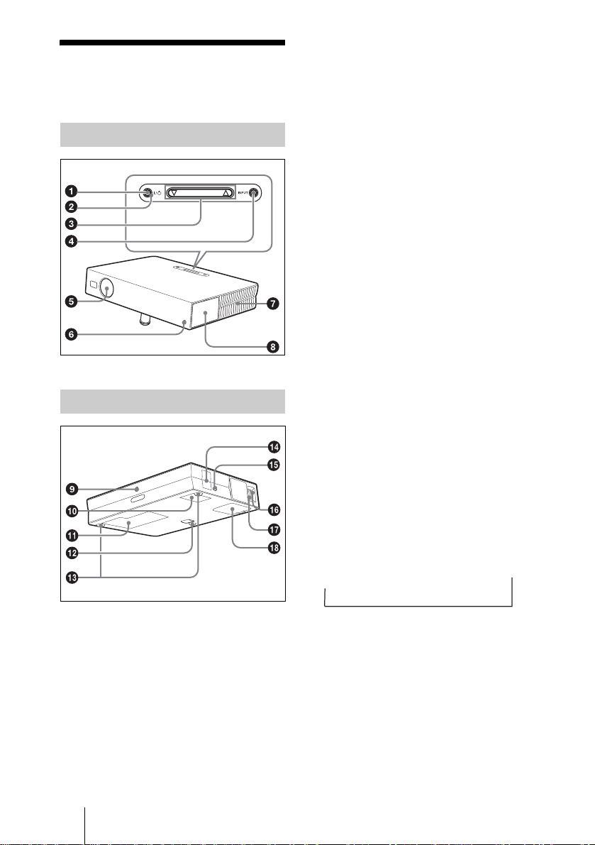
Top/Front/Left Side
TILT
Rear/Right Side/Bottom
For details on steps for turning off the
power, see “To turn off the power” on
page 29.
2 ON/STANDBY indicator (located
around the
Lights up or flashes under the following
conditions:
– Lights in red when a AC power cord is
plugged into a wall outlet. Once in
standby mode, y ou can turn on the
projector with the I / 1 key.
– Lights in green when the power is
turned on.
– Flashes in green while th e coolin g fan
runs after the power is turned off with
the I / 1 key. The fan runs for about
90 seconds after the power is turned
off.
The ON/STANDBY indicator flashes
quickly for the first 60 seconds.
During this time, you cannot light up
the ON/STANDBY indicator with the
I / 1 key.
For details on the LAMP/COVER and
the TEMP/FAN indicators, see on
page 46.
I / 1 key)
3 TILT adjustment key
For details, see“How to use the powered
tilt adjuster” on page 11.
1 I / 1 (on/standby) key
Turns on the projector when the
projector is in standby mode. The ON/
STANDBY indicator around the I / 1
key lights in green when the power is
turned on.
When turning off the power, press
the I / 1 key twice following the
message on the screen, or press and
hold the key for about two seconds.
GB
10 Location and Function of Controls
4 INPUT key
Selects the input signal. Each time you
press the key, the input signal switches
as follows:
INPUT A
t
t
MS t VIDEO t S VIDEO
(VPL-CX6
only)
5 Lens protector (lens cover)
The lens protector automa tically opens
when the power is turned on.
6 Front remote control detector
7 Ventilation holes (exhaust)
Page 11
8 Control/Connector panel
For details, see “Control Panel” and
“Connector Panel” on page12.
9 Rear remote control detector
0 Ventilation holes (intake)
qa Ventilation holes (intake)/Lamp
cover
qs Powered tilt adjuster
qd Adjuster (hind pad)
Turn the adjuster to the right or left for
minor tilt adjustment of the projected
picture.
qf Speaker
qg Security lock
Connects to an optional security cable
(Kensington’s).
Web page address:
http://www.kensington.com/
qh Focus ring
Adjusts the picture focus.
qj Zoom ring
Adjusts the picture size.
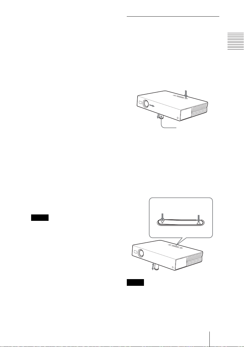
How to use the powered tilt
adjuster
To adjust the height
Adjust the height of the projec tor as follows:
Overview
1 Press the I / 1 key
The lens protector opens, and the
powered tilt adjuster rises automatically.
The adjuster stops at its previously
adjusted position.
Powered tilt
adjuster
2 Press f or F of the TILT key to adjust
the tilt of the projector.
You may press the KEYSTONE key
(VPL-CS6/CX6) or the D KEYSTONE
key (VPL-EX1) on the Remote
Commander to display the Tilt menu and
adjust the tilt using the M/m/</,
keys.
qk Ventilation holes (intake)/air
filter cover
Notes
• Do not place anything nea r the
ventilation holes as it may cause
internal heat build-up.
• Do not place your hand or obj ects
near the ventilation holes as it may
cause the air com i ng out heat buildup.
• To maintain opti mal performance , clean
the air filter every 300 hours.
For details, see “Cleaning the Air
Filter” on page 42.
to lower the
projector
TILT adjustment key
Notes
• Be careful not to let the projector down on
your fingers.
• Do not push hard on the top of the projector
with the powered tilt adjuster out.
It may be occurred malfunction.
Location and Function of Controls
TILT
to raise the
to raise the
projector
projector
11
GB
Page 12
65
1
Control Panel
POWER
SAVING
INPUT A
MENU
PUSH
ACCESS
AUDIO VIDEO
PRO
AUDIO VIDEO
ACCESS
1 POWER SAVING indicator
Lights up when the projector is in power
saving mode. When “Power Saving” in
the SET SETTING menu is set to “ON,”
the projector goes into power saving
mode if no signa l is input for 10 minu tes.
Although the lamp goes out, the c ooling
fan keeps runnin g. The power saving
mode is canceled when a signal is input
or any key is pressed. In power saving
mode, any key does not function for the
first 60 seconds after the lamp goes o ut.
2 MENU key
Displays the on-screen menu. Press
again to clear the menu.
3 Arrow keys (f/F/g/G)
Select the menu or to make various
adjustments.
4 ENTER key
Enters the settings of items in the menu
system.
TEMP/FAN
LAMP/COVER
INPUT A
TEMP/FAN
LAMP/COVER
S VIDEO
S VIDEO
ENTER
POWER
SAVING
MENU
PUSH
ENTER
1
2
3
4
5 TEMP (Temperature)/FAN
indicator
Lights up or flashes under the following
conditions:
– Lights up when temperature inside the
projector becomes unusually high.
– Fashes when the fan is broken.
For details on the TE MP/FAN indicator,
see page 46.
6 LAMP/COVER indicator
Lights up or flashes under the following
conditions:
– Lights up when the lamp has reached
the end of its life or becomes a high
temperature.
– Flashes when the lamp cover or air
filter cover is not secured firmly.
For details on the LAMP/COVER
indicator, see page 46.
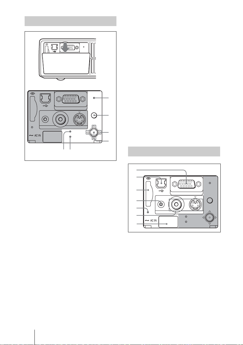
Connector Panel
2
POWER
S VIDEO
SAVING
MENU
PUSH
ENTER
3
INPUT A
4
PRO
5
6
7
AUDIO VIDEO
ACCESS
TEMP/FAN
LAMP/COVER
1 INPUT A connector (HD D-sub
15-pin, female)
Connect to external equipment such as a
computer.
Connects to the monitor output on a
computer using t he supplied cable.
When inputting a component or 15k
RGB signal, use an optional cable.
For details, see “To connect a 15k RGB/
Component equipment” on page 21.
GB
12 Location and Function of Controls
Page 13
2 USB connector (USB plug for
q
upstream, 4-pin)
Connect to the USB connector on a
computer. When you connect the
projector to the computer, you can
control the mouse function with the
supplied Remote Com mander. (When
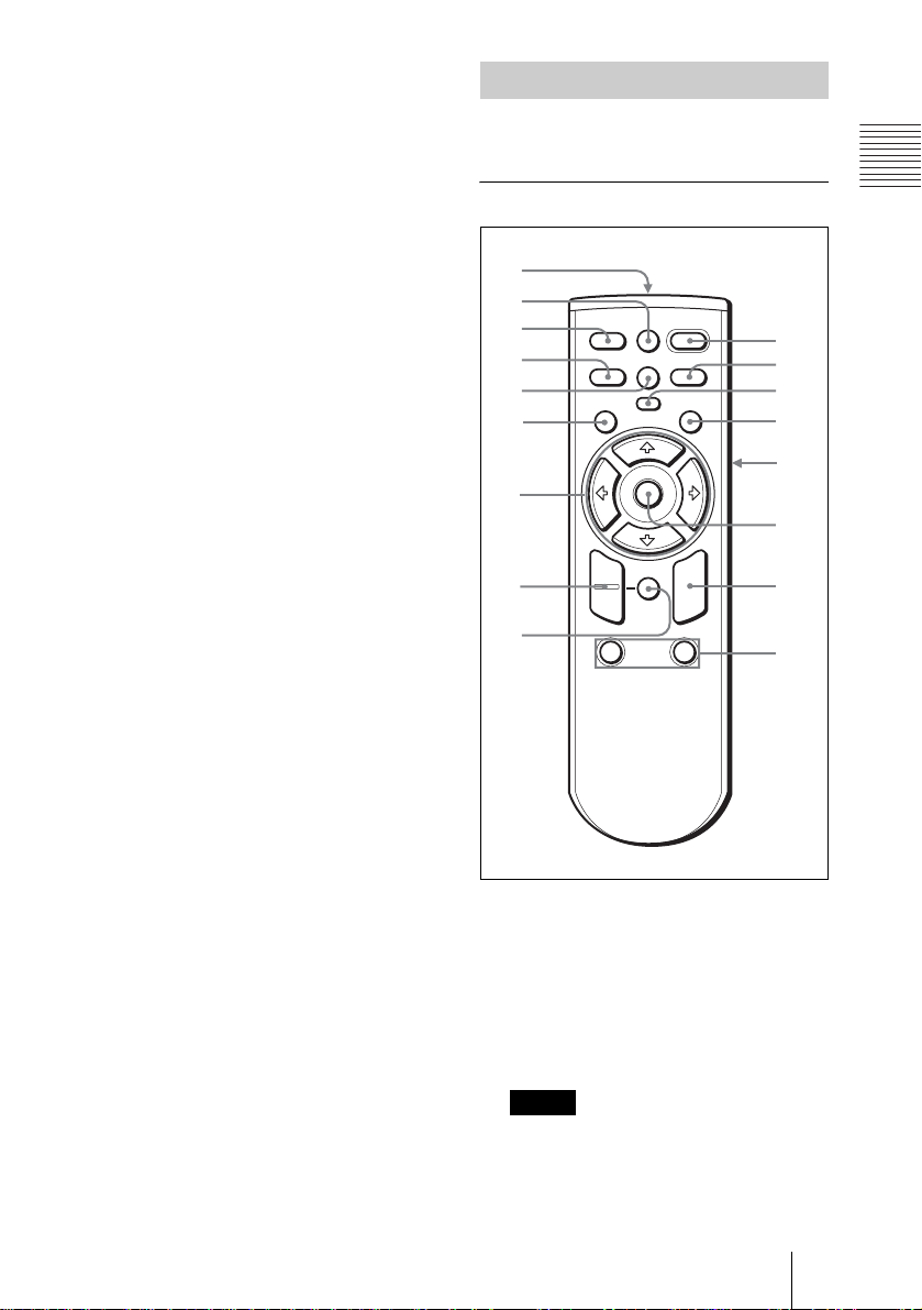
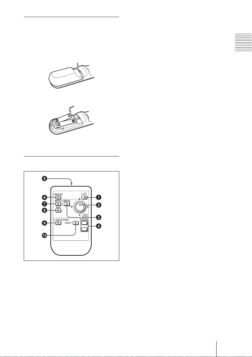
Remote Commander
The keys that have the same names as those
on the control panel function identically.
For VPL-CS6/VPL-CX6
Overview
you use the VPL-EX1, an optional
Remote Commander is required to
qf
qd
qs
qa
0
9
g
MS SLIDE
KEYSTONE
PIC
MUTING
I / 1
APA
1
2
3
4
5
5
a
b
FREEZE
INPUT
MENU ENTER
control the mouse function with a
Remote Commander.) The supplied
application software (VPL-CX6 only)
can be installed in the computer attached
to this connector.
3 Memory Stick slot (VPL-CX6
only)
The Memory Stick can be in serted.
Never insert an object other than the
Memory Stick.
For details, see the attached “O perating
Instructions” for Memory Stick.
4 AUDIO (stereo minijack)
connector
When listening to soun d output fro m the
computer, connect to the audio output of
8
7
+
–
D ZOOM
12
FUNCTION
R
CLICK
5
6
c
RESET
the computer.
When listening to soun d output fro m the
VCR, connect to the audio output of the
VCR.
5 Access lamp (VPL-CX6 only)
Lights during having acce ss to th e
Memory Stick.
Do not remove the Memory Stick
while the access lamp is lit.
6 Video input connector
Connect to external video equipment
such as a VCR.
• VIDEO (phono type): Connects to
the composite vi deo output of vide o
equipment.
• S VIDEO (mini DIN 4-pin):
Connects to the S video output (Y/C
video output) of video equipment.
7 AC IN socket
Connects the supplied AC po wer cor d.
I / 1 (on/standby) key
1
2 APA (Auto Pixel Alignment) key
Adjusts a picture clearest automatically
while a signal is input from a computer.
Used when “Smart APA” in the SET
SETTING menu is set to “Off.”
Normally set to “On.”
Notes
• Press the APA key when the full image
is displayed on the screen. If there are
black edges around the image, the APA
function will not function properly an d
the image may extend beyo nd the scree n.
Location and Function of Controls
13
GB
Page 14

• You can cancel the adju st m ent by
pressing the APA key again while
“Adjusting” appears on the screen.
• The picture may not be adjusted properly
depending on the ki nds of input signals.
• Adjust the items “Dot Phase,” “H Size”
and “Shift” in the IN PU T SE TTING
menu when you adjust the picture
manually.
For details, see “To connect an IBM PC/
AT compatible computer” on page 19”.
7 RESET key
Resets the value of an item back to its
factory preset value or returns the
enlarged image back to its original size.
This key functions when the menu or a
setting item is displayed on the screen.
3 PIC MUTING key
Used to mute the picture temporarily.
Press again to restore the picture.
4 ENTER key
5 Keys emulate a mouse
Functions like a mouse of a computer
connected via USB with the projector.
a) L Click key (Rear): Functions as
the left button on a mouse.
b) Joystick
c) R Click key: Func tions as the righ t
button on a mouse.
Note
These keys function as mouse buttons of a
computer only when the projector is
connected to the computer using the USB
cable.
For details, see “To control the
computer using the supplied Remote
Commander” on page 26.
6 FUNCTION 1, 2 keys (VPL-CX6
only)
When you connect the projector with a
computer, you can open a file on t he
screen by just pressing the FUNCTION
key. This will enhance your
presentation. To use this function,
allocate a file to the FUNCTION key by
using the supplied application software.
For details, see the README file and
the HELP file supplied with the
application software.
Note
Connect a computer to the projector using
the USB cabl e t o ac tiv at e t he F UNCT ION
keys.
8 D ZOOM (Digital Zoom) +/– key
Enlarges the image at a desired location
on the screen.
+:Pressing the + key once displa ys the
icon. This icon indicates the point yo u
want to enlarge. Use an arrow key (M/
m/</,) to move the icon to the
point to be enlarged. Press the + key
repeatedly until the image is en larged
to your requirements.
–: Pressing the – key reduces an imag e
that has been enlarged with the D
ZOOM + key.
9 Arrow keys (M/m/</,)
0 MENU key
qa KEYSTONE key
Used to adjust the tilt of the projector , or
the trapezoidal distortion of the image
manually. Each time you press thi s key,
the Tilt menu and t he V K eys tone m enu
is displayed alternately. Use the arrow
keys (M/m/</,) for the adjustment.
qs INPUT key
qd FREEZE key
Used to freeze the picture project ed. To
cancel the frozen pictu re, press the key
again.
qf MS SLIDE key (VPL-CX6 only)
Used to execute the slide show. When
the input signal is other than MS, it
switches to MS. To begin the slide show,
press the key again .
qg Infrared transmitter
GB
14 Location and Function of Controls
Page 15
To install batteries
1 Push and slide to open the lid, then
install the two size AA (R6) batteries
(supplied) with the correct polarity.
While pressing the lid, slide it.
Be sure to install the battery
# side.
from the
2 Replace the lid.
4 D ZOOM +/
Enlarges the image at a desired location
on the screen.
+:Pressing the + key once displays the
icon. This icon indicates the poin t you
want to enlarge. Use an arrow key (M/
m/</,) to move the icon to the
point to be enlarged. Press the + key
repeatedly until the image is enl arged
to your requirements.
– key
–:Pressing the – key reduces an image
that has been enlarged with the D
ZOOM + key.
5 Infrared transmitter
6 FREEZE key
Used to freeze the picture projected. To
cancel the freeze function, press the key
again.
7 INPUT key
Overview
For VPL-EX1
1 I / 1 (on/standby) key
2 ENTER/arrow key (M/m/</,)
Press the center of the key to use
ENTER.
3 MENU key
8 APA (Auto Pixel Alignment) key
Adjusts a picture clearest automatically
while a signal is input from a computer.
Used when “Smart APA” in the SET
SETTING menu is set to “Off.”
Normally set to “On.”
9 D KEYSTONE key
Used to adjust the tilt of th e projector, or
the trapezoidal distortion of th e image
manually. Each time you press this key,
the Tilt menu and the V Keystone menu
is displayed alternately. Use the arrow
key (M/m/</,) for the adjustment.
q; RESET key
Resets the value of an item back to its
factory preset value or returns the
enlarged image back to its original size.
This key functions when t he menu or a
setting item is displayed on the screen.
Location and Function of Controls
15
GB
Page 16
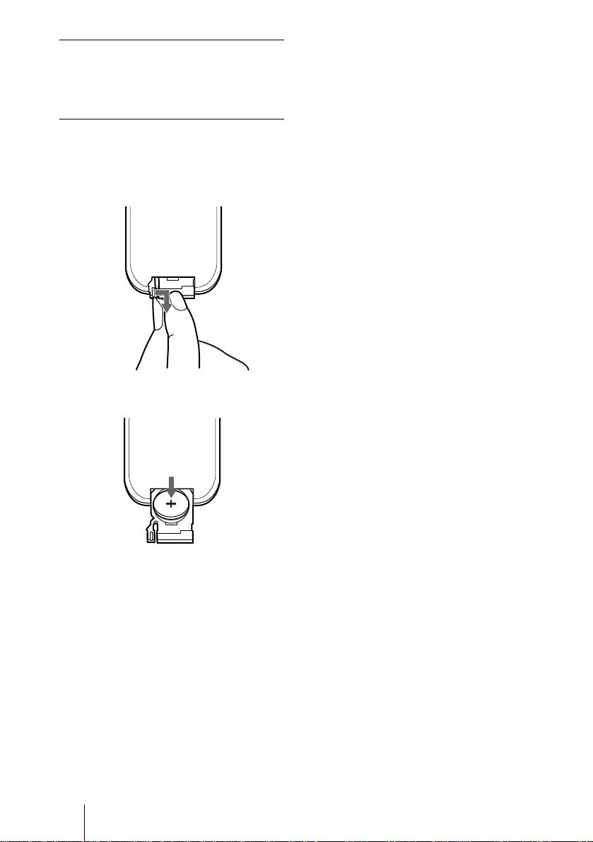
Before using the Remote
Commander
Pull out the clear film from the lithium
battery holder.
To replace battery
1 Release the lock of the lithium battery
holder by picking it, and pull out the
holder from the Remote Commander.
2 Install the lithium battery.
+ side facing
upward
3 Put the lithium battery holder back
into the Remote Commander.
Notes on the lithium battery
• Keep the lithium battery out of the reach of
children.
• Should the battery be swallowed,
immediately con s ult a doctor.
Notes on Remote Commander
operation
• Make sure that nothing obstructs the
infrared beam between the Remote
Commander and the remote control
detector on the projector . Direct the
Remote Commander toward the front or
rear remote control detector.
• The operation range is limited. The shorter
the distance between the Remote
Commander and the projector is, the wider
the angle within which the commander ca n
control the projector becomes.
GB
16 Location and Function of Controls
Page 17
B Setting Up and Projecting
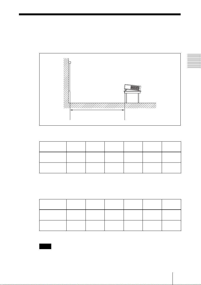
Installing the Projector
This section describes how to install the projector.
The distance between the lens and the screen varies depending on the size of
the screen. Use the following table as a guide.
Distance between the screen and
the center of the lens
VPL-CS6/VPL-CX6
Unit: m (feet)
Screen size
(inches)
Minimum
Distance
Maximum
Distance
There may be a slight dif f erence between the act ual value and the design va lu e shown
in the table above.
40 60 80 100 120 150
1.2
(3.9)
1.5
(4.9)
1.9
(6.2)
2.3
(7.6)
2.5
(8.2)
3.0
(9.8)
3.2
(10.5)
3.8
(12.5)
3.8
(12.5)
4.6
(15.1)
Setting Up and Projecting
4.7
(15.4)
5.7
(18.7)
VPL-EX1
Unit: m (feet)
Screen size
(inches)
Minimum
Distance
Maximum
Distance
There may be a slight dif f erence between the act ual value and the design va lu e shown
in the table above.
Note
40 60 80 100 120 150
1.5
(4.9)
1.9
(6.2)
2.3
(7.5)
2.9
(9.5)
3.1
(10.2)
3.8
(12.5)
3.9
(12.8)
4.8
(15.7)
4.7
(15.4)
5.7
(18.7)
(19.4)
(23.6)
5.9
7.2
When using the projector by suspending it from the ceilling, consult with
qualified Sony personel. (fee charged)
Installing the Projector
17
GB
Page 18

Connecting the Projector
When you connect the projector, make sure to:
• Turn off all equipment before making any connections.
• Use the proper cables for each connection.
• Insert the cable plugs firmly; loose connections may increase noise and
reduce performance of picture signals. When pulling out a cable, be sure to
pull it out from the plug, not the cable itself
To connect the projector, refer to the illustrations on the next and the
following pages.
Connecting with a Computer
This section describes how to connect the projector to a computer.
For more information, refer to the computer’s instruction manual.
Notes
• The projector accepts VGA, SVGA, XGA, SXGA (VPL-CX6/EX1 only) and
SXGA+ (VPL-CX6/EX1 only) signals. However, we recommend that you set the
output mode of your computer to XGA mode (VPL-CX6/EX1) or SVGA mode
(VPL-CS6) for the external monitor.
• If you set your computer , such as a notebook type, to o ut put the signal to both you r
computer’s display and the externa l monitor, the pictu re of the ext ernal monito r may
not appear properly. Set your computer to output the signal to only the external
monitor.
For details, refer to the computer’s operating instructions supplied with your
computer.
• This projector is compatible with a DDC2B (Digital Data Channel 2B). If your
computer is compatible with a DDC, turn t he p rojector on a ccording to t he foll owing
procedures.
1 Connect the projecto r to the c omputer by usin g the su pplied HD D-sub 1 5 pin cab le.
2 Turn the projector on.
3 Start the computer.
GB
18 Connecting the Projector
Page 19

To connect an IBM PC/AT compatible computer
Left side
POWER
SAVING
INPUT A
MENU
PRO
ACCESS
AUDIO VIDEO
S VIDEO
TEMP/FAN
LAMP/COVER
PUSH
ENTER
HD D-sub 15-pin cable
(supplied)
to monitor output
Computer
Stereo audio connecting cable (not supplied)
USB cable (supplied only VPL-CS6/CX6)
(Connect the USB cable to use a wireless
mouse or the Projector Station.)
a) Use a no-resistance cable.
On the USB function
When connecting the projector to a computer by using the USB cable for the
first time, the computer recognizes the following devices automatically.
1 USB hub (general use) (VPL-CX6 only)
2 USB human interface device (wireless mouse function)
3 USB human interface device (projector control function) (VPL-CX6 only)
Recommended operating environment
When you use the USB function, connect the USB cable as illustrated above.
This application software and the USB function can be used on a computer
loaded with Windows 98, Windows 98 SE, Win dows ME, Windows 2000 or
Windows XP preinstall mo de ls .
Notes
• Your computer may not st art correctly when c onnected to the project or via the USB
cable. In this case, disconnect the USB cable, restart the computer, then connect the
computer to the pr oj ector using the USB cabl e.
• This projector is not gu ar ant eed for suspend, stan dby mode. When you us e the
projector in suspend, standby mode, disconnect the projector from the USB port on
the computer.
• An optional Remote Com mander and USB cabl e are required when cont r ol ling the
mouse of the computer from the VPL-EX1.
• Operations are not guaranteed for all the recommended computer environments.
a)
to USB connector
to audio output
Setting Up and Projecting
Connecting the Projector
19
GB
Page 20

To connect a Macintosh computer
To connect a Macintosh computer equipped with video output connector of a
type having two rows of pins, use a commercially available plug adaptor.
When you connect a USB capable Macintosh computer using the USB cable
to the projector, wireless mouse functions become available.
Note
The supplied software does not run on Macintosh computer.
Connecting with a VCR or 15k RGB/Component Equipment
This section describes how to connect the projector to a VCR and 15k RGB/
component equipment.
For more information, refer to the instruction manuals of the equipment you
are connecting.
To connect a VCR
Left side
POWER
SAVING
INPUT A
MENU
ACCESS
PRO
AUDIO VIDEO
S VIDEO
TEMP/FAN
LAMP/COVER
PUSH
ENTER
a) Use a no-resistance ca bl e .
Video cable (not supplied) or S-Video cable
(not supplied)
Stereo audio connecting cable
(not supplied)
a)
to audio
output
to video output
to S
video
output
VCR
GB
20 Connecting the Projector
Page 21

To connect a 15k RGB/Component equipment
Left side
POWER
SAVING
INPUT A
MENU
PRO
ACCESS
AUDIO VIDEO
S VIDEO
TEMP/FAN
LAMP/COVER
PUSH
ENTER
a) Use a no-resistance ca bl e .
Notes
• Set the aspect ratio using “Wide M ode” in the INPUT SETTIN G me nu according to
the input signal.
• When you connect the unit to 15k RGB or component video equipment, select video
GBR or component with the “Input-A Signal Sel.” setting in the SET SETTING
menu.
• Use the composite sync si gnal when you input the external sync signa l fro m 15k
RGB/component equi pm ent.
SMF-402 Signal Cable
(not supplied)
HD D-sub 15-pin (male) ↔ 3 × phono jack
Stereo audio connecting cable
(not supplied)
a)
to audio
output
15k RGB/Component equipment
to RGB/
component
output
Setting Up and Projecting
Connecting the Projector
21
GB
Page 22

Selecting the Menu Language
You can select one of thirte en la nguag es for d isplay ing the menu a nd ot her onscreen displays. The factory setting is English.
To change the menu language, proceed as foll ows:
INPUT A
PRO
AUDIO VIDEO
ACCESS
Front remote control detecto r
I / 1
MS SLIDE
FREEZE
KEYSTONE
INPUT
MENU ENTER
PIC
MUTING
APA
S VIDEO
TEMP/FAN
LAMP/COVER
POWER
SAVING
MENU
PUSH
ENTER
For VPL-CS6/CX6 For VPL-EX1
1 Open the connector panel, then plug the AC power cord into a wall outlet.
2 Press the I / 1 key to turn on the projector.
3 Press the MENU key.
The menu appears.
The menu presently selected is shown as a yellow button.
PICTURE SETTING
Picture Mode: Standard
Adjust Picture...
Volume: 30
GB
22 Selecting the Menu Language
Input A
Page 23

4 Press the M or m key to select the MENU SETTING menu, then press the
, or ENTER key.
The selected menu appears.
Input A
:
:
:
:
A
5 Press the M or m key to select “Language,” then press the , or ENTER
key.
:
:
:
:
Input A
6 Press the M, m, < or , key t o se lect a l angua ge, then pr ess th e ENT ER
key.
The menu changes to the selected language.
Setting Up and Projecting
To clear the menu
Press the MENU key.
The menu disappears automatically if a key is not pressed for one minute.
Selecting the Menu Language
23
GB
Page 24

Projecting
5
TILT
Rear remote control
detector
MS SLIDE
FREEZE
KEYSTONE
INPUT
MENU ENTER
PIC
MUTING
For VPL-CS6/CX6
6
7
I / 1
APA
ON/STANDBY
indicators
24
For VPL-EX1
1 Open the connector panel, plug the AC power cord into a wall outlet, then
connect all equipment.
The ON/STANDBY indicator lights in red and the projector goes into
standby mode.
2 Press the I / 1 key.
The ON/STANDBY indicator lights in green and the Intelligent Auto-setup
starts. The lens prot ector op ens, and the powered t ilt adjuster r ises and stops at
the previously adjusted position.
GB
24 Projecting
Note
When the projector is turned on, the Startu p screen is projected (VPL-CX6
only).
For details on the Startup screen, see the attached "Operating Instructions for
Memory Stick".
3 Turn on the equipment connected to the projector.
Depending on the type of your computer, for example a notebook, or an all-inone LCD type, you may have to switch the computer to output to the projector
by pressing certain keys (e.g., , etc.), or by changing your
computer’s settings.
VGA
LCD
//
,
Page 25

F7
or
Fx
Fn
4 Press the INPUT key to select the input source.
To input from Press INPUT to disp la y
Computer connected to the INPUT A connector INPUT A
Memory Stick inserted to the Memory Stick slot
(VPL-CX6 only)
Video equipment connected to th e V I D E O in put
connector
Video equipment connected to the S V IDEO input
connector
Smart APA (Auto Pixel Alignment) adjusts the picture of the connected
equipment so that it is pr ojected clearly.
Notes
• If “Auto In put S ear ch ” i s set to “ On, ” th e proj ec tor se arch e s for t he sign al s fr om
the connected equipment and displays the input channel where the input signals
are found.
For details, see “Auto Input Search” in the SET SETTING menu on
page 37.
• The Smart APA is effective for the input signal from a computer only.
MS
VIDEO
S VIDEO
Setting Up and Projecting
5 Adjust the position of the picture by pressing the TILT key.
To adjust the posi tion of the picture using the Remote Commander, press the
KEYSTONE key (VPL-CS6/CX6) or the D KEYSTONE key (VPL-EX1) on
the Remote Commander to display the Tilt menu and adjust the tilt using the
M/m/</, keys.
For details on the TILT adjustment key, see “How to use the powered tilt
adjuster” on page 11.
Note
When you adjust the powered tilt adjuster with the TILT key, the automatic
keystone adjustment is per fo rme d a t the same time. If you do not wa nt to perform
the automatic keystone adjustment, set the V Keystone menu to “Manual.” (See
page 39.)
6 Turn the zoom ring to adjust the size of the picture.
7 Turn the focus ring to adjust the focus.
Projecting
25
GB
Page 26

Note
The auto V keystone adjustment may not correct the trapezoidal distortion perfectly,
depending on the room temperature or the screen angle. In this case, adjust it manually.
Press the KEYSTONE key (VPL-CS6/CX6) or the D KEYSTONE key ( VPL-EX1) on
the Remote Commander until “V Keyst one” appears o n the sc reen, and adjust th e value
with the M/m/</, key. The corrected value is effective until the power turn off.
Attention
Looking into the lens when projecting may cause injury to your eyes.
To switch from the Intelligent Auto-setup function to manual adjustments
You can switch the following functions of the Intelligent Auto-setup to manual
adjustments using the menu.
V Keystone correction (correction of trapezoidal distortion)
•
Set “V Keystone” in the INSTALL SETTING menu to “Manual.”
• Smart APA (A uto Pixel Al i gnment)
Set “Smart APA” in the SET SETTING menu to “Off.”
• Auto Input Search
Set “Auto Input Search” in the SET SETTING menu to “Off.”
For details on the menu operations, see “Using the MENU” on page 32.
To adjust the volume
The volume can be adjusted in the on-screen menu. See “Volume” in the
PICTURE SETTING menu on page 34.
To mute the picture temporarily (VPL-CS6/CX6 only)
Press the PIC MUTING key on the Remote Commander. Press it again to
restore the picture.
To control the computer using the supplied Remote Commander
When you connect an IBM PC/AT compatible computer to the projector by
using the USB cable, you can control the mouse of the computer using the
Remote Commander.
The R/L CLICK keys and joystick function as follows.
Key and joystick Function
R CLICK (front) Right button
L CLICK (rear) Left button
Joystick Corresponds with the movements of the mouse
For details on USB connection, see “To connect an IBM PC/AT compatible
computer” on page 19.
Note
Make sure that nothing obstructs the infrared beam between the Remote Commander
and the remote control detector on the projector.
GB
26 Projecting
Page 27

To Use the security lock
1 Press the MENU key and then, in the INSTALL SETTING menu, turn on
the
“Security Lock” setting.
2 Enter the password.
Use the MENU, M/m/</,, and ENTER keys to enter the four-digit
password. (The default initia l pa ssword settin g is “ ENTER, ENTER , ENTER,
ENTER”. After this is entered you can put in your own password. Therefore
when you use this function for the first time, please input “ENTER” four
times.)
Next, the screen for entering the new password is displayed. (Enter the
password at this screen even if you want to keep the current password.)
Enter password key.
Password required for power-on.
Use: Cancel: Other key
Enter new password key.
Power-on cannot be performed
without the password.
Use: Cancel: Other key
Setting Up and Projecting
3 Enter the password again to confirm.
Re-enter new password key.
Be sure to remember this password.
Use: Cancel: Other key
If the password is entered incorrectly, the menu screen displays an “Invalid
Password” message.
INSTALL SETTING
Tilt...
V Keystone: Auto...
Image Flip: Off
Background: Blue
Lamp Mode: Standard
High Altitude Mode
Security Lock: Off
Invalid Password!
: Off
Input A
X
Projecting
27
GB
Page 28

4 The setting for security lock is completed.
INSTALL SETTING
Tilt...
V Keystone: Auto...
Image Flip: Off
Background: Blue
Lamp Mode: Standard
High Altitude Mode
Security Lock: On
Security Lock enabled!
: Off
Input A
X
5 Turn the main power off and disconnect the AC power cord.
The security lock is set to on, then it becomes effective. The screen for entering
the password is displayed when the power is turned on the next time.
Notes
• You will not be able to use the projector if you forget your password and the password
administrator is not availa ble. Be please aware th at using the security lock can prevent
valid usage in such cases. It is recommended that you make a note of the selected
password.
• If you fail to enter the correct password after three tries, the pr ojector canno t be used.
In this ca se, press the I / 1 k ey to turn off the power.
• The security lock will not be set if the correct password is not entered in steps 2 and
3, or a key other than the MENU, arrow keys (M/m/</,), and ENTER key is
pressed.
• If you call the customer service center because you have forgotten the password, you
will need to be able to verify the projector’s serial number and your identity. (This
process may diff er in other countries.) On ce your identity has b een confirmed, we
will provide you wi th the password.
GB
28 Projecting
Page 29

To turn off the power
1 Press the I / 1 key.
“POWER OFF? Please press I / 1 key again .” appears to confirm that you
want to turn off the power.
Note
A message disappears if you press any key except the I / 1 key, or if you do not
press any key for five seconds.
2 Press the I / 1 key again.
The powered tilt adjuster is put away in the projector and the lens protector
closes. The ON/ST ANDBY indi cator fla shes in gree n and the fa n continu es to
run for about 90 seconds to reduce the internal heat. Also, the ON/STANDBY
indicator flashes quickly for the first 60 secon ds. During this time, you will not
be able to light up again the ON/STANDBY indicator with the I / 1 key.
3 Unplug the AC power cord from the wall outlet after the fan stops running
and the ON/STANDBY indicator lights in red.
When you cannot confirm the on-screen message
When you cannot confirm the on-screen message in a certain condition, you can
turn off the power by holding the I / 1 key for about two seconds.
Note
Do not unplug the AC power cord while the fa n i s st i ll running; otherwise, the fan
will stop even thou gh the internal heat is st il l hi gh, which could result in a br eakdown
of the projector.
On air filter
To maintain optimal performance, clean the air filter every 300 hours.
For details, see “Cleaning the Air Filter” on page 42.
Setting Up and Projecting
Projecting
29
GB
Page 30

Effective Tools for Your Presentation
To enlarge the image (Digital Zoom function)
You can select a point in the image to enlarge. This function works when a
signal from a computer is input, or when a still picture (except a movie picture)
stored in a Memory Stick is projected (VPL-CX6 only).
This function does not work when a video signal is input.
1 Project a normal image, and press the D ZOOM + key on the Remote
Commander.
The digital zoom icon appears in the center of the image.
Digital zoom icon
2 Move the icon to the point on the image you want to enlarge. Use the arrow
key (M/m/</,) to move the icon.
3 Press the D ZOOM + key again.
The image where the icon is located is enlarged. The enlargement ratio is
displayed on the screen for a few seconds.
By pressing the + key repeatedly, the image size increases (ratio of
enlargement: max. 4 times.)
GB
30 Projecting
Use the arrow key (M/m/</,) to scroll the enlarged image.
To return the image back to its original size
Press the D ZOOM – key.
Just pressing the RESET key returns the image back to its original size
immediately.
Page 31

To freeze the image projected (Freeze function)
Press the FREEZE key. “Freeze” appears when the key is pressed. This
function works when a signal from a computer is input or when a still picture
stored in a Memory Stick is projected (VPL-CX6 only).
To restore the original screen, press the FREEZE key again.
Setting Up and Projecting
Projecting
31
GB
Page 32

B Adjustments and Settings Using the Menu
1 Press the MENU key.
Using the MENU
The projector is equipped with an on-screen
menu for making various adjustments and
settings. The setting items are d isplayed in a
pop-up menu or in a sub menu. If yo u select
an item name followed by dots (...), a sub
menu with setting items appear. You can
change the tone of the menu display and the
menu language displa ye d in the on - s cre e n
menu.
To change the menu langu age, see
“Selecting the Menu Language” on page 22.
Display items
Input signal indicator
The menu appears.
The menu presently selected is shown as
a yellow button.
SET SETTING
Smart APA: On
Auto Input Search:
Input-A Signal Sel.:
Color System: Auto
Power Saving: Off
IR Receiver: Front & Rear
Illumination: On
2 Use the M or m key to select a menu,
then press the , or ENTER key.
The selected menu appears.
3 Select an item.
Video
NTSC 3.58
Input signal setting indicator
Picture adjustment menu
Contrast
Input signal indicator
Shows the selected input channel. is
x
displayed when no signal is input. You can
hide this indicator using “Status” in the
MENU SETTING menu.
Input signal setting indicator
For Input A: Shows “Computer,”
“Component” or “Vid eo GB R.”
For Video/S Video inp ut : Shows “Auto” or
the “Color System” setting in the SET
SETTING menu.
Use the M or m key to select the item,
then press the , or ENTER key.
The setting items are displayed in a pop up menu or in a sub menu.
Pop-up menu
Setting items
Menu
MENU SETTING
Status:
Language:
Menu Position:
Menu Color:
Sub menu
Menu Setting items
Off
Computer
Top left
Bottom Left
Center
Top Right
Bottom Right
On
English
Input A
Selected input
signal
Input A
A
GB
32 Using the MENU
PICTURE SETTING
ADJUST PICTURE
Contrast: 80
Brightness: 50
RGB Enhancer: 20
Gamma Mode: Graphics
Color Temp: High
Standard
Input A
Page 33

4 Make the setting or adjustment on an
item.
• When changing the adjustment level:
To increa se the numb er, press the
, key.
To decrease the number, press the m
or < key.
Press the ENTER key to restore the
previous screen.
• When changing the setting:
Press the M or m key to change the
setting.
Press the ENTER or < key to restor e
the previous screen.
When setting the Menu Language, see
“Selecting the Menu Languag e” on page 22.
To clear the menu
Press the MENU key.
The menu disappears automatically if a key
is not pressed for on e minute.
To reset items that have been
adjusted
Press the RESET key on the Remote
Commander.
“Complete!” appears on the screen and the
settings appearing on the screen are reset
to their factory preset values.
Items that can be reset are:
• “Contrast,” “Brightness,” “Color,” “Hue,”
“Sharpness” and “RGB Enhancer” in the
Adjust Picture... menu.
• “Dot Phase,” “H Size,” and “Shift” in the
Adjust Signal... menu
M or
About the menu display
You can set the display positio n of the menu,
intensity of the background picture and tone
of the menu items as you like.
For details, see “The MENU SETTING
Menu” on page38.
Adjustments and Sett in gs Using the Menu
About the memory of the settings
The settings are automatically stored in the
projector memory.
If no signal is input
If there is no input signal, “Cannot adjust
this item.” appears on the screen.
Using the MENU
33
GB
Page 34

The PICTURE
SETTING Menu
The PICTURE SETTING menu is used for
adjusting the pictur e or vo lum e .
Items that cannot be ad justed depending on
the input signal are not displayed in the
menu.
For details on the unadjustable items, see
page 51.
Adjust Picture...
When the video signal is input
PICTURE SETTING
ADJUST PICTURE
Contrast: 80
Brightness: 50
Color: 50
Hue: 50
Sharpness: Middle
Color Temp.:
Standard
Low
Video
PICTURE SETTING
Picture Mode Standard
Adjust Picture...
Volume: 30
Input A
Menu Items
Picture Mode
Selects the picture mode.
Dynamic: Emphasizes the contrast to
produce a “dynamic” pi cture.
Standard: Normally select this setting. If
the picture has roughness with the
“Dynamic” setting, this setting reduces
the roughness.
Volume
Adjusts the volume.
Adjust Picture... Menu Items
The unit can store the setting values of the
following sub menu items for each
“Dynamic” or “Standard” picture mode
separately.
When the RGB signal is input
PICTURE SETTING
ADJUST PICTURE
Contrast: 80
Brightness: 50
RGB Enhancer: 20
Gamma Mode: Graphics
Color Temp.: High
Standard
Input A
Contrast
Adjusts the picture contrast. The higher the
setting, the greater the cont rast between a
dark portion and a bright portion of the
picture. The lower the setting, the lower the
contrast.
Brightness
Adjusts the picture brightness. The higher
the setting, the brighter the p icture. The
lower the setting, the darker the picture.
Color
Adjusts color intensity. The higher the
setting, the greater the intensity. The lower
the setting, the lower the intensity.
Hue
Adjusts color tones. The higher the setting,
the picture becomes greenish. The lower the
setting, the picture beco mes purplish.
GB
34 The PICTURE SETTING Menu
Page 35

Sharpness
Selects the picture sharpness from among
“High,” “Middle” and “Low.” The “High”
setting makes the picture sharp; the “Low”
setting makes it soft.
RGB Enhancer
Adjusts the picture sharpness when RGB
signals ar e i nput.
The higher the setting, the sharper the
picture. The lower the setting, the softer the
picture.
The INPUT SETTING
Menu
The INPUT S ETTING menu is used to
adjust the input signal.
Items that cannot be adjusted depending on
the input signal are not displayed in the
menu.
For details on the unadjustable items, see
page 51.
Gamma Mode
Selects a gamma correction curve.
Graphics: Improves the reproduction of
halftones. Photos can be reproduc ed in
natural tones.
Text: Contrasts black an d w hite. Suitable
for images that contain lots of text.
Color Temp.
Adjusts the color temperature.
High: Makes the white color bluish.
Low: Makes the white color reddish.
When the video signal is input
INPUT SETTING
Wide Mode: Off
Video
When the RGB signal is input
INPUT SETTING
Adjust Signal...
Scan Converter: On
Input A
MENU Items
Wide Mode
Sets the aspect ratio of the picture. When
inputting 16:9 (squ eezed) signal from
equipment such as a DVD player, set to On.
Off: When the pi cture with ratio 4:3 is input.
On: When the picture with ratio 16:9
(squeezed) is input.
Adjustments and Sett in gs Using the Menu
Note
Note that if the projector is used for profit or for
public viewing, modifying the original picture
The INPUT SETTING Menu
35
GB
Page 36

by switching to the wide mode may constitute
an infringement of the rights of authors or
producers, which are legally protected.
Adjust Signal... Menu Items
(Only when the RGB signal is input)
INPUT SETTING
SIGNAL SETTING
Dot Phase: 24
H Size: 1504
Shift: H: 181 V: 34
Input A
Dot Phase
Adjusts the dot phase of the LCD panel and
the signal ou tput from a comp u t e r .
Adjust the picture further for finer picture
after the picture is adjusted by pressing the
APA key.
Adjust the picture to where it looks clearest.
H Size
Adjusts the horizontal size of picture output
from a connector. The higher the settin g, the
larger the horizontal size of the picture. The
lower the setting, the smaller the horizontal
size of the picture. Adjust the setting
according to the dots of the input signal.
For details on the suitable value for the
preset signals, see page 52.
Shift
Adjusts the position of the pic ture. H adjusts
the horizontal posi tion of the picture.V
adjusts the vertical position of the picture.
As the setting for H increases, the picture
moves to the right, and as the setting
decreases, the picture moves to the left.
As the setting for V increases, the picture
moves up, and as the setting decreases, the
picture moves down. Use the < or the ,
key to adjust the horizontal position and the
M and m key for the vertical position.
Scan Converter
Converts the signal to display the picture
according to the screen size.
On: Displays the picture according to the
screen size. The picture will lose some
clarity.
Off: Displays the picture while matching
one pixel of input pi cture eleme nt to that
of the LCD. The picture will be clear but
the picture size will be small er.
Notes
• When XGA, SXGA or SXGA+ signal is
input, this item will not be displayed (VPLCX6/EX1).
• When SVGA or XGA signal is input, this
item will not be displayed (VPL-CS6).
About the Preset Memory No.
This projector has 38 types of preset data
(for VPL-CX6/EX1)(25types for VPL-CS6)
for input signals (the preset memory). When
a preset signal is input, t he projector
automatically detects the signal type and
recalls the data for the signal from the preset
memory to adjust it to an optimum picture.
The memory number and signal type of that
signal are displayed in the INFORMATION
menu (See page 40). You can also adjust the
preset data through the INPUT SETTING
menu.
This projector has 20 types of user memories
for INPUT-A into which you can save the
setting of the adjusted data for an unpreset
input signal.
When an unpreset signal is input for the first
time, a memory number is displayed as 0.
When you adjust the d ata of the signa l in the
INPUT SETTING menu, it will be
registered to the projector. If more than 20
user memories are registered, the newest
memory always overwrites the ol dest one.
See the chart on page 5 2 to find if the si gnal
is registered to the preset memory.
GB
36 The INPUT SETTING Menu
Page 37

Since the data is recalled from the preset
memory about the following signals, you
can use these preset data by adjusting “H
Size.” Make fine adjustment by adjusting
“Shift.”
Signal Memory No. SIZE
Super Mac-2 23 1312
SGI-1 23 1320
Macintosh 19" 25 1328
The following are for the VPL-CX6/EX1
only.
Macintosh 21" 27 1456
Sony News 36 1708
PC-9821
36 1600
1280 × 1024
WS Sunmicro 37 1664
The SET SETTING
Menu
The SET SETTING menu is used for
changing the settings of the projector.
SET SETTING
Smart APA: On
Auto Input Search:
Input-A Signal Sel.:
Color System: Auto
Power Saving: Off
IR Receiver: Front & Rear
Illumination: On
Menu Items
Off
Input A
Computer
Adjustments and Sett in gs Using the Menu
Note
When the aspec t rat i o of input signal is othe r
than 4:3, a part of th e s creen is displayed in
black.
Smart APA
Activates or deactivates the Smart APA
1)
On: Normally select this setting. When a
signal is input from a computer, the APA
functions automatically so that the
picture can be seen clearly. Once the
specified input signal has been adjusted
by the Smart APA, it will not be
readjusted even when the cable is
disconnected and connected again or the
input channel is changed. You can adjust
the picture by pressing APA key on the
Remote Commander even if the Smart
APA set to “On.”
Off: The APA functions when you press the
APA key on the Remote Commander.
1)The APA (Auto Pixel Alignm ent)
automatica lly adjus ts “Dot Phase, ” “H Size”
and “Shift” in the INPUT SETTING menu
for the input signal from a computer.
Auto Input Search
Normally set to “Off.”
When set to “On,” the projector detects input
signals in the following order: Input-A/
MS(VPL-CX6 only)/Video/S-Video. It
indicates the input channel when the power
is turned on or the INPUT key is pre s s ed.
.
The SET SETTING Menu
37
GB
Page 38

Input-A Signal Sel.
Selects the computer, component or video
GBR signal input fro m the INPUT A
connector.
The MENU SETTING
Menu
Note
If the setting is not correct, the color of the
picture becom es st range or “Please che ck
Input-A Signal Sel.” appears on the screen and
the picture is not displayed.
Color System
Selects the color system of the input signal.
If you select “Auto,” the projector detects
the color system of the input signal
automatically. If the picture is distorted or
colorless, select the color system ac cording
to the input signal.
Power Saving
When set to “On,” the projector goes into
power saving mode if you do not operate the
unit for 10 minutes with no signal input.
IR Receiver
Selects the remote control detectors (IR
receiver) on the front and rear of the
projector.
Front&Rear: Activates both the front and
rear detectors.
Front: Activates the front detector only.
Rear: Activates the rear detector only.
Illumination
Selects whether the SONY logo on the rear
of the projector lights when the projector is
on. Normally, this setting is “On”. If you
want complete darkness or if the illumin ated
logo is a distraction, change this setting to
“Off”.
The MENU SETTING menu is used for
changing the settings of the projector.
MENU SETTING
Status: On
Language: English
Menu Position: Center
Menu Color: White
Input A
A
Menu Items
Status (on-screen display)
Sets up the on-screen display.
On: Shows all of the on-screen displays.
Off: Turns off the on-screen displays except
for the menus, a message when turning
off the power, and warning messages.
Language
Selects the language used in the menu and
on-screen displays. Available languages are:
English, Nederlands, Français, It al iano,
Deutsch, Español, Português, ,
Svenska, Norsk, Japanese, Chinese and
Korean.
Menu Position
Selects the disp lay position of the me nu
from Top Left, Bottom Left, Center, Top
Right and Bottom Right.
Menu Color
Selects the tone of the menu display from
Black or White.
GB
38 The MENU SETTING Menu
Page 39

The INSTALL
SETTING Menu
The INSTALL SETTING menu is used for
changing the settings of the projector.
INSTALL SETTING
Tilt...
V Keystone: Auto
Image Flip: Off
Background: Blue
Lamp Mode: Standard
High Altitude Mode: Off
Security Lock: Off
Menu Items
Input A
Image Flip
Flips the image on the screen horizontally
and/or vertically.
Off: The image does not flip.
HV: Flips the image horizontally and
vertically.
H: Flips the image horizontally.
V: Flips the image vertically.
Note
When the Image Flip is set to “HV” or “V” ,
the Lamp Mode works with “Standard” sett ing.
Background
Select the background col or of t he screen
when no signal is input to the projector.
Select black or blue.
Normally set to “blue.”
Adjustments and Sett in gs Using the Menu
Tilt...
Adjusts the position (height) of the pro jected
picture. Pressing the f on the TILT
adjustment key o r M/, key on the Remote
Commander, the more the proje ctor tilts and
the higher the position of the picture.
Pressing the F on the TILT adjustment key
or m/< key on the Remote Commander,
the less the projector tilts and the lower the
position of the picture.
V Keystone
Corrects the trapezoidal distortion caused by
the projection angle. Select “Auto” for
automatic correction, or “Manual” for
manual correction using the < or , key.
When the bottom of the trapezoid is
longer than the top : Sets a lower
value.
When the top of the trapezoid is longer
than the bottom : Sets a higher
value.
Note
The auto V Keystone adjustment may not
correct the trapezoidal distortion perfectly,
depending on t he room temperature or the
screen angle.
Lamp Mode
Sets the lamp brightness in the projection.
High: Illuminates the projected image
brightly.
Standard: Reduces fan noise and power
consumption. The brightness of the
projected image will be lo wer compared
with the “High” setting.
High Altitude Mode
Off: Use this setting when using the projector
at normal altitudes.
On: Use this setting when using the projector
at an altitude of 1,500 m or higher.
Security Lock
Turns on the projector’s security lock
function.
Off: Turns off the security lock function.
On: Turns on the security lock function,
which locks the projector once a
password has been set.
For details, see “To Use the security lock”
on page 27.
The INSTALL SETTING Menu
39
GB
Page 40

The INFORMATION
Menu
The INFORMATION menu displays the
horizontal and vertical frequencies of the
input signal and the used time of the lamp.
INFORMATION
fH: 48.47kHz
fV: 60.00Hz
No.23
1024x768
Lamp Timer: 0H
Input A
Memory
number of
a input
signal
Signal
type
Menu Items
fH
Displays the horizont al frequency of the
input signal.
The displayed value is approximate.
fV
Displays the vertical frequency of the input
signal.
The displayed value is approximate.
Lamp Timer
Indicates how long the lamp has been turned
on.
Note
These only display o n t he s creen. You cannot
alter the display.
GB
40 The INFORMATION Menu
Page 41

B Maintenance
Maintenance
Replacing the Lamp
Replace the lamp with a new one in the
following case.
• When the lamp has burnt out or dims
• “Please replace the LAMP.” appears on
the screen
• The LAMP/COVER indicator lights up
The lamp life varies depending on
conditions of use. Use LMP-C150 Projector
Lamp as the replacement lamp.
When replacing the lamp after using
the proj ector
Turn off the projector, then unplug the
power cord.
Wait for at least an hour for the lamp to cool.
Caution
The lamp becomes a high temperature after
turning off the projector with the I / 1 key. If
you touch the lam p, you may scald your
finger. When you replace the lamp, wait for
at least an hour for the lamp to cool.
Notes
• If the la mp breaks, consult with qualified
Sony personnel.
• Pull out the lamp by holding the handle. If
you touch the lamp, yo u m ay be burned or
injured.
• When removing the lamp, make sure it
remains ho rizontal, then pull s traight up. Do
not tilt the lamp. If you pull out the lamp
while tilted and if the lamp bre aks, the pieces
may scatter, causing injury.
2 Open the lamp cover by loosening a
screw with the Phillips screwdriver
(supplied with the Projector Lamp).
Note
For safety sake, do not loosen any other
screws.
Maintenance
3 Loosen the three screws on the lamp
unit with the Phillips screwdriver. Pull
out the lamp unit by the handle.
Bottom
Screws on the lamp (3)
1 Place a protective sheet (cloth)
beneath the projector. Turn the
projector over so you can see its
underside.
Note
Be sure that the projector is stable after
turning it over.
Handle
Maintenance
41
GB
Page 42

4 Insert the new lamp all the way in until
it is securely in place. Tighten the
screws. Fold the handle.
Notes
• Be careful not to touch the glass surface
of the lamp.
• The power will not turn on if the lamp is
not secured properly.
5 Close the lamp cover and tighten the
screws.
6 Turn the projector back over.
7 Connect the power cord. The ON/
STANDBY indicator around the
key lights in red.
=/1
Disposal of the used lamp
As the used lamp contains Mercury, dispose
of the lamp according to local, state or
federal laws.
As the materials used in this lamp are similar
to those of a fluore scent lamp, you shou ld
dispose of a used projecto r lamp in the same
way as a fluorescent lamp.
Cleaning the Air Filter
The air filter should be cleaned every 300
hours.
Remove dust from the outside of the
ventilation holes with a vacuum cleaner.
When it becomes difficult to remove the dust
from the filter with a vacuum cleaner,
remove the air filter and wash it.
1 Turn off the power and unplug the
power cord.
8 Press the following keys on the remote
commander in the following order for
less than five seconds each: RESET,
<, ,, ENTER.
Notes
• B e sure to use the LMP- C 150 Projector
Lamp for replacement. If you us e l am ps
other than LMP-C150, the projector may
cause a malfunction.
• Be sure to turn off the p ro jector and unplug
the power cord before replacing the lamp.
• Do not put your hands into the lamp
replacement spot, or not fall any liquid or
object into it to avoid electrical shock or
fire.
GB
42 Maintenance
2 Place a protective sheet (cloth)
beneath the projector and turn the
projector over.
3 Remove the air filter cover.
Page 43

4 Remove the air filter.
5 Wash the air filter with a mild
detergent solution and dry it in a
shaded place.
6 Attach the air filter and replace the
cover.
Notes
• If you neglect to clean the air fi l ter, dust
may accumulate, cl ogging it. As a result,
the temperature may rise inside the unit,
leading to a possible malfunction or fire.
• If the dust cannot be removed from the air
filter, rep lace the air filter with the supplied
new one.
• Be sure to attach the air filter cover firmly;
the power will not be turned on if it is not
closed securely.
• The air filter has a face and a reverse side.
Place the air filter so that it fits in a notch on
the air filter cover.
Maintenance
Maintenance
43
GB
Page 44

Troubleshooting
If the projector appears to be operating erratically, try to diagnos e and correct the problem
using the following in structions. If the prob lem persists, con sult with qualifie d Sony pers onnel.
Power
Symptom Cause and Remedy
The power is not turned on. • The power has been turned off and on with the I / 1 key at a short
Both the LAMP/COVER
and TEMP/FAN indicators
light up.
The powered tilt adjuster
and the lens protec to r do
not close.
The powered tilt adjuster
and the lens protec to r do
not work at all .
Picture
Symptom Cause and Remedy
No picture. • Cable is disconnected or the connections are wrong.
The picture is noisy. • Noise may appea r on the background depending on the
interval.
c Wait for about 90 seconds before turning on the power
(see page 29).
• The lamp cover is detached.
c Close the lamp cover securely (see page 41).
• The air filter cover is de ta ched.
c Close the air filter cover securely (see page 42).
• The electrical system breaks down.
c Consult with qualified Sony personnel.
• The AC power cord is unplu gged with the power of the pr ojector
turned on.
c Connect the power cor d plug to the AC outlet again, then tur n
off the power of the projector.
• The electrical system breaks down.
c Consult with qualified Sony personnel. If it is necessary to use
the projec tor i n case of e mer genc y, use it in the em er genc y m ode
(see page 48).
c Check that the pr oper connections h ave been m ade
(see page 18).
• Input selection is incorrect.
c Select the input source correctly using the INPUT key
(see page 25).
• The picture is mut ed.
c Press the PIC MU TING key to release the pictur e m uting (see
page 26).
• The compute r si gnal is not set to output t o an external monitor or
set to output both to a n ex te rnal monitor and a LCD monitor of a
computer.
c Set the computer signal to output only to an external monitor
(see page 18).
combination of the numbers of dot input from the connector and
numbers of pixel on the LCD pane l .
c Change the desktop pattern on the connected computer.
GB
44 Troubleshooting
Page 45

Symptom Cause and Remedy
The picture from INPUT A
connector is col o r ed
strange.
“Please check Input-A
Signal Sel.” appears in
spite of inputting the
correct sig nal from INPUT
A.
On-screen display does not
appear.
Color balance is incorrect. • Picture has not been adjusted properly.
The picture is too dar k. • Contrast or br ig ht ness has not been adjus te d pr operly.
The picture is not cl ear. • Picture is out of focus.
The image extends beyond
the screen.
The picture flickers. • “Dot Phase” in the INPUT SETTI NG me nu has not been adjusted
• Setting of “Input-A Signal Sel.” in the SET SETTING menu is
incorrect.
c Select “Computer,” “Video GBR” or “Component” correctly
according to the input signal (see page 38).
• Setting of “Input-A Signal Sel.” in the SET SETTING menu is
incorrect.
c Select “Computer,” “Video GBR” or “Component” correctly
according to the input signal (see page 38).
• “Status” in the MENU SETTING menu h as been set to “Off.”
c Set “Status” in the MENU SETTING menu to “On” (see page
38).
c Adjust the pict ure (see page 34).
• Projector is set to wrong color system.
c Set “Color System” in the SET SETTING menu to match the
color system being i nput (see page 38).
c Adjust the contrast or brightness in the “Adjust Picture...” menu
properly (see page 34).
• The lamp has burnt or dims.
c Replace the lamp with a new one (see page 41).
c Adjust the focus (se e p age 25).
• Condensation has occurred on the le ns.
c Leave the projector for about two hours with the power on .
• The APA key is pressed although there are black edges around the
image.
c Display the full image on the screen and press the APA key.
c Adjust “Shift” in the INPUT SETTING menu properly (see
page 36).
properly.
c Adjust “Dot Phase” in the INPUT SET T I N G m enu properly
(see page 36).
Maintenance
Sound
Symptom Cause and Remedy
No sound. • Cable is disconnected or the connections are wrong.
c Check that the proper connections have been mad e ( see page
18).
• The audio connecting cable is incorrect.
c Use a no-resistance stereo audio cable (see page 19).
• The sound is not a djusted properly.
c Adjust the sound (see page 26 ).
Troubleshooting
45
GB
Page 46

Remote Commander
Symptom Cause and Remedy
The Remote Commander
does not work.
• The Remote Commander batteries are dead.
c Replace with a new battery (see page 15, 16).
Others
Symptom Cause and Remedy
The LAMP/COVER
indicator flas hes.
The LAMP/COVER
indicator lights up.
The TEMP/FAN indicator
flashes.
The TEMP/FAN indicator
lights up.
Both the LAMP/COVER
and TEMP/FAN indicators
light up.
• The lamp cover or the air filter cover is detached.
c Attach the cover secur el y ( see page 42 and 43).
• The lens protect or does not open due to a problem.
c Consult with qualified Sony personnel. If it is necessary to use
the projec tor i n case of e mer genc y, use it in the em er genc y m ode
(see page 48).
• The lamp has reached the end of its life.
c Replace the lamp (see page 41).
• The lamp beco m es a high temperature.
c Wait for 90 seconds to cool down the lamp and turn on the
power again (see page 29).
• The fan is broken.
c Consult with qualified Sony personnel.
• The internal temperature is unusually high.
c Check to see if nothing is blocking the ventilation holes.
• The electrical system breaks down.
c Consult with qualified Sony personnel.
Warning Messages
Use the list below to check the meaning of the messages displayed on the screen.
Message Meani ng and Remedy
High temp.!
Lamp off in 1 min.
Frequency is out of range! • This input signal cannot be projected as the frequency is out of the
Please check Input-A
Signal Sel.
Please replace the LAMP. • It is time to replace the lamp.
GB
46 Troubleshooting
• Internal tempe ra t ur e is to o hi gh.
c Turn off the power.
c Check to see if nothing is blocking the ventilation holes.
acceptabl e range of the projector.
c Input a signa l th at i s w i thin the range of the fr equency.
• The resolution setting of the output signal of a computer is too
high.
c Set the setting of output to XGA (VPL-CX6/EX1) or SVGA
(VPL-CS6) (see page 18).
• You have input RGB signal from the computer when “Input- A
Signal Sel.” in the SET SETTING menu is set t o “Component.”
c Set “Input-A Signal Sel.” correctly (see page 38).
c Replace the lamp .
Page 47

Caution Messages
Use the list below to check the mean ing of the messages displayed on the screen.
Message Mean i ng and Remedy
Not applicable! • You have pressed the wrong key.
c Press the appro priate key.
Maintenance
Troubleshooting
47
GB
Page 48

B Other
On the emergency
mode
Before performing the following procedure,
try to diagnose the problem using th e
instructions described i n "Tro ub le sho oting "
(page 44). If the problem persists, read and
following procedure thoroughly and then
proceed.
The projector is equipped with the
emergency mode for the lens protector and
the powered tilt adjuster. If the powered
function does not w ork, yo u ca n ope rate th e
lens protector and the tilt adjuster
(emergency mode) manually.
Note
Perform this procedure only in an
emergency case. You cannot recover the
powered function yourself if you perform
this procedure. After you use the proj ector in
the emergency mode, consult with qualified
Sony personnel immediately.
To switch to the emergency mode,
follow the steps below.
1 Place a protective sheet (cloth)
beneath the projector. Turn the
projector over so you can see its
underside.
2 Slide switch A in the slit in front of the
adjuster in the direction of the arrow
(toward the front pa nel of th e proj ect or)
with the small minus screwdriver.
The lens protector and the tilt adjuster
are switched to the emergency mode
.
A
Slit
3 When opening/closing the lens
protector, turn the groove of the
adjuster with a coin.
When the lens protector is left open, or
the tilt adjuster is extended, turn the
groove counterc lockwise (in direc tion of
the arrow).
Adjuster
GB
48 On the emergency mode
Page 49

Specifications
Optical characteristics
Projection system
LCD panel VPL-CS6: Superhigh-aperture
Lens 1.2 times zoom lens (manual)
Lamp 165 W UHP
Projection pictur e siz e
Light output VPL-CS6: ANSI lumen
Throwing distance (Whe n pl ac ing on the floor)
3 LCD panels, 1 lens, projecti on
system
0.7-inch SVGA panel,
1,440,000 pixels (480,000
pixels × 3)
VPL-CX6/EX1: Superhigh-
aperture 0.7-inch XGA panel
with micro-lens array , ab out
2,360,000 pixels (786,432
pixels × 3)
VPL-CS6/CX6: f 23.0 to 27 .6 mm/
F 1.8 to 2.1
VPL-EX1: f 28.2 to 33.8 mm/F 1.8
to 2.15
Range: 40 to 150 inches (diagonal
measure)
VPL-CX6: ANSI lumen
VPL-EX1: ANSI lumen
(When the Lamp Mode is set to
“High”)
When the XGA signal is input
VPL-CS6/CX6:
40-inch: 1.2 to 1.5 m
(3.9 to 4.9 feet)
60-inch: 1.9 to 2.3 m
(6.2 to 7.6 feet)
80-inch: 2.5 to 3.0 m
(8.2 to 9.8 feet)
100-inch: 3.2 to 3.8 m
(10.5 to 12.5 feet)
120-inch: 3.8 to 4.6 m
(12.5 to 15.1 feet)
150-inch: 4.7 to 5.7 m
(15.4 to 18.7 feet)
VPL-EX1:
40-inch: 1.5 to 1.9 m
(4.9 to 6.2 feet)
60-inch: 2.3 to 2.9 m
(7.5 to 9.5 feet)
80-inch: 3.1 to 3.8 m
(10.2 to 12.5 feet)
100-inch: 3.9 to 4.8 m
(12.8 to 15.7 feet)
120-inch: 4.7 to 5.7 m
(15.4 to 18.7 feet)
1)
1800 lm
1)
2000 lm
1)
1500 lm
150-inch: 5.9 to 7.2 m
(19.4 to 23.6 feet)
There may be a slight difference between the
actual value and the design value shown above.
1) ANSI lu men is a measuring method of
American National Stan dard IT 7.228.
Electrical characteristics
Color system NTSC3.58/PAL/SECAM/
Resolution VPL-CS6: 600 horizontal TV lines
Acceptable compute r sign als
1) Set the resolution and the frequency of the
signal of the connected computer w ithin the
range of acceptable preset sign als of the
projector.
Applicable video signals
Speaker Monaural speaker system, 40 × 20
4.43/PAL-M/PAL-N
NTSC
system, switched automatically/
manually
(Video input)
800 × 600 dots (RGB input)
VPL-CX6/EX1: 75 0 horizontal
TV lines (Video input)
1,024 × 768 dots (RGB input)
VPL-CS6: fH: 19 to 72 kHz
fV: 48 to 92 Hz
VPL-CX6/EX1: fH: 19 to 92 kHz
fV: 48 to 92 Hz
(Maximum input signal resolution:
XGA 1024 × 768
fV: 85 Hz (VPL-CS6),
SXGA+ 1400 × 1050
fV: 60 Hz (VPL-CX6/EX1)
15 kHz RGB/compone nt 50/60
Hz, composite video, S video
5
/8 × 13/16 inches), max.
mm (1
1 W
Input/Output
Video input VID EO: phono type
Composite video: 1 Vp-p ±2 dB
sync negative (75 ohms
terminated)
S VIDEO: Y/C mini DIN 4-pin
type (male)
Y (luminance): 1 Vp-p ±2 dB
sync negative (75 ohms
terminated)
C (chrominance): burst
0.286 Vp-p ±2 dB (NTSC)
(75 ohms terminated),
burst 0.3 Vp-p ±2 dB (PAL)
(75 ohms terminated)
Other
Specifications
49
GB
Page 50

INPUT A HD D-sub15-pin (female)
Analog RGB/component:
R/R-Y: 0.7 Vp-p ±2 dB
(75 ohms terminated)
G: 0.7 Vp-p ±2 dB
(75 ohms terminated)
G with sync/Y: 1 Vp-p ±2 dB
sync nega tive
(75 ohms terminated)
B/B-Y: 0.7 Vp-p ±2 dB
(75 ohms terminated)
SYNC/HD:
Composite sync input: 1-5 Vp-p
high impedance, positive/
negative
Horizont al sync in put: 1-5 Vp -p
high impedance, positive/
negative
VD:
Vertical sync input: 1-5 Vp-p
high impedance, positive/
negative
AUDIO Stereo minijack
500 mVrms, impedance more
than 47 kilohms
USB Up (female) × 1
Memory Stick Slot
× 1 (VPL-CX6 only)
Safety regulations
UL60950, cUL (CSA No. 60950),
FCC Class B, IC Class B,
NEMKO (EN60950), CE
(LVD, EMC), C-Tick
General
Dimensions 285 × 68 × 228 m m (1 1 1/4 ×
Mass Approx. 2.7 kg (5 lb 15 oz)
Power requirements
Power consumption
Heat dissipation
Operating temperatur e
Operating hu m idity
Storage temper ature
Storage humidi ty
Supplied acce s s o ries
3
/4 × 9 inches) (w/h/d)
2
(without the projection part s)
AC 100 to 240 V, 50/60 Hz
Max. 240 W
(Standby mode:
VPL-CS6/EX1: 5 W
VPL-CX6: 7 W)
819 BTU
0°C to 35°C (32°F to 95°F)
35% to 85% (no condensatio n )
–20°C to 60°C (–4°F to 140°F)
10% to 90%
Remote Commander (1)
Size AA (R6) batteries (2) (VPL-
CS6/CX6 only)
Lithium battery CR20 25 (1) (VPL-
EX1 only)
HD D-sub 15 pin cable (2 m) (1)
(1-791-992-21)
USB cable A type - B type (1)
(1-790-081-31) (VPL-CS6/
CX6 only)
CD-ROM (Application software)
(VPL-CX6 only) (1)
Soft case (1)
AC power cord (1)
Air filter (for replacement) (1)
Operating Instructions (1)
Quick Refer e n ce Card (1)
Security Label (1)
Design and spec ifications are subject to change
without notice.
Optional accessories
Projector Lamp
LMP-C150
Signal Cable SMF-402 (HD D-sub 15-pin
Screens 50-inch Portable Screen VPS-
Some of the items may not be avai l able in some
areas. For details, please consult your nearest
Sony office.
1) VPS-50C may not be available in some areas.
For details, please consult your ne arest Sony
office.
(for replacement)
(male) y 3 × phono type
(male))
1)
50C
GB
50 Specifications
Page 51

Pin assignment
INPUT A connector (HD D-sub 15-pin,
female)
1R/R-Y 9N.C.
2 G/Y 10 GND
3 B/B-Y 11 GND
4 GND 12 DDC/SDA
5 GND 13 HD/C.Sync
6GND (R)14VD
7 GND (G) 15 DDC/SCL
8GND (B)
Input signals and adjustable/
setting items
Adjust Picture... menu
Item Input signal
Video
Com-
Video
GBR
z
Computer
––
z
Contrast
Brightness
Color
Hue
Sharpness
RGB
Enhancer
Gamma
Mode
Color Temp.
Volume
or S
ponent
video
(Y/C)
zzzzz
zzzzz
zzz
z
––––
(NTSC
3.58/
4.43
only)
zzz–z
–––z–
––
zzzzz
zzzzz
z : Adjustable/can be set
– : Not adjustable/cannot be set
INPUT SETTING menu
B&W
–
Other
Item Input signal
Video
Component
Video
GBR
or S
video
(Y/C)
Dot
Phase
H Size – – –
Shift
Scan
Converter
Wide
Mode
–– –
–– –
–– –
zz z
z : Adjustable/can be set
– : Not adjustable/cannot be set
Specifications
Computer
z
z
z –
z
(VPL-CS6:
lower than
VGA,
VPL-CX6/
EX1: lower
than
SVGA)
–
B&W
–
–
–
z
51
GB
Page 52

Preset signals
Memory
No.
1 Video 60 Hz 15.734 59.940
2 Video 50 Hz 15.625 50.000
3 15k RGB/Component 60 Hz 15.734 59.940 S on G/Y or
4 15k RGB/Component 50 Hz 15.625 50.000 S on G/Y or
6640 × 350 VGA mode 1 31.469 70.086 H-pos, V-neg 800
7 VGA VESA 85 Hz 37.861 85.080 H-pos, V-neg 832
8640 × 400 PC-9801 Normal 24.823 56.416 H-neg, V -neg 848
9 VGA mode 2 31.469 70.086 H-neg, V-pos 800
10 VGA VESA 85 Hz 37.861 85.080 H-neg, V-pos 832
11 640 × 480 VGA mode 3 3 1.469 59.940 H-neg, V-neg 800
12 Macintosh 13" 35.000 66.667 H-neg, V-neg 864
13 VGA VESA 72 Hz 37.861 72.809 H-neg, V-neg 832
14 VGA VESA 75 Hz 37.500 75.000 H-neg V-neg 840
15 VGA VESA 85 Hz 43.269 85.008 H-neg V-neg 832
16 800 × 600 SVGA VESA 56 Hz 35.156 56.250 H-pos, V-pos 1024
17 SVGA VESA 60 Hz 37.879 60.317 H-pos, V-pos 1056
18 SVGA VESA 72 Hz 48.077 72.188 H-pos, V-pos 1040
19 SVGA VESA 75 Hz 46.875 75.000 H-pos, V-pos 1056
20 SVGA VESA 85 Hz 53.674 85.061 H-pos, V-pos 1048
21 832 × 624 Macintosh 16" 49.724 74.550 H-neg, V-neg 1152
22* 1024 × 768 XGA VESA 43 Hz 35.524 86.958 H-pos, V-pos 1264
23 XGA VESA 60 H z 48.363 60.004 H-neg V-neg 1344
24 XGA VESA 70 H z 56.476 69.955 H-neg V-neg 1328
25 XGA VESA 75 Hz 60.023 75.029 H-pos, V-pos 1312
26 XGA VESA 85 Hz 68.677 84.997 H-pos, V-pos 1376
27 1152 × 864 SXGA VESA 70 Hz 63.995 70.019 H-pos, V-pos 1472
28 SXGA VESA 75 Hz 67.500 75.000 H-pos, V-pos 1600
29 SXGA VESA 85 Hz 77.487 85.057 H-pos, V-pos 1568
30 1152 × 900 Sunm ic ro LO 61.79 5 65.960 H-neg, V-neg 1504
31 Sunmicro HI 71. 713 76.047 Composi t e Sy nc 1472
32 1280 × 960 SXGA VESA 60 Hz 60.000 60.000 H-pos, V-pos 1800
33 SXGA VESA 75 Hz 75.000 75.000 H-pos, V-pos 1728
Preset signal fH (kHz) fV (Hz) Sync SIZE
Composite Sync
Composite Sync
GB
52 Specifications
Page 53

Memory
Preset signal fH (kHz) fV (Hz) Sync SIZE
No.
34* 1280 × 1024 SXGA VESA 43 Hz 46.433 86.872 H-pos, V-pos 1696
35 SGI-5 53.316 50.062 S on G 1680
36 SXGA VESA 60 Hz 63.974 60.013 H-pos, V-pos 1696
37 SXGA VESA 75 Hz 79.976 75.025 H-pos, V-pos 1688
38 SXGA VESA 85 Hz 91.146 85.024 H-pos, V-pos 1296
52 1400 × 1050 SXGA+ 60 Hz 63.981 60.020 H-pos, V-pos 1685
Memory No. 1 to No. 26 (VPL-CS6)
Memory No. 1 to No. 38, No. 52 (VPL-CX6/EX1)
Notes
• Whan a signal other than the preset signals shown above is input, the picture may not
appear properl y.
• Memory No. 22 and 34 show the interlace signal.
• When a SXGA+ signal is in put, the image may extend beyond the screen. In this case,
input a signal with no black edges around the image, and disconnect and reconnect the
cable or select the input signal by pressing INPUT key.
Warning on power connection
Use the supplied power cord when you use the projector in your country.
Otherwise, use a proper power cord meeting the following specification.
The United
States,
Canada
Plug type YP-11 YP-21 SP-61 B8 YP-13
Female end YC-13L YC-13L YC-13L C7-2 YC-13L
Cord type SPT -2 H03VVH2-F H03VVH2-F H03VVH2-F VCTFK
Rated Voltage & Current 10A/125V 2.5A/250V 2.5A/250V 2.5A/250V 7A/125V
Safety approval UL/CSA VDE BS SAA DENAN
Cord length (max.) 4.5 m _ _ _ _
Continental
Europe,
Korrea
UK Australia Japan
Specifications
53
Other
GB
Page 54

Index
A
Adjusting
memory of the settings 33
the picture ...................34
the picture size/shift ...36
Air filter .........................42
Auto Input Search ..........37
B
Background ....................39
Brightness ......................34
C
Color ..............................34
Color System ..................38
Color Temp. ...................35
Connections
component equipment 20
computer .....................18
VCR ............................20
Contrast ..........................34
D
Digital Zoom function ....30
Dot Phase .......................36
F
fH (Horizontal
Frequency) ..............40
fV (Vertical Frequency) .40
G
Gamma Mode .................35
H
H Size .............................36
High Altitude Mode .......39
Hue .................................34
I
Illumination ....................38
Image Flip ......................39
INPUT A connector .......12
pin assignment ............51
Input-A Signal Sel. .........38
Installation examples .....17
notes .............................7
unsuitable conditions ....7
unsuitable installation .. 7
L
Lamp Mode ....................39
Lamp replacement ..........41
Lamp Timer ...................40
Language ........................38
selecting the menu
language ..............22
Lens protector ................10
Lithium battery ...........16
Location and function of
controls
connector panel ..........12
control panel ...............12
rear/right side/bottom .10
Remote Commander .. 13
top/front/left side ........10
M
Menu
clearing the menu
display .................33
INFORMATION
Menu ................... 40
INPUT SETTING
menu ................... 35
INSTALL SETTING
menu ................... 39
MENU SETTING
menu ................... 38
PICTURE SETTING
menu ................... 34
SET SETTING menu .37
using the menu ...........32
Menu Color ....................38
Menu Position ................38
Message
caution ........................ 47
warning .......................46
O
Optional accessories ......50
P
Picture Mode ..................34
Pin assignment ...............51
Power
turn on ........................24
Power Saving ...........12, 38
Powered tilt adjuster ......11
Precautions .......................6
R
Remote Commander 13, 15
location and function of
controls ......... 13, 15
Remote control detector
front ............................ 10
rear .............................11
Reset
resettable items ...........33
resetting the item ........33
RGB Enhancer ...............35
S
Scan Converter ............ ...36
Screen size ........... ....17, 49
Security Lock .................39
SET SETTING menu .....37
Sharpness ....................... 35
Shift ................................36
Smart APA .....................37
Specifications .................49
Startup screen .................24
Status ..............................38
Supplied accessories ...... 50
T
Tilt... ...............................39
Troubleshooting ............. 44
U
USB connector ...............19
V
V Keystone ....................39
Ventilation holes
intake .......................... 11
Volume ..........................34
W
Wide Mode ....................35
GB
54 Index
Page 55

GB
55 Index
 Loading...