

Page 1
4-155-211-62 (1)
Video Projector
Operating Instructions GB
Mode d’emploi FR
Bedienungsanleitung DE
Istruzioni per l’uso IT
Manual de instrucciones ES
VPL-BW7
© 2009 Sony Corporation
Page 2

WARNING
To reduce the risk of fire or electric
shock, do not expose this apparatus
to rain or moisture.
To avoid electrical shock, do not
open the cabinet. Refer servicing to
qualified personnel only.
THIS APPARATUS MUST BE
EARTHED.
CAUTION
Danger of explosion if battery is incorrectly
replaced.
Replace only with the same or equivalent
type recommended by the manufacturer.
When you dispose of the battery, you must
obey the law in the relative area or country.
WARNING
When installing the unit, incorporate a
readily accessible disconnect device in the
fixed wiring, or connect the power plug to an
easily accessible socket-outlet near the unit.
If a fault should occur during operation of
the unit, operate the disconnect device to
switch the power supply off, or disconnect
the power plug.
WARNING: THIS WARNING IS
APPLICABLE FOR USA ONLY.
If used in USA, use the UL LISTED power
cord specified below.
DO NOT USE ANY OTHER POWER
CORD.
Plug Cap Parallel blade with ground pin
Cord Type SJT, three 16 or 18 AWG
Length Minimum 1.5 m (4 ft. 11 in.),
Rating Minimum 10 A, 125 V
Using this unit at a voltage other than 120V
may require the use of a different line cord or
attachment plug, or both. To reduce the risk
of fire or electric shock, refer servicing to
qualified service personnel.
(NEMA 5-15P Configuration)
5
Less than 4.5m (14ft. 9
/8 in.)
WARNING: THIS WARNING IS
APPLICABLE FOR OTHER
COUNTRIES.
1. Use the approved Power Cord (3-core
mains lead) / Appliance Connector / Plug
with earthing-contacts that conforms to
the safety regulations of each country if
applicable.
2. Use the Power Cord (3-core mains lead) /
Appliance Connector / Plug conforming
to the proper ratings (Voltage, Ampere).
If you have questions on the use of the above
Power Cord / Appliance Connector / Plug,
please consult a qualified service personnel.
IMPORTANT
The nameplate is located on the bottom.
Installing batteries
Two size AA (R6) batteries are supplied for
Remote Control.
To avoid risk of explosion, use size AA (R6)
manganese or alkaline batteries.
For the customers in the U.S.A.
This equipment has been tested and found to
comply with the limits for a Class B digital
device, pursuant to Part 15 of the FCC
Rules. These limits are designed to provide
reasonable protection against harmful
interference in a residential installation.
This equipment generates, uses, and can
radiate radio frequency energy and, if not
installed and used in accordance with the
instructions, may cause harmful interference
to radio communications. However, there is
no guarantee that interference will not occur
in a particular installation. If this equipment
does cause harmful interference to radio or
television reception, which can be
determined by turning the equipment off and
on, the user is encouraged to try to correct
the interference by one or more of the
following measures:
- Reorient or relocate the receiving antenna.
- Increase the separation between the
equipment and receiver.
- Connect the equipment into an outlet on a
circuit different from that to which the
receiver is connected.
- Consult the dealer or an experienced radio/
TV technician for help.
GB
2
Page 3
You are cautioned that any changes or
modifications not expressly approved in this
manual could void your authority to operate
this equipment.
All interface cables used to connect
peripherals must be shielded in order to
comply with the limits for a digital device
pursuant to Subpart B of Part 15 of FCC
Rules.
This device complies with Part 15 of the
FCC Rules. Operation is subject to the
following two conditions: (1) this device
may not cause harmful interference, and (2)
this device must accept any interference
received, including interference that may
cause undesired operation.
If you have any questions about this product,
you may call;
Sony Customer Information Service Center
1-800-222-7669 or http://www.sony.com/
Declaration of Conformity
Trade Name: SONY
Model: VPL-BW7
Responsible party: Sony Electronics Inc.
Address: 16530 Via Esprillo, San Diego,
CA 92127 U.S.A.
Telephone Number: 858-942-2230
guarantee matters please refer to the
addresses given in separate service or
guarantee documents.
Disposal of the used lamp
For the customers in the U.S.A.
Lamp in this product contains mercury.
Disposal of these materials may be regulated
due to environmental considerations. For
disposal or recycling information, please
contact your local authorities or the
Electronic Industries Alliance
(www.eiae.org).
For the customers in Taiwan only
GB
For kundene i Norge
Dette utstyret kan kobles til et
IT-strømfordelingssystem.
This device complies with part 15 of the
FCC Rules. Operation is subject to the
following two conditions: (1) this device
may not cause harmful interference, and
(2) this device must accept any
interference received, including
interference that may cause undesired
operation.
For the customers in Canada
This Class B digital apparatus complies with
Canadian ICES-003.
For the customers in Europe
The manufacturer of this product is Sony
Corporation, 1-7-1 Konan, Minato-ku,
Tokyo, 108-0075 Japan.
The Authorized Representative for EMC
and product safety is Sony Deutschland
GmbH, Hedelfinger Strasse 61, 70327
Stuttgart, Germany. For any service or
GB
3
Page 4

Table of Contents
Precautions .........................................5
Location of Controls
Top/Front/Side ...................................6
Rear/Bottom .......................................8
Remote Control ................................10
Connections and
Preparations
Unpacking ........................................12
Step 1: Installing the Projector .........13
Before Setting Up the
Projector ...............................13
Positioning the Projector and a
Screen ...................................16
Step 2: Connecting the Projector .....18
Connecting to a VCR .................18
Connecting to a Computer ......... 21
Step 3: Adjusting the Picture
Position .......................................22
Step 4: Selecting the Menu
Language ....................................24
Projecting
Projecting the Picture on the
Screen .........................................26
Turning Off the Power ...............27
Selecting the Wide Screen Mode ..... 28
Selecting the Picture Viewing
Mode ..........................................30
Adjusting the Picture Quality ..........31
Using Other Functions .....................32
Using the Menus
Operation through the Menus ...........33
PICTURE SETTING Menu .............35
INPUT SETTING Menu ..................37
About the Preset Memory No. ....38
SET SETTING Menu .......................39
MENU SETTING Menu ..................41
INSTALL SETTING Menu .............42
INFORMATION Menu ....................44
Input Signals and Adjustable/
Setting Items .........................45
Others
Troubleshooting ................................46
Message Lists ..............................48
Replacing the Lamp ..........................49
Cleaning the Air Filter ......................51
Specifications ...................................52
Installation Diagram .........................56
Floor Installation
(Front Projection) ..................56
Ceiling Installation
(Front Projection) ..................58
Index ................................................62
GB
4
Page 5

Precautions
On safety
• Check that the operating voltage of your
unit is identical with the voltage of your
local power supply.
• Should any liquid or solid object fall into
the cabinet, unplug the unit and have it
checked by qualified personnel before
operating it further.
• Unplug the unit from the wall outlet if it is
not to be used for several days.
• To disconnect the cord, pull it out by the
plug. Never pull the cord itself.
• The wall outlet should be near the unit and
easily accessible.
• The unit is not disconnected to the AC
power source (mains) as long as it is
connected to the wall outlet, even if the
unit itself has been turned off.
• Do not look into the lens while the lamp is
on.
• Do not place your hand or objects near the
ventilation holes. The air coming out is
hot.
• Be careful not to get your fingers caught in
the adjuster.
• Do not spread a cloth or paper under the
unit.
On preventing internal heat buildup
After you turn off the power with the ?/1
(On/standby) switch, do not disconnect the
unit from the wall outlet while the cooling
fan is still running.
Caution
The projector is equipped with ventilation
holes (intake) and ventilation holes
(exhaust). Do not block or place anything
near these holes, or internal heat build-up
may occur, causing picture degradation or
damage to the projector.
maximum protection, repack your unit as it
was originally packed at the factory.
Cleaning the lens
The lens surface is especially treated to
reduce reflection of light.
As incorrect maintenance may impair the
performance of the projector, take care with
respect to the following:
• Wipe the lens gently with a soft cloth such
as a cleaning cloth or glass cleaning cloth.
• Stubborn stains may be removed with a
soft cloth such as a cleaning cloth or glass
cleaning cloth lightly dampened with
water.
• Never use solvent such as alcohol,
benzene or thinner, or acid, alkaline or
abrasive detergent, or chemical cleaning
cloth, as they will damage the lens surface.
Cleaning the cabinet
• To remove dust from the cabinet, wipe
gently with a soft cloth. If dust is
persistent, wipe with a soft cloth slightly
moistened with a diluted mild detergent
solution.
• Never use any type of abrasive pad,
alkaline/acid cleaner, scouring powder, or
volatile solvent, such as alcohol, benzene,
thinner or insecticide.
• Using such materials or maintaining
prolonged contact with rubber or vinyl
materials may result in damage to the
screen surface and cabinet material.
Black points and bright points (red,
blue, or green) on the screen
The projector is manufactured using highprecision technology.
You may, however, see tiny black points
and/or bright points (red, blue, or green) that
continuously appear on the projector.
This is a normal result of the manufacturing
process and does not indicate a malfunction.
On repacking
Save the original shipping carton and
packing material; they will come in handy if
you ever have to ship your unit. For
GB
5
Page 6
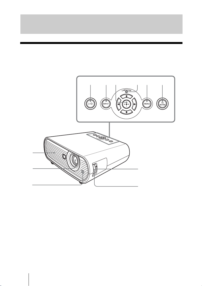
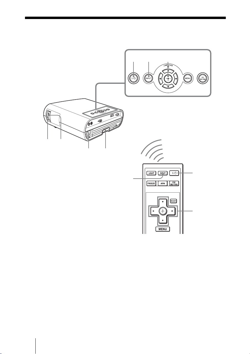
Location of Controls
q
Top/Front/Side
You can use the buttons on the control panel with the same names as those on the remote
control to operate the projector.
456 789
1
GB
2
3
0
a
6
Page 7

a Ventilation holes (exhaust)
b Lens
Remove the lens cover before
projection.
c Front remote control detector
?/1 (On/standby) switch
d
Turns on the projector when the
projector is in standby mode. To turn off
the power, press the ?/1 switch twice
according to the message or hold the ?/1
switch for about one second.
The ?/1 (On/standby) indicator lights up
or flashes under the following
conditions:
–Lights in red when the AC power cord
is plugged into a wall outlet. Once the
projector is in standby mode, you can
turn it on with the ?/1 switch.
–Flashes in red when the temperature
becomes high inside the projector, or
when the projector fails to operate.
–Lights in green when the power is
turned on, and when it is ready to
operate.
–Flashes in green until the projector is
ready to operate after the projector is
turned on. Also, flashes in green while
the cooling fan is running after the
power is turned off with the ?/1
switch. The fan runs for about 90
seconds after the power is turned off.
(1 page 27)
–Lights in orange when the power
saving mode is on.
• A reception rate of 2 flashes when the
lamp cover or air filter cover is not
secured firmly.
• A reception rate of 3 flashes when the
lamp has reached the end of its life or
reaches a high temperature.
h MENU button
Displays the on-screen menu. Press
again to clear the menu.
i PIC MUTING button
Cuts off the picture. Press again to
restore the picture.
q; Zoom ring
Adjusts the picture size.
qa Focus ring
Adjusts the picture focus.
Location of Controls
e INPUT button
Selects an input signal. The input signal
will change whenever you press the
button.
f M/m/</, (arrow) / (enter)
buttons
Used to enter the settings of items in the
menu system, select a menu, or make
various adjustments.
g LAMP/COVER indicators
Flashes in orange under the following
conditions:
GB
7
Page 8
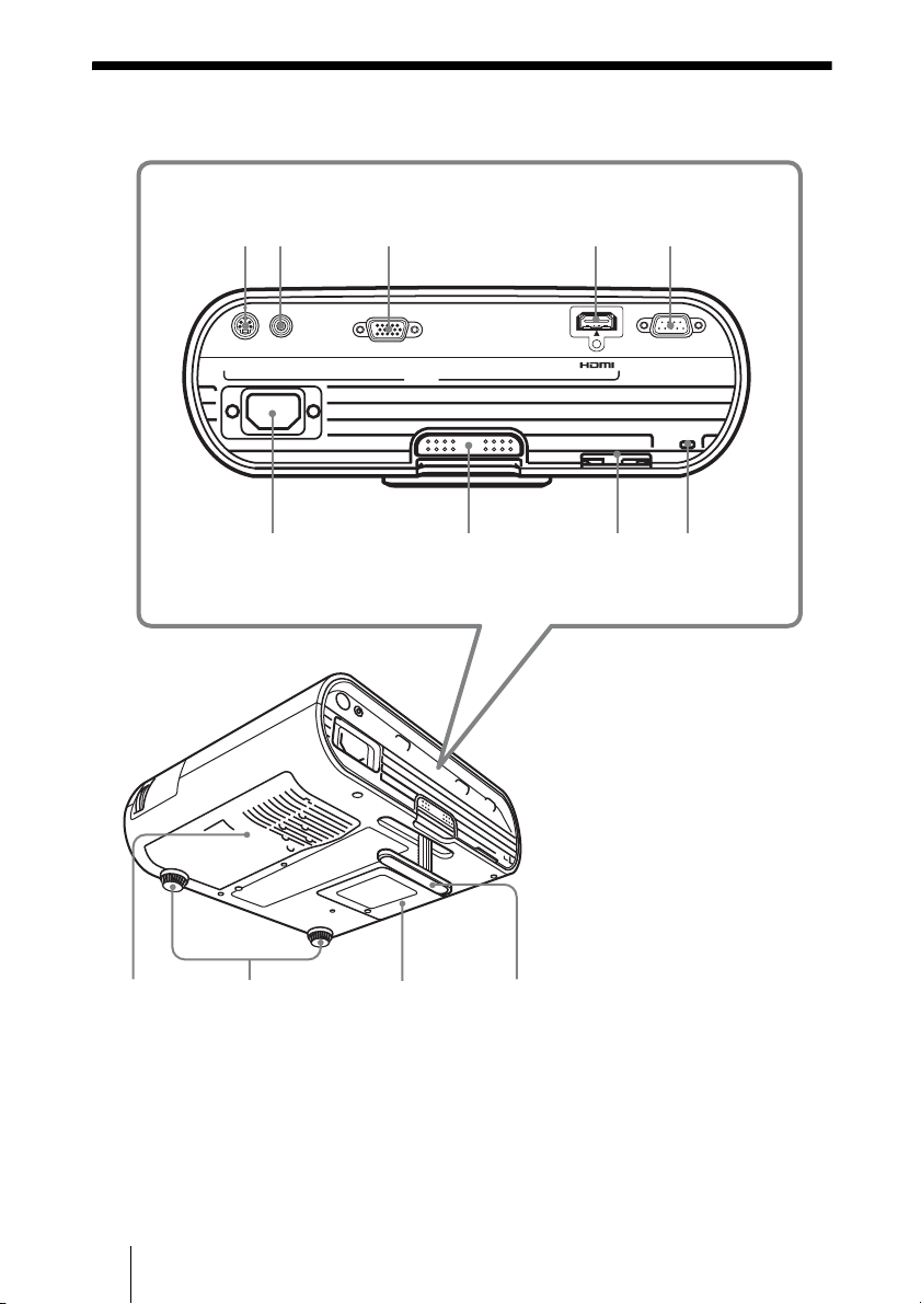
Rear/Bottom
12 34
5 6 7 8 9
S VIDEO VIDEO INPUT A
INPUT
SERVICE
0qaqsqd
GB
8
Page 9
a Ventilation holes (intake)/Air
filter cover
b Adjusters (fore pad)
c Lamp cover
d Adjuster
Adjusts the picture position. (1 page
23)
e S VIDEO INPUT connector (mini
DIN 4-pin)
Connects to the S video output of video
equipment.
f VIDEO INPUT connector (phono
type)
Connects to the video output of video
equipment.
g INPUT A connector (HD D-sub
15-pin, female)
Inputs a computer signal, video GBR
signal, component signal, or DTV signal
depending on the connected equipment.
Connects to the output connector of
equipment using the supplied cable or an
optional cable.
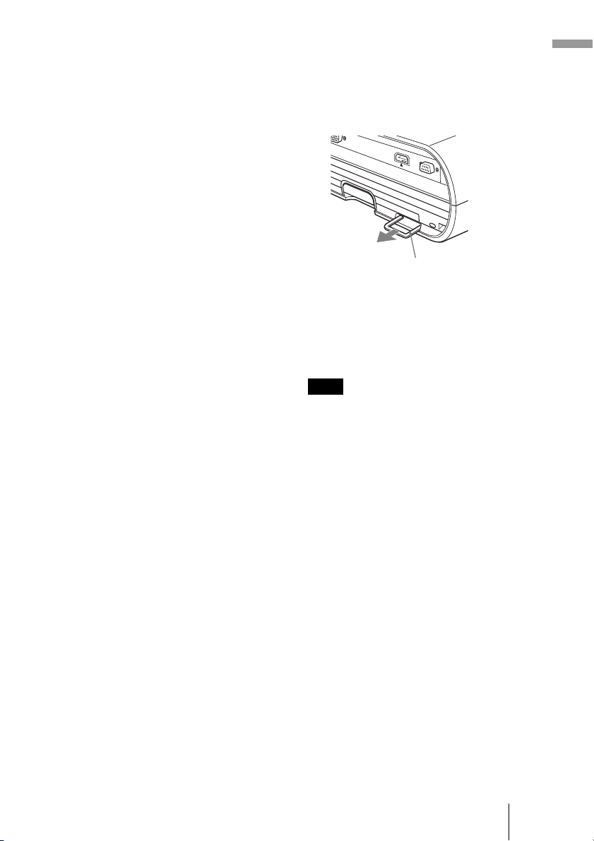
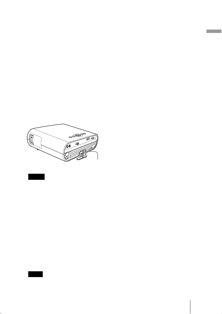
l Security bar
An anti-theft chain or wire
(commercially available) can be
connected to this bar.
If it is difficult to pull out, pull out the
security bar using a screwdriver.
Security bar
m Security lock
Connects to an optional security cable
(from Kensington).
Web page address:
http://www.kensington.com/
Note
To maintain optimal performance, clean the
air filter whenever you replace the lamp. (1
page 51)
Location of Controls
h HDMI connector
Connects to the video output connector
of the video equipment or the computer
equipped with HDMI/DVI output
connector (digital).
i SERVICE RS-232C connector
(D-sub 9-pin, female)
Used for service only.
This is not for customers’ use.
j AC IN socket
Connects the supplied AC power cord.
k Adjuster adjustment button
Press to pull out the adjuster. (1 page
23)
GB
9
Page 10
Remote Control
9
1
2
3
4
5
6
7
8
0
qa
qs
qd
qf
qg
GB
10
Page 11

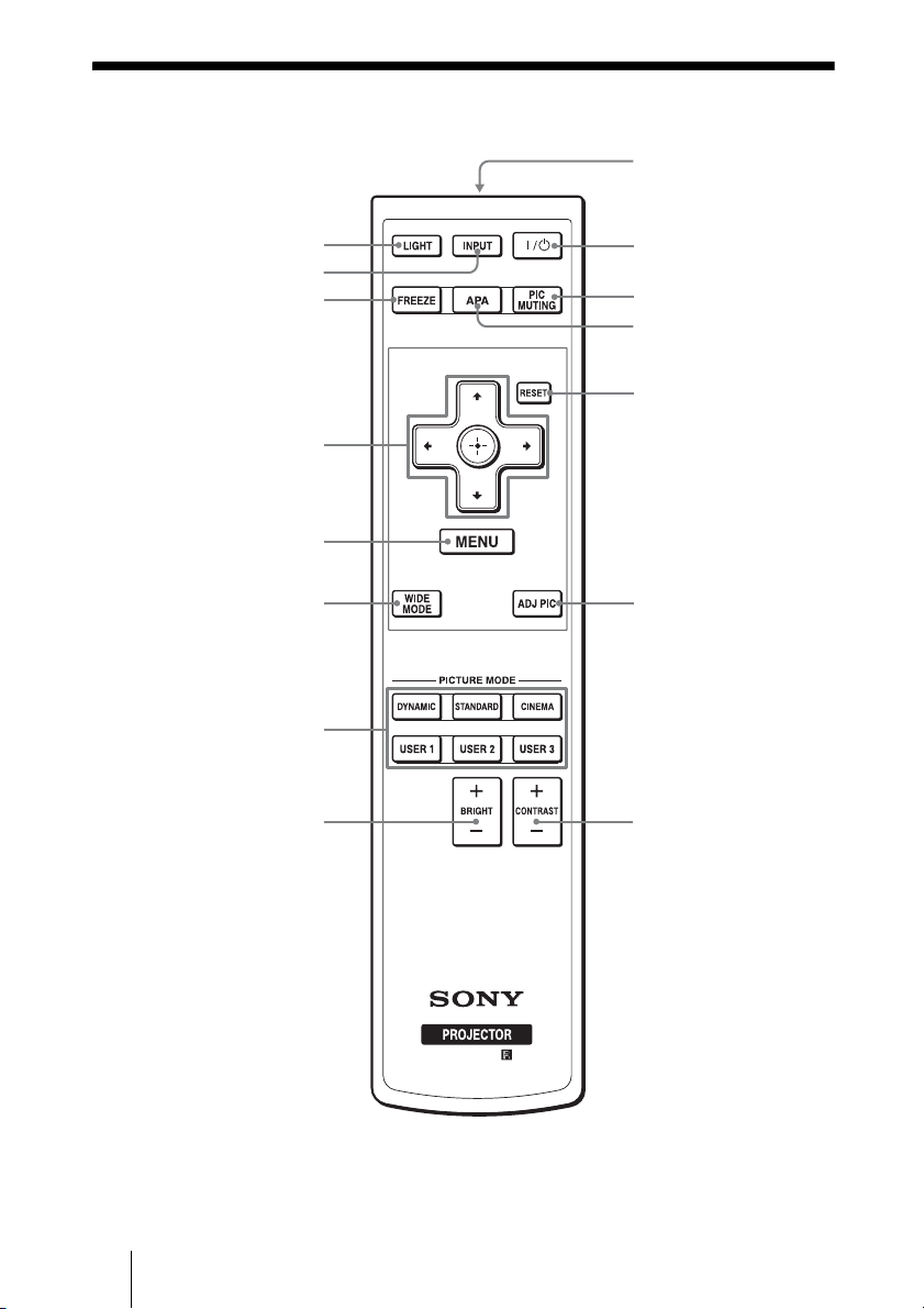
a LIGHT button
Illuminates the buttons on the remote
control.
b INPUT button
c FREEZE key
Freezes the projected picture. To cancel
the frozen picture, press the button
again.
d M/m/</, (arrow)/ (enter)
buttons
e MENU button
f WIDE MODE button
Changes the wide screen modes
according to the video signal received.
g PICTURE MODE buttons
Selects the picture viewing mode that
best suits the type of picture or the
environment.
h BRIGHT +/– button
Adjusts the brightness of the picture.
i Infrared transmitter
Adjusts the white area of pictures (white
level).
Location of Controls
?/1 (On/standby) switch
j
k PIC MUTING button
Cuts off the picture. Press again to
restore the picture.
l APA (Auto Pixel Alignment)
button
Automatically adjusts a picture to its
clearest while a signal is input from a
computer. (1 page 39)
m RESET button
Resets the value of an item to its factory
preset value. This button functions when
the menu or a setting item is displayed
on the screen.
n ADJ PIC button
Adjusts the picture quality by selecting
the adjustment items.
o CONTRAST +/– button
11
GB
Page 12
Connections and Preparations
This section describes how to install the projector and screen, how to connect the
equipment from which you want to project the picture, etc.
Unpacking
Check the carton to make sure it contains the following items:
• Remote control (1) and
Size AA (R6) batteries (2)
• AC power cord (1)
• Lens cap (1)
When you have purchased the projector,
the lens cap was fitted onto the lens.
Remove this lens cap when you use the
projector.
• Signal cable (HD D-sub 15-pin y 3 ×
phono plug) (1)
(9-885-125-47, SONY)
• Operating Instructions (this manual)
• Warranty card (1)
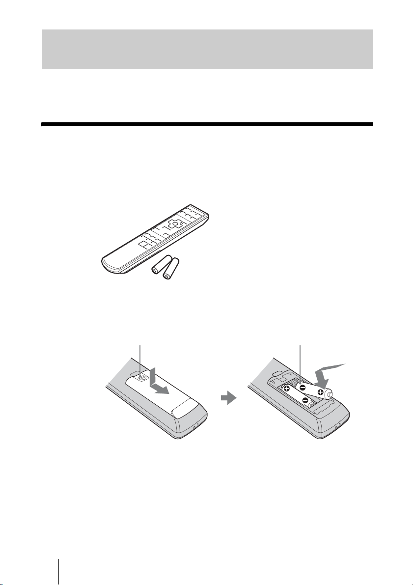
Inserting the batteries into the remote control
Insert the batteries E side first as shown in the illustration.
Inserting them forcibly or with the polarities reversed may
Push and slide to open.
Caution about handling the remote control
• Handle the remote control with care. Do not drop or step on it, or spill liquid of any kind
onto it.
• Do not place the remote control in a location near a heat source, a place subject to direct
sunlight, or a damp room.
cause a short circuit and may generate heat.
GB
12
Page 13
Step 1: Installing the Projector
The projector displays pictures output from
a VCR or other devices.
The projector can be used in various places
and you can enjoy viewing beautiful pictures
easily.
Before Setting Up the
Projector
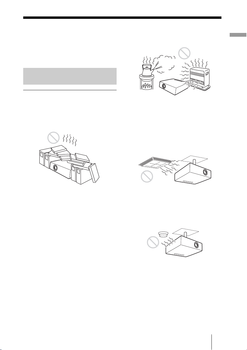
Unsuitable installation
Do not place the projector in the following
situations, which may cause malfunction
or damage to the projector.
Poorly ventilated location
• Allow adequate air circulation to prevent
internal heat build-up. Do not place the
unit on surfaces (rugs, blankets, etc.) or
near materials (curtains, draperies) that
may block the ventilation holes. When
internal heat builds up due to blockage of
ventilation holes, the temperature sensor
will function, and the power will be turned
off automatically.
• Leave space of more than 30 cm (11
inches) around the unit.
• Be careful not to allow the ventilation
holes to inhale tiny objects such as pieces
of paper or clumps of dust.
7
/8
Hot and humid
• Avoid installing the unit in a location
where the temperature or humidity is very
high, or the temperature is very low.
• To avoid moisture condensation, do not
install the unit in a location where the
temperature may rise rapidly.
Locations subject to direct cool or
warm air from an air-conditioner
Installing the projector in such a location
may cause a malfunction of the unit due to
moisture condensation or rise in
temperature.
Near a heat or smoke sensor
Malfunction of the sensor may occur.
Connections and Preparations
13
GB
Page 14
Very dusty and extremely smoky
locations
Do not block the ventilation holes
Avoid installing the unit in a very dusty or
extremely smoky environment. Otherwise,
the air filter will become obstructed, and this
may cause a malfunction of the unit or
damage it. Dust preventing the air passing
through the filter may cause a rise in the
internal temperature of the unit. Clean the air
filter whenever you replace the lamp.
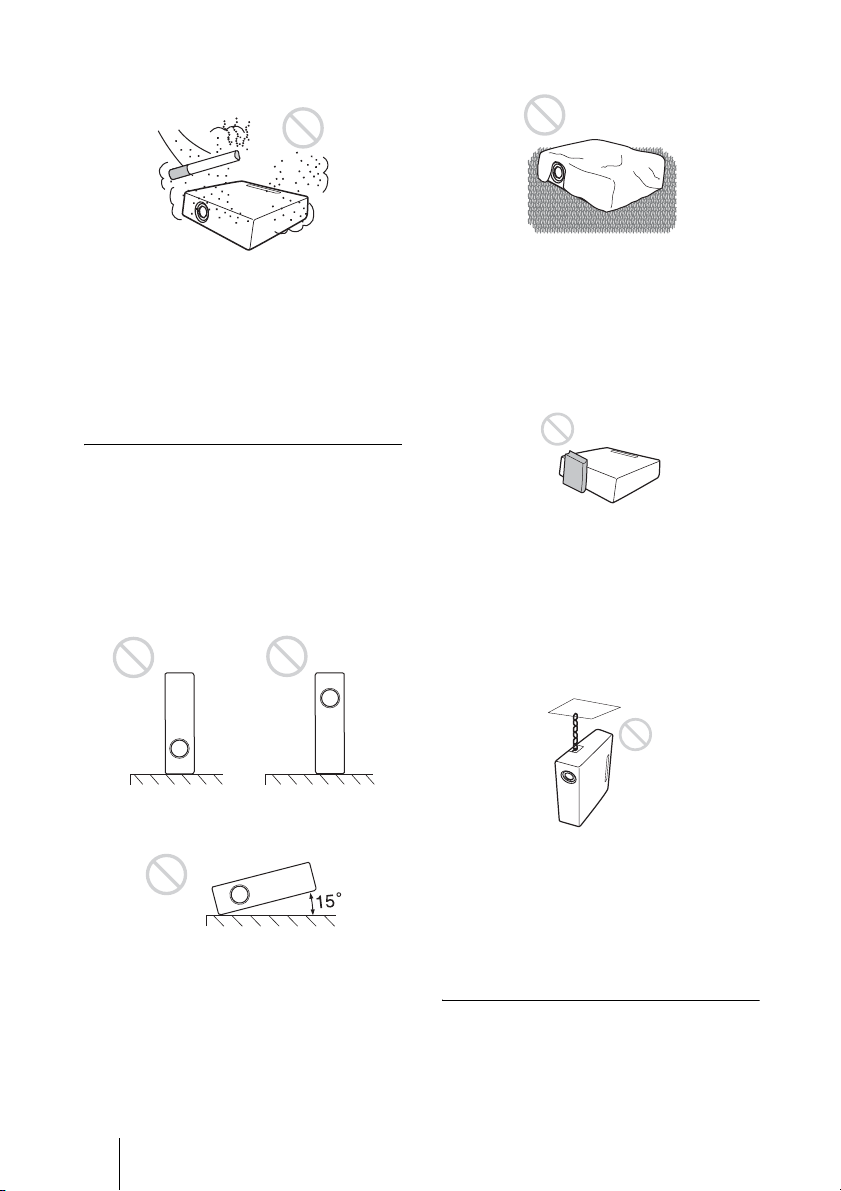
Unsuitable conditions
Do not use the projector under the
following conditions.
Do not stand the unit upright on one
side
Avoid using the unit standing upright on its
side. It may cause malfunction.
Do not tilt the unit to the right or left
Avoid tilting the unit to an angle of 15°, and
avoid installing the unit in any way other
than placing it on a level surface or
suspending from the ceiling. Such an
installation may cause color shading or
shorten the lamp life excessively.
Avoid using a thick-piled carpet or anything
that covers the ventilation holes (exhaust/
intake); otherwise, internal heat may build
up.
Do not place a blocking object just in
front of the lens
Do not place any object just in front of the
lens that may block the light during
projection. Heat from the light may damage
the object. Use the PIC MUTING button to
cut off the picture.
Do not use the security bar for
transporting or installation
Use the Security bar at the rear of the
projector for a purpose of preventing theft,
by attaching a commercially available theft
prevention cable for example. If you lift the
projector by holding the Security bar, or
hang the projector by using this bar, it may
cause the projector to fall or be damaged.
Usage at high altitude
When using the projector at an altitude of
1,500 m or higher, turn on “High
Altitude Mode” in the INSTALL SETTING
menu. Failing to set this mode when using
GB
14
Page 15

the projector at high altitudes could have
adverse effects, such as reducing
the reliability of certain components.
Connections and Preparations
15
GB
Page 16
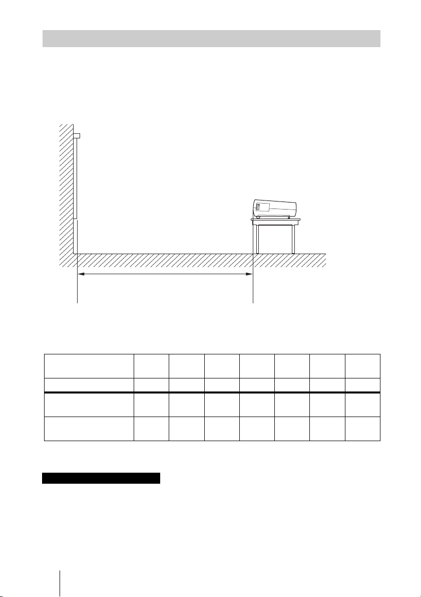
Positioning the Projector and a Screen
The installation distance between the projector and a screen varies depending on the size
of the screen.
1 Determine the installation position of the projector and screen.
Side view
Screen
Distance between the screen and
the center of the lens
* Adjuster not stretched, and the V Keystone function has been done.
When “Wide Mode” in the INPUT SETTING menu is set to “Full 2”
Unit: m (feet)
Projected image size
(diagonal) (inches)
(mm) 1016 2032 2540 3810 5080 6350 7620
Minimum Distance 1.2
Maximum Distance 1.5
40 80 100 150 200 250 300
(3.9)
(4.9)
2.5
(8.2)
2.9
(9.5)
3.1
(10.2)
3.7
(12.1)
4.6
(15.1)
5.6
(18.4)
6.2
(20.3)
7.4
(24.3)
7.7
(25.3)
9.3
(30.5)
(30.5)
(36.4)
There may be a slight difference between the actual value and the design value shown in
the table above.
Notes on Wide Mode settings
• When “Wide Mode” in the INPUT SETTING menu is set to the mode other than “Full 2”, black
bands may appear at the top and bottom or right and left of the screen.
• When “Wide Mode” in the INPUT SETTING menu is set to “4:3”, the projected image size
(diagonal) will be approximately 88% of “Full 2” size.
• When “Wide Mode” in the INPUT SETTING menu is set to “16:9”, the projected image size
(diagonal) will be approximately 97% of “Full 2” size.
For details on installation, see “Installation Diagram” on page 56.
GB
16
9.3
11.1
Page 17
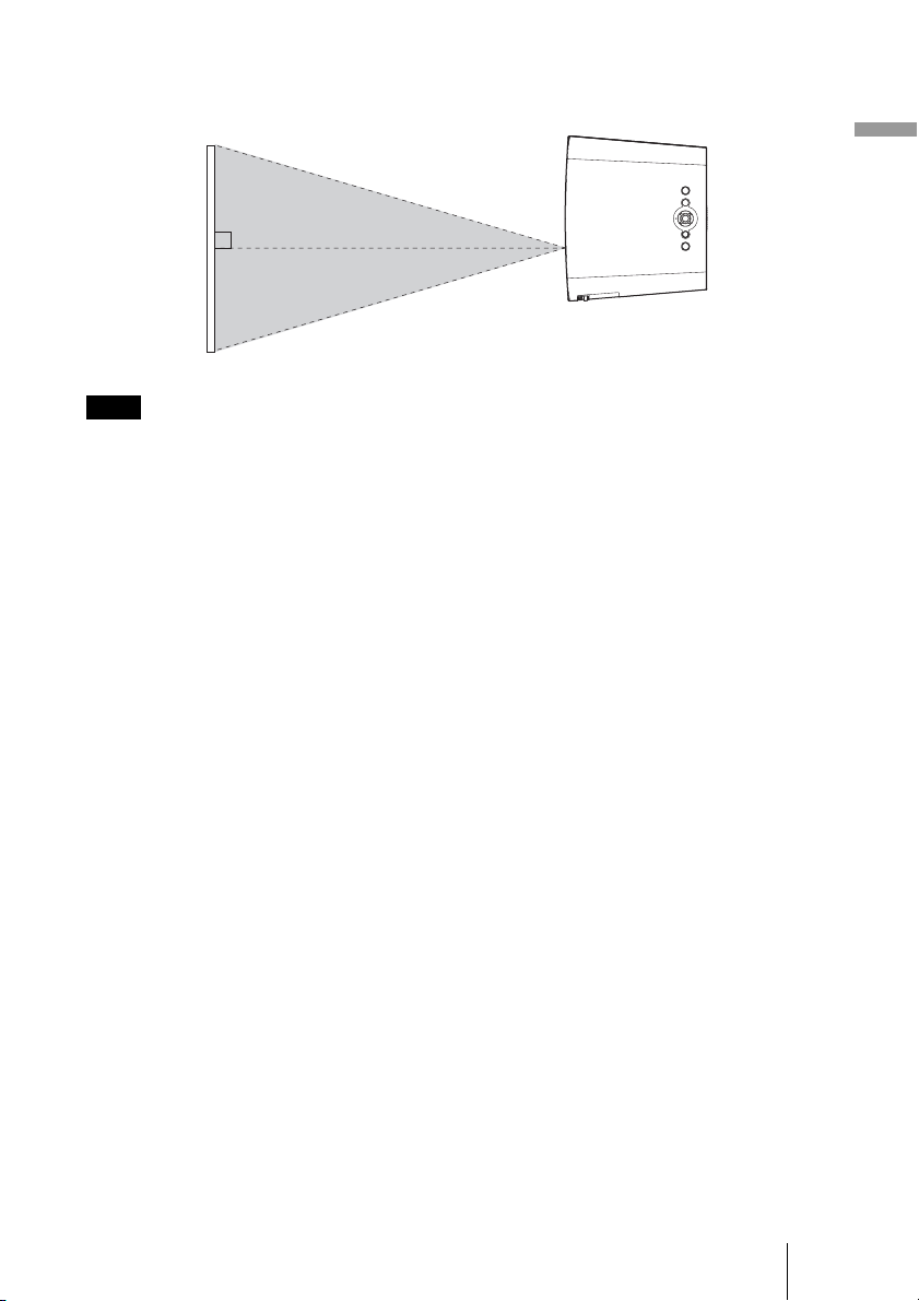
2 Position the projector so that the lens is parallel to the screen.
Top view
Screen
Note
When using a screen with an uneven surface, stripes pattern may rarely appear on the screen
depending on the distance between the screen and the projector or the zooming magnifications. This
is not a malfunction of the projector.
Connections and Preparations
17
GB
Page 18
Step 2: Connecting the Projector
When making connections, be sure to do the following:
• Turn off all equipments before making any connections.
• Use the proper cables for each connection.
• Insert the cable plugs properly; poor connection at the plugs may cause a malfunction or
poor picture quality. When pulling out a cable, be sure to pull it out with holding the
plug, not the cable itself.
• Refer to the operating instructions of the connected equipment.
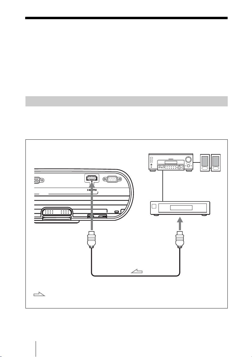
Connecting to a VCR
To connect to a DVD player/recorder and Blu-ray Disc player equipped with
HDMI output
You can enjoy better picture quality by connecting a DVD player/recorder and Blu-ray
Disc player equipped with HDMI output to the HDMI input of the projector.
Rear of the projector
T A
INPUT
: Video signal flow
AV amplifier
SERVICE
to HDMI output
HDMI cable (not supplied)
When using an optional HDMI cable, be sure to use
a cable that has acquired an HDMI logo.
DVD player/recorder and
Blu-ray Disc player, etc.,
with the HDMI output
Speakers
............................................................................................................................................................
This projector supports PC Display input of HDMI. It also supports HDCP.
GB
18
Page 19
Notes
• When connecting equipment to the HDMI input of the projector, be sure to use equipment that
have acquired the HDMI logo.
• When connecting an HDMI cable to the projector, make sure the
HDMI input of the projector and the
v mark on the connector of the cable is set at the same
v mark on the lower part of the
position.
• If the picture from equipment connected to the projector with an HDMI cable is not clear, check
the settings of the connected equipment.
• The HDMI connector of this projector is not compatible with DSD (Direct Stream Digital) Signal
or CEC (Consumer Electronics control) Signal.
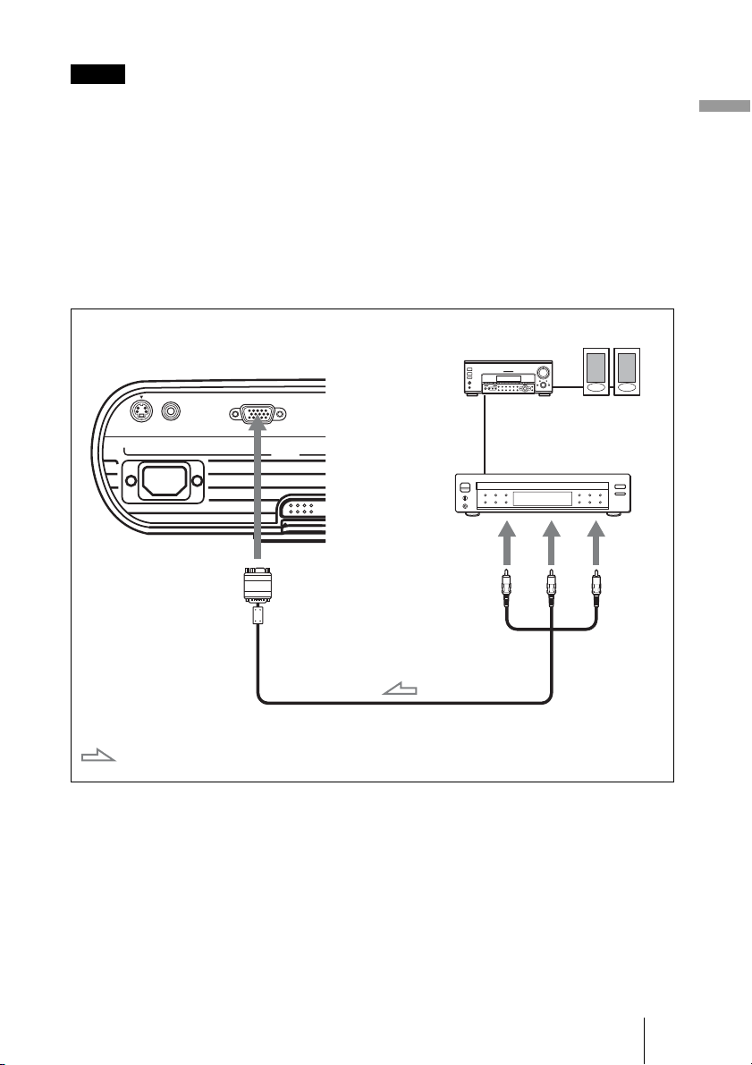
To connect to a DVD player/recorder, Blu-ray Disc player or digital tuner
equipped with a video GBR/component video connectors
Connections and Preparations
Speakers
Rear of the projector
S VIDEO VIDEO INPUT A
: Video signal flow
AV amplifier
DVD player/recorder, HDD
recorder, Blu-ray Disc player,
digital tuner, etc., with video
INPUT
to video GBR or
component
output
Signal cable (HD D-sub 15-pin (male) y 3 × phono plug)
(supplied)
GBR/component video
connectors
• Set the aspect ratio by pressing WIDE MODE on the remote control or using “Wide
Mode” in the INPUT SETTING menu according to the input signal.
• When you connect the projector to a video GBR output connector, select “Video GBR”
or when you connect the projector to component output connectors, select “Component”
with the “Input-A Signal Sel.” setting in the SET SETTING menu.
19
GB
Page 20
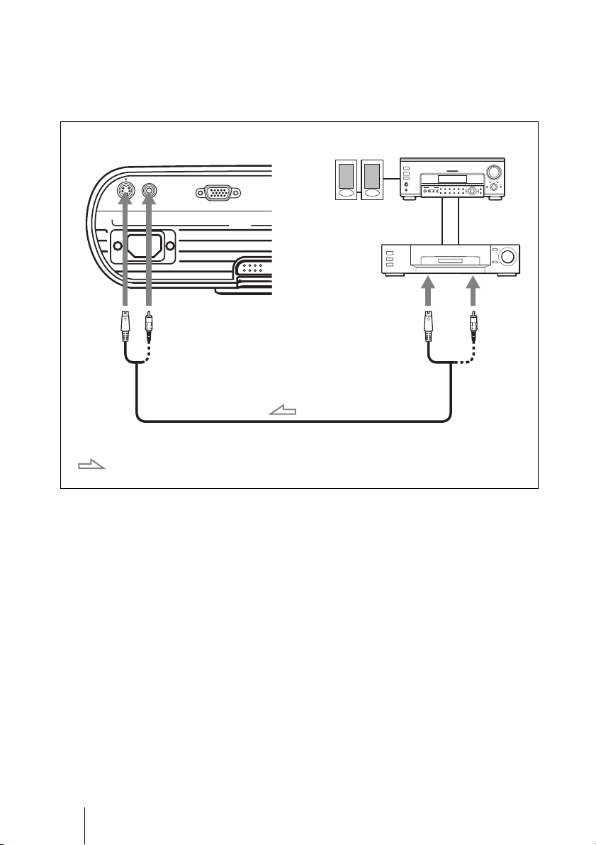
To connect to a VCR equipped with the S video connector or video
connector
You can connect a DVD player/recorder, hard disk video recorder, VCR or laser disk
player, which is not equipped with component video connectors. See also the instruction
manual of each equipment.
Rear of the projector
S VIDEO VIDEO INPUT A
: Video signal flow
INPUT
S video or video cable (not supplied)
Video equipment
to S video or
video output
AV amplifierSpeakers
Tip
In order to enjoy better video performance, use S Video connector.
If the equipment to be connected has no S video connector, connect the cable to the video output.
GB
20
Page 21
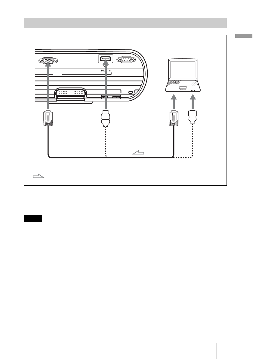
Connecting to a Computer
Rear of the projector
Computer
INPUT A
INPUT
HD D-sub15-pin cable (not supplied) or HDMI-DVI-D cable
(not supplied)
: Video signal flow
SERVICE
to monitor
output
to DVI-D
output
Tip
Set “Input-A Signal Sel.” in the SET SETTING menu to “Auto” or “Computer.” If the input signal
does not appear properly, set it to “Computer.” (1 page 39)
Connections and Preparations
Notes
• The projector accepts VGA, SVGA, XGA, SXGA, SXGA+, WXGA signals. However, we
recommend that you set the output mode of your computer to WXGA mode for the external
monitor.
• To connect a Macintosh computer equipped with a video output connector of a type having two
rows of pins, use a commercially available plug adaptor.
• If you set your computer, such as a notebook type, to output the signal to both computer’s display
and the external monitor, the picture of the monitor may not appear properly. Set your computer
to output the signal only to the external monitor.
For details, refer to the computer’s operating instructions supplied with your computer. For
settings of the computer, consult with the manufacturer of the computer.
• The HDMI connector of this projector is not compatible with DSD (Direct Stream Digital) Signal
or CEC (Consumer Electronics control) Signal.
• When connecting an HDMI cable to the projector, make sure the
HDMI input of the projector and the
v mark on the connector of the cable is set at the same
v mark on the lower part of the
position.
21
GB
Page 22
Step 3: Adjusting the Picture Position
Project an image on the screen and adjust the picture position.
1,2 4
6
78
15
2
4
6
1 After connecting the AC cord to
the projector, plug the AC cord
into a wall outlet, connect all
equipment, and remove the lens
cover.
The ?/1 (On/standby) switch lights in
red and the projector goes into standby
mode.
2 Press the ?/1 (On/standby)
switch to turn on the projector.
The ?/1 (On/standby) switch flashes in
green, then lights in green.
GB
22
3 Turn on the equipment
connected to the projector.
Refer to the operating instructions of the
connected equipment.
4 Press INPUT to project the
picture on the screen.
Each time you press the button, the input
indication and equipment to be projected
change. (1 page 27)
Page 23
Tips
• You can select the desired language for the
menu screen. For details, refer to “Step 4:
Selecting the Menu Language”. (1 page 24)
• When “Auto Input Search” is set to “On” in
the SET SETTING menu, the input terminal
with effective signals is automatically
displayed by pressing INPUT. (1 page 39)
5 Adjust the upper or lower
position of the picture.
Use the adjuster to adjust the picture
position.
Using the adjuster
Lift the projector while pressing the
adjuster adjustment button, and adjust
the tilt of the projector, then release the
button to lock the adjuster.
Adjuster adjustment button
adjusted depending on the room
temperature or the tilt of the screen. In this
case, adjust it manually.
7 Adjust the picture size using the
zoom lever.
8 Adjust the focus using the focus
ring.
Connections and Preparations
Notes
• Be careful not to let the projector down
on your fingers.
• Do not push hard on the top of the
projector or do not drag it hard with the
adjuster out. It may cause malfunction.
6 Adjust the trapezoidal distortion
of the picture.
The V Keystone adjustment is
performed automatically when you
adjust the tilt of the projector with the
adjuster. If you do not want to perform
the keystone adjustment automatically,
set “V Keystone” in the INSTALL
SETTING menu to “Manual.” (1 page
42)
Note
If you set “V Keystone” to “Auto,” the V
Keystone correction is automatically
adjusted. However, it may not be perfectly
23
GB
Page 24
Step 4: Selecting the Menu Language
You can select one of 17 languages for displaying the menu and other on-screen displays.
The factory default setting is English. To change the current menu language, set the
desired language with the menu screen.
2,3,4 1
GB
2,3,4
1
24
Page 25
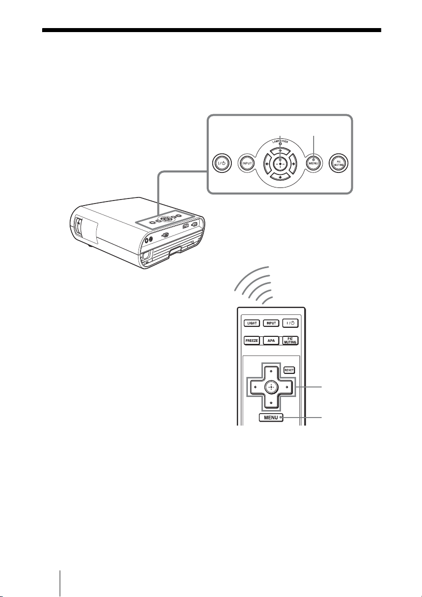
1 Press MENU.
The menu appears.
The menu currently selected is shown as
a yellow button.
2 Press M/m to select the MENU
SETTING menu, and press .
The setting items of the selected menu
appears.
Connections and Preparations
3 Press M/m to select “Language,”
and press .
4 Press M/m/</, to select a
language, and press .
The menu changes to the selected
language.
To clear the menu
Press MENU.
The menu disappears automatically if a
button is not pressed for one minute.
25
GB
Page 26
Projecting
This section describes how to operate the projector to view the picture from the equipment
connected to the projector. It also describes how to adjust the quality of the picture to suit
your taste.
Projecting the Picture on the Screen
1,2 4
1
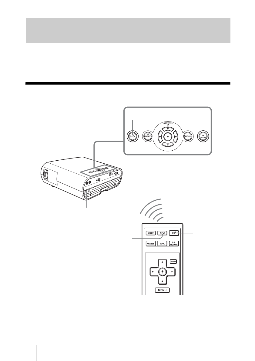
1 After connecting the AC cord to
the projector, plug the AC cord
into a wall outlet, connect all
equipment, and remove the lens
cover.
GB
26
4
2
The ?/1 (On/standby) switch lights in
red and the projector goes into standby
mode.
2 Press the ?/1 (On/standby)
switch to turn on the projector.
Page 27
The ?/1 (On/standby) switch flashes in
green, then lights in green.
The projector cannot be used while the
?/1 switch is flashing.
3 Turn on the equipment
connected to the projector.
Refer to the operating instructions of the
connected equipment.
changing your computer’s settings.
The key used for switching the computer
to output to the projector varies
depending on the type of computer.
or
F7
and
Fx
Projecting
4 Press INPUT repeatedly to
select the input you want to
project on the screen.
Each time you press the button, you can
select the input in the following
sequence.
Input-A t HDMI t Video t S-Video
To view the picture from Press INPUT
Computer/Component
connected to the INPUT
A connector
Computer/VCR, etc.
connected to HDMI
(digital) connector
Video equipment
connected to the VIDEO
INPUT connector
Video equipment
connected to the
S VIDEO INPUT
connector
Notes
• If “Auto Input Search” is set to “On,” the
projector searches for the signals from
the connected equipment and displays
the input channel where the input signals
are found. (1 page 39)
• When the analog signal is input from a
computer, the Smart APA (Auto Pixel
Alignment) feature adjusts the picture of
the connected equipment to its clearest.
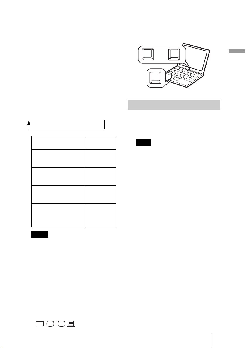
• Depending on the type of your computer,
for example a notebook, or an all-in-one
LCD type, you may have to switch the
computer to output to the projector by
pressing certain keys (e.g.,
VGA
LCD
//
,
to display
Input-A
HDMI
Vid eo
S-Video
, etc.), or by
Fn
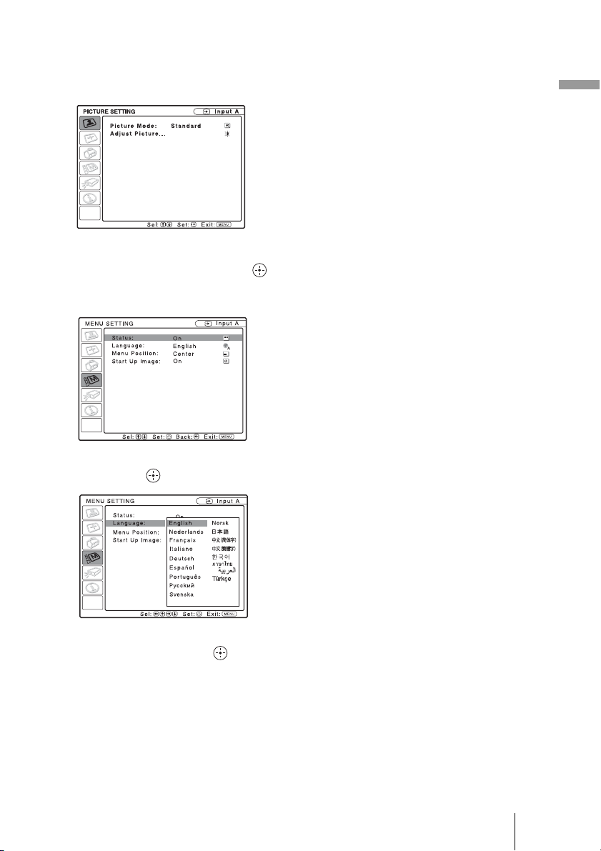
Turning Off the Power
1 Press the ?/1 switch.
A message “POWER OFF? Please press
?/1 key again.” appears on the screen.
Note
The message disappears if you press any
button other than the
do not press any button for five seconds.
?/1 switch, or if you
2 Press the ?/1 switch again.
The ?/1 switch flashes in green and the
fan continues to run to reduce internal
heat. Also, the ?/1 switch flashes
quickly for the first 60 seconds. During
this time, you will not be able to light up
the ?/1 switch again with this switch.
3 Unplug the AC power cord from
the wall outlet after the fan stops
running and the
?/1 switch
lights in red.
27
GB
Page 28
Selecting the Wide Screen Mode
You can enjoy various wide screen modes according to the video signal received.
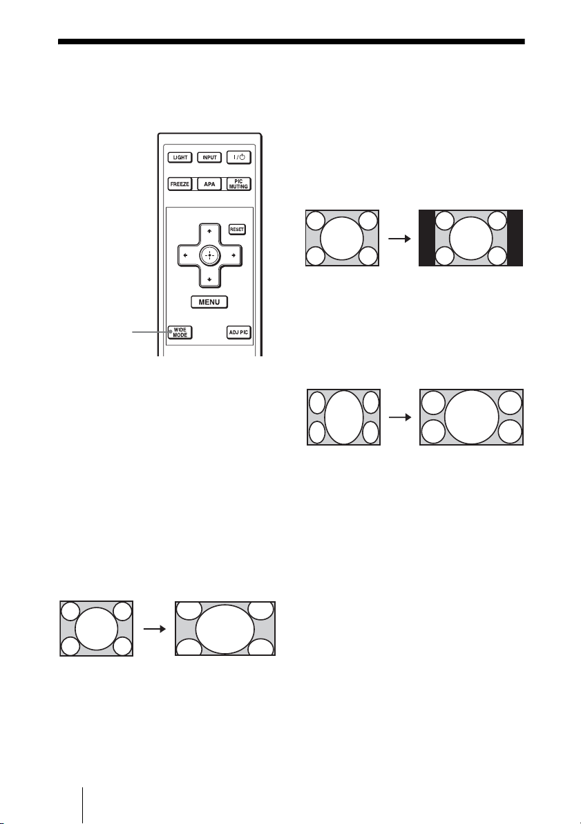
Normal
A picture with normal 4:3 aspect ratio is
displayed in the center of the screen to fill
the vertical screen size.
WIDE MODE
button
Press WIDE MODE.
Each time you press the button, you can
change the “Wide Mode” setting in turn.
You can also select it using the menu. (1
page 37)
Wide Zoom (When the SD signal is
input)
A 4:3 aspect ratio picture is enlarged over
the entire screen properly. The upper and
lower portions of the screen are slightly cut
off.
Original image When the Wide
Mode is operated
Original image When the Wide
Full
A picture squeezed to 4:3 is displayed with
the correct aspect ratio. A 4:3 picture is
enlarged horizontally to fit the 16:9 screen.
Original image When the Wide
Squeezed
Tip
Squeezed: An original 16:9 aspect ratio picture
is recorded horizontally compressed to a 4:3
picture.
Mode is operated
Mode is operated
GB
28
Page 29
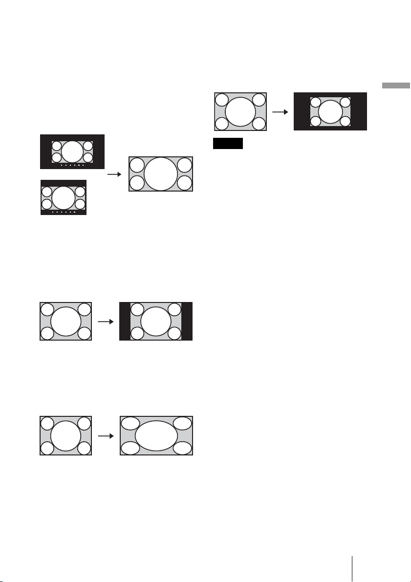
Zoom (When the SD or PC signal is
input)
A normal 16:9 aspect ratio picture is
enlarged vertically and horizontally in the
same ratio to fill the screen. Use this mode to
view a letterbox picture or a letterbox picture
with side panels.
Original image
Letterbox picture
with side panels
Letterbox picture
When the Wide
Mode is operated
Full 1 (When the PC signal is input)
Displays a picture on the whole of the screen
without changing the aspect ratio of the
original picture.
Original image When the Wide
Mode is operated
Full 3 (When the PC signal is input)
Displays a 1280 × 720 dot picture on the
screen without changing the aspect ratio of
the original picture.
Original image When the Wide
Mode is operated
Projecting
Notes
• Changing the aspect ratio of the original
picture will provide a different look from
that of the original image.
• Note that if the projector is used for profit
or for public viewing, modifying the
original picture by switching to the wide
mode may constitute an infringement of
the rights of authors or producers, which
are legally protected.
Full 2 (When the PC signal is input)
Displays a picture on the whole of the
screen.
Original image When the Wide
Mode is operated
29
GB
Page 30
Selecting the Picture Viewing Mode
You can select the picture viewing mode that best suits the type of program or room
conditions.
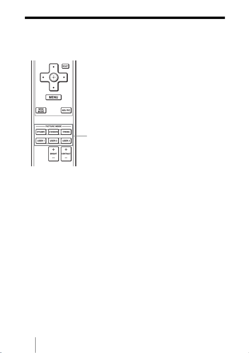
Press one of the PICTURE MODE
buttons (DYNAMIC, STANDARD,
CINEMA and USER 1, USER 2 and
USER 3).
DYNAMIC
The picture becomes bright suitable for
viewing the picture in a bright room.
PICTURE
MODE buttons
DYNAMIC
STANDARD
CINEMA
USER 1,
USER 2 and
USER 3
STANDARD
The quality of the picture becomes more
natural than the one selected by
“DYNAMIC.”
CINEMA
Recommended when viewing a movie in a
dark place.
USER 1, USER 2 and USER 3
You can adjust the quality of the picture to
suit your taste and store the settings into
the selected memory of the projector.
Press one of the USER 1, USER 2 and
USER 3 buttons, then adjust the picture
by using the buttons on the remote control
or the menus. (1
pages 31 and 35)
The settings are stored, and you can view
the picture with the adjusted picture
quality by pressing the button.
GB
30
Page 31

Adjusting the Picture Quality
You can adjust the picture quality that suits your taste by selecting the adjustment items
with the remote control. The adjusted data can be stored in each picture mode.
ADJ PIC button
1 Press ADJ PIC.
Each time you press the button, the
following adjustment windows* are
displayed in sequence.
* Some of the adjustment windows will
not be displayed depending on the
input signal. For details, see “Input
Signals and Adjustable/Setting
Items.” (1 page 45)
Contrast
Brightness
Color
Hue
Sharpness
Gamma Mode
Color Temp.
DDE
For details on each adjustment, see the
PICTURE SETTING menu. (1 page
35)
2 Make the setting or adjustment
on an item.
When changing the adjustment
level
To increase the value, press ,.
To decrease the value, press <.
When changing the setting
Press M/m to change the setting.
Projecting
31
GB
Page 32

Using Other Functions
You can temporarily turn off or pause a projected picture.
Press PIC MUTING.
Press to temporarily turn off a projected
picture. To return to the previous screen,
press PIC MUTING again.
PIC MUTING
button
FREEZE
button
Press FREEZE.
A projected picture can be paused to be
displayed. “FREEZE” is shown on the
screen when a button is pressed. To return to
the previous screen, press FREEZE again.
Note
The FREEZE function is available for only
computer signal.
GB
32
Page 33

Using the Menus
This section describes how to make various adjustments and settings using the menus.
Operation through the Menus
The projector is equipped with an on-screen menu for making various adjustments and
settings. Some of the adjustable/setting items are displayed in a pop-up menu, in an
adjustment menu with no main menu, or in the next menu window. If you select an item
name followed by dots (···), the next menu window with setting items appears.
To change the on-screen menu language, see “Step 4: Selecting the Menu Language”.
(1 page 24)
Input signal setting indicator
When Input-A is selected: Shows “Auto”
or “Input-A Signal Sel.” setting in the SET
SETTING menu.
When Video or S-Video is selected: Shows
“Auto” or the “Color System” setting in the
SET SETTING menu.
RESET
button
2,3,4
1
Display items
The input signal and input signal setting
indicators are displayed on the upper right
corner of the menu window.
1 Press MENU.
The menu window appears.
The menu presently selected is shown as
a yellow button in the column on the left.
SET SETTING
Smart APA: On
Auto Input Search:
Input-A Signal Sel.: Component
Color System: Auto
Power Saving: Off
CC Display: Off
Lamp Timer Reset
Off
Input-A
Using the Menus
Input signal indicator
Input signal setting indicator
Input signal indicator
Shows the selected input channel. is
x
displayed when no signal is input. You can
hide this indicator using “Status” in the
MENU SETTING menu.
2 Press M/m to select a menu, and
press , or .
The items that can be set or adjusted
with the selected menu appear.
3 Press M/m to select an item you
want to set or adjust and press ,
or .
The items that can be set appear in the
pop-up menu, adjustment menu, or in
the next menu window.
33
GB
Page 34

Pop-up menu
Setting itemsMenu
MENU SETTING
Status:
Language:
Menu Position:
Start Up Image
Adjustment menu
Next menu window
PICTURE SETTING
ADJUST PICTURE
Contrast: 80
Brightness: 50
Gamma Mode: Off
Color Temp.: High
On
English
Top left
Bottom Left
Center
Top Right
Bottom Right
Setting itemsMenu
Standard
Input A
Input A
To clear the menu
Press MENU.
The menu disappears automatically if a
button is not pressed for one minute.
A
To reset the items that have been
adjusted
Select an item that you want to reset, then
press RESET on the remote control.
The message “Complete!” appears on the
screen and the setting of the item that you
have selected is reset to its factory preset
value.
Items that can be reset are:
• “Contrast,” “Brightness,” “Color,” “Hue”
and “Sharpness” in the “Adjust Picture...”
menu of the PICTURE SETTING menu
• “Dot Phase,” “H Size,” and “Shift” in the
“Adjust Signal...” menu of the INPUT
SETTING menu
Storage of the settings
The settings are automatically stored in the
projector memory when the button is
pressed.
If no signal is input
If there is no input signal, the message
“Cannot adjust this item.” appears on the
screen.
4 Make the setting or adjustment of
an item.
When changing the adjustment
level
To increase the value, press M/,.
To decrease the value, press m/<.
Press to restore the previous screen.
When changing the setting
Press M/m to change the setting.
Press to restore the previous screen.
You can restore the previous screen
using < depending on the selected
item.
Items that cannot be adjusted
Adjustable items differ depending on the
input signal. The items that cannot be
adjusted or set do not appear in the menu.
(1 page 45)
GB
34
Page 35

PICTURE SETTING Menu
The PICTURE SETTING menu is used for adjusting the picture.
PICTURE SETTING
Picture Mode Standard
Adjust Picture...
Input A
PICTURE SETTING
ADJUST PICTURE
Contrast: 80
Brightness: 50
Gamma Mode: Off
Color Temp.: High
Standard
Setting items Functions Initial setting
Picture Mode You can select the picture viewing mode that best
suits the type of picture or the environment.
Dynamic: Select this for bright picture suitable for
viewing it in a bright room.
Standard: Select this for more natural picture than
the picture with the Dynamic setting.
Cinema: Select this for watching movies, etc. in a
dark environment.
User 1, User 2, User 3: You can adjust the quality of
the picture to suit your taste and then store the
settings. Once the settings are stored, you can view
the picture with the adjusted picture quality by
pressing PICTURE MODE on the remote control.
Input-A
Set according to
the input signal
Using the Menus
To store the settings
1 Select User 1, User 2, or User 3.
2 Adjust the items you want in the menus.
Tips
• You can also adjust the picture quality in
“Dynamic”, “Standard” or “Cinema”, and store the
settings. To reset everything to the factory settings,
select “Picture Mode,” and press RESET on the
remote control.
• Some items may not be displayed in the PICTURE
SETTING menu, depending on the type of input
signal. For details, see “Input Signals and
Adjustable/Setting Items” (1 page 45).
Adjust Picture... The projector can store the setting values of the following menu items for
each picture mode separately.
Contrast Adjusts the white area of pictures (white level).
80
The higher the setting, the greater the contrast. The
lower the setting, the lower the contrast.
You can make adjustments by pressing
CONTRAST+/– on the remote control.
35
GB
Page 36

Setting items Functions Initial setting
Brightness Adjusts the brightness of the picture.
Color Adjusts the intensity of the color density.
Hue Adjusts the color tone.
Sharpness Sharpens the outline of the picture, or reduces the
Gamma
Mode
Color Temp. Adjusts the color temperature.
DDE
(Dynamic
Detail
Enhancer)
The higher the setting, the brighter the picture. The
lower the setting, the darker the picture.
You can make adjustments by pressing BRIGHT+/–
on the remote control.
The higher the setting, the greater the intensity. The
lower the setting, the lower the intensity.
The higher the setting, the more greenish the picture
becomes. The lower the setting, the more reddish the
picture becomes.
noise.
The higher the setting, the sharper the picture. The
lower the setting, the softer the picture, thus reducing
the noise.
Adjusts the response characteristics of the tone of
the picture.
Select a favorite tone from three options.
Gamma1: Makes a scene a little brighter.
Gamma2: Makes a scene brighter.
Gamma3: Makes a scene darker.
Off: Gamma Mode is “Off”.
High: Gives white colors a blue tint.
Middle: Gives a neutral tint between “High” and
“Low”.
Low: Gives white colors a red tint.
According to the film source you have selected,
make a setting for playback.
Off: Plays a video signal in an interlace format
without converting.
Progressive: Converts an interlace format video
signal to a progressive format.
Film: Normally, select this option. Reproduces the 2-
3 Pull-Down film sources with smooth picture
movement. When the video signal with a format
other than the 2-3 Pull-Down is input,
“Progressive” is automatically selected.
50
50
50
30
Off
Set according to
the input signal
Film
GB
36
Page 37

INPUT SETTING Menu
The INPUT SETTING menu is used to adjust the input signal.
When the signal is input from a computer
Adjust Signal...
Wide Mode: Normal
Over Scan: Off
Setting items Functions Initial setting
Adjust Signal...
Dot Phase Adjusts the dot phase of the LCD panel and the
signal output from a computer.
Adjust the picture further for finer picture after the
picture is adjusted by pressing the APA key.
H Size Adjusts the horizontal size of a picture output
from a computer.
Adjust the setting according to the dots of the input
signal. (1 page 54)
Shift Adjusts the position of the picture.
H: As the setting for H (horizontal) increases, the
picture moves to the right, and as the setting
decreases, the picture moves to the left. Use
</, to adjust the horizontal position.
V: As the setting for V (vertical) increases, the
picture moves up, and as the setting decreases, the
picture moves down. Use M/m to adjust the
vertical position.
Wide Mode
(When the video
signal is input)
You can set the aspect ratio of the picture to be
displayed for the current input signal. This item is
enabled only when an video signal (preset
memory numbers 1 to 11) is input.
Normal: A picture with normal 4:3 aspect ratio is
displayed in the center of the screen to fill the
vertical screen size.
Full: A picture squeezed to 4:3 is displayed with the
correct aspect ratio. A 4:3 picture is enlarged
horizontally to fit the 16:9 screen.
Zoom: A normal 16:9 aspect ratio picture (SD signal
only) is enlarged vertically and horizontally in the
same ratio to fill the screen.
Wide Zoom: A 4:3 aspect ratio picture (SD signal
only) is enlarged over the entire screen properly.
The upper and lower portions of the screen are
slightly cut off.
Set according to
the input signal
Set according to
the input signal
Set according to
the input signal
Set according to
the input signal
Using the Menus
37
GB
Page 38

Setting items Functions Initial setting
Wide Mode
(When the PC
signal is input)
Over Scan Hides the outer edges of the picture.
Notes
• Some of the “Wide Mode” setting items are not displayed on the screen according to the input
signal.
• Note that if the projector is used for profit or for public viewing, modifying the original picture by
switching to the wide mode may constitute an infringement of the rights of authors or producers,
which are legally protected.
You can set the aspect ratio of the picture to be
displayed for the current input signal. This item is
enabled only when an PC signal (preset memory
numbers 21 to 63) is input.
Full 1: Displays a picture on the whole of the screen
without changing the aspect ratio of the original
picture.
Full 2: Displays a picture on the whole of the screen.
Full 3: Displays a 1280 × 720 dot picture on the
screen without changing the aspect ratio of the
original picture.
Normal: Displays the picture while matching one
pixel of input picture element to that of the LCD.
The picture will be clear but the picture size will
be smaller.
Zoom: A normal 16:9 aspect ratio picture is enlarged
vertically and horizontally in the same ratio to fill
the screen.
On: Hides the outer edges of the input picture. Select
this setting when noise appears along the edge of
the picture.
Off: Projects the whole of the input picture.
Set according to
the input signal
On
About the Preset Memory No.
This projector has 45 types of preset data for input signals (the preset memory). When a
preset signal is input, the projector automatically detects the signal type and recalls the
data for the signal from the preset memory to adjust it to an optimum picture. The memory
number and signal type of that signal are displayed on the INFORMATION menu (1
page 44). You can also adjust the preset data through the INPUT SETTING menu.
See the chart on page 54 to find if the signal is registered in the preset memory.
Note
When the aspect ratio of input signal is other than “Full 2”, a part of the screen may be displayed in
black.
GB
38
Page 39

SET SETTING Menu
The SET SETTING menu is used for changing the settings of the projector.
SET SETTING
Smart APA: On
Auto Input Search:
Input-A Signal Sel.:
Color System: Auto
Power Saving: Off
CC Display: Off
Lamp Timer Reset
Off
Auto
Setting items Functions Initial setting
Smart APA The APA (Auto Pixel Alignment) automatically
Auto Input Search Detects the input signal and displays the detected
Input-A Signal
Sel.
Color System Selects the color system of the input signal.
Input-A
adjusts “Dot Phase,” “H Size” and “Shift” in the
INPUT SETTING menu for the input signal from
a computer.
On: When a signal is input from a computer, the
APA functions automatically so that the picture
can be seen clearly. You can adjust the picture by
pressing APA on the remote control even if “Smart
APA” is set to “On.”
Off: APA functions only when you press APA on the
remote control.
input signal automatically when the INPUT
button is pressed.
When set to “On,” the projector detects input signals
in the following order: Input-A, HDMI, Video and SVideo. It indicates the input channel when the power
is turned on or the INPUT button is pressed.
Selects the type of signal input from the
equipment connected to the INPUT A connector.
Selects the type of signal input from the equipment
by selecting “Input-A” with the INPUT button.
Auto: Selects the input signal type automatically.
Computer: Inputs the signal from a computer.
Component: Inputs the component signal from a
DVD player/recorder, Blu-ray Disc player, digital
tuner, etc.
Video GBR: Inputs the signal from a TV game or
HDTV broadcast.
If you select “Auto,” the projector detects the color
system of the input signal automatically. If the
picture is distorted or colorless, select the color
system according to the input signal.
On
Off
Auto
Auto
Using the Menus
39
GB
Page 40

Setting items Functions Initial setting
Power Saving Selects the Power Saving mode.
Off
Lamp off: The lamp goes off if no signal is input for
10 minutes. The lamp lights again when a signal is
input or any button is pressed.
Standby: The projector goes into Standby mode if
no signal is input for 10 minutes. To use it, turn on
the power again.
Off: The projector does not go into Power Saving
mode.
CC Display
Turns the Closed Captions (CC) function on or off.
Off
Off: Turns off the Closed Captions (CC) function.
CC1/CC2/CC3/CC4/TEXT1/TEXT2/TEXT3/
TEXT4: Selects a caption channel for the Closed
Captions (CC) function.
Lamp Timer
When replacing the lamps, reset the lamp timer. –
Reset
Notes
• Press APA when the full image is displayed on the screen. If the projected image includes a black
portion around it, the APA function will not work properly and some parts of the image may not
be displayed on the screen.
- You can cancel the adjustment by pressing APA again while “Adjusting” appears on the screen.
- The picture may not be adjusted properly depending on the type of input signal.
- Adjust the “Dot Phase,” “H Size,” and “Shift” items in the INPUT SETTING menu when you
adjust the picture manually.
• If the input signal is not displayed correctly when “Input-A Signal Sel.” is set to “Auto,” set it to
conform the input signal.
• Closed Captioning is not displayed in the following cases:
- while you are operating on-screen menus
- while “Please replace the Lamp” is displayed on the screen
GB
40
Page 41

MENU SETTING Menu
The MENU SETTING menu is used for changing the menu displays.
Setting items Functions Initial setting
Status (on-screen
display)
Language Selects the language used in the menu and on-
Menu Position Selects the display position of the menu.
Start Up Image Sets whether or not the start-up image is
Sets whether or not the on-screen display is
displayed.
Set to “Off” to turn off the on-screen displays except
for the menus, message when turning off the power,
and warning messages.
screen displays.
The languages available are: English, Nederlands,
Français, Italiano, Deutsch, Español, Português,
, Svenska, Norsk, , ,
, , , and .
You can select from “Top Left,” “Bottom Left,”
“Center,” “Top Right,” and “Bottom Right.”
displayed after the projector is turned on.
On: Displays the Start Up Image in the window after
turning on the power.
Off: Does not display the Start Up Image in the
window after turning on the power.
On
English
Bottom Left
On
Using the Menus
41
GB
Page 42

INSTALL SETTING Menu
The INSTALL SETTING menu is used for changing the settings of the projector.
INSTALL SETTING
V Keystone: Auto
Image Flip: Off
Background: Blue
Lamp Mode: Standard
High Altitude Mode
Standby Mode: Low
: Off
Setting items Functions Initial setting
V Keystone Corrects the trapezoidal distortion caused by the
Image Flip Flips the image on the screen horizontally and/or
Background Selects the background color of the screen when no
Lamp Mode Sets the lamp brightness used during the projection.
High Altitude
Mode
Standby Mode Lowers the power consumption in Standby Mode.
Input-A
projection angle.
Select “Auto” for automatic correction, or “Manual” for
manual correction using the M/m/</, buttons.
When the bottom of the trapezoid is longer than the
top : Sets a lower value.
When the top of the trapezoid is longer than the
bottom : Sets a higher value.
vertically.
HV: Flips the image horizontally and vertically.
H: Flips the image horizontally.
V: Flips the image vertically.
Off: The image does not flip.
signal is input.
Select “Black” or “Blue.” Normally, set to “Blue.”
High: Illuminates the projected image brightly.
Standard: Reduces fan noise and power consumption.
The brightness of the projected image will be lower
compared with the “High” setting.
Set to “On” when the projector is used at an altitude
of 1,500 m or higher.
Select “Low” to lower power consumption during standby.
Auto
Off
Blue
Standard
Off
Low
GB
42
Page 43

Notes
• The picture quality may deteriorate when the V Keystone function is used, because it is an
electrical correction.
• If you set “High Altitude Mode” to “On” at an altitude of under 1,500 m, the reliability of the lamp
may be reduced.
• The auto V Keystone adjustment may not correct the trapezoidal distortion perfectly, depending
on the room temperature or the screen angle.
Using the Menus
43
GB
Page 44

INFORMATION Menu
The INFORMATION menu displays the model name, serial number, the horizontal and
vertical frequencies of the input signal and the cumulated hours of usage of the lamp.
INFORMATION
VPL-BW7 Serial No. 3333333
fH: 48,47kHz
fV: 60,00Hz
No.23
1024x768
Lamp Timer: 2 H
Input A
Serial number
Memory number
Signal type
Model name Displays the model name.
Serial number Displays the serial number.
fH (horizontal frequency) Displays the horizontal frequency of the input signal.
fV (vertical frequency) Displays the vertical frequency of the input signal.
Memory number Displays the preset memory number of the input signal.
Signal type Displays the type of the input signal.
Lamp Timer Indicates how long the lamp has been turned on (total usage).
Notes
• fH (horizontal frequency) and fV(vertical frequency) may not be displayed depending on the input
signal used on the projector.
• You cannot change any items listed above.
Model name
GB
44
Page 45

Input Signals and Adjustable/Setting Items
Some of the items in the menus cannot be adjusted depending on the input signal as
indicated in the following tables. The items that cannot be adjusted are not displayed in
the menu.
PICTURE SETTING menu
Input signal
Item
Picture Mode
Adjust Picture...
Contrast
Brightness
Color
Hue
Sharpness
Gamma
Mode
Color Temp.
DDE
z : Adjustable/can be set
– : Not adjustable/cannot be set
*1
: Except for preset memory No. 7, 8
*2
: Cannot be set in the Dynamic mode
Video or S-
Component Video GBR Computer HDMI
Video (Y/C)
zzzzz
zzzzz
zzzzz
zzz– z
z
(NTSC 3.58/
4.43 only)
zz––
zzz– z
zzzzz
*2
z
zz
(Interlace
format only)
*2
z
*1
*2
z
z
(Interlace
format
*1
only)
*2
z
z
– z
(Interlace
format
only)
*2
*1
Using the Menus
INPUT SETTING menu
Item
Wide Mode
Adjust Signal...
Dot Phase
H size
Shift
Over Scan
z : Adjustable/can be set
– : Not adjustable/cannot be set
*3
: Can be set except preset memory number 49.
Video/S-Video
Component Video GBR Computer HDMI
(Y/C)
zzzz*3z
–––z –
–––z –
– zzz–
– zz– z
Input signal
45
GB
Page 46

Others
This section describes how to solve the problems, how to replace the lamp and air filter,
etc.
Troubleshooting
If the projector appears to be operating erratically, try to diagnose and correct the problem
using the following instructions. If the problem persists, consult with qualified Sony
personnel.
Power
Symptom Cause and Remedy
The power is not turned
on.
Picture
• The power has been turned off and on with the ?/1 switch at a
short interval.
c Wait for about 90 seconds before turning on the power
(1 page 27).
• The lamp cover is not secured.
c Close the lamp cover securely (1 page 49).
• The air filter cover is detached.
c Attach the air filter cover securely (1 page 51).
Symptom Cause and Remedy
No picture. • A cable is disconnected or the connections are wrong.
GB
46
c Check that the proper connections have been made
(1 page 18).
• The connections are wrong.
c This projector is compatible with DDC2B (Digital Data
Channel 2B). If your computer is compatible with DDC, turn
the projector on according to the following procedures.
1 Connect the projector to the computer.
2 Turn the projector on.
3 Start the computer.
• Input selection is incorrect.
c Select the input source correctly (1 page 27).
• The picture is muted.
c Press PIC MUTING to release the picture muting
(1 page 32).
• The computer signal is not set to output to an external monitor or
set to output both to an external monitor and a LCD monitor of a
computer.
c Set the computer signal to output only to an external monitor
(1 page 21).
Page 47

Symptom Cause and Remedy
The picture is noisy. Noise may appear on the background depending on the
The picture from the
INPUT A connector is
colored strange.
On-screen display does
not appear.
Color balance is
incorrect.
The picture is too dark. • Contrast or brightness has not been adjusted properly.
The picture is not clear. • The picture is out of focus.
The image extends
beyond the screen.
The picture flickers. “Dot Phase” in the INPUT SETTING menu has not been adjusted
combination of the number of dots input from the computer and
the numbers of pixels on the LCD panel.
c Change the desktop pattern on the connected computer.
The input signal cannot be received at “Auto” of “Input-A Signal
Sel” in the SET SETTING menu, or the setting of “Input-A Signal
Sel” is incorrect.
c Selects “Computer”, “Video GBR” or “Component” correctly
according to the input signal (1 page 39).
“Status” in the MENU SETTING menu has been set to “Off.”
c Set “Status” in the MENU SETTING menu to “On”
(1 page 41).
• The picture has not been adjusted properly.
c Adjust the picture (1 page 31).
• The projector is set to the wrong color system.
c Set “Color System” in the SET SETTING menu to match the
color system being input (1 page 39).
c Adjust the contrast or brightness in the “Adjust Picture...”
menu properly (1 page 35).
• The lamp has burnt out or is dim.
c Replace the lamp with a new one (1 page 49).
c Adjust the focus using the focus ring (1 page 23).
• Condensation has accumulated on the lens.
c Leave the projector for about two hours with the power on.
• The APA button has been pressed even though there are black
edges around the image.
c Display the full image on the screen and press APA.
c Adjust “Shift” in the INPUT SETTING menu properly
(1 page 37).
• The input signal cannot be projected as the frequency is out of
the acceptable range of the projector.
c Input a signal that is within the range of the frequency.
• The resolution setting of the output signal of the computer is too
high.
c Set the output setting to WXGA (1 page 21).
properly.
c Adjust “Dot Phase” in the INPUT SETTING menu properly
(1 page 37).
Others
Remote control
Symptom Cause and Remedy
The remote control does
not work.
Batteries are dead.
c Replace them with new batteries (1 page 12).
47
GB
Page 48

Indicators
Symptom Cause and Remedy
The LAMP/COVER
indicator flashes in
orange. (Repetition rate
of 2 flashes)
The LAMP/COVER
indicator flashes in
orange. (Repetition rate
of 3 flashes)
/1 switch flashes in
:
red. (Repetition rate of 2
flashes)
/1 switch flashes in
:
red. (Repetition rate of 4
flashes)
/1 switch flashes in
:
red. (Repetition rate of 6
flashes)
• The lamp cover or the air filter cover is detached.
c Attach the cover securely (1 pages 49 and 51).
• The lamp has reached the end of its life.
c Replace the lamp (1 page 49).
• The lamp has reached a high temperature.
c Wait for 60 seconds until the lamp cools, then turn on the
power again.
• The internal temperature is unusually high.
c Check to ensure that nothing is blocking the ventilation holes.
• The projector is being used at a high altitude.
c Ensure that “High Altitude Mode” in the INSTALL SETTING
menu is set to “On.”
The fan is broken.
c Consult with qualified Sony personnel.
Unplug the AC power cord from the wall outlet after the
switch stops flashing, plug the power cord to the wall outlet, then
turn the projector on again. If the
problem persists, the electrical system has failed.
c Consult with qualified Sony personnel.
Message Lists
:/1
:/1 switch flashes in red and the
Warning Message
Message Meaning and Remedy
Please replace the Lamp
and clean the Filter.
• It is time to replace the lamp and clean the air filter.
c Replace the lamp (1 page 49) and clean the filter (1 page
51).
• When this message appears even after replacing the lamp, the
task has not been completed.
c Perform the operation of steps 10 to 13 on page 50.
Caution Message
Message Meaning and Remedy
Not applicable! You have pressed the wrong button.
GB
48
c Press the appropriate button.
Page 49

Replacing the Lamp
The lamp used as a light source is
consumable product. Thus replace the lamp
with a new one in the following cases.
• When the lamp has burnt out or dims
• “Please replace the Lamp and clean the
Filter” appears on the screen
• The LAMP/COVER indicator lights up
(repeats flashing three times)
The lamp life varies depending on
conditions of use.
Use an LMP-E191 Projector Lamp as the
replacement lamp.
Use of any other lamps than the LMP-E191
may cause damage to the projector.
Notes
• If the lamp breaks, ask qualified Sony
personnel to replace the lamp and to check
inside.
• Pull out the lamp by holding the handle.
• When removing the lamp, make sure it
remains horizontal, then pull straight up.
not tilt the lamp. If you pull out the lamp
while tilted and if the lamp breaks, the
pieces may scatter, causing injury.
1 Turn off the projector, and
disconnect the AC power cord
from the AC outlet.
Do
Note
For safety reasons, do not loosen any other
screws.
4 Loosen the two screws on the
lamp unit with the Phillips
screwdriver (a). Fold out the
handle (b), then pull out the
lamp unit by the handle (c).
Handle
Others
Note
When you replace the lamp after using the
projector, wait for at least an hour for the
lamp to cool.
2 Place a protective sheet (cloth)
beneath the projector. Turn the
projector over so you can see its
underside.
Note
Be sure that the projector is placed on a
stable surface.
3 Loosen the screw with a Phillips
screwdriver, then open the lamp
cover.
5 Insert the new lamp all the way
in until it is securely in place
(a). Tighten the two screws
(b). Fold down the handle to
replace it (c).
49
GB
Page 50

Notes
• Be careful not to touch the glass surface
of the lamp.
• The power will not turn on if the lamp is
not secured properly.
• Do not allow any liquid or other objects
into the slot to avoid electrical shock or
fire.
6 Close the lamp cover and
tighten the screw.
Note
Be sure to attach the lamp cover securely
as it was. If not, the projector cannot be
turned on.
7 Turn the projector back over.
SET SETTING
Smart APA: On
Auto Input Search:
Input-A Signal Sel.:
Color System: Auto
Power Saving: Off
CC Display: Off
Lamp Timer Reset
Off
Auto
Input-A
12Select “Execute” with m, and
press .
The Lamp Timer is initialized to 0, and
“Change the Lamp and clean the Filter?”
is displayed in the menu screen.
Change the Lamp and clean the Filter?
No:
Yes:
Refer to page 51 for “Cleaning the Air
Filter”.
13Select “Yes” with M.
“Lamp Timer Reset Complete!” is
displayed in the menu screen.
Disposal of the used lamp
Lamp in this product contains mercury.
Disposal of these materials may be regulated
due to environmental considerations. For
disposal or recycling information, please
contact your local authorities or the
Electronic Industries Alliance
(www.eiae.org).
8 Connect the power cord.
The ?/1 switch lights in red.
9 Press the ?/1 switch to turn the
projector on.
10Press MENU, and select the SET
SETTING menu.
11Select “Lamp Timer Reset”, and
press .
GB
50
Page 51

Cleaning the Air
Filter
The air filter should be cleaned whenever
you replace the lamp.
Remove the air filter, and then remove the
dust with a vacuum cleaner.
The time needed to clean the air filter will
vary depending on the environment or how
the projector is used.
When it becomes difficult to remove the dust
from the filter with a vacuum cleaner,
remove the air filter and wash it.
1 Turn the power off and unplug
the power cord.
2 Draw out the air filter cover and
remove it.
Air filter
air filter cover and replace the
cover.
Notes
• If you neglect to clean the air filter, dust
may accumulate, clogging it. As a result,
the temperature may rise inside the unit,
leading to a possible malfunction or fire.
• Be sure to attach the air filter cover firmly;
the power can not be turned on if it is not
closed securely.
• The air filter has a face and a reverse side.
Place the air filter so that it fits in a notch on
the air filter cover.
Others
3 Remove the air filter.
Claws
4 Wash the air filter with a mild
detergent solution and dry it in a
shaded place.
5 Attach the air filter so that it fits
securely into each claw on the
51
GB
Page 52

Specifications
Optical characteristics
Projection system
LCD panel 0.59-inch (15.0 mm) WXGA
Lens 1.2 times zoom lens
Lamp 195 W Ultra high pressure lamp
Projected picture size
Light output
1)
When the Lamp Mode is set to “High.”
Throwing distance
2)
When placed on the floor, the adjuster not
stretched, the V Keystone function has been
done, and “Wide Mode” in the INPUT
SETTING menu is set to “Full 2.”
There may be a slight difference between the
actual value and the design value shown above.
Electrical characteristics
Color system NTSC3.58/PAL/SECAM/
Resolution 750 horizontal TV lines (video
Acceptable computer signals
GB
52
3 LCD panels, 1 lens, projection
system
panel, about 3,070,000 pixels
(1280 × 800 × 3)
f 18.53 to 22.18 mm/F1.65 to 1.93
40 to 300 inches (1,016 to 7,620
mm) (measured diagonally)
1)
2000 lm
2)
40-inch (1,016 mm):
1.2 to 1.5 m (3.9 to 4.9 feet)
80-inch (2,032 mm):
2.5 to 2.9 m (8.2 to 9.5 feet)
100-inch (2,540 mm):
3.1 to 3.7 m (10.2 to 12.1 feet)
150-inch (3,810 mm):
4.6 to 5.6 m (15.1 to 18.4 feet)
200-inch (5,080 mm):
6.2 to 7.4 m (20.3 to 24.3 feet)
250-inch (6,350 mm):
7.7 to 9.3 m (25.3 to 30.5 feet)
300-inch (7,620 mm):
9.3 to 11.1 m (30.5 to 36.4 feet)
4.43/PAL-M/PAL-N/
NTSC
PAL60 system, switched
automatically/manually
4.43 is the color system
(NTSC
used when playing back a video
recorded in NTSC on a
4.43 system VCR.)
NTSC
input)
1280 × 800 dots (RGB input)
3)
fH: 19 to 92 kHz
fV: 48 to 92 Hz
(Maximum input signal resolution:
SXGA+ 1400 × 1050
3)
Set the resolution and the frequency of the
fV: 60 Hz)
signal of the connected computer within the
range of acceptable preset signals of the
projector.
Applicable video signals
15 k RGB/component 50/60 Hz,
Progressive component
50/60 Hz, DTV (480/60i,
575/50i, 480/60p, 575/50p,
720/60p, 720/50p, 1080/60i,
1080/50i), Composite video,
Y/C video
Input/Output
VIDEO IN VIDEO: phono type
INPUT A RGB: HD D-sub15-pin (female)
HDMI Digital RGB/Y C
SERVICE RS-232C: D-sub 9 pin
Composite video: 1 Vp-p ±2 dB
sync negative (75 ohms
terminated)
S VIDEO: Y/C mini DIN 4-
pintype
Y (luminance): 1 Vp-p ±2 dB
sync negative (75 ohms
terminated)
C (chrominance): burst 0.286
Vp-p ±2 dB (NTSC) (75 ohms
terminated), burst 0.3 Vp-p ±2
dB (PAL) (75 ohms terminated)
Analog RGB/component:
R/R-Y: 0.7 Vp-p ±2 dB (75
ohms terminated)
G: 0.7 Vp-p ±2 dB (75 ohms
terminated)
G with sync/Y: 1 Vp-p ±2 dB
sync negative (75 ohms
terminated)
B/B-Y: 0.7 Vp-p ±2 dB (75
ohms terminated)
HD: Horizontal sync input: TTL
level, positive/negative
VD: Vertical sync input: TTL
level, positive/negative
B (PB) CR (PR)
General
Dimensions 314 × 109 × 269 mm (12 3/8 ×
Mass Approx. 3.0 kg (6 lb 10 oz)
Power requirements
3
/8 × 10 5/8 inches) (w/h/d)
4
(without projecting parts)
AC 100 to 240 V, 2.6 to 1.1 A, 50/
60 Hz
Page 53

Power consumption
Max.270 W (in low standby mode:
1W)
Heat dissipation
921 BTU
Operating temperature
0°C to 35°C (32°F to 95°F)
Operating humidity
35% to 85% (no condensation)
Storage temperature
–20°C to +60°C (–4°F to +140°F)
Storage humidity
10% to 90%
Supplied accessories
Remote control (1)
Size AA (R6) manganese
batteries (2)
Signal cable (HD D-sub 15-pin
y 3 × phono plug) (1)
(9-885-125-47, SONY)
AC power cord (1)
Lens cap (1)
Operating Instructions (1)
Warranty card (1)
Design and specifications are subject to change
without notice.
Optional accessory
Projector Lamp
LMP-E191 (for replacement)
Some of the items may not be available in
some areas. For details, please consult your
nearest Sony dealer.
Pin assignment
Note
Always verify that the unit is operating properly
before use. SONY WILL NOT BE LIABLE
FOR DAMAGES OF ANY KIND
INCLUDING, BUT NOT LIMITED TO,
COMPENSATION OR REIMBURSEMENT
ON ACCOUNT OF THE LOSS OF PRESENT
OR PROSPECTIVE PROFITS DUE TO
FAILURE OF THIS UNIT, EITHER DURING
THE WARRANTY PERIOD OR AFTER
EXPIRATION OF THE WARRANTY, OR
FOR ANY OTHER REASON
WHATSOEVER.
Others
INPUT A connector (HD D-sub 15-pin,
female)
1R/R-Y 9Power
supply input
for DDC
2 G/Y 10 GND
3 B/B-Y 11 GND
4 RESERVE 12 DDC/SDA
5 GND 13 HD
6 GND (R) 14 VD
7 GND (G) 15 DDC/SCL
8 GND (B)
53
GB
Page 54

Preset Signals
Memory
No.
1 Video 60 Hz 60 Hz 15.734 59.940 –
2 Video 50 Hz 50 Hz 15.625 50.000 –
3 480/60i 480/60i 15.734 59.940 S on G/Y
4 575/50i 575/50i 15.625 50.000 S on G/Y
5 480/60p 480/60p (Progressive
6 575/50p 575/50p (Progressive
7 1080/60i 1035/60i, 1080/60i 33.750 60.000 S on G/Y
8 1080/50i 1080/50i 28.130 50.000 S on G/Y
10 720/60p 720/60p 45.000 60.000 S on G/Y
11 720/50p 720/50p 37.500 50.000 S on G/Y
21 640 × 350 VGA mode 1 31.469 70.086 H-pos, V-neg
22 VGA VESA 85 Hz 37.861 85.080 H-pos, V-neg
23 640 × 400 PC-9801 Normal 24.823 56.416 H-neg, V-neg
24 VGA mode 2 31.469 70.086 H-neg, V-pos
25 VGA VESA 85 Hz 37.861 85.080 H-neg, V-pos
26 640 × 480 VGA mode 3 31.469 59.940 H-neg, V-neg
27 Macintosh 13" 35.000 66.667 H-neg, V-neg
28 VGA VESA 72 Hz 37.861 72.809 H-neg, V-neg
29 VGA VESA 75 Hz 37.500 75.000 H-neg, V-neg
30 VGA VESA 85 Hz 43.269 85.008 H-neg, V-neg
31 800 × 600 SVGA VESA 56 Hz 35.156 56.250 H-pos, V-pos
32 SVGA VESA 60 Hz 37.879 60.317 H-pos, V-pos
33 SVGA VESA 72 Hz 48.077 72.188 H-pos, V-pos
34 SVGA VESA 75 Hz 46.875 75.000 H-pos, V-pos
35 SVGA VESA 85 Hz 53.674 85.061 H-pos, V-pos
36 832 × 624 Macintosh 16" 49.724 74.550 H-neg, V-neg
37 1024 × 768 XGA VESA 60 Hz 48.363 60.004 H-neg, V-neg
38 XGA VESA 70 Hz 56.476 70.069 H-neg, V-neg
39 XGA VESA 75 Hz 60.023 75.029 H-pos, V-pos
40 XGA VESA 85 Hz 68.677 84.997 H-pos, V-pos
41 1152 × 864 SXGA VESA 70 Hz 63.995 70.019 H-pos, V-pos
42 SXGA VESA 75 Hz 67.500 75.000 H-pos, V-pos
43 SXGA VESA 85 Hz 77.487 85.057 H-pos, V-pos
Preset signal fH (kHz) fV (Hz) Sync
31.470 60.000 S on G/Y
component NTSC)
31.250 50.000 S on G/Y
component PAL)
GB
54
Page 55

Memory
Preset signal fH (kHz) fV (Hz) Sync
No.
44 1152 × 900 Sunmicro LO 61.795 65.960 H-neg, V-neg
45 1280 × 960 SXGA VESA 60 Hz 60.000 60.000 H-pos, V-pos
46 SXGA VESA 75 Hz 75.000 75.000 H-pos, V-pos
47 1280 × 1024 SXGA VESA 60 Hz 63.974 60.013 H-pos, V-pos
48 SXGA VESA 75 Hz 79.976 75.025 H-pos, V-pos
49 SXGA VESA 85 Hz 91.146 85.024 H-pos, V-pos
50 1400 × 1050 SXGA+ 60 Hz 65.317 59.978 H-neg, V-pos
55 1280 × 768 WXGA 60 Hz 47.776 59.870 H-neg, V-pos
56 1280 × 720 WXGA 60 Hz 44.772 59.885 H-neg, V-pos
60 1360 × 768 1360 × 768/60 44.720 59.799 H-neg, V-pos
61 1440 × 900 1440 × 900/60 55.935 59.887 H-neg, V-pos
63 1280 × 800 1280 × 800/60 49.702 59.810 H-neg, V-pos
Notes
• The receivable digital signals are preset signals of Memory No. 3 to 11, 26, 32, 37, 45, 47, 50, 55
and 56.
• When a signal other than the preset signals shown above is input, the picture may not be displayed
properly.
• When an SXGA+ signal is input, the image may extend beyond the edges of the screen. In this
case, input a signal with no black edges around the image, and disconnect and reconnect the cable
or select the input signal by pressing INPUT.
• If the resolution of the input signal is different from the panel resolution, the input signal is not
displayed in its own resolution, and letters or lines may be uneven.
Others
55
GB
Page 56

Installation Diagram
Floor Installation (Front Projection)
Distance between the front of the cabinet and
the center of the lens
Foremost part
of the cabinet
Wall
Center of the
screen
Front of the lens
19
14.6 (
/32)
Center of the lens
Floor
* Adjuster not stretched, and the V Keystone function has been done.
This section describes the examples of installing the projector on a desk, etc.
The alphabetical letters in the illustration indicate the distances below.
a: distance between the screen and the center of the lens
b: distance between the floor and the center of the lens
c: distance between the floor and the bottom of the adjusters of the projector
x: distance between the floor and the center of the screen (free)
Unit: mm (inches)
GB
56
Page 57

When “Wide Mode” in the INPUT SETTING menu is set to “Full 2”
Unit: mm (inches)
PS
40 60 80 100 120 150 180 200 250 300
(inches)
(mm) 1016 1524 2032 2540 3048 3810 4572 5080 6350 7620
aN1250
(49
M 1410
(55
b Based on the calculation formula given below.
c Based on the calculation formula given below.
1890
1
/4)
(74 1/2)
2140
5
/8)
(84 3/8)
2530
(
99 5/8)
2860
(112 5/8)
3170
(124 7/8)
3580
(141)
3810
(150 1/8)
4300
(169 3/8)
4770
(187 7/8)
5390
(212 1/4)
5730
(225 5/8)
6470
(254 7/8)
6370
(
250 7/8)
7200
(283 1/2)
7970
(313 7/8)
9000
(
354 3/8)
9570
(376 7/8)
10810
(425 3/4)
a (N) = {(PS × 31.076) × 1.03} – 31.7
a (M) = {(PS × 37.252) × 0.97} – 31.7
b = x – {PS × 4.465 + (a + 31.7) × 0.1405 – 4.5}
c = x
– {PS × 4.465 + (a + 31.7) × 0.1405 – 4.5 + 90.5}
Notes
• The projected image size is the one when “Wide Mode” in the INPUT SETTING menu is set to
“Full 2”. When “Wide Mode” in the INPUT SETTING menu is set to the mode other than “Full
2”, black bands may appear at the top and bottom or right and left of the screen.
• When “Wide Mode” in the INPUT SETTING menu is set to “4:3”, the projected image size
(diagonal) will be approximately 88% of “Full 2” size.
• When “Wide Mode” in the INPUT SETTING menu is set to “16:9”, the projected image size
(diagonal) will be approximately 97% of “Full 2” size.
The alphabetical letters in the charts and calculation methods indicate the following.
PS: projected image size measured diagonally
a: distance between the screen and the center of the lens
b: distance between the floor and the center of the lens
c: distance between the floor and the adjusters of the projector
x: free
N: minimum
M: maximum
Others
57
GB
Page 58

Ceiling Installation (Front Projection)
The unit is set so that the bottom is parallel to the ceiling. The V Keystone function has been done.
)
8
)
/
/4)
8
1
/
3
5
69.5 (2
42.2 (1
104.5 (4
Holes for mounting a
projector suspension support
Ceiling
Center of the screen
Center of the lens
Center of the Projector
Center of the lens
Center of the screen
Foremost part of
the cabinet
3
/8)
10.4 (
26.7 (1)
72.5
Center of the lens
Distance between the front of the cabinet and the hole
for mounting a projector suspension support (front)
/8)
7
(2
Center of the lens
Hole for mounting a
projector suspension
support (front)
Unit: mm (inches)
This section describes the examples for installing the projector on the ceiling.
When installing the projector on the ceiling, use a Projector Suspension Support recommended
by Sony.
For ceiling installation, ask for qualified Sony personnel.
See the chart on page 59 concerning the installation measurements.
The alphabetical letters in the illustrations indicate the distances below.
a’: distance between the hole (front) for mounting a projector suspension support on bottom
surface of this projector and the center of the screen
b: distance between the hole (front) for mounting a projector suspension support on bottom
surface of this projector and the ceiling
x: distance between the ceiling and the center of the screen
GB
58
Page 59

When “Wide Mode” in the INPUT SETTING menu is set to “Full 2”
Unit: mm (inches)
PS
40 60 80 100 120 150 180 200 250 300
(inches)
(mm) 1016 1524 2032 2540 3048 3810 4572 5080 6350 7620
a’ N 1270
(50)
M 1430
(56
x Based on the calculation formula given below.
b Free
1910
(75
2160
3
/8)
(85 1/8)
2550
1
/4)
(
2880
(113
100 1/2)
1/2)
3190
(125 5/8)
3610
(142 1/4)
3830
(150 7/8)
4330
(170 1/2)
4800
(189)
5420
(213)
5760
(226 7/8)
6510
(256
3/8)
6400
(252)
7230
(284 3/4)
8000
(315)
9050
(356
3/8)
9610
(378 1/2)
10860
(427 5/8)
a’(N) = {(PS × 31.147) × 1.03} – 32.0 + 16.4
a’(M) = {(PS × 37.367) × 0.97} – 32.0 + 16.4
x = b + {PS × 4.481 + (a’+ 32.0 – 16.4) × 0.07344 – 2.3 + 72.5}
Notes
• The projected image size is the one when “Wide Mode” in the INPUT SETTING menu is set to
“Full 2”. When “Wide Mode” in the INPUT SETTING menu is set to other than “Full 2”, black
bands may appear at the top and bottom or right and left of the screen.
• When “Wide Mode” in the INPUT SETTING menu is set to “4:3”, the projected image size
(diagonal) will be approximately 88% of “Full 2” size.
• When “Wide Mode” in the INPUT SETTING menu is set to “16:9”, the projected image size
(diagonal) will be approximately 97% of “Full 2” size.
The alphabetical letters in the charts and calculation methods indicate the following.
PS: projected image size measured diagonally
a’: distance between the hole (front) for mounting a projector suspension support on bottom
surface of this projector and the center of the screen
b: distance between the projector suspension support mounting surface on bottom of this
projector and the ceiling
x: distance between the center of the screen and the ceiling
N: minimum
M: maximum
Others
59
GB
Page 60

Dimensions
Front
Side
3
314 (12
/8)
69.5 (2
5
Center of the projector
/8)
/8)
3
/8)
7
109 (4
72.2 (2
Unit: mm (inches)
GB
60
/8)
3
109 (4
269 (10
5
/8)
Unit: mm (inches)
Page 61

Top
/8)
5
Others
269 (10
3
314 (12
/8)
Unit: mm (inches)
61
GB
Page 62

Index
A
Adjust Signal
Dot Phase ............................................37
H Size ..................................................37
Shift .....................................................37
Adjuster ...................................................23
Adjusting
picture position .................................... 22
picture quality ...................................... 31
Auto Input Search ...................................39
B
Background .............................................42
Brightness ...............................................36
C
CC Display .............................................. 40
Color .......................................................36
Color System ...........................................39
Color Temp. ............................................36
Connecting
Computer .............................................21
Video equipment ................................. 18
Contrast ...................................................35
D
DDE ........................................................36
F
fH ..........................................................44
fV ..........................................................44
G
Gamma Mode ..........................................36
H
HDMI ......................................................18
High Altitude Mode ................................42
Hue ..........................................................36
I
Image Flip ............................................... 42
Input-A Signal Sel. ..................................39
Installation
Ceiling ..................................................58
Floor .....................................................56
unsuitable conditions ...........................14
unsuitable installation ..........................13
L
Lamp Mode .............................................42
Lamp replacement ...................................49
Lamp Timer .............................................44
Lamp Timer Reset ...................................40
Language .................................................41
selecting the menu language ................24
Location of Controls
Rear/Bottom ...........................................8
Top/Front/Side .......................................6
M
Menu
INFORMATION Menu .......................44
INPUT SETTING menu ......................37
INSTALL SETTING menu .................42
MENU SETTING menu ......................41
PICTURE SETTING menu .................35
SET SETTING menu ...........................39
Message List ............................................48
O
Optional accessory ...................................53
Over Scan ................................................38
P
Picture Mode
CINEMA ..............................................30
Cinema .................................................35
DYNAMIC ..........................................30
Dynamic ...............................................35
STANDARD ........................................30
Standard ...............................................35
USER ...................................................30
User ......................................................35
Pin assignment .........................................53
Power
turn on ..................................................27
Power Saving ...........................................40
Precautions ................................................5
Preset Memory .........................................38
Preset Signals ...........................................54
Projecting .................................................26
GB
62
Page 63

R
Remote control
inserting the batteries ...........................12
location of controls ..............................10
Reset
resettable items ....................................34
resetting the items ................................34
S
Security bar ...............................................9
Sharpness .................................................36
Smart APA ..............................................39
Start Up Image ........................................41
Status .......................................................41
Supplied accessories ................................12
T
Troubleshooting ......................................46
V
V Keystone ..............................................42
W
WIDE MODE ..........................................28
Wide Mode
Full ......................................................37
Full 1 ....................................................38
Full 2 ....................................................38
Normal .................................................37
Wide Zoom .......................................... 37
Zoom ...................................................37
Others
63
GB
Page 64

AVERTISSEMENT
IMPORTANT
La plaque signalétique se situe sous
l’appareil.
Afin de réduire les risques d’incendie
ou d’électrocution, ne pas exposer
cet appareil à la pluie ou à l’humidité.
Afin d’écarter tout risque
d’électrocution, garder le coffret
fermé. Ne confier l’entretien de
l’appareil qu’à un personnel qualifié.
CET APPAREIL DOIT ÊTRE RELIÉ À
LA TERRE.
ATTENTION
Il y a danger d’explosion s’il y a
remplacement incorrect de la batterie.
Remplacer uniquement avec une batterie du
même type ou d’un type équivalent
recommandé par le constructeur.
Lorsque vous mettez la batterie au rebut,
vous devez respecter la législation en
vigueur dans le pays ou la région où vous
vous trouvez.
AVERTISSEMENT
Lors de l’installation de l’appareil,
incorporer un dispositif de coupure dans le
câblage fixe ou brancher la fiche
d’alimentation dans une prise murale
facilement accessible proche de l’appareil.
En cas de problème lors du fonctionnement
de l’appareil, enclencher le dispositif de
coupure d’alimentation ou débrancher la
fiche d’alimentation.
Mise en place des piles
Deux piles de format AA (R6) sont fournies
pour la télécommande.
Pour éviter tout risqué d’explosion, utilisez
des piles de format AA (R6) au manganèse
ou des piles alcalines.
Pour les clients au Canada
Cet appareil numérique de la classe B est
conforme à la norme NMB-003 du Canada.
Pour les clients en Europe
Le fabricant de ce produit est Sony
Corporation, 1-7-1 Konan, Minato-ku,
Tokyo, 108-0075 Japon.
Le représentant autorisé pour EMC et la
sécurité des produits est Sony Deutschland
GmbH, Hedelfinger Strasse 61, 70327
Stuttgart, Allemagne. Pour toute question
concernant le service ou la garantie, veuillez
consulter les adresses indiquées dans les
documents de service ou de garantie séparés.
1. Utilisez un cordon d’alimentation (câble
secteur à 3 fils)/fiche femelle/fiche mâle
avec des contacts de mise à la terre
conformes à la réglementation de sécurité
locale applicable.
2. Utilisez un cordon d’alimentation (câble
secteur à 3 fils)/fiche femelle/fiche mâle
avec des caractéristiques nominales
(tension, ampérage) appropriées.
Pour toute question sur l’utilisation du
cordon d’alimentation/fiche femelle/fiche
mâle ci-dessus, consultez un technicien du
service après-vente qualifié.
FR
2
Page 65

Table des matières
Précautions .........................................4
Emplacement des
commandes
Haut/Avant/Côté ................................6
Arrière/Bas .........................................8
Télécommande .................................10
Raccordements et
préparatifs
Déballage ......................................... 12
Étape 1 : Installation du projecteur ..13
Avant la configuration du
projecteur .............................. 13
Positionnement du projecteur et de
l’écran ................................... 16
Étape 2 : Raccordement du
projecteur .................................... 18
Raccordement à un
magnétoscope ....................... 18
Raccordement à un ordinateur ....21
Étape 3 : Réglage de la position de
l’image ........................................22
Étape 4 : Sélection de la langue de
menu ...........................................24
Projection
Projection de l’image sur l’écran ..... 26
Mise hors tension de l’appareil ..27
Sélection du mode écran large .........28
Sélection du mode d’affichage de
l’image ........................................30
Réglage de la qualité d’image .......... 31
Utilisation d’autres fonctions ...........32
Utilisation des menus
Fonctionnement des menus ............. 33
Menu PARAMÉTRAGE DE
L’IMAGE ................................... 35
Menu RÉGLAGE DE L’ENTRÉE .. 37
Numéro de mémoire de
présélection .......................... 39
Menu RÉGLAGE ............................ 40
Menu RÉGLAGE DE MENU ......... 42
Menu RÉGLAGE
D’INSTALLATION .................. 43
Menu INFORMATIONS ................. 45
Signaux d’entrée et options de
réglage .................................. 46
Divers
Recherche de pannes ....................... 47
Liste des messages ..................... 49
Remplacement de la lampe .............. 50
Nettoyage du filtre à air ................... 52
Spécifications .................................. 53
Schéma d’installation ...................... 57
Installation au sol
(projection avant) ................. 57
Installation au plafond
(projection avant) ................. 59
Index ............................................... 63
FR
FR
3
Page 66

Précautions
À propos de la sécurité
• Assurez-vous que la tension de service de
votre appareil est identique à la tension
locale.
• Si du liquide ou un objet quelconque
venait à pénétrer dans le boîtier,
débranchez l’appareil et faites-le vérifier
par un personnel qualifié avant de le
remettre en service.
• Débranchez l’appareil de la prise murale
en cas de non-utilisation pendant plusieurs
jours.
• Pour débrancher le cordon, tirez-le par la
fiche. Ne tirez jamais sur le cordon lui
même.
• La prise murale doit se trouver à proximité
de l’appareil et être facile d’accès.
• L’appareil n’est pas déconnecté de la
source d’alimentation (secteur) tant qu’il
reste branché à la prise murale, même s’il
a été mis hors tension.
• Ne regardez pas dans l’objectif lorsque la
lampe est allumée.
• Ne placez ni la main ni des objets à
proximité des orifices de ventilation. L’air
expulsé est brûlant.
• Faites attention à ce que vos doigts ne se
trouvent pas coincés dans le dispositif de
réglage.
• N’étalez ni tissu ni papier sous l’appareil.
À propos de la prévention de
l’accumulation de chaleur interne
Après la mise hors tension à l’aide de
l’interrupteur ?/1 (marche/veille), ne
débranchez pas l’appareil de la prise murale
tant que le ventilateur de refroidissement
tourne encore.
Mise en garde
Le projecteur est équipé d’orifices de
ventilation (prise d’air) et d’orifices de
ventilation (sortie d’air). N’obstruez pas ces
orifices et ne placez rien à proximité car
vous risqueriez de provoquer une surchauffe
interne pouvant entraîner une altération de
l’image ou des dommages à l’appareil.
FR
4
À propos de l’emballage
Conservez le carton d’expédition original et
les matériaux d’emballage, ils vous seront
utiles au cas où vous devriez renvoyer votre
appareil. Afin d’assurer une meilleure
protection, réemballez votre appareil dans
son emballage original comme à la sortie
d’usine.
Nettoyage de l’objectif
La surface de l’objectif a été soumise à un
traitement spécial destiné à réduire la
réflexion de la lumière.
Un entretien incorrect peut réduire les
performances du projecteur. Veillez à
respecter ce qui suit :
• Passez un chiffon doux (chiffon de
nettoyage ou pour vitres) sur l’objectif,
sans frotter.
• Éliminez les taches tenaces avec un
chiffon doux (chiffon de nettoyage ou
pour vitres) légèrement imprégné d’eau.
• N’utilisez jamais de solvants tels que
l’alcool, le benzène, les diluants ou les
détergents acides, alcalins ou abrasifs, ni
un chiffon de nettoyage chimique, car ils
risqueraient d’endommager la surface de
l’objectif.
Nettoyage du boîtier
• Pour ôter la poussière du boîtier, essuyezle avec un chiffon doux. Si la poussière
résiste, essuyez-le légèrement avec un
chiffon doux légèrement imprégné d’une
solution détergente neutre.
• N’utilisez jamais de tampon à récurer, de
nettoyant acide/alcalin, de poudre à
récurer, ou tout type de solvant volatil
comme de l’alcool, du benzène, du diluant
ou de l’insecticide.
• L’utilisation de ces produits ou le contact
prolongé avec des matériaux en
caoutchouc ou vinyle risquerait d’abîmer
la surface de l’écran et du boîtier.
Points noirs et lumineux (rouges,
bleus ou verts) sur l’écran
Le projecteur est fabriqué au moyen d’une
technologie de haute précision.
Il se peut toutefois que vous constatiez que
de petits points noirs et/ou lumineux
Page 67

(rouges, bleus ou verts) apparaissent
continuellement sur le projecteur.
Ceci est un résultat normal du processus de
fabrication et n’est pas le signe d’un
dysfonctionnement.
FR
5
Page 68

Emplacement des
q
commandes
Haut/Avant/Côté
Vous pouvez utiliser les touches du panneau de commande portant le même nom que
celles de la télécommande pour faire fonctionner le projecteur.
456 789
1
2
3
FR
6
0
a
Page 69

a Orifices de ventilation (sortie
d’air)
b Objectif
Retirez le couvercle de l’objectif avant
la projection.
c Capteur de télécommande avant
d Interrupteur
Met le projecteur sous tension lorsqu’il
est en mode veille. Pour mettre
l’appareil hors tension, appuyez sur
l’interrupteur ?/1 deux fois
conformément au message ou maintenez
l’interrupteur ?/1 enfoncé pendant
environ une seconde.
L’indicateur ?/1 (marche/veille)
s’allume ou clignote dans les conditions
suivantes :
–S’allume en rouge lorsque le cordon
d’alimentation secteur est branché à
une prise secteur. Lorsque le
projecteur est en mode veille, vous
pouvez l’allumer avec l’interrupteur
?/1.
–Clignote en rouge lorsque la
température à l’intérieur du projecteur
augmente, ou lorsque le projecteur ne
fonctionne pas.
–S’allume en vert lorsque l’alimentation
électrique est sous tension, et lorsque
le projecteur est prêt à fonctionner.
–Clignote en vert après la mise sous
tension du projecteur et jusqu’à ce
qu’il soit prêt à fonctionner. Par
ailleurs, clignote en vert lorsque le
ventilateur de refroidissement tourne
après la mise hors tension à l’aide de
l’interrupteur ?/1. Le ventilateur
tourne pendant environ 90 secondes
après la mise hors tension. (1 page
27)
–S’allume en orange lorsque le mode
d’économie d’énergie est activé.
?/1 (marche/veille)
Permet de valider les réglages d’options
dans le menu système, de sélectionner
un menu et d’effectuer divers réglages.
g Indicateurs LAMP/COVER
Clignote en orange dans les conditions
suivantes :
• Taux de répétition de 2 clignotements
lorsque le couvercle de la lampe ou le
couvercle du filtre à air n’est pas bien
fermé.
• Taux de répétition de 3 clignotements
lorsque la lampe atteint la fin de sa
durée de service ou une température
très élevée.
h Touche MENU
Permet d’afficher le menu sur écran.
Appuyez à nouveau sur cette touche
pour faire disparaître le menu.
i Touche PIC MUTING
Permet de faire disparaître l’image.
Appuyez à nouveau sur cette touche
pour faire réapparaître l’image.
q; Bague de zoom
Permet de régler la taille de l’image.
qa Bague de mise au point
Permet de régler la mise au point de
l’image.
Emplacement des commandes
e Touche INPUT
Sélectionne un signal d’entrée. Le signal
d’entrée change chaque fois que vous
appuyez sur la touche.
f Touches M/m/</, (flèche) /
(entrée)
FR
7
Page 70

Arrière/Bas
12 34
5 6 7 8 9
S VIDEO VIDEO INPUT A
INPUT
SERVICE
0qaqsqd
FR
8
Page 71

a Orifices de ventilation (prise
d’air)/couvercle de filtre à air
b Supports réglables (pattes
avant)
c Couvercle de la lampe
d Support réglable
Permet de régler la position de l’image.
(1 page 23)
e Connecteur S VIDEO INPUT
(mini DIN 4 broches)
Permet de raccorder à la sortie S vidéo
d’un appareil vidéo.
f Connecteur VIDEO INPUT (type
phono)
Permet de raccorder à la sortie vidéo
d’un appareil vidéo.
g Connecteur INPUT A (HD D-sub
15 broches, femelle)
Permet de recevoir le signal d’un
ordinateur, un signal vidéo GBR, un
signal à composantes, ou un signal DTV
en fonction de l’appareil raccordé.
Permet de raccorder au connecteur de
sortie d’un appareil à l’aide du câble
fourni ou d’un câble en option.
l Barre Antivol
Un câble ou une chaîne antivol
(disponible en commerce) peut être
raccordé à cette barre.
Si l’extraction de la barre de sécurité est
trop difficile, utilisez un tournevis.
Barre antivol
m Verrouillage antivol
Permet de brancher un câble antivol en
option (Kensington).
Adresse de page Web :
http://www.kensington.com/
Remarque
Pour assurer des performances optimales,
nettoyez le filtre à air chaque fois que vous
changez la lampe. (1 page 52)
Emplacement des commandes
h Connecteur HDMI
Permet de raccorder au connecteur de
sortie vidéo d’un appareil vidéo ou d’un
ordinateur doté d’un connecteur de
sortie HDMI/DVI (numérique).
i Connecteur SERVICE RS-232C
(D-sub 9 broches, femelle)
Utilisé pour l’entretien seulement.
Il ne doit pas être utilisé par les clients.
j Prise AC IN
Permet de raccorder le cordon
d’alimentation secteur fourni.
k Touche de réglage du support
réglable
Appuyez pour extraire le support
réglable. (1 page 23)
FR
9
Page 72

Télécommande
9
1
2
3
4
5
6
7
8
0
qa
qs
qd
qf
qg
FR
10
Page 73

a Touche LIGHT
Permet d’éclairer les touches de la
télécommande.
n Touche ADJ PIC
Permet de régler la qualité d’image en
sélectionnant les options de réglage.
Emplacement des commandes
b Touche INPUT
c Touche FREEZE
Permet de figer l’image projetée. Pour
quitter l’image figée, appuyez à nouveau
sur cette touche.
d Touches M/m/</, (flèche) /
(entrée)
e Touche MENU
f Touche WIDE MODE
Permet de changer les modes écran large
selon le signal vidéo reçu.
g Touches PICTURE MODE
Permet de sélectionner le mode
d’affichage de l’image qui convient le
mieux au type d’image ou à
l’environnement.
h Touche BRIGHT +/–
Permet de régler la luminosité de
l’image.
i Émetteur infrarouge
j Interrupteur
?/1 (marche/veille)
o Touche CONTRAST +/–
Permet de régler la zone blanche des
images (niveau de blanc).
k Touche PIC MUTING
Permet de faire disparaître l’image.
Appuyez à nouveau sur cette touche
pour faire réapparaître l’image.
l Touche APA (Auto Pixel
Alignment - alignement
automatique des pixels)
Permet de régler automatiquement
l’image à la netteté optimale lors de la
réception d’un signal à partir d’un
ordinateur. (1 page 40)
m Touche RESET
Permet de réinitialiser la valeur d’une
option à sa valeur d’usine. Cette touche
est utilisable lorsque le menu ou une
option de réglage est affiché à l’écran.
11
FR
Page 74

Raccordements et préparatifs
Cette section décrit comment installer le projecteur et l’écran, raccorder l’appareil à partir
duquel vous voulez projeter l’image, etc.
Déballage
Assurez-vous que le carton contient les éléments suivants :
• Télécommande (1) et
piles AA (R6) (2)
• Cordon d’alimentation secteur (1)
• Cache-objectif (1)
Lorsque vous avez acheté le projecteur,
le cache-objectif était placé sur
l’objectif. Retirez ce cache-objectif
lorsque vous utilisez le projecteur.
• Câble de signal (HD D-sub 15 broches
y 3 × fiche phono) (1)
(9-885-125-47, SONY)
• Mode d’emploi (ce manuel)
• Carte de garantie (1)
Insertion des piles dans la télécommande
Insérez les piles en introduisant le côté E en premier
Poussez et glissez
pour ouvrir.
Mise en garde sur la manipulation de la télécommande
• Manipulez la télécommande avec soin. Ne la laissez pas tomber, ne marchez pas dessus
et ne versez aucun liquide dessus.
• Ne placez pas la télécommande dans un emplacement à proximité d’une source de
chaleur ou exposé à la lumière directe du soleil ni dans une pièce humide.
comme montré dans l’illustration.
Les insérer en forçant ou avec les polarités inversées
peut causer un court-circuit et générer de la chaleur.
FR
12
Page 75

Étape 1 : Installation du projecteur
Le projecteur affiche des images en
provenance d’un magnétoscope ou d’autres
appareils.
Le projecteur peut être utilisé à divers
endroits et vous pouvez facilement apprécier
de belles photos.
Avant la configuration du
projecteur
Installation déconseillée
Ne placez pas le projecteur dans les
situations suivantes, qui pourraient
causer un dysfonctionnement ou
endommager le projecteur.
Emplacement avec ventilation
insuffisante
• Assurez une circulation d’air adéquate
afin d’éviter toute surchauffe interne. Ne
placez pas le projecteur sur des surfaces
textiles (tapis, couvertures, etc.) ni à
proximité de rideaux ou de draperies
susceptibles d’obstruer les orifices de
ventilation. Lorsque l’obstruction des
orifices de ventilation entraîne une
surchauffe interne, le capteur de
température fonctionne et l’appareil est
automatiquement mis hors tension.
• Laissez un dégagement de plus de 30 cm
7
/8 pouces) autour de l’appareil.
(11
• Veillez à ce que les orifices de ventilation
n’avalent pas de tout petits objets tels que
des morceaux de papier ou des amas de
poussière.
Emplacement chaud et humide
• Évitez d’installer l’appareil dans un
emplacement où la température ou
l’humidité est très élevée ou dans un
endroit très froid.
• Pour éviter la condensation d’humidité,
n’installez pas l’appareil dans un
emplacement où la température est
susceptible d’augmenter rapidement.
Emplacements exposés directement
au flux d’air froid ou chaud d’un
climatiseur
L’installation du projecteur dans un tel
emplacement peut causer un
dysfonctionnement de l’appareil dû à la
condensation d’humidité ou à une
augmentation de la température.
À proximité d’un capteur de chaleur
ou de fumée
Cela peut causer un dysfonctionnement du
capteur.
Raccordements et préparatifs
13
FR
Page 76

Emplacements très poussiéreux et
extrêmement enfumés
N’obstruez pas les orifices de
ventilation
Évitez d’installer l’appareil dans un
environnement très poussiéreux ou
extrêmement enfumé. La poussière
empêchant le passage de l’air à travers le
filtre risque d’entraîner une surchauffe
interne de l’appareil. Nettoyez le filtre à air
chaque fois que vous changez la lampe.
Conditions déconseillées
N’utilisez pas le projecteur dans les
conditions suivantes.
Ne placez pas l’appareil à la verticale
sur le côté
Évitez d’utiliser l’appareil en le plaçant à la
verticale sur le côté. Cela pourrait causer un
dysfonctionnement.
N’inclinez l’appareil ni à droite ni à
gauche
Évitez d’utiliser un tapis à grosses peluches
ou tout autre objet pouvant couvrir les
orifices de ventilation (sortie d’air/entrée
d’air) car cela pourrait entraîner une
surchauffe interne.
Ne placez aucun objet pouvant faire
obstacle juste devant l’objectif
Ne placez aucun objet juste devant l’objectif
qui pourrait bloquer la lumière durant la
projection. La chaleur provenant de la
lumière risque d’endommager l’objet.
Utilisez la touche PIC MUTING pour
supprimer l’image.
N’utilisez pas la barre antivol pour le
transport ou l’installation
Évitez d’incliner l’appareil à un angle de
15°, et évitez d’installer l’appareil autrement
que sur une surface de niveau ou suspendu
au plafond. Une telle installation risque
d’entraîner des taches de couleur ou une
usure prématurée de la lampe.
FR
14
Utilisez la barre antivol située à l’arrière du
projecteur pour le protéger contre le vol, en
fixant un câble de protection contre le vol
disponible dans le commerce par exemple.
Si vous soulevez le projecteur en tenant la
barre antivol, ou si vous suspendez le
projecteur à l’aide de cette barre, il risque de
tomber ou d’être endommagé.
Page 77

Utilisation à haute altitude
Pour une utilisation du projecteur à une
altitude de 1 500 m ou plus, activez « Mode
haute altit. » dans le menu RÉGLAGE
D’INSTALLATION. Si ce réglage du mode
n’est pas effectué lors d’une utilisation du
projecteur à haute altitude, des effets
négatifs peuvent s’ensuivre, tels qu’une
baisse de la fiabilité de certains composants.
Raccordements et préparatifs
15
FR
Page 78

Positionnement du projecteur et de l’écran
La distance d’installation entre le projecteur et l’écran varie en fonction de la taille de
l’écran.
1 Déterminez la position d’installation du projecteur et de l’écran.
Vue de côté
Écran
Distance entre l’écran et le centre de
l’objectif
* Support réglable non étendu, et la fonction Trapèze V a été effectuée.
Lorsque « Mode large » dans le menu RÉGLAGE DE L’ENTRÉE est réglé sur
« Plein 2 »
Unité : m (pieds)
Taille de l’image projetée
(diagonale) (pouces)
(mm) 1016 2032 2540 3810 5080 6350 7620
Distance minimale 1,2
Distance maximale 1,5
40 80 100 150 200 250 300
(3,9)
(4,9)
2,5
(8,2)
2,9
(9,5)
3,1
(10,2)
3,7
(12,1)
4,6
(15,1)
5,6
(18,4)
6,2
(20,3)
7,4
(24,3)
7,7
(25,3)
9,3
(30,5)
(30,5)
(36,4)
Il se peut qu’il y ait une légère différence entre la valeur réelle et la valeur théorique
indiquée dans le tableau ci-dessus.
Remarques sur les réglages du mode large
• Lorsque « Mode large » dans le menu RÉGLAGE DE L’ENTRÉE est réglé sur un autre mode que
« Plein 2 », des bandes noires risquent d’apparaître en haut et en bas ou à droite et à gauche de
l’écran.
• Lorsque « Mode large » dans le menu RÉGLAGE DE L’ENTRÉE est réglé sur « 4:3 », la taille de
l’image projetée (diagonale) sera d’environ 88% de la taille « Plein 2 ».
FR
16
9,3
11,1
Page 79

• Lorsque « Mode large » dans le menu RÉGLAGE DE L’ENTRÉE est réglé sur « 16:9 », la taille
de l’image projetée (diagonale) sera d’environ 97% de la taille « Plein 2 ».
Pour plus de détails sur l’installation, voir « Schéma d’installation » à la page 57.
2 Positionnez le projecteur afin que l’objectif soit parallèle à l’écran.
Vue de dessus
Écran
Remarque
Si un écran à surface inégale est utilisé, il se peut, dans de rares cas, qu’un motif de lignes apparaisse
sur l’écran en fonction de la distance qui sépare l’écran de l’appareil ou en fonction du grossissement
du zoom. Il ne s’agit pas d’un dysfonctionnement du projecteur.
Raccordements et préparatifs
17
FR
Page 80

Étape 2 : Raccordement du projecteur
Lorsque vous effectuez les raccordements, veillez à respecter les
instructions suivantes :
• Mettez tous les appareils hors tension avant tout raccordement.
• Utilisez les câbles appropriés pour chaque raccordement.
• Insérez les fiches de câble correctement. Un mauvais raccordement au niveau des fiches
peut causer un dysfonctionnement ou une mauvaise qualité d’image. Débranchez les
câbles en les tenant par leur fiche. Ne tirez pas sur le câble lui-même.
• Consultez la documentation de l’appareil raccordé.
Raccordement à un magnétoscope
Pour le raccordement à un lecteur/enregistreur DVD et à un lecteur de
disques Blu-ray dotés d’une sortie HDMI
Vous pouvez bénéficier d’une meilleure qualité d’image en raccordant un lecteur/
enregistreur DVD et un lecteur de disques Blu-ray dotés d’une sortie HDMI à l’entrée
HDMI du projecteur.
Haut-parleurs
Arrière du projecteur
T A
INPUT
: Flux du signal vidéo
Amplificateur AV
SERVICE
vers la sortie
Câble HDMI (non fourni)
Lorsque vous utilisez un câble HDMI en option, assurezvous d’utiliser un câble qui a obtenu un logo HDMI.
Lecteur/enregistreur DVD et
lecteur de disques Blu-ray,
etc., avec la sortie HDMI
............................................................................................................................................................
Ce projecteur prend en charge une entrée d’affichage PC HDMI. Il prend aussi en charge HDCP.
FR
18
Page 81

Remarques
• Lors du raccordement d’un appareil à l’entrée HDMI du projecteur, assurez-vous d’utiliser un
appareil qui a obtenu le logo HDMI.
• Lors du raccordement d’un câble HDMI au projecteur, assurez-vous que le symbole
inférieure de l’entrée HDMI du projecteur et que le symbole
v sur le connecteur du câble sont
v sur la partie
réglés sur la même position.
• Si l’image reçue de l’appareil raccordé au projecteur avec un câble HDMI n’est pas nette, vérifiez
les réglages de l’appareil raccordé.
• Le connecteur HDMI de ce projecteur n’est pas compatible avec le signal DSD (Direct Stream
Digital - technologie de numérisation) ou le signal CEC (Consumer Electronics Control - contrôle
« inter-éléments »).
Pour le raccordement à un lecteur/enregistreur DVD, à un lecteur de
disques Blu-ray ou à un tuner numérique doté de connecteurs vidéo GBR/à
composantes
Raccordements et préparatifs
Haut-parleurs
Arrière du projecteur
S VIDEO VIDEO INPUT A
Câble de signal (HD D-sub 15 broches (mâle) y 3 × fiche phono)
(fourni)
: Flux du signal vidéo
INPUT
Amplificateur AV
Lecteur/enregistreur DVD,
enregistreur HDD, lecteur de
disques Blu-ray, tuner numérique,
etc., avec connecteurs vidéo GBR/
à composantes
vers la sortie
vidéo GBR ou à
composantes
• Réglez le rapport de format en appuyant sur WIDE MODE sur la télécommande ou en
utilisant « Mode large » dans le menu RÉGLAGE DE L’ENTRÉE selon le signal
d’entrée.
• Lorsque vous raccordez le projecteur à un connecteur de sortie GBR vidéo, sélectionnez
« Vidéo GBR » ou lorsque vous raccordez le projecteur à un connecteur de sortie à
composantes, sélectionnez « Composantes » avec le réglage « Sél sign entr A » dans le
menu RÉGLAGE.
19
FR
Page 82

Pour le raccordement à un magnétoscope doté du connecteur S vidéo ou
du connecteur vidéo
Vous pouvez raccorder un lecteur/enregistreur DVD, un enregistreur vidéo à disque dur,
un magnétoscope ou un lecteur de disques laser, qui n’est pas doté de connecteurs vidéo
à composantes. Consultez aussi la documentation de chaque appareil.
Arrière du projecteur
S VIDEO VIDEO INPUT A
: Flux du signal vidéo
INPUT
Câble S vidéo ou vidéo (non fourni)
Appareil vidéo
vers la sortie
S vidéo ou vidéo
Amplificateur AVHaut-parleurs
Conseil
Afin de profiter d’une meilleure performance vidéo, utilisez le connecteur S vidéo.
Si l’appareil à raccorder n’a pas de connecteur S vidéo, raccordez le câble à la sortie vidéo.
FR
20
Page 83

Raccordement à un ordinateur
Arrière du projecteur
Ordinateur
INPUT A
INPUT
Câble HD D-sub 15 broches (non fourni) ou câble HDMI-DVI-D
(non fourni)
: Flux du signal
SERVICE
vers la
sortie
moniteur
vers la
sortie DVI-D
Conseil
Réglez « Sél sign entr A » dans le menu RÉGLAGE sur « Auto » ou sur « Ordinateur ». Si le signal
d’entrée n’apparaît pas correctement, réglez-le sur « Ordinateur ». (1 page 40)
Raccordements et préparatifs
Remarques
• Le projecteur accepte les signaux VGA, SVGA, XGA, SXGA, SXGA+, WXGA. Cependant, nous
vous recommandons de régler le mode de sortie de votre ordinateur sur le mode WXGA pour le
moniteur externe.
• Pour raccorder un ordinateur Macintosh doté d’un connecteur de sortie vidéo à deux rangées de
broches, utilisez une fiche adaptatrice en vente dans le commerce.
• Si vous réglez l’ordinateur (un portable, par exemple) pour qu’il envoie le signal à la fois vers
l’écran de l’ordinateur et un moniteur externe, il se peut que l’image n’apparaisse pas correctement
sur le moniteur. Réglez l’ordinateur pour qu’il n’envoie le signal qu’au moniteur externe.
Pour plus de détails, consultez la documentation fournie avec votre ordinateur. Pour les réglages
de l’ordinateur, consultez le fabricant de l’ordinateur.
• Le connecteur HDMI de ce projecteur n’est pas compatible avec le signal DSD (Direct Stream
Digital - technologie de numérisation) ou le signal CEC (Consumer Electronics Control - contrôle
« inter-éléments »).
• Lors du raccordement d’un câble HDMI au projecteur, assurez-vous que le symbole
inférieure de l’entrée HDMI du projecteur et que le symbole
v sur le connecteur du câble sont
v sur la partie
réglés sur la même position.
21
FR
Page 84

Étape 3 : Réglage de la position de l’image
Projetez une image sur l’écran et réglez la position de l’image.
1,2 4
6
78
15
2
4
6
1 Une fois le cordon secteur
raccordé au projecteur,
branchez le cordon secteur à
une prise murale et raccordez
tout le matériel avant de retirer
le couvercle de l’objectif.
L’interrupteur ?/1 (marche/veille)
s’allume en rouge et le projecteur passe
en mode veille.
2 Appuyez sur l’interrupteur ?/1
(marche/veille) pour mettre le
projecteur sous tension.
FR
22
L’interrupteur ?/1 (marche/veille)
clignote en vert puis s’allume en vert.
3 Mettez l’appareil raccordé au
projecteur sous tension.
Consultez la documentation de
l’appareil raccordé.
4 Appuyez sur INPUT pour
projeter l’image sur l’écran.
À chaque fois que vous appuyez sur la
touche, l’indication d’entrée et
l’appareil à projeter changent. (1 page
27)
Page 85

Conseils
• Vous pouvez sélectionner la langue que vous
souhaitez pour l’écran de menu. Pour plus de
détails, consultez « Étape 4 : Sélection de la
langue de menu ». (1 page 24)
• Lorsque « Rech. ent. auto. » est réglé sur
« On » dans le menu RÉGLAGE, la borne
d’entrée avec des signaux effectifs est
automatiquement affichée en appuyant sur
INPUT. (1 page 40)
5 Réglez la position supérieure ou
inférieure de l’image.
Utilisez le support réglable pour régler la
position de l’image.
Utilisation du support réglable
Soulevez le projecteur tout en appuyant
sur la touche de réglage du support
réglable, et réglez l’inclinaison du
projecteur, puis relâchez la touche pour
verrouiller le support réglable.
D’INSTALLATION sur « Manuel ».
(1 page 43)
Remarque
Si vous réglez « Trapèze V » sur « Auto »,
la correction Trapèze V est réglée
automatiquement. Cependant, elle risque
de ne pas être réglée parfaitement en
fonction de la température de la pièce et de
l’inclinaison de l’écran. Dans ce cas,
réglez-la manuellement.
7 Réglez la taille de l’image à
l’aide du levier de zoom.
8 Réglez la mise au point à l’aide
de la bague de mise au point.
Raccordements et préparatifs
Touche de réglage du support réglable
Remarques
• Veillez à ne pas abaisser le projecteur sur
vos doigts.
• Ne poussez pas trop fort sur le dessus du
projecteur ou ne le tirez pas trop fort
lorsque le support réglable est abaissé.
Cela pourrait causer un
dysfonctionnement.
6 Réglez la distorsion
trapézoïdale verticale de
l’image.
Le réglage Trapèze V s’effectue
automatiquement lorsque vous réglez
l’inclinaison du projecteur avec le
support réglable. Si vous ne voulez pas
effectuer le réglage trapézoïdal
automatique, réglez « Trapèze V » dans
le menu RÉGLAGE
23
FR
Page 86

Étape 4 : Sélection de la langue de menu
Vous pouvez sélectionner l’une des 17 langues de menu et d’affichage sur écran. La
langue par défaut est l’anglais. Pour changer la langue de menu actuelle, réglez la langue
que vous souhaitez avec l’écran de menu.
2,3,4 1
2,3,4
1
FR
24
Page 87

1 Appuyez sur MENU.
Le menu apparaît.
Le menu actuellement sélectionné est
indiqué comme un bouton jaune.
2 Appuyez sur M/m pour
sélectionner le menu MENU
SETTING, et appuyez sur .
Les options de réglage du menu
sélectionné apparaissent.
Pour faire disparaître le menu
Appuyez sur MENU.
Le menu disparaît automatiquement si vous
n’appuyez sur aucune touche pendant une
minute.
Raccordements et préparatifs
3 Appuyez sur M/m pour
sélectionner « Language », et
appuyez sur .
4 Appuyez sur M/m/</, pour
sélectionner une langue, et
appuyez sur .
La langue de menu devient celle que
vous avez sélectionnée.
25
FR
Page 88

Projection
Cette section décrit comment faire fonctionner le projecteur pour afficher l’image à partir
de l’appareil raccordé au projecteur. Elle décrit aussi comment régler la qualité de l’image
selon ce qui vous convient.
Projection de l’image sur l’écran
1,2 4
1
1 Une fois le cordon secteur
raccordé au projecteur,
branchez le cordon secteur à
une prise murale et raccordez
tout le matériel avant de retirer
le couvercle de l’objectif.
FR
26
4
2
L’interrupteur ?/1 (marche/veille)
s’allume en rouge et le projecteur passe
en mode veille.
2 Appuyez sur l’interrupteur ?/1
(marche/veille) pour mettre le
projecteur sous tension.
Page 89

L’interrupteur ?/1 (marche/veille)
clignote en vert puis s’allume en vert.
Le projecteur ne peut pas être utilisé
lorsque l’interrupteur
?/1 clignote.
3 Mettez l’appareil raccordé au
projecteur sous tension.
Consultez la documentation de
l’appareil raccordé.
4 Appuyez sur INPUT plusieurs
fois pour sélectionner l’entrée
que vous voulez projeter sur
l’écran.
À chaque fois que vous appuyez sur la
touche, vous pouvez sélectionner
l’entrée dans l’ordre suivant.
Entrée A t HDMI t Vidéo tS-Vidéo
• Pour certains types d’ordinateurs
(portables ou LCD tout-en-un par
exemple), vous devrez peut-être
commuter l’ordinateur pour qu’il envoie
le signal au projecteur en appuyant sur
certaines touches (par exemple
VGA
LCD
//
F7
,
ou
et
changeant certains réglages de
l’ordinateur.
La touche à utiliser pour commuter la
sortie de l’ordinateur vers le projecteur
dépend du type d’ordinateur.
, etc.) ou en
Fx
Fn
Projection
Pour afficher l’image à
partir
d’un ordinateur/
composant raccordé au
connecteur INPUT A
d’un ordinateur/
magnétoscope, etc.
raccordé au connecteur
HDMI (numérique)
d’un appareil vidéo
raccordé au connecteur
VIDEO INPUT
d’un appareil vidéo
raccordé au connecteur
S VIDEO INPUT
Remarques
• Si « Rech. ent. auto. » est réglé sur
« On », le projecteur recherche les
signaux de l’appareil raccordé et affiche
le canal d’entrée où il trouve les signaux
d’entrée. (1 page 40)
• Lorsque le signal analogique d’entrée
vient d’un ordinateur, la fonction APA
intelligent (Auto Pixel Alignment alignement automatique des pixels) règle
l’image de l’appareil raccordé à la
netteté optimale.
Appuyez sur
INPUT pour
afficher
Entrée A
HDMI
Vid éo
S-Vidéo
Mise hors tension de l’appareil
1 Appuyez sur l’interrupteur ?/1.
Un message « METTRE HORS
TENSION? Appuyez à nouveau sur la
touche ?/1 » apparaît à l’écran.
Remarque
Le message disparaît si vous appuyez sur
une touche autre que l’interrupteur
si vous n’appuyez sur aucune touche
pendant cinq secondes.
?/1 ou
2 Appuyez à nouveau sur
l’interrupteur
L’interrupteur ?/1 clignote en vert et le
ventilateur continue à tourner pour
abaisser la température intérieure. De
même, l’interrupteur ?/1 clignote
rapidement pendant les 60 premières
secondes. Pendant ce temps, vous ne
pouvez pas allumer l’interrupteur ?/1
de nouveau avec cet interrupteur.
3
Débranchez le cordon
d’alimentation secteur de la prise
murale une fois que le ventilateur a
fini de tourner et l’interrupteur
s’allume en rouge.
?/1.
?/1
27
FR
Page 90

Sélection du mode écran large
Vous pouvez profiter de divers modes écran large selon le signal vidéo reçu.
Normal
Une image à rapport de format ordinaire
4:3 s’affiche au centre de l’écran de sorte
qu’elle remplisse verticalement l’écran.
Touche WIDE
MODE
Appuyez sur WIDE MODE.
À chaque fois que vous appuyez sur la
touche, vous pouvez changer le réglage
« Mode large » alternativement.
Vous pouvez aussi le sélectionner à l’aide du
menu. (1 page 38)
Zoom large (lorsque le signal SD est
reçu)
Une image à rapport de format 4:3 est
correctement agrandie sur l’intégralité de
l’écran. Les parties supérieure et inférieure
de l’écran sont légèrement coupées.
Image originale Lorsque le mode
large est activé
Image originale Lorsque le mode
Plein
Une image comprimée en 4:3 s’affiche avec
le bon rapport de format. Une image au
format 4:3 est agrandie horizontalement afin
de s’adapter à l’écran 16:9.
Image originale Lorsque le mode
Comprimée
Conseil
Comprimée : Une image originale à rapport de
format 16:9 est enregistrée sous forme d
4:3 comprimée horizontalement.
large est activé
large est activé
’image
FR
28
Page 91

Zoom (lorsque le signal SD ou de
l’ordinateur est reçu)
Une image à rapport de format ordinaire
16:9 est agrandie verticalement et
horizontalement selon le même rapport de
sorte qu’elle remplisse l’écran. Utilisez ce
mode pour afficher une image Letterbox ou
une image Letterbox avec des marges
latérales.
Image originale
Image Letterbox avec
marges latérales
Image Letterbox
Lorsque le mode
large est activé
Plein 1 (lorsque le signal de
l’ordinateur est reçu)
Affiche une image sur l’intégralité de
l’écran sans changer le rapport de format de
l’image originale.
Image originale Lorsque le mode
large est activé
Plein 3 (lorsque le signal de
l’ordinateur est reçu)
Affiche une image de 1280 × 720 points sur
l’écran sans changer le rapport de format de
l’image originale.
Image originale Lorsque le mode
large est activé
Remarques
• Changer le rapport de format de l’image
originale donne un aspect différent de
celui de l’image originale.
• Notez que si le projecteur est utilisé pour
une projection en public ou à but lucratif,
la modification de l’image originale au
mode large peut constituer une violation
des droits des auteurs ou producteurs, qui
sont protégés par la loi.
Projection
Plein 2 (lorsque le signal de
l’ordinateur est reçu)
Affiche une image sur l’intégralité de
l’écran.
Image originale Lorsque le mode
large est activé
29
FR
Page 92

Sélection du mode d’affichage de l’image
Vous pouvez sélectionner le mode d’affichage de l’image qui convient le mieux au type
de programme ou aux conditions de la pièce.
Appuyez sur l’une des touches
PICTURE MODE (DYNAMIC,
STANDARD, CINEMA et USER 1,
USER 2 et USER 3).
DYNAMIC
L’image devient claire et peut être affichée
dans une pièce lumineuse.
Touches
PICTURE
MODE
DYNAMIC
STANDARD
CINEMA
USER 1,
USER 2 et
USER 3
STANDARD
La qualité de l’image devient plus naturelle
que celle sélectionnée par « DYNAMIC ».
CINEMA
Recommandé pour visionner un film dans
une pièce sombre.
USER 1, USER 2 et USER 3
Vous pouvez régler la qualité de l’image
selon ce qui vous convient et stocker les
réglages dans la mémoire sélectionnée du
projecteur. Appuyez sur l’une des touches
USER 1, USER 2 et USER 3, puis réglez
l
’image à l’aide des touches de la
télécommande ou des menus. (1
pages 31
et 35)
Les réglages sont stockés et vous pouvez
afficher l’image avec la qualité d’image
réglée en appuyant sur la touche.
FR
30
Page 93

Réglage de la qualité d’image
Vous pouvez régler la qualité d’image selon ce qui vous convient en sélectionnant les
options de réglage à l’aide de la télécommande. Les réglages peuvent être stockés dans
chaque mode d’image.
1 Appuyez sur ADJ PIC.
À chaque fois que vous appuyez sur la
touche, les fenêtres de réglage*
suivantes apparaissent alternativement.
* Certaines des fenêtres de réglage ne
s’affichent pas en fonction du signal
d’entrée. Pour plus de détails, voir
« Signaux d’entrée et options de
réglage ». (1 page 46)
Contrast
Brightness
Color
Touche
ADJ PIC
Hue
Sharpness
Gamma Mode
Color Temp.
DDE
Pour plus de détails sur chaque réglage,
voir le menu PARAMÉTRAGE DE
L’IMAGE. (1 page 36)
Projection
2 Réglez une option.
Pour changer la valeur d’un
réglage
Pour augmenter la valeur, appuyez sur ,.
Pour réduire la valeur, appuyez sur <.
Pour changer le réglage
Appuyez sur M/m pour changer le
réglage.
31
FR
Page 94

Utilisation d’autres fonctions
Vous pouvez provisoirement faire disparaître ou figer une image projetée.
Appuyez sur PIC MUTING.
Appuyez pour faire provisoirement
disparaître une image projetée. Pour
retourner à l’écran précédent, appuyez à
Touche PIC
MUTING
Touche
FREEZE
nouveau sur PIC MUTING.
Appuyez sur FREEZE.
Une image projetée peut être figée pour être
affichée. « GEL » apparaît sur l’écran
lorsque vous appuyez sur une touche. Pour
retourner à l’écran précédent, appuyez à
nouveau sur FREEZE.
Remarque
La fonction GEL est disponible pour le
signal de l’ordinateur seulement.
FR
32
Page 95

Utilisation des menus
Cette section décrit comment effectuer divers réglages en utilisant les menus.
Fonctionnement des menus
Le projecteur est doté d’un menu sur écran permettant d’effectuer divers réglages. Certaines
options de réglage s’affichent dans un menu local, dans un menu de réglage sans menu
principal ou dans la fenêtre de menu suivante. Si vous sélectionnez le nom d’une option
suivi de points (···), la fenêtre de menu suivante comprenant des options de réglage apparaît.
Pour changer la langue du menu sur écran, voir
(1 page 24)
Touche
RESET
2,3,4
1
Éléments affichés
Les indicateurs de signal d’entrée et de
réglage du signal d’entrée s’affichent en
haut à droite de la fenêtre de menu.
Indicateur de signal d’entrée
« Étape 4 : Sélection de la langue de menu ».
Vous pouvez masquer cet indicateur avec
« État » du menu RÉGLAGE DE MENU.
Indicateur de réglage du signal
d’entrée
Lorsque Entrée A est sélectionné : Affiche
le réglage « Auto » ou « Sél sign entr A »
dans le menu RÉGLAGE.
Lorsque Vidéo ou S-Vidéo est sélectionné :
Affiche le réglage « Auto » ou « Standard
coul. » dans le menu RÉGLAGE.
1 Appuyez sur la touche MENU.
La fenêtre de menu apparaît.
Le menu actuellement sélectionné est
représenté sous forme d’un bouton jaune
dans la colonne de gauche.
RÉGLAGE
APA intelligent: On
Rech. ent. auto.: Off
Sél sign entr A: Composant
Standard coul.: Auto
Mode économique
Affichage CC: Off
Réinit. durée lampe
: Off
Entrée A
Utilisation des menus
Indicateur de réglage du signal d’entrée
Indicateur de signal d’entrée
Indique le canal d’entrée sélectionné.
x
s’affiche lorsqu’aucun signal n’est reçu.
Sél: Régl: Sortie:
2 Appuyez sur la touche M/m pour
sélectionner un menu, puis
appuyez sur , ou .
Les options réglables avec le menu
sélectionné apparaissent.
33
FR
Page 96

3 Appuyez sur M/m pour
sélectionner une option que vous
souhaitez régler puis appuyez sur
, ou .
Les options réglables apparaissent dans
le menu local, dans le menu de réglage
ou dans la fenêtre de menu suivante.
Menu local
Options de réglageMenu
RÉGLAGE DE MENU
État:
Langage:
Position de menu
Image accueil
Haut gauche
:
Bas gauche
Centre
Haut droite
Bas droite
On
Français
Entrée A
A
Appuyez sur pour revenir à l’écran
précédent.
Vous pouvez revenir à l’écran précédent
en utilisant < en fonction de l’option
sélectionnée.
Options non réglables
Les options réglables varient en fonction du
signal d’entrée. Les options non réglables
n’apparaissent pas dans le menu. (1 page
46)
Pour faire disparaître le menu
Appuyez sur la touche MENU.
Le menu disparaît automatiquement si vous
n’appuyez sur aucune touche pendant une
minute.
Sél: Régl: Préc: Sortie:
Menu de réglage
Contraste MIN
Fenêtre de menu suivante
Options de réglageMenu
PARAMÉTRAGE DE L'IMAGE
RÉGLEZ L'IMAGE
Contraste: 80
Lumière: 50
Mode gamma: Graphique
Temp. Couleur: Haut
Sél: Régl: Préc: Sortie:
Standard
Entrée A
4 Réglez une option.
Pour changer la valeur d’un
réglage
Pour augmenter la valeur, appuyez sur
M/,.
Pour réduire la valeur, appuyez sur
m/<.
Appuyez sur pour revenir à l’écran
précédent.
Pour réinitialiser les options
modifiées
Sélectionnez l’option que vous souhaitez
réinitialiser, puis appuyez sur la touche
RESET de la télécommande.
« Effectué ! » s’affiche sur l’écran et le
réglage de l’option que vous avez
sélectionnée est réinitialisé à sa valeur
d’usine.
Les options réinitialisables sont :
• « Contraste », « Lumière », « Couleur »,
« Teinte » et « Netteté » dans le menu
« Réglez l’image… » du menu
PARAMÉTRAGE DE L’IMAGE
• « Phase des points », « Amplification H »
et « Déplacement » dans le menu « Réglez
le signal... » du menu RÉGLAGE DE
L’ENTRÉE
Mémorisation des réglages
Les réglages sont automatiquement
mémorisés dans la mémoire du projecteur
lorsque vous appuyez sur la touche .
Si aucun signal n’est reçu
S’il n’y a aucun signal d’entrée, le message
« Réglage impossible. » s’affiche sur
l’écran.
Pour changer le réglage
Appuyez sur M/m pour changer le
réglage.
FR
34
Page 97

Menu PARAMÉTRAGE DE L’IMAGE
Le menu PARAMÉTRAGE DE L’IMAGE sert à régler l’image.
PAR AMÉTRAGE DE L'IMAGE
Mode d'image: Standard
Réglez I'image...
Entrée A
PARAMÉTRAGE DE L'IMAGE
RÉGLEZ L'IMAGE
Contraste: 80
Lumière: 50
Mode gamma: Off
Temp. couleur: Haut
Standard
Entrée A
Utilisation des menus
Sél: Régl: Sortie:
Sél: Régl: Préc: Sortie:
Options de réglage Fonctions Réglage initial
Mode d’image Vous pouvez sélectionner le mode d’affichage de
l’image qui convient le mieux au type d’image ou
à l’environnement.
Dynamique : Sélectionnez ce mode pour une image
Définissez ce
réglage en
fonction du
signal d’entrée
claire pouvant être affichée dans une pièce
lumineuse.
Standard : Sélectionnez ce mode pour une image
plus naturelle qu’une image en mode Dynamique.
Cinéma : Sélectionnez ce mode pour regarder des
films, etc., dans un environnement sombre.
Utilisateur 1, Utilisateur 2, Utilisateur 3 : Vous
pouvez régler la qualité d’image selon ce qui vous
convient puis mémoriser ces réglages. Une fois les
réglages mémorisés, vous pouvez afficher l’image
dont la qualité a été réglée en appuyant sur la
touche PICTURE MODE de la télécommande.
Pour mémoriser les réglages
1 Sélectionnez Utilisateur 1, Utilisateur 2 ou
Utilisateur 3.
2 Réglez les paramètres souhaités dans les menus.
Conseils
• Vous pouvez également régler la qualité d’image
dans « Dynamique », « Standard » ou « Cinéma »,
puis mémoriser les réglages. Pour tout réinitialiser
à la valeur d’usine, sélectionnez « Mode d’image »,
puis appuyez sur la touche RESET de la
télécommande.
• Certaines options peuvent ne pas s’afficher dans le
menu PARAMÉTRAGE DE L’IMAGE en fonction
du type de signal d’entrée. Pour plus de détails, voir
« Signaux d’entrée et options de réglage » (1 page
46).
35
FR
Page 98

Options de réglage Fonctions Réglage initial
Réglez l’image... Le projecteur peut mémoriser les valeurs de réglage des options de sous-
Contraste Permet de régler la zone blanche des images
Lumière Permet de régler la luminosité de l’image.
Couleur Permet de régler l’intensité de la densité des
Tei nt e Permet de régler le ton de la couleur.
Netteté Permet de rendre le contour de l’image plus net
Mode gamma Permet de régler les caractéristiques de transfert
Tem p.
Couleur
DDE
(Dynamic
Detail
Enhancer rehausseur
de détail
dynamique)
menu suivantes pour chaque mode d’image séparément.
(niveau de blanc).
Plus la valeur est élevée, plus le contraste est fort.
Plus la valeur est basse, moins le contraste est fort.
Vous pouvez effectuer des réglages en appuyant sur
la touche CONTRAST+/– de la télécommande.
Plus la valeur est élevée, plus l’image est lumineuse.
Plus la valeur est basse, plus l’image est sombre.
Vous pouvez effectuer des réglages en appuyant sur
la touche BRIGHT+/– de la télécommande.
couleurs.
Plus la valeur est élevée, plus l’intensité est forte.
Plus la valeur est basse, moins l’intensité est forte.
Plus la valeur est élevée, plus les tons d’image sont
verdâtres. Plus la valeur est basse, plus les tons
d’image sont rougeâtres.
ou de réduire les bruits parasites.
Plus la valeur est élevée, plus l’image est nette. Plus
la valeur est basse, moins l’image est nette ; les bruits
parasites sont alors réduits.
du ton de l’image.
Sélectionnez un ton parmi trois options.
Gamma1 : Rend une scène un peu plus lumineuse.
Gamma2 : Rend une scène plus lumineuse.
Gamma3 : Rend une scène plus sombre.
Off : Le mode Gamma est sur « Off ».
Permet de régler la température de couleur.
Haut : Donne aux blancs une teinte bleutée.
Moyen : Donne une teinte naturelle entre « Haut » et
« Bas ».
Bas : Donne aux blancs une teinte rougeâtre.
Définissez un réglage de lecture en fonction de la
source de film que vous avez sélectionnée.
Off : Lit le signal vidéo dans un format entrelacé
sans le convertir.
Progressive : Convertit un signal vidéo entrelacé au
format progressif.
Film : Choisissez normalement cette option.
Reproduit les sources de film de type pull-down 23 avec un mouvement d’image fluide. Lorsqu’un
signal vidéo avec un format autre que pull-down 23 est reçu, « Progressive » est automatiquement
sélectionné.
80
50
50
50
30
Off
Définissez ce
réglage en
fonction du
signal d’entrée
Film
FR
36
Page 99

Menu RÉGLAGE DE L’ENTRÉE
Le menu RÉGLAGE DE L’ENTRÉE sert au réglage du signal d’entrée.
Avec une entrée de signal d’un ordinateur
RÉGLAGE DE L'ENTRÉE
Réglez le signal...
Mode large: Normal
Surscannage: Off
Entrée A
RÉGLAGE DE L'ENTRÉE
RÉGLAGE DU SIGNAL
Phase des points
Amplification H: 1504
Déplacement: H: 181 V: 34
: 24
Entrée A
Utilisation des menus
Sél: Régl: Sortie:
Sél: Régl: Préc: Sortie:
Options de réglage Fonctions Réglage initial
Réglez le signal...
Phase des
points
Amplification HPermet de régler l’amplification horizontale d’une
Déplacement Permet de régler la position de l’image.
Permet de régler la phase des points du panneau
LCD et le signal émis à partir d’un ordinateur.
Réglez l’image encore plus finement après son
réglage en appuyant sur la touche APA.
sortie d’image en provenance d’un ordinateur.
Définissez le réglage en fonction des points du signal
d’entrée. (1 page 55)
H : Plus la valeur de H (horizontal) augmente, plus
l’image se déplace vers la droite ; plus la valeur
diminue, plus l’image se déplace vers la gauche.
Définissez ce
réglage en
fonction du
signal d’entrée
Définissez ce
réglage en
fonction du
signal d’entrée
Définissez ce
réglage en
fonction du
signal d’entrée
Utilisez </, pour régler la position
horizontale.
V : Plus la valeur de V (vertical) augmente, plus
l’image se déplace vers le haut ; plus la valeur
diminue, plus l’image se déplace vers le bas.
Utilisez M/m pour régler la position verticale.
37
FR
Page 100

Options de réglage Fonctions Réglage initial
Mode large
(lorsque le signal
vidéo est reçu)
Mode large
(lorsque le signal
de l’ordinateur
est reçu)
Surscannage Masque les bords extérieurs de l’image.
Vous pouvez définir le rapport de format de
l’image à afficher pour le signal d’entrée actuel.
Cette option s’active uniquement lorsqu’un signal
vidéo (mémoires de présélection nº 1 à 11) est
reçu.
Normal : Une image à rapport de format ordinaire
4:3 s’affiche au centre de l’écran de sorte qu’elle
remplisse verticalement l’écran.
Plein : Une image comprimée en 4:3 s’affiche avec
le bon rapport de format. Une image au format 4:3
est agrandie horizontalement afin de s’adapter à
l’écran 16:9.
Zoom : Une image à rapport de format ordinaire 16:9
(signal SD uniquement) est agrandie verticalement
et horizontalement selon le même rapport de sorte
qu’elle remplisse l’écran.
Zoom large : Une image à rapport de format 4:3
(signal SD uniquement) est correctement agrandie
sur l’intégralité de l’écran. Les parties supérieure
et inférieure de l’écran sont légèrement coupées.
Vous pouvez définir le rapport de format de
l’image à afficher pour le signal d’entrée actuel.
Cette option s’active uniquement lorsqu’un signal
d’ordinateur (numéros de mémoire préréglés 21 à
63) est reçu.
Plein 1 : Affiche une image sur l’intégralité de
l’écran sans changer le rapport de format de
l’image originale.
Plein 2 : Affiche une image sur l’intégralité de
l’écran.
Plein 3 : Affiche une image de 1280 × 720 points sur
l’écran sans changer le rapport de format de
l’image originale.
Normal : Affiche l’image en faisant correspondre
chaque pixel d’élément d’image reçu à un pixel de
l’écran LCD. L’image affichée est nette, mais
d’une taille inférieure.
Zoom : Une image à rapport de format ordinaire 16:9
est agrandie verticalement et horizontalement
selon le même rapport de sorte qu’elle remplisse
l’écran.
On : Masque les bords extérieurs de l’image reçue.
Sélectionnez ce réglage lorsque des bruits
parasites apparaissent sur le bord de l’image.
Off : Projette l’image reçue dans son ensemble.
Définissez ce
réglage en
fonction du
signal d’entrée
Définissez ce
réglage en
fonction du
signal d’entrée
On
FR
38
 Loading...