

Sony vgn-bx Service Manual

1.MS-1-D.1
Chapter 1. Disassembly & Assembly Guide
1-3. Disassembly & Assembly
- Main Section -
MS-1 Main Section Disassembly
Confidential
BX Series
1.MS-1-D.2
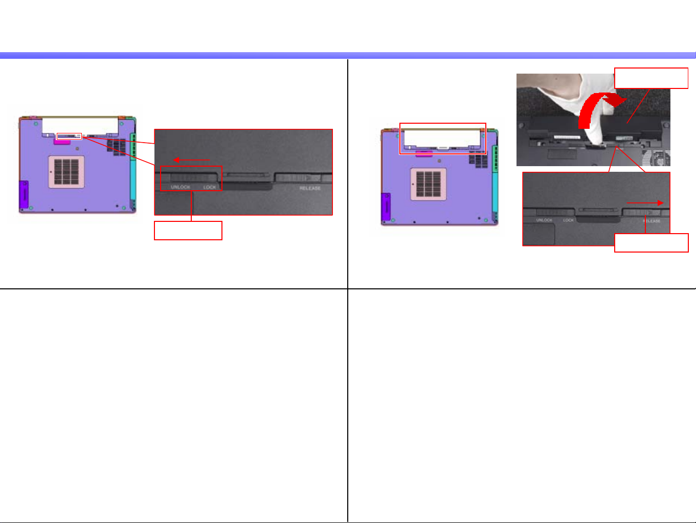
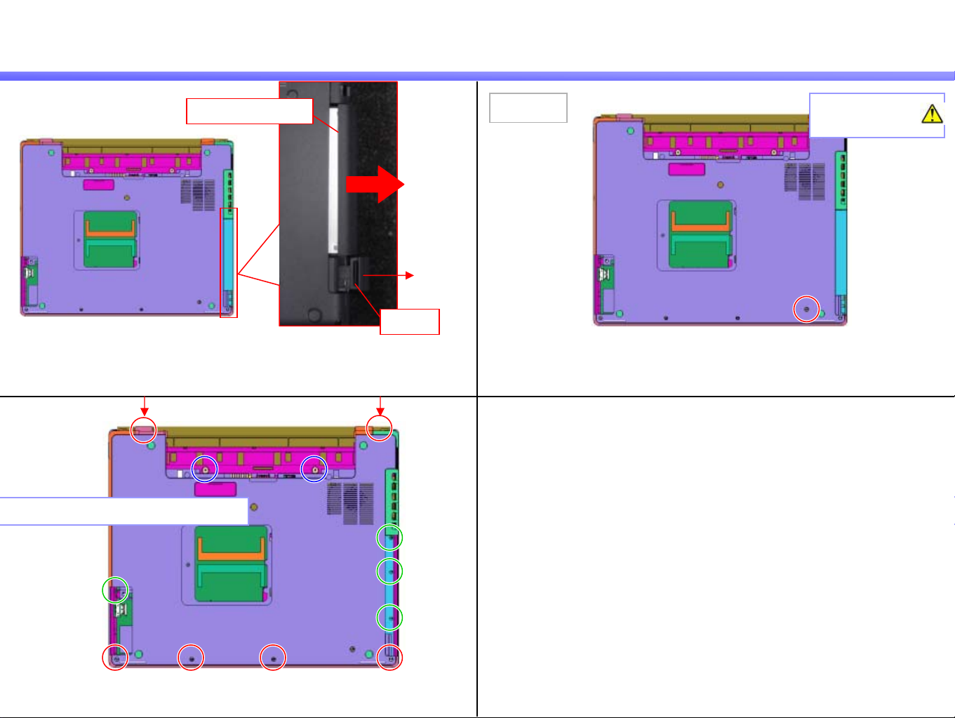
Battery Pack
Confidential
1)
Lock Lever
Slide the Lock Lever to the UNLOCK side.
2)
Slide the Release Lever to the right side,
and turn over the Battery Pack to the rear side then remove it.
Battery Pack
Release Lever
BX Series
1.MS-1-D.3
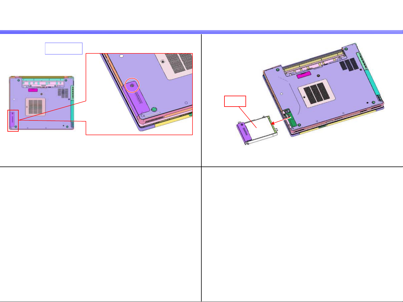
HDD
1) 2)
Screw:B20
Confidential
HDD
Remove the HDD.Remove the screw.
BX Series
1.MS-1-D.4
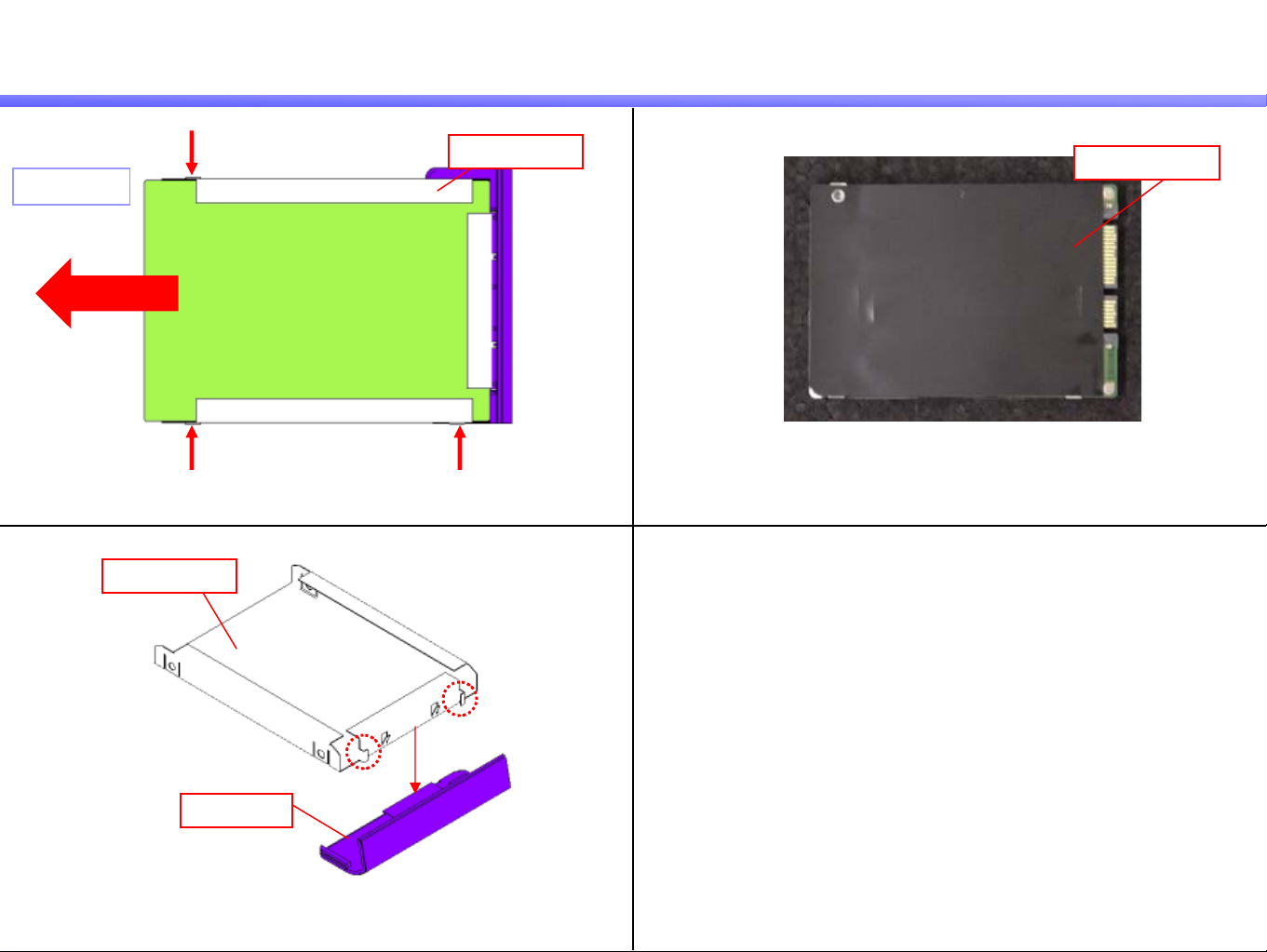
Parts of the HDD
Confidential
1)
Holder (HDD)
Screw:B13
HDD
Remove the three screws, and remove the HDD from the Holder (HDD).
3)
Holder (HDD)
2)
Insulator (HDD)
Peel off the Insulator (HDD).
Door (HDD)
Remove the Door (HDD) while diseng aging the dete nt (two pl ac e s).
BX Series
1.MS-1-D.5
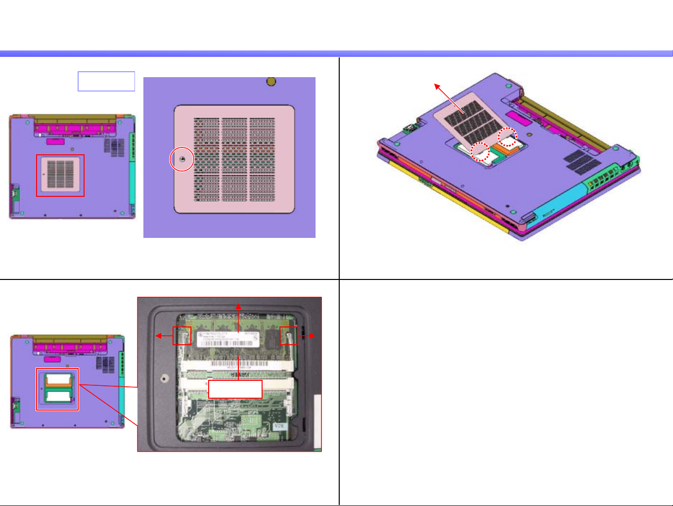
Cover (Memory), Memory
Confidential
1)
3)
Screw:B7
Remove the screw.
1
2)
Remove the Cover (Memory) while disengaging the detent (two places).
2
1
Memory
Outspread the tabs (arrow 1), and pull out the Memory diagonally upward
(arrow 2).
*When two Memory are installed, remove the other side of the Memory in
the way as above.
BX Series
1.MS-1-D.6
Optical Disc Drive, Screws
Confidential
1)
2)
Optical Disc Drive
Push the lever once and pull out it in the direction
of the arrow, then remove the Optical Disc Drive.
Lever
Remark
When there is a screw in the position of figure, remove
the Optical Disk Drive after removing the screw.
Screw:B19
(Special screw)
Screw: Red-B2 / Blue-B11 / Green-B5
Remove the 12 screws.
BX Series
1.MS-1-D.7
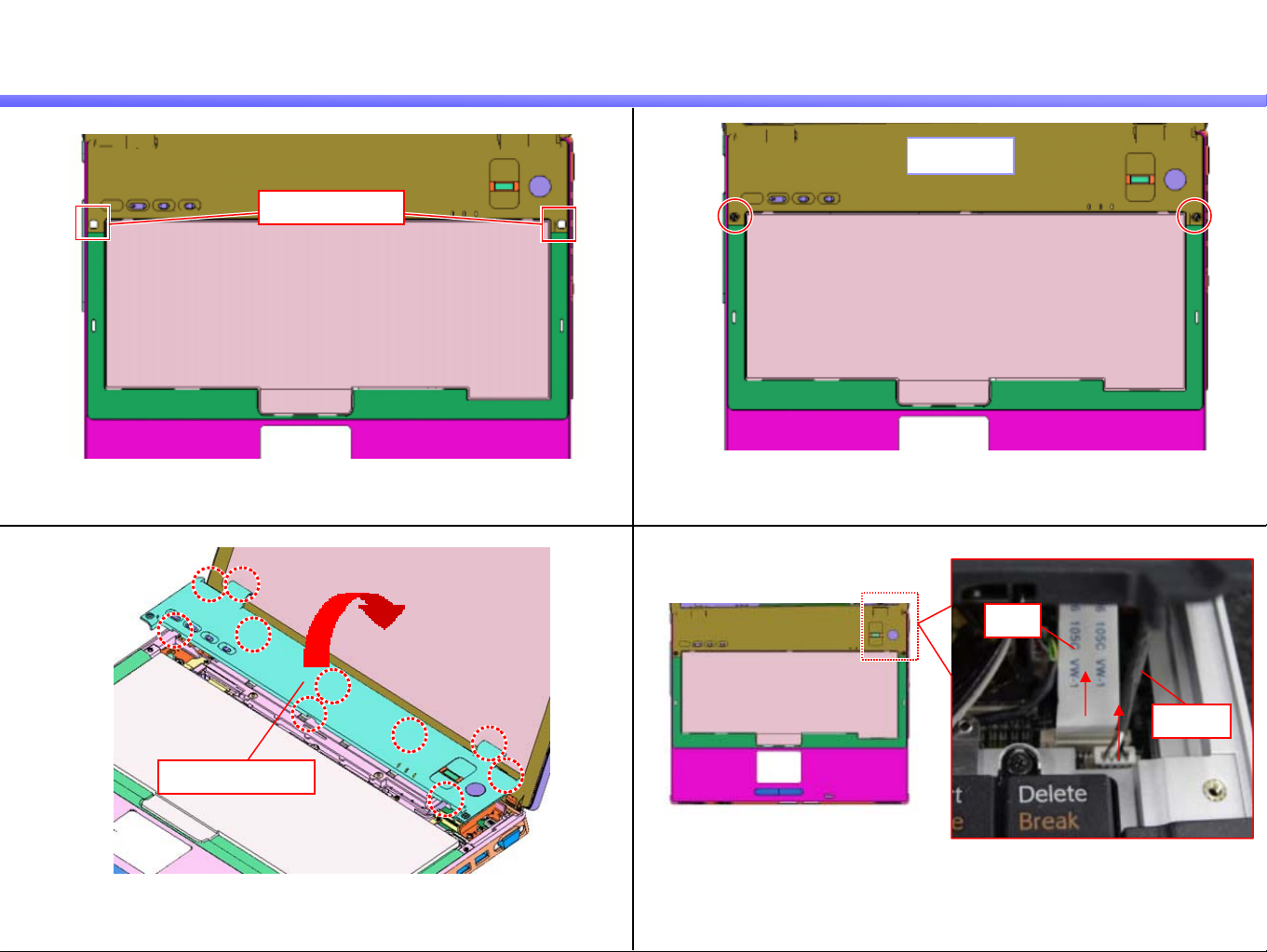
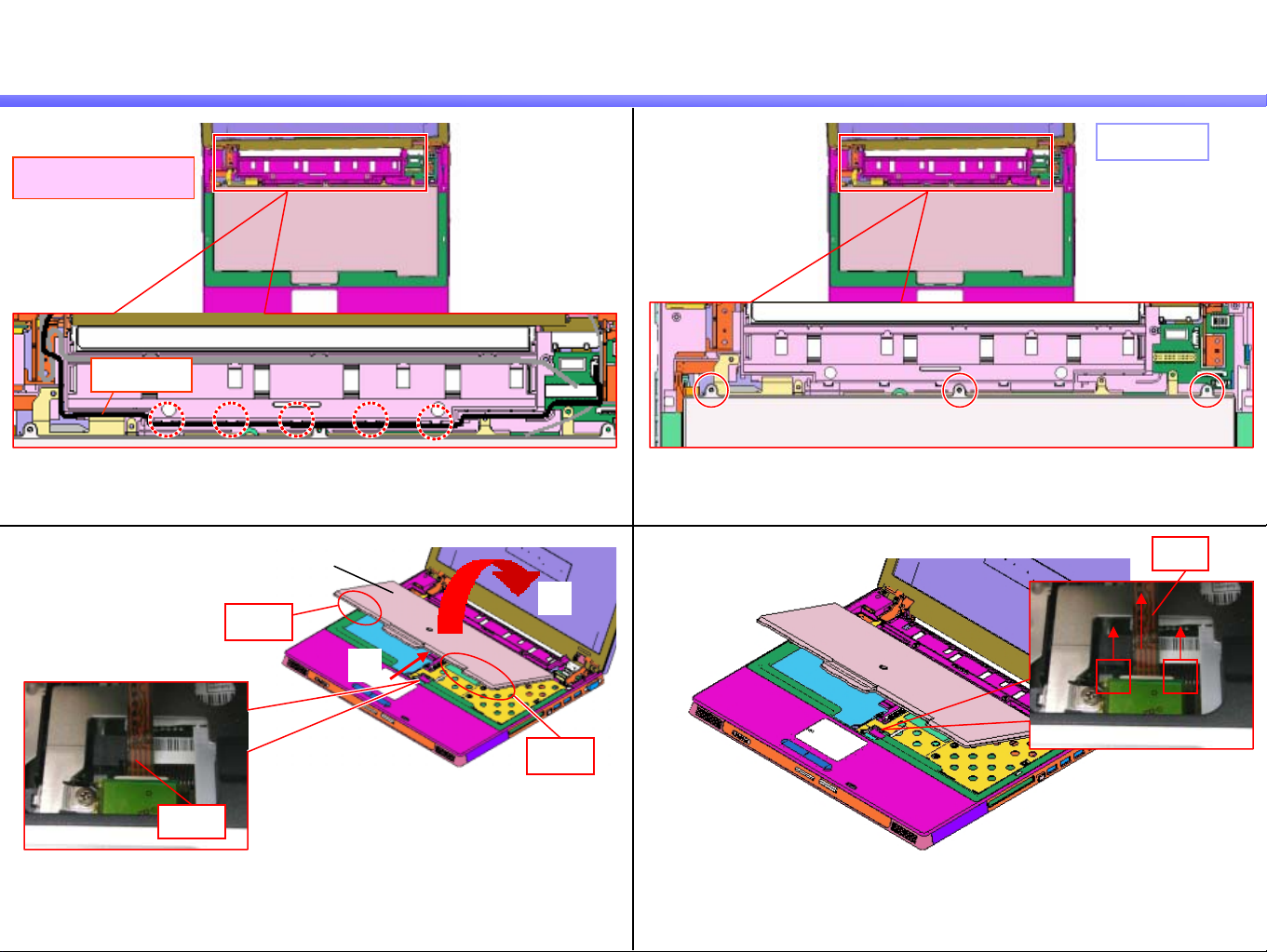
Hood (Keyboard)
1) 2)
Rubber (Screw)
Confidential
Screw:B3
3)
Keyboard
Peel off the Rubber (Screw) (two places). Remove the two screws.
Keyboard
4)
FFC
Hood (Keyboard)
Harness
Turn over the Hood (Keyboard) to the rear side.
* The detents (10 places) are engaged.
Disconnect the FFC and the Harness.
*FFC --- Slide the lock lever upward and release the lock.
Harness --- Pull out it upward.
BX Series
1.MS-1-D.8
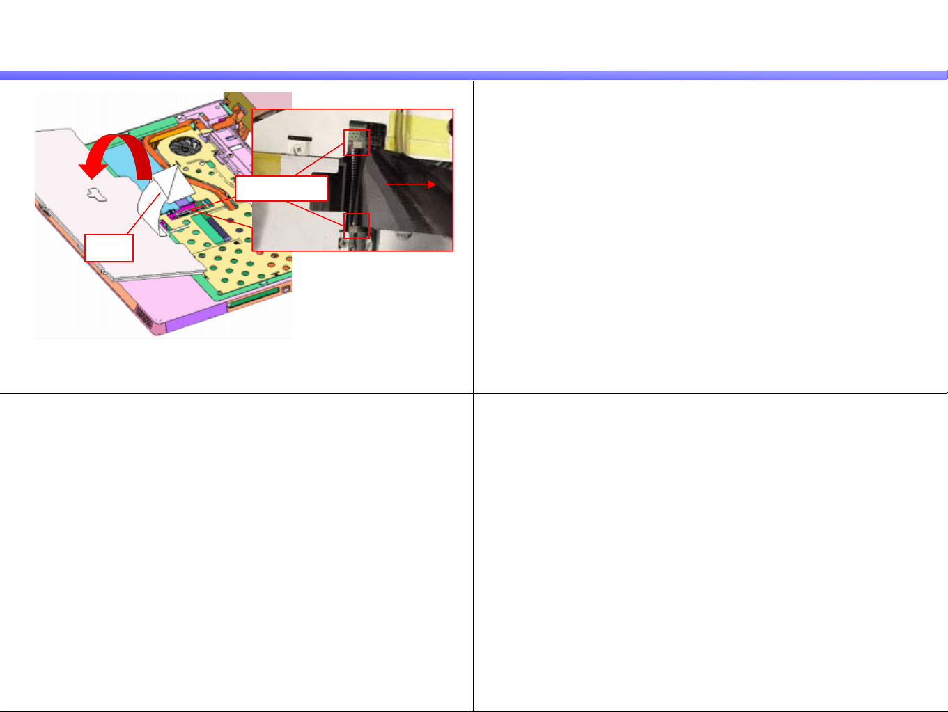
Parts of the Hood (Keyboard) -1
1) 2)
[MA]
Kapton Tape
1st Model
Kapton Tape
4
Confidential
FFC
3)
Screw: B4
Peel off the Kapton Tape.
*1st Model --- Five places
Other --- One place
Disconnect the FFC (two places).
*Slide the lock lever in the direction of the arrow, and release the lock.
4)
Harness
SWX Board
Remove the four screws and the SWX Board. Disconnect the Harness.
BX Series
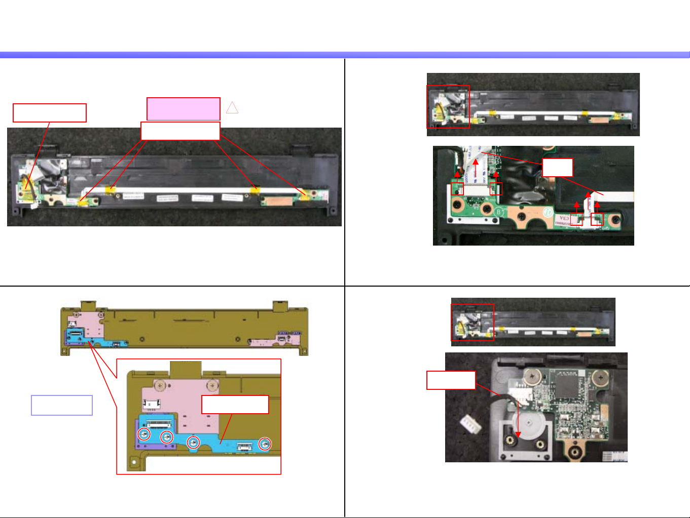
1.MS-1-D.9
Parts of the Hood (Keyboard) -2
5) 6)
Screw: B11
IFX Board
Confidential
FFC
Remark
2nd Model
The FFC is secured with double side tape (two places).
Remove the two screws and the IFX Board.
[MA]
4
Disconnect the FFC.
*Slide the lock lever in the direction of the arrow and release the lock.
7)
Screw: B4
FFCDouble Side Tape
SWX Board
Remove the two screws and the SWX Board.
BX Series
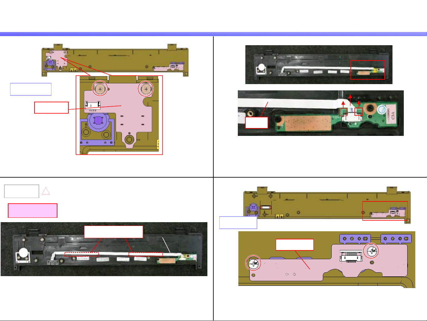
1.MS-1-D.10
Keyboard -1
Confidential
1)
2)
Camera Model
Harness
Release the Harness from the detent (five places). Remove the three screws.
3) 4)
Keyboard
2
Rib
1
Screw: B5
FPC
Rib
FPC
Release the rib (two places) by sliding the Keyboard in the direction of
the arrow 1, and lift it from the front side lightly.
*Notice : The FPC coming from the Keyboard is connected with
Mother Board.
Slide the lock lever in the direction of the arrow
and release the lock, then disconnect the FPC.
BX Series
1.MS-1-D.11
Keyboard -2
5)
FPC
Turn over the Keyboard to the front side, and disconnect the FPC.
*Slide the lock lever upward and release the lock.
Confidential
Lock Lever
BX Series
1.MS-1-D.12
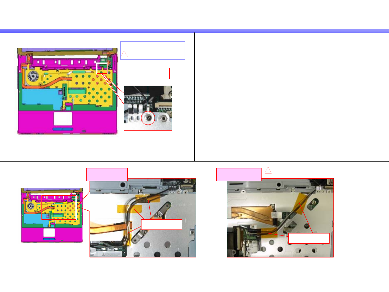
LCD Section -1
1)
Screw: 1st Model - B4
4
Remove the one screw.
* It secures the lug terminal.
[MA]
2nd Model - B3
Lug Terminal
Confidential
2)
1st Model
Kapton Tape
Peel off the Kapton Tape.
*1st Model --- Three places
2nd Model --- Two places
2nd Model
4
[MA]
Kapton (FPC)
BX Series
1.MS-1-D.13
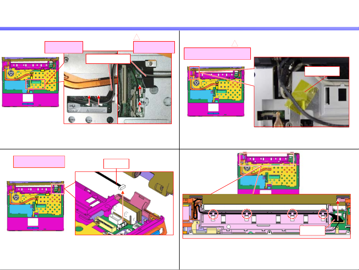
LCD Section -2
Confidential
3)
5)
1st Model 2nd Model
Disconnect the Coaxial Cable (two places).
* Disconnect it vertically.
Camera Model
Camera Model
Coaxial Cable
Harness
4
[MA]
4)
1st (Camera) Model
6)
[MA]
4
Peel off the Kapton Tape.
Kapton Tape
Disconnect the Harness upward.
Harness
Disconnect the Harness upward and release it from
the detent (four places).
BX Series
 Loading...