

Page 1

Welcome
Thank you for purchasing a Sony VAIO® computer! Your new computer is a superb blend of high technology and easy-to-use
functionality. The information provided here is designed to help you to become familiar with the hardware and software
programs included with your computer.
View the Electronic Flyer, which provides updates and supplemental information about your computer.
Go to the Sony online support Web site, to view the VAIO® Computer Specifications, which lists your computer's
hardware specifications and preinstalled software information.
For information about the Sony software preinstalled on your computer, click Start in the Windows® taskbar, and
then click Welcome to VAIO life.
Page 1
Page 2

Getting Started
Congratulations on your purchase of the Sony VAIO® computer! Your new, high-performance, multimedia computer combines
state-of-the-art computer functionality with the latest audio, video and information technology features.
Unpacking Your Computer
Planning an Ergonomic Work Space
Page 2
Page 3

Unpacking Your Computer
Your computer may not be supplied with all of the accessories shown, depending on the computer configuration purchased.
For details on the accessories supplied with your computer, see the online Specifications sheet.
Your VAIO® computer is not supplied with System or Application Recovery CDs. Use the VAIO Recovery Wizard utility to
recover your computer's operating system and preinstalled software.
Computer and supplied accessories
*T his ac c es sory is only available with c ertain c omputer models .
Manuals
VAIO® Computer Quick Start — Provides basic information on setting up and registering your computer. The Quick
Start also provides resources for technical support, safety guidelines and owner information.
About RAID Systems — Contains an overview of RAID-0 and RAID-1 levels, along with basic information about RAID
configuration. This guide is available only with configure-to-order (CTO) computers that are shipped as RAID-0 or
RAID-ready.
Online Documentation
VAIO® Computer User Guide — Contains features and specifications of your computer. It also includes information
on the Microsoft® Windows® XP Media Center Edition operating system, the software programs included with your
computer, and solving common problems.
To access the online User Guide:
1.
Click Start in the Windows taskbar, then click Help and Support.
2.
From the VAIO Help and Support Center menu, click VAIO User Guide.
Specifications — The online specifications sheet describes the hardware and software configuration of your VAIO
computer.
To view the online specifications sheet:
1.
Connect to the Internet.
Page 3
Page 4

2.
Go to the Sony online support Web site at http://www.sony.com/pcsupport.
3.
Click the Documentation button and follow the on-screen instructions to locate your model's
specifications sheet.
VAIO Software — Provides specific information on certain preinstalled software on your computer.
To access this online software information:
1.
Click Start in the Windows® taskbar.
2.
Click Welcome to VAIO life.
Hard Disk Drive Recovery
Your computer is equipped with the VAIO Recovery Wizard utility program that recovers your computer's operating system
and preinstalled software.
For online information about hard disk drive recovery:
1.
Click Start in the Windows® taskbar, then click Help and Support.
2.
From the VAIO Help And Support Center, click VAIO Recovery Options.
You can create a VAIO Recovery Media Kit using CD-R, single layer DVD+R, or single layer DVD-R media on VAIO
computers equipped with the appropriate optical drive (a CD-RW, DVD-RW, or DVD±RW drive).
DVD+RW, DVD-RW, double layer DVD+R, and double layer DVD-R media (when it becomes available) cannot be used to
create a VAIO Recovery Media Kit.
Other
A software library, containing the Microsoft® software and Sony® end-user license agreements.
Page 4
Page 5

Planning an Ergonomic Work Space
Before you set up your new computer, find the best location for your new computer and plan your work space. There are
several ergonomic factors to consider when you arrange your work space:
Stable work surface — Use a stable work surface large enough to support the computer and other peripheral
equipment.
Ventilation — Leave at least eight inches of space on the left and back sides of your computer to enable proper
ventilation.
Placement of the keyboard, mouse, and other input devices — Place your keyboard, mouse, and other input
devices so that your arms and hands are in a relaxed, comfortable position. The keyboard should be directly in front
of you. Adjust the level of the keyboard so that your lower arms are parallel to the floor. Keep your wrists in a
relaxed position when you are using the keyboard — not angled up or down. Use the palmrest briefly, for resting.
While typing, never use the palmrest or rest your hands on the table. Position the mouse at the same level as the
keyboard. Hold the mouse with a relaxed hand, and use your whole arm to move it. Take breaks during sessions
with your computer. Excessive use of the mouse or a joystick may strain muscles or tendons.
Furniture and posture — Sit in a chair with good back support and armrests. Adjust the level of the chair so your
feet are flat on the floor. A footrest may make you more comfortable. Sit with relaxed, upright posture — avoid
slouching forward or leaning far backward.
Viewing angle of the display — Position the display 18 to 26 inches directly in front of you, with the top of the
screen at or a little below eye level. Use the display's tilting feature to find the best position. You can reduce eye
strain and muscle fatigue by placing the display in the proper position.
Lighting — Choose a location where windows and lights do not create glare and reflection on the display. Use
indirect lighting to avoid bright spots on the display. You can also purchase accessories for your display that help
reduce glare. Proper lighting adds to your comfort and work effectiveness.
Page 5
Page 6

Locating Controls And Ports
This section is intended to familiarize you with the controls, ports and jacks on your computer and supplied accessories.
Your computer may not be equipped with all of these hardware features or accessories. The location of the controls, ports,
and jacks may vary from the illustrations shown in this section. To view the specific connection capabilities for your
computer, see the online Specifications sheet.
About the Front Panel
About the Back Panel
About the Sub-woofer
About the Keyboard
About the Remote Control
About the i.LINK Port
Page 6
Page 7

About the Front Panel
The front panel of your VAIO® Computer enables access to drives, memory card readers, ports and jacks that enable you to
connect compatible peripheral devices.
Page 7
Page 8
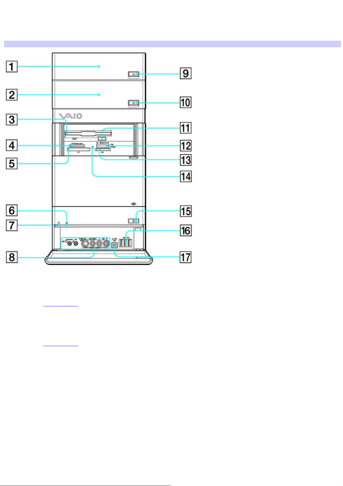
Front panel
Your computer may not be equipped with all of these hardware features or accessories. The location of the controls, ports,
and jacks may vary from the illustrations shown in this section.
Front panel
1 Optical drive 1
See the online Specifications sheet for optical drive information.
2 Optical drive 2
See the online Specifications sheet for optical drive information.
3 Floppy disk drive
Reads and writes data from and to a 3.5-inch floppy disk.
4 xD-Picture Card memory card reader
Reads and writes data from and to xD-Picture Card media.
5 CompactFlash® and Microdrive memory card reader
Reads and writes data from and to CompactFlash and Microdrive media.
Page 8
Page 9

6 Optical drive access indicator
Light is amber while reading and writing data from and to the optical drives.
7 Hard disk drive access indicator
Light is amber while reading and writing data from and to the hard disk.
8 Headphones/Line In jack |
Connection for the supplied speakers, optional headphones, or audio device.
Microphone jack
Connection for a microphone (optional).
S-video In jack
Connection for an S-video cable (optional).
Composite video In jack
Connection for a video cable (optional).
Composite audio L In jack
Connection for an audio cable (optional).
Composite audio R In jack
Connection for an audio cable (optional).
9 Optical drive 1 eject button
Ejects a disc from Optical drive 1.
10 Optical drive 2 eject button
Ejects a disc from Optical drive 2.
11 Floppy disk eject button
Ejects a floppy disk from the floppy disk drive.
12 Memory Stick® memory card reader
Reads and writes data from and to Memory Stick®, Memory Stick Pro , and Memory Stick Duo media.
Page 9
Page 10

13 Secure Digital (SD)/MultiMediaCard (MMC) slot
Reads and writes data from and to a Secure Digital (SD) or MultiMediaCard (MMC).
14 Media access indicator1
Light is amber when reading or writing data
15 Power button and power indicator
Press the button to turn the computer on and off. The power indicator light is green when the computer is on and is amber
when the computer is in Stand by mode. The power indicator is off when the computer is turned off.
16 Universal Serial Bus (USB 2.0) ports (3)
Connections for compatible high/full/low-speed USB devices.
17 i.LINK (4-pin) S400 port (IEEE 1394)
Connection for a compatible digital device.
1
T he media ac c es s indic ator lights when reading or writing data with the Sec ure Digital (SD), M emory Stic k®, xD-Picture C ard , or C ompac tFlas h
/M icrodrive s lots .
®
i.LINK is a trademark of Sony used only to designate that a product contains an IEEE 1394 connection. The i.LINK
connection may vary, depending on the software programs, operating system, and compatible i.LINK devices. All products
with an i.LINK connection may not communicate with each other.
Refer to the documentation that came with your compatible i.LINK device for information on operating conditions and
proper connection. Before connecting compatible i.LINK devices to your computer, such as an optical or hard disk drive,
confirm their operating system compatibility and required operating conditions.
To open and close the optical disc drive doors
Your computer is equipped with one or more optical disc drives that have a drive eject button located on the drive door.
After pressing the eject button, wait for the drive to stop reading the CD. It may take a few moments for the drive
tray to eject.
Gently push the drive tray in, when closing the optical drive door. Do not force the door or handle roughly.
After closing the drive door, wait a few moments for the drive to begin reading the CD.
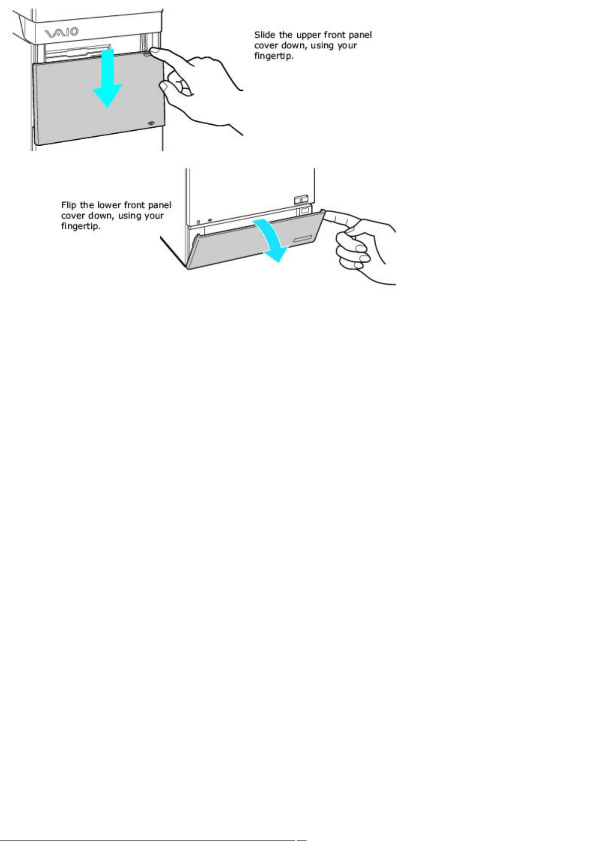
To open the upper and lower front panel covers
The front of your computer is equipped with panels that cover drives, media card slots, jacks and ports. Do not force the
panel covers or handle roughly.
Opening the front panel covers
Page 10
Page 11
Page 11
Page 12

About the Back Panel
The back panel of your computer contains the ports for supplied and optional accessories. The icons on the back panel
locate and identify the ports on your computer.
Page 12
Page 13
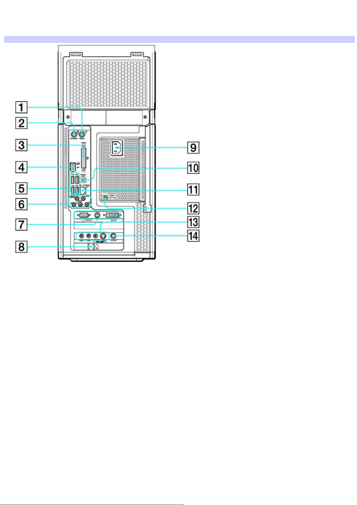
Back panel
The location of certain ports and jacks may vary from the illustration, based on the computer model purchased.
Back panel
1 Mouse port
Connection for a PS/2® mouse.
2 Keyboard port
Connection for a PS/2 keyboard.
3 Printer port
Connection for a parallel device, such as a printer or scanner.
4 i.LINK 6-pin S400 port (IEEE 1394)
Connection and power for a compatible digital device, such as a Sony Digital Handycam® camcorder.
5 Universal Serial Bus (USB 2.0) ports (4)
Connections for compatible high/full/low-speed USB devices.
Page 13
Page 14

6 Microphone jack
Connection for a microphone (optional).
Front/Headphones jack
Connection for the supplied speakers (2-channel), front speakers (5.1 speaker system1), or optional headphones.
Line In jack
Connection for an audio device.
Woofer/Center jack2
Connection for a Sub-woofer3, control module, or center speaker (5.1 speaker system1)
Rear jack
Connection for rear speakers (5.1 speaker system1)
7 Monitor port4
Connection for standard (VGA) monitor.
TV Out (S-video/video) jack
Connection for an S-video cable.
DVI-D monitor port
Connection for a DVI monitor.
8 Modem line jack5
Connection for an RJ-11 telephone cable (optional).
9 AC Input port
Connection for the supplied power cord.
10 S/PDIF Optical Out port
Connection for a digital audio or optical device.
11 Ethernet port
Page 14
Page 15

Connection for a 10BASE-T/100BASE-TX/1000BASE-T Ethernet.
(The port marked with (Network) is for LAN connections only.)
12 Speaker DC Out jack
Connection for the speaker power cable (supplied 2-channel speakers).
13 Composite audio R In jack
Connection for an audio cable (optional).
Composite audio L In jack
Connection for an audio cable (optional).
Composite video In jack
Connection for a video cable (optional).
S-video In jack
Connection for an S-video cable (optional)
14 VHF/UHF port
Connection for a TV coaxial cable (supplied).
1
C ertain V A I O® c omputers that are c onfigured to order (C T O ), may s upply 5 .1 s peakers as part of the ac c essory pac kage. See your c omputer's
specific ations s heet for details on s upplied ac c es sories.
2
Speaker system c onnec tions vary by model and manufac turer. See the information s upplied with your s peaker s ystem for setup details.
3
A s ub-woofer is available with c ertain V A IO c omputer models . See your c omputer's s pec ific ation s heet for details about s upplied ac c ess ories .
4
C ertain V A I O® c omputers that are c onfigured to order (C T O ), may have a DV I -D monitor port ins talled in this loc ation. See your c omputer's s pecific ations
sheet for hardware c onfiguration details
5
A n optional "1-to-2" jack adapter device (s plitter) is required to connect both a telephone and modem line to your computer.
Page 15
Page 16

About the Sub-woofer
Certain VAIO® computers are supplied with a sub-woofer unit to enhance your computer's sound capability. See your
computer's online specifications sheet for information about supplied accessories. Go to the Sony online support Web site
at http://www.sony.com/pcsupport.
Page 16
Page 17

Sub-woofer unit
The sub-woofer is compatible with the speakers supplied with your VAIO computer. See the section, Connecting the
Speakers, for connecting instructions.
Sub-woofer unit
1 Port
The port extends the low frequency response to extend the volume output of the sub-woofer unit.
2 Power knob/volume control
Rotate the knob clockwise to turn on the sub-woofer unit. Control the volume by rotating the knob until the desired volume
is reached. Rotate the knob counter-clockwise to turn off the sub-woofer unit.
3 Power indicator
Light is green while the power is on.
4 Speaker jack
Connection for the speaker cable.
5 Sub-woofer unit cable
Connects the sub-woofer unit to the computer's Headphones jack.
6 AC power cord
Connects the sub-woofer unit to a grounded AC wall outlet or power strip.
Page 17
Page 18

About the Keyboard
This section describes the special and standard functions available for your keyboard.
Page 18
Page 19
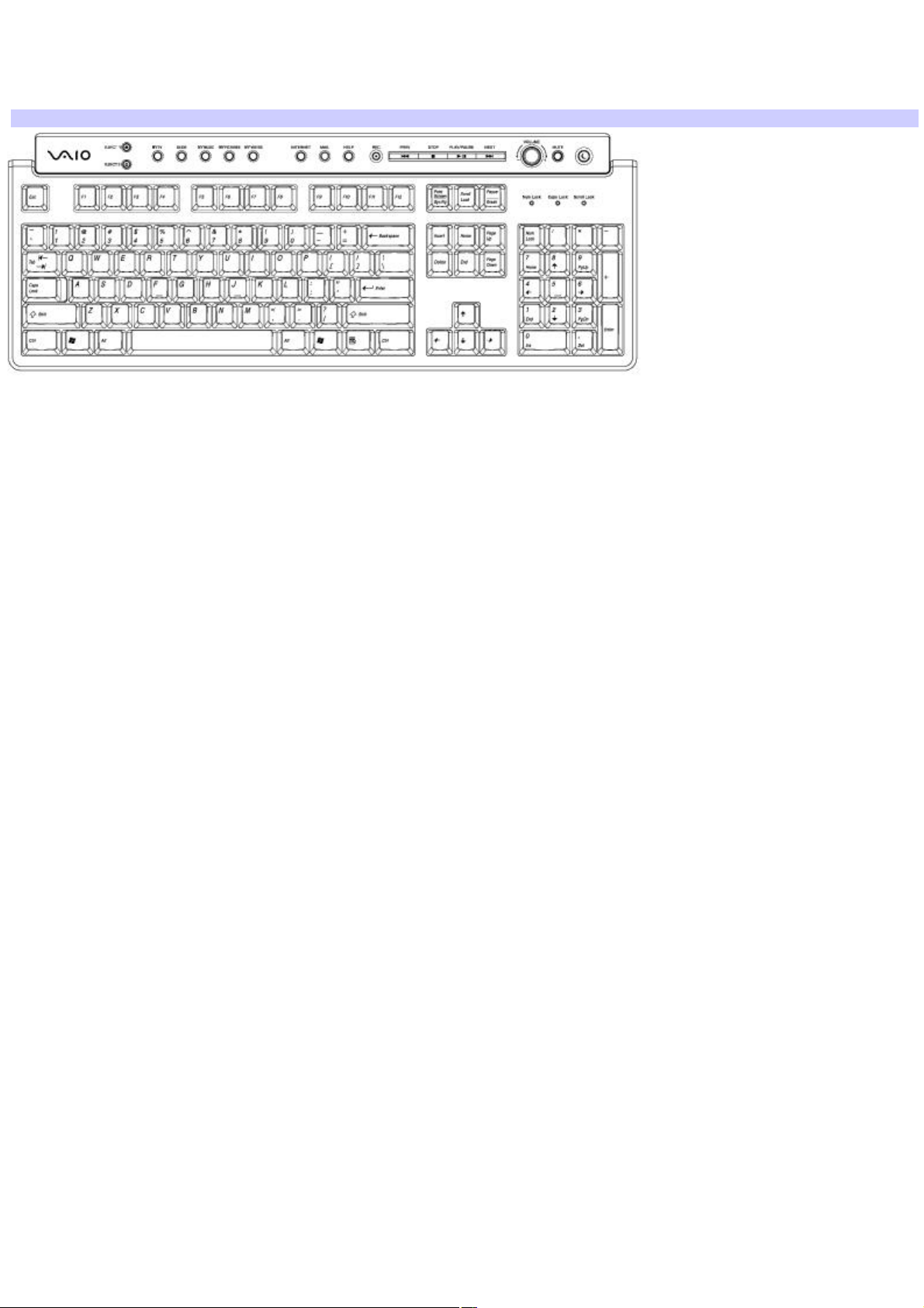
VAIO keyboard with Media Center features
The VAIO® keyboard supplied with your computer has a standard key arrangement with additional keys and controls that
support Microsoft® Windows® XP Media Center Edition features.
VAIO keyboard
BUTTON DESCRIPTION
EJECT 1 Opens and closes the optical drive 1 tray.
EJECT 2 Opens and closes the optical drive 2 tray.
MY TV Opens the My TV window of Windows® Media Center.
GUIDE Opens the TV program guide of Media Center.
MY MUSIC Opens the My Music window of Media Center.
MY PICTURES Opens the My Pictures window of Media Center.
MY VIDEOS Opens the My Videos window of Media Center.
INTERNET Starts the assigned Internet browser.
MAIL Starts the e-mail software program.
HELP Starts the Media Center Help, if Media Center software is running. (If Media Center software is not running,
the Help and Support Center is started.)
REC Records TV programs.
PREV Press once to return to the beginning of the DVD chapter, video track, or audio track.
Press twice to return to the previous DVD chapter, video track, or audio track.
STOP Stops media recording or playback.
PLAY/PAUSE Pauses the movie, video, slide show, or audio track. Press again to resume playback.
Page 19
Page 20

NEXT Advances to the next DVD chapter, video track, or audio track.
VOLUME knob Increases (+) and decreases (-) the volume as you turn the knob.
MUTE Turns the sound off. Press again to restore sound.
STANDBY Places the computer in Stand by mode to reduce power consumption. Press any key briefly to resume normal
operation.
KEY DESCRIPTION
Function The 12 function keys along the top of the keyboard are used to perform certain tasks. The task associated
with each function key may vary between software programs.
Numeric keypad Use the numeric keypad area to type numbers or to perform basic math calculations. Press the Num
Lock key to activate the numeric keypad. (The Num Lock indicator lights.) Press the Num Lock key again to deactivate the
numeric keypad.
Directional Arrows The up, down, left, and right arrow keys move the pointer on the screen.
Applications
The Applications key displays a shortcut menu in certain software programs. Pressing this key is equivalent to
clicking the right mouse button.
Windows
The key with the Microsoft® Windows® logo, displays the Start menu. Pressing this key is equivalent to clicking Start
on the taskbar.
INDICATORS FUNCTION
Num Lock The Num Lock indicator lights when the numeric keypad is activated. When the indicator is off, the directional
arrow and correction keys on the numeric keypad area are active.
Caps Lock The Caps Lock indicator lights to advise you that the keyboard is set to type letters in uppercase. When the
indicator is off, the letters appear in lower case as you type.
Scroll Lock The Scroll Lock indicator lights to advise you that your screen's scrolling pattern has changed. When the
indicator is off, the screen scrolls normally. This function is not available with all software programs.
Page 20
Page 21

About the Remote Control
The Media Center remote control is supplied with VAIO Digital Studio® computers that are equipped with the Microsoft
Windows® XP Media Center Edition operating system.
®
Page 21
Page 22
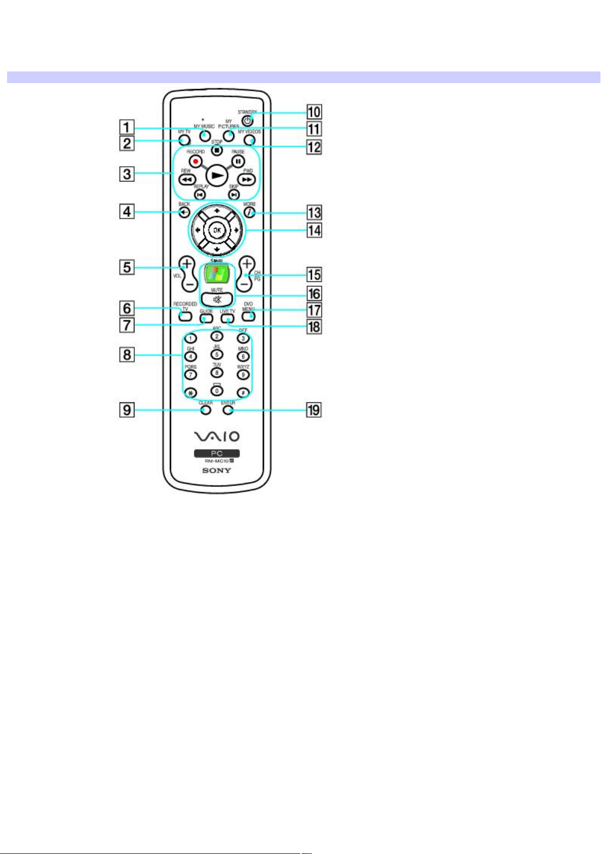
Remote control
The remote control can start and stop video recording and playback, select channels, and set viewing preferences. This
section describes the basic functions of your remote control.
Remote Control
1 MY MUSIC button
Press to view and listen to your music playlists.
2 MY TV button
Press to view the My TV menu.
3
STOP button
Press to stop media playback or TV recording session.
PAUSE button
Press to pause media playback. Press again to resume playback.
FWD button
Page 22
Page 23

Press to fast-forward media at three speeds.
SKIP button
Press to move media forward, for example, one audio track, one DVD chapter, and 30 seconds of recorded TV or video.
REPLAY button
Press to move media backward, for example, one audio track, one DVD chapter, and seven seconds of TV or video.
REW button
Press to move media backward at two speeds.
RECORD button
Press to begin recording.
PLAY button
Press to begin media playback.
4 BACK button
Press to return to the previous window.
5 VOL button
Press to increase (+) or decrease (-) the volume.
6 RECORDED TV button
Press to view previously recorded TV programs (In My TV window)
7 GUIDE button
Press to view the TV program guide for your area.
8 Channel number buttons (0-9)
Press to select specific channels or enter text.
(Press Enter or OK to activate the channel selection.)
9 CLEAR button
Use to backspace and delete entered text.
Page 23
Page 24

10 STANDBY button
Press to place the computer in Stand by mode to reduce power consumption.
11 MY PICTURES button
Press to view pictures or a slide show.
12 MY VIDEOS button
Press to view videos from your video collection.
13 MORE button
Press to view additional options that are available for Media Center features.
14 Directional arrow buttons
Press the Up, Down, Left, and Right arrow buttons to move the pointer on the screen.
OK button
Press OK to select the desired action or window option. If watching full-screen TV press OK to return to the previous
channel. Press OK again to switch between channels.
15 CH/PG (Channel/Page) button
Press to change or page up/down channels (no number input required).
16 START button
Press to open the Media Center Start menu.
MUTE button
Press to turn off the sound. Press again to restore the sound.
17 DVD MENU button
Press to open the main menu on a DVD.
18 LIVE TV button
Press to view TV programming.
19 ENTER button
Page 24
Page 25

Press to activate feature or action, such as channel selection or return to previous channel. (This button's actions are
similar to using the OK button.)
Page 25
Page 26
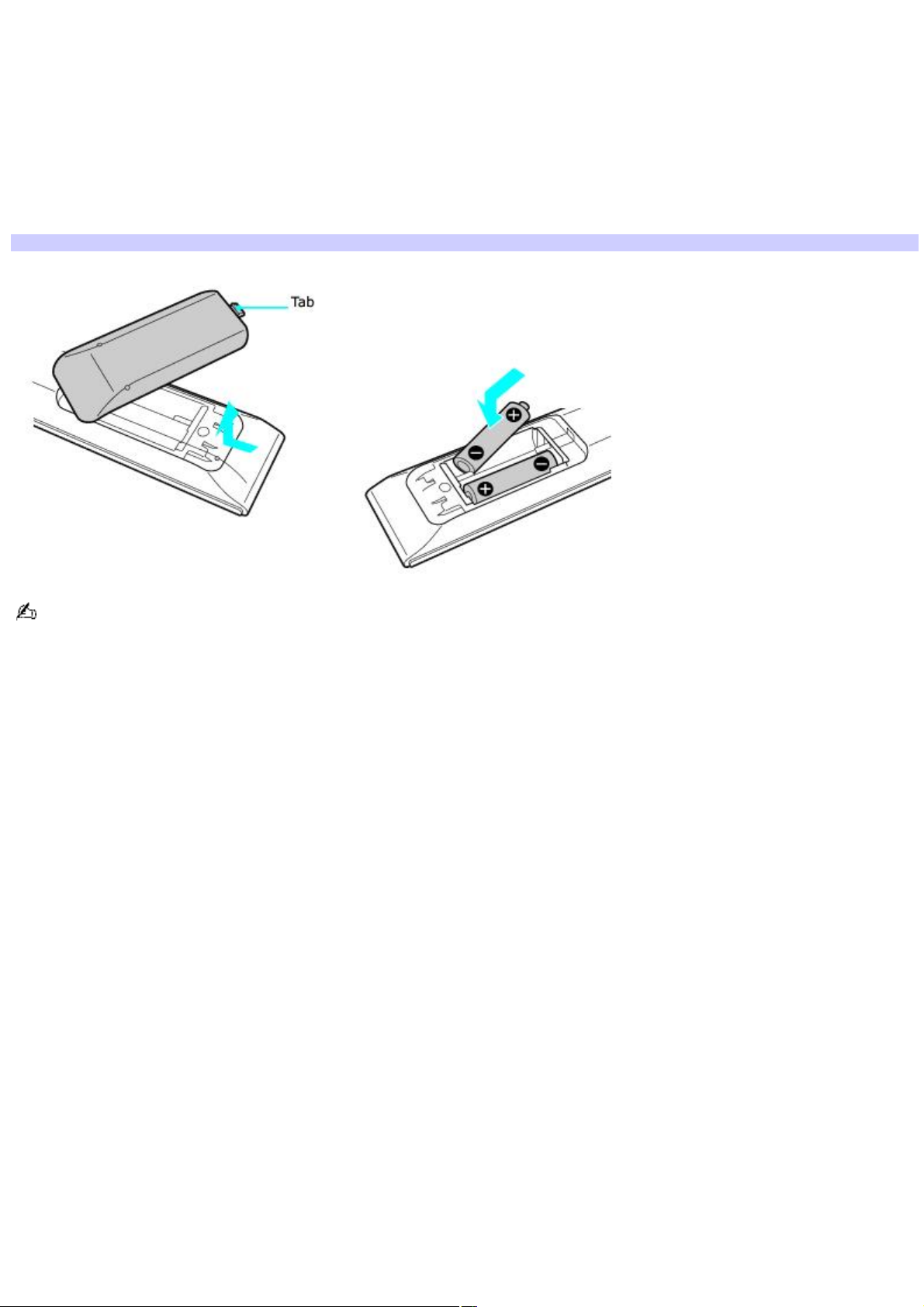
Setting up the remote control
1.
Turn the remote control over.
2.
Press in the tab and lift the battery cover up.
3.
Insert two AA batteries (supplied) into the remote control as shown.
4.
Align the battery cover to the remote control.
5.
Press down until the cover clicks into place.
Inserting batteries into the remote control
If your remote control does not operate properly, you may need to replace the batteries. When your remote control is
not being used for extended periods of time, remove the batteries to avoid possible damage from battery leakage.
Page 26
Page 27

About the i.LINK Port
Your VAIO® computer is equipped with a 4-pin and a 6-pin i.LINK® port. A 4-pin i.LINK port cannot supply power to a
connected i.LINK device. A 6-pin i.LINK port can supply power (10V to 12V) to a connected i.LINK device, if the device is
equipped with a 6-pin connector.
The total power supplied by the 6-pin i.LINK port does not exceed 6 watts.
Page 27
Page 28

Connecting an i.LINK (IEEE 1394) device
1.
Use the symbol to locate the i.LINK port on your compatible i.LINK device and on your computer. Plug the i.LINK
cable connector into this port.
2.
Plug the other end of the cable into the corresponding 4- or 6-pin i.LINK port on your computer.
See the instructions supplied with your i.LINK device for more information on installation and use.
Page 28
Page 29

Setting Up Your Computer
Your computer may not be equipped with all of the hardware features described in the section. The location of the controls,
ports, and jacks may vary from the illustrations shown. See the online Specifications sheet for your computer's specific
hardware configuration.
Connecting a Display (Monitor)
Connecting the Speakers
Connecting 5.1 (6-Channel) Speaker Systems
Configuring Software for Your Speaker System
Connecting the Keyboard and Mouse
Connecting the Telephone and Modem
Connecting the Power Cords
Turning On Your Computer
Page 29
Page 30
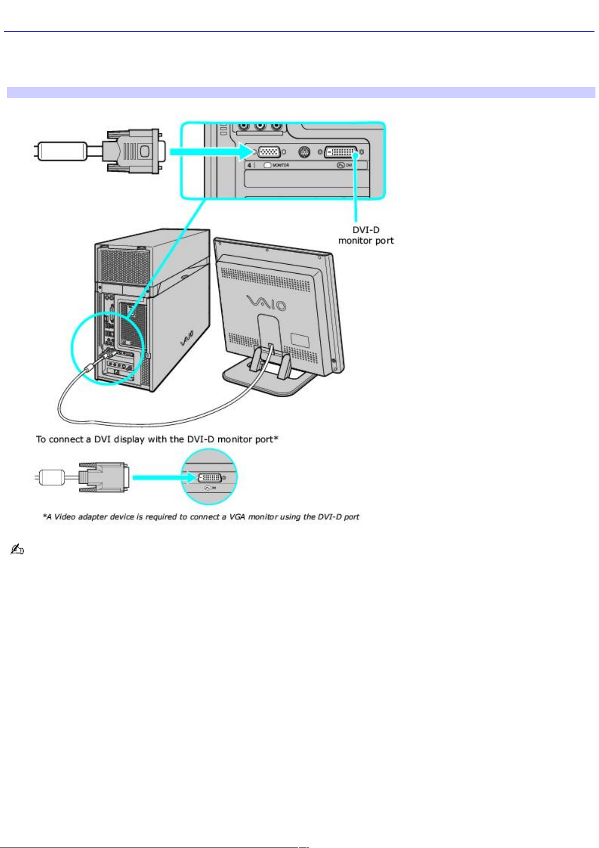
Connecting a Display (Monitor)
1.
Plug the display's cable into the appropriate monitor port.
2.
If necessary, plug the display's cable into the rear of the display.
To connect a display
Install your equipment so that you can easily reach the power outlet in the event of an emergency.
Page 30
Page 31
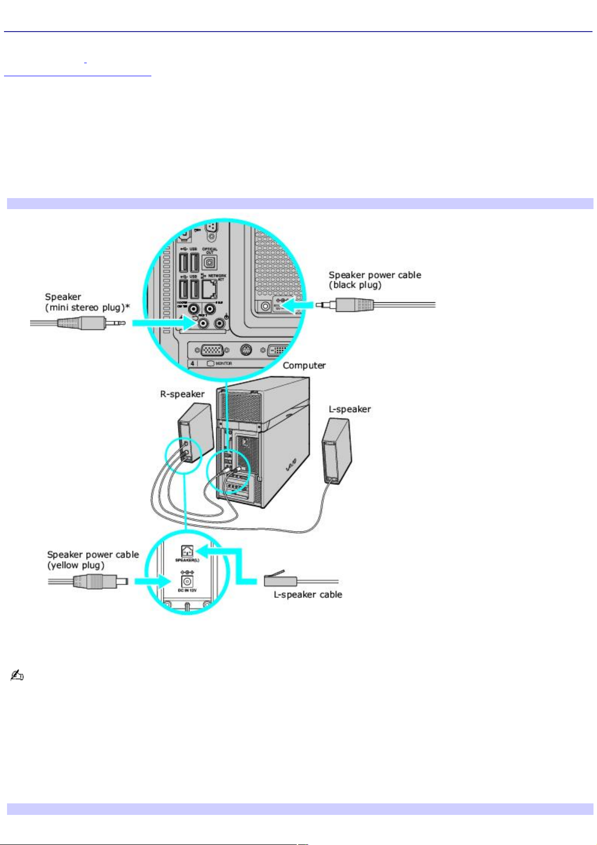
Connecting the Speakers
Your VAIO® computer is supplied with 2-channel speakers. Certain models are supplied with a sub-woofer unit or 5.1
speaker systems1. For information about supplied accessories, go to the Sony online support Web site at
http://www.sony.com/pcsupport to view your computer's specifications sheet.
To connect the 2-channel speakers (supplied)
1.
Plug the cable attached to the back of the left speaker into the Speaker(L) jack on the back of the right speaker.
2.
Insert the yellow plug of the speaker power cable into the DC In jack on the back of the right speaker.
3.
Insert the black plug of the speaker power cable into the DC Out jack located on the back panel of your
computer.
To connect the computer and speakers
4.
Insert the mini stereo plug of the cable that is attached to the right speaker, into the Front/Headphones jack,
located on the back panel of your computer.
You can also plug the right speaker's mini stereo plug into the headphones jack located on the lower front panel of
your computer.
To connect a sub-woofer unit
Certain VAIO® computer models are supplied with a sub-woofer unit which requires a slightly different setup. See your
computer's specifications sheet for information about supplied accessories.
1.
Insert the mini stereo plug of the cable that is attached to the right speaker into the speaker jack, located on
the left side of the sub-woofer unit.
To connect the speakers and sub-woofer unit
Page 31
Page 32
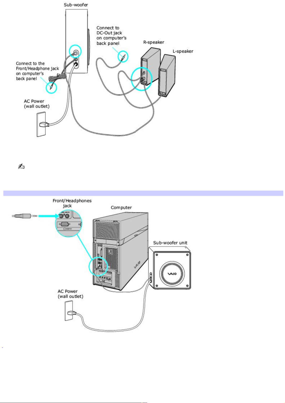
2.
Insert the mini stereo plug from the sub-woofer unit's cable into the Headphones jack, located on the back panel
of your computer.
You can also plug the sub-woofer's mini stereo plug into the headphones jack located on the lower front panel of
your computer.
3.
Plug the sub-woofer unit's power cord into a grounded AC wall outlet or power strip.
To connect the sub-woofer to the com puter
1
C ertain V A I O c omputers that are c onfigured-to-order (C T O ), may be supplied with a 5.1 speaker s ys tem. For details about us ing this type of s peaker
sys tem, s ee the information provided with the s ys tem.
Page 32
Page 33
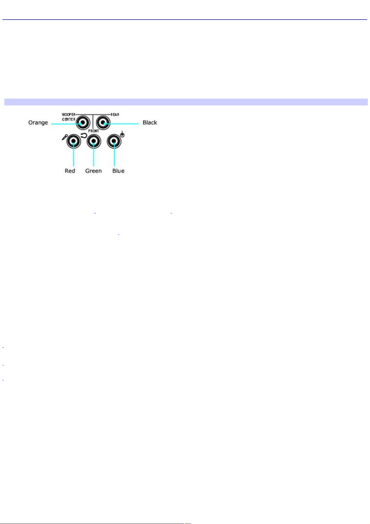
Connecting 5.1 (6-Channel) Speaker Systems
Certain VAIO® computers that are configured-to-order (CTO), are supplied with a 5.1 speaker system, or you may wish to
use your 5.1 (6-channel) speaker system. Speaker configuration can vary, depending on the speaker components used.
To set up the speakers with your computer:
Match the color of the mini stereo plugs (speaker system) to the color of the speaker jacks on the back panel of
your computer.
Review the connection instructions provided with your speaker system, as the connection setup may vary.
Audio jacks (computer back panel detail)
Jack color Description/Connection
Orange Woofer/Center1 — Connect a Sub-woofer2, control module,
or Center speaker (5.1 speaker system3)
Black Rear — Connect rear speakers (5.1 speaker system).
Red Microphone — Connection an optional microphone.
Green Front/Headphones — Connect the supplied speakers (2-channel), front speakers (5.1 speaker system), or
optional headphones.
Blue Line In — Connect an audio device.
1
Speaker system c onnec tions vary by model and manufac turer. See the information s upplied with your s peaker s ystem for setup details.
2
A s ub-woofer is available with c ertain V A IO® c omputer models . See your c omputer's s pec ific ation s heet for details about s upplied ac c essories .
3
C ertain V A I O c omputers that are c onfigured to order (C T O ) may s upply a 5.1 s peaker sys tem as part of the ac c es sory package. See your c omputer's
specific ations s heet for details on s upplied ac c es sories.
Page 33
Page 34

Configuring Software for Your Speaker System
When using 5.1 (digital or analog) speaker systems, certain software programs require setting changes to enable proper
audio performance.
To configure RealTek® Sound Effect Manager software
For 6 channel-analog speakers
1.
Click Start in the Windows® taskbar, and then click Control Panel.
2.
Click Sounds, Speech, and Audio Devices, and then click Sound Effect Manager.
The Sound Effect Manager window appears.
3.
Click Speaker Configuration.
4.
From the drop-down menu on the left, select 6CH Speaker.
5.
Close the Sound Effect Manager window.
For 6 channel-digital speakers
1.
Click Start in the Windows® taskbar, and then click Control Panel.
2.
Click Sounds, Speech, and Audio Devices, and then click Sound Effect Manager.
The Sound Effect Manager window appears.
3.
Click Speaker Configuration.
4.
From the drop-down menu on the left, select Dolby Digital 5.1.
5.
Close the Sound Effect Manager window.
To configure Media Center software
Your computer's factory default settings for audio can be changed using the Media Center Settings feature. You can switch
between 2-channel, 6-channel, or S/PDIF output modes.
1.
Use the Media Center remote control, your keyboard, or mouse, to start the Media Center software program.
2.
Select Settings and press OK.
The Settings window appears.
3.
From the Settings window, select DVD, and then press OK.
The DVD Settings window appears.
4.
Select Audio and press OK.
InterVideo® software's audio settings window appears.
5.
Select Configuration and press OK.
6.
From the section, Set sound output to match your system, use +/- to locate the appropriate speaker system
setup.
To enable S/PDIF output, select SPDIF.
7.
Select Save, and press OK.
8.
Press on the remote control to return to the Media Center Start menu.
Page 34
Page 35

To configure WinDVD software
1.
Click Start in the Windows® taskbar, and point to All Programs.
2.
Point to InterVideo WindDVD 5, and the click on InterVideo WinDVD 5 for VAIO.
The InterVideo WinDVD for VAIO window opens.
3.
Right-click in the WinDVD window.
A shortcut menu appears.
4.
Click Setup..., to view the Setup dialog box.
5.
Select the Audio tab.
6.
From the section, Audio Speaker Configuration, select 6-channel speaker (5.1 Home Theater) or the desired
speaker configuration.
To enable S/PDIF, go to Audio Output Configuration and select Digital (S/PDIF) out to External Processor.
7.
Click Apply, and then click OK.
InterVideo® software automatically detects the type of speaker system. You may notice that some options are
disabled or are not available.
Page 35
Page 36
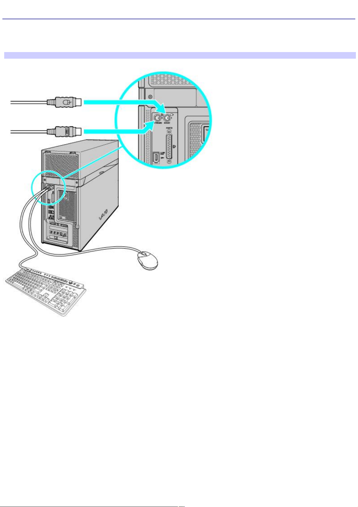
Connecting the Keyboard and Mouse
1.
Plug the keyboard cable into the keyboard port on the back of the computer.
2.
Plug the mouse cable into the mouse port on the back of the computer.
To connect the keyboard and mouse
Page 36
Page 37
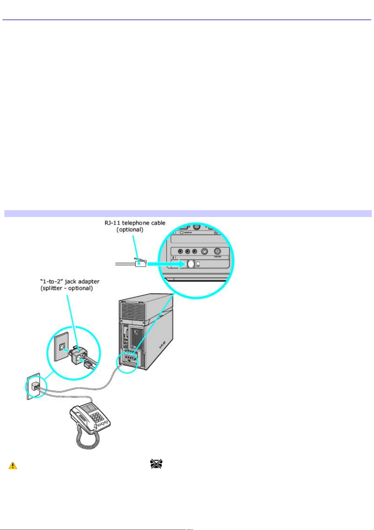
Connecting the Telephone and Modem
Your computer is equipped with a single modem line jack to connect your installed modem with your telephone wall jack. To
use your wall jack for both telephone and modem lines, purchase an additional RJ-11 telephone cable and a "1-to-2" jack
adapter device (splitter).
To connect the modem
1.
Unplug your telephone from the wall jack and set aside.
2.
Plug another telephone cable (optional) into the modem line jack located on the back panel of your computer
3.
Plug the other end of the cable into the wall jack.
To connect the telephone and modem
1.
Unplug your telephone cable from the wall jack.
2.
Insert the telephone's cable into one of the jacks on an optional "1-to-2" jack adapter device (splitter).
3.
Insert one end of a second telephone cable (optional) into the other jack on the splitter device.
4.
Insert the plug end of the splitter device into the wall jack.
5.
Plug the second telephone cable into the modem line jack located on the back panel of the computer.
To connect the telephone and modem
Your computer has a protective sticker covering the Ethernet port located on the rear panel. Connect
10BASE-T, 100BASE-TX, or 1000BASE-T cables to the Ethernet port, depending on your computer's Ethernet port
specification. Using incorrect cables or a telephone cable may result in an electric current overload that can cause a
malfunction, excessive heat, or fire in the Ethernet port. For help on connecting to a network, see your network
administrator.
Page 37
Page 38
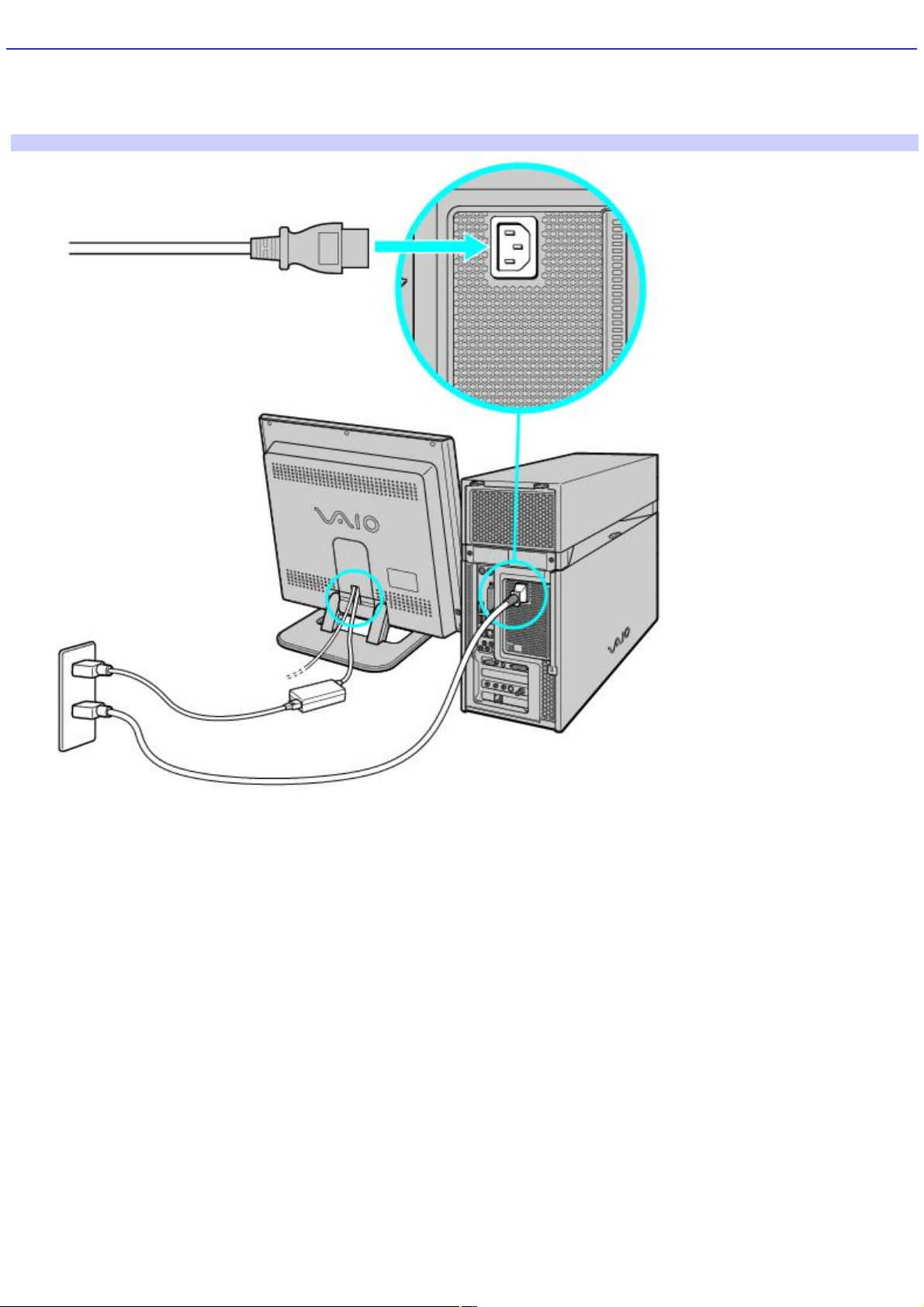
Connecting the Power Cords
1.
Plug the power cord into the back of the computer.
2.
Plug both the display and computer power cords into a grounded AC wall outlet or a power strip.
To connect the power cords
Page 38
Page 39
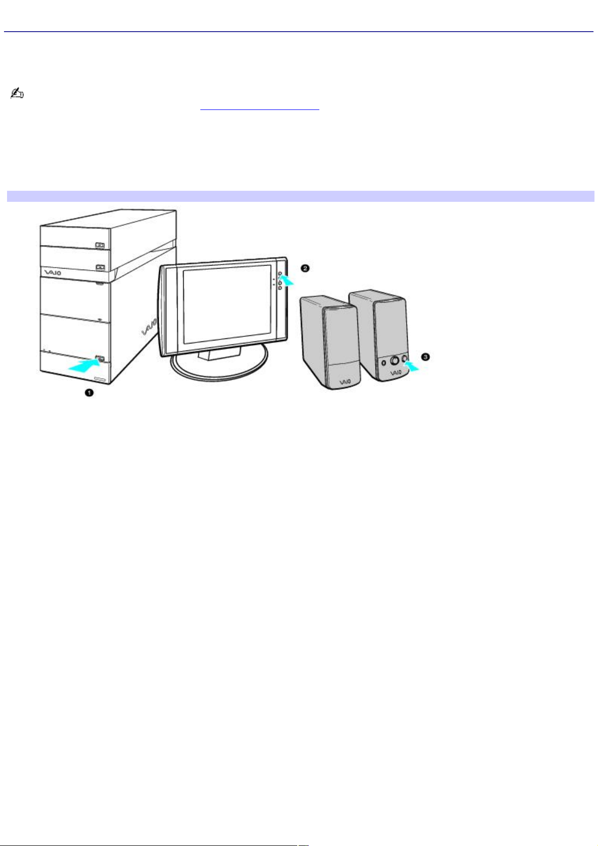
Turning On Your Computer
When you start your computer for the first time, your computer may detect new equipment and display a dialog box that
prompts you to restart your computer. Respond to this prompt immediately.
Before turning on your computer, set up the cables and connections required to use Microsoft® Windows® XP Media
Center Edition features. See the section, Setting Up Media Center.
1.
Press the power button on the computer to turn on the power.
2.
Press the power button on the display to turn on the power.
3.
Press the power button on the right speaker to turn on the power.
To turn on your computer
Page 39
Page 40

Setting Up Media Center
Your VAIO Digital Studio® computer has the Microsoft® Windows® XP Media Center Edition operating system to enhance your
computing experience. Media Center provides you with a wide range of TV, DVD, and video viewing, as well as music
recording and playback. This section describes how to set up your TV, set-top box, and other equipment.
Setting Up TV Connections
Connecting the Remote Sensor and Remote Sensor Control
Connecting Other Devices
Registering Your Computer
Turning Off Your Computer
Page 40
Page 41

Setting Up TV Connections
The best method of connecting your computer, TV monitor or display, and TV programming access, is determined by the
type of cable service connection available in your home. Your computer's hardware configuration may vary from the
illustrations shown in this section. See the online Specifications sheet for details about your computer's hardware
configuration.
Your VAIO Digital Studio ® computer is supplied with certain video cables. Depending on your in-home cable access, you
may require extra cables, adapters or connection equipment that are optional for your computer.
Page 41
Page 42

Connecting to standard cable access (CATV)
Option 1
1.
Connect one end of the TV coaxial cable (supplied) to your cable service access.
2.
Connect the other end of the TV coaxial cable to the VHF/UHF port on the back panel of your computer.
To connect in CATV mode (Option 1)
Option 2
1.
Connect one end of a TV coaxial cable (optional) to your cable service access. Connect the other end to the
single-connection side of a splitter adapter.
2.
Connect the TV coaxial cable (supplied) to the double-connection side of the splitter adapter. Connect the other
end to the VHF/UHF port on the back panel of your computer.
3.
Connect a third TV coaxial cable (optional) to the double-connection side of the splitter adapter. Connect the
other end to the VHF/UHF port on the back of your TV monitor or display.
To connect in CATV mode (Option 2)
Page 42
Page 43

Connecting to a standard antenna (air) system
You can connect your computer to an indoor/outdoor antenna system, using Option 1 or 2 from the previous section,
Connecting to standard cable access (CATV) The antenna system in your home may require a VHF/UHF RF
combiner/transformer (optional) to connect your computer and the indoor/outdoor antenna system.
If you are connecting to an indoor/outdoor antenna system, you may need to reorient the antenna for better
reception.
Option 1
1.
Connect one end of a TV coaxial cable (optional) to your antenna outlet. Connect the other end to a VHF/UHF RF
combiner/transformer (optional).
2.
Connect the TV coaxial cable (supplied) from the combiner/transformer to the VHF/UHF port on the back panel of
your computer.
Option 2
1.
Connect both ends of the antenna's twin lead cable to the screw-type grips on the combiner/transformer.
2.
Connect the TV coaxial cable (supplied) from the combiner/transformer to the VHF/UHF port on the back panel of
your computer.
To connect in standard antenna mode (air)
Your VAIO Digital Studio® computer is supplied with certain video cables. Depending on your in-home cable access, you
may require extra cables, adapters or connection equipment not supplied with your computer.
Page 43
Page 44

Connecting a Cable or Satellite Set-top Box
You can connect your computer to cable or satellite service that requires a set-top box.
Option 1
1.
Connect one end of a TV coaxial cable (optional) to your cable service access. Connect the other end to the In
jack on the back panel of your set-top box.
2.
Connect a second TV coaxial cable (optional) to the Out jack on your set-top box. Connect the other end to the
single-connection end of a splitter adapter (optional).
3.
Connect a third TV coaxial cable (supplied) to the double-connection end of the splitter adapter. Connect the
other end to the VHF/UHF port on the back panel of your computer.
4.
Connect a fourth TV coaxial cable (optional) to the double-connection end of the splitter adapter. Connect the
other end to the VHF/UHF port on the rear of your TV monitor or display.
To connect in set-top box m ode (Option 1)
Option 2
1.
Connect one end of the TV coaxial cable (supplied) to your cable service access. Connect the other end to the In
jack on the back panel of your set-top box.
2.
Connect a second TV coaxial cable (optional) to the Out jack on your set-top box. Connect the other end to the
VHF/UHF port on the rear of your TV monitor or display.
3.
Connect one end of a stereo A/V dubbing cable with triple RCA plugs (optional) to the Video Out and Audio-OUT
(L/R) jacks on the back panel of your set-top box, matching the plug and jack colors.
4.
Connect the other ends of the stereo A/V dubbing cable into the Audio-R (IN), Audio-L (IN), and Composite video
(IN) jacks on the back panel of your computer, matching the plug and jack colors.
To connect in set-top box m ode (Option 2)
Page 44
Page 45
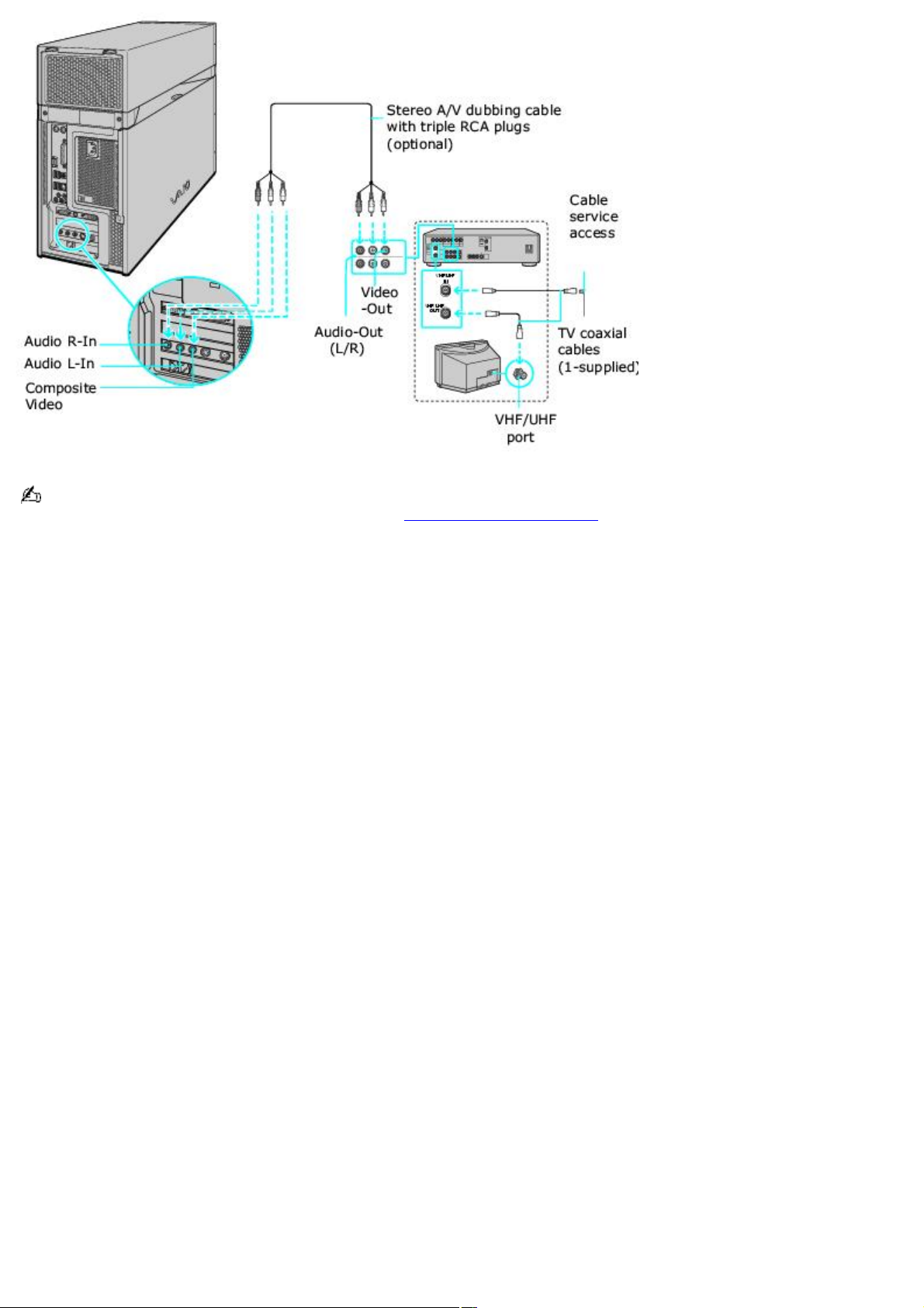
You can connect your computer to a set-top box using an S-video cable (optional) and an audio cable (optional)
instead of a stereo A/V dubbing cable (optional). See Connecting Other Devices.
Page 45
Page 46

Connecting the Remote Sensor and Remote Sensor Control
The remote sensor communicates with the Media Center remote control, enabling you to change channels and to perform
other functions. If you are using a cable or satellite set-top box, you can attach the remote sensor control which enables
you to control the set-top box with the Media Center remote control.
Page 46
Page 47

To connect the remote sensor
1.
Connect the remote sensor unit to a USB port located on either the front or back panel of your computer.
2.
Position the remote sensor to enable unobstructed communication with your remote control.
Connecting the remote sensor (back panel)
Page 47
Page 48

To connect the remote sensor control
1.
Plug the remote sensor control's cable into either jack (1 or 2) located on the back of the remote sensor.
When you attach the remote control sensor to a cable or satellite set-top box, you can control the set-top box
functions with your remote control.
Connecting the remote sensor and rem ote sensor control
* T his s upplied acc es sory may be different from the unit shown here.
2.
Remove the adhesive tape cover, located on the bottom of the remote sensor control.
3.
Press the remote sensor control onto the set-top box near the infrared port, without covering the port.
If the remote sensor control covers the infrared port on the set-top box, you cannot use the remote control
supplied with the set-top box.
Attaching the remote sensor control cable to a cable or satellite set- top box
The remote sensor unit must be visible in a line-of-sight with your remote control in order to function properly.
Page 48
Page 49

Connecting Other Devices
This section illustrates how to connect other devices to your VAIO Digital Studio® computer. Your computer has both audio
and video connection capability. You can locate the appropriate connections on the back panel or behind the lower bottom
panel on the front of the computer. You can connect a VCR or camcorder, using the composite audio In jacks. Your VCR or
camcorder may have either standard video or S-video connection capability.
Connecting a device with an audio cable
1.
Connect a dual audio cable (optional) to the composite audio L and R In jacks, located on the either the front or
rear panels of your computer.
2.
Connect the other ends of the dual audio cable to your VCR or camcorder.
Connecting a device with an S-video cable
1.
Connect an S-video cable (optional) directly into the S-video jack on either the front or back panel of your
computer.
2.
Connect the other end of the S-video cable into the appropriate port on your compatible VCR or camcorder.
Connecting a device with a stereo A/V dubbing cable
1.
Connect a stereo A/V dubbing cable with triple RCA plugs at each end (optional) directly into the composite video
port, composite audio L and R jacks, located on either the front or back panel of your computer.
2.
Connect the other ends of the stereo A/V dubbing cable into the appropriate jacks on your compatible VCR or
camcorder.
To connect a VCR or camcorder using an audio and S- v ideo cable
Page 49
Page 50
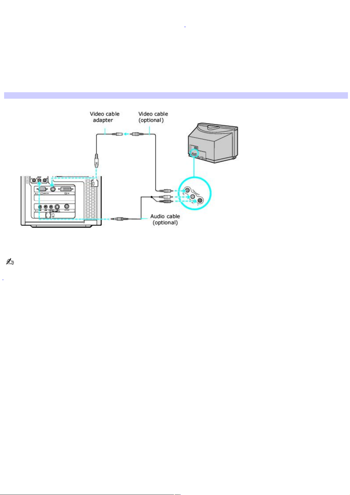
Connecting a TV monitor (display)
1.
Connect the video connector end of the video cable adapter1 to the TV Out (S-video/video) jack on the back
panel of your computer.
2.
Connect the jack end of the video cable adapter to either end of a video cable (optional). Connect the other end
of the video cable to the Video-In jack on your TV monitor or display, located on either the side or back of your TV
monitor/display.
3.
Connect the single-jack end of an audio cable (optional) to the Headphones jack located on the front or back
panel of your computer. Connect the double-jack end of the audio cable to the Audio-In (L/R) on your TV monitor
or display. (The Audio-In jacks may be located on the side or rear of your TV monitor/display.)
Connecting a TV monitor or display
The video cable adapter is not necessary, if you use an S-video cable to connect your TV to the computer's TV out
(S-video/video) jack.
1
T he video c able adapter is s upplied with c ertain V A I O c omputer models. See your c omputer's s pec ific ations s heet for information about s upplied
acc es sories.
Page 50
Page 51

Registering Your Computer
Register your computer and take advantage of Sony's commitment to quality customer support.
Page 51
Page 52

About the benefits of registering with Sony
Sony Customer Support — Communicate with a Support Representative to troubleshoot problems you may be
having with your computer.
Limited warranty — Protect your investment. See the Limited Warranty Card for more details.
You are prompted to register your computer the first time you turn on the computer. Follow the on-screen instructions to
complete the registration process. If you are not able to register your computer during the first session, you can register
your computer online at the Sony VAIO PC Registration Web site. Go to http://www.sony.com/vaioregistration.
Page 52
Page 53

Turning Off Your Computer
Follow these steps when you are ready to turn off your computer for an extended period of time.
To avoid loss of data, do not use the Power button to turn off the computer.
Page 53
Page 54

To turn off your computer
1.
Click Start in the Windows® taskbar, then select Turn Off Computer.
The Turn Off Computer dialog box appears.
2.
Select the Turn Off option.
Respond to any prompts about saving your documents.
3.
Wait for your computer to turn off automatically—the power indicator light turns off.
4.
Turn off any peripheral devices connected to your computer.
If you plan to stop using your computer for a short period of time, use Stand by mode.
Page 54
Page 55

About the power button
If your computer stops responding, press and hold the Power button for more than six seconds to force your system to
shut down. You may need to repeat this procedure if your computer does not shut down on the first attempt.
Page 55
Page 56

Using Memory Cards and Memory Card Readers
This section provides basic information about using your computer's installed memory card readers. Your computer may not
be equipped with all of the memory card readers described in this section, depending on the computer model or
configuration purchased. To view the installed hardware configuration for your computer, see the online Specifications
sheet.
About Your Memory Card Readers
Inserting a Memory Card
Removing a Memory Card
About Memory Stick Media
Sharing Memory Cards
Page 56
Page 57

About Your Memory Card Readers
Your VAIO® computer is equipped with memory card readers1 that are compatible with many popular types of memory cards.
You can use your computer's memory card readers to transfer data between digital cameras, camcorders, music players,
and other audio/video devices.
Memory cards and your com puter's m emory card readers
1
Y our c omputer may not be equipped with the memory c ard readers s hown here. T o view the ins talled memory card readers for your c omputer, s ee the online
specific ations s heet.
Page 57
Page 58

Inserting a Memory Card
The memory card readers are located on the front of your computer, behind a protective panel.
Opening the front panel cover
1.
Locate the appropriate drive for the memory card you want to use.
2.
Insert the memory card into the drive, in the direction of the arrow on the media. Do not force the card into the
drive.
If the memory card does not go into the drive easily, remove it and verify you are inserting it in the proper
direction.
Page 58
Page 59

Removing a Memory Card
The correct way to remove a memory card from a memory card reader varies, depending upon the card in use. Use care
when removing a memory card to avoid damage to the reader or card.
Do not remove a memory card while the media access indicator light is on. The card or its data may become
damaged.
To remove a Secure Digital (SD), MultiMediaCard , or xD-Picture Card media — Press the extended portion of
the memory card to release it from the drive. When the card extends, carefully remove it.
To remove a CompactFlash or Memory Stick® media — Firmly grasp the extended part of the memory card and
remove from the drive.
Page 59
Page 60

About Memory Stick Media
Memory Stick® media are a compact, portable, and versatile data storage media designed for exchanging and sharing digital
data with compatible devices. The following types of Memory Stick media are available, but compatibility with your computer
can vary.
MagicGate Memory Stick® media — Provides copyright protection with authentication and encryption, using Sony
®
MagicGate technology. Authentication ensures that protected content is only transferred between compliant devices
and media. Protected content can be recorded and transferred in an encrypted format that prevents unauthorized
duplication or playback. You can store different data formats on a single Memory Stick media.
Memory Stick PRO media — Provides MagicGate copyright protection and high-speed data transfer features
when used with compatible Memory Stick PRO devices. VAIO® computers support Memory Stick PRO media for data
storage purposes only. High-speed data transfer and MagicGate technology features, such as authentication and
encryption, may not be available. You can store different data formats on a single Memory Stick media.
Memory Stick PRO Duo media — Provides the same features and benefits of Memory Stick PRO media, in a form
that is 1/3 smaller in size.
Memory Stick® media — Provides data storage only. The Memory Stick media does not provide MagicGate
technology or high-speed data transfer. You can store different data formats on a single Memory Stick media.
Memory Stick Duo media — Provides the same features and benefits of MagicGate Memory Stick media, in a
form that is 1/3 smaller in size.
Compatibility between software programs and Memory Stick media formats may vary. At this time, Sony suggests using only
MagicGate Memory Stick media to store and transfer any data created with SonicStage or OpenMG software.
Visit the Sony online support Web site at http://www.sony.com/pcsupport regularly for the latest information on Memory
Stick® media.
Memory Stick media do not support AVI file playback directly from the media. Copy the video file to your hard disk drive
and then play back the file.
To protect data on Memory Stick media
Some Memory Stick media are equipped with a write-protect tab1. The write-protect tab prevents accidental changes to
information recorded on your Memory Stick media. When you slide the write-protect tab to the LOCK position, your Memory
Stick media is write-protected. You cannot delete, copy, or save information on the media while the write-protect tab in the
LOCK position. When you slide the tab to the un-LOCK position, you can write to or modify your Memory Stick media's
contents.
Locking the Memory Stick Media
If your computer stops recognizing your Memory Stick® media, you may have removed the media from the Memory Stick
drive before the data access process completed.
If this occurs, follow these steps:
1.
Remove the Memory Stick media from the slot.
2.
Shut down your computer, closing any open software programs, and then turn your computer off.
3.
Wait approximately 30 seconds, and then restart your computer.
Your computer recognizes the Memory Stick media, when you insert it into the Memory Stick slot again.
1
Some Memory Stick media do not have a write-protect tab, or the write-protec t tab is in a different loc ation. For details about us ing your M emory Stic k
media, see the supplied information sheet.
Page 60
Page 61

Sharing Memory Cards
If you plan to share your memory card between your VAIO® computer and devices such as a digital camera or music player,
the card must be formatted properly.
Format the memory card by using it in the device first. See the information supplied with the device for details how
to format the memory card.
If your device does not recognize memory card that has been formatted by your computer, follow these steps:
1.
Save the card's contents to your hard disk drive.
2.
Reformat the memory card using the device, not your computer.
Page 61
Page 62

Upgrading and Maintaining your VAIO Computer
In the future you may want to increase the functionality of your VAIO computer. This section describes how to perform basic
upgrades and maintenance on your computer.
Overview
About Opening the Computer
About Closing the Computer
About Add-on Card Installation
Installing Memory
About the Lithium Battery
About Hard Disk Drive Installation
Page 62
Page 63

Overview
The upgrading procedures described in this section assume that you are familiar with the general terminology associated
with personal computers, safety practices, required regulatory compliances, and the modification of electronic equipment.
Page 63
Page 64

Before upgrading your computer
Disconnect the computer from its power source and from telecommunications links, networks, or modems before you open
the unit or follow any procedures described in this section.
Failure to disconnect your computer from its power source may result in personal injury or equipment damage.
Always turn the power off before you open the computer or connect your computer to peripheral equipment.
Otherwise, damage may occur to the integrated circuits.
Your computer may not be equipped with all of the hardware features mentioned in this section. The interior hardware
configuration of your computer may vary from the illustrations, depending on the computer purchased. To view the specific
hardware configuration for your computer, see the online specifications sheet.
You may need to temporarily remove add-on cards or other components that may be near the slot cover you plan to
remove.
Electrostatic discharge (ESD) can damage disk drives, add-on cards, and other components. Follow the
procedures described here only at an ESD workstation. If such a station is not available, do not work in a carpeted
area and do not handle materials that produce or hold static electricity (for example, cellophane wrappers). Ground
yourself by maintaining continuous contact with an unpainted metal portion of the chassis while performing the
procedure.
Page 64
Page 65

About Opening the Computer
Removing the top cover
1.
Shut down your computer and turn off all peripheral devices, such as your printer.
2.
Unplug your computer and disconnect any peripheral devices.
3.
Locate the two tabs on the top edge of the back panel.
4.
Gently lift these tabs and slide the top cover towards the back of the unit.
5.
Lift the top cover up and set aside.
Remov ing the top cov er
If you open the cover or panels immediately after you shut down your computer, the components may be too
hot to touch. Wait until the internal parts of the computer cool down before you attempt to open the unit.
Page 65
Page 66

About Opening the Computer
Removing the top cover
1.
Shut down your computer and turn off all peripheral devices, such as your printer.
2.
Unplug your computer and disconnect any peripheral devices.
3.
Locate the two tabs on the top edge of the back panel.
4.
Gently lift these tabs and slide the top cover towards the back of the unit.
5.
Lift the top cover up and set aside.
Remov ing the top cov er
If you open the cover or panels immediately after you shut down your computer, the components may be too
hot to touch. Wait until the internal parts of the computer cool down before you attempt to open the unit.
Page 66
Page 67

Removing the side panel
1.
Shut down your computer and turn off all peripheral devices, such as your printer.
2.
Unplug your computer and disconnect any peripheral devices.
3.
Press the release button on the top edge of the side panel.
Remov ing the side panel
4.
Lift the side panel away from the unit and set aside.
Page 67
Page 68

About Closing the Computer
Replacing the side panel
1.
Align the tabs on the bottom of the side panel to the tracks on the edge of the chassis frame.
2.
Gently press the side panel against the chassis, until the release button locks the panel back into place.
Replacing the side panel
Page 68
Page 69

About Closing the Computer
Replacing the side panel
1.
Align the tabs on the bottom of the side panel to the tracks on the edge of the chassis frame.
2.
Gently press the side panel against the chassis, until the release button locks the panel back into place.
Replacing the side panel
Page 69
Page 70

Replacing the top cover
1.
Align the tracks on the top cover to the tracks on the chassis frame.
2.
Gently slide the top cover forward onto the chassis, until the back panel tabs lock the panel into place.
Replacing the top cover
Page 70
Page 71

About Add-on Card Installation
Your computer may have one or more open expansion slots, depending on the model configuration. An expansion slot
enables you to install add-on cards to expand the functionality of your computer. The length of the add-on card should not
exceed 9.05 inches.
Add-on card configuration varies by model. Some models, such as Configure-to-Order (CTO) computers, may have all
expansion slots filled.
Observe the proper safety precautions when you add cards to your Sony computer. See Before upgrading your
computer.
Page 71
Page 72

Installing an add-on card
1.
Shut down your computer and turn off all peripheral devices, such as your printer.
2.
Unplug your computer and any peripheral devices.
3.
Gently place the unit on its side and remove the side panel. See About Opening the Computer
4.
Locate an available expansion slot. Remove the slot cover's screw, and then remove the slot cover.
When removing a slot cover, be careful not to damage components on the system board or add-on
cards. You may need to temporarily remove add-on cards or other components that may be next to the slot cover
you want to remove.
Remov ing the slot cov er
5.
Install the add-on card by inserting it into the expansion slot and secure it with the screw from the expansion
slot cover.
Installing an add-on card
Page 72
Page 73
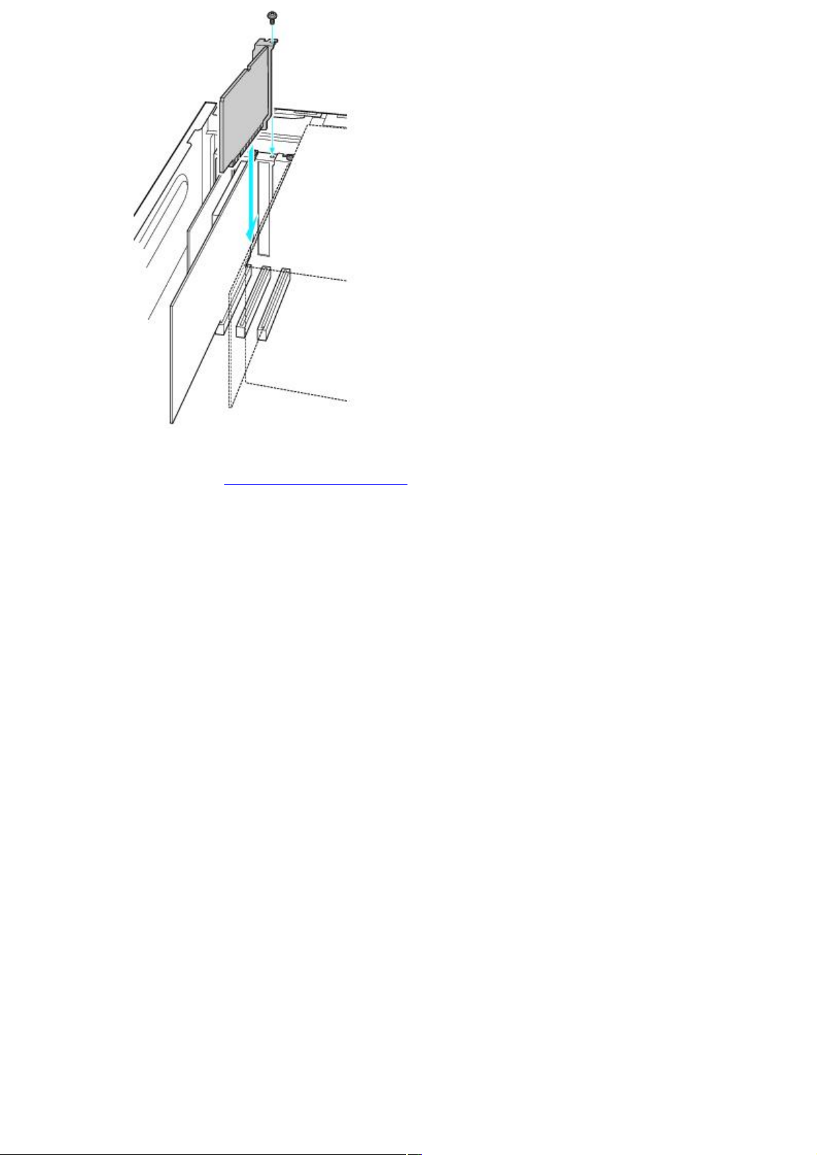
6.
Attach any internal cables that the card requires. See the instructions supplied with the add-on card.
7.
Replace the side panel. See About Closing the Computer.
8.
Reconnect the power cord and all peripheral devices.
9.
Turn on the computer.
Page 73
Page 74

Installing Memory
The amount of preinstalled memory may vary, depending on the computer purchased. Your computer may ship with all
available memory slots filled. For memory replacement or upgrades, use the correct memory module for your computer's
configuration. See the online Specifications sheet for details about the memory installed in your computer.
You can purchase additional memory modules, accessories, and peripheral equipment from your local retailer.
Observe the proper safety precautions when you add or remove the memory in your computer. See Before
upgrading your computer.
Page 74
Page 75
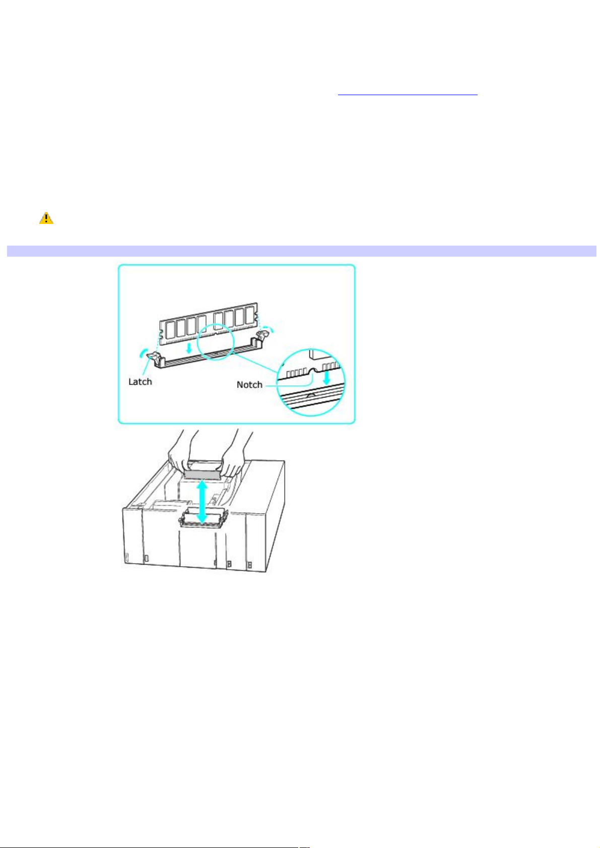
Removing a memory module
1.
Shut down your computer and turn off all peripheral devices, such as your printer.
2.
Unplug your computer and all peripheral devices.
3.
Gently place the unit on its side and remove the side panel. See About Opening the Computer
If necessary, remove any cables, add-on cards, or other components to access the memory module slots.
4.
Locate the memory module(s) you wish to remove.
5.
Push down on the latches, located on both sides of the module, to gently eject it from the slot.
6.
Grasp one edge of the module and lift it out. Store the module in a static-free bag.
Gently handle the memory module by the sides only. Avoid touching the pins located at the bottom edge
of the module.
Remov ing/Installing m emory
Page 75
Page 76

Installing a memory module
1.
Shut down your computer and turn off all peripheral devices, such as your printer.
2.
Unplug your computer and any peripheral devices.
3.
Gently place the unit on its side and remove the side panel. See About Opening the Computer
If necessary, remove any cables, add-on cards, or other components to access the memory module slots.
4.
Remove the memory module from its anti-static package, handling it by the the edges.
5.
Locate the notch on the bottom edge of the module and align it over the open memory slot.
6.
Firmly insert the bottom edge of the memory module into the slot.
7.
Press down evenly against the module's upper corners. The end latches snap into position, holding the module
in place.
To avoid damaging a memory module slot, move the end latches slightly outward to relieve pressure.
The module clicks into place.
8.
Reinstall any components or add-on cards you may have removed.
9.
Replace the side panel. See About Closing the Computer.
Page 76
Page 77

About the Lithium Battery
The lithium battery starts to weaken after several years and the system settings, such as the date and time stored in
CMOS RAM, may become inaccurate. Replace the lithium battery when this occurs.
There is danger of the battery exploding if it is replaced incorrectly. Replace the battery only with a
CR2032-type lithium battery.
Page 77
Page 78

Replacing the lithium battery
1.
Write down any changes you may have made to the settings in the BIOS Setup utility.
2.
Shut down your computer and turn off all peripheral devices, such as your printer.
3.
Unplug your computer and the peripheral devices.
4.
Gently place the unit on its side and remove the side panel. See About Opening the Computer
If necessary, remove any cables, add-on cards, or other components to access the lithium battery.
5.
Gently push the battery holder's tab away from the battery and remove the battery from the holder.
6.
Install the new battery with the plus (+) side facing the battery holder tab.
Installing a lithium battery
7.
Replace the side panel. See About Closing the Computer.
The values stored in the CMOS memory are now reset to the factory default values. Run the Setup utility to reset the date,
time, passwords, and other changes you may have made to the BIOS settings. If you do not wish to customize your BIOS
settings, do not run the Setup utility.
Dispose of the lithium battery properly. In some areas, the disposal of lithium batteries in household or
business trash may be prohibited. You can return your unwanted lithium batteries to your nearest Sony Service Center
or Factory Service Center. To locate a Service Center near you, visit the Sony online support Web site at
http://www.sony.com/pcsupport.
Page 78
Page 79

Resetting the computer's date and time
To reset your computer's date and time:
1.
Double-click the time readout displayed in the Windows® Taskbar Notification area. The Date and Time
properties window appears.
2.
From the Date & Time tab, change the settings as desired. Click Apply, and then click OK.
Page 79
Page 80

About Hard Disk Drive Installation
Your computer may be equipped with open internal bays to hold additional 3.5-inch hard disk drives. When you install an
additional hard disk drive, the method of attaching connectors and cables may be different from the instructions described
in this section. Review the manufacturer's information provided with your new hard disk drive before attempting to install it
in your computer.
Certain models are configure-to-order (CTO) computers that may already have additional hard disk drives installed
that support the Redundant Array of Independent Disks (RAID) technology. See the About RAID Systems section.
The installation information provided in this section may not apply if you have purchased a VAIO® computer that supports
RAID.
Page 80
Page 81

Replacing the original hard disk drive
If you replace the original, factory-installed hard disk drive, you may need to correct your drive mapping, create a VAIO
Recovery Media Kit, or visit the Sony online support Web site for more information.
About drive mapping
When a new hard disk drive is installed, the original drive mapping1 may be changed. The identified drives, including those
for removable media2, may not reflect correct drive/icon associations. For more information on how to correct your drive
mapping, visit the Sony online support Web site at http://www.sony.com/pcsupport.
About hard disk drive recovery
When you replace the original hard disk drive, the preinstalled VAIO Recovery Wizard utility program cannot restore the
drive partitions, operating system, or original software programs. Before replacing the hard disk drive, create a VAIO
Recovery Media Kit or purchase a kit from Sony.
Your VAIO® computer is not supplied with System or Application Recovery CDs. Use the VAIO Recovery Wizard utility to
recover your computer's operating system and preinstalled software programs.
For more information about the VAIO Recovery Wizard utility program:
1.
Click Start from the Windows® taskbar, and then click Help and Support.
2.
From the VAIO Help and Support Center, click VAIO Recovery Options.
Observe the proper safety precautions when you upgrade your Sony computer. See Before upgrading your
computer.
Drive letter assignment
When a new hard disk drive is installed, an identifying drive letter is assigned. The drive letter assignment becomes
effective after you register for the first time or after recovering your computer with the VAIO® Recovery Wizard utility
program.
The Click to DVD software program creates a new folder location on the new hard disk drive. This new folder is the default
location to save files created with Click to DVD software.
If the Microsoft® Windows® operating system identifies the new hard disk drive as drive D, the Click to DVD software
program saves its files to a new folder on the new drive D.
If the Windows operating system assigns another letter to the new hard disk drive, such as drive E or J, the Click to
DVD software program creates the new save folder on the new drive.
When you start Click to DVD software for the first time, after recovering the computer or installing a new hard disk
drive, the software program automatically creates a new save folder on the new drive.
Before you install a new hard disk drive
If your computer is equipped with a Serial ATA (SATA) hard disk drive, you do not need to configure the new drive.
The instructions provided here do not apply, if you want to set up a RAID configuration.
Follow the configuration instructions supplied with your new hard disk drive.
See your computer's specifications sheet for details about the installed hard disk drive.
1
Drive mapping refers to the assignment of an identifying letter to a specific drive, s uc h as Drive C or Drive D which identify the original hard disk drive.
2
Y our c omputer may be equipped with other memory c ard readers , for media s uc h as M emory Stick®, SD media, C ompac tFlash®, or M icrodrive c ards . See
the online Specification s heet for more information about your c omputer's memory c ard reader c onfiguration.
Page 81
Page 82
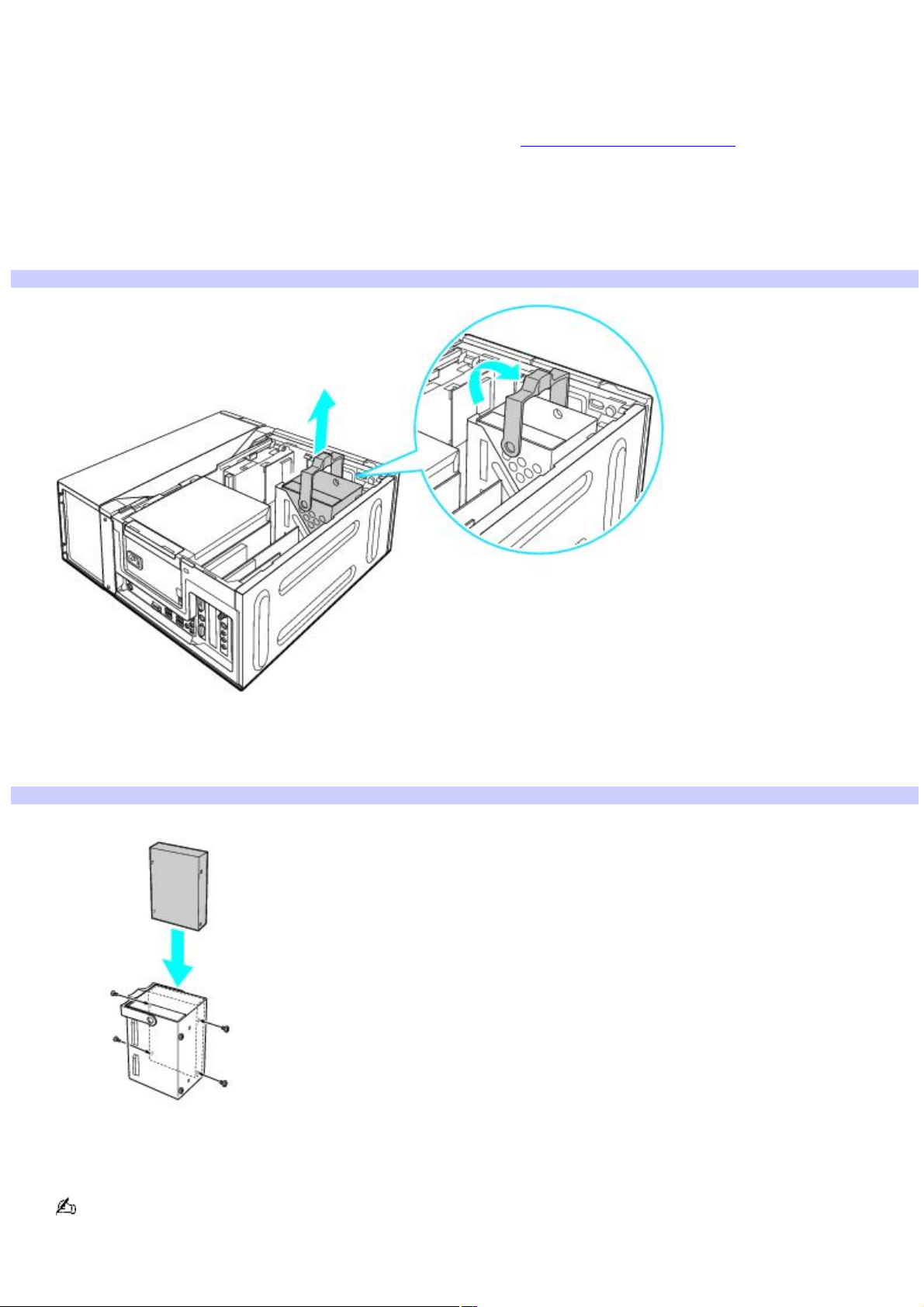
Installing an additional hard disk drive
1.
Shut down your computer and turn off all peripheral devices, such as your printer.
2.
Unplug your computer and any peripheral devices.
3.
Gently place the unit on its side and remove the side panel. See About Opening the Computer
4.
Detach the power and interface cables from the original hard disk drive that is preinstalled in your computer.
5.
Unlock the drive holder from the chassis by lifting the drive holder handle straight out from the unit.
6.
Use the handle to slide the drive holder out.
Remov ing the driv e holder
7.
Slide the new drive into the drive holder and align the holes on each side of the drive bay.
8.
Secure the drive to the drive holder with screws, through the holes on each side of the drive holder.
Attaching the drive screws
Your new hard disk drive is supplied with the necessary screws. Do not overtighten these screws when securing
the drive to the drive holder.
9.
Align the drive holder with the tracks on the inside of the chassis. Slide the drive holder in completely.
Page 82
Page 83
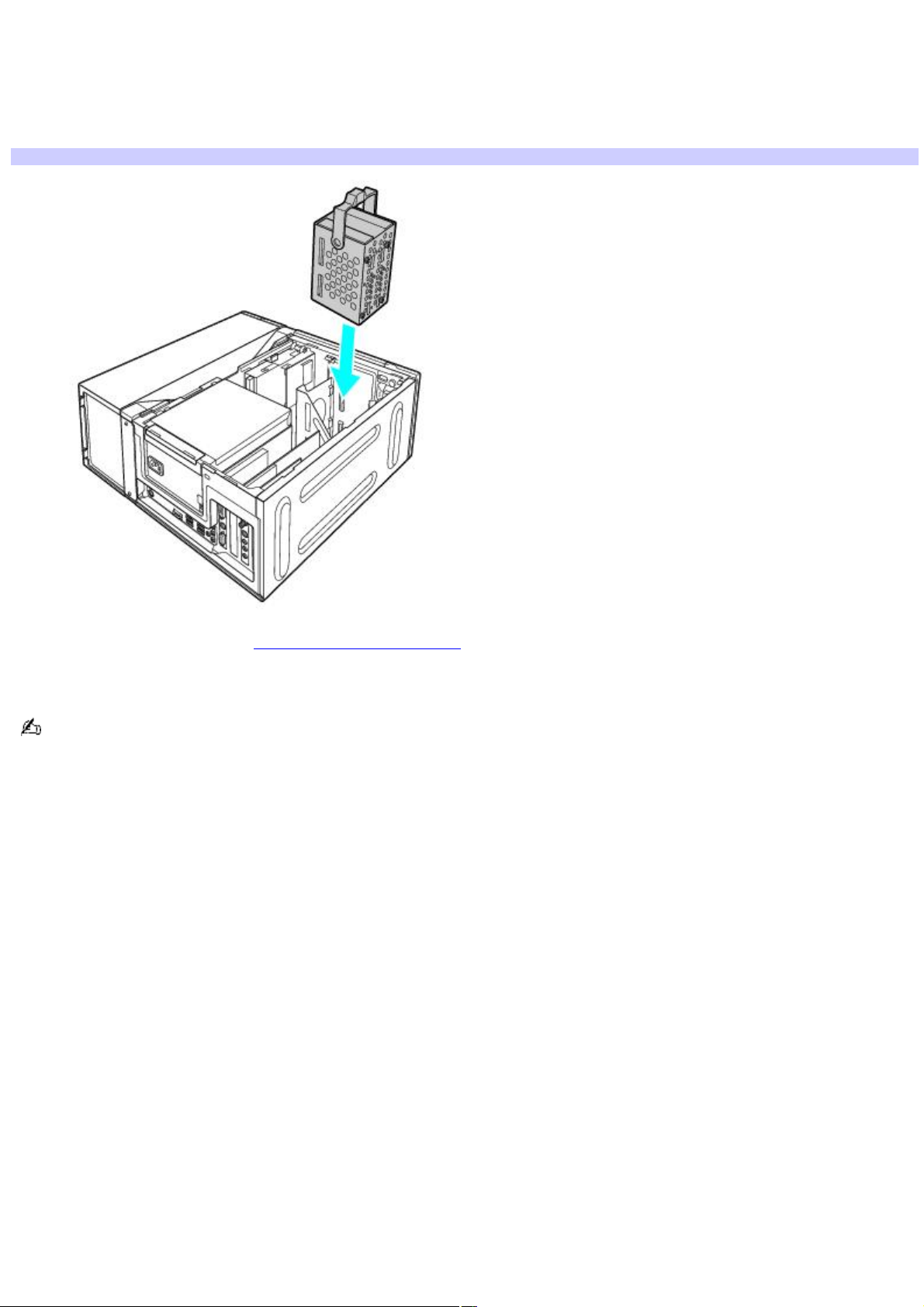
10.
Push the drive holder handle down to lock the drive into position.
11.
Reconnect the SATA and power connectors to the original drive.
12.
Connect another SATA interface cable between the new drive and an unused SATA port on the motherboard.
13.
Connect the second power connector to the new drive following the instructions supplied with the drive.
Replacing the drive holder
14.
Replace the side panel. See About Closing the Computer.
15.
Reconnect the power cord to your computer.
The hard disk drive access light blinks when either internal hard disk drive is active.
Page 83
Page 84

Identifying the additional hard disk space
When you initialize the new hard disk, it must be configured as an extended partition in Windows NT file system (NTFS)
format.
1.
Log on to Windows® as Administrator.
2.
Click Start in the Windows taskbar, then right-click My Computer. A shortcut menu appears.
3.
Select Manage. The Computer Management window appears.
4.
Under the file directory on the right, go to Storage and then select Disk Management.
5.
Right-click on the newly installed, unformatted hard disk (Disk label identified with red marking). From the
shortcut menu, select Initialize Disk.
6.
Click on the Unallocated area of the disk and then right-click to display a shortcut menu.
7.
Select New Partition. The New Partition wizard appears.
8.
Follow the wizard's on-screen instructions to complete the process.
The Windows® XP operating system recognizes the new hard disk drive and applies the NTFS format.
Page 84
Page 85

About RAID Systems
When multiple hard disk drives are combined, they can provide an affordable answer to your VAIO® computer's performance
or security requirements. This solution is called a Redundant Array of Independent Disks1 (RAID). RAID or RAID-ready
capability is available only for configure-to-order (CTO) computer systems. See your computer's specifications sheet for
details on your computer's hardware configuration.
A RAID Overview
About RAID Levels
Configuring a RAID Array
RAID Glossary
1
A lso known as "Redundant A rray of Inexpens ive Dis ks".
Page 85
Page 86

A RAID Overview
If you have purchased a configure-to-order (CTO) VAIO® computer with one of the following options:
RAID-0 —Your computer is configured for RAID-0 and has two or more preinstalled S-ATA hard disk drives.
RAID-ready —Your computer has RAID capability and requires you to install one or more S-ATA hard disk drives.
In either situation, you can:
Install and configure hard disk drives for RAID-0 or RAID-1.
Change the existing RAID configuration to RAID-0 or RAID-1.
Remove the RAID configuration completely.
Your VAIO computer's drive bay can accommodate a total of four S-ATA hard disk drives. If you are installing your own
equipment, Sony suggests using hard disk drives that are identical in size and manufacture.
Page 86
Page 87

Reasons for using a RAID array system
When hard disk drives are grouped together in a RAID array, they are configured, formatted, and managed to perform in a
specific way. Your computer's data is spread across these drives in a manner that determines the level of RAID performance
and protection. The level of RAID protection and redundancy determines the capacity of the array, the security of your data,
and the quality of your computer's overall performance.
To aid your understanding of RAID terminology, see the RAID Glossary.
You may decide that a RAID array meets your needs when:
Your computer's data needs increased fault tolerance to protect against interruptions or hardware failure.
Your computer performs intensive work, such as video or graphics design, and require improved computing speed.
Page 87
Page 88

RAID array organization
A single hard disk drive has two basic functions — writing and reading data. These functions are handled differently when
using a RAID array.
A RAID array is organized from the physical drives into a physical array. (The hard disk drives are combined into the array.)
These physical arrays are then formatted into a single, logical drive, which communicates with your computer. This
organization enables your computer to use the RAID array as a single hard disk drive.
Page 88
Page 89

About RAID Levels
RAID is intended to protect data and create fault tolerance. Important factors such as availability, reliability, fault tolerance,
and performance, are essential to selecting a RAID level that meets your computing needs.
Page 89
Page 90

RAID-0
This RAID level uses striping without parity. Striping breaks data into small pieces and then simultaneously writes or reads
to multiple locations. This increases your computer's performance and data storage capacity.
RAID- 0: Striping without parity
Best uses for RAID-0
This RAID level is appropriate for situations where read/write performances is more important than data security. Some
examples are environments that use high bandwidth software programs for video production, video editing, or pre-press
production.
RAID-0 limitations
RAID-0 does not provide fault tolerance. All computer data on the array is lost if a single drive in the physical array fails. This
RAID level is not a true RAID configuration, as it does not provide redundancy. When using a RAID-0 array, your data
storage capacity may be increased, but is limited to twice the size of the smallest hard disk drive in the array. As an
example, if your array uses a 60 GB drive and a 20 GB drive, your total hard disk drive volume is 40 GB.
Page 90
Page 91

RAID-1
This RAID level uses mirroring. Mirroring writes all data onto each hard drive in the RAID array, in exactly the same way.
Your computer's reading performance is improved, while writing performance is slower, in comparison to a single hard disk
drive. RAID-1 is the simplest redundant array to set up, as only two hard disk drives are required. Full fault tolerance is
provided in the event of a single hard disk drive failure, as all data is still available in the other, mirrored hard disk drive.
If a single hard disk drive fails (RAID-1), the remaining, functioning hard disk drive continues to operate without fault
tolerance until the failed drive is replaced and mirroring is restored.
RAID- 1: Mirroring
Best uses for RAID-1
RAID-1 is appropriate for situations where data availability and performance are important. In environments where finance
or payroll software programs are used, fault tolerance may be more important than capacity.
RAID-1 limitations
A RAID-1 (mirrored) volume is approximately the size of the smaller hard disk drive. This may not be a cost-effective
solution, if data storage capacity is a concern. Your computer's write performance is slower, because two write commands
are generated to direct the data to two separate hard disk drive locations.
Page 91
Page 92

Configuring a RAID Array
Certain VAIO® computers are available for purchase as RAID-0 or RAID-ready. The number of preinstalled S-ATA hard disk
drives can vary, depending on the hardware configuration purchased. These computers are configured-to-order (CTO),
based on your hardware requirements. See your computer's specification sheet for details about your specific hardware
configuration.
If you purchase a RAID-0 computer:
You can change the RAID-0 configuration to RAID-1.
You can remove RAID configuration completely and use each individual drive separately.
If you purchase a RAID-ready computer:
You can install an additional drive(s) and set up a RAID-0 or RAID-1 configuration.
You can choose to use any additional drive(s) as a separate drive, without RAID configuration.
If you have purchased a RAID-ready computer that does not have additional hard disk drives preinstalled, install the
additional S-ATA hard disk drives* required to enable RAID capability. See the instructions provided in the About Hard Disk
Drive Installation section.
* U s e identic al hard dis k drives , if pos s ible.
Page 92
Page 93

Before getting started
Back up your computer's data to external media. Creating, altering, or configuring for RAID deletes all data from
affected hard disk drives.
Create a VAIO Recovery Media Kit, so that you can configure the RAID volumes, and perform a hard disk drive
recovery.
For more information about creating recovery media using the VAIO Recovery Wizard utility program:
1.
Click Start from the Windows® taskbar, and then click Help and Support.
2.
From the VAIO Help and Support Center, click VAIO Recovery Options.
Verify the status of the existing hard disk drive(s) before creating or changing the RAID volume. Use the Intel
®
Storage Utility software program to check drive. See the section, About the Intel Storage Utility program.
The VAIO Recovery Wizard utility program can configure the first two hard disk drives into a RAID-0 (striped) or RAID-1
(mirrored) volume. (Hard disk drives are installed in port-0 and port-1). Use the Intel® Application Accelerator (IAA) feature
of the Intel Storage Utility software program, to configure any additional drives. See the section, About the Intel Storage
Utility program.
Page 93
Page 94
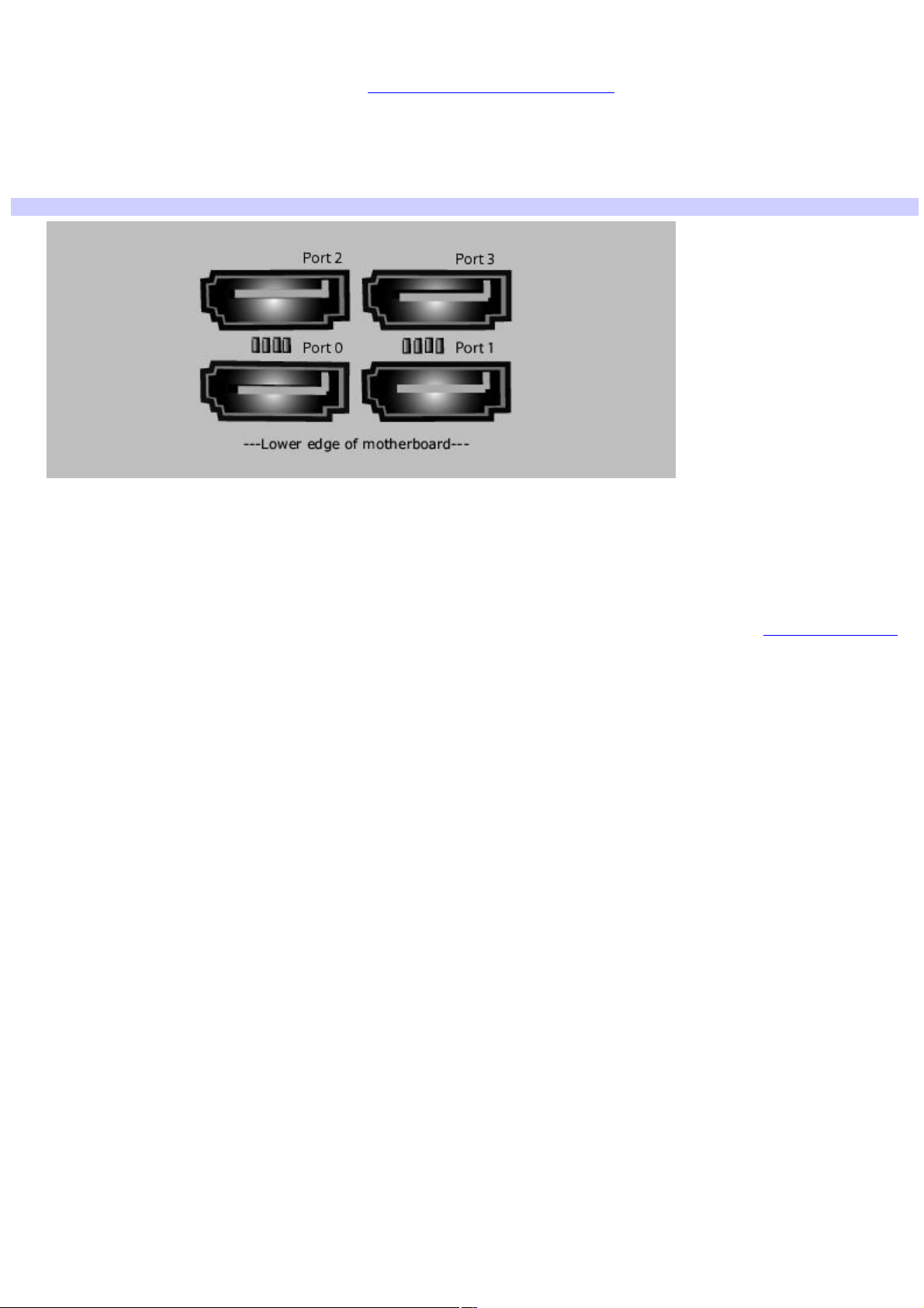
Installing additional hard disk drives
If you have purchased a RAID-ready computer, you may be required to install an additional drive(s). You can find details
about installing additional hard disk drives in the About Hard Disk Drive Installation section.
1.
Place all S-ATA hard disk drives into the drive holder inside the computer's chassis.
2.
Connect one end of the S-ATA data cable(s) to the S-ATA connection, starting with Port-0 on the motherboard.
Connect the data cables of any additional drives to Ports 1, 2, and then 3.
Motherboard - detail
3.
Connect the other end of the S-ATA data cable(s) to the corresponding S-ATA hard disk drive.
4.
Connect the S-ATA power cable(s) to the corresponding S-ATA hard disk drive.
If your hard disk drive is equipped with two power connectors, connect the S-ATA power cable. See the
information supplied with your hard disk drive for details on proper power connections.
When all additional hard disk drives are installed, you are ready to configure the RAID volume. See the About RAID Levels
section for brief descriptions of RAID-0 and RAID-1 levels.
Page 94
Page 95
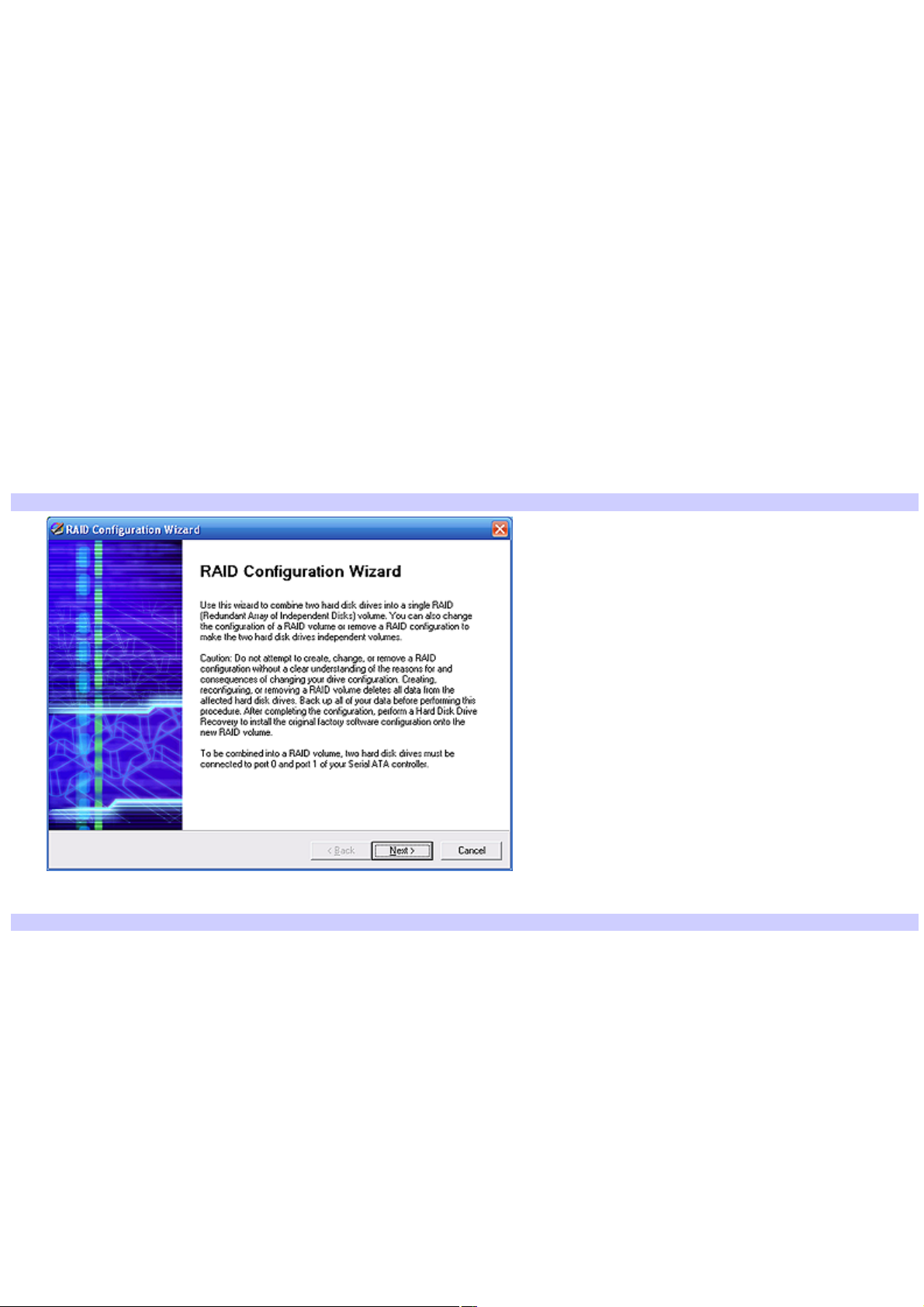
Using the RAID Configuration Wizard
The RAID Configuration Wizard can configure two installed hard disk drives for RAID-0 or RAID-1 levels. You can also use the
RAID Configuration Wizard to change your computer's RAID array to RAID-0 or RAID-1.
1.
Press the power switch on the computer to turn on the computer.
2.
Open the optical drive, and place the Startup Recovery Disc from the Recovery Media Kit into either optical
drive.
3.
Close the drive and turn off your computer.
4.
Wait approximately 30 seconds, and then turn on the computer again.
5.
When prompted, insert Recovery Disk 1 into the optical drive, and then click OK.
The VAIO Recovery Wizard appears.
6.
Click Next.
7.
Select Custom Recovery (for Advanced Users), and click Next.
8.
Select RAID Configuration, and click Next.
The RAID Configuration Wizard appears.
RAID Configuration Wizard
9.
Click Next. The RAID Configuration Options window appears.
RAID Configuration Options
Page 95
Page 96
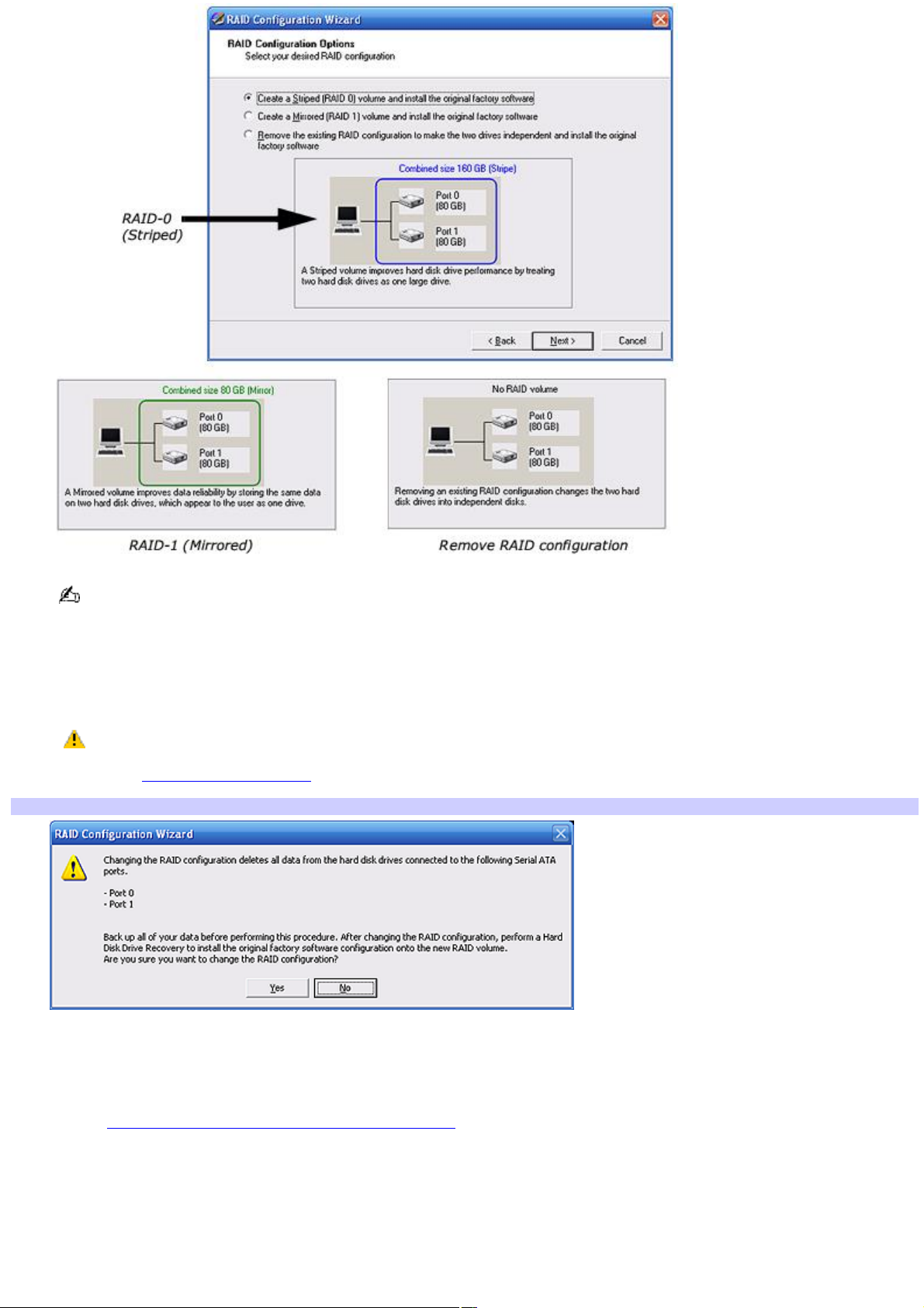
If you are using hard disk drives that vary in size, note that the RAID configuration is set to the size of the
smallest drive.
10.
Select one of the three options, and click Next.
A final confirmation message appears.
If you have not performed a back up of your computer's data, or you do not want to continue
with the RAID configuration, respond to the final confirmation message by clicking "No" and exit the wizard. See
the section, Before getting started, for advice on how to prepare for RAID configuration.
RAID Configuration Wizard - Final confirm ation m essage
11.
Click Yes to configure your RAID array.
12.
Do not remove the VAIO Recovery Media Kit disc from your computer's optical disc drive. Click Restart to start the
VAIO Recovery Wizard utility program.
See the Using the VAIO Recovery Wizard utility program section for more information.
Page 96
Page 97

Using the VAIO Recovery Wizard utility program
A complete hard disk drive recovery restores the original, factory settings and recovers all of the preinstalled software
programs.
1.
From the VAIO Recovery Wizard main window, click Next.
2.
Select Custom Recovery (for Advanced Users), and click Next.
3.
Select either option, as shown below, and then click Next.
Complete Recovery with the Recovery Drive (Recommended)
Complete Recovery without the Recovery Drive
4.
If installation messages and prompts appear, follow the instructions provided by each installation wizard and
respond to each prompt or message.
Your computer may restart during this process.
5.
When the optical disc drive opens, remove the disc and close the drive door. Click Next.
Your computer may restart several times before it becomes available for use.
Page 97
Page 98
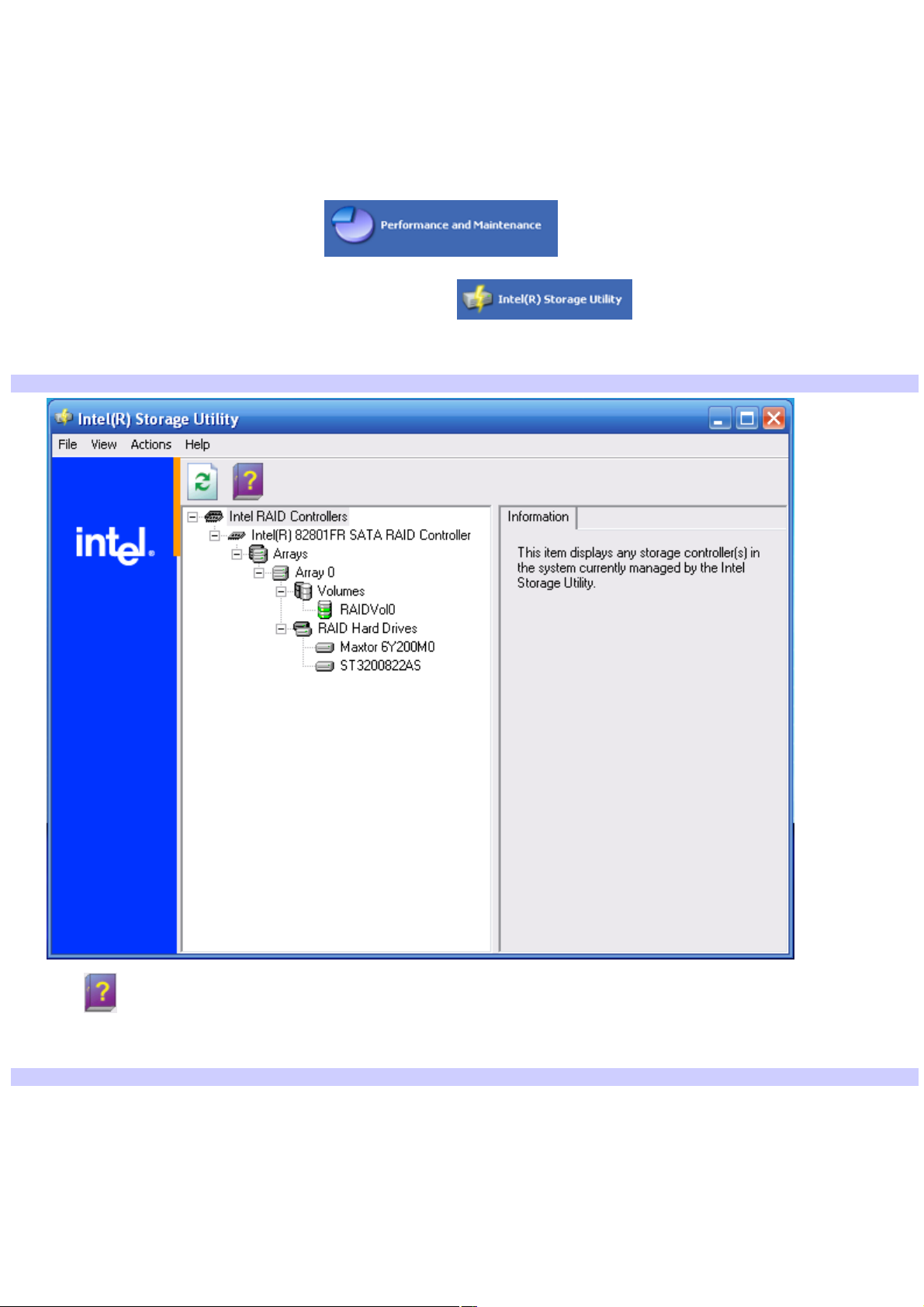
About the Intel Storage Utility program
You can find information about RAID volume configuration in the Intel® Storage Utility program. This utility program contains
the Intel® Application Accelerator RAID edition feature.
Locating the Intel Storage Utility program
1.
Click Start from the Windows® taskbar, and then click Control Panel.
2.
From the Control Panel window, click .
3.
From the Performance and Maintenance window, click .
The Intel® Storage Utility main window appears.
Intel® Storage Utility
4.
Click to open Help.
The Intel® Application Accelerator Help introduction window appears.
Intel® Application Accelerator Help
Page 98
Page 99

The Intel® Application Accelerator Help file provides basic information on setting up additional hard disk drives as
a RAID array. You can find more information on this topic at http://support.intel.com/support/go/iaa/kb_r.htm.
Page 99
Page 100

RAID Glossary
This glossary contains some basic terms that may aid your understanding of RAID technology.
Term Definition
Array Two or more hard disk drives that are grouped together and function as a single drive to the
host computer.
Fault tolerance The ability of a computer to continue its function, even after one or more hard disk drives have
failed.
Intel® Application Accelerator RAID edition (IAA) Software program that replaces the original ATA drivers provided with
the Microsoft® Windows® operating system. The IAA replacement drivers are optimized for computers using certain Intel
®
chipsets.
Logical drive Two or more hard disk drives that are grouped together so that they appear and function as a
single or logical drive to the host computer.
Mirrored/Mirroring All data on a primary hard disk drive is duplicated on a secondary drive, to provide data
protection.
Parity A type of data protection that uses verification to detect errors in data.
Physical drive The actual hard disk drive.
RAID An acronym for "Redundant Array of Independent Disks". This method of combining small,
inexpensive hard disk drives offers advantages for data availability, equipment cost, and system performance.
RAID-0 See "Striped/Striping"
RAID-1 See "Mirrored/Mirroring"
Redundant
(Information Technology use) Additional computer components, such as hard disk drives, that are installed to back
up the primary resources in case of failure.
S-ATA An acronym for "Serial Advanced Technology Attachment." This is a standard uses serial
signaling technology and is used for connecting hard disk drives into computers.
Striped/Striping Data is spread evenly over multiple hard disk drives for improved system performance. There
is no data protection.
Page 100
 Loading...