

Sony UP-D898MD, UP-X898MD Service Manual

DIGITAL GRAPHIC PRINTER
UP-D898MD
HYBRID GRAPHIC PRINTER
UP-X898MD
SERVICE MANUAL
1st Edition

!警告
このマニュアルは,サービス専用です。
お客様が,このマニュアルに記載された設置や保守,点検,修理などを行うと感電や火災,
人身事故につながることがあります。
危険をさけるため,サービストレーニングを受けた技術者のみご使用ください。
! WARNING
This manual is intended for qualifi ed service personnel only.
To reduce the risk of electric shock, fi re or injury, do not perform any servicing other than that
contained in the operating instructions unless you are qualifi ed to do so. Refer all servicing to
qualifi ed service personnel.
! WARNUNG
Die Anleitung ist nur für qualifi ziertes Fachpersonal bestimmt.
Alle Wartungsarbeiten dürfen nur von qualifi ziertem Fachpersonal ausgeführt werden. Um die
Gefahr eines elektrischen Schlages, Feuergefahr und Verletzungen zu vermeiden, sind bei
Wartungsarbeiten strikt die Angaben in der Anleitung zu befolgen. Andere als die angegeben
Wartungsarbeiten dürfen nur von Personen ausgeführt werden, die eine spezielle Befähigung
dazu besitzen.
! AVERTISSEMENT
Ce manual est destiné uniquement aux personnes compétentes en charge de l’entretien. Afi n
de réduire les risques de décharge électrique, d’incendie ou de blessure n’effectuer que les
réparations indiquées dans le mode d’emploi à moins d’être qualifi é pour en effectuer d’autres.
Pour toute réparation faire appel à une personne compétente uniquement.
UP-D898MD/X898MD

注意
[For UP-X898MD]
注意
指定以外の電池に交換すると,破裂する危険があります。
必ず指定の電池に交換してください。
使用済みの電池は,国または地域の法令に従って
処理してください。
CAUTION
Danger of explosion if battery is incorrectly replaced.
Replace only with the same or equivalent type recommended by the manufacturer.
When you dispose of the battery, you must obey the
law in the relative area or country.
ATTENTION
Il y a danger d’explosion s’il y a remplacement incor-
rect de la batterie. Remplacer uniquement avec
une batterie du même type ou d’un type équivalent
recommandé par le constructeur.
Lorsque vous mettez la batterie au rebut, vous devez
respecter la législation en vigueur dans le pays ou la
région où vous vous trouvez.
FÖRSIKTIGHET!
Fara för explosion vid felaktigt placerat batteri.
Byt endast mot samma eller likvärdig typ av batteri,
enligt tillverkarens rekommendationer.
När du kasserar batteriet ska du följa rådande lagar
för regionen eller landet.
PAS PÅ
Fare for eksplosion, hvis batteriet ikke udskiftes
korrekt.
Udskift kun med et batteri af samme eller tilsvarende
type, som er anbefalet af fabrikanten.
Når du bortskaffer batteriet, skal du følge
lovgivningen i det pågældende område eller land.
HUOMIO
Räjähdysvaara, jos akku vaihdetaan virheellisesti.
Vaihda vain samanlaiseen tai vastaavantyyppiseen,
valmistajan suosittelemaan akkuun.
Noudata akun hävittämisessä oman maasi tai
alueesi lakeja.
VORSICHT
Explosionsgefahr bei Verwendung falscher Batterien.
Batterien nur durch den vom Hersteller empfohlenen
oder einen gleichwertigen Typ ersetzen.
Wenn Sie die Batterie entsorgen, müssen Sie die
Gesetze der jeweiligen Region und des jeweiligen
Landes befolgen.
FORSIKTIG
Eksplosjonsfare hvis feil type batteri settes i.
Bytt ut kun med samme type eller tilsvarende
anbefalt av produsenten.
Kasser batteriet i henhold til gjeldende avfallsregler.
注意
如果更换的电池不正确,就会有爆炸的危险。
只更换同一类型或制造商推荐的电池型号。
处理电池时,必须遵守相关地区或国家的法律。
UP-D898MD/X898MD
1 (P)


Table of Contents
Manual Structure
Purpose of this manual ............................................................ 3 (E)
Related manuals ...................................................................... 3 (E)
Trademarks .............................................................................. 3 (E)
1. Service Overview
1-1. Service Flow Chart .................................................... 1-1 (E)
1-1-1. Flow Chart before Service ............................... 1-1 (E)
1-1-2. Flow Chart after Service .................................. 1-3 (E)
1-2. Precaution for Transporting .......................................1-4 (E)
1-3. Board Location and Main Parts Location .................1-5 (E)
1-3-1. Board Location ................................................1-5 (E)
1-3-2. Main Parts Location ......................................... 1-5 (E)
1-3-3. Sensor Location ...............................................1-6 (E)
1-4. Tightening torque ...................................................... 1-6 (E)
1-5. Removing/Installing the Cabinet ............................... 1-7 (E)
1-5-1. Top Cover ........................................................ 1-7 (E)
1-5-2. Front Panel Block Assembly ...........................1-8 (E)
1-5-3. Rear Panel ......................................................1-10 (E)
1-6. General Information of Utility Software ................. 1-11 (E)
1-6-1. Required Equipment/Tools ............................ 1-11 (E)
1-6-2. Preparation ..................................................... 1-11 (E)
1-6-3. Function Description......................................1-12 (E)
1-7. Firmware Version Upgrade .....................................1-21 (E)
1-8. Service Mode...........................................................1-22 (E)
1-8-1. Startup Procedure ........................................... 1-22 (E)
1-8-2. Service Mode Menu ....................................... 1-22 (E)
1-9. Menu Lock Function ............................................... 1-26 (E)
1-10. Lithium Battery (UP-X898MD) .............................. 1-27 (E)
1-11. Cleaning ..................................................................1-28 (E)
1-11-1. Cleaning the Cabinet ...................................... 1-28 (E)
1-11-2. Cleaning the thermal head .............................1-28 (E)
1-11-3. Cleaning the Platen Roller ............................. 1-29 (E)
1-12. Periodic Inspection and Periodic
Replacement Parts ................................................... 1-30 (E)
1-13. Print Size ................................................................. 1-30 (E)
1-13-1. Rough Standard of Print Size.........................1-30 (E)
1-13-2. Interval Between Print Screens ...................... 1-31 (E)
1-13-3. Blank in Horizontal Direction........................1-31 (E)
1-14. Lead-free Solder ......................................................1-31 (E)
2. Troubleshooting
2-1. Error Log Acquisition Procedure .............................. 2-1 (E)
2-1-1. Error Code Table .............................................. 2-1 (E)
2-2. Trouble Flow Chart ................................................... 2-3 (E)
2-2-1. Power does not turn on even though the
power switch is turned on ................................ 2-3 (E)
2-2-2. Keys and LEDs on the front panel cannot be
controlled normally .......................................... 2-4 (E)
2-2-3. Printing cannot be performed normally from
PC or no image is output .................................. 2-5 (E)
2-2-4. Printing cannot be performed normally from
video signal
(NTSC/PAL) (UP-X898MD Only) .................. 2-7 (E)
2-2-5. Print image is distorted in the paper feed
direction (irregular feeding) .............................2-8 (E)
2-2-6. Print density is too high or too low .................. 2-9 (E)
2-2-7. Feed operation failure .................................... 2-10 (E)
2-2-8. Thermal head UP/DOWN operation
failure ............................................................. 2-11 (E)
2-2-9. Door open/close operation failure..................2-12 (E)
2-2-10. Printing paper presence/absence sensor
failure .............................................................2-13 (E)
2-2-11. Real time clock does not operate normally
(UP-X898MD only) .......................................2-14 (E)
2-2-12. Remote terminal does not operate normally
(UP-X898MD only) .......................................2-14 (E)
2-2-13. Image is not written in the USB flash memory
after printing (UP-X898MD only) .................2-15 (E)
3. Replacement of Board and Main Parts
3-1. MA-195 Board ..........................................................3-2 (E)
3-1-1. Flow Chart .......................................................3-2 (E)
3-1-2. Saving of Setting Value .................................... 3-3 (E)
3-1-3. Sample (Step) Printing ..................................... 3-4 (E)
3-1-4. Replacement Procedures of MA-195 Board ....3-5 (E)
3-1-5. Setting and Check of Setting Value .................3-7 (E)
3-1-6. Density Adjustment (Thermal Head Voltage
Adjustment) and Set Serial Number Setting .... 3-8 (E)
3-2. KY-711 Board.......................................................... 3-10 (E)
3-3. SE-1142 Board ........................................................ 3-12 (E)
3-4. SE-1143 Board ........................................................ 3-13 (E)
UP-D898MD/X898MD
1 (E)

3-5. Switching Regulator ................................................3-14 (E)
3-5-1. Replacement of Switching Regulator ............ 3-14 (E)
3-5-2. Total Power on Time Reset ............................ 3-15 (E)
3-6. MD General Assembly ............................................ 3-16 (E)
3-7. Thermal Head ..........................................................3-17 (E)
3-7-1. Replacement Flow Chart ...............................3-18 (E)
3-7-2. Sample (Gray) Printing ..................................3-19 (E)
3-7-3. Replacement of Thermal Head ......................3-20 (E)
3-7-4. Density Adjustment (Thermal Head Voltage
Adjustment) ...................................................3-23 (E)
3-7-5. Input of Thermal Head Information and
Reset of Total Print Count..............................3-24 (E)
3-8. Stepping Motor/DC Motor Assembly .....................3-25 (E)
3-9. Cam Assembly.........................................................3-29 (E)
3-10. Platen Roller ............................................................3-31 (E)
3-11. Timing Belt..............................................................3-33 (E)
3-12. Pinch Arm Block Assembly ....................................3-35 (E)
3-13. Check (Self-diagnosis) ............................................ 3-36 (E)
4. Circuit Description
4-1. Outline .......................................................................4-1 (E)
4-2. MA-195 Board ..........................................................4-1 (E)
4-3. KY-711 Board............................................................ 4-2 (E)
4-4. SE-1142 Board .......................................................... 4-2 (E)
4-5. SE-1143 Board .......................................................... 4-2 (E)
4-6. SU-167 Board ............................................................ 4-2 (E)
5. Spare Parts
5-1. Notes on Repair Parts ......................................................5-1
5-2. Exploded Views ...............................................................5-2
5-3. Packing Materials & Supplied Accessories ................... 5-14
6. Diagrams
Overall ............................................................................. 6-1
Frame Wiring...................................................................6-2
2 (E)
UP-D898MD/X898MD

Purpose of this manual
Related manuals
Trademarks
Manual Structure
This manual is the Service Manual of the Hybrid Graphic Printer UP-X898MD and
Digital Graphic Printer UP-D898MD.
This manual describes the information items that premise the service based on the
board replacement assuming use of service engineers.
Therefore, the schematic diagram, board layout and electrical parts list are not
contained.
In addition to this Service Manual the following manual is provided.
. Instructions for Use CD-ROM (Supplied with this unit)
This manual contains information required to operate and use the unit.
Trademarks and registered trademarks used in this manual are as follows.
. Windows and Windows Vista are the registered trademarks of Microsoft Corpora-
tion in the United States and Other countries.
Other system names, product names, and company names appearing in this manual
are trademarks or registered trademarks of their respective holders.
UP-D898MD/X898MD
3 (E)

Section 1
Service Overview
1-1. Service Flow Chart
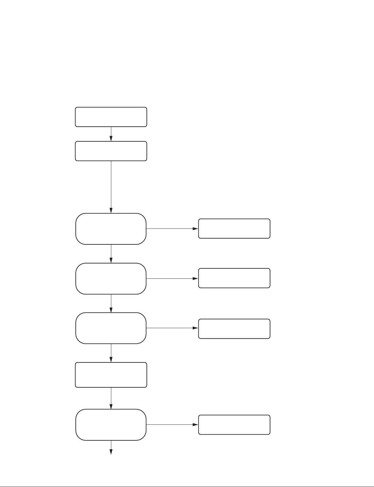
1-1-1. Flow Chart before Service
Before providing services, check symptoms according to the flow chart below.
Start
Serial number of this unit
Information of connection equipment (Modality name, application, etc.)
Check the information from a user.
Occurrence date and its status
Frequency of occurrence (Did defects occur for the first time, irregularly
several times, or in a specific case?)
Which operation did you perform after occurrence of defects?
$
The items above are used as an information source for analyzing defects.
Therefore, collect detailed information as far as possible.
Is the cause of defects streaks
(white or black) or scratches in
a print direction or a failure or
trouble?
Failure or trouble
Does this unit normally start with
the power turned on?
Yes
Is USB connection recognized?
Yes
Acquire the information of this unit
using utility software. (Refer to step
of “1. Information tab” in
3
Section 1-6-3.)
Stripes or flaws
No
No
$
Communication with this unit cannot be performed using utility software
when menu “DIGITAL” - “DRIVER” is set to “DRV: 897” .
In this case, start this unit in a service mode (refer to Section 1-8) and
use utility software.
Check the symptoms, clean the
thermal head or replace it.
&
Cleaning: Refer to Section 1-11-2.
Replacement: Refer to Section 3-7.
Refer to “2-2-1. Power does not
turn on even though the power
switch is turned on” .
Refer to “2-2-3. Printing cannot be
performed normally from PC or no
image is output” .
UP-D898MD/X898MD
Could the defects be determined
from user information and error
history? (Refer to steps 1 and
of “1. Information tab” in
2
Section 1-6-3.)
No
Go to next page
Yes
Check the determined point or
replace the relevant parts.
1-1 (E)
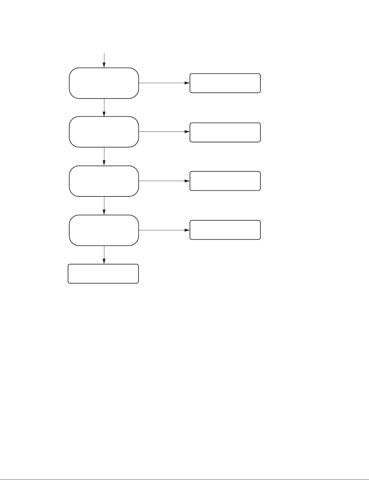
From the previous page
Can a defective point be
determined by self-diagnosis?
(Refer to Section 3-13.)
No
Can a 17-step test pattern be
normally printed?
(Refer to Section 3-1-3.)
No
Cannot paper be printed at all or
is paper printed in white?
No
Is the image in a test pattern
disturbed?
No
Yes
Yes
Yes
Yes
Check the determined point or
replace the relevant parts.
(Refer to Section 2-1.)
Normal
Refer to “2-2-3. Printing cannot be
performed normally from PC or no
image is output” .
Refer to “2-2-5. Print image is
distorted in the paper feed direction
(irregular feeding)” .
Check the contents of a trouble.
1-2 (E)
UP-D898MD/X898MD
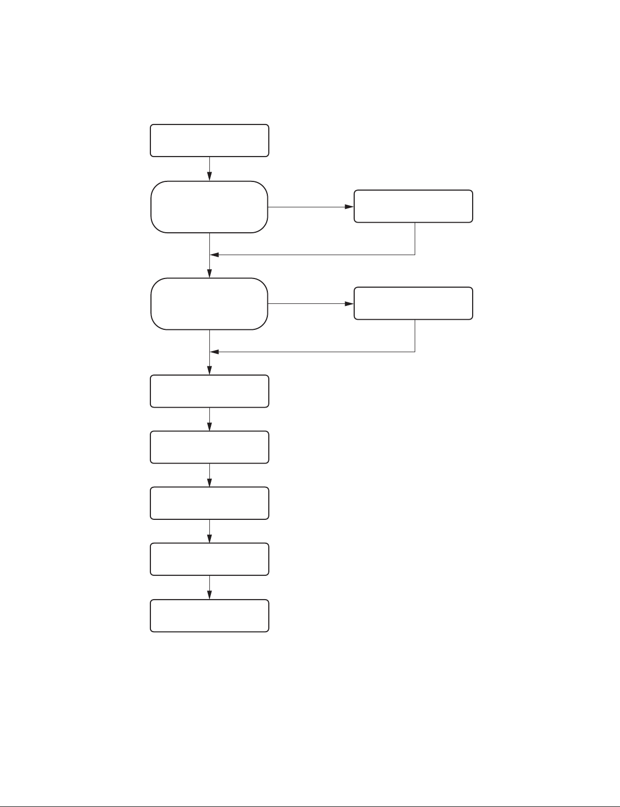
1-1-2. Flow Chart after Service
After terminating services, check symptoms according to the flow chart below.
Start
Was this unit disassembled?
No
Is upgrading of firmware required?
No
Install a UPP-110HG.
Print a 17-step test pattern.
(Refer to Section 3-1-3.)
Clean the thermal head and platen
roller. (Refer to Section 1-11.)
Yes
Yes
&
Thermal head: Refer to Section 1-11-2.
Platen roller: Refer to Section 1-11-3.
Perform self-diagnosis and check
that no problem exists in
assembling. (Refer to Section 3-13.)
Upgrade the firmware.
(Refer to Section 1-7.)
UP-D898MD/X898MD
Check the external view and
clean it. (Refer to Section 1-11-1.)
Return this unit to a user.
$
Check that paper and USB flash memory are removed.
1-3 (E)
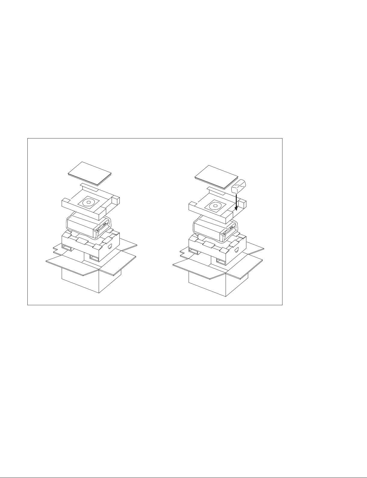
1-2. Precaution for Transporting
Perform the operation below so as to prevent the damage due to vibration and shock when transporting
this unit.
. Remove the printer paper and transport with closing the door.
. When you lift up the printer, do not hold the opened door. Otherwise, it may cause a failure due to an
excessive force applied to the door mechanism. Also, your hand might accidentally get caught between
the door and main unit resulting in injury.
. Use the packaging materials supplied for this unit.
n
Keep the packing materials removed during the delivery and installation. Do not discard them.
UP-D898MD UP-X898MD
1-4 (E)
UP-D898MD/X898MD

1-3. Board Location and Main Parts Location
1-3-1. Board Location
KY-711 board
SE-1143 board
SU-167 board
MA-195 board
SE-1142 board
1-3-2. Main Parts Location
DC motor
Stepping motor
Thermal head
Switching regulator
UP-D898MD/X898MD
1-5 (E)
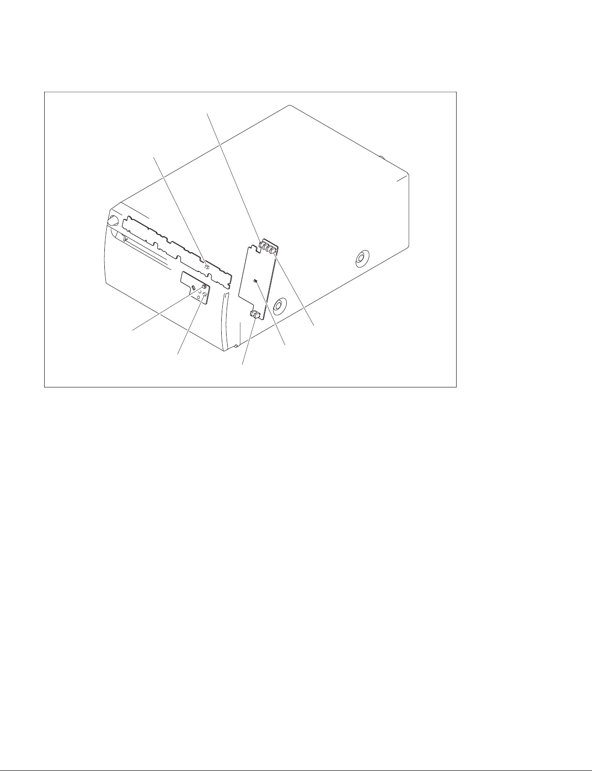
1-3-3. Sensor Location
Head position sensor (Print)
Edge sensor
(Light receiving side)
Edge sensor
(Light emitting side)
Tray sensor
(Light receiving side)
Door sensor
Head position sensor
(Home)
Tray sensor
(Light emitting side)
1-4. Tightening torque
Tighten the following screws to the tightening torques as described below.
n
The screw (BVTT2.6 x 5) of this unit has two types of the tighten torque. Be careful not to confuse.
. B3 x 6: 0.80 ?0.05 N.m
. BVTT2.6 x 4: 0.80 ?0.05 N.m
. BVTT2.6 x 5 (for excluding paper holder): 0.80 ?0.05 N.m
. BVTT2.6 x 5 (for paper holder): 0.50 ?0.05 N.m
. P3 x 4: 0.50 ?0.05 N.m
. PS3 x 4: 0.80 ?0.05 N.m
. PS3 x 6: 0.80 ?0.05 N.m
. PS4 x 8: 1.40 ?0.15 N.m
. PSW3 x 8: 0.80 ?0.05 N.m
. LOCK ACE screw (M2): 0.20 ?0.05 N.m
. Tapping screw M1.7: 0.13 ?0.02 N.m
. N6, TYPE2: 1.20 ?0.10 N.m
When using the torque driver with the unit representation of cN.m, calculate the value as follows.
Example: 0.8 N.m = 80 cN.m
1-6 (E)
UP-D898MD/X898MD
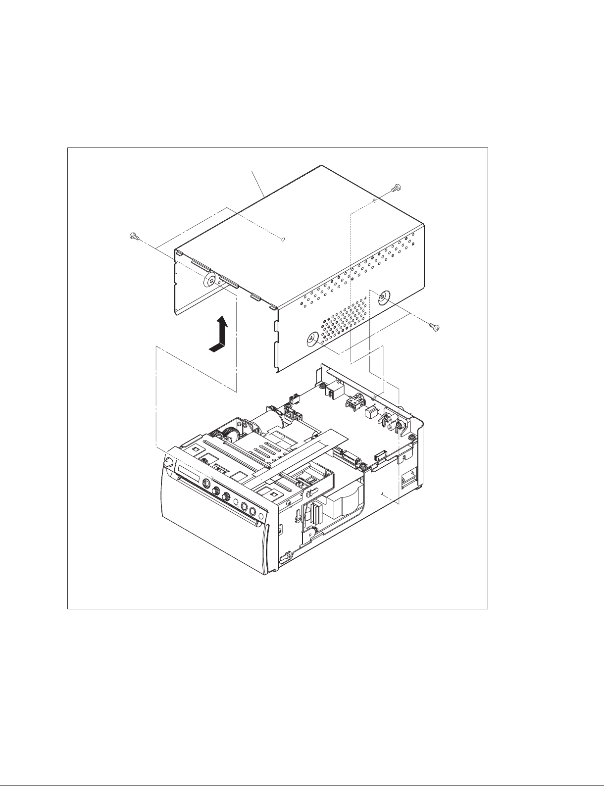
1-5. Removing/Installing the Cabinet
1-5-1. Top Cover
1. Remove the five screws, then remove the top cover in the direction of the arrow.
Top cover
B3 ) 6
) 6
B3
B3
) 6
The illustration indicates UP-X898MD.
2. To install, reverse the removal procedure.
UP-D898MD/X898MD
1-7 (E)
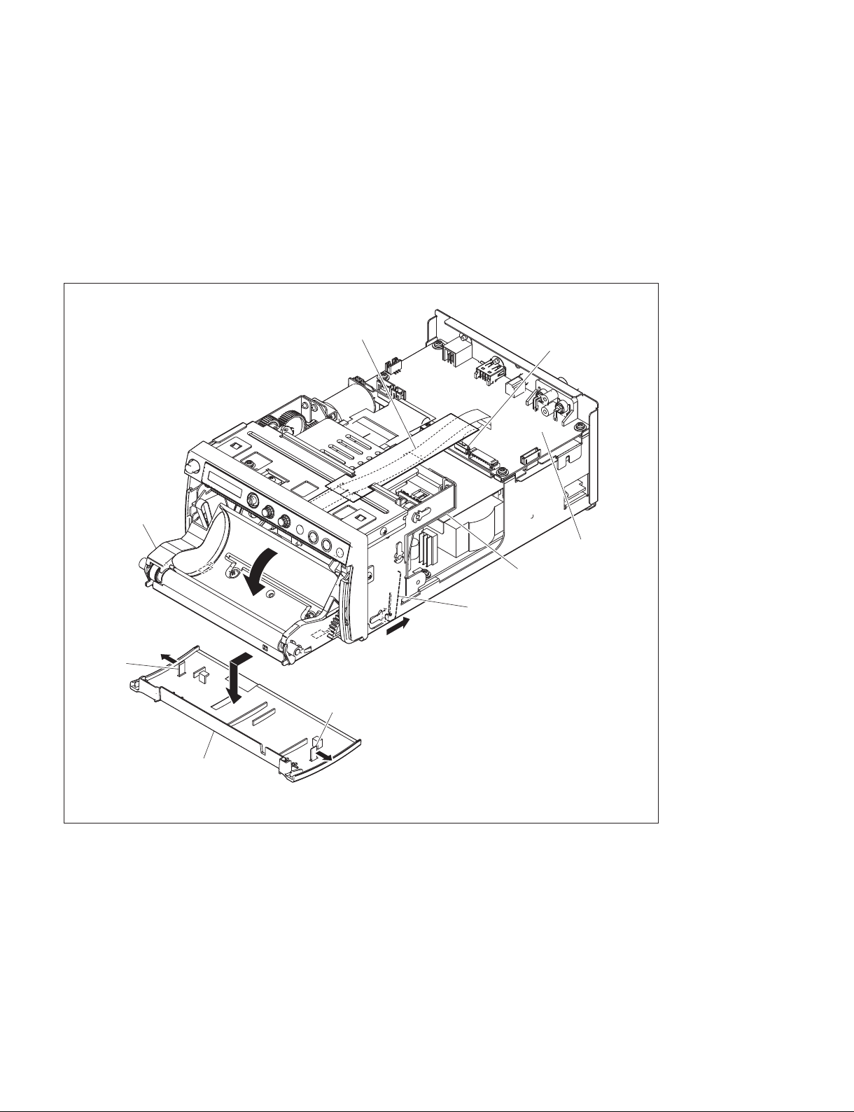
1-5-2. Front Panel Block Assembly
1. Remove the top cover. (Refer to Section 1-5-1.)
2. Release the lock arm on the mechanical deck portion (bottom) in the direction of the arrow A, then
open the door block assembly in the direction of the arrow B.
3. Remove the two hooks in the right and left directions of the arrows C, then remove the door panel in
the direction of the arrow D.
4. Disconnect the flexible flat cable from the connector (CN1103) on the MA-195 board.
Door block assembly
C
Hook
B
D
Flexible flat cable
CN1103
MA-195 board
Mechanical deck portion
Lock arm
A
Hook
1-8 (E)
Door panel
C
The illustration indicates UP-X898MD.
UP-D898MD/X898MD
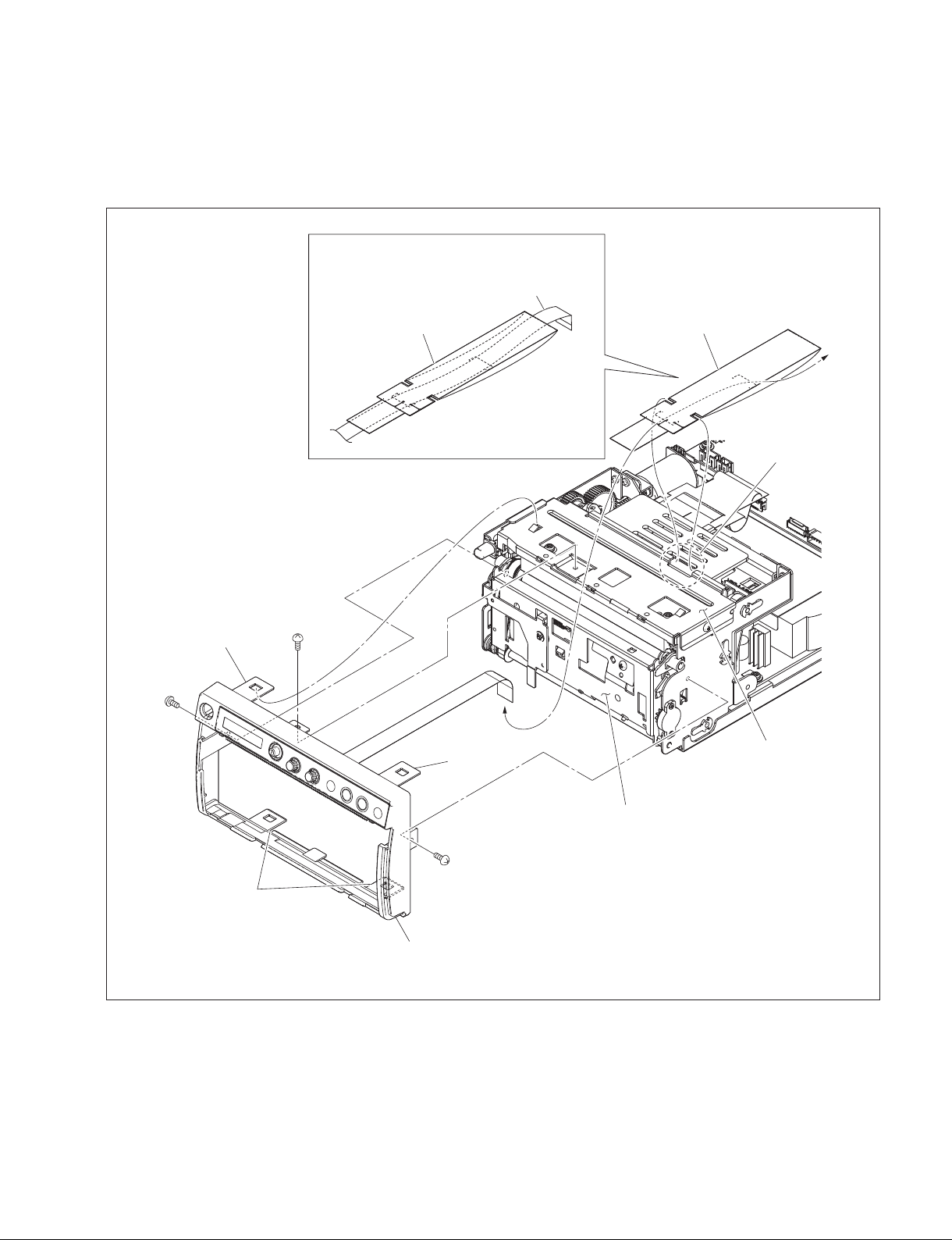
5. Close the door block assembly.
6. Remove the FFC guard (KY) from the portion A of the MD top chassis.
7. Remove the three screws and four hooks, then remove the front panel block assembly.
8. Remove the FFC guard (KY) from the flexible flat cable.
When attaching the flexible flat cable, route it
through the FFC guard (KY).
Flexible flat cable
BVTT
2.6 ) 4
Hook
BVTT
2.6
FFC guard (KY)
)
4
Hook
FFC guard (KY)
Portion A
MD top chassis
Hooks
9. To install, reverse the removal procedure.
UP-D898MD/X898MD
BVTT
2.6
)
4
Front panel block assembly
Door block assembly
The illustration indicates UP-X898MD.
1-9 (E)
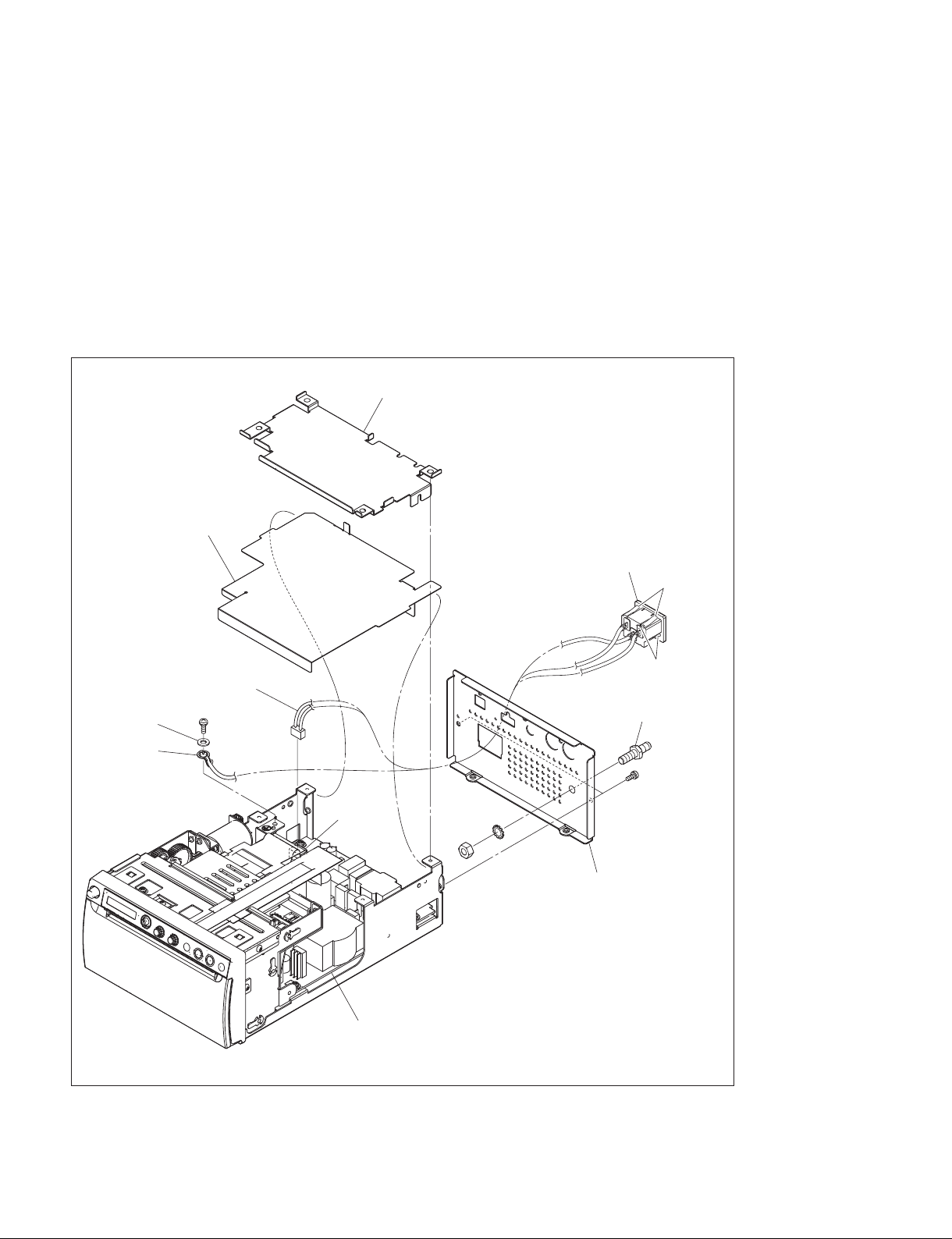
1-5-3. Rear Panel
1. Remove the top cover. (Refer to Section 1-5-1.)
2. Remove the MA-195 board. (Refer to Section 3-1.)
3. Remove the shield plate (MA) and insulating sheet (MA).
4. Remove the screw (PS4 x 8), then remove the washer (W4) and earth terminal.
5. Disconnect the harness from the connector (CN101) on the switching regulator.
6. Remove the two screws (P3 x 4), then remove the rear panel.
7. Remove the four hooks, then remove the AC inlet.
8. Remove the nut (N6) and washer (LW6), then remove the equipotential terminal.
Shield plate (MA)
Insulating sheet (MA)
AC inlet
Hooks
Harness
PS4 ) 8
W4
Earth terminal
CN101
Switching regulator
9. To install, reverse the removal procedure.
N6
Equipotential terminal
P3
LW6
Rear panel
The illustration indicates UP-X898MD.
Hooks
) 4
1-10 (E)
UP-D898MD/X898MD

1-6. General Information of Utility Software
1-6-1. Required Equipment/Tools
. Personal computer (PC) having the USB interface
. OS: Windows Vista/7/8
. Utility software: Utility Tool for UP-DX898MD.exe
t
For obtaining the utility software, contact your local Sony Sales Office/Service Center.
. USB cable
n
Use the USB 2.0 certified USB cable having a length of 2 m or less. Use of cables other than specified
may cause unstable operation of this unit.
. Thermal Print Media: UPP-110HG (Part number: 1-772-473-13)
1-6-2. Preparation
1. Connect this unit and PC using the USB cable.
t
The installation of printer driver may be requested when this unit and PC are connected. However, it
is not required to install the printer driver when using this utility software.
2. Turn on the power of PC.
3. Press the power switch of this unit to turn on the power.
4. Start the utility software (Utility Tool for UP-DX898MD.exe).
UP-D898MD/X898MD
1-11 (E)
1-6-3. Function Description
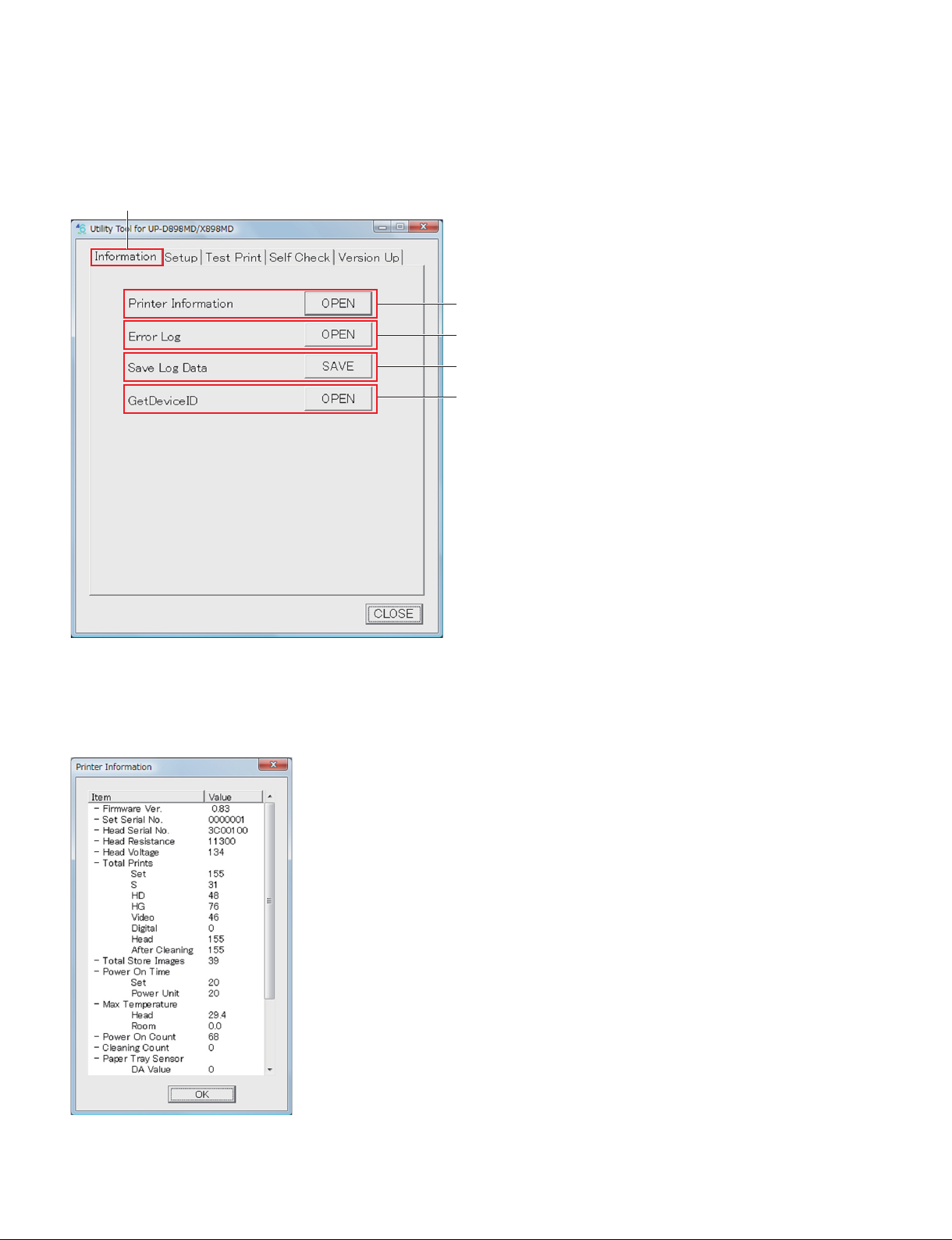
1. Information tab
Information tab
1
2
3
4
1 Printer Information
When you click the [OPEN] button, the information of this unit is obtained from EEPROM (IC507/
MA-195 board) of this unit and displayed.
1-12 (E)
UP-D898MD/X898MD

. Firmware Ver.: Version of firmware
. Set Serial No.: Serial number of this unit
. Head Serial No.: Serial number of thermal head
. Head Resistance: Resistance value (Z) of thermal head
. Head Voltage: Voltage setting value (D/A value) of thermal head
. Total Prints:
Set: Total print count of this unit
S: Total print count of paper (UPP-110SE)
HD: Total print count of paper (UPP-110HD)
HG: Total print count of paper (UPT-110HG)
Video: Total print count of image captured from video signal
Digital: Total print count of digital image transmitted from PC
Head: Total print count of thermal head
After Cleaning: Total print count after cleaning of thermal head
. Total Store Images: Number of image stored in USB flash memory
. Power On Time
Set: Total power on time of this unit (h)
Power Unit: Total power of time of power unit (h)
. Max Temperature
Head: Maximum temperature of thermal head (dC)
Room: Maximum room temperature (dC)
. Power ON Count: Number of power ON times
. Cleaning Count: Number of thermal head cleaning times
. Paper Tray Sensor: Information of paper tray sensor (Luminance side: D201/SE-1143 board, light
receiving side: Q301/SE-1142 board)
DA Value: Amount of luminescence (D/A value)
High Level: Light receiving portion High level
Low Level: Light receiving portion Low level
Threshold: Light receiving portion threshold level
. Paper Front Sensor: Information of paper tray sensor (Luminance side: D301/SE-1142 board, light
receiving side: Q201/KY-711 board)
DA Value: Amount of luminescence (D/A value)
High Level: Light receiving portion High level
Low Level: Light receiving portion Low level
Threshold: Light receiving portion threshold level
. [OK] button: Closes the Printer Information screen.
UP-D898MD/X898MD
1-13 (E)
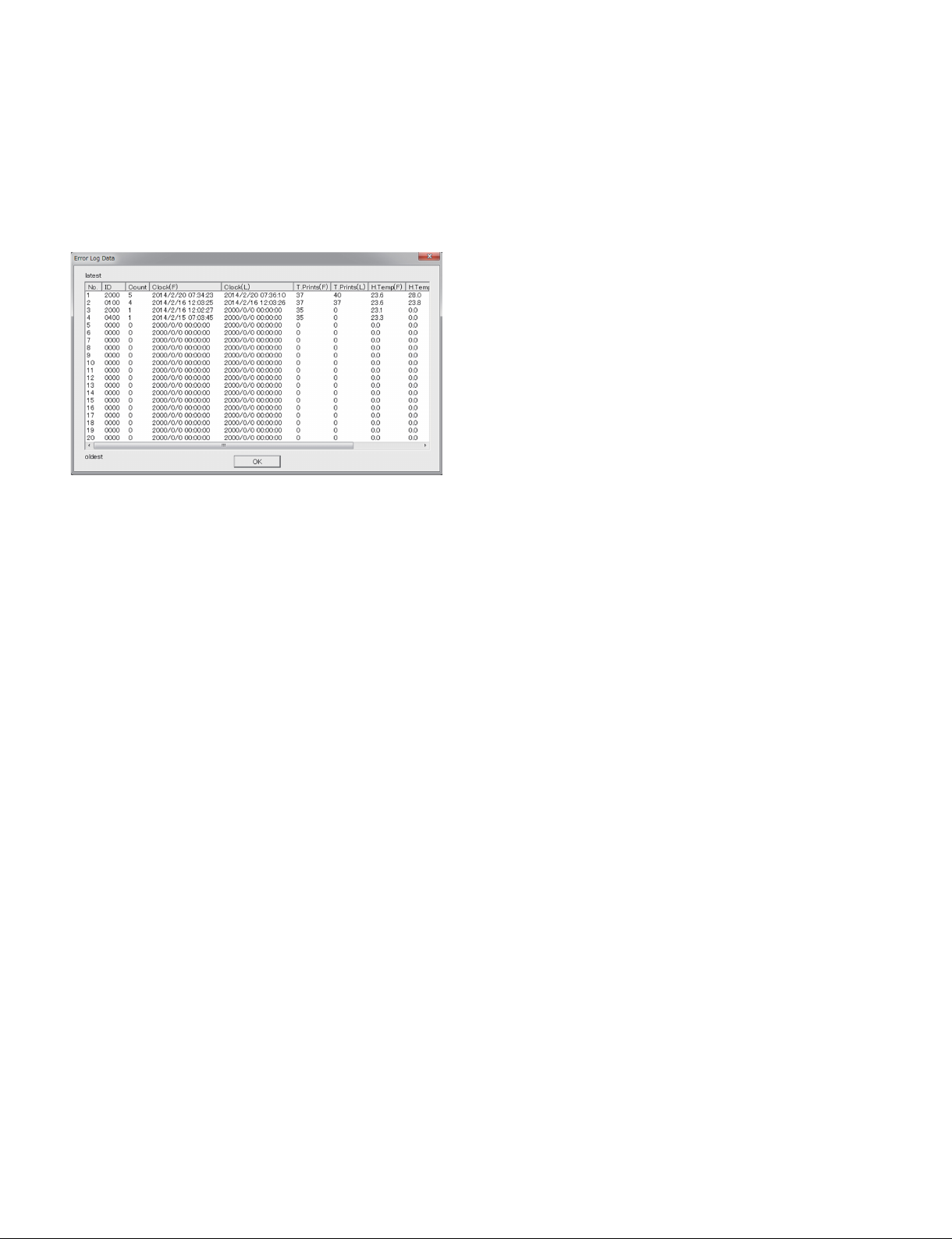
2 Error Log
When you click the [OPEN] button, the 20 errors that have occurred in the past are displayed. When the
number of error exceeds 20, the error is overwritten by the latest error beginning with the chronologically
oldest error (No. 20). However, when the same errors are overlapped (the errors of the same error code
occurred continuously), only the Count number of the latest error (No. 1) is overwritten (increased) and
the error No. 20 is not deleted.
t
For the error code ID, refer to Section 2-1.
. ID: Error code ID information
. Count: Number of overlapping errors
. Clock (F): Date and time when the first error is detected
. Clock (L): Date and time when the last error is detected (This is displayed only when the errors are
overlapped.)
. T.Prints (F): Total print count of this unit when the first error is detected
. T.Prints (L): Total print count of this unit when the last error is detected (This is displayed only when
the errors are overlapped.)
. H.Temp (F): Thermal head temperature (dC) when the first error is detected
. H.Temp (L): Thermal head temperature (dC) when the last error is detected (This is displayed only
when the errors are overlapped.)
. R.Temp (F): Room temperature (dC) when the first error is detected
. R.Temp (L): Room temperature (dC) when the last error is detected (This is displayed only when the
errors are overlapped.)
. [OK] button: Closes the Error Log screen.
3 Save Log Data
When you click the [Save] button, the menu setting and operation log information of this unit as well as
the information displayed in Printer Information and Error Log are saved as CSV format file on PC.
The saved file can be displayed by using the spreadsheet software such as Excel.
The information in this file is important when the person in charge of design performs a failure analysis.
4 GetDeviceID
Not used
1-14 (E)
UP-D898MD/X898MD
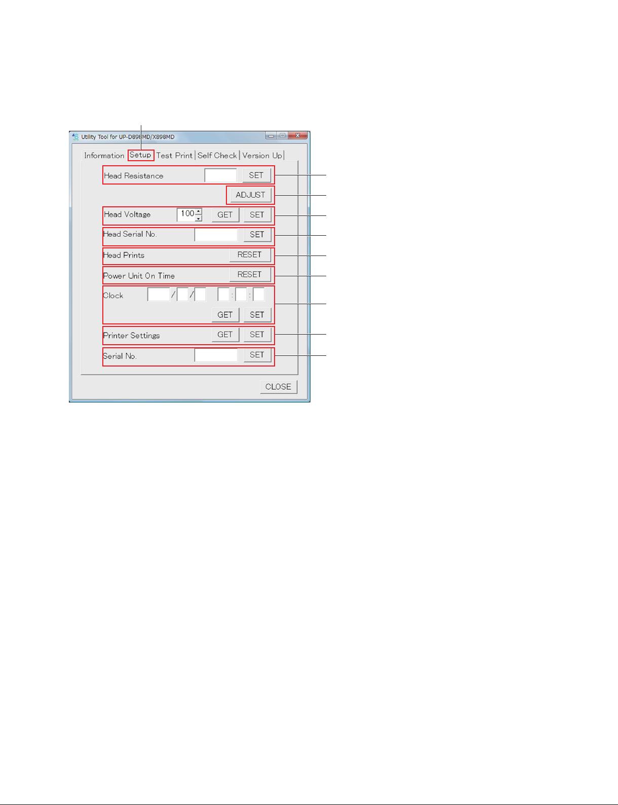
2. Setup tab
Setup tab
1
2
3
4
5
6
7
8
9
1 Head Resistance
Sets the thermal head resistance value.
When you click the [SET] button, the value in the edit box is written in EEPROM (IC507/MA-195
board) of this unit.
2 [ADJUST] button
Calculates the head voltage setting value based on the thermal head resistance value, and write the value
(D/A value) in EEPROM (IC507/MA-195 board) of this unit.
3 Head Voltage
Obtains and sets the thermal head voltage setting value (D/A value).
. [GET] button: When you click this button, the information stored in EEPROM (IC507/MA-195 board)
of this unit is displayed in the edit box.
. [SET] button: When you click this button, the value in the edit box is written in EEPROM (IC507/
MA-195 board) of this unit.
4 Head Serial No.
Sets the thermal head serial number.
When you click the [SET] button, the number in the edit box is written in EEPROM (IC507/MA-195
board) of this unit.
5 Head Prints
When you click the [RESET] button, the total print count of thermal head is reset.
UP-D898MD/X898MD
1-15 (E)

6 Power Unit On Time
When you click the [RESET] button, the total on time of power unit is reset.
7 Clock
Obtains and sets the date/time information.
. [GET] button: When you click this button, the date/time information obtained from this unit is dis-
played in the edit box.
. [SET] button: When you click this button, the date/time information in the edit box is set in this unit.
8 Printer Settings
Obtains and sets the menu setting information of this unit.
. [GET] button: When you click this button, the menu setting information stored in EEPROM (IC507/
MA-195 board) of this unit is saved as binary file (.CNS) on PC.
. [SET] button: When you click this button, the menu setting information of the specified binary file
(.CNS) is written in EEPROM (IC507/MA-195 board) of this unit.
9 Serial No.
Sets the serial number of this unit.
When you click the [SET] button, the number in the edit box is written in EEPROM (IC507/MA-195
board) of this unit.
1-16 (E)
UP-D898MD/X898MD
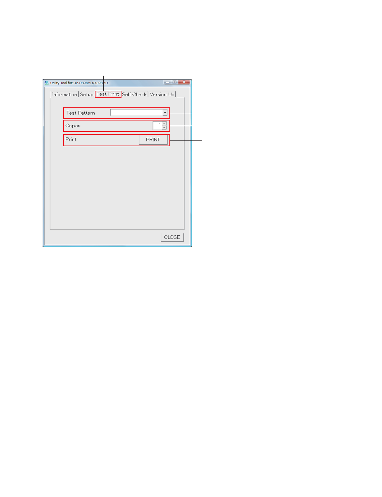
3. Test Print tab
Test Print tab
1
2
3
1 Test Pattern
Selects the image pattern to be printed.
. STEP: Built-in stair-step pattern
. CROSS STEP: Built-in cross step pattern
. LAMP: Built-in lamp image
. CROSS LAMP: Built-in cross lamp image
. SKEW LAMP: Built-in skew lamp image
. HEAD CONFIRM PAT1: Built-in thermal head confirmation pattern 1
. HEAD CONFIRM PAT2: Built-in thermal head confirmation pattern 2
. LOG: Log information in this unit
. BLACK (S/L)
. DARK GRAY (S/L)
. GRAY (S/L)
. LIGHT GRAY (S/L)
. WHITE (S/L)
*
: Built-in 100% black pattern
*
*
: Built-in gray pattern
: Built-in gray pattern (darker)
*
*
: Built-in gray pattern (lighter)
: Built-in 100% white pattern
*: Print size: Horizontal x Vertical [mm]
S: 100 x 75
L: 100 x 117
UP-D898MD/X898MD
1-17 (E)
2 Copies
Sets the number of copies.
You can set the number of copies from 1 to 255 sheets.
3 Print
When you click the [PRINT] button, the test print is performed.
The pattern selected in 1 is printed by the number of copies set in 2.
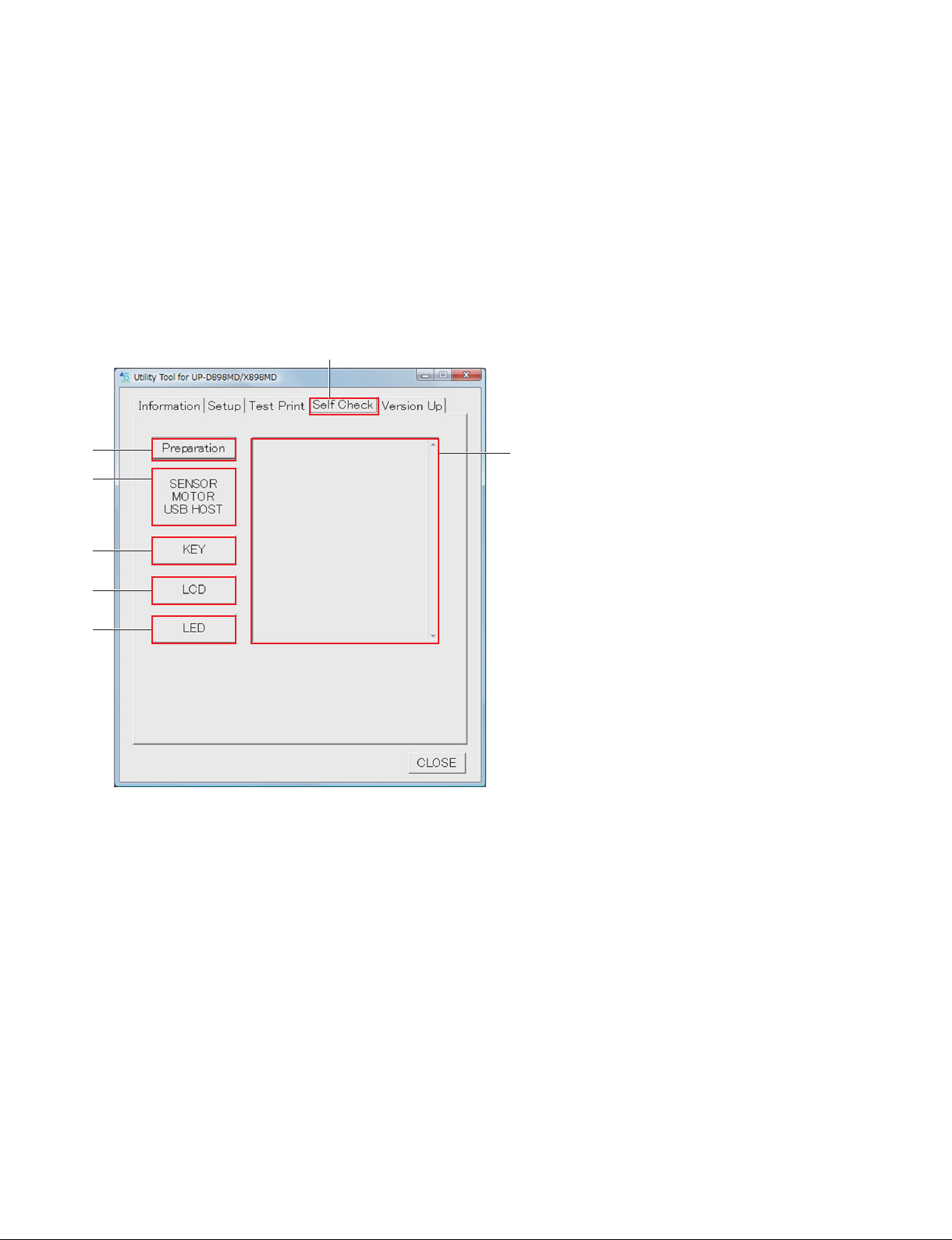
4. Self Check tab
Self Check tab
1
2
3
4
5
6
1 [Preparation] button
Performs the preparation of self check.
When this button is clicked, “Before checking… Eject the paper. Close the door. Insert USB Flash Drive.
(UP-X898MD)” is displayed in the edit box 7.
According to the display, eject the paper, close the door and connect the USB flash memory (UP-X898MD
only).
2 [SENSOR|MOTOR|USB|HOST] button
Performs the self check of SDRAM, EEPROM, sensors, and DC motor and thermistor of thermal head in
this unit.
After the check is completed, if there is no defective portion, “Check Result No Error, Check OK!” is
displayed in the edit box 7.
If any defective portion is detected, it is displayed.
t
For the cause and remedy of the defective portion, refer to Section 2-1.
1-18 (E)
UP-D898MD/X898MD

3 [KEY] button
When this button is clicked, the Check Key screen is opened. The conduction check of button, knob and
menu lever of this unit is performed.
Operate the front operation device displayed on LCD of this unit, then click the [OK] button of the Check
Key screen.
After the check is completed, the check result is displayed in the edit box 6.
4 [LCD] button
When this button is clicked, the Check LCD screen is opened, and all LCDs of this unit light up. Visually
check that all LCDs of this unit are lit.
After the check is completed, click the [OK] button of the Check LCD screen.
5 [LED] button
When this button is clicked, the Check LED screen is opened, and all LEDs of this unit light up.
. Button LED: Blinks in white.
. LCD backlight LED: Blinks in green and amber alternately.
. USB access LED (UP-X898MD only): Blinks in green and amber alternately.
Visually check that all LEDs of this unit blink.
After the check is completed, click the [OK] button of the Check LED screen.
6 Edit box
Displays the check result and message.
UP-D898MD/X898MD
1-19 (E)
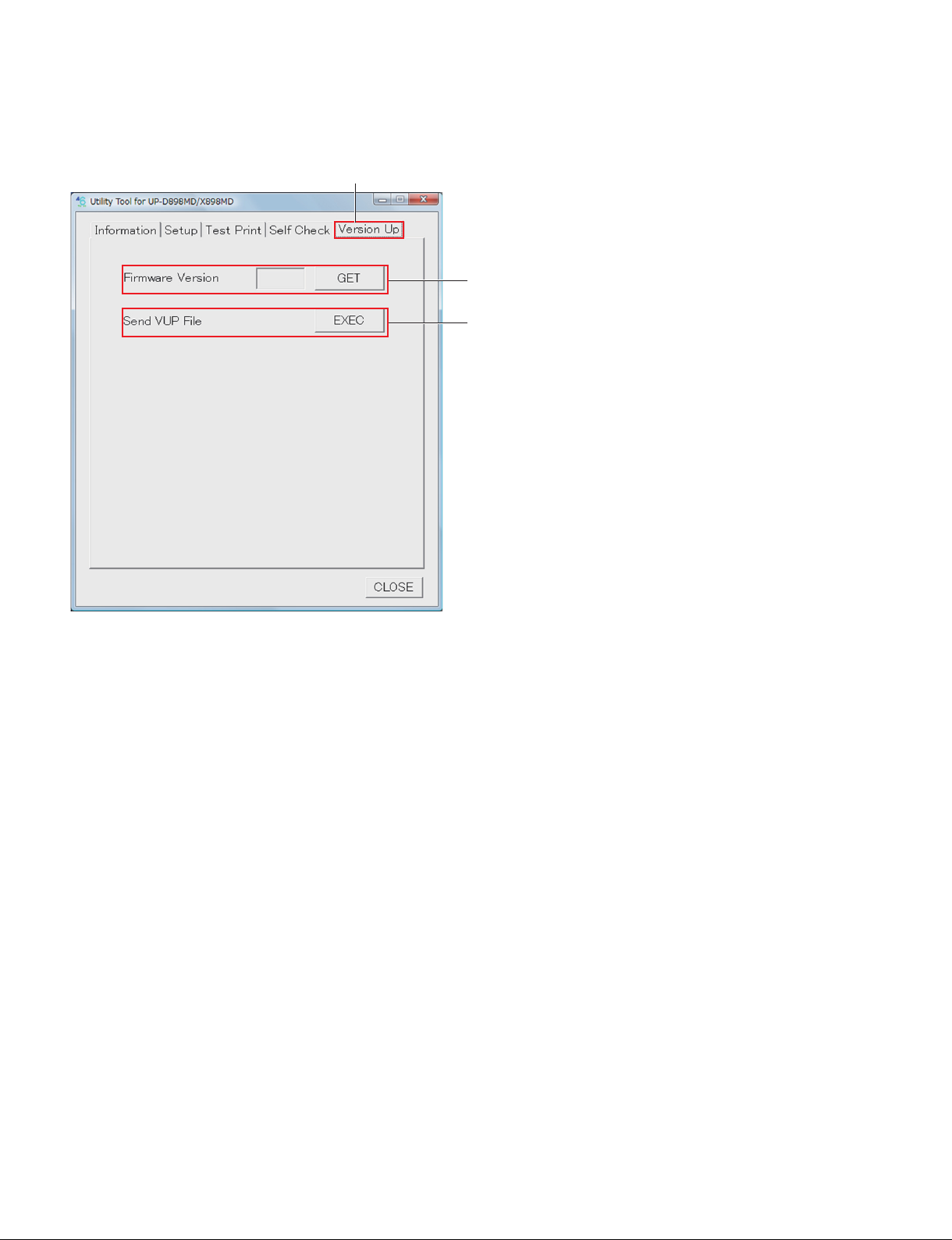
5. Version Up tab
Version Up tab
1
2
1 Firmware Version
Displays the firmware version of this unit.
When the [GET] button is clicked, the firmware version is displayed in the edit box.
2 Send VUP File
Performs the firmware version upgrade.
When the [EXEC] button is clicked, the specified version upgrade file is sent to this unit.
n
If the power is turned off in the course of the firmware writing, this unit will not start. Never turn off the
power of this unit before completing the writing. If the power is accidentally turned off and this unit will
not start, replace the MA-195 board. (Refer to Section 3-1.)
t
For the firmware version upgrade procedure, refer to Section 1-7.
1-20 (E)
UP-D898MD/X898MD
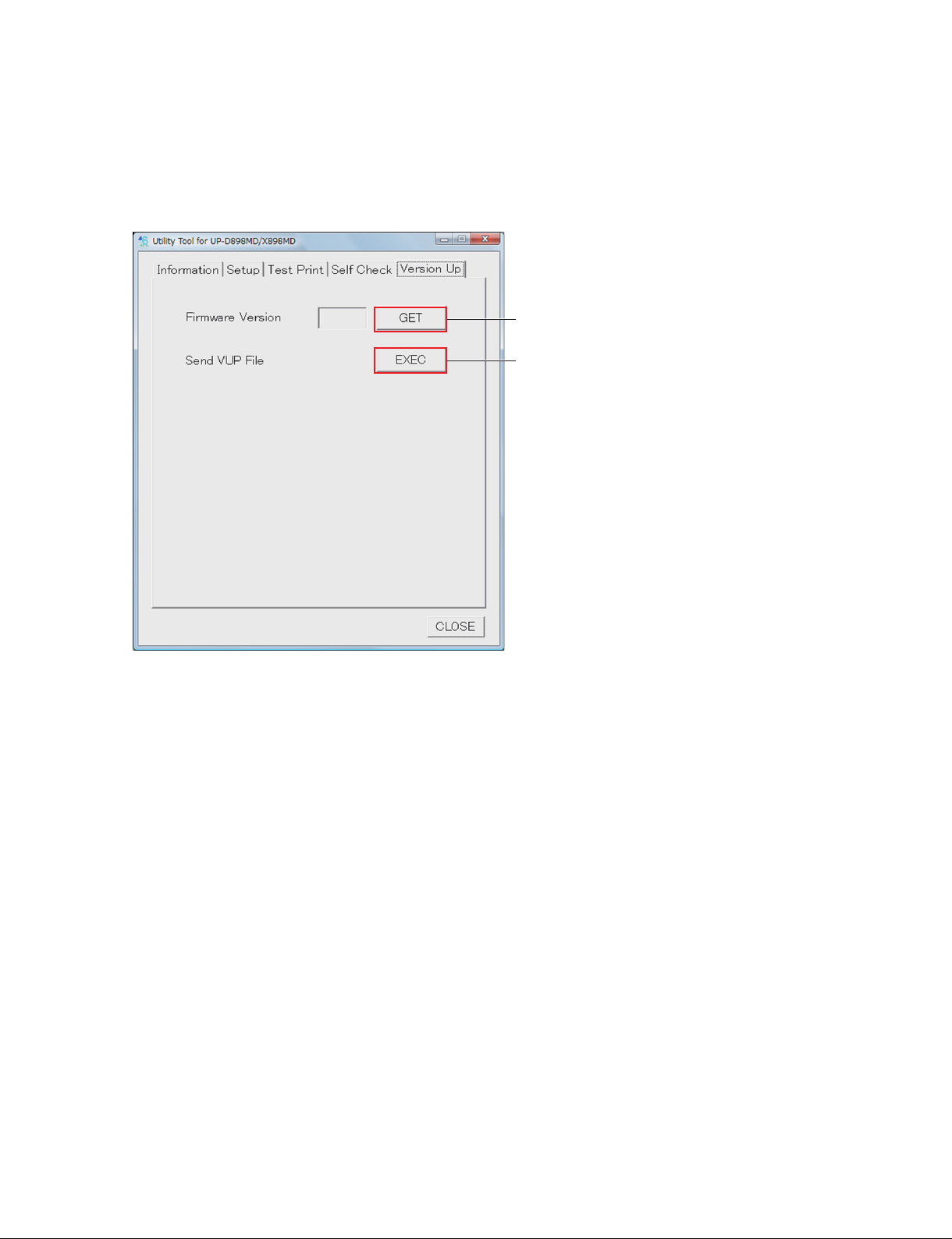
1-7. Firmware Version Upgrade
1. Start the utility software. (Refer to Section 1-6.)
2. Click the [GET] button of “Firmware Version” of the Version Up tab.
The version of the firmware currently installed in this unit is displayed.
[GET] button
[EXEC] button
3. Write down the current firmware version.
4. Click the [EXEC] button of “Send VUP File”.
5. Select the firmware (vup) file, and then click the [OPEN] button.
After the file is transferred, the firmware writing is started.
The display of LCD during the firmware writing is as follows.
. UPGRADE (blinks): Information is being written in FLASH.
. REBOOT (lights up): Writing is completed.
When the firmware writing is completed, 3 beep sounds are made.
n
If the power is turned off in the course of the firmware writing, this unit will not start. Never turn off
the power of this unit before completing the writing. If this unit will not start, replace the MA-195
board. (Refer to Section 3-1.)
6. Check that the writing is completed, and then restart this unit.
7. Click the [GET] button of “Firmware Version” of Version Up tab.
8. Check that the firmware is upgraded to the latest version.
UP-D898MD/X898MD
1-21 (E)

1-8. Service Mode
It is possible to perform the printing of built-in pattern and the various settings with this unit alone. This
mode is used when you cannot use the utility software due to the USB device failure and so forth.
1-8-1. Startup Procedure
1. Turn on the power while pressing and holding the [FEED] button and [COPY] button simultaneously.
2. After approx. 4 seconds, check that the LCD backlight of this unit blinks in green and amber alternately, and then release each button.
The service mode is started.
1-8-2. Service Mode Menu
When this unit is started in the service mode, the first item of menu is changed from “HISTORY” (normal
mode) to “SERVICE”.
The menu structure of service mode is as follows.
When this unit is started in the service mode, even if you do not operate the button for approx. 20 seconds,
the unit does not exit from the menu mode because the time out function does not work.
READY
SERVICE
PATERN Test pattern print
SV.QTY Number of test pattern print
STR.MEM USB flash memory saving function ON/OFF
HEAD.V Thermal head voltage setting
LPF Low pass filter
PRT.LOG Log print
INIT Initialization of setting
MECHA Mechanical operation of individual motors
TEMP Temperature display
TMODE Switching of Toshiba mode
RMCAP Remote capture timing
PRT.HELP
ADJUST
VIDEO
DIGITAL
PRT.MENU
PREF.
CLEAN.TH
CONFIG.
SERIAL.N
1-22 (E)
UP-D898MD/X898MD
 Loading...