

Page 1

2-891-198-01(1)
Digital Photo Printer
Operating Instructions
UP-GR700
© 2007 Sony Corporation
Page 2

Owner's Record
The model and serial numbers are located at the rear.
Record these number in the space provided below.
Refer to these numbers whenever you call upon your
Sony dealer regarding this product.
Model No. ____________________
Serial No. ____________________
WARNING
To reduce the risk of fire or electric shock, do
not expose this apparatus to rain or moisture.
To avoid electrical shock, do not open the
cabinet. Refer servicing to qualified personnel
only.
THIS APPARATUS MUST BE EARTHED.
To disconnect the main power, unplug the AC
IN connector.
Warning on power connection
1. Use the approved Power Cord (3-core mains lead) /
Appliance Connector / Plug with earthing-contacts
that conforms to the safety regulations of each
country if applicable.
2. Use the Power Cord (3-core mains lead) / Appliance
Connector / Plug conforming to the proper ratings
(Voltage, Ampere).
If you have questions on the use of the above Power
Cord / Appliance Connector / Plug, please consult a
qualified service personnel.
For the customers in the U.S.A.
This equipment has been tested and found to comply
with the limits for a Class A digital device, pursuant to
Part 15 of the FCC Rules. These limits are designed to
provide reasonable protection against harmful
interference when the equipment is operated in a
commercial environment. This equipment generates,
uses, and can radiate radio frequency energy and, if not
installed and used in accordance with the instruction
manual, may cause harmful interference to radio
communications. Operation of this equipment in a
residential area is likely to cause harmful interference in
which case the user will be required to correct the
interference at his own expense
You are cautioned that any changes or modifications not
expressly approved in this manual could void your
authority to operate this equipment.
All interface cables used to connect peripherals must be
shielded in order to comply with the limits for a digital
device pursuant to Subpart B of Part 15 of FCC Rules.
2
Page 3

Table of Contents
Introduction
Features .................................................................. 4
Basic Application Example ................................4
Location and Function of Parts and Controls ....4
Relationship Between the STATUS Indicator and
the ERROR indicator ........................................ 5
Preparation
Supplied Accessories ............................................. 7
Installing the Printer ............................................. 7
Placing the Printer .............................................. 7
Connections ............................................................ 8
Installing the Printer Driver ................................ 8
USB Port Connection ......................................... 8
Operation
Loading the Paper Roll and Ink Ribbon ............. 9
Loading the Paper Roll and Ink Ribbon ............. 9
Removing the Ink Ribbon and Paper Roll ........14
Printing from the Computer ...............................16
Printing ............................................................. 16
Miscellaneous
Precautions ........................................................... 19
Safety ................................................................ 19
Installation ........................................................ 19
On Transporting the Printer .............................. 19
Cleaning ........................................................... 20
Specifications ........................................................ 22
List of Messages ................................................... 22
Troubleshooting ................................................... 23
If the Ink Ribbon Breaks during Use ...............24
If the Paper Jams .............................................. 25
Index ..................................................................... 26
3
Page 4
Introduction
Location and Function of Parts and Controls
Introduction
Features
The UP-GR700 Digital Photo Printer is a dye
sublimation thermal transfer printer providing high
quality, high resolution (300 dpi), and high speed
printing of computer image data in full color (256
gradations and 16.7 million colors).
For more details, see the reference pages (numbers
enclosed in parentheses).
Front panel
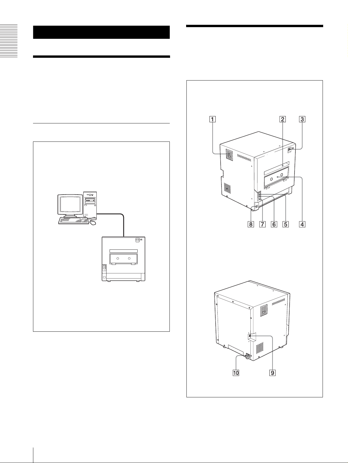
Basic Application Example
Computer: provides
image data for printing
and printer control
signals
UP-GR700 Digital Photo Printer
Rear panel
A Filter cover (21)
Provided to prevent the printer from becoming
clogged with dust.
4
Features / Location and Function of Parts and Controls
Page 5
B Paper output slot
Printed pages are output from the printer here.
C Lock lever for the front door
Used to open the front door when loading or
replacing the ink ribbon and paper roll, or cleaning.
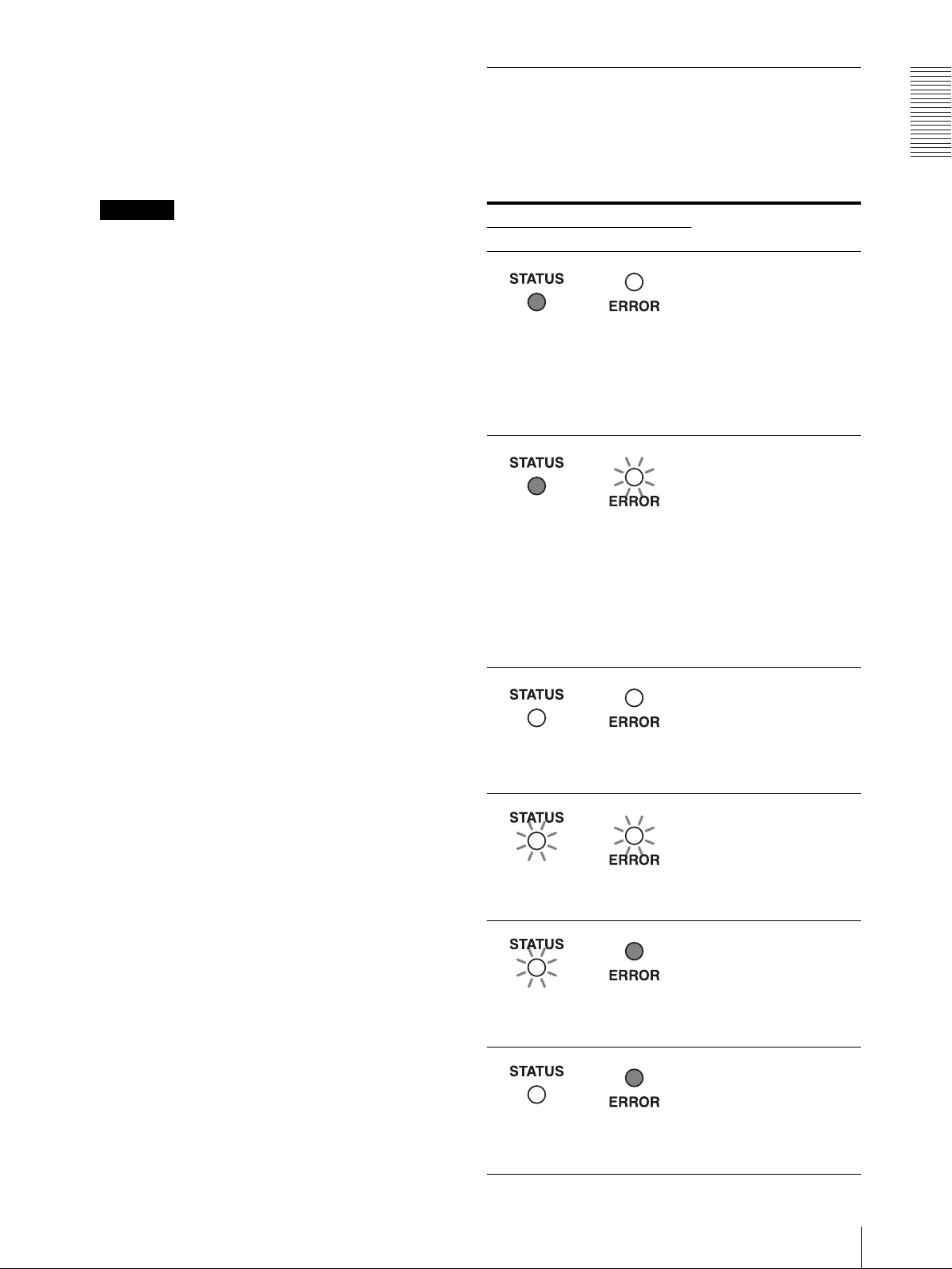
Relationship Between the STATUS Indicator and the ERROR indicator
You can confirm the status of the printer according to the
lighting status of the STATUS and ERROR indicators
located on the front panel.
Introduction
Caution
The front door is very heavy. Be careful when
opening it.
D Paper scrap tray (17)
While printing, a margin is left between printouts.
The excess portions of these margins are cut and
dropped into this paper scrap tray.
E STATUS indicator
Indicates the status of the printer.
For detailed information on how this indicator light
so, and its meaning, see “Relationship Between the
STATUS Indicator and the ERROR indicator” on
page 5.
F ERROR indicator
Indicates the error status of the printer.
For detailed information on how this indicator light
so, and its meaning, see “Relationship Between the
STATUS Indicator and the ERROR indicator” on
page 5.
G Cut button (14)
Press this button using a sharp-pointed object such
as a tip of a mechanical pencil, while the STATUS
indicator is lit in blue to feed roll paper by about 10
cm (4 inches) and chop off the fed excess paper.
H !Power switch
Press this switch to turn the printer on or off.
I - AC IN (power source) connector (8)
Use the proper power cord for your local power
supply (not supplied). Refer to “Warning on power
connection” on page 2.
Indicator status Printer status
STATUS ERROR
Recoverable errors such as
“door open,” “replace
paper,” and so on. The error
message and error number
Not lit
Not lit
Lit
(Blue)
Blinks
(White)
Lit
(Red)
Blinks
(Red)
Lit
(Red)
Blinks
(Red)
are displayed on the
monitor of the computer
connected to the printer.
Solve the problem,
referring to “Recoverable
error numbers and error
messages” on page 23.
Errors requiring you to turn
the printer off and on. Turn
the printer off once, and
then on again. The error
message and error number
are displayed on the
monitor of the computer
connected to the printer.
Solve the problem,
referring to “Error numbers
and error messages
requiring the printer to be
turned off and on” on page
22.
Means “Paper loading is
completed” when loading
or replacing the paper roll
and the ink ribbon.
Means paper roll or the ink
ribbon has been used up.
Load a new paper roll and
ink ribbon.
J USB connector (8)
Connects to a computer equipped with a USB
interface (USB 2.0), using a USB cable (not
supplied).
Blinks
(White)
Lit
(White)
Means image data is being
transferred.
Not lit
Means the printer is
printing.
Not lit
Location and Function of Parts and Controls
5
Page 6

Indicator status Printer status
STATUS ERROR
Means “Initializing
(Starting) Wait for a while.”
Introduction
Blinks
(Green)
Not lit
Means the print head is
cooling or the print head is
warming.
Blinks
(Blue)
Lit
(Blue)
Not lit
Print mode. The printer is
ready to print.
Not lit
6
Location and Function of Parts and Controls
Page 7
Preparation
Supplied Accessories
Make certain you have received the following
accessories.
Caution
The UP-GR700 is very heavy. The printer should be
carried by two persons. Be careful when taking the
printer out the shipping box.
Feet (2)
CD-ROM (including the operating
instructions and printer driver)
Before Using this Printer (1)
Software License Agreement (1)
Warranty Card (1)
Installing the Printer
Before setting up the unit and using it, be sure to perform
the following installation.
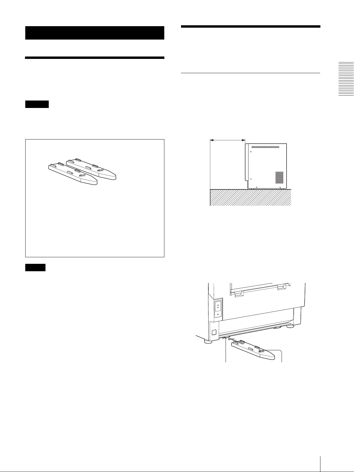
Placing the Printer
Check the location where the printer is to be installed. A
space of about 25 cm (9 7/8 inches) is required as
illustrated, so that ejected printouts will not be dropped
on the floor.
About 25 cm (9 7/8 inches)
When the printer is unstable
If the printer is unstable when you open the front door,
attach the two feet (supplied) to the printer.
Preparation
Note
The packaging materials are needed when transporting
the printer, so we suggest you keep them.
1
Insert the one foot along the rail located on one side
of the bottom of the printer.
Rail
Foot
Supplied Accessories / Installing the Printer
7
Page 8
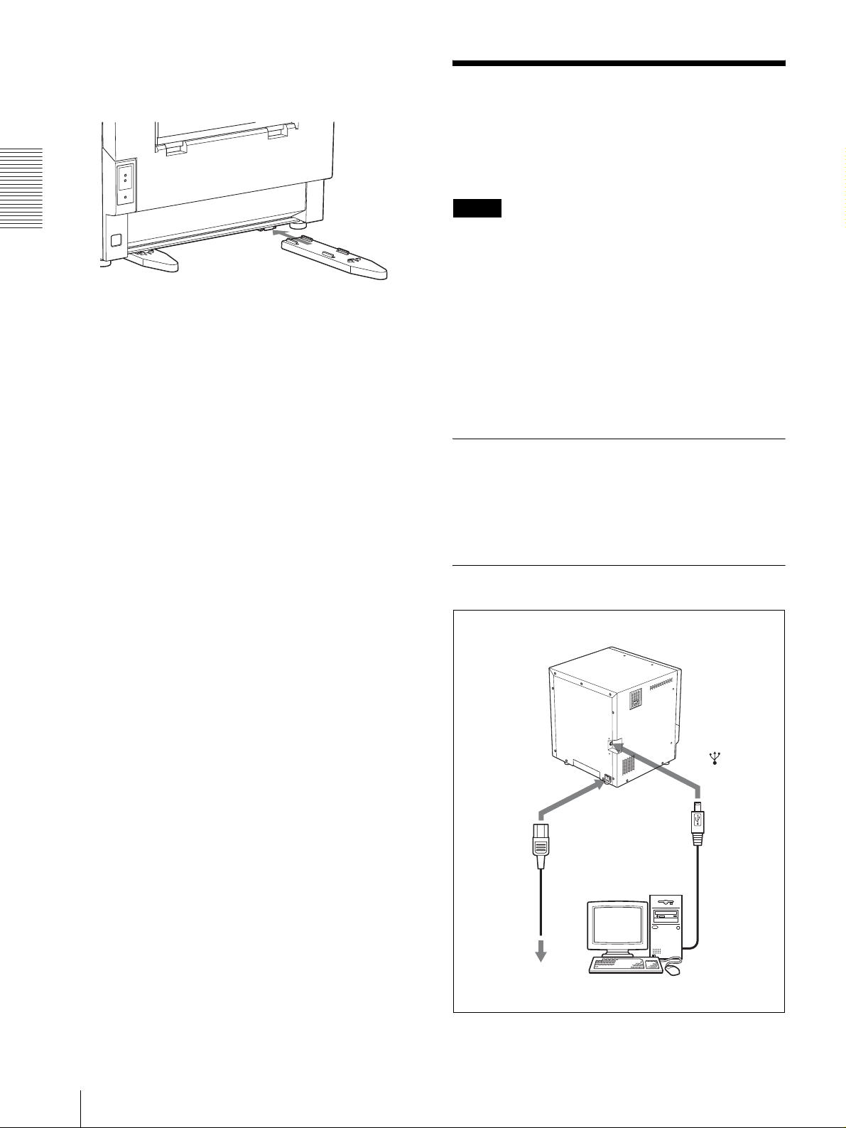
2
Insert the other foot along the rail located on the
other side of the bottom of the printer.
Connections
After connecting a USB connecting cable (not supplied)
to the printer and the computer, connect the power cord.
For details about connecting the printer, refer to the
manuals for the computer or other peripheral devices.
Notes
Preparation
• Before connecting the printer to the computer, be sure
to install the printer driver.
• Follow the connection procedures described in the
computer manual.
• Make sure that the interface cable is connected
securely at both ends.
• The printer driver software provided with the printer is
not suitable for using the printer connected to a
network.
• Operation of the printer is not guaranteed for
connection via a USB hub.
Installing the Printer Driver
Install the printer driver provided with the printer. For
detailed instructions on how to install the printer driver,
refer to the Readme.txt file and the installation manual
contained on the CD-ROM disc supplied.
USB Port Connection
UP-GR700
8
Connections
to - AC IN
connector
AC power
cord (not
supplied)
to wall outlet
to (USB)
connector
USB
connecting
cable (not
supplied)
Computer
Page 9

Operation
Loading the Paper Roll and Ink Ribbon
Recommended printing pack
The following printing pack is made especially for
the UP-GR700.
Be sure to use the ink ribbon and the paper roll in the
carton as a set.
2UPC-R710 Self-Laminating Color Printing
Pack
Ink ribbon for printing: 2
Paper roll: 2 rolls
One set of the ink ribbon and paper roll allows you to
print about 170 printouts of 203 × 254 mm size (8 × 10
inch size).
You can make printouts of either 203 × 254 or 203 × 305
mm size (8 × 10 or 8 × 12 inch size) using the 2UPCR710 Self-Laminating Color Printing Pack. 203 × 254
mm size (8 × 10 inch size) is the default setting.
You can select the desired size for your printouts using
the printer driver.
For detailed information, refer to the instructions for the
printer driver included on the CD-ROM disc supplied.
Note
When you make only 203 × 254 mm size (8 × 10 inch
size) printouts, one set of the ink ribbon and paper roll
allows you to print about 170 printouts. However, if you
make printouts of 203 × 305 mm size (8 × 12 inch size)
too, using the same roll of ink ribbon, the total number
of printouts will decrease. Also, some portion of the ink
ribbon may be left over. Do not use this left-over ink
ribbon. Replace both the paper roll and ink ribbon at the
same time.
Notes on handling the paper roll and ink
ribbon
• One set of the ink ribbon and paper roll allows you to
print about 170 printouts of 203 × 254 mm size (8 × 10
inch size). Do not replace the printing pack if it has
only been partially used. The number of printouts that
can be printed may not be guaranteed if you replace
the ink ribbon and paper before they have run out.
• We recommend that you put on gloves when handling
the paper roll.
• Stand the paper roll up vertically. If you place the
paper roll horizontally, the paper roll may roll around
and fall. This may cause an injury.
• Hold the paper roll with both hands so that you do not
drop it, because it is heavy. Dropping it may cause in
an injury.
Hold the paper roll with both hands.
Loading the Paper Roll and Ink Ribbon
When you use the printer for the first time, load the
paper roll and ink ribbon.
If the paper roll or the ink ribbon runs out while printing
is in progress, replace both paper roll and ink ribbon at
the same time. When you replace the used up paper roll
and ink ribbon with the new ones, you have to remove
the old ink ribbon and paper roll first.
For detailed information on how to remove the paper roll
and ink ribbon, see “Removing the Ink Ribbon and
Paper Roll” on page 14.
When using the printer for the first time
When you use the printer for the first time, be sure to
remove packing materials put in the printer before
loading the paper roll and ink ribbon.
Operation
Loading the Paper Roll and Ink Ribbon
9
Page 10

1
Pull the lock lever for the front door up to open the
front door.
Packing material such as the large cushion removed in
step 2 is needed when transporting the printer, so we
suggest you keep it.
Before loading the paper roll and ink
ribbon
Confirm that the printer is powered on. If not, turn the
printer power on. Otherwise, the automatic paper
feeding may not be done correctly after loading of the
paper roll and ink ribbon is completed.
Loading the paper roll and ink ribbon
Notes
Operation
If you release the lever after pulling it up, the front
door will come forward and open automatically.
Note
The front door is heavy. Be careful when opening it.
2
Remove the large cushion placed on the front door.
• We recommend that you put on gloves when handling
the paper roll.
• Be careful that your fingers or clothing are not pinched
or caught by the front door or the protuberance on the
front door.
• Since the thermal head is still very hot just after
printing is finished, be careful not to touch the thermal
head when loading the paper roll and ink ribbon, and
be careful not to damage the thermal head.
Large cushion
3
Remove the tape attached at the left side of the ink
ribbon base.
Tape
1
Turn the printer on.
The ERROR indicator lights in red.
2
Pull the lock lever for the front door up to open the
front door.
If you release the lever after pulling it up, the front
door will come forward and open automatically.
10
Loading the Paper Roll and Ink Ribbon
Page 11

3
Take out the paper core shaft stored inside the
printer.
Note
Pay attention to the direction of the seal attached to
the paper roll.
Paper core shaft
4
Remove the left plate of the paper core shaft as
illustrated.
Seal
Note
When attaching the paper roll, be sure not to
damage the paper roll with the paper core shaft.
6
Push the left plate removed in step 4 back onto the
shaft firmly.
Operation
Pushing the lever to the inside in
the direction of the arrow, remove
the left plate.
m
Left plate
5
Insert the shaft attached to the right plate of the
paper core shaft into the center of the paper roll.
Right plate
Loading the Paper Roll and Ink Ribbon
11
Page 12

7
Push the shaft coming out from the left plate in so
as to lock the right plate.
10
While holding both ends of the paper from the
paper roll, insert the paper between the guide
rollers, and feed it in with your hands until the
paper end appears on the other side.
Be careful not to push
this lever.
Guide rollers
Push here.
Confirm that the
Operation
Note
white portion
appears through
these four holes.
Confirm that the right plate is locked securely.
11
8
While holding both ends of the paper core shaft
with the paper roll, insert it into the printer.
Insert the paper from the paper roll into the guide
plate until you can see the paper through the three
holes shown below.
9
Remove the seal attached at the end of the paper.
Seal
Three holes
When the paper appears through the three holes, the
paper from the paper roll is set at the correct
position.
12
Loading the Paper Roll and Ink Ribbon
Page 13

Then, the STATUS indicator on the printer lights in
blue while the ERROR indicator is still lit in red.
Lit in blue
black bobbin of the supply-side ribbon into the
black bobbin bearing.
Lit in red
Load the ink ribbon after you finish loading
the paper roll.
White bobbin with a gear
Take-up ribbon
White bobbin
Black bobbin with a gear
Supply-side ribbon
Black bobbin
12
Hold both spools with both hands. Push the bobbin
with the gear of the supply-side ribbon into the
ribbon gear of the supply side, and then push the
13
Push the bobbin with the gear of the take-up ribbon
into the ribbon gear of the take-up side, and then
insert the white bobbin of the take-up ribbon into
the white bobbin bearing.
Operation
Note
After attaching the take-up ribbon, make sure that
the ink ribbon does not loosen or is not wrinkled. If
the ink ribbon is wrinkled, smooth it by turning the
Loading the Paper Roll and Ink Ribbon
13
Page 14

ribbon gear of the take-up ribbon in the direction of
the arrow.
Operation
performing the initial operation, the STATUS indicator
lights in blue, the ERROR indicator goes off, and the
printer is ready to print without feeding and chopping
the paper.
In this case, it is recommended to feed the paper and cut
it five times manually by pressing the cut button.
1
Press the cut button once, using a sharp-pointed
object such as a the tip of a mechanical pencil.
14
Close the front door by pushing it in the center of
the door.
Note
If you close the front door by pushing it on one side,
the front door may not be completely locked.
After the door is closed
The printer performs the initial operation. Then, the
printer automatically feeds a certain amount of paper
(about 10 cm (4 inches)) and chops the fed part off five
times. After the printer performs additional movements
to set the paper straight, the STATUS indicator lights in
blue, the ERROR indicator goes off, and the printer is
ready to print.
The paper is fed about 10 cm (4 inches) and
chopped off.
2
Press the cut button four more times.
Removing the Ink Ribbon and Paper Roll
When the STATUS indicator blinks in white and the
ERROR indicator blinks in red, the paper or ink ribbon
has been used up.
Also, on the monitor of the computer connected to the
printer, the error number “W51” and the error message
“Ink ribbon has run out. Please replace the ink ribbon”,
or “W55” and the error message “Paper roll is empty.
Please replace the paper roll” appears, when the paper or
ink ribbon has been used up.
Remove the ink ribbon and paper roll, and then load a
new set of ink ribbon and paper roll.
For detailed information on error numbers, see
“Recoverable error numbers and error messages” on
page 23.
Note
If the paper roll or the ink ribbon runs out while printing
is in progress, replace both paper roll and ink ribbon at
the same time. Be sure not to turn the power off when
replacing them. Otherwise, data will be lost.
1
Open the front door.
If you loaded the paper roll and ink ribbon
without turning the power on
When you turn the printer on for the first time after
loading the new paper roll and new ink ribbon, after
14
Loading the Paper Roll and Ink Ribbon
Caution
Since the thermal head is still very hot just after
printing is finished, be careful not to touch the
Page 15

thermal head when removing the ink ribbon and the
paper roll.
2
Push the white bobbin to the left and pull it toward
you to remove the take-up side ribbon.
1 Turn both side of the paper toward the inside to
wind the remaining paper.
Operation
2 Remove the paper roll.
3
Push the black bobbin to the left and pull it toward
you to remove the supply-side ribbon.
4
Remove the paper roll.
3 Remove the left plate of the paper core shaft as
illustrated.
Pushing the levers inside to the direction of
the arrows, remove the left plate.
5
Load the new paper roll and ink ribbon.
For details, see “Loading the Paper Roll and Ink
Ribbon” on page 9.
Loading the Paper Roll and Ink Ribbon
15
Page 16

Notes on storage
• Avoid placing the bag in which the paper roll and the
ink ribbon are contained where it will be subject to
high temperatures, high humidity, dust, or direct
sunlight.
• After opening the bag, use the ribbon and the paper
roll as soon as possible
• When storing the remaining paper and ink ribbon after
partial use, put the ribbon and the paper roll back in
their respective bags.
Operation
Printing from the Computer
Before starting to print
• Confirm that the printer and computer are connected
(page 6).
• Confirm that the paper roll and the ink ribbon are
correctly installed (page 11).
To adjust the picture quality of a printout
You can adjust the picture quality of a printout.
For detailed information, refer to the instructions for the
printer driver included on the CD-ROM disc supplied.
To select the lamination type of printout
The lamination can be selected between glossy and
matte type.
Glossy: Glossy surface
Matte: Foggy pattern surface
The default setting of the lamination type is “Glossy.”
For detailed information, refer to the instructions for the
printer driver included on the CD-ROM disc supplied.
To select the size of printouts
You can make printouts of either 203 × 254 or 203 × 305
mm size (8 × 10 or 8 × 12 inch size) using the 2UPCR710 Self-Laminating Color Printing Pack. 203 × 254
mm size (8 × 10 inch size) is the default setting.
You can select the desired size for your printouts using
the printer driver.
For detailed information, refer to the instructions for the
printer driver included on the CD-ROM disc supplied.
Printing
Notes
• Do not look into the paper output slot during printing.
The sharp edge of the printout may poke your eye or
face. This may cause loss of sight. Also, do not insert
a foreign object into the paper output slot. The cutter
may be damaged or broken and a piece of the cutter
can cut you.
• Make sure that the paper scrap tray is not full with the
excess portions of margins. If it is almost full, throw
the scraps away.
For detailed information, see “When the paper scrap
tray is full” on page 17.
• The printout is ejected from the output slot. Be careful
to place the printer on a level surface so that the
ejected printout will not drop on the floor.
16
Printing from the Computer
Page 17

For detailed information on the installation of the
printer, see “Placing the Printer” on page 7.
STATUS indicator
1
1
Turn on the printer and computer.
The STATUS indicator blinks in green and the
printer is initializing. After a few seconds, the
STATUS indicator lights in blue. When the
STATUS indicator is lit in blue, the printer is ready
to print.
If the paper or ink ribbon runs out while printing
If the paper or ink ribbon runs out while printing, the
ERROR indicator starts blinking in red and the error
message appears on the monitor of the computer.
For detailed information on how to replace the ink
ribbon and paper roll, see “Removing the Ink Ribbon
and Paper Roll” on page 14.
When the paper scrap tray is full
When printing, a margin is left between printouts. The
excess portions of these margins are cut and dropped
into the paper scrap tray.
Notes
• The capacity of the scrap tray is good for one roll of
paper only (for 170 printouts). However, the scrap tray
may fill up sooner for some reason. When the paper
scrap tray is full, throw the scraps of paper away.
• Be sure to throw the scraps of paper away each time
you have used up one roll of the paper.
When it is full, throw these scraps of paper away as
follows.
1
Lift up the paper scrap tray first, and then pull it out.
Operation
2
Send the image data from the computer to be
printed.
The printer starts printing.
1 While the printer is receiving the image data,
STATUS indicator blinks in white.
2 The printer starts printing the transferred image
data as soon as the print command is sent from
the computer.
While the printer is printing, the STATUS
indicator is lit in white.
3 After printing is finished, the printed paper is
ejected from the output slot.
The printing time depends on the image size.
Once printing has been completed, the STATUS
indicator turns to blue.
Note
Do not open the front door while printing.
If the printer does not print
When the ERROR indicator is lit or blinks in red, you
cannot operate the printer. Also, an error message
appears on the monitor of the computer. Take remedies
according to the advice given in “List of Messages” on
page 22 and “Troubleshooting” on page 23.
2
Throw the scraps of paper away.
3
Push in the paper scrap tray back in, then insert the
protruding portions located at the bottom of the
Printing from the Computer
17
Page 18

paper scrap tray into holes on the paper scrap tray
receptacle part of the printer.
Operation
Notes on storing your printouts
• Avoid exposure to direct sunlight, or conditions of
high temperature and high humidity, which could
cause the colors to fade.
• Avoid applying tape to a printout, and avoid contact
with plastic objects such as erasers and desk mats.
• Do not allow alcohol or other volatile organic solvents
to come into contact with the printouts.
18
Printing from the Computer
Page 19

Miscellaneous
Note
If you obstruct the ventilation holes, the unit may not
offer full performance.
Precautions
Safety
• Operate the printer using the power source specified in
“Specifications” (page 22)
• Be careful not to damage the power cord by placing or
dropping heavy objects on it; it is dangerous to use the
unit with a damaged power cord.
• If you do not intend to use the unit for a long time,
disconnect the power cord.
• Unplug the power cord by grasping the plug, not the
cable itself.
• Do not disassemble the unit. There is a danger of
electric shock from the internal parts.
• Be careful not to spill water or other liquids on the
unit, or to allow combustible or metallic material to
enter the cabinet. If used with foreign matter in the
cabinet, the unit is liable to fail, or present a risk of fire
or electric shock.
• If the unit malfunctions or if a foreign body falls into
the cabinet, disconnect the power immediately and
consult your Sony service facility or your Sony dealer.
On condensation
• If the printer is subjected to wide and sudden changes
in temperature, such as when it is moved from a cold
room to a warm room or when it is left in a room with
a heater that tends to produce quantities of moisture,
condensation may form inside the printer. In such
cases the printer may not work properly, and may even
develop a fault if you persist in using it. If moisture
condensation forms, turn off the power and leave the
printer standing for at least one hour.
• If the printing pack is subjected to wide and sudden
changes in temperature, condensation may form on
the ink ribbon or paper. This will cause the printer to
malfunction. Also if the printing pack is used in this
state, spots are likely to appear on the printout.
• To store a half-used printing pack, replace it in its
original packing and reseal the package. If possible,
keep the sealed printing pack in a cool, dark location.
To subsequently use the printing pack, place it, in its
sealed package, in a warm room for several hours.
Doing so prevents condensation from forming when
the printing pack is removed from its package.
On Transporting the Printer
Miscellaneous
Installation
• Avoid placing the unit in a location subject to:
– mechanical vibration
– high humidity
– excessive dust
– direct or excessive sunlight
– extremely high or low temperatures
• Ventilation holes are provided to prevent the unit from
overheating. Be careful not to ob str uct them wit h oth er
objects or by covering the unit with a cloth etc.
Ventilation holes
Ventilation holes
Do not transport the printer with the supplied
accessories attached. Doing so may cause malfunction.
1
Remove the feet, if attached.
2
Open the front door.
3
Remove the ink ribbon and the paper roll.
Note
When handling the paper roll, be sure to put gloves
on.
4
Remove the paper roll from the paper core shaft.
Precautions
19
Page 20

It is recommended that you store the ink ribbon and
paper roll in the package they came in after you
remove them.
5
Attach the tape next to the left side of the ink ribbon
base as illustrated.
Tape
Miscellaneous
6
Put the large cushion back in place in the front door.
Cleaning the thermal head and paper
feeding section
When a vertical white stripe appears on the printout or
the color distribution becomes uneven, clean the thermal
head and the paper feeding section, such as guide rollers,
bottom section and paper tray section.
Also, it is recommended that you clean the thermal
head and paper feeding section whenever you replace
the ink ribbon and paper roll.
To clean the thermal head
Note
Since the thermal head is still very hot just after printing
is finished, be careful not to touch the thermal head
when cleaning it. Touching the thermal head may burn
you and may cause damage to the thermal head.
7
Put the paper core shaft, without a paper roll, inside
the printer.
8
Close the front door.
9
Put the printer back in its original packing material.
Cleaning
When the cabinet becomes dirty
Clean the cabinet with a soft dry cloth, or a soft cloth
lightly moistened with a mild detergent solution.
Do not use any type of solvent, such as alcohol or
benzine, or a chemical cloth, which may damage the
finish.
Clean the thermal head with a soft cloth moistened with
ethyl alcohol.
Note
Do not use a fuzzy cloth.
To clean the paper feeding section
Paper tray section
Guide rollers
Bottom section
Clean the guide rollers gently with a soft cloth
moistened with water while turning them.
20
Precautions
Page 21

Clean the bottom section and paper tray section gently
with a soft cloth moistened with water.
If it is difficult to remove dust such as the dust
from the ink ribbon
Clean the dirty parts with a soft cloth moistened with
ethyl alcohol.
Cleaning the filter
Ventilation holes are provided on the both sides of the
printer. Clean the filter on the side panel of the printer.
It is recommended that you clean the filter every month.
Or if the STATUS indicator blinks in blue frequently
(this indicates that the head is in the cooling state), clean
the filter. If the filter is dirty, the time required for
cooling the thermal head is lengthened and this causes
the printing time to become longer.
1
Remove the air filter cover.
4
Remove dust from the groove on the printer.
Groove
5
Reset the filter and the filter cover on the printer as
they were.
If the dust can not be removed even by shaking
the filter or the filter is very dirty
Replace the filter with a new one.
For detailed information on the replacement air filter,
contact your Sony Service Center.
Miscellaneous
2
Remove the air filter, and then shake the air filter
gently to remove dust.
Air filter
Air filter cover
3
Clean the air filter cover.
Precautions
21
Page 22

Specifications
List of Messages
Power requirements
100 to 240 V AC, 50/60 Hz
Input current 3 A to 1.3 A max. (while printing)
Operating temperature range
Error numbers and error messages appear on the monitor
of the computer connected to the printer. Please take the
remedial actions shown next to the message to correct
the problem.
5°C to 35°C (35°F to 95°F)
Operating humidity range
20 % to 80 %
External dimensions
Approx. 370 × 350 × 400 mm (WHD)
(14 5/8 × 13 7/8 × 15 3/4 inches)
(including the maximum projecting
parts)
Mass Approx. 30 kg (66 lb 2 oz) (printer
only)
Printing system Dye sublimation thermal transfer
Thermal head 11.8 dot/mm, 2560 elements (300 dpi)
Gradations 8 bits each for yellow, magenta and
Miscellaneous
cyan
Picture size 203 × 254 mm (8 × 10 inches)
203 × 305 mm (8 × 12 inches)
Printable pixels 2444 × 3044 dots (for printouts of 203
× 254 mm size (8 × 10 inch size))
2444 × 3644 dots (for printouts of 203
× 305 mm size (8 × 12 inch size))
Printing time Glossy laminating type:
203 × 254 mm size (8 × 10 inch size);
Approx. 43 sec.
203 × 305 mm size (8 × 12 inch size);
Approx. 48 sec.
Matt laminating type:
203 × 254 mm size (8 × 10 inch size);
Approx. 53 sec.
203 × 305 mm size (8 × 12 inch size);
Approx. 58 sec.
Input connector AC IN (for power)
Interface Hi-Speed USB (USB2.0)
Accessories supplied
Feet (2)
CD-ROM (1)
Software License Agreement (1)
Before Using this Printer (1)
Warranty Card (1)
Optional accessories
Self-Laminating Color Printing Pack
2UPC-R710 series
Air Filter
Design and specifications are subject to change without
notice.
Error numbers and error messages
requiring the printer to be turned off and
on
When the following error numbers and error messages
appear on the monitor, you should turn the printer off.
Please take the remedial actions shown next to the
message to correct the problem. Then turn the printer on
again. If the error message and the error number are still
displayed, and the problem has not been solved, contact
your nearest dealer.
Message Description and Remedy
E00 USB Communication Error.
Please Check USB Communication.
E01 Print head does not work. (up).
Please re-start the printer.
E02 Print head does not work. (down).
Please re-start the printer.
E03 Please check the position of the ink
ribbon and re-start the printer.
E04 Error in head controller.
Please re-start the printer.
E05 Paper jam during feeding
Please re-start the printer.
E06 Paper jam during rewinding.
Please re-start the printer.
E07 Paper cutter is not working.
Please re-start the printer.
E08 Internal command error.
Please re-start the printer.
E09 Error in writing flash ROM.
Please re-start the printer.
E10 Failure in power supply.
Please re-start the printer.
E11 Failure in grip roller movement.
Please re-start the printer.
E12 Please check the room-temperature
thermostat.
Please re-start the printer.
E13 Please check the room-temperature
thermostat.
Please re-start the printer.
E14 Please check the print-head thermostat.
Please re-start the printer.
E15 Please check the print-head thermostat.
Please re-start the printer
22
Specifications / List of Messages
Page 23

Recoverable error numbers and error
messages
When the following error numbers and error messages
appear, take the remedy next to each message.
Message Description and remedy
W50 Printer not ready.
W51 Ink ribbon has run out.
Please replace the ink ribbon.
W52 Please place the proper size of paper
and ink ribbon in the printer.
Also, check the paper size setting of
the printer driver.
W53 Front door is open.
Please close the door.
W54 Ink ribbon is not set.
Please set an ink ribbon.
W55 Paper roll is empty.
Please replace the paper roll.
W56 Paper is not loaded properly.
Please re-set the paper roll into the
printer.
W57 Please place the proper size of paper
and ink ribbon in the printer.
Also, check the paper size setting of
the printer driver.
W58 Front door is open.
Please close the door.
W59 Received an invalid command.
Please try printing again.
W60 Received an invalid parameter.
Please try printing again.
W61 Printer is initializing.
Please wait a minute.
W73 Failed to detect the ribbon mark.
Please check the ink ribbon.
W74 USB cable is not connected.
W75 Data transfer failed.
Please try printing again.
W78 Ink ribbon is not working.
Please try printing again.
W79 Head unit position is abnormal.
Please try printing again.
Troubleshooting
Before submitting the product for repair, please recheck
the following. If the unit still does not operate properly,
contact your supplier or the nearest Sony Service Center.
Problem Cause and Remedy
Cannot load the paper • The paper roll is not load correctly
to the paper core shaft.
tLoad the paper roll to the paper
core shaft, paying attention to
the direction of the seal attached
to the paper roll. (page 11)
• The paper leading edge of the paper
is not fed to the correct position.
tFeed the paper leading edge of
the paper to the correct position
where you can see it through the
three holes. (page 9)
The paper is ejected
crookedly, or a blank
portion that is not
printed appears on the
printout.
The printer did not
feed the correct
amount of paper
automatically when
you closed the front
door after loading the
paper roll and ink
ribbon.
Cannot load the ink
ribbon
Paper is left even
though the error
number “W55” and
the error message
“Paper roll is empty.
Please replace the
paper roll” are
displayed.
Ink ribbon is left even
though the error
number “W51” and
the error message “Ink
ribbon has run out.
Please replace the ink
ribbon.” are displayed.
A vertical white stripe
appears on the
printout.
The left plate of the paper core shaft is
not inserted firmly.
tInsert the left plate until the white
portion appears through the four
holes of the left plate. (page 12)
• The printer is not turned on.
tTurn the printer on.
• The front door is not closed.
tClose the front door firmly and
confirm that the STATUS
indicator is lit in blue.
You may be trying to load the take-up
ribbon and supply-side ribbon
wrongly.
tLoad the ink ribbon after matching
the colors of the bobbins of the ink
ribbon and those of ribbon gears of
the printer correctly. (page 13)
This is not a malfunction. Extra sheets
of paper are provided with each roll of
paper.
tRemove the current paper roll and
load a new ink ribbon and paper
roll. (page 9)
This is not a malfunction. Extra ink
ribbon is provided.
tRemove the current ink ribbon and
load a new ink ribbon and paper
roll. (page 9)
Dust may have accumulated on the
thermal head.
tClean the thermal head elements
with a soft cloth moistened with
alcohol. (page 20)
Miscellaneous
Troubleshooting
23
Page 24

If the Ink Ribbon Breaks during Use
ribbon, then attach the other edge of the adhesive
tape on the end of the take-up side ribbon.
The remaining ribbon can be used after repairing it with
adhesive tape.
Note
Before starting to repair the broken tape, be sure to turn
Attach one edge of a strip of adhesive
tape over the entire end of the ribbon,
then attach the other edge of the
adhesive tape on the end of the take-up
side ribbon.
the printer off. In this case, data will be lost.
Wind the spools to
1
Remove the torn ink ribbon, there may be a portion
feed the ribbon out.
of the paper half printed.
2
Take out the leading edge of the paper and cut off
the portion of the half printed paper, as required.
3
Set the paper roll back as it was.
Note
Be sure that you can see the leading edge of the
Miscellaneous
paper through the three holes.
Feed the paper until you
can see the leading
edge of the paper
through the three holes.
4
Pull out the supply-side ribbon, attach one edge of
a strip of adhesive tape over the entire end of the
5
Turn the take-up side ink ribbon several times to
remove the slack from the ribbon.
Turn the spools of the takeup side ribbon until the
ribbon is smoothed.
6
Turn the power of the printer on.
After confirming that the red ERROR indicator
goes off, press the cut button using a sharp-pointed
object such as the tip of a mechanical pencil to chop
off the leading portion of the paper (about 10 cm (4
inches)).
24
Troubleshooting
Page 25

If the Paper Jams
When the ERROR indicator lights in red and on the
monitor of the computer connected to the printer, the
error number “E05” and the error message “Paper jam
during feeding,” are displayed, the paper jam has
occurred.
Proceed as follows.
It is recommended that you put on gloves when handling
a paper roll.
1
Confirm that the printer is turned on. If not, turn the
printer on.
2
Open the front door.
3
Remove the ink ribbon.
4
Take out the leading edge of the paper and check
whether or not a paper jam has occurred.
5
If the leading edge of the paper is bent or folded, cut
this portion off in a straight line using a pair of
scissors.
6
Wind back the leading edge of the paper back onto
the paper roll.
Miscellaneous
7
Turn the printer on again.
8
Set the roll paper and ink ribbon again.
9
After checking that the STATUS indicator is lit in
blue, press the cutter button to feed the leading edge
of the paper (about 10 cm (4 inches)), and then chop
off leading edge of the paper fed by about 10 cm (4
inches).
Troubleshooting
25
Page 26

when the ink ribbon brakes 24
Index
A
Accessories supplied
confirmation 7
B
Basic application example 4
C
Cleaning
cabinet 20
filter 21
paper feeding section 20
thermal head 20
Connections 8
E
ERROR indicator
Relationship between the STATUS
indicator and ERROR indicator
Index
5
Error messages 22, 23
Error numbers 22, 23
F
Features 4
when using the printer for the first
time 9
Paper scrap tray 17
Part Names and Functions
Front panel 4
Rear panel 4
Precautions
condensation 19
Installation 19
on transportation 19
Safety 19
Preparation 7
Printer
Installing 7
transporting 19
Printer driver installing 8
Printing 16
Printouts
adjusting the picture quality 16
selecting the lamination type 16
selecting the printout size 16
storing 18
S
Specifications 22
STATUS indicator
Relationship between the STATUS
indicator and ERROR indicator
5
T
I
Introduction 4
Troubleshooting 23
U
M
Messages
error message and error number
22
recoverable error message and
error number 23
USB port connection 8
O
Operation 9
P
Paper and ink ribbon
before loading 10
loading 9
loading the ink ribbon 13
note on handling 9
note on storage 16
recommended printing pack 9
removing 14
26
Index
Page 27

Sony Corporation
 Loading...