

Page 1

3-206-136-02 (1)
Digital Color Printer
取扱説明書
Instructions for Use
Mode d’emploi
Gebrauchsanweisung
お買い上げいただきありがとうございます。
この取扱説明書には、事故を防ぐための重要な注意事項と製品の取り扱いかたを示してあり
ます。この取扱説明書をよくお読みのうえ、製品を安全にお使いください。お読みになった
あとは、いつでも見られるところに必ず保管してください。
Page 2
電気製品は安全のための注意事項を守らないと、
火災や人身事故になることがあります。
______________________________________
Page 30
Page 56
Seite 84
_______________________________
__________________________________
_____________________________
JP
GB
FR
DE
UP-DR100
© 2001 Sony Corporation
Page 2

Owner's Record
The model and serial num be rs are located at the rear.
Record these number in the space pro v ided below.
Refer to these numbers whenever you call upon your
Sony dealer reg arding this prod uct.
Model No. ____________________
Serial No. ____________________
WARNING
T o preven t fire or shock hazard, do not expose the unit to
rain or moisture.
For the customers in the U.S.A.
This equipment has been tested and fou nd to c omply
with the limits for a Class A digital device, pursuant to
Part 15 of the FCC Rules. These limits are designed to
provide reasonable protection again h arm ful
interference when the equipme nt is operated in a
commercial environment. This equipme nt generates,
uses, and can radiate radio frequency energy and, if not
installed and used in accordance with the instruction
manual, may cause harmful interference to radio
communications. Operation of this equipm en t in a
residential area is likely to cause harmful interference in
which case the user will be required to correct the
interference at his own e xpense.
T o av oid electrical shock, do not open the cabinet. Refer
servicing to qualified personnel only.
THIS APPARATUS MUST BE EARTHED.
You are cautioned that any changes or m odifications not
expressly approved in this manual could v oid y our
authority to operate this equipment.
This shielded interface cable recomm ended in this
manual must be used with this equipm en t in order to
comply with the limits for a digital de vice pursuant to
Subpart B of Part 15 of FCC rules.
30
Page 3

Table of Contents
Introduction
Features .................................................................32
Basic Application Example ..............................32
Part Names and Functions ..................................32
Preparation
Supplied Accessories ............................................34
Assembly ..........................................................34
DIP Switch Settings ..............................................35
Connections ..........................................................36
Operation
Loading the Paper and Ink Ribbon ....................37
Printing from the Computer ...............................42
Adjusting Gray Balance ......................................44
Displaying the Total Quantity of Pages Printed
and Remaining Amount of Ink Ribbon or Paper ..
46
Displaying the Quantity of Pages Printed .........46
Displaying the Rem aining Amount of P aper or Ink
Ribbon .............................................................46
Displaying the Firmware Version of the Printer ...
47
Miscellaneous
Precautions ...........................................................48
Safety ................................................................48
Installation ........................................................48
On Transporting the Printer ..............................49
Cleaning ............................................................49
Ink Ribbon and Paper .........................................51
Specifications ........................................................51
Error and Warning Messages .............................52
Troubleshooting ....................................................53
Index ......................................................................54
31
Page 4
Introduction
Part Names and
Functions
Introduction
Features
The UP-DR 1 00 Digital Color Printer is a dye
sublimation thermal transfer printer providing high
quality, high reso lution (334 dp i), and high speed
printing of computer image data on three sizes of pa per
in full color (256 gradations and 16.7 million colors).
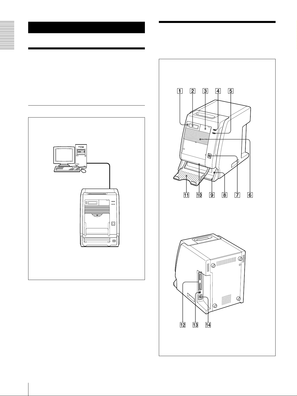
Basic Application Example
Computer: provides
image data for printing
and printer control
signals
For details, refer to the pages indicated in parentheses.
Front panel
UP-DR100 Digital Color Printer
Rear panel
32
Features / P art Names a nd Functions
Page 5
A ALARM indicator (52)
Lights in green when the system is initialized, or in
red when an error , such as a pa per jam , occu rs.
F Ventilation holes (49)
Behind the ventilation holes panel, there is a builtin fan to prev ent the therm al head from o verheating
B Information Display (42 , 46, 52)
Displays the number of pages printed, or the
amount of paper and ink ribbon remaining.
Messages are displayed when an error or warning
condition occurs.
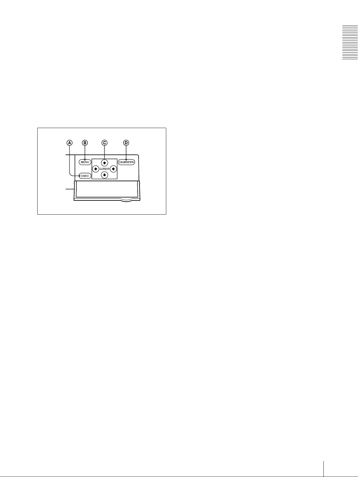
C Operation panel door
Pull the top edge to open the operation panel doo r.
Operation panel with door open
A EXEC Button
Press this button to print the gray scale adjustm ent
pattern.
B MENU B utton (46)
Press to display the number of pages printed or the
amount of paper and ink ribbon remaining.
Pressing the MENU button changes the printer to
the off-line mode and turns the ONLINE indicator
off.
C Cursor Buttons (46)
Press t h e s e bu tt ons to select th e item to be
displayed on the information display.
D CALIBR ATION button
Press this button to adjust the gray balance.
D ONLINE indicator (4 2, 46)
Lights in green when the printer is controlled only
by the computer in the on-line mode.
This indicator goes off whe n the printer go es offline, for example, when you press the M ENU
button to display the num ber of pages printed or the
amount of paper and ribbon remaining.
G FEED button (40, 43)
Press and hold this button for more than one
second just after you r ep lace the pap er an d ink
ribbon. Several sheets of blank paper are then fed
through. In this way, soiled paper at the beginning
of the roll will be eliminated, and paper improperly
loaded at an angle will be straightened in the paper
path. Also, pressing the FEED b utton for more than
one second during printing results in cancelling the
number of printings set and clearing the ima ges
stored in the memory. The pr inter stops pr inting
when the page currently printing is completed and
ejected.
H !POWER switch (42)
Press this switch to turn the printer on or off.
I Paper scrap tray (34)
A margin of about 10mm is put between the current
printout and the next printout from the paper roll.
This margin o f paper is cut of f and ejected into the
paper scrap tray.
J Paper Output Slot
Printed pages are output from the printer here.
K Paper Outpu t Tray (34)
Prin te d pages are output into th i s t r a y.
L SCSI Connectors (50-pin, half pitch) (35, 36)
Connect the com puter used to control the printer
and connect other SCSI de vices with SCSI cables to
one of these connectors. The second co nnec tor is
used as a pass-through connector w hen daisy
chaining with other SCSI de vices. If only one of the
SCSI connectors on the printer is used, the internal
terminator should be enabled b y c h anging the
appropriate DIP switch setting, see “D IP S w itch
Settings” (page 35).
M DIP Switch (35, 36)
Determines the SCS I device ID number o f the
printe r, and sets the internal te rminator on o r off.
See “DIP Switch Settings” (page35).
N - AC IN (Power So urce) Connector (36)
Connect the supplied power cord here.
Introduction
E PRINT Indicator (42)
Lights in green while printing.
Part Names and Functions
33
Page 6
Preparation
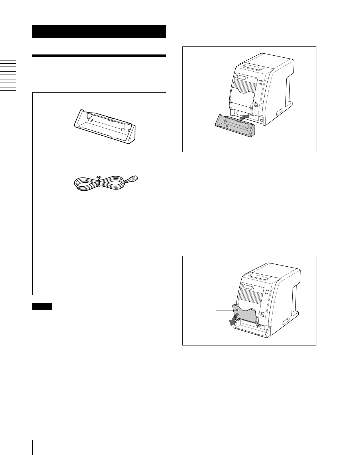
Assembly
Mount the paper scrap tray on the printer.
Supplied Accessories
Make certain you have recei ved the follow ing
accessories:
Preparation
Paper Scrap Tray (1)
Paper scrap tray
To remo v e the Paper scrap tray
Power Cord (1)
CD-ROM (1)
Operating Manual (1)
Software License Agreement (1)
Warranty Card (1)
Service and Customer Support
Information (1)
Hold both ends of the paper scrap tray and pull it
forward.
Paper output tray
The paper output tray supplied with the printer is
designed to accumulate only one printed she et for the
UPC-R35 and U PC-R46 printing packs. When using the
UPC-R35 or U PC-R46, open the paper output tray to
hold the printout by pressing it down. When using the
UPC-R57, be sure to close the paper output tray.
If you wa nt to accumulate 2 or more printed sheets
regardless of the type of printing pack used, use the
UPA-DR100PS PRINT STACKER (not sup plied).
Notes
• When taking out the printer , be careful not to hurt your
back.
• The packaging materials are needed when
transporting the printer, so we suggest you keep them .
• Before moving the printer , remo ve the ink ribbon and
paper.
34
Supplied Accessories
Paper output
tray
Paper and ink ribbon
For detailed information on how to install the ink ribbon
and paper, see “Loading the Paper and Ink Ribb on” on
page 37.
Page 7
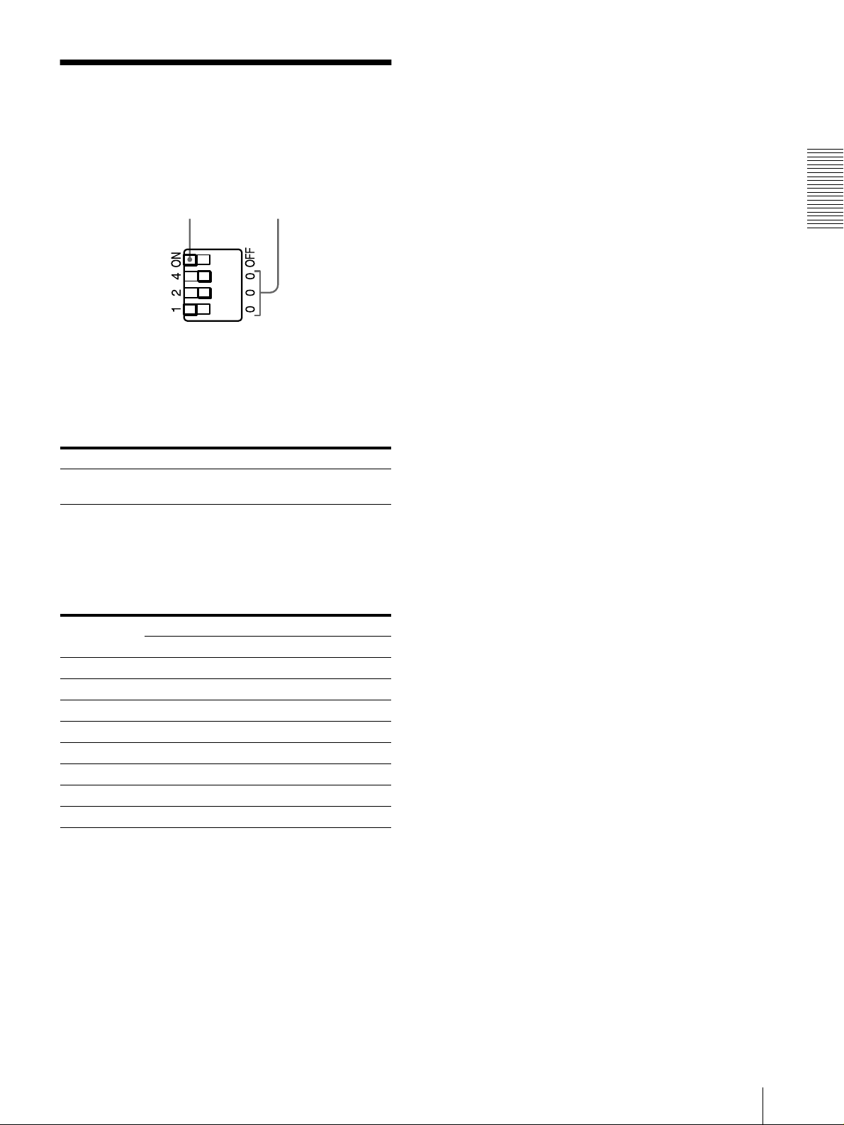
DIP Switch Settings
Set the SCSI ID with the DIP sw itches on the side panel.
The DIP switches are set as follow s whe n shipped from
the factory.
Terminator
SCSI ID
T erminator ON/OFF S etting
When the printer is connected as the terminating device
on the SCS I bus, set the termin a t o r t o t h e ON positio n.
Otherwise, set it to the OFF position.
Switch ON OFF
TERMINATOR Internal Terminator ONInternal Terminator
OFF
SCSI ID Setting
Set the printer SCSI ID so that it is dif ferent from all
other devices on the SC SI bus.
If two devices have the same SCSI ID, malfunctions
may result.
Preparation
SCSI ID SCSI ID Switch
124
0000
1100
2020
3120
4004
5104
6024
7124
The SCSI ID is set to 1 as the f actory setting.
DIP Switch Settings
35
Page 8

Connections
The UP-DR100 ca n be conne cted to com puters and
peripheral devices equipped with a SCSI interface.
Computer
Notes
• Before making conn ections, alw a ys turn off all
SCSI Cable
(not supplied)
connected devices.
Preparation
• Connect the pow er c ord last.
• Refer to the operating manual o f each d evice for
details of connections between the printer, computer
To SCSI
connector
To disconnect
and peripherals.
• SCSI cable connectors should b e firmly mated at each
end.
• The total length of SCSI cables connected to a single
host computer should not be longer than 3 meters.
• When connecting o nly the printer to a sing le host
computer, the SC SI cable shou ld not be longe r than 1
meter.
• To print, a driv er is required that co rresponds to the
DIP Switch
a)
hardware environment in wh ich the p rinter is to be
used.
To -AC IN
terminal
Power Cord (supplied)
To AC power output
a) When connecting the printer at the end of the SCSI bus,
set the internal terminator to ON. (“DIP Switch Settings”
on page 35)
Note
The proper SCSI cab le to use depend s on the connected
computer or the peripheral de vice. Refer to the m anuals
for details.
When turning po w er on
Turn on any peripheral devices before turning the
computer on. Mak e sure that every device in the SCSI
chain is turned on.
36
Connections
Page 9
Operation
Loading the Paper and
Ink Ribbon
Before using the printer for the first time, conf irm tha t
you have all of the acce ssories, and assem ble them as
described on page 34.
After connecting the printer as described on page 36,
load the paper and ink ribbon follow ing the steps belo w
to prepare for actual printing.
These steps are not required ev e ry tim e y ou p rint, bu t
only as necessary.
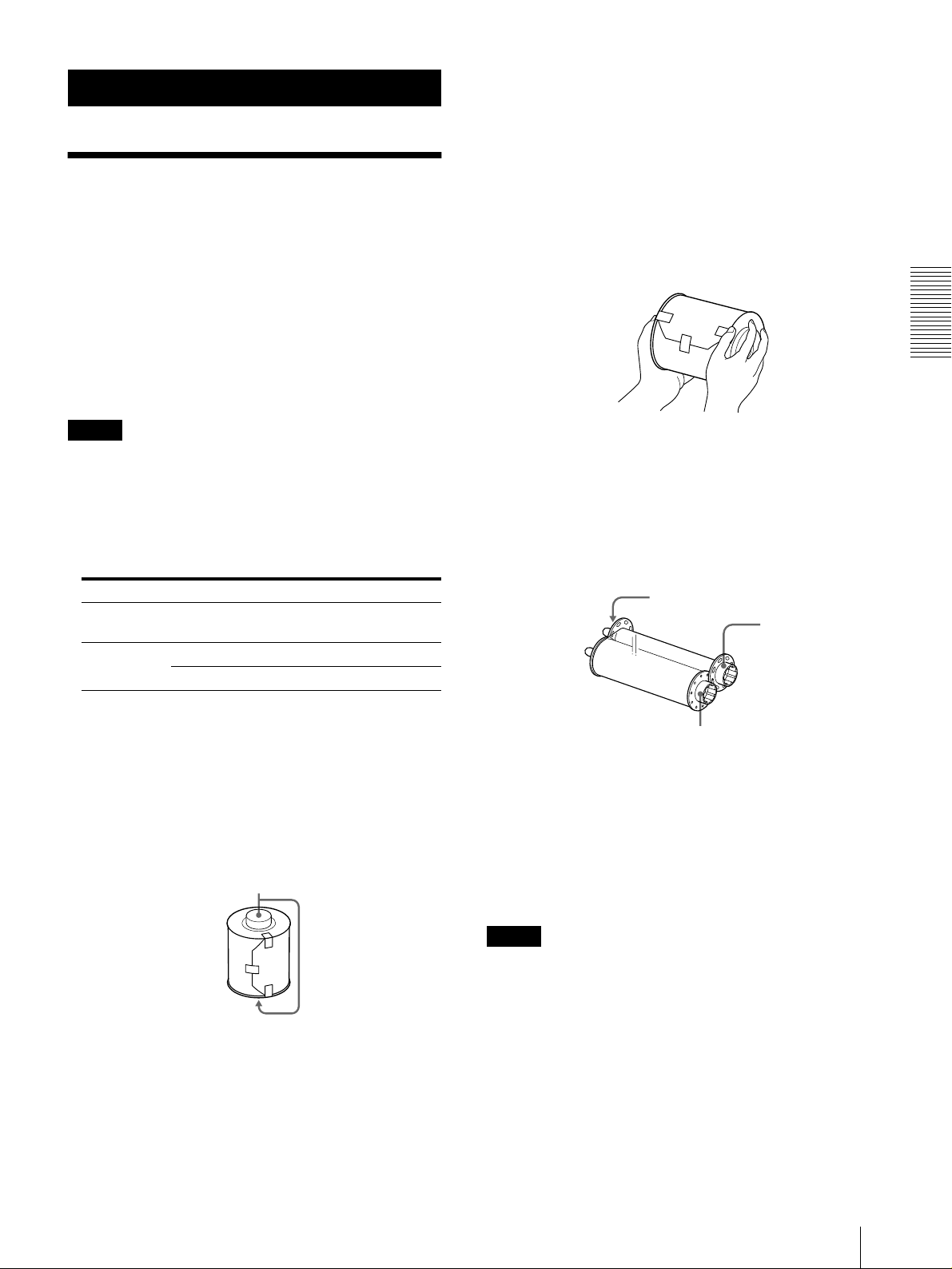
• Hold the right and left flanges of the paper roll so that
you do not drop it, because it is heavy. Dropping m ay
result in an injury and may cause accumulation of dust
on the paper. Any dust on the printing surface will
result in poor printout quality .
• A built-in IC chip is located around one side of the
Be careful not to hurt the IC
flange of the paper roll.
seal or gi ve it a shock.
seal or gi ve it a shock.
seal or gi ve it a shock.seal or gi ve it a shock.
Be careful not to hurt the IC
Be careful not to hurt the IC Be careful not to hurt the IC
If you do, you may not be able
to use the ink ribbon any m ore.
Hold the right and left flanges with both hands.
Operation
Notes
• The printing pack contains an ink ribbon and one
paper roll. Use the ink ribbon and the paper roll in the
carton as a set. Do not mix w ith othe r varieties of
ribbon or paper . (“Ink Ribbon an d Paper” on page 51.)
• Each printing pack allow s y ou to p rint the follo wing
number of sheets.
Print pack UPC-R35 UPC-R46 UPC-R57
Printing
capacity
Print size 89
400 350 205
127 mm 102×152 mm 127×178 mm
×
5 inches 4×6 inches 5×7 inches
3.5×
• The number of printouts that can be p rinted may not
be guaranteed if you replace the ink ribbon and pap er
before the ink ribbon and paper run out.
• Place the paper roll vertically with flanges facing up
and down. If you place the paper roll horizontally , the
paper may roll around and f all. This m ay c ause an
injury .
Flanges
• Do not detach the blue and pink sp ools of the ink
ribbon until you start loading the ink ribbon
• A built-in IC chip is located around one side of the
Be careful not to hurt the IC seal or
pink spool.
give it a sho ck.
give it a sho ck.
give it a sho ck.give it a sho ck.
Be careful not to hurt the IC seal or
Be careful not to hurt the IC seal or Be careful not to hurt the IC seal or
If you do, you may not be able to use
the ink ribbon any more.
IC seal in which the IC
chip is built
Pink spool
Blue spool
Loading the paper and ink ribbon
When you use the printer for the first time, load the
paper and ink ribbon.
For detailed information on h ow to remove the paper
and ink ribbon, see page 41.
Note
Be careful that your fingers or clothes don’t get caught
in the front door or front door catch.
Loading the Paper and Ink Ribbon
37
Page 10

Pull the top of the front door to open it.
1
Remove the labels.
Load the paper after matching the colors of the
flange of the paper roll and the flange holder of
the printer correctly.
Operation
Pull the cover up .
2
Thermal head
After removing the labels attached a t both sides of
3
the paper roll, place the paper roll in the paper
holder.
Place the paper roll in the paper holder, so the pink
flange is on the right and the blue flange is on the
left.
Caution
Since the thermal head is still very hot just after
printing is finished, be careful not to touch the
thermal head when placing the paper roll in the
paper holder .
Remov e the label attached a t the tip of the paper,
4
then, while holding both ends of the paper, insert
the paper into to the slot. Feed in the paper with
your hand until the marking hole app ears.
Roll the paper in properly so that it goes
in straight.
38
Loading the Paper and Ink Ribbon
Marking hole
Page 11

Note
Be sure to remove all of the seals attached to the
paper roll. A seal remaining inside the printer may
cause problems.
Close the cover.
5
Confirm that the tip of the paper appears.
Hold both spools and push the blue spoo l into the
6
blue spool holders.
Insert the left side of the blue spool first,
then the right side and push it until it clicks.
Operation
If the tip of the paper protrudes from the platen
roller, be sure to insert the tip of the paper under the
roller s.
Rollers
Platen roller
Caution
Since the thermal head is still very hot just after
printing is finished, be careful not to touch the
thermal head when loading the ink ribbon .
Detach the pink spool from the b lue spoo l. Pull it
7
upward and w ind it until the transparent part (the
laminating part) comes to the po sition illustrated,
and push it into the pink spool holders.
Insert the left side of the pink spool first,
then the right side and push it until it clicks.
Note
Do not touch the printing surface of the pap er roll
in the paper holder after loading it. Sweat or dust
from your hands may cause a deterioration in the
quality of the printout.
The black marks should show on
the front of the pink spool.
Transparent part (the laminating
part)
Loading the Paper and Ink Ribbon
39
Page 12

After confirming that the sp ools have been prop erly
8
inserted, remove any slackness from the ink ribbon.
After seve ral sheets of paper are fed out, the printer
is ready to print.
If you open the fron t door du ring ope ration
Wind the blue spool.
When you open the front do or after starting to use the
printer just after loading the paper and ink ribbon, the tip
of the paper may protrude. In that case, push the paper
back so that the length of the paper protruding is less
than 5 cm, then close the front door.
If you close the door with the paper protruding, the
printed paper will not be ejected correctly. This causes
paper jamming.
Operation
Push the paper
back so that the
Close the front door.
9
Tu rn o n the p rinter, if it is turned off.
When you load a b rand new paper roll and ink
length of the
paper protruding
is less than 5 cm
(2 inches).
ribbon, the printer feeds a certain amount of the
paper and is then ready to print.
When you load partially used p aper roll and ink
ribbon, go to step 10.
Note
Close the front door so that both sides of the front
door are completely locked. An unlocked door may
cause a malfunction of the printer.
Confirm that READY appears on the information
10
display.
Then, to straighten the paper, which might hav e
been loaded at angle, keep pressing the FEE D
button for more than one se cond.
Note
Be sure to do this after loading a paper roll used
partially .
FEED button
Note
Be careful not to touch the printing surface of the paper
when pushing it back. Sweat or d ust from your hands
may cause a deterioration in the quality of the printout.
Notes on storage
• Avoid placing the printer where subject to:
high temperatures,
high humidity or dust,
direct sunlight.
• After opening the bag, use the ribbo n and the paper as
soon as possible.
• When storing after partial use, put the ribbon and the
paper back in their respective bags.
40
Loading the Paper and Ink Ribbon
Page 13

If the ribbon breaks during use
The remaining ribbon can be used after repairing it with
adhesive tape.
Pull out the lower ribbon of the b lue spoo l, attach
1
one edge of a strip of adhesiv e tape o ver the entire
end of the ribbon, then attach the other ed ge of the
adhesive tape on the end of the upper ribbo n of the
pink spool.
Wind the spool
to feed the
ribbon out.
Attach one edge of adhesive
tape over the entire end of the
ribbon and attach the other
edge of the adhesive tape on
the end of the upper ribbon.
Removing the ink ribbon and paper
Close the paper output tray.
1
Remov e the scraps o f paper e jected and
2
accumulated on the paper scrap tray.
Note
If scraps of paper hav e accu mulated on the paper
scrap tray , the front door may not open com pletely.
Pull the top of the front door to open it.
3
Push the right blue spool to the left and pull it
4
toward you to rem o ve the blue spool of the ink
ribbon.
Operation
Turn the lo wer blue spool in the direction of the
2
arrow to remo ve the slackness of the ribbon.
Wind the spool in
the direction of the
arrow to remove the
slackness of the
ribbon.
The ribbon is ready to be used. Depending on the
position of the break in the tape, the ribbon for one
sheet of printed paper may be lost.
W ind up the loose ink ribbo n.
5
Loading the Paper and Ink Ribbon
41
Page 14

Push t h e ri g ht pink spoo l to the left and p ull it
6
toward you to rem o ve the pink spool of the ink
ribbon.
Attach both pink and blue spoo ls of the ink ribbon.
Operation
Printing from the
Computer
Before s ta rting to prin t
• Confirm that the printer and computer are connected
(page 36).
• Confirm that the paper and the ink ribbon a re correctly
installed (page 34).
• Confirm that the com patible ink ribbon and p rinting
paper are installed (page 51).
Printing
information display
Remov e the paper .
7
1 Pull the cover up.
2 Turn both flanges of the paper toward the inside
to wind the remaining paper.
3 Remove the paper roll.
Wind the remaining paper by turning the
flanges of the paper roll in the direction of
the arrow 2.
ONLINE indicator
1
Tu rn o n the printer and computer .
1
After a few seconds, the follo wing m essage shou ld
appear on the information display. When READY
is displayed and the ON LINE indicator is lit, the
printer is ready to print.
Caution
Since the thermal head is still very hot just after
printing is finished, be careful not to touch the
thermal head when removing the paper roll from
the paper holder.
42
Printing from the Computer
Print size
Displays the remaining amount of
paper or ink ribbon, whichever is less.
Page 15

Identification of the printing pack currently
being used on the informa tion display
Display on the
information displa y
R35 UPC-R35
R46 UPC-R46
R57 UPC-R57
Notes
Printing pack
• Turn the printer on first.
• Don’t turn the printer on again within 5 seconds
after turnin g it off.
• Do not turn the compu ter off and on again while
it is accessing a hard or floppy disk.
Send the image data from the com pu ter to be
2
printed.
The printer starts printing.
1 While the printer is recei ving the image data,
the following message should appear .
Indicates the image data is being
transferred.
: Indicates 20% of the total amount of image
data. In the above example, 60% of the total
amount of image data has been transferred.
3 After printing is finished, the printed paper is
ejected from the output slot.
The printing time depends on the print size, ink
ribbon and the paper .
Once printing has been completed, the PRINT
indicator goes off and READ Y appears on the
information display again.
Notes
• Do not allow 2 or more printed sheets to accum ulate at
the output slot, as it could cause a jam. If you allow 2
or more printed sheets in the paper tray, the printed
paper jams around the output slot. If printed paper is
caught around the output slot, remove it. Or remove
the printed sheets accumulated in the paper tray, as
required.
• When the UPC -R57 printing pack is used, close the
paper output tray.
To stop sending the im a ge d ata o r to s to p
printing m id way
Press and hold the FEED button for more than one
second. The page currently being printed is com pleted
and ejected. After the printout is ejected, the information
display returns to READ Y. The im age data stored in the
memory and the number of printings set in the queue are
cancelled.
Operation
2 The printer starts printing the transferred image
data as soon as the print comm and is sent from
the computer .
The PRINT indicator lights and the following
message should appear .
Number of pages to be printed
The color indication changes as the color printing
procedes:
StarttYELLOWtMAGENTAtCYANtLAMIt
Finsih.
About memory
Since the printer has memory for im a ge data sp ooling,
image data to be printed can be transferred to the printer
while printing an image.
Printing from the Computer
43
Page 16

If the printer doe s n o t prin t
The printer cannot print in the follow ing cases:
• When the remaining amount of ink ribbon or the
quantity of printing is displayed on the information
display because the MEN U button w as pressed and the
printer is off-line, the printer cannot receive a print
command from the computer.
• When an error m essage is displayed on the
information display, you cannot operate the printer .
T ake rem edies according to the advice given in “Error
and W arning Messages” on page 52.
Adjusting Gray Balance
The gray balance differs betwee n different packages
where ink ribbons and papers are co ntained a s a set. To
avoid im balance, use the ink ribbon w ith the pa per that
is supplied as a set in the same package. Also, when a
new ribbon and pape r are loaded , we recommend that
the gray balance be adjusted. The gray balance of the
printer is set to No.0 as the factory setting. This setting
is retained even w hen the printer is turned off.
Notes on storing your printouts
• Avoid exposure to direct sunlight, or conditions of
high temperature and high hum idity, which could
Operation
cause the colors to fade.
• Avoid applying tape to a printout, and avoid contact
with plastic objects such as erasers and desk mats.
• Do not allow alcohol or other volatile or ganic solvents
to come into contact with the printouts.
Note
The gray balance of images cann ot be ad justed during
printing.
2,7,8,9,10
3
Press the CALIBRATION button.
1
The ONL IN E indicator go es off and the printer is
switched to off-line.
1,6,11
ONLINE indicator
44
Adjusting Gray Balance
Press the F and f buttons to select GRAY PATCH
2
PRINT.
Press F and f to display GRAY PATCH PRINT.
Press the EXEC button.
3
The printer returns to the on-line mode and starts
printing.
When using the UPC-R35 or UPC-R46, gray
adjustment patterns Group A and Group B are
printed on two sheets separately.
When using the UP C -R 57, g ray patterns G roup A
and Group B are printed on one sh eet.
Page 17

Look at the printout of Group A to de term ine the
4
best gray balance from this group.
Next, look at the printout of Group B to determine
5
the best gray balance from this group, too.
Press the CALIBRATION button.
6
The ONLINE indicator g oes off and the printer is
switched to off-line.
Press the F and f buttons to select GRAY A DJUST
7
[A].
The printer enters the gray balance adjustment
mode.
Press F and f to display GRAY
ADJUST [A].
Press the G and g buttons to display the pattern
8
number determined in step 4.
For example, select 18 if you determined that
pattern No. 18 in the sample pro vides the best gray
balance.
Press the G and g buttons to display the pattern
10
number determined in step 5.
For exam ple, select 39 if you determined that
pattern No. 39 in the sample provides the best gray
balance.
Press G and g to display 39.
Press the CALIBRATION button.
11
The p r inter returns to the on-line mode, and the
ONLINE indicator lights.
Operation
Press G and g to display 18.
Press the F and f buttons to select GRAY A DJUST
9
[B].
The printer enters the gray balance adjustment
mode.
Press F and f to display GRAY
ADJUST [B].
Adju sting Gray Balance
45
Page 18

Displaying the Total
Quantity of Pages
Printed and Remaining
Amount of Ink Ribbon or
Paper
Displaying the Quantity of Pages
To display the total number of printings
made so far since you started to use the
printer:
Select “TOTAL PRINTS”.
Press F and f to display
TOTAL PRIN TS.
Total number of printings
Printed
Operation
The total number of pages printings done since turning
on the printer can be displayed. If no printings have bee n
done since the printer was turned on, “0” is displayed o n
the information display. Also, the total number of
printings made so far since yo u started to use the printer
can be displayed.
1,3
2
ONLINE indicator
Press the MEN U button after confirming.
3
The printer returns to the on-line mode, and the
ONLINE indicator lights.
Displaying the Remaining Amount
of Paper or Ink Ribbon
The remaining amount of pap er or ink ribbon can be
displayed on the information display.
1,3
2
ONLINE indicator
Press the MEN U button.
1
The ONLINE indicator goes off and the printer is
switched to off-line.
Press the F and f buttons to select the item you
2
want to be displayed.
T o display the total number of printings
since turning on the printer:
Select “CURRENT PRINTS.”
Press F and f to display CURRENT PRINTS.
Total number of printings since turning on the
printer
46
Displaying the T otal Quantity of Pages Printed and Remaining Amount of Ink Ribbon or Paper
Pres s the MENU button.
1
The ONL IN E indicator go es off and the printer is
switched to off-line.
Press the F a nd f buttons to select the item you
2
want to be displayed.
Page 19

T o display the remaining amount of the ink
ribbon:
Select “RIBBON REM AIN .”
Press F and f to display
RIBBON REMAIN.
Displaying the Firmware
Version of the Printer
The version of the firmware of the printer can be
displayed.
Remaining amount of the ink
ribbon
T o display the remaining amount of paper:
Select “PAPER REMAIN”.
Press F and f to display
PAPER REMAIN.
Remaining amount of paper
Press the MENU button after conf irming.
3
The p r inter returns to the o n - l i n e mode, and t h e
ONLINE indicator lights.
Note
If the ink ribbon and paper have not been used from
the beginning, the remaining amount displayed
may be incorrect.
1,3
Press the MEN U button.
1
The ONLINE indicator goes off and the printer is
switched to off-line.
Press the F and f buttons to display VERSION.
2
Press F and f to display VERSION.
2
ONLINE indicator
Operation
Version of the firmware of the printer
Press the MEN U button after confirming.
3
The p r inter returns to the on-line mode, and the
ONLINE indicator lights.
Access the follo wing si te to get the la test inf ormation on
the printer.
http://www.sony.co.jp/DP-driver-E/
Displaying the Firmware Version of the Printer
47
Page 20

Miscellaneous
Precautions
Note
Four protruberences placed on the rear of the printer
are provided to prevent the ventilation holes being
covered o ver by a wall, etc., when installing the p rinter
These protruberences are not to be
near the wall.
used as feet to install the printer laying on its back.
used as feet to install the printer laying on its back.
used as feet to install the printer laying on its back.used as feet to install the printer laying on its back.
These protruberences are not to be
These protruberences are not to be These protruberences are not to be
Miscellaneous
Safety
• Operate the printer using the power source specif ied in
“Specifications” (p age 51)
• Be careful not to damage the power cable b y placing
or dropping heavy objects on it; it is dangerous to use
the unit with a damaged power cable.
• If you do not intend to use the unit for a long time,
disconnect the pow er cable.
• Unplug the power cable by grasping the plug , not the
cable itself.
• Do not disassemble the unit. There is a d anger o f
electric shock from the internal parts.
• Be careful not to spill water or other liquids on the
unit, or to allow com bustible or metallic material to
enter the cabinet. If used with foreign matter in the
cabinet, the unit is liable to fail, or present a risk of fire
or electric shock.
• If the unit malfunctions or if a foreign body falls into
the cabinet, disconnect the power im m ed iately and
consult your Sony service f acility or your Sony dealer .
Installation
• Avoid placing the unit in a location subject to:
– mechanical vibration
– high humidity
– excessive dust
– direct or excessive sunlight
– extremely high or low temperatures
• Ventilation holes are provided on the back of the unit
to prevent the u nit from o verheating. Be careful not to
obstruct them with other objects or by covering the
unit with a cloth etc.
Protruberences
On condensation
• If the printer is subjected to wide and sudden ch anges
in temperature, such as when it is moved from a cold
room to a warm room or when it is left in a room with
a heater that tends to produce large amounts of
moisture, condensation may form inside the printer. In
such cases the printer will probably not w ork properly,
and may ev en de velop a fau lt if you persist in using it.
If moisture condensation forms, turn of f the power and
leave the printer standing for at least one hou r.
• If the printing pack is subjected to wide and sudden
changes in temperature, condensation m ay form on
the ink ribbon or paper inside. This will cause the
printer to malfunction. Also if the printing pack is
used in this state, spots are likely to appear on the
printout.
• To store a half-used printing pack, replace it in its
original packing and reseal the package. If possible,
keep the sealed printing pack in a cool, dark loca tion.
To subsequently use the printing pack , place it, in its
sealed package, in a warm room for sev eral hours.
Doing so prevents condensation from forming wh en
the printing pack is removed from its package.
48
Precautions
Page 21

On Transporting the Printer
Wash the filter with water to remove the dust.
2
Do not transport the printer with the supplied
accessories attached. Doing so may cause a malfunction.
Cleaning
Note
Be sure to turn off the power of the printer before
cleaning it.
Cleaning the cabinet
Clean the cabinet, panel and controls with a soft dry
cloth, or a soft cloth lightly moistened with a mild
detergent solution.
Do not use any type of solv en t, such as alcohol or
benzine, which may damage the finish.
Cleaning the filter
Ventilation holes are provided on the front and rear of
the printer.
When the messa ge “HEAD IN COOLING” begins to
appear on the information display frequently, clean the
filter placed on the front pan el of the printer. If the filter
is dirty, the time required for cooling the the rmal head is
lengthened and this causes the printing time to becom e
longer.
Open the paper output tray and remo ve the fan
1
cover , then the filter.
Note
Do not rub the netting of the f ilter roughly.
After the filter has been dried completely, reset the
3
filter and fan cov er on the front pan el as the y were.
Reset the filter on the fan cover correctly.
Note
Be sure to attach the filter onto the fan co ver correctly . If
not, dust may accumulate on the printout. This may
cause a deterioration of the picture quality.
Miscellaneous
Fan cover
Paper output
tray
Cleaning the platen roller, thermal head
and pinch roller
When a v ertical white stripe appe ars on the printout or
the color distribution becomes une ven, clean the therm al
head and the platen roller .
It is recommended that you clean the thermal head,
platen roller and pinch roller whenev er replacing the ink
ribbon and paper .
Filter
Fan cover
Precautions
49
Page 22

To clean the therm a l hea d :
Clean the thermal head heating elem en ts, IC co ver and
ribbon guide gently with a soft cloth.
T o c lean the platen r oller:
Clean the platen roller gently with a soft cloth m oistened
with alcohol.
Miscellaneous
Thermal head heating elements
Ribbon guide
IC cove r
If white stripes or scratches appears on the
printout:
When you m ak e p rintouts using the U PC-R46 selflaminating color printing pack, after you have used
several rolls of the U PC -R35 /UP C-R 57 self-lam inating
color printing pack, the printout quality may d eteriorate,
for example, white stripes or scratches m ay appear on
the printout.
In such a case, clean the thermal head gently with a soft
cloth moistened with alcohol.
Clean the platen roller gently with a soft cloth
moistened with alcohol while turning the platen roller.
T o c lean th e pinch r oller:
Clean the pinch roller gently with a soft cloth moistened
with alcohol while turning the pinch roller.
Clean both ends of the thermal head gently
with a soft cloth moistened with alcohol.
Pinch roller
50
Precautions
Page 23

Ink Ribbon and Paper
Specifications
The ink ribbon and paper are supplied as a set in the
same package and are intended to be used together.
UPC-R35 Self-Laminating Color Printing Pack
Contains color ink ribbon and paper.
Ink ribbon for printing: 1 roll
L-size print paper: 1 roll
UPC-R46 Self-Laminating Color Printing Pack
Contains color ink ribbon and paper.
Ink ribbon for printing: 1 roll
King-size print paper: 1 roll
UPC-R57 Self-Laminating Color Printing Pack
Contains color ink ribbon and paper.
Ink ribbon for printing: 1 roll
2L-size print paper: 1 roll
Note
When using the UPC-R57 Self-L am inating Color
Printing Pack, close the paper tray.
Printing capacity
Printing
pack
Printing
capacity
Print size 89
UPC-R35 UPC-R46 UPC-R57
400 350 205
127 mm 102×152 mm 127×178 mm
×
5 inches 4×6 inches 5×7 inches
3.5×
However the number of sheets that can be printed may
not be guaranteed if you replace the ink ribbon and paper
before the ink ribbon and paper run out.
Power requirements
100-120 V/220-240 V AC, 50/60 Hz
Current consumption
Max. 2.7 A/1.2 A (w hile printing)
Operating temperature range
5 to 35°C
Operating humidity range
20 to 80%
External dimensions
Approx. 280 × 362 × 458 mm (WHD)
1
/8×14 3/8×18 1/8 inches)
(11
Weight Approx. 17 kg (37lb 8 o z) (printer
only)
Printing system Dye sublimation thermal transfer
Thermal head 13.1 dot/mm , 2048 e lemen ts (334 d pi)
Gradations 8 bits each for yellow, magenta and
cyan
Picture size UPC -R 35: 89 × 127 mm (3.5 × 5
inches)
UPC-R46: 102 × 152 mm (4 × 6
inches)
UPC-R57: 127 × 178 mm (5 × 7
inches)
Printable pixels UPC-R35: 1170 × 1670 dots
UPC-R46: 1341 × 1999 dots
UPC-R57: 1670 × 2391 dots
Printing time UPC-R35: A pprox .23 sec .
UPC-R46: A pprox .24 sec.
UPC-R57: A pprox .36 sec.
Input connector A C IN (for power)
Control connectors
SCSI-2 interface × 2 (50-pin, half-
pitch)
Accessories supplied
Paper scrap tray (1)
Power Cord (1)
CD-ROM (1)
Software License A g reement (1)
Operating Manua l (1)
Warranty Card (1)
Service and Custom er Support Info. (1)
Miscellaneous
Optional accessories
Self-Laminating Color P rinting P ack
UPC-R35
UPC-R46
UPC-R57
PRINT STACKER UPA-DR100PS
Ink Ribbon and Paper / Specifications
51
Page 24

Miscellaneous
SCSI-2 Interface
Connectors Tw o 50-pin, half-pitch
T e rm ina tor Internal (DIP switch enable/disable)
SCSI ID setting 0 to 7 (DIP switch selectable)
Transfer speed Max. 10 MB/sec (Fast SC S I)
Design and specifications are subject to c hange w ithout
notice.
Error and Warning
Messages
Error and warning m essag es app ear on the information
display under the following co nditions. Please tak e the
remedial actions shown next to the message to correct
the condition.
Error messages
When a problem occu rs, the A LARM indicator on the
front panel lights in red, and an error message appears
on the information display. Please take the remedial
actions shown next to the message to correct the
condition.
Message Description and Remedy
DOOR OPEN The front door is open.
tClose the front panel until it is
locked securely (page 40).
FEED ERROR Paper cannot be fed or ejected
correctly.
tLoad the paper roll correctly.
(page 43)
MECHA TROUBLE • The ink ribbon may break.
tRepair it with adhesive tape.
(page 41)
• The paper corresponding to the
designated number of sheets is
exhausted.
tLoad a new ink ribbon and paper
roll. (page 37)
• The ink ribbon corresponding to the
designated number of sheets is
exhausted.
tLoad a new ink ribbon and paper
roll. (page 37)
• Mechanical trouble has occurred in
the printer.
tThe ink ribbon and paper roll are
not loaded correctly. Load them
correctly. (page37)
tIf the message does not
disappear even after performing
the above remedy. Contact your
supplier or nearest Sony Service
Center.
MEDIA MISMATCH An incompatible ink ribbon and paper
are loaded .
tLoad the compatible ink ribbon and
paper roll taken from the same
package. (page 51)
NO PAPER The paper roll is not loaded.
tLoad paper roll.(page 37)
NO RIBBON The ink ribbon is not loaded.
tLoad an ink ribbon.(page 37)
52
Error and Warning Messages
Page 25

Message Description and Remedy
PAPER END The paper corresponding to the
designated number of sheets is
exhausted.
tLoad a new ink ribbon and paper
roll. (page 37)
PAPER ERROR • The paper corresponding to the
designated number of sheets i s
exhausted.
tLoad a new ink ribbon and paper
roll. (page 37)
• Something is wrong with the data
on the IC seal attached to the paper
roll.
tReplace the ink ribbon and
paper roll with a new ink ribbon
and paper roll. (page 37)
RIBBON END The ink ribbon corresponding to the
designated number of sheets is
exhausted.
tLoad a new ink ribbon and paper
roll. (page 37)
RIBBON ERROR • The ink ribbon may break.
tRepair it with adhesive tape.
(page 41)
• Something is wrong with the data
on the IC seal attached to the paper
roll.
tReplace the ink ribbon and
paper roll with a new ink ribbon
and paper roll. (page 37)
• The ink ribbon corresponding to the
designated number of sheets i s
exhausted.
tLoad a new ink ribbon and paper
roll. (page 37)
Warning messages
When a wa rning condition occurs, the warning message
appears, but the AL ARM indicator does not light. The
remedy is listed below ne xt to ea ch message.
Message Description and remedy
HEAD IN COOLING The thermal head is too hot.
tWait for the message to disappear.
Printing will then resume
automatically.
PLEASE WAIT The printer ejects the paper because
the printer has received the stop
command or the printer stops printing
due to some problem.
tWait for the message to disappear.
Troubleshooting
Before submitting the product for repair, p lease recheck
the following. If the unit still does not operate pro perly,
contact your supplier or nearest Sony Service Center .
Problem Cause and Remedy
Cannot load the paper You may be trying to load the paper
Cannot load the ink
ribbon
NO PAPER is
displayed ev en th ough
paper roll is loaded.
NO RIBBON is
displayed ev en th ough
the ink ribbon is
loaded.
The image is printed
out of place on the
paper.
Paper is left even
though PAPER END
is displayed.
Ink ribbon is left e v e n
though RIBBON END
is displayed.
HEAD IN COOLING
is displayed
frequently.
A vertical white stripe
appears on the
printout.
The printed paper
cannot be ejected
correctly.
with the right and left sides reversed.
tLoad the paper after matching the
colors of the flange of the paper and
the flange holder of the printer
correctly. (page 39)
Y ou may be trying to load the spools of
the ink ribbon wrongly.
tLoad the ink ribbon after matching
the colors of the spools of the ink
ribbon and the spool holders of the
printer correctly. (page 39)
The paper roll is not loaded correctly.
tLoad the paper correctly. (page 37)
The ink ribbon is not loaded correctly.
tLoad the ink ribbon correctly.
(page 37)
The paper is loaded at an angle. Try to
eject several sheets of paper by
keeping the FEED button pressed for
more than one second after loading.
tEjecting the paper by pressing the
FEED button helps to put the
remaining paper in the correct
position. (page 40)
This is not a malfunction. Extra sheets
of paper are provided with each roll of
paper.
tRemove the remaining paper and
load a new ink ribbon and paper
roll. (page 37)
This is not a malfunction. Extra ink
ribbon is provided.
tRemove the remaining paper and
load a new ink ribbon and paper
roll. (page 37)
The filter may be dirty.
tClea n the filter. (page 49)
Dust may have accumulated on the
thermal head.
tClea n the thermal head elements
with a soft dry cloth. (page 49)
The printed pages are not ejected and
stacked properly on th e paper output
tray after they are cut.
tIt is recommended to use the UPA-
DR100PS PRINT STACKER (not
supplied) so that they are ejec ted
and stacked properly.
Miscellaneous
T roub leshooting
53
Page 26

Index
error message 52
warning message 53
A
Accessories supplied
assembly 34
confirmation 34
Paper Scrap Tray 34
Power Cord 34
Adjusting gray balance 44
B
Basic Application Example 32
C
Cleaning
cabinet 49
pinch roller 50
platen roller 50
thermal head 50
Connections 36
D
DIP Switch Settings
SCSI ID 35
terminator 35
Displaying
Index
quantity of printing 46
remaining amount of pa per or ink
ribbon 46
version of the printer 47
Operation 37
P
Paper and ink ribbon
loading 37
Part Names and Functions
Front panel 32
Operation panel door 33
Rear panel 32
Precautions
condensation 48
Installation 48
on transportation 49
Safety 48
Preparation 34
Printing 42
Printing pack
printing capacity 51
UPC-R35 51
UPC-R46 51
UPC-R57 51
R
Remaining Ribbon 46
S
SCSI ID 35
Specifications 51
O
F
Features 32
G
Gray balance 44
I
Ink ribbon
if the ribb on breaks 41
Ink ribbon and paper
displaying the rema ining a mount
46
loading 37
removing 41
usable printing pack 51
Introduction 32
M
Message
T
Troubleshooting 53
54
Index
Page 27

 Loading...