

Sony UNI-ONER580T2, UNI-ONER580T7, UNI-ONER520T2, UNI-ONER520T7, UNI-ONER550C2 User Manual
...
Installation and Operation Instructions for the following unitized outdoor camera models:
UNI-ONER / EP SERIES
Outdoor 24VAC Clear Dome
UNI-ONER580C2 Unitized SNC-ER580 pendant type, clear dome, with heater and blower
UNI-ONER550C2 Unitized SNC-ER550 pendant type, clear dome, with heater and blower
UNI-ONER520C2 Unitized SNC-ER520 pendant type, clear dome, with heater and blower
UNI-ONEP580C2 Unitized SNC-EP580 pendant type, clear dome, with heater and blower
UNI-ONEP550C2 Unitized SNC-EP550 pendant type, clear dome, with heater and blower
UNI-ONEP520C2 Unitized SNC-EP520 pendant type, clear dome, with heater and blower
Note: AC 24V power supply for the camera and the heater/blower is an installer/reseller
provided item. Please refer to page 3 Electrical Specifications for power consumption
details.
Note: Please note that to achieve the increased depth with the aspheric design for optimal
camera lens to capsule orientation, the capsule is slightly angled around the highest
section. This creates a ”line’, visible to the naked eye, around the upper most section
of the capsule. This “line” serves as the geometric center line used to insure proper
camera placement. It is not typically seen by the camera. However, this line maybe
visible in the camera image when camera’s above horizon tilt capability is used.
81-IN6710 06152012
IMPORTANT SAFEGUARDS
Read instructions - All the safety and operating
1.
instructions should be read before the unit is
operated.
Retain instructions - The safety and operating
2.
instructions should be retained for future reference.
Heed Warnings - All warnings on the unit and in the
3.
operating instructions should be adhered to.
Follow instructions - All operating and user instructions
4.
should be followed.
Electrical Connections - Only a qualifi ed electrician
5.
should make electrical connections.
Attachments - Do not use attachments not
6.
recommended by the product manufacturer as they
may cause hazards.
Cable Runs- All cable runs must be within permissible
7.
distance.
Mounting - This unit must be properly and securely
8.
mounted to a supporting structure capable of
sustaining the weight of the unit.
Accordingly:
The installation should be made by a qualifi ed
a.
installer.
The installation should be in compliance with local
b.
codes.
Care should be exercised to select suitable
c.
hardware to install the unit, taking into account both
the composition of the mounting surface and the
weight of the unit.
Be sure to periodically examine the unit and the
supporting structure to make sure that the integrity of the
installation is intact. Failure to comply with the foregoing
could result in the unit separating from the support
structure and falling, with resultant damages or injury to
anyone or anything struck by the falling unit.
UNPACKING
Unpack carefully. Electronic components can be
damaged if improperly handled or dropped. If an item
appears to have been damaged in shipment, replace
it properly in its carton and notify the shipper.
Be sure to save:
The shipping carton and packaging material.
1.
They are the safest material in which to make
future shipments of the equipment.
These Installation and Operating Instructions.
2.
SERVICE
If technical support or service is needed, contact
Sony at the following number:
TECHNICAL SUPPORT
8:15 AM to 7:30 PM
(EASTERN TIME)
1- 800 - 883 - 6817
SAFETY PRECAUTIONS
CAUTION
RISK OF ELECTRIC SHOCK
DO NOT OPEN
CAUTION: TO REDUCE THE RISK OF
ELECTRIC SHOCK, DO NOT REMOVE
COVER ( OR BACK). NO USER- SERVICEABLE
PARTS INSIDE. REFER SERVICING TO
QUALIFIED SERVICE PERSONNEL.
The lightning fl ash with an arrowhead
symbol, within an equilateral triangle, is
intended to alert the user to the presence
of non-insulated “dangerous voltage”
within the product’s enclosure that may be
of suffi cient magnitude to constitute a risk
to persons.
Este símbolo se piensa para alertar al usuario a la
presencia del “voltaje peligroso no-aisIado” dentro del
recinto de los productos que puede ser un riesgo de
choque eléctrico.
Ce symbole est prévu pour alerter I’utilisateur à la
presence “de la tension dangereuse” non-isolée dans la
clôture de produits qui peut être un risque de choc
électrique.
Dieses Symbol soll den Benutzer zum Vorhandensein der
nicht-lsolier “Gefährdungsspannung” innerhalb der
Produkteinschließung alarmieren die eine Gefahr des
elektrischen Schlages sein kann.
Este símbolo é pretendido alertar o usuário à presença
“di tensão perigosa non-isolada” dentro do cerco dos
produtos que pode ser um risco de choque elétrico.
Questo simbolo è inteso per avvertire I’utente alla
presenza “di tensione pericolosa” non-isolata all’interno
della recinzione dei prodotti che può essere un rischio di
scossa elettrica.
The exclamation point within an equilateral
triangle is intended to alert the user to
presence of important operating and
!!
maintenance (servicing) instructions in the
literature accompanying the appliance.
Este símbolo del punto del exclamation se piensa para
alertar al usuario a la presencia de instrucciones
importantes en la literatura que acompaña la
aplicación.
Ce symbole de point d’exclamation est prévu pour
alerter l’utilisateur à la presence des instructions
importantes dans la littérature accompagnant
l’appareil.
Dieses Ausruf Punktsymbol soll den Benutzer zum
Vorhandensein de wichtigen Anweisungen in der
Literatur alarmieren, die das Gerät begleitet.
Este símbolo do ponto do exclamation é pretendido
alertar o usuário à presença de instruções importantes
na literatura que acompanha o dispositivo.
Questo simbolo del punto del exclamaton è inteso per
avvertire l’utente alla presenza delle istruzioni importanti
nella letteratura che accompagna l’apparecchio.
!!
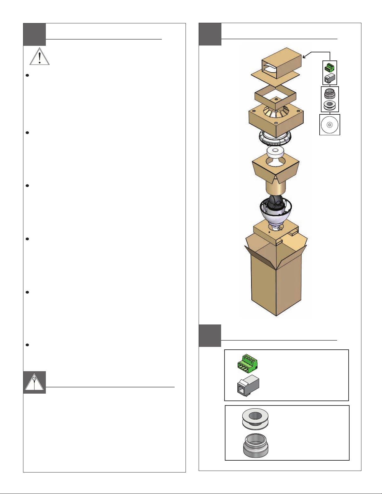
Contents of Box
Contents of Box Details
(1) 4 Pin Power Connector
(1) RJ45 Coupling
(1) Teflon Tape
(1) Pendant Gasket
CD
Electrical Specifications
Power 24VAC, Class 2 Only
UNI-ON
26 Watts at 24 VAC (Heater and Blower)
Camera: 25 Watts at 24VAC
UNI-ON
26 vatios en 24VAC (calentador y soplador)
Cámara: el 25 Watts a 24VAC
UNI-ON
26 watts à 24VAC (réchauffeur et ventilateur)
Camera: 25 Watts à 24VAC
UNI-ON
UNI-ON
26 Watt an 24VAC (Heizung und Gebläse)
Kamera: 25 Watt bei 24VAC
UNI-ON
26 watts em 24VAC (calefator e ventilador)
Câmara: de 25 Watts a 24VAC
UNI-ON
26 watt a 24VAC (riscaldatore e ventilatore)
Camera: 25 Watt a 24VAC
Operating Temperature Specifications
- 2 9 ° C t o 5 0 ° C ( - 2 0 ° F t o 1 2 2 ° F )
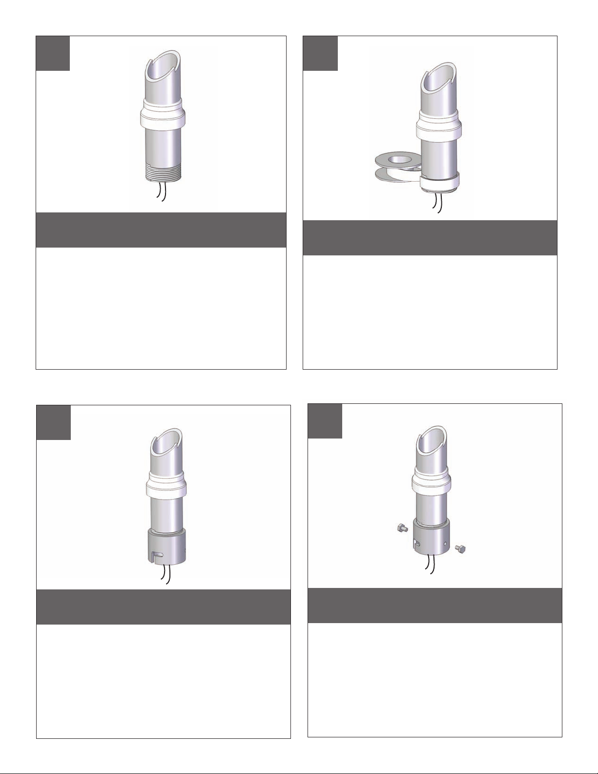
Mounting Preparation
Securely attach pendant pipe or the UNI-WMB1
(See block 9 when using UNI-WMB3). Pull wiring
through pipe and position grommet as shown.
• Con seguridad pipa pendiente de la fijación o el UNI-WMB1 (véase el bloque 9
para UNI-WMB3). Tire del cableado a través de la pipa y del ojal
de la posición como se muestra.
• Solidement pipe pendante d'attache ou l'UNI-WMB1 (voir le bloc 9 pour
UNI-WMB3). Tirez le câblage par la pipe et le canon isolant de position comme
montré.
• Sicher hängendes Rohr der Befestigungs oder das UNI-WMB1
(sehen Sie Block 9 für UNI-WMB3). Ziehen Sie Verdrahtung durch Rohr und
Positionsgummimuffe wie gezeigt.
• Firmemente tubulação do pendente do anexo ou o UNI-WMB1 (veja o
bloco 9 para UNI-WMB3). Puxe a fiação através da tubulação e do ilhó
da posição como mostrado.
• Saldamente tubo del pendente dell'attaccatura o il UNI-WMB1 (vedi il blocco
9 per UNI-WMB3). Tiri i collegamenti tramite il tubo ed il gommino di protezione
di posizione come indicato.
1
2
Wrap Teflon tape around the pipe threads
to ensure a tight seal.
• La cinta del Teflon del abrigo alrededor de la pipa rosca
para asegurar un sello apretado.
• La bande de teflon d'enveloppe autour de la pipe filète
pour assurer un joint serré.
• Verpackung Teflonklebeband um das Rohr verlegt, um
eine feste Dichtung sicherzustellen.
• A fita adesiva do Teflon do envoltório em torno da
tubulação enfía para assegurar um selo apertado.
• Il nastro del Teflon dell'involucro intorno al tubo filetta per
accertare una guarnizione stretta.
TM
3
Screw the coupling onto the pipe threads
until it is hand tight.
• Atornille el acoplador sobre los hilos de rosca de la pipa
hasta que es mano firmemente.
• Vissez le couplage sur les fils de pipe jusqu'à ce que ce soit
main fortement.
• Schrauben Sie die Koppelung auf die Rohrgewinde, bis es
Hand fest ist.
• Parafuse o acoplamento nas linhas da tubulação até que
esteja mão firmemente.
• Avviti l'accoppiamento sui filetti del tubo fino a che non sia
fortemente mano.
4
Screw the (2) bolts into the coupling.
• Atornille (2) los pernos en el acoplador.
• Vissez (2) les boulons dans l'accouplement.
• Schrauben Sie die (2) Schraubbolzen in die Koppelung.
• Parafuse (2) os parafusos no acoplamento.
• Avviti (2) i bulloni nell'accoppiamento.
 Loading...