

Sony UNI-ONER580C7, UNI-ONER520C7, UNI-ONER550C7, UNI-ONER550C7-R, UNI-ONEP580C7 User Manual
...
Installation and Operation Instructions for the following unitized outdoor camera models:
UNI-ONER / EP SERIES
Outdoor High PoE Clear Dome
UNI-ONER580C7 Unitized SNC-ER580 pendant type, clear dome, with heater and blower
UNI-ONER550C7 Unitized SNC-ER550 pendant type, clear dome, with heater and blower
UNI-ONER520C7 Unitized SNC-ER520 pendant type, clear dome, with heater and blower
UNI-ONEP580C7 Unitized SNC-EP580 pendant type, clear dome, with heater and blower
UNI-ONEP550C7 Unitized SNC-EP550 pendant type, clear dome, with heater and blower
UNI-ONEP520C7 Unitized SNC-EP520 pendant type, clear dome, with heater and blower
Note: To maximize power for the camera and heater option, the unit requires that you
calibrate the enclosure. This calibration process is shown starting with instruction
block 18. During calibration, the onboard processor intelligently determines the
maximum safe power output of the midspan, and ensures that the enclosure does
not exceed that limit. Once calibration is complete the required values are stored in
permanent memory, with no additional calibration required.
Note: Please note that to achieve the increased depth with the aspheric design for optimal
camera lens to capsule orientation, the capsule is slightly angled around the highest
section. This creates a ”line’, visible to the naked eye, around the upper most section
of the capsule. This “line” serves as the geometric center line used to insure proper
camera placement. It is not typically seen by the camera. However, this line maybe
visible in the camera image when camera’s above horizon tilt capability is used.
81-IN6712 06152012
IMPORTANT SAFEGUARDS
Read instructions - All the safety and operating
1.
instructions should be read before the unit is
operated.
Retain instructions - The safety and operating
2.
instructions should be retained for future reference.
Heed Warnings - All warnings on the unit and in the
3.
operating instructions should be adhered to.
Follow instructions - All operating and user instructions
4.
should be followed.
Electrical Connections - Only a qualifi ed electrician
5.
should make electrical connections.
Attachments - Do not use attachments not
6.
recommended by the product manufacturer as they
may cause hazards.
Cable Runs- All cable runs must be within permissible
7.
distance.
Mounting - This unit must be properly and securely
8.
mounted to a supporting structure capable of
sustaining the weight of the unit.
Accordingly:
The installation should be made by a qualifi ed
a.
installer.
The installation should be in compliance with local
b.
codes.
Care should be exercised to select suitable
c.
hardware to install the unit, taking into account both
the composition of the mounting surface and the
weight of the unit.
Be sure to periodically examine the unit and the
supporting structure to make sure that the integrity of the
installation is intact. Failure to comply with the foregoing
could result in the unit separating from the support
structure and falling, with resultant damages or injury to
anyone or anything struck by the falling unit.
UNPACKING
Unpack carefully. Electronic components can be
damaged if improperly handled or dropped. If an item
appears to have been damaged in shipment, replace
it properly in its carton and notify the shipper.
Be sure to save:
The shipping carton and packaging material.
1.
They are the safest material in which to make
future shipments of the equipment.
These Installation and Operating Instructions.
2.
SERVICE
If technical support or service is needed, contact
Sony at the following number:
TECHNICAL SUPPORT
8:15 AM to 7:30 PM
(EASTERN TIME)
1- 800 - 883 - 6817
SAFETY PRECAUTIONS
CAUTION
RISK OF ELECTRIC SHOCK
DO NOT OPEN
CAUTION: TO REDUCE THE RISK OF
ELECTRIC SHOCK, DO NOT REMOVE
COVER ( OR BACK). NO USER- SERVICEABLE
PARTS INSIDE. REFER SERVICING TO
QUALIFIED SERVICE PERSONNEL.
The lightning fl ash with an arrowhead
symbol, within an equilateral triangle, is
intended to alert the user to the presence
of non-insulated “dangerous voltage”
within the product’s enclosure that may be
of suffi cient magnitude to constitute a risk
to persons.
Este símbolo se piensa para alertar al usuario a la
presencia del “voltaje peligroso no-aisIado” dentro del
recinto de los productos que puede ser un riesgo de
choque eléctrico.
Ce symbole est prévu pour alerter I’utilisateur à la
presence “de la tension dangereuse” non-isolée dans la
clôture de produits qui peut être un risque de choc
électrique.
Dieses Symbol soll den Benutzer zum Vorhandensein der
nicht-lsolier “Gefährdungsspannung” innerhalb der
Produkteinschließung alarmieren die eine Gefahr des
elektrischen Schlages sein kann.
Este símbolo é pretendido alertar o usuário à presença
“di tensão perigosa non-isolada” dentro do cerco dos
produtos que pode ser um risco de choque elétrico.
Questo simbolo è inteso per avvertire I’utente alla
presenza “di tensione pericolosa” non-isolata all’interno
della recinzione dei prodotti che può essere un rischio di
scossa elettrica.
The exclamation point within an equilateral
triangle is intended to alert the user to
presence of important operating and
!!
maintenance (servicing) instructions in the
literature accompanying the appliance.
Este símbolo del punto del exclamation se piensa para
alertar al usuario a la presencia de instrucciones
importantes en la literatura que acompaña la
aplicación.
Ce symbole de point d’exclamation est prévu pour
alerter l’utilisateur à la presence des instructions
importantes dans la littérature accompagnant
l’appareil.
Dieses Ausruf Punktsymbol soll den Benutzer zum
Vorhandensein de wichtigen Anweisungen in der
Literatur alarmieren, die das Gerät begleitet.
Este símbolo do ponto do exclamation é pretendido
alertar o usuário à presença de instruções importantes
na literatura que acompanha o dispositivo.
Questo simbolo del punto del exclamaton è inteso per
avvertire l’utente alla presenza delle istruzioni importanti
nella letteratura che accompagna l’apparecchio.
!!
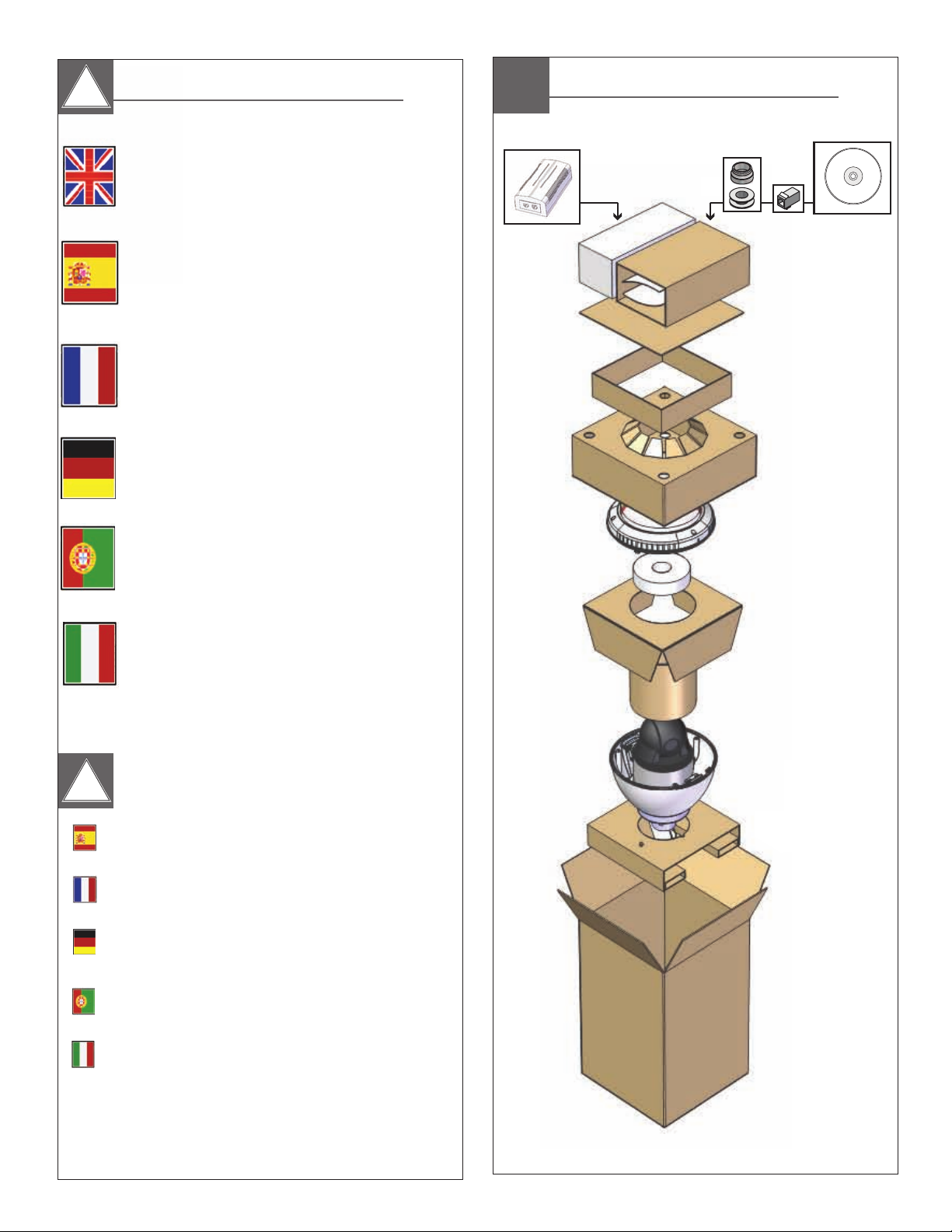
Contents of Box
CD
Electrical Specifications
!!
Power POE 56V
UNI-ONER/EP
English
Español
Français
Deutsch
Portuguese
Input Power: 100 to 240Vac (Midspan)
Power: 1.3A
Frequency: 50 to 60 HZ output
Camera: POE (56Vdc)
Heater: 56Vdc (max. 40W)
Energía de entrada: 100 a 240Vac (Midspan)
Energía: 1.3A
Frecuencia: 50 a 60 hertzios de salida
Cámara: POE (56Vdc)
Calentador: 56Vdc (máximo 40W)
Puissance d'entrée: 100 à 240Vac (Midspan)
Puissance: 1.3A
Fréquence: 50 à 60 hertz de rendement
Appareil-photo: POE (56Vdc)
Réchauffeur: 56Vdc (maximum 40W)
Zugeführte Energie: 100 zu 240Vac (Midspan)
Energie: 1.3A
Frequenz: 50 bis 60 Hz Ausgang
Kamera: POE (56Vdc)
Heizung: 56Vdc (Maximum 40W)
Poder de entrada: 100 a 240Vac (Midspan)
Poder: 1.3A
Freqüência: 50 a 60 hertz de saída
Câmera: Ponto de entrada (56Vdc)
Calefator: 56Vdc (máximo 40W)
Italiano
!!
Español
Français
Deutsch
Portuguese
Italiano
Alimentazione in ingresso di entrata: 100 a 240Vac (Midspan)
Potere: 1.3A
Frequenza: 50 - 60 hertz di uscita
Macchina fotograca: POE (56Vdc)
Riscaldatore: 56Vdc (massimo 40W)
The maximum distance between the network switch and the
camera enclosure should not exceed 100m - use Cat 5e or
Cat 6 cable only.
La distancia máxima entre el conmutador de red y el carcasa
de la cámara no debe superar los 100 - Cat5e uso o
Cat6 solamente.
La distance maximale entre le commutateur de réseau et le
boîtier de la caméra ne doit pas dépasser 100m - Cat5e
utilisation ou Cat6 seul câble.
Der maximale Abstand zwischen der Netzwerk-Switch und die
Kamera-Gehäuse sollte nicht mehr als 100m - Verwendung
Cat5e oder Cat6 Kabel nur.
A distância máxima entre o interruptor da rede ea caixa da
câmara não deve exceder 100m - Cat5e utilização ou
Cat6 cabo apenas.
La distanza massima tra l'interruttore e la rete alloggiamento
della telecamera non deve superare i 100m - Cat5e uso o
Cat6 cavo.
• Contact customer service for a full list of compatible Axis cameras.
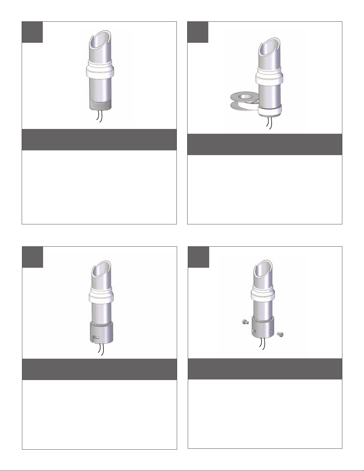
Mounting Preparation
1
Securely attach pendant pipe or the UNI-WMB1
(See block 9 when using UNI-WMB3). Pull wiring
through pipe and position grommet as shown.
• Con seguridad pipa pendiente de la fijación o el UNI-WMB1 (véase el bloque 9
para UNI-WMB3). Tire del cableado a través de la pipa y del ojal de la posición
como se muestra.
• Solidement pipe pendante d'attache ou l'UNI-WMB1 (voir le bloc 9 pour
UNI-WMB3). Tirez le câblage par la pipe et le canon isolant de position comme
montré.
• Sicher hängendes Rohr der Befestigungs oder das UNI-WMB1 (sehen Sie Block
9 für UNI-WMB3). Ziehen Sie Verdrahtung durch Rohr und Positionsgummimuffe
wie gezeigt.
• Firmemente tubulação do pendente do anexo ou o UNI-WMB1 (veja o bloco 9
para UNI-WMB3). Puxe a fiação através da tubulação e do ilhó da posição como
mostrado.
• Saldamente tubo del pendente dell'attaccatura o il UNI-WMB1 (vedi il blocco 9
per UNI-WMB3). Tiri i collegamenti tramite il tubo ed il gommino di protezione di
posizione come indicato.
2
Wrap Teflon tape around the pipe threads
to ensure a tight seal.
• La cinta del Teflon del abrigo alrededor de la pipa rosca
para asegurar un sello apretado.
• La bande de teflon d'enveloppe autour de la pipe filète
pour assurer un joint serré.
• Verpackung Teflonklebeband um das Rohr verlegt, um eine
feste Dichtung sicherzustellen.
• A fita adesiva do Teflon do envoltório em torno da tubulação
enfía para assegurar um selo apertado.
• Il nastro del Teflon dell'involucro intorno al tubo filetta per
accertare una guarnizione stretta.
TM
3
Screw the coupling onto the pipe threads
until it is hand tight.
• Atornille el acoplador sobre los hilos de rosca de la pipa
hasta que es mano firmemente.
• Vissez le couplage sur les fils de pipe jusqu'à ce que ce
soit main fortement.
• Schrauben Sie die Koppelung auf die Rohrgewinde, bis es
Hand fest ist.
• Parafuse o acoplamento nas linhas da tubulação até que
esteja mão firmemente.
• Avviti l'accoppiamento sui filetti del tubo fino a che non sia
fortemente mano.
4
Screw the (2) bolts into the coupling.
• Atornille (2) los pernos en el acoplador.
• Vissez (2) les boulons dans l'accouplement.
• Schrauben Sie die (2) Schraubbolzen in die Koppelung.
• Parafuse (2) os parafusos no acoplamento.
• Avviti (2) i bulloni nell'accoppiamento.

Loop the lanyard over the set screw to
temporarily hold housing.
• Loop el cordón sobre el tornillo de fijación para mantener
temporalmente de la vivienda.
• Boucle de la longe sur la vis de réglage pour détenir
temporairement des logements.
• Loop das Trageband über die Stellschraube, um
vorübergehend halten Gehäuse.
• Loop o colhedor sobre o parafuso para prender
temporariamente habitação.
• Loop il cordino sulla vite di tenere temporaneamente alloggi.
5
6
Complete wiring by connecting the
RJ45 cable.
• Completar cableado conectando el Cable RJ45.
• Terminer le câblage en connectant l' Un câble RJ45.
• Komplette Verkabelung, indem Sie das RJ45-Kabel.
• Conclua a fiação ligando o cabo RJ45.
7
Undo the lanyard, pull housing up and twist
secure with the locking bolt and washers.
• Deshaga el acollador, tire de contener para arriba y tuerza seguro
con el perno y las arandelas de fijación.
• Défaites la lanière, tirez loger vers le haut et tordez bloqué avec le
boulon et les rondelles de fermeture.
• Annulieren Sie die Abzuglinie, ziehen Sie oben unterbringen und
verdrehen Sie sicheres mit dem verriegelnschraubbolzen und den
Unterlegscheiben.
• Undo o colhedor, puxe abrigar acima e torça seguro com o
parafuso e as arruelas travando.
• Undo la cordicella, tiri l'alloggio in su e torca sicuro con il bullone e
le rondelle di bloccaggio.
• Completare il cablaggio collegando il cavo RJ45.
8
Slide the grommet down over the coupling to
prevent water from entering and complete the
assembly. Go to block 18.
• Resbale el ojal abajo sobre el acoplador para evitar que el agua
entre y para terminar a la asamblea.
• Glissez le canon isolant vers le bas au-dessus de l'accouplement
pour empêcher l'eau d'entrer et pour accomplir l'assemblée.
• Schieben Sie die Gummimuffe unten über der Koppelung, um zu
verhindern, daß Wasser und die Versammlung durchzuführen
hereinkommt.
• Deslize o ilhó para baixo sobre o acoplamento para impedir que a
água entre e para terminar o conjunto.
• Faccia scorrere il gommino di protezione giù sopra l'accoppiamento
per impedire l'acqua entrare e per completare il complessivo.

UNI-WMB3
9
Install the wall mount bracket to a wall or
adapter bracket.
• Instale el soporte del montaje de la pared a la pared o soporte
del adaptador.
• Installez la parenthèse de bâti de mur sur le mur ou parenthèse
d'adapteur.
• Bringen Sie den Wandeinfassungshaltewinkel zur Wand an oder
Adapterhaltewinkel.
• Instale o suporte da montagem da parede à parede ou suporte
do adaptador.
• Installi la staffa del supporto della parete alla parete o staffa
dell'adattatore.
10
If using external ¾” (27mm) conduit attach
appropriate hardware.
• Si usa conducto del ¾ (27mm) externo el” ata apropiado
hardware.
• Si conduit employant ¾ (27mm) externe le » attachent approprié
matériel.
• Wenn es externes verwendet, ¾“ (27mm) bringen Rohr passendes
an Hardware.
• Se usando canalização do ¾ (27mm) externo a” une apropriado
ferragem.
• Se usando il condotto del ¾ (27mm) esterno„ attacca adatto
fissaggi.
11
Housing coupling
Gasket
Remove housing coupling and gasket.
• Quite el acoplador y la junta de la cubierta.
• Enlevez l'accouplement et la garniture de logement.
• Entfernen Sie Gehäusekoppelung und -dichtung.
• Remova o acoplamento e a gaxeta da carcaça.
• Rimuova l'accoppiamento e la guarnizione dell'alloggiamento.
12
Attach safety lanyard to eyebolt.
• Ate el acollador de la seguridad al perno de argolla.
• Attachez la lanière de sûreté à l'oeil à queue filetée.
• Bringen Sie Sicherheitsabzuglinie zum Ringbolzen an.
• Una o colhedor da segurança ao parafuso tensor.
• Attacchi la cordicella di sicurezza al bullone a occhio.

UNI-WMB3 Continued
13
Feed wiring into wall mount,
complete connections.
• Cableado de la alimentación en el montaje de la pared,
conexiones completas.
• Câblage d'alimentation dans le bâti de mur, raccordements
complets.
• Zufuhrverdrahtung in Wandeinfassung, komplette Anschlüsse.
• Fiação da alimentação na montagem da parede, conexões
completas.
• Collegamenti dell'alimentazione nel supporto della parete,
collegamenti completi.
14
UNDO lanyard and connect housing to wall
mount coupling.
• DESHAGA el acollador y conecte la cubierta con el acoplador
del montaje de la pared.
• DÉFAITES la lanière et reliez le logement à l'accouplement de
bâti de mur.
• ANNULIEREN Sie Abzuglinie und schließen Sie Gehäuse an
Wandeinfassungskoppelung an.
• UNDO o colhedor e conecte a carcaça ao acoplamento da
montagem da parede.
• DISFACCIA la cordicella e colleghi l'alloggiamento
all'accoppiamento del supporto della parete.
15
Attach safety hardware.
• Ate el hardware de la seguridad.
• Attachez le matériel de sûreté.
• Bringen Sie Sicherheits-Hardware an.
• Una a ferragem da segurança.
• Attacchi i fissaggi di sicurezza.
16
Install the upper cover to the main
wall mount body.
• Instale la cubierta superior al cuerpo del montaje de la
pared principal.
• Installez la couverture supérieure sur le corps de bâti de
mur principal.
• Bringen Sie die obere Abdeckung zum Hauptwand-
Einfassungskörper an.
• Instale a tampa superior ao corpo da montagem da
parede principal.
• Installi la copertura superiore al corpo del supporto della
parete principale.

17
18
Secure the bolts with the provided
Allen wrench.
• Asegure los pernos con la llave Allen proporcionada.
• Fixez les boulons avec la clé Allen Fournie.
• Sichern Sie die Schraubbolzen mit dem zur Verfügung
gestellten Inbusschlüssel.
• Fixe os parafusos com a chave de Allen fornecida.
• Assicuri i bulloni con la chiave di Allen fornita.
CALIBRATION BUTTON
FAN
LED
Internal view, note the location of the
calibration button.
• Vista interior, tenga en cuenta la ubicación del
botón de calibración.
• Vue de l'intérieur, notez l'emplacement du bouton
de calibrage.
• Innenansicht, notieren Sie den Speicherort der
Kalibrierung Taste.
• Vista interna, observe a localização do botão de
calibração.
• Vista interna, notare la posizione del pulsante di
calibrazione.
FAN
Calibrating
19
RED button
To calibrate the unit first turn the power on.
The camera and fans will then turn on.
• Para calibrar la primera unidad de encender la cámara.
La cámara y los aficionados a continuación se encenderá.
• Pour étalonner la première unité allumer l'appareil. La
caméra et les amateurs pourront alors mettre en marche.
• Um das Gerät zu kalibrieren, zuerst den Strom auf. Die
Kamera und die Fans werden dann wieder einzuschalten.
• Para calibrar a primeira unidade ligar a energia. A câmera
e os fãs vão ligue.
• Per calibrare la prima unità accendere l'apparecchio.
La fotocamera e gli appassionati poi accende.
20
RED button
(restore settings)
Press and hold the calibration button for 1 sec. - LED
light will turn on to confirm start of calibration, LED will
turn off when complete.
• Mantenga pulsado el botón de calibración de 1 seg. - La luz LED se
encenderá para confirmar inicio de la calibración, el LED se apagará
cuando haya terminado.
• Appuyez et maintenez enfoncé le bouton d'étalonnage pour 1 sec.
- La lumière LED s'allume pour confirmer début de l'étalonnage, la DEL
s'éteint lorsque vous avez terminé.
• Halten Sie die Taste Kalibrierung für 1 sek. - LED-Licht schaltet sich ein, um
Start der Kalibrierung zu bestätigen, werden LED auszuschalten, wenn
abgeschlossen ist.
• Pressione e segure o botão de calibração por 1 segundo. - Luz LED acenderá
para confirmar início de calibragem, LED desliga quando terminar.
• Premere e tenere premuto il pulsante di calibrazione per 1 sec. - LED si
accende per confermare la partenza della calibrazione, il LED si spegnerà
una volta completato.

21
22
Before
Tab
After
Loop the lanyard around the tab inside
the housing.
• Coloque el acollador alrededor de la lengüeta
dentro de la cubierta.
• Faites une boucle la lanière autour de l'étiquette
à l'intérieur du logement.
• Schlingen Sie die Abzuglinie um den Vorsprung
innerhalb des Gehäuses.
• Dê laços no colhedor em torno da aba dentro
da carcaça.
• Colleghi la cordicella in circuito intorno alla linguetta
all'interno dell'alloggiamento.
23
Align the arrows on the outside of the
dome and lock.
• Alinee las flechas en el exterior de la bóveda y trábese.
• Alignez les flèches sur l'extérieur du dôme et fermez à
clef.
• Richten Sie die Pfeile auf der Außenseite der Haube
aus und verriegeln Sie sich.
• Alinhe as setas na parte externa da abóbada e
trave-as.
• Allinei le frecce sulla parte esterna della cupola
e blocchi.
24
Fasten down the dome with a Phillips
screwdriver.
• Sujete abajo de la bóveda con un destornillador
Phillips.
• Attachez en bas du dôme avec un tournevis Phillips.
• Befestigen Sie sich hinunter die Haube mit einem
Kreuzkopfschraubenzieher.
• Prenda abaixo a abóbada com uma chave de
fenda Phillips.
• Fissisi giù la cupola con un cacciavite "phillips".
Wipe the dome clean. Please follow the
proper cleaning procedure as shown.
• Limpie la cúpula limpio. Por favor, siga el procedimiento
de limpieza adecuado, como se muestra.
• Essuyez le dôme propre. S'il vous plaît suivre la procédure
de nettoyage, comme indiqué dans.
• Wischen Sie die Kuppel reinigen. Bitte beachten Sie die
ordnungsgemäße Reinigung Verfahren wie.
• Limpe a cúpula limpo. Por favor, siga o procedimento
adequado de limpeza conforme indicado.
• Pulire la cupola pulito. Si prega di seguire la corretta
procedura di pulizia, come indicato.

How - to Clean a Dome Bubble
To effectively clean your video surveillance dome bubble (acrylic or
polycarbonate) from debris, follow these simple step-by-step instructions.
Materials Needed
• Clean, dry, pressurized air
• Water
• High quality soft paper towel
• Isopropyl alcohol (rubbing alcohol)
• Scratch-resistant cloth
Cleaning Dome Exterior
1. When cleaning exterior of dome, make sure bubble is con
securely to the camera housing.
2. While utilizing a nonabrasive cloth and cleaning agent, safe for use
on acrylic or polycarbonate plastic, in a spiral motion, gently clean
exterior of bubble.
3. Dry immediately with dry, pressurized air to prevent water spots.
Cleaning Dome Interior
1. Safely remove the dome bubble from the camera housing. To
prevent scratches or additional imperfections, utilize a scra
esistant cloth when handling the bubble.
r
2. Once removed, carefully place the bubble on a clean surface, safe
from dust and any other foreign debris. Do not place the bubble
face down on its curved surface.
3. While holding onto the bubble, use clean, dry, pressurized air to
gently blow off all loose particles. For more thorough cleaning, try
one of the following:
nected
tch-
i. Rinse bubble with water an
pressurized air to prevent water spots
ii. Roll a section of high-quality paper towel into a tube,
and tear tube in half. Wet torn edge with rubbing
alcohol solution (75% alcohol & 25% water). While
holding the bubble facing downward, wipe the interior
with the paper towel tube in a circular motion from the
outside – in. Use spiraling motions when cleaning.
Repeat abo
steps to clean entire bubble.
ve
d immediately dry with

Replacement Parts List
Part Number Description
1 SDO180W PENDENT COUPLING (WHITE)
2 RPFD2612 HOUSING TOP GASKET
3 RPFD709 HOUSING TOP
4 RP70VL2008 POE POWER PCB
5 RPFD702 24VAC HEATER
6 RPFD060 CAMERA BRACKET
7 RPPKH6063 SPACERS
8 RPFDO80 12VDC BLOWER
9 RPLEDR02 LED
10 RP70SW07 CALIBRATION SWITCH
11 RPVL4138 PLASTIC CAP
12 RPVL4101 QUICK RELEASE BRACKET
13 N/A CAMERA
14 RPFD703 CLAMPING RING
15 RP96GK2558 DOME GASKET
16a RPFD7C CLEAR DOME
16b RPFD7T TINTED DOME
17 RPFD701 TRIM RING
N/S RPPKE1110 ELECTRICAL PACKET
1
2
3
4
5
7
6
8
12
13
11
10
9
14
15
16
17
RED button
(restore settings)
To restore the software to its original factory default
settings, press and hold the RED button for 5 or more
seconds. Re-calibration should only be required if you
signicantly charge the camera system.
EXAMPLES INCLUDE:
1. Move dome to another location
2. Replace ER_EP camera
3. Upgrade the system wiring or connectors
To Re-calibrate the Enclosure:

Available Mounting Accessories
UNI-WMB1
Gooseneck
Wall Mount
UNI-WMB1
UNI-WMB3
Wall Mount
Bracket
Wall Mount
Mounting Accessories Needed:
• UNI-WMB1 - Gooseneck Wall Mount
• Outdoor Pendant Housing
UNI-RMB1
RoofMount (Parapet)
Mounting Accessories Needed:
• UNI-RMB1 - Aluminum Parapet Mount
• Outdoor Pendant Housing
UNI-RMB1
Aluminum
Parapet Mount
UNI-CMA1
Aluminum Corner
Mount Adaptor
UNI-WMB3
UNI-PMA1
Aluminum Existing
Pole Mount Adaptor
Wall Mount Bracket
Mounting Accessories Needed:
• UNI-WMB3 - Wall Mount
• Outdoor Pendant Housing
UNI-CMA1
Corner Mount
Mounting Accessories Needed:
• UNI-CMA1 - Aluminum Corner Mount Adaptor
• UNI-WMB3 - Gooseneck Wall Mount
• Outdoor Pendant Housing
UNI-WMBB1
Pole / Wall Mount
UNI-PMA1
Pole Mount
Mounting Accessories Needed:
• UNI-WMB1or UNI-WMB3 - Gooseneck
Wall Mount
• UNI-PMA1 - Aluminum Exising Pole
Mount Adaptor
• Outdoor Pendant Housing
UNI-WMBB1
Pole/Wall Mount
Mounting Accessories Needed:
• UNI-WMB1or UNI-WMB3 - Gooseneck
Wall Mount
• UNI-WMBB1 - Pole / Wall Mount
• Outdoor Pendant Housing

Please note that to achieve the increased depth with the aspheric design for optimal camera lens to
capsule orientation, the capsule is slightly angled around the highest section. This creates a ”line’, visible to
the naked eye, around the upper most section of the capsule. This “line” serves as the geometric center line
used to insure proper camera placement. It is not typically seen by the camera. However, Sony RZ series
PTZ cameras are able to tilt up above the horizon to 25°, this wide range of tilt motion at a wide angle view
may cause this line to be captured in the image.
Warranty
Note:
For warranty information on this and other Sony Security Systems Products, please visit:
http://pro.sony.com/bbsccms/services/files/servicesprograms/SecurityWarranty.pdf
 Loading...