

Sony DCR-TRV738E, DCR-TRV740, TRV740E, TRV840 Service Manual
SERVICE MANUAL
LEVEL 2
Link
SERVICE NOTE
DISASSEMBLY
BLOCK DIAGRAMS
FRAME SCHEMATIC DIAGRAMS
SCHEMATIC DIAGRAMS
PRINTED WIRING BOARDS
ADJUSTMENTS
REPAIR PARTS LIST
SPECIFICATIONS
SERVICE NOTE
DISASSEMBLY
BLOCK DIAGRAMS
FRAME SCHEMATIC DIAGRAMS
SCHEMATIC DIAGRAMS
PRINTED WIRING BOARDS
ADJUSTMENTS
REPAIR PARTS LIST
SPECIFICATIONS
Link
Revision History
Revision History
Ver 1.0 2002. 03
On the VC-278 board
This service manual provides the information that is premised the circuit board replacement service and not intended repair
inside the VC-278 board.
Therefore, schematic diagram, printed wiring board, waveforms, mounted parts location and electrical parts list of the VC-278
board are not shown.
The following pages are not shown.
Schematic diagram .............................Pages 4-23 to 4-72
Printed wiring board............................Pages 4-87 to 4-90
Waveforms ...........................................
Pages 4-93 to 4-95
Mounted parts location .............................
Pages 4-97 to 4-98
Electrical parts list................................... Pages 6-17 to 6-25
DCR-TRV738E/TRV740/
TRV740E/TRV840
RMT-814
US Model
Canadian Model
DCR-TRV740/TRV840
AEP Model
DCR-TRV738E/TRV740E
Australian Model
Hong Kong Model
Chinese Model
East European Model
North European Model
Russian Model
DCR-TRV740E
E Model
DCR-TRV740/TRV740E/TRV840
Korea Model
DCR-TRV740
Tourist Model
DCR-TRV740/TRV740E
Argentina Model
DCR-TRV840
M2000 MECHANISM
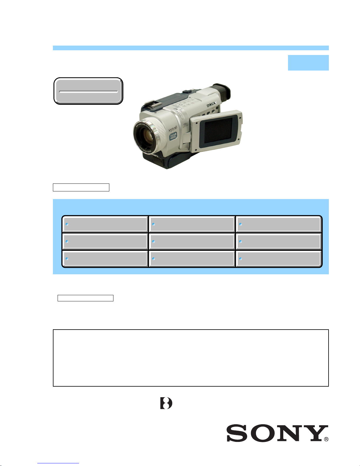
DIGITAL VIDEO CAMERA RECORDER
• For INSTRUCTION MANUAL, refer to separate file (992993871.pdf).
• For MECHANISM ADJUSTMENTS, refer to the “8mm Video MECHANICAL ADJUSTMENT MANUAL
IX
M2000 MECHANISM ” (9-929-861-11).
• The DCR-TRV740E uses two types of 2.5 inch LCD. For identification of the 2.5 inch LCD, see “SECTION 5.
1-5-1. LCD Type Check”.
• The DCR-TRV840 uses two types of the type SO or type CA LCD. For identification of the type SO or type CA
LCD, see “SECTION 5. 1-5-1. LCD Type Check”.
Photo : DCR-TRV740E

— 2 —
DCR-TRV738E/TRV740/TRV740E/TRV840
SPECIFICATIONS
COVER
COVER
Memory mode:
40 - 600 mm (1 5/8 - 23 5/8 in.)
Color temperature
Auto
Minimum illumination
7 lx (lux) (F1.6)
0 lx (lux) (in the NightShot mode)*
* Objects unable to be seen due to
the dark can be shot with
infrared lighting.
Input/output
connectors
S video input/output
S video output
4-pin mini DIN
Luminance signal: 1 Vp-p,
75 Ω (ohms), unbalanced
Chrominance signal: 0.286 Vp-p,
75 Ω (ohms), unbalanced
Chrominance signal: 0.3 Vp-p,
75 Ω (ohms), unbalanced
Audio/Video input/output
Audio/Video output
AV MINIJACK, 1 Vp-p, 75 Ω
(ohms), unbalanced, sync negative
327 mV, (at output impedance
more than 47 kΩ (kilohms))
Output impedance with less than
2.2 kΩ (kilohms)/Stereo minijack
(ø 3.5 mm)
Input impedance more than 47 kΩ
(kilohms)
Headphone jack
Stereo minijack (ø 3.5 mm)
USB jack
mini-B
LANC jack
Stereo mini-minijack (ø 2.5 mm)
MIC jack
Stereo minijack (ø 3.5 mm)
DV input/output
4-pin connector
DV output
LCD screen
Picture
DCR-TRV738E/TRV740/TRV740E:
DCR-TRV738E:
DCR-TRV740/TRV740E/TRV840:
DCR-TRV738E/TRV740E:
DCR-TRV740/TRV740E/TRV840:
DCR-TRV740/TRV740E/TRV840:
DCR-TRV740/TRV840:
DCR-TRV738E:
DCR-TRV738E:
DCR-TRV740/TRV740E/TRV840:
6.2 cm (2.5 type)
50.3 × 37.4 mm (2 × 1 1/2 in.)
DCR-TRV840:
8.8 cm (3.5 type)
72.2 × 50.4 mm (2 7/8 × 2 in.)
Total dot number
For NTSC models and European
models:
For other countries models of
DCR-TRV740E:
61 600 (280 × 220)
123 200 (560 × 220)
Video camera
recorder
System
Video recording system
2 rotary heads
Helical scanning system
Audio recording system
Rotary heads, PCM system
Quantization: 12 bits (Fs 32 kHz,
stereo 1, stereo 2), 16 bits
(Fs 48 kHz, stereo)
Video signal
NTSC color, EIA standards
PAL colour, CCIR standards
Recommended cassette
Hi8/Digital8 video cassette
Recording/playback time
(using 90 min. Hi8 video cassette)
(using 120 min. Hi8 video cassette)
SP mode: 1 hour
LP mode: 1 hour and 30 minutes
Fast-forward/rewind time
(using 90 min. Hi8 video cassette)
(using 120 min. Hi8 video cassette)
Approx. 5 min.
Viewfinder
Electric Viewfinder, Monochrome
Image device
DCR-TRV740/TRV840:
DCR-TRV740/TRV840:
4.5 mm (1/4 type) CCD
(Charge Coupled Device)
Gross: Approx. 1 070 000 pixels
Effective: Approx. 690 000 pixels
(Camera mode)
Approx. 1 000 000 pixels
(Memory mode)
DCR-TRV738E:
DCR-TRV738E/TRV740E:
DCR-TRV740/TRV840:
DCR-TRV738E/TRV740E:
DCR-TRV740/TRV840:
DCR-TRV738E/TRV740E:
3.8 mm (1/4.7 type) CCD
(Charge Coupled Device)
Gross: Approx. 1 070 000 pixels
Effective: Approx. 690 000 pixels
(Camera mode)
Approx. 1 000 000 pixels
(Memory mode)
DCR-TRV740E:
3.8 mm (1/4.7 type) CCD
(Charge Coupled Device)
Gross: Approx. 1 070 000 pixels
Effective (still):
Effective (moving):
Approx. 1 000 000 pixels
Approx. 690 000 pixels
Lens
Combined power zoom lens
Filter diameter 37 mm (1 1/2 in.)
15× (Optical), 420×
(Digital)
Focal length
3.6 - 54 mm (5/32 - 2 1/4 in.)
When converted to a 35 mm still
camera
Camera mode:
48 - 720 mm (1 15/16 - 28 3/8 in.)
General
Power requirements
7.2 V (battery pack)
8.4 V (AC power adaptor)
Average power consumption
(when using the battery pack)
During camera recording using
LCD
DCR-TRV738E:
3.4 W
DCR-TRV740:
4.3 W
DCR-TRV840:
4.5 W
DCR-TRV740E:
4.2 W
Viewfinder
DCR-TRV740/TRV840:
3.5 W
DCR-TRV738E/TRV740E:
3.4 W
Operating temperature
0°C to 40°C (32°F to 104°F)
Recommended charging
temperature
10°C to 30°C (50°F to 86°F)
Storage temperature
–20°C to + 60°C (–4°F to + 140°F)
Dimensions (approx.)
207 × 101 × 85 mm
(8 1/4 × 4 × 3 3/8 in.)
Mass (approx.)
DCR-TRV738E/TRV740/TRV740E:
900 g (1 lb 15 oz)
DCR-TRV840:
930 g (2 lb)
excluding the battery pack,
cassette, lens cap and shoulder
strap
DCR-TRV738E/TRV740/TRV740E:
1 040 g (2 lb 4 oz)
DCR-TRV840:
1 070 g (2 lb 5 oz)
including the battery pack
(NP-FM50), 120min. Hi8 cassette
(DCR-TRV740/TRV840), 90min.
Hi8 cassette (DCR-TRV738E/TRV740E),
lens cap and shoulder strap
Supplied accessories
See page 4.
AC power adaptor
Power requirements
100 – 240 V AC, 50/60 Hz
Power consumption
23 W
Output voltage
DC OUT: 8.4 V, 1.5 A in the
operating mode
Operating temperature
0°C to 40°C (32°F to 104°F)
Storage temperature
–20°C to + 60°C (–4°F to + 140°F)
Dimensions (approx.)
125 × 39 × 62 mm
(5 × 1 9/16 × 2 1/2 in. ) (w/h/d)
excluding projecting parts
Mass (approx.)
280 g (9.8 oz)
excluding power cord
Battery pack
Maximum output voltage
DC 8.4 V
Mean output voltage
DC 7.2 V
Capacity
8.5 wh (1 180 mAh)
Operating temperature
0°C to 40°C (32°F to 104°F)
Dimensions (approx.)
38.2 × 20.5 × 55.6 mm
(1 9/16 × 13/16 × 2 1/4 in.)
(w/h/d)
Mass (approx.)
76 g (2.7 oz)
Type
Lithium ion
“Memory Stick”
Memory
Flash memory
8MB: MSA-8A
Operating voltage
2.7 – 3.6 V
Power consumption
Approx. 45 mA in the operating
mode
Approx. 130 µA in the standby
mode
Dimensions (approx.)
50 × 2.8 × 21.5 mm
(2 × 1/8 × 7/8 in.) (w/h/d)
Mass (approx.)
4 g (0.14 oz)
Design and specifications are
subject to change without notice.
— 3 —
DCR-TRV738E/TRV740/TRV740E/TRV840
1. Check the area of your repair for unsoldered or poorly-soldered
connections. Check the entire board surface for solder splashes
and bridges.
2. Check the interboard wiring to ensure that no wires are
"pinched" or contact high-wattage resistors.
3. Look for unauthorized replacement parts, particularly
transistors, that were installed during a previous repair. Point
them out to the customer and recommend their replacement.
4. Look for parts which, through functioning, show obvious signs
of deterioration. Point them out to the customer and
recommend their replacement.
5. Check the B+ voltage to see it is at the values specified.
6. Flexible Circuit Board Repairing
• Keep the temperature of the soldering iron around 270˚C
during repairing.
• Do not touch the soldering iron on the same conductor of the
circuit board (within 3 times).
• Be careful not to apply force on the conductor when soldering
or unsoldering.
Unleaded solder
Boards requiring use of unleaded solder are printed with the leadfree mark (LF) indicating the solder contains no lead.
(Caution: Some printed circuit boards may not come printed with
the lead free mark due to their particular size.)
: LEAD FREE MARK
Unleaded solder has the following characteristics.
• Unleaded solder melts at a temperature about 40°C higher than
ordinary solder.
Ordinary soldering irons can be used but the iron tip has to be
applied to the solder joint for a slightly longer time.
Soldering irons using a temperature regulator should be set to
about 350°C.
Caution: The printed pattern (copper foil) may peel away if the
heated tip is applied for too long, so be careful!
• Strong viscosity
Unleaded solder is more viscous (sticky , less prone to flo w) than
ordinary solder so use caution not to let solder bridges occur such
as on IC pins, etc.
• Usable with ordinary solder
It is best to use only unleaded solder but unleaded solder may
also be added to ordinary solder.
SAFETY CHECK-OUT
After correcting the original service problem, perform the following
safety checks before releasing the set to the customer.
SAFETY-RELATED COMPONENT WARNING!!
COMPONENTS IDENTIFIED BY MARK 0 OR DOTTED LINE WITH
MARK 0 ON THE SCHEMATIC DIAGRAMS AND IN THE PARTS
LIST ARE CRITICAL TO SAFE OPERATION. REPLACE THESE
COMPONENTS WITH SONY PARTS WHOSE PART NUMBERS
APPEAR AS SHOWN IN THIS MANUAL OR IN SUPPLEMENTS
PUBLISHED BY SONY.
ATTENTION AU COMPOSANT AYANT RAPPORT
À LA SÉCURITÉ!
LES COMPOSANTS IDENTIFÉS PAR UNE MARQUE 0 SUR LES
DIAGRAMMES SCHÉMATIQUES ET LA LISTE DES PIÈCES SONT
CRITIQUES POUR LA SÉCURITÉ DE FONCTIONNEMENT. NE
REMPLACER CES COMPOSANTS QUE PAR DES PIÈSES SONY
DONT LES NUMÉROS SONT DONNÉS DANS CE MANUEL OU
DANS LES SUPPÉMENTS PUBLIÉS PAR SONY.
CAUTION :
Danger of explosion if battery is incorrectly replaced.
Replace only with the same or equivalent type.
— 4 —
DCR-TRV738E/TRV740/TRV740E/TRV840
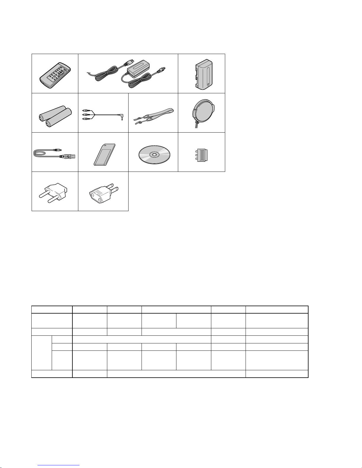
• SUPPLIED ACCESSORIES
Make sure that the following accessories are supplied with your camcorder .
• Abbreviation
CND : Canadian model
KR : Korea model
JE : Tourist model
AUS : Australian model
HK : Hong Kong model
CH : Chinese model
EE : East European model
NE : North European model
RU : Russian model
AR : Argentina model
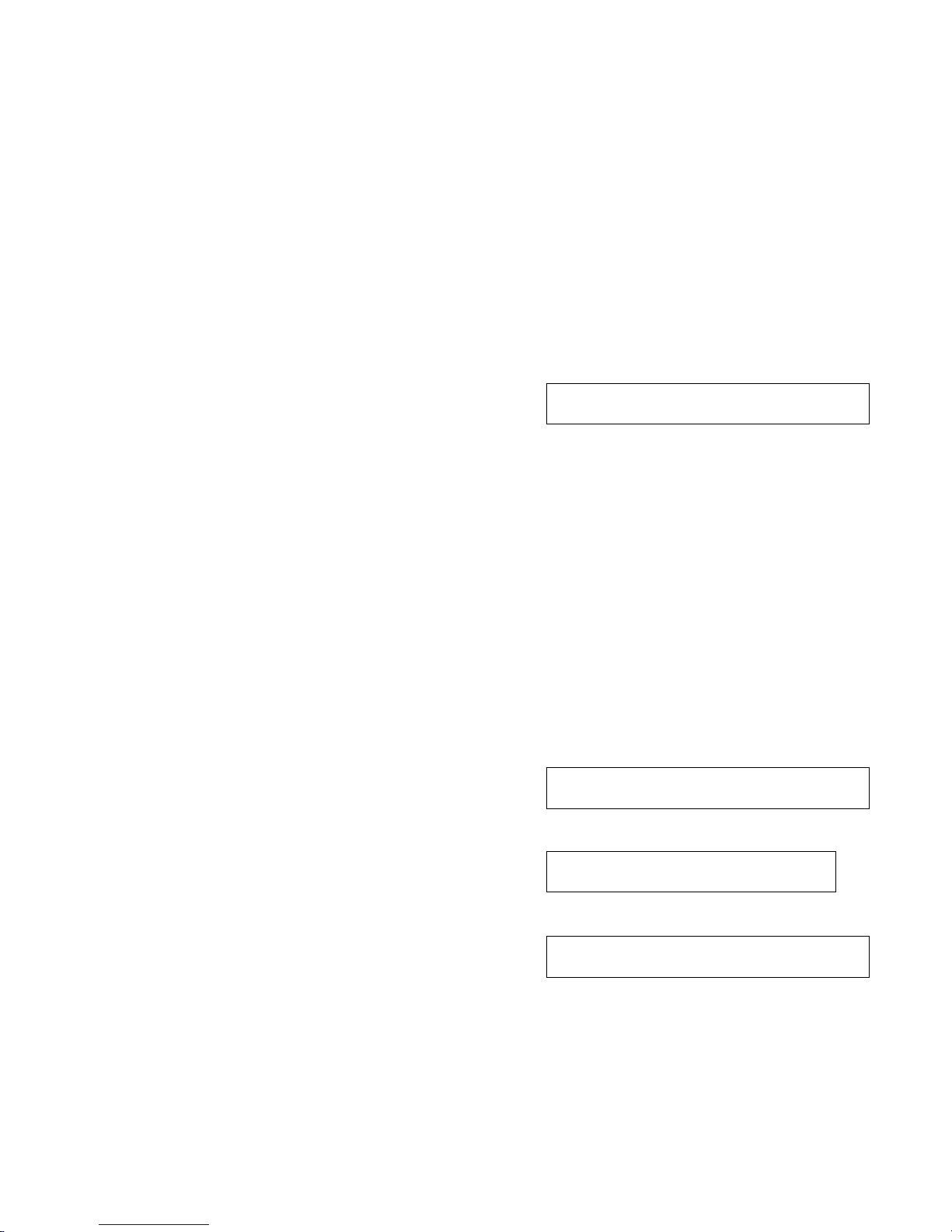
Table for difference of function
1 Wireless Remote Commander (1)
2 AC-L10A/L10B/L10C AC power
adaptor (1), Power cord (1)
3 NP-FM50 battery pack (1)
4 Size AA (R6) battery for Remote
Commander (2)
5 A/V connecting cable (1.5m)(1)
6 Shoulder strap (1)
7 Lens cap (1)
8 USB cable (1)
9 “Memory Stick” (1)
0 CD-ROM (USB Driver) (1)
SPVD (I) : US, CND models
SPVD : For other models
12 3
45 6
7
89 0
qs qd
qa
qa 21-pin adaptor (1)
(1)
(1)
For European models only
qs 2-pin conversion adaptor
DCR-TRV740: JE model/
DCR-TRV740E: JE model only
qd 2-pin conversion adaptor
DCR-TRV740: E/
TRV740E: E, HK models only
DCR-TRV740E
PAL
Model
Destination
Color System
size
pixel
LCD
type
VTR REC
DCR-TRV738E
AEP
PAL
123k
SH
✕
DCR-TRV740
US, CND, E,
KR, JE
NTSC
61k
SO
AEP, EE, NE,
RU
123κ
SH
E, AUS, HK,
JE, CH
61k
SO
DCR-TRV840
US, CND, E,
AR
NTSC
3.5 inch
123k
SO or CA
2.5 inch
a
Remark
type SH and CA:
with PD-156 board
type SO: with PD-160 board
a : with REC button
• The DCR-TRV740E uses two types of 2.5 inch LCD. For identification
of the 2.5 inch LCD, see “SECTION 5. 1-5-1. LCD Type Check”.
• The DCR-TRV840 uses two types of the type SO or type CA LCD. For
identification of the type SO or type CA LCD, see “SECTION 5. 1-5-1.
LCD Type Check”.
— 5 —
DCR-TRV738E/TRV740/TRV740E/TRV840
TABLE OF CONTENTS
1. SERVICE NOTE
1-1. SERVICE NOTE ·····························································1-1
1. POWER SUPPLY DURING REPAIRS ··························1-1
2. TO TAKE OUT A CASSETTE WHEN NOT EJECT
(FORCE EJECT) ····························································· 1-1
1-2. SELF-DIAGNOSIS FUNCTION····································1-2
1. Self-diagnosis Function ···················································1-2
2. Self-diagnosis Display·····················································1-2
3. Service Mode Display ·····················································1-2
3-1. Display Method ·······························································1-2
3-2. Switching of Backup No. ················································1-2
3-3. End of Display·································································1-2
4. Self-diagnosis Code Table ···············································1-3
2. DISASSEMBLY
2-1. 2.5 INCH LCD UNIT, PD-156/160 BOARD -1 ·············2-2
2-2. 2.5 INCH LCD UNIT, PD-156/160 BOARD -2 ·············2-3
2-3. 3.5 INCH LCD UNIT, PD-156/160 BOARD -1 ·············2-4
2-4. 3.5 INCH LCD UNIT, PD-156/160 BOARD -2 ·············2-4
2-5. BACK LIGHT ·································································2-5
2-6. FRONT PANEL SECTION·············································2-6
2-7. SI-032 BOARD ·······························································2-6
2-8. MICROPHONE·······························································2-7
2-9. CABINET (R) SECTION ···············································2-8
2-10. LENS SECTION ····························································· 2-9
2-11. CD-358 BOARD ····························································· 2-9
2-12. IRIS FLEXIBLE ASSEMBLY ······································2-10
2-13. EVF SECTION ······························································2-11
2-14. LB-076 BOARD -1 ·······················································2-11
2-15. LB-076 BOARD -2 ·······················································2-12
2-16. BATTERY PANEL SECTION ······································2-13
2-17. BATTERY TERMINAL BO ARD·································2-13
2-18. MEMORY STICK 10P CONNECTOR ························2-14
2-19. CONTROL SWITCH BLOCK (SS-1380) ····················2-14
2-20. CABINET (L) SECTION ·············································· 2-15
2-21. CS FRAME ASSEMBLY (25) ······································2-15
2-22. VC-278 BOARD ··························································· 2-16
2-23. MECHANISM DECK ··················································· 2-16
2-24. CONTROL SWITCH BLOCK (CF-2500) ···················2-19
2-25. CONTROL SWITCH BLOCK (FK-2500) ··················· 2-19
2-26. HINGE SECTION ·························································2-20
2-27. CIRCUIT BOARDS LOCATION·································2-21
2-28. FLEXIBLE BOARDS LOCATION ······························2-22
3. BLOCK DIAGRAMS
3-1. OVERALL BLOCK DIAGRAM (1/6) ···························3-1
3-2. OVERALL BLOCK DIAGRAM (2/6) ···························3-3
3-3. OVERALL BLOCK DIAGRAM (3/6) ···························3-5
3-4. OVERALL BLOCK DIAGRAM (4/6) ···························3-7
3-5. OVERALL BLOCK DIAGRAM (5/6) ···························3-9
3-6. OVERALL BLOCK DIAGRAM (6/6) ·························3-11
3-7. POWER BLOCK DIAGRAM (1/3) ······························ 3-13
3-8. POWER BLOCK DIAGRAM (2/3) ······························ 3-15
3-9. POWER BLOCK DIAGRAM (3/3) ······························ 3-17
4. PRINTED WIRING BOARDS AND
SCHEMATIC DIAGRAMS
4-1. FRAME SCHEMATIC DIAGRAM (1/2)·······················4-1
FRAME SCHEMATIC DIAGRAM (2/2)·······················4-3
4-2. SCHEMATIC DIAGRAMS
• CD-358 (CCD IMAGER)
SCHEMATIC DIAGRAM ······························ 4-7
• LB-076 (EVF, BACK LIGHT)
SCHEMATIC DIAGRAM ······························ 4-8
• SI-032 (STEADY SHOT, LASER LINK),
FP-411 FLEXIBLE
SCHEMATIC DIAGRAM ······························ 4-9
• CONTROL SWITCH BLOCK (CF-2500)
SCHEMATIC DIAGRAM ···························· 4-11
• PD-156 (1/2)(LCD DRIVER, BACKLIGHT)
SCHEMATIC DIAGRAM ···························· 4-13
• PD-156 (2/2)(DRIVER, TIMING GENERATOR)
SCHEMATIC DIAGRAM ···························· 4-15
• PD-160 (1/2)(CHA, DISPLAY DRIVE, BACK LIGHT)
SCHEMATIC DIAGRAM ···························· 4-17
• PD-160 (2/2)(LCD DRIVE, TG)
SCHEMATIC DIAGRAM ···························· 4-19
• LS-057 (S/T REEL SENSOR), FP-228 (DEW SENSOR),
FP-299 (MODE SWITCH), FP-300 (TAPE TOP),
FP-302 (TAPE END), FP-301 (TAPE LED) FLEXIBLE
SCHEMATIC DIAGRAMS··························4-21
• FP-410 FLEXIBLE,
CONTROL SWITCH BLOCK (SS-1380)
SCHEMATIC DIAGRAM ···························· 4-21
Shematic diagram of the VC-278 board are not shown.
Pages from 4-23 to 4-72 are not shown.
4-3. PRINTED WIRING BOARDS
• CD-358 (CCD IMAGER)
PRINTED WIRING BOARD ·······················4-73
• LB-076 (EVF, BACK LIGHT)
PRINTED WIRING BOARD ·······················4-74
• SI-032 (STEADY SHOT, LASER LINK)
PRINTED WIRING BOARD ·······················4-75
• FP-411 FLEXIBLE BOARD ·····································4-76
• LS-057 (S/T REEL SENSOR), FP-228 (DEW SENSOR),
FP-299 (MODE SWITCH), FP-300 (TAPE TOP),
FP-302 (TAPE END), FP-301 (TAPE LED)
FLEXIBLE BOARDS···································4-77
• FP-410 FLEXIBLE BOARD ·····································4-78
• PD-156 (LCD DRIVER, BACKLIGHT, DRIVER,
TIMING GENERATOR)
PRINTED WIRING BOARD ·······················4-79
• PD-160 (CHA, DISPLAY DRIVE, BACK LIGHT, LCD
DRIVE, TG)
PRINTED WIRING BOARD ·······················4-83
• FP-412 FLEXIBLE BOARD ·····································4-86
Printed wiring board of the VC-278 board are not shown.
Pages from 4-87 to 4-90 are not shown.
4-4. WAVEFORMS ······························································4-91
Waveforms of the VC-278 board are not shown.
Pages from 4-93 to 4-95 are not shown.
4-5. MOUNTED PARTS LOCATION ·································4-96
Mounted parts location of the VC-278 board is not shown.
Pages from 4-97 to 4-98 are not shown.
5. ADJUSTMENTS
1. Adjusting items when replacing main parts and boards ··5-2
5-1. CAMERA SECTION ADJUSTMENT ···························5-4
1-1. PREPARATIONS BEFORE ADJUSTMENT
(CAMERA SECTION) ···················································5-4
1-1-1.List of Service Tools························································5-4
1-1-2.Preparations ·····································································5-5
1-1-3.Precaution········································································5-7
1. Setting the Switch····························································5-7
2. Order of Adjustments ······················································5-7

— 6 —
DCR-TRV738E/TRV740/TRV740E/TRV840
3. Subjects ··········································································· 5-7
1-2. INITIALIZATION OF 8, A, B, C, D, E, F, 1B, 1C, 1E, 1F
PAGE DATA ···································································· 5-8
1-2-1.INITIALIZATION OF A, D PAGE DATA ······················5-9
1. Initializing the A, D Page Data ········································ 5-9
2. Modification of A, D Page Data ······································5-9
3. A Page Table····································································5-9
4. D Page Table··································································5-10
1-2-2.INITIALIZATION OF B, 1B PAGE DATA ·················· 5-11
1. Initializing the B, 1B Page Data ····································5-11
2. Modification of B, 1B Page Data ··································5-11
3. Loader writing inhibit mode setting ······························5-11
4. B Page Table ·································································· 5-11
5. 1B Page Table ································································ 5-11
1-2-3.INITIALIZATION OF 8, C, 1C PAGE DATA ·············· 5-12
1. Initializing the 8, C, 1C Page Data ································5-12
2. Modification of 8, C, 1C Page Data ······························5-12
3. 8 Page Table···································································5-13
4. C Page Table ·································································· 5-13
5. 1C Page Table ································································ 5-15
1-2-4.INITIALIZATION OF E, F, 1E, 1F PAGE DATA ········ 5-16
1. Initializing the E, F, 1E, 1F Page Data ·························· 5-16
2. Modification of E, F, 1E, 1F Page Data·························5-16
3. E Page Table ··································································5-17
4. F Page Table ·································································· 5-18
5. 1E Page Table ································································5-19
6. 1F Page Table ································································ 5-19
1-3. CAMERA SYSTEM ADJUSTMENTS ························5-20
1. HALL Adjustment ························································· 5-20
2. Flange Back Adjustment (Using Minipattern Box)·······5-21
3. Flange Back Adjustment (Using Flange Back Adjustment
Chart and Subject More Than 500m Away) ·················· 5-22
3-1. Flange Back Adjustment (1) ·········································· 5-22
3-2. Flange Back Adjustment (2) ·········································· 5-22
4. Flange Back Check························································5-23
5. Mechanical Shutter Adjustment ····································5-23
6. Black Defective CCD Adjustment·································5-24
7. Picture Frame Setting ····················································5-24
8. Color Reproduction Adjustment····································5-25
9. Auto White Balance & LV Standard Data Input ···········5-26
10. Auto White Balance Adjustment ···································5-27
11. White Balance Check ····················································5-28
12. Steady Shot Check·························································5-29
1-4. ELECTRONIC VIEWFINDER SYSTEM
ADJUSTMENT·····························································5-30
1. VCO Adjustment (VC-278 board) ································5-30
2. RGB AMP Adjustment (VC-278 board) ·······················5-31
3. Contrast Adjustment (VC-278 board) ···························5-31
1-5. LCD SYSTEM ADJUSTMENT ···································5-32
1-5-1.LCD Type Check ···························································5-32
1-5-2.LCD SYSTEM ADJUSTMENT (PD-156 board) ·········5-33
1. VCO Adjustment (PD-156 board)·································5-33
2. RGB AMP Adjustment (PD-156 board)························5-33
3. Contrast Adjustment (PD-156 board)····························5-34
4. COM AMP Adjustment (PD-156 board) ·······················5-34
5. V-COM Adjustment (PD-156 board) ····························5-35
6. White Balance Adjustment (PD-156 board)··················5-35
1-5-3.LCD SYSTEM ADJUSTMENT (PD-160 board) ·········5-36
1. VCO Adjustment (PD-160 board)·································5-36
2. PSIG Gray Adjustment (PD-160 board)························5-36
3. RGB AMP Adjustment (PD-160 board)························5-37
4. Black Limit Adjustment (PD-160 board) ······················5-37
5. Contrast Adjustment (PD-160 board)····························5-38
6. Center Level Adjustment (PD-160 board)·····················5-38
7. V-COM Adjustment (PD-160 board) ····························5-39
8. White Balance Adjustment (PD-160 board)··················5-39
5-2. MECHANISM SECTION ADJUSTMENT··················5-40
2-1. Hi8/STANDARD 8 MODE···········································5-40
2-1-1.OPERATING WITHOUT CASSETTE ························5-40
2-1-2.TAPE PATH ADJUSTMENT········································5-40
1. Preparations for Adjustment··········································5-40
2-2. DIGITAL8 MODE ························································ 5-41
2-2-1.HOW TO ENTER RECORD MODE WITHOUT
CASSETTE ···································································5-41
2-2-2.HOW TO ENTER PLAYBACK MODE WITHOUT
CASSETTE ···································································5-41
2-2-3.OVERALL TAPE PATH CHECK·································5-41
1. Recording of the tape path check signal························5-41
2. Tape path check ·····························································5-41
5-3. VIDEO SECTION ADJUSTMENT ······························5-42
3-1. PREPARATIONS BEFORE ADJUSTMENTS ············5-42
3-1-1.Equipment to Required··················································5-42
3-1-2.Precautions on Adjusting ···············································5-43
3-1-3.Adjusting Connectors ····················································5-44
3-1-4.Connecting the Equipment ············································ 5-44
3-1-5.Alignment Tape ·····························································5-45
3-1-6.Input/output Level and Impedance································5-46
3-2. SYSTEM CONTROL SYSTEM ADJUSTMENT········5-47
1. Initialization of 8, A, B, C, D, E, F, 1B, 1C, 1E, 1F Page
Data ···············································································5-47
2. Serial No. Input ·····························································5-47
2-1. Company ID Input·························································5-47
2-2. Serial No. Input ·····························································5-47
3-3. SERVO AND RF SYSTEM ADJUSTMENT ···············5-49
1. REEL FG Adjustment (VC-278 board)·························5-49
2. PLL f0 & LPF f0 Adjustment (VC-278 board) ··············5-49
3. Switching Position Adjustment (VC-278 board)···········5-50
4. AGC Center Level and APC & AEQ Adjustment ·········5-50
4-1. Preparations before adjustments····································5-50
4-2. AGC Center Level Adjustment (VC-278 board)···········5-50
4-3. APC & AEQ Adjustment (VC-278 board) ···················· 5-51
4-4. Processing after Completing Adjustments ····················5-51
5. PLL f
0 & LPF f0 Fine Adjustment (VC-278 board) ······5-52
6. Hi8/Standard8 Switching Position Adjustment
(VC-278 board) ·····························································5-52
7. CAP FG Duty Adjustment (VC-278 board)··················5-53
3-4. VIDEO SYSTEM ADJUSTMENTS·····························5-54
1. 54MHz/66MHz Origin Oscillation Adjustment
(VC-278 board) ·····························································5-54
2. S VIDEO OUT Y Level Adjustment (VC-278 board)···5-54
3. S VIDEO OUT Chroma Level Adjustment
(VC-278 board) ·····························································5-55
4. VIDEO OUT Y, Chroma Level Check (VC-278 board) 5-55
5. Hi8/Standard8 Y/C Output Level Setting
(VC-278 board) ·····························································5-56
6.
Hi8/standard 8mm AFC f0 Adjustment (VC-278 board) ·
5-56
3-5. AUDIO SYSTEM ADJUSTMENTS ····························5-57
1.
Hi8/Standard8 AFM BPF f0 Adjustment (VC-278 board)·
5-57
2. Hi8/Standard8 AFM 1.5 MHz Deviation Adjustment
(VC-278 board) ·····························································5-58
3. Hi8/Standard8 AFM 1.7 MHz Deviation Adjustment
(VC-278 board) ·····························································5-58
4. Digital8 Playback Level Check ·····································5-58
5. Overall Level Characteristics Check ·····························5-58
6. Overall Distortion Check···············································5-58
7. Overall Noise Level Check············································5-59
8. Overall Separation Check··············································5-59
5-4. SERVICE MODE ·························································· 5-60
4-1. ADJUSTMENT REMOTE COMMANDER················5-60
1. Using the Adjustment Remote Commander··················5-60
2. Precautions Upon Using the Adjustment Remote
Commander ···································································5-60
4-2. DATA PROCESS···························································5-61
4-3. SERVICE MODE ·························································· 5-62

— 7 —
DCR-TRV738E/TRV740/TRV740E/TRV840
1. Setting the Test Mode ····················································5-62
2. Emergence Memory Address ········································5-62
2-1. EMG Code (Emergency Code) ·····································5-62
2-2. MSW Code ···································································· 5-63
3. Bit V alue Discrimination ···············································5-64
4. Switch check (1) ···························································· 5-64
5. Switch check (2) ···························································· 5-64
6. Switch check (3) ···························································· 5-65
7. Switch check (4) ···························································· 5-65
8. Record of Use check (1) ················································ 5-65
9. Record of Use check (2) ················································ 5-66
10. Record of Self-diagnosis check ····································· 5-66
6. REPAIR PARTS LIST
6-1. EXPLODED VIEWS ······················································6-1
6-1-1.OVERALL SECTION·····················································6-1
6-1-2.CABINET (L) SECTION-1 ············································6-2
6-1-3.CABINET (L) SECTION-2 ············································6-3
6-1-4.LENS, EVF SECTION····················································6-4
6-1-5.CABINET (R) SECTION ···············································6-5
6-1-6.LCD SECTION (2.5 INCH LCD MODEL)
(TRV738E/TRV740/TRV740E) ······································6-6
6-1-7.LCD SECTION (3.5 INCH LCD MODEL) (TRV840) ··6-7
6-1-8.CASSETTE COMPARTMENT ASSY, DRUM ASSY ··· 6-8
6-1-9.LS CHASSIS BLOCK ASSEMBLY······························· 6-9
6-1-10.
MECHANICAL CHASSIS BLOCK ASSEMBLY-1 ··
6-10
6-1-11.
MECHANICAL CHASSIS BLOCK ASSEMBLY-2 ··
6-11
6-2. ELECTRICAL PARTS LIST ········································6-12
Parts list of the VC-278 board are not shown.
Pages from 6-17 to 6-25 are not shown.
* Color reproduction frame are shown on page 181.
1-1
SECTION 1
SERVICE NOTE
DCR-TRV738E/TRV740/TRV740E/TRV840
COVER
COVER
1-1. SERVICE NOTE
1. POWER SUPPLY DURING REPAIRS
In this unit, about 10 seconds after power is supplied (8.4V) to the battery terminal using the service power code (J-6082-223-A), the po wer
is shut off so that the unit cannot operate.
These following two methods are available to prevent this. Take note of which to use during repairs.
Method 1.
Use the DC IN terminal. (Use the AC power adaptor.)
Method 2.
Connect the adjustment remote commander RM-95 (J-6082-053-B) to the LANC jack, and set the HOLD switch to the “ADJ” side.
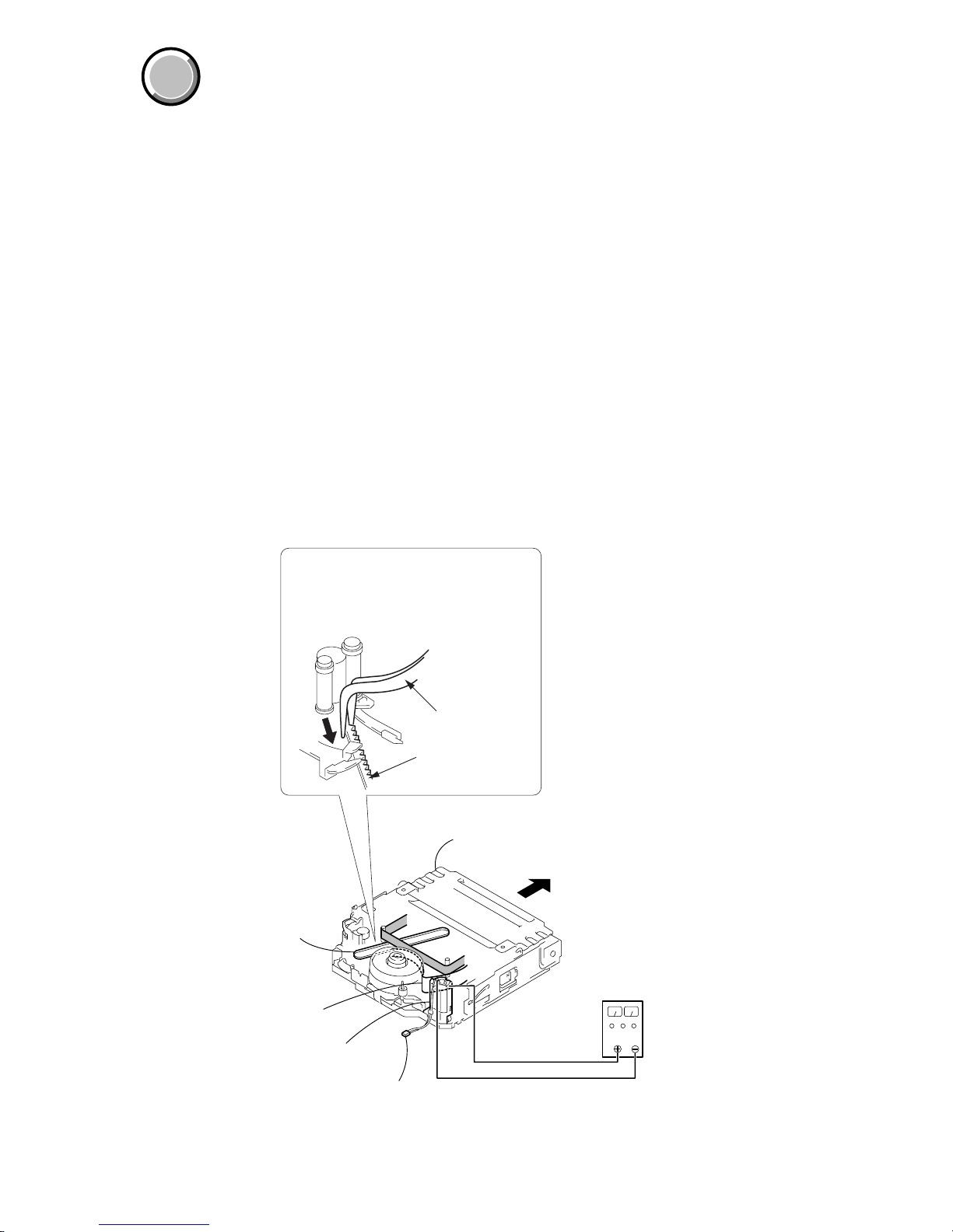
2. TO TAKE OUT A CASSETTE WHEN NOT EJECT (FORCE EJECT)
1 Refer to 2-6. to remove the front panel section.
2 Refer to 2-9. to remove the cabinet (upper) section.
3 Refer to 2-9. to remove the cabinet (R) section.
4 Refer to 2-10. to remove the lens section.
5 Refer to 2-13. to remove the EVF section.
6 Refer to 2-16. to remove the battery panel section.
7 Refer to 2-19. and 2-21. to remove the cabinet (L) section. (Include the CS frame assembly and control switch block (SS-1380).)
8 Disconnect CN4401 (2P) of VC-278 board.
9 Add +5V from the DC POWER SUPPLY and unload with a pressing the cassette compertment.
qa
Let your hold the cassette
compartment and rise the cassette
compartment to take out a cassette.
DC power supply
(+5V)
Loading
motor
Adjust the bending
of a tape
Timing belt
Press the cassette compartment not
to rise the cassette compartment
Disconnect CN4401 of
VC-278 board
0
Pull the timing belt in the direction of
arrow
A
with a pincette while pressing
the cassette compartment (take care
not to damage) to adjust the bending
of a tape.
Pincette
Timing belt
A
1-2
DCR-TRV738E/TRV740/TRV740E/TRV840
1-2. SELF-DIAGNOSIS FUNCTION
1. Self-diagnosis Function
When problems occur while the unit is operating, the self-diagnosis
function starts working, and displays on the viewfinder or Display
window what to do. This function consists of two display; selfdiagnosis display and service mode display.
Details of the self-diagnosis functions are provided in the Instruction
manual.
Note: The “self-diagnosis display” data will be kept even if lithium battery (CF-2500 block BT001 of cabinet (R) assemb ly) is
removed.
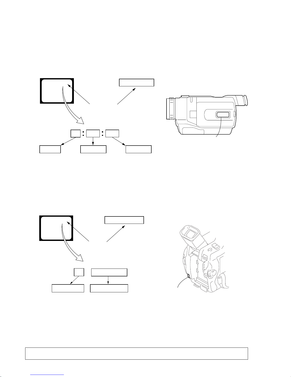
2. Self-diagnosis Display
When problems occur while the unit is operating, the counter of the
viewfinder or Display window shows a 4-digit display consisting
of an alphabet and numbers, which blinks at 3.2 Hz. This 5-character
display indicates the “repaired by:”, “block” in which the problem
occurred, and “detailed code” of the problem.
3. Service Mode Display
The service mode display shows up to six self-diagnosis codes shown in the past.
3-1. Display Method
While pressing the “STOP” key, set the switch from OFF to “VTR or PLAYER”, and continue pressing the “STOP” key for 5 seconds
continuously. The service mode will be displayed, and the counter will show the backup No. and the 5-character self-diagnosis codes.
3-2. Switching of Backup No.
By rotating the control dial, past self-diagnosis codes will be shown in order. The backup No. in the [] indicates the order in which the
problem occurred. (If the number of problems which occurred is less than 6, only the number of problems which occurred will be shown.)
[1] : Occurred first time [4] : Occurred fourth time
[2] : Occurred second time [5] : Occurred fifth time
[3] : Occurred third time [6] : Occurred the last time
3-3. End of Display
Turning OFF the power supply will end the service mode display.
Order of previous errors
Backup No.
Self-diagnosis Codes
C : 3 1 : 1 1
[3]
Lights up
Viewfinder
[3] C : 3 1 : 1 1
3 C : 3 1 : 11
Display window
1 1
3 1
C : 3 1 : 11
C
Repaired by:
Refer to page 1-3 and 1-4.
Self-diagnosis Code Table.
Indicates the appropriate
step to be taken.
E.g.
31 ....Reload the tape.
32 ....Turn on power again.
Block
Detailed Code
Blinks at 3.2Hz
C : Corrected by customer
H : Corrected by dealer
E : Corrected by service
engineer
Viewfinder Display window
C : 3 1 : 1 1
Display window
Control dial
1-3
DCR-TRV738E/TRV740/TRV740E/TRV840
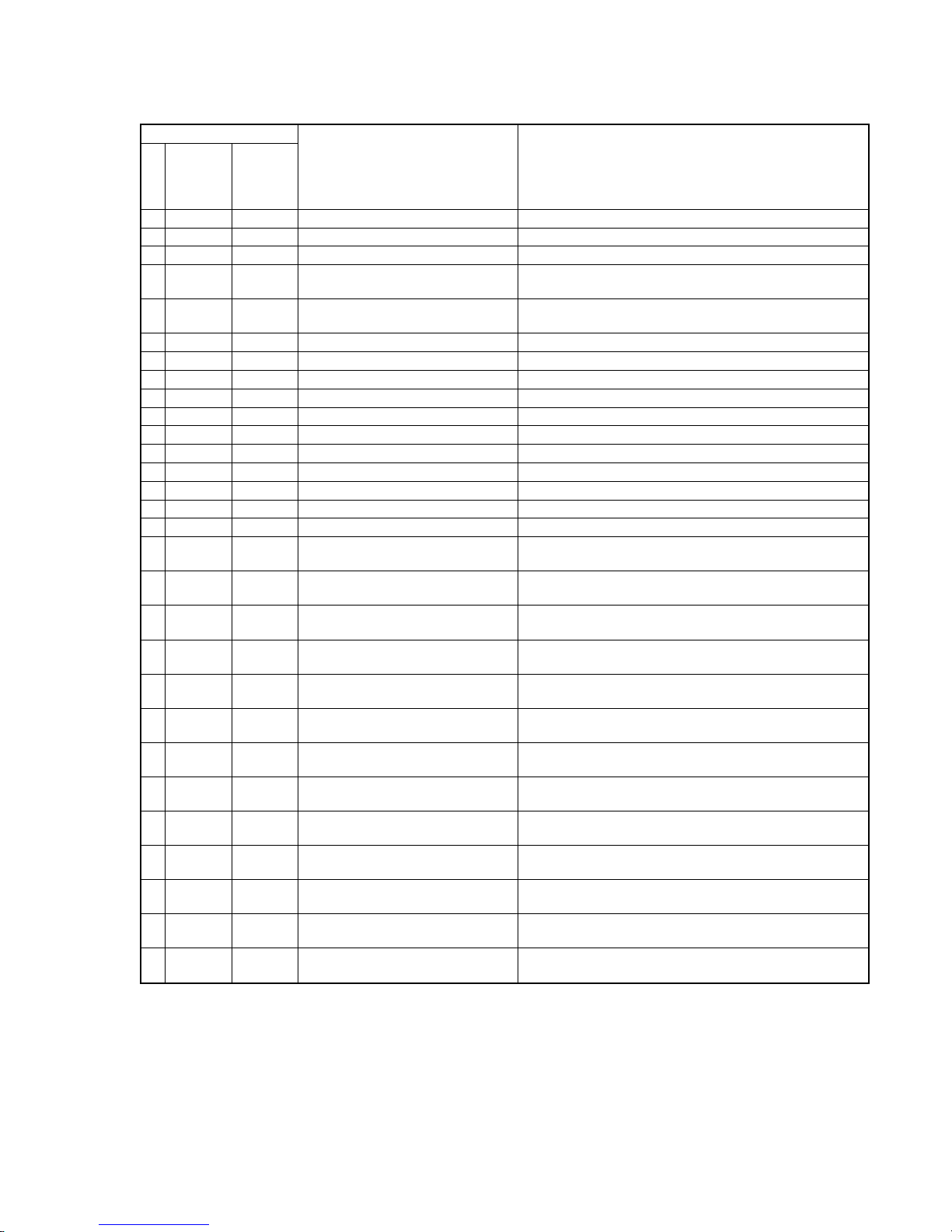
4. Self-diagnosis Code Table
C
C
C
C
C
C
C
C
C
C
C
C
C
C
C
C
C
C
C
C
C
C
C
C
C
C
C
C
C
Block
Function
04
21
22
31
31
31
31
31
31
31
31
31
31
31
31
31
32
32
32
32
32
32
32
32
32
32
32
32
32
Detailed
Code
00
00
00
10
11
20
21
22
23
30
31
40
41
42
43
44
10
11
20
21
22
23
30
31
40
41
42
43
44
Symptom/State
Non-standard battery is used.
Condensation.
Video head is dirty.
LOAD direction. Loading does not
complete within specified time
UNLOAD direction. Loading does not
complete within specified time
T reel side tape slacking when unloading
.
S reel
side tape slacking when unloading
.
T reel fault.
S reel fault.
FG fault when starting capstan.
FG fault during normal capstan operations.
FG fault when starting drum.
PG fault when starting drum.
FG fault during normal drum operations.
PG fault during normal drum operations.
Phase fault during normal drum operations.
LOAD direction loading motor time-
out.
UNLOAD direction loading motor
time-out.
T reel side tape slacking when
unloading.
S reel side tape slacking when
unloading.
T reel fault.
S reel fault.
FG fault when starting capstan.
FG fault during normal capstan
operations.
FG fault when starting drum.
PG fault when starting drum.
FG fault during normal drum
operations.
PG fault during normal drum
operations.
Phase fault during normal drum
operations.
Self-diagnosis Code
Repaired by:
Correction
Use the InfoLITHIUM battery.
Remove the cassette, and insert it again after one hour.
Clean with the optional cleaning cassette.
Load the tape again, and perform operations from the beginning.
Load the tape again, and perform operations from the beginning.
Load the tape again, and perform operations from the beginning.
Load the tape again, and perform operations from the beginning.
Load the tape again, and perform operations from the beginning.
Load the tape again, and perform operations from the beginning.
Load the tape again, and perform operations from the beginning.
Load the tape again, and perform operations from the beginning.
Load the tape again, and perform operations from the beginning.
Load the tape again, and perform operations from the beginning.
Load the tape again, and perform operations from the beginning.
Load the tape again, and perform operations from the beginning.
Load the tape again, and perform operations from the beginning.
Remove the battery or power cable, connect, and perform
operations from the beginning.
Remove the battery or power cable, connect, and perform
operations from the beginning.
Remove the battery or power cable, connect, and perform
operations from the beginning.
Remove the battery or power cable, connect, and perform
operations from the beginning.
Remove the battery or power cable, connect, and perform
operations from the beginning.
Remove the battery or power cable, connect, and perform
operations from the beginning.
Remove the battery or power cable, connect, and perform
operations from the beginning.
Remove the battery or power cable, connect, and perform
operations from the beginning.
Remove the battery or power cable, connect, and perform
operations from the beginning.
Remove the battery or power cable, connect, and perform
operations from the beginning.
Remove the battery or power cable, connect, and perform
operations from the beginning.
Remove the battery or power cable, connect, and perform
operations from the beginning.
Remove the battery or power cable, connect, and perform
operations from the beginning.
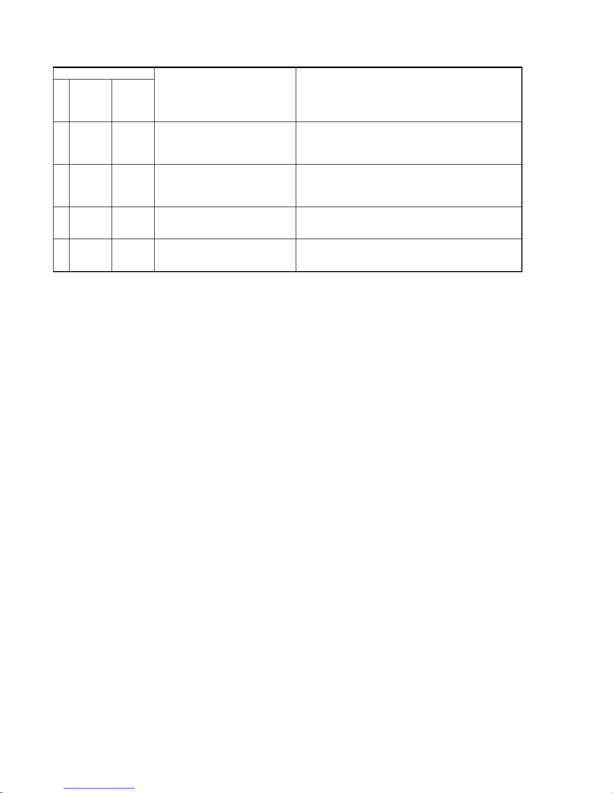
1-4E
DCR-TRV738E/TRV740/TRV740E/TRV840
E
E
E
E
Block
Function
61
61
62
62
Detailed
Code
00
10
00
01
Symptom/State
Difficult to adjust focus
(Cannot initialize focus.)
Zoom operations fault
(Cannot initialize zoom lens.)
Handshake correction function does not
work well. (With pitch angular velocity
sensor output stopped.)
Handshake correction function does not
work well. (With yaw angular velocity
sensor output stopped.)
Self-diagnosis Code
Repaired by:
Correction
Inspect the lens block focus reset sensor (Pin qs of CN1551 of
VC-278 board) when focusing is performed when the focus ring is
rotated in the focus manual mode and the focus motor drive circuit
(IC1555 of VC-278 board) when the focusing is not performed.
Inspect the lens block zoom reset sensor (Pin qa of CN1551 of
VC-278 board) when zooming is performed when the zoom switch
is operated and the zoom motor drive circuit (IC1555 of VC-278
board) when zooming is not performed.
Inspect pitch angular velocity sensor (SE301 of SE-032 board)
peripheral circuits.
Inspect yaw angular velocity sensor (SE302 of SE-032 board)
peripheral circuits.
2-1
SECTION 2
DISASSEMBLY
DCR-TRV738E/TRV740/TRV740E/TRV840
COVER
COVER
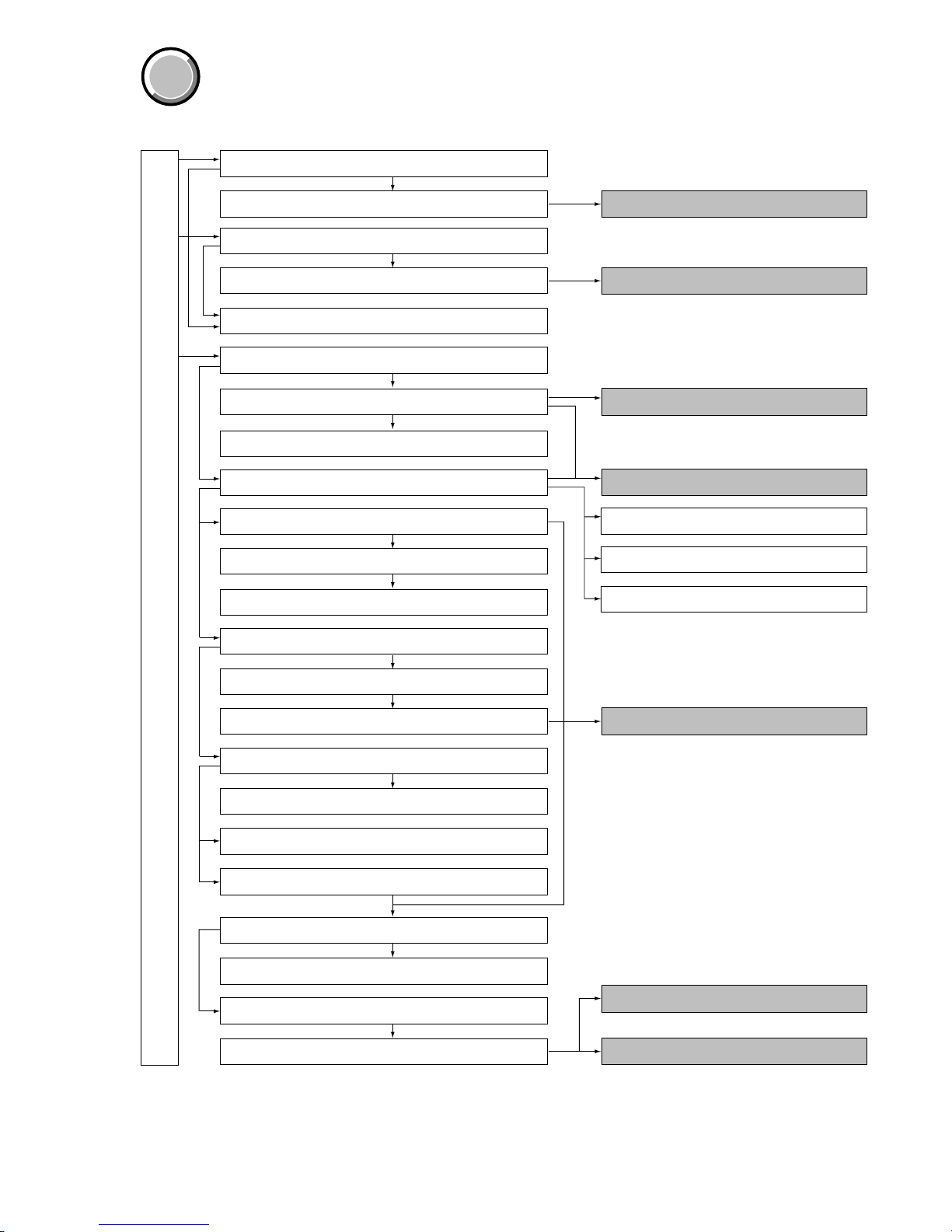
The following flow chart shows the disassembly procedure.
DCR-TRV738E/TRV740/TRV740E/TRV840
2-3. 3.5 inch LCD unit, PD-156/160 board -1
2-1. 2.5 inch LCD unit, PD-156/160 board -1
2-2. 2.5 inch LCD unit, PD-156/160 board -2 PD-156/160 board service position
2-4. 3.5 inch LCD unit, PD-156/160 board -2
2-5. Back light
PD-156/160 board service position
2-6. Front panel section
2-7. SI-032 board
2-8. Microphone
SI-032 board service position
LB-076 boards service position
CD-358 boards service position
2-9. Cabinet (R) section
2-10. Lens section
2-11. CD-358 board
2-12. Iris flexible assembly
2-26. Hinge section
2-24. Control switch block (CF-2500)
2-25. Control switch block (FK-2500)
2-15. LB-076 board -2
2-17. Battery terminal board
2-14. LB-076 board -1
2-13. EVF section
2-16. Battery panel section
2-18. Memory Stick 10P Connector
2-19. Control switch block (SS-1380)
2-20. Cabinet (L) section
2-21. CS frame assembly (25)
2-22. VC-278 board
2-23. Mechanism deck
Service position to check the VTR section
Service position to check the camera section
2.5 inch LCD model : TRV738E/TRV740/TRV740E
3.5 inch LCD model : TRV840
2-2
DCR-TRV738E/TRV740/TRV740E/TRV840
NOTE: Follo w the disassembly procedure in the numerical order given.
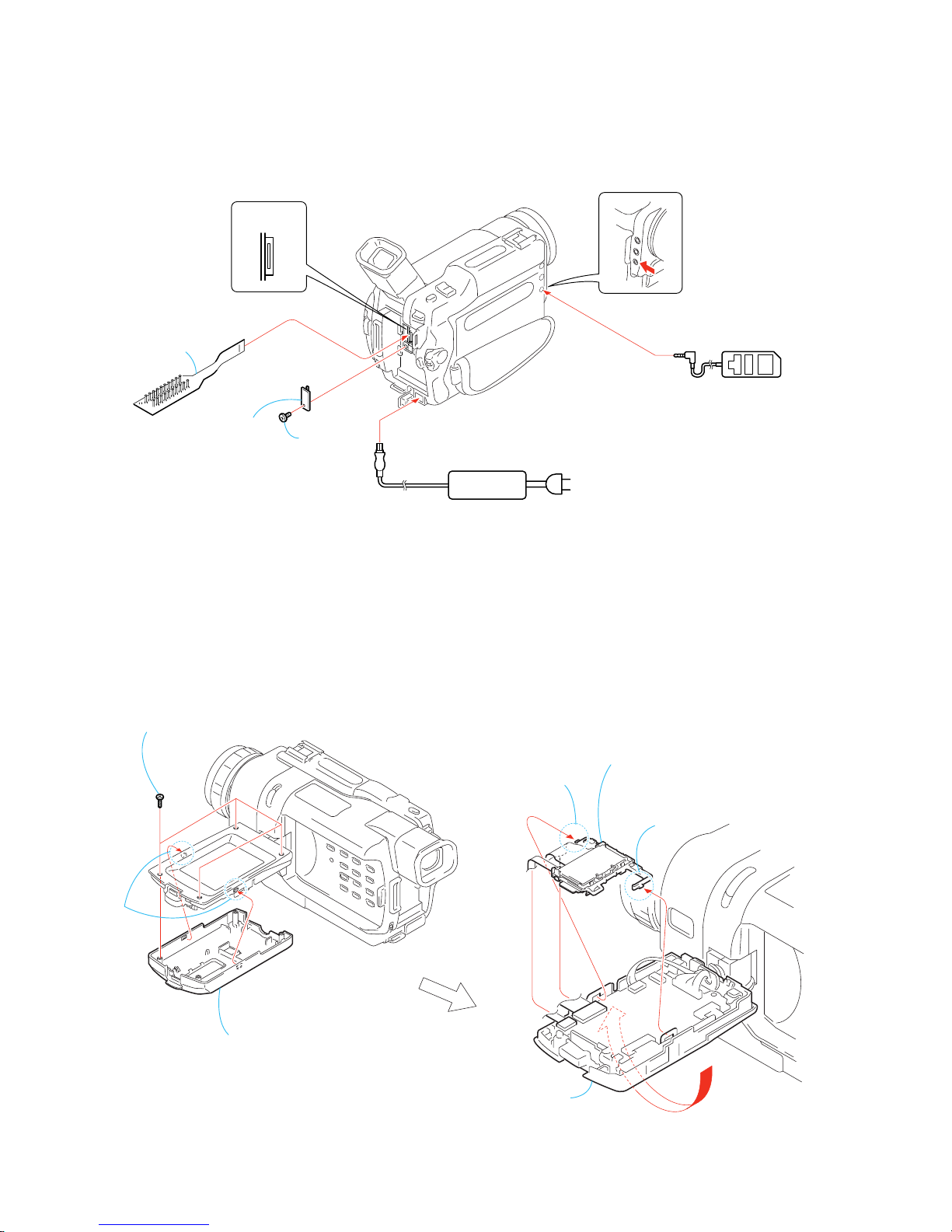
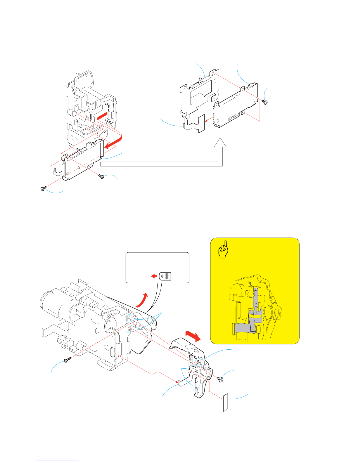
2-1. 2.5 INCH LCD UNIT, PD-156/160 BOARD -1
[CONNECTION OF EQUIPMENTS]
AC IN
AC power
adaptor
MI screw
(M2
×
4) (H)
CPC lid (BT)
CN1108
20
1
Adjustment remote
commander (RM-95)
CPC-13 jig
(J-6082-443-A)
6
Claw
5
Claw
2
Two
claws
1
Four tapping screws (M1.7 × 5)
3
P cabinet (C (2))
7
Indication LCD block assembly,
LCD holder, Back light
4
Reversed the LCD unit
in the direction of the arrow
A
.
A
NOTE: PD-156 board : TRV738E/TRV740E (AEP,EE,NE,RU)
PD-160 board : TRV740/TRV740E (E,HK,AUS,CH,JE)
Refer to page 5-32 for 1-5-1. “LCD Type Check” of this manual for the detail.
HK : Hong Kong model
AUS : Australian model
CH : Chinese model
JE : T ourist model
EE : East European model
NE : North European model
RU : Russian model
2-3
DCR-TRV738E/TRV740/TRV740E/TRV840
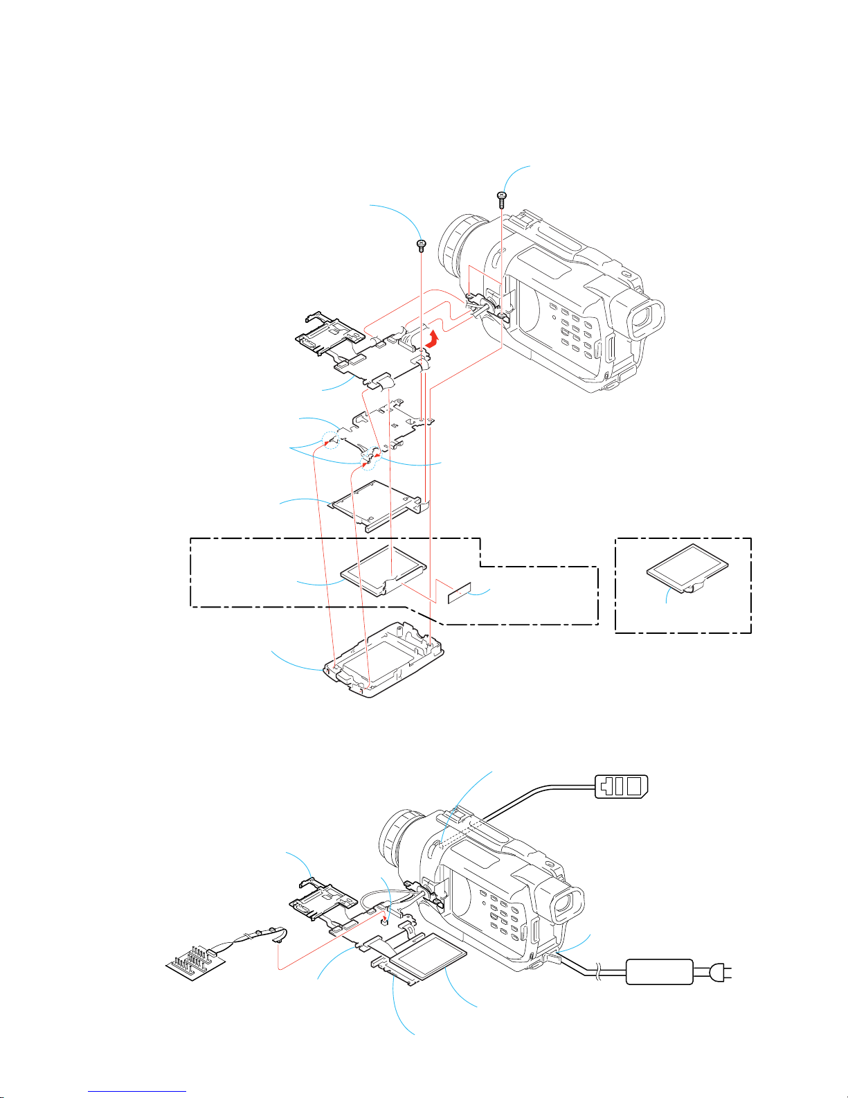
2-2. 2.5 INCH LCD UNIT, PD-156/160 BOARD -2
PD-156/160
Board
P
D
-15
6/1
60
B
oa
rd
[PD-156/160 BOARD SERVICE POSITION]
Back light (Cold cathode fluorescent tube)
Adjustment remote
commander (RM-95)
PD-156/160
board
Multi CPC jig
(J-6082-311-A)
Liquid crystal indicator module
Indication LCD block assembly
LANC jack
CN5502
DC IN
AC POWER
ADAPTOR
AC IN
7
Claw
A
9
P frame (2)
6
Back light
(Cold cathode
fluorescent tube)
1
Two tapping screws
(B1.7
×
6)
7
P screw (M1.7 × 2.5)
4
P cabinet (M) (2) assembly
8
Remove the PD-156/160 board
in the direction of the arrow
A
.
4
Liquid crystal
indicator module
3
T wo claws
(TRV740/
TRV740E : E,HK,AUS,CH,JE)
(TRV738E/
TRV740E : AEP,EE,NE,RU)
2
LCD insulating
sheet (SH)
5
Liquid crystal
indicator module
HK : Hong Kong model
AUS : Australian model
CH : Chinese model
JE : T ourist model
EE : East European model
NE : North European model
RU : Russian model
NOTE: PD-156 board : TRV738E/TRV740E (AEP,EE,NE,RU)
PD-160 board : TRV740/TRV740E (E,HK,AUS,CH,JE)
Refer to page 5-32 for 1-5-1. “LCD Type Check” of this manual for the detail.
2-4
DCR-TRV738E/TRV740/TRV740E/TRV840
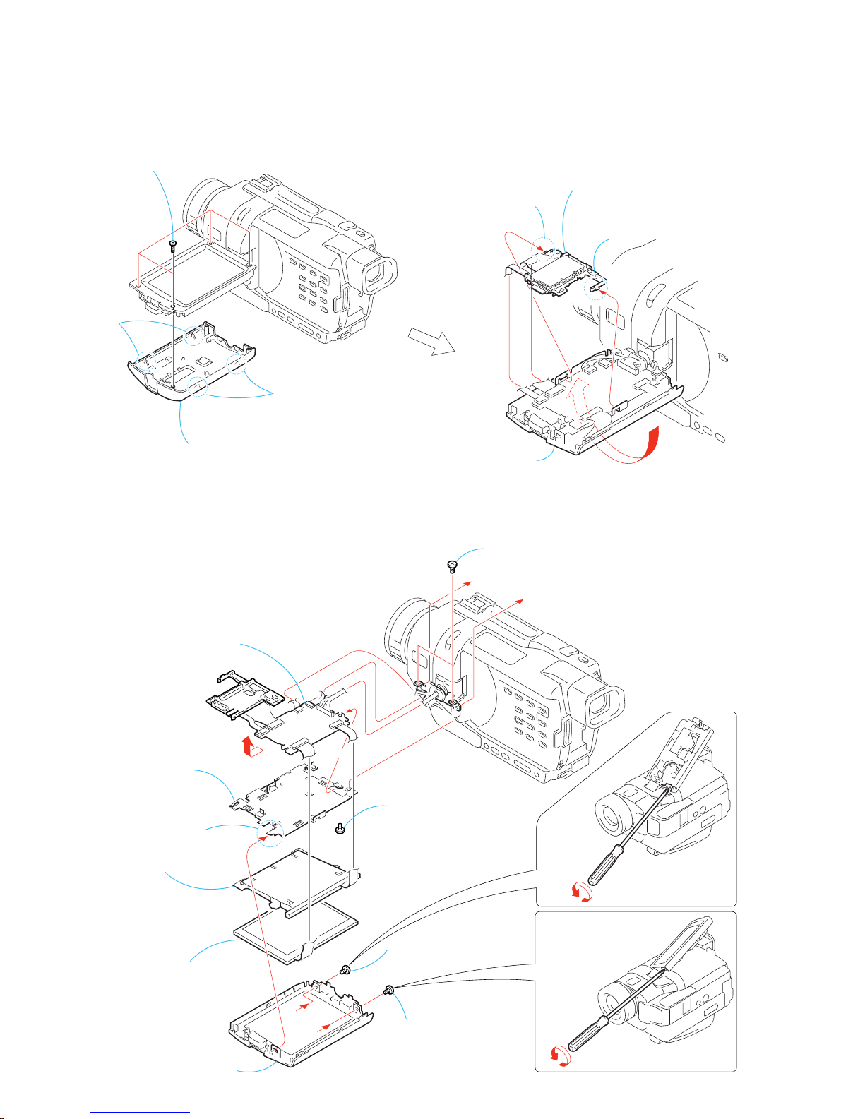
2-3. 3.5 INCH LCD UNIT, PD-156/160 BOARD -1
1
Four tapping screws (M1.7 × 5)
2
Two
claws
2
Two
claws
6
Claw
7
LCD block assembly,
LCD holder, Back light
5
Claw
4
Reversed the LCD unit
in the direction of the arrow
A
.
A
3
P cabinet (C) (3) assembly
2-4. 3.5 INCH LCD UNIT, PD-156/160 BOARD -2
PD-156/160
Board
4
Claw
C
B
A
5
P cabinet (M) (2) assembly
8
Screw (M1.7 × 2.5), p
1
Screw (M1.7 × 2.5), p
2
Screw
(M1.7
×
2.5), p
3
Two screws (M1.7 × 2.5), p
B
A
q;
P frame (2)
7
Back light
(Cold cathode fluorescent tube)
9
Remove the PD-156/160 board
in the direction of the arrow
C
.
6
Liquid crystal
indicator module
NOTE: 3.5 inch LCD model is TRV840 only.
Refer to page 5-32 for 1-5-1. “LCD Type Check” of this manual for the detail.
NOTE: 3.5 inch LCD model is TRV840 only.
Refer to page 5-32 for 1-5-1. “LCD Type Check” of this manual for the detail.
2-5
DCR-TRV738E/TRV740/TRV740E/TRV840
2-5. BACK LIGHT
PD-156/160
Board
[PD-156/160 BOARD SERVICE POSITION]
Back light (Cold cathode fluorescent tube)
Adjustment remote
commander (RM-95)
PD-156/160
board
Multi CPC jig
(J-6082-311-A)
Liquid crystal indicator module
Indication LCD block assembly
LANC jack
CN5502
DC IN
AC POWER
ADAPTOR
AC I
N
2
FP-414 flexible
board (4P)
1
Indication LCD
block assembly (20P)
6
Two claws
4
Four claws
Two claws
B
qa
Back light
C
D
9
Remove
the two
solderings.
8
LCD holder
5
Remove the indication LCD block assembly
in the direction of the arrow
B
.
7
Remove the back light, flexible flat cable (FP-414
)
in the direction of the arrow C to D.
3
Push this point to
remove the two
claws.
q;
FP-414
flexible board
2-6
DCR-TRV738E/TRV740/TRV740E/TRV840
2-6. FRONT PANEL SECTION
1
When removing Front panel section, do not
press down the drum of mechanism deck.
The drum of
mechanism deck.
2
MI screw
(M2
×
4) (H)
3
MI screw
(M2
×
4) (H)
6
FP-406 flexible
board (30P)
4
Two MI screws
(M2
×
4) (H)
Push the eject knob in
the direction of the arrow
A
,
and open the cassette lid.
A
7
Front panel section
5
Claw
Remove it while taking
care as the FP-406 flexible
cable is connected.
Caution
2-7. SI-032 BOARD
B
7
SI-032 board
1
Cushion (1), F
3
Tapping screw
(M1.7
×
5)
2
Two tapping screws
(M1.7
×
5)
6
Tapping screw
(M1.7
×
5)
4
Remove the FP-411 flexible board
in the direction of the arrow
B
.
5
Microphone (4P)
2-7
DCR-TRV738E/TRV740/TRV740E/TRV840
2-8. MICROPHONE
FP-406 flexible
board (30P)
SI-032 board
[SI-032 BOARD SERVICE POSITION]
AC I
N
AC POWER
ADAPTOR
DC IN
FP-411 flexible
board
8
Front panel
assembly (24)
2
Sheet microphone
Microphone
When removing it, be careful not
to damage the harnesses, etc.
Microphone retainer (rear view)
Microphone
holder
4
Microphone retainer
6
Microphone
holder
1
Tapping screw
(M1.7 × 5)
5
Microphone
7
Microphone
Cushion (F)
3
Two claws
Caution
2-8
DCR-TRV738E/TRV740/TRV740E/TRV840
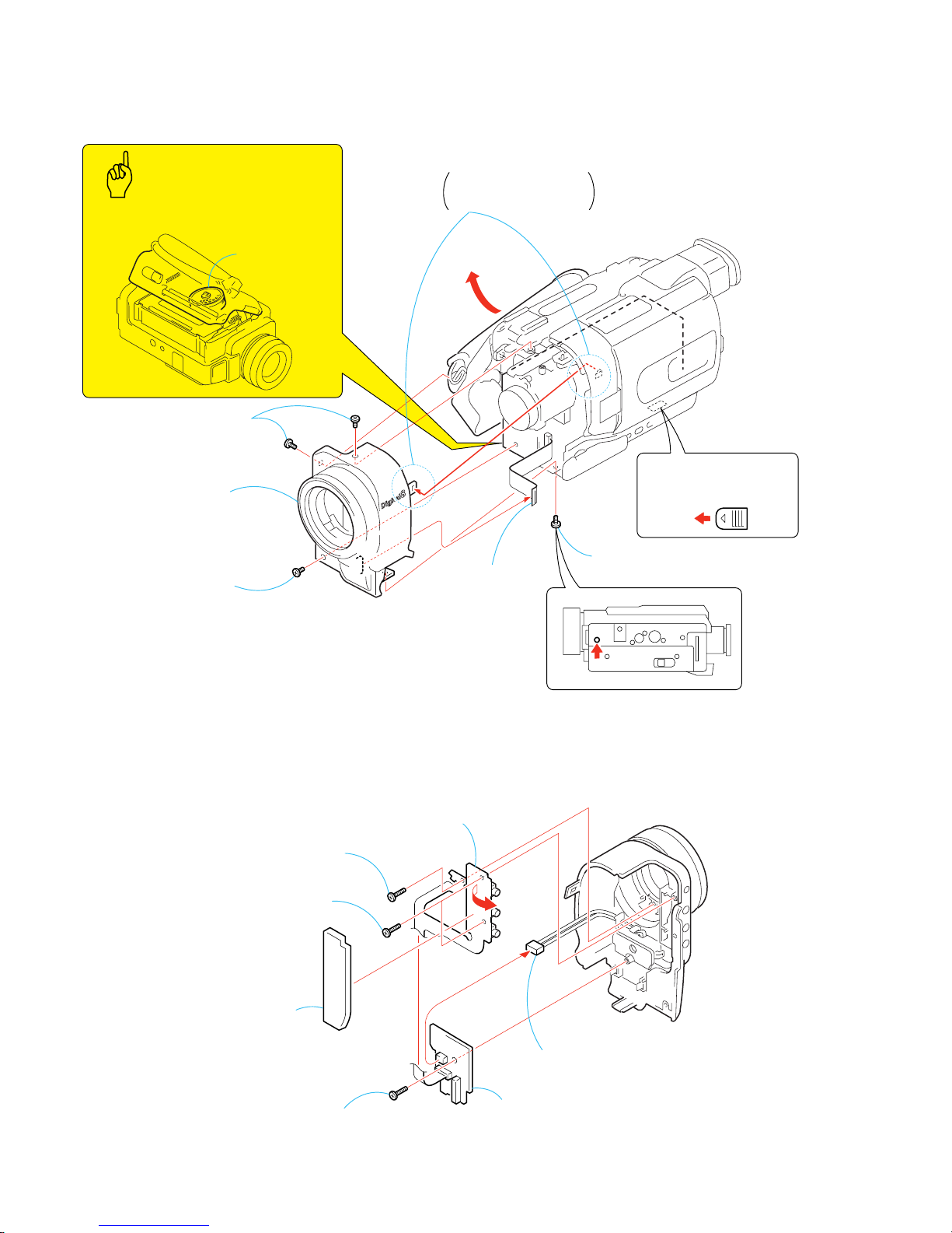
2-9. CABINET (R) SECTION
2
Three claws
5
Claw
7
Claw
qh
Cabinet (R) block
section
qg
Harness
(PD-117) (20P)
3
Cabinet
(upper)
qd
Night-Shot switch of
Lens device (LSV-740A)
1
MI screw
(M2
×
4) (H)
qf
Control switch block
(CF-2500) (22P)
q;
Three MI screws
(M2
×
4) (H)
qa
Three MI screws
(M2
×
4) (H)
4
MI screw
(M2
×
4) (H)
9
MI screw
(M2
×
4) (H)
6
Jack cover retainer
8
Jack cover
qs
Two MI screws
(M2
×
4) (H)

2-9
DCR-TRV738E/TRV740/TRV740E/TRV840
2-10.LENS SECTION
2-11.CD-358 BOARD
1
Two screws
(M1.7
×
2.5), p
2
FP-317 flexible
board (24P)
3
Iris (IR740) (24P)
4
Lens section
2
Two tapping
screws (B1.7 × 6)
1
FP-317 flexible
board (24P)
4
Seal rubber (W)
7
CD-358 board
3
Optical filter block
6
CCD block assembly
5
Remove the soldering
s
8
Lens device (LSV-740A)
2-10
DCR-TRV738E/TRV740/TRV740E/TRV840
2-12.IRIS FLEXIBLE ASSEMBLY
LANC jack
CD-358 board
[CD-358 BOARD SERVICE POSITION]
AC I
N
AC POWER
ADAPTOR
DC IN
Adjustment remote
commander (RM-95)
SI-032 board
Cabinet (R) block section
Control switch block
(CF-2500) (22P)
Harness
(PD-117) (20P)
FP-406 flexible
board (30P)
FP-411 flexible
board
6
Tapping screw (M1.7 × 5)
q;
3
Remove the eight
solderings
7
Tapping screw
(M1.7
×
5)
1
Two tapping
screws (M1.7
×
5)
8
Two tapping screws
(B1.7
×
3.5), head
9
Iris (IR740)
2
Two tapping
screws (M1.7
×
5)
4
Stepping
motor Z740A
(Zoom)
5
Stepping
motor F740
A
(Focus)
A
A
B
B
2-11
DCR-TRV738E/TRV740/TRV740E/TRV840
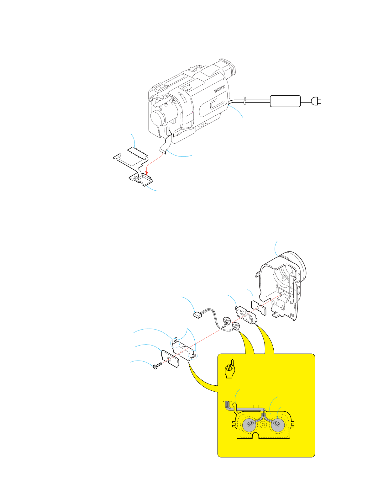
2-13.EVF SECTION
2-14.LB-076 BOARD -1
5
EVF section
1
FP-407 flexible
board (20P)
A
A
4
Routing of the flexible board of
the Operation FP-407 flexible board
when attaching the EVF section.
2
MI screw
(M2 × 4) (H)
3
Three screws
(M1.7 × 2.5), p
Caution
VF hinge assembly
PRECAUTION WHEN ATTACHING
FP-407 FLEXIBLE BOARD
FP-407
flexible board
6
EVF cabinet
(upper) assembly
8
EVF cabinet
(lower) assembly
9
FP-407 flexible
board (20P)
5
Claw
2
Slide the lower plate of
VF hinge assembly in
the arrow A strongly.
1
Pull of the
adhesive side.
A
7
Fix the FP-407 flexible board to VF hinge assembly
with the both-sided adhesive tape.
3
Two tapping
screws (M1.7 × 5)
4
Four tapping
screws
(M1.7 × 5)
q;
LB-076 board,
VF lens (B) assembly,
etc.
Routing of the flexible board of the
Operation FP-407 flexible board when
attaching t h e EVF cabinet (lower)
assembly.
Caution
2-12
DCR-TRV738E/TRV740/TRV740E/TRV840
2-15.LB-076 BOARD -2
1
T wo claws
2
T wo claws
9
VF lens (B) assembly
6
Illuminator
4
LCD (LCX032AP-5)
(16P)
8
LCD
(LCX032AP-5)
7
Prism sheet
3
Lamp guide
5
LB-076 board
[LB-076 BOARD SERVICE POSITION]
FP-407 flexible
board (20P)
LB-076 board
AC IN
AC POWER
ADAPTOR
DC IN
CPC-13 jig
(J-6082-443-A)
Adjustment remote
commander (RM-95)
SI-032 board
Cabinet (R) block section
Control switch block
(CF-2500) (22P)
Harness
(PD-117) (20P)
FP-406 flexible
board (30P)
LANC jack
FP-411 flexible
board
2-13
DCR-TRV738E/TRV740/TRV740E/TRV840
2-16.BATTERY PANEL SECTION
2-17.BATTERY TERMINAL BOARD
6
Two MI screws
(M2
×
4) (H)
5
MI screw
(M2
×
4) (H)
9
Battery panel
section
2
Ferrite bead
1
Tape (A)
8
A
7
Tapping screw
(M1.7
×
5)
3
FP-409 flexible
board (10P)
4
Battery terminal
board (6P)
A
2
MI screw
(M2 × 4) (H
)
3
4
5
Strap sheet
metal (lower)
6
Battery terminal board
1
Jack lid
(2500)
2-14
DCR-TRV738E/TRV740/TRV740E/TRV840
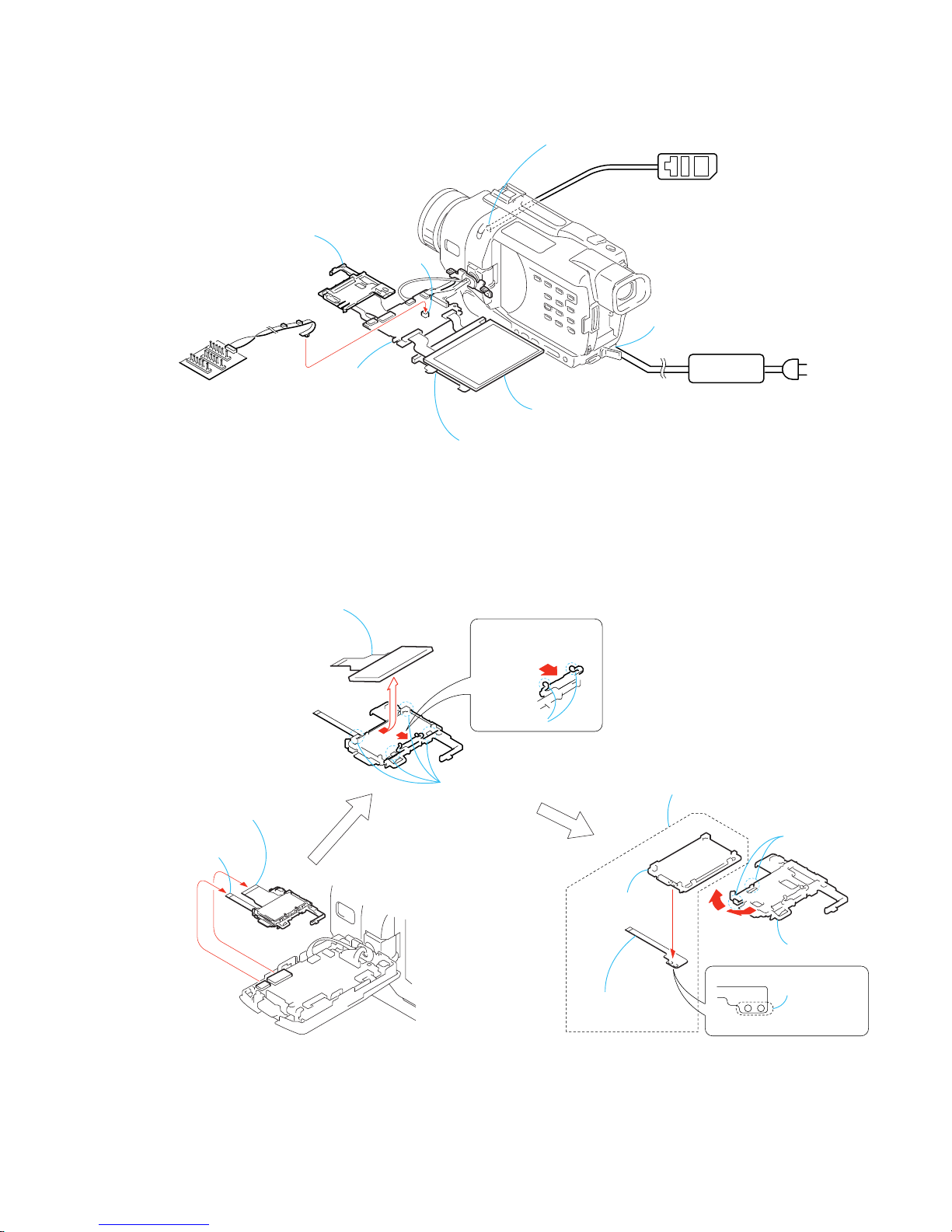
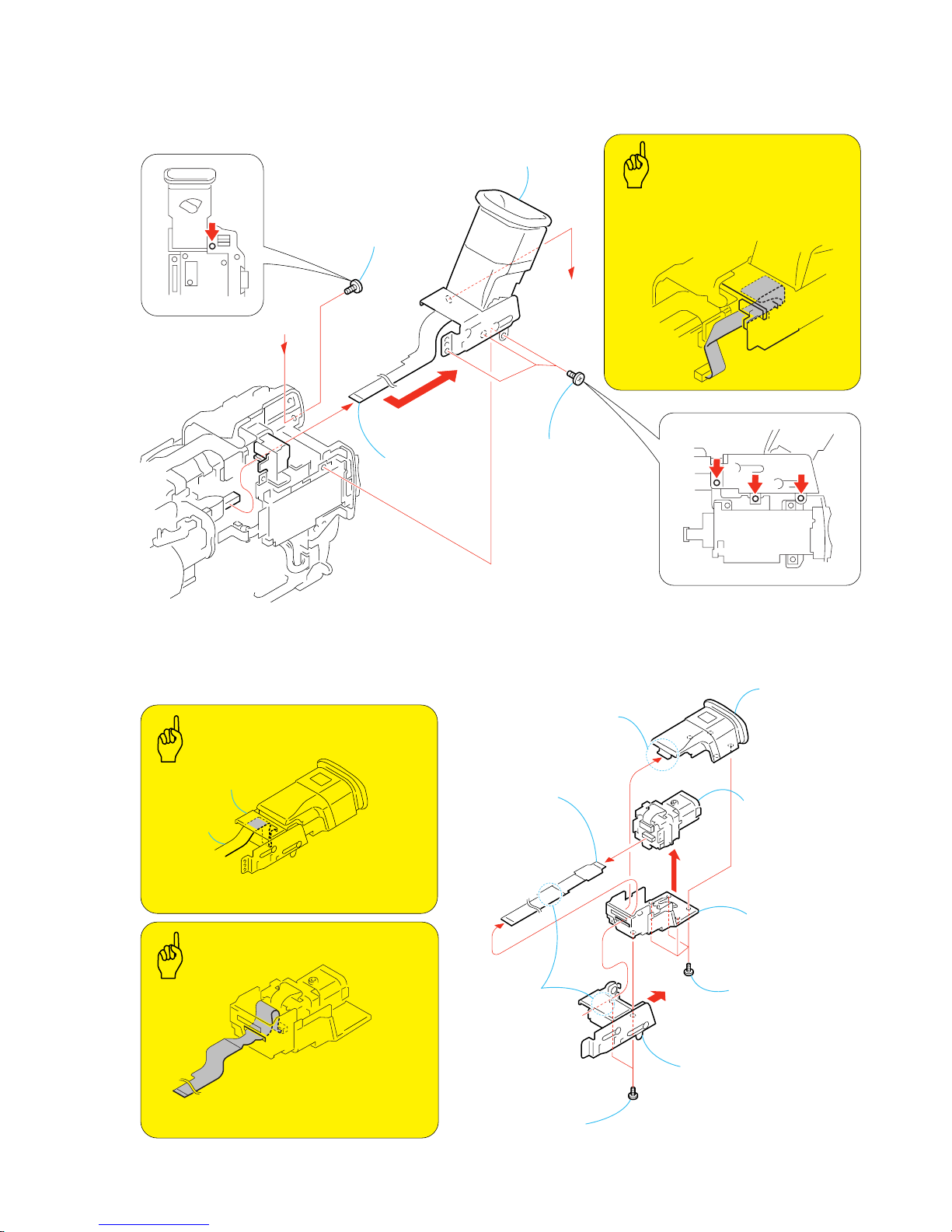
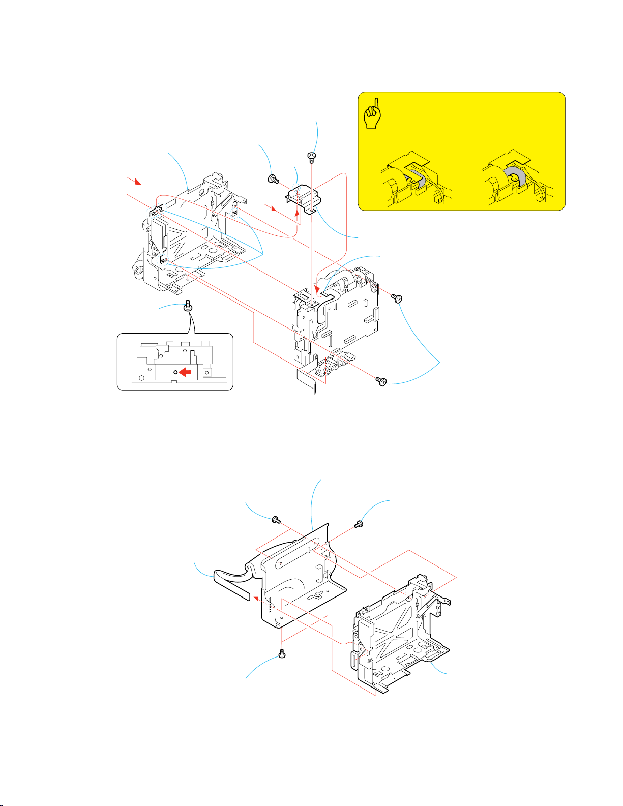
2-18.MEMORY STICK 10P CONNECTOR
2-19.CONTROL SWITCH BLOCK (SS-1380)
8
Memory stick 10p connector
7
MS holder
4
MS section
2
Two screws
(M1.7
×
2.5), p
1
Screw
(M1.7
×
2.5), p
3
6
Two screws
(M1.7
×
2.5), p
5
FP-409 flexible board
(10P)
B
6
8
Remove the control switch block
(SS-1380) in the direction
of the arrow B.
3
Screw (M1.7 × 2.5), p
4
Two dowels
7
Two dowels
1
T ape (A)
5
T apping screw
(M1.7 × 5)
VC-278
Board
2
Control switch block
(SS-1380) (12P)
Push the eject knob in
the direction of the arrow
A
,
and open the cassette lid.
A
Routing of the flexible board of the
Operation Control switch block (SS-1380).
Caution
2-15
DCR-TRV738E/TRV740/TRV740E/TRV840
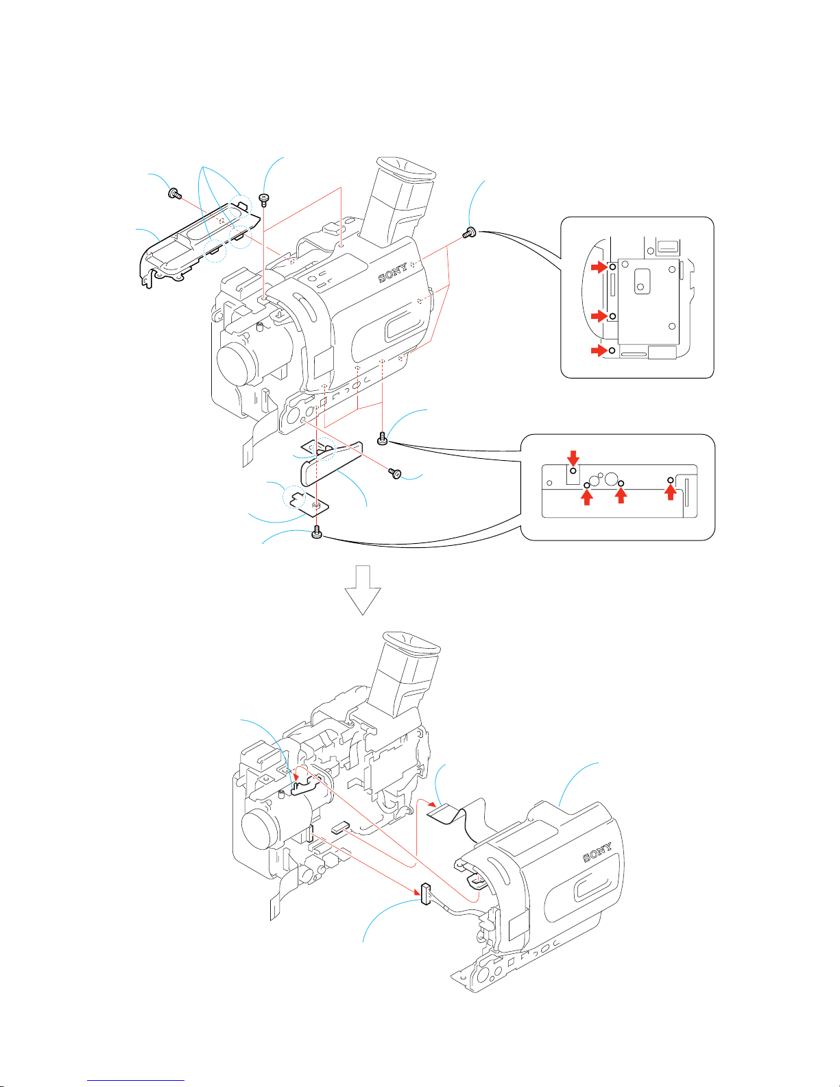
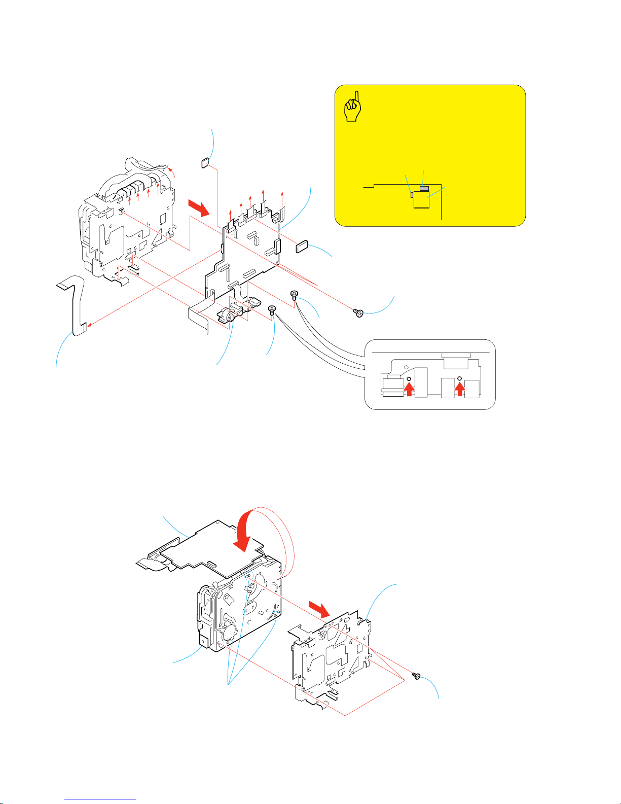
2-20.CABINET (L) SECTION
2-21.CS FRAME ASSEMBLY (25)
VC-278
Board
8
Four
dowels
3
Claw
9
Cabinet (L)
section
5
External (hot shoe) connector,
Shoe frame
6
Two screws
(M1.7 × 2.5), p
2
Screw
(M1.7 × 2.5), p
7
Screw
(M1.7 × 2.5), p
1
Screw
(M1.7 × 2.5), p
A
A
4
FP-264 flexible
board (15P)
PRECAUTION DURING
CABINET (L) SECTION INSTALLATION
OK NG
5
Cabinet (L) assembly
1
MI screw
(M2
×
4) (H)
3
T wo MI screws (M2 × 4) (H)
2
T wo MI screws (M2 × 4) (H)
4
Grip belt (ES)
6
CS frame assembly (25)
2-16
DCR-TRV738E/TRV740/TRV740E/TRV840
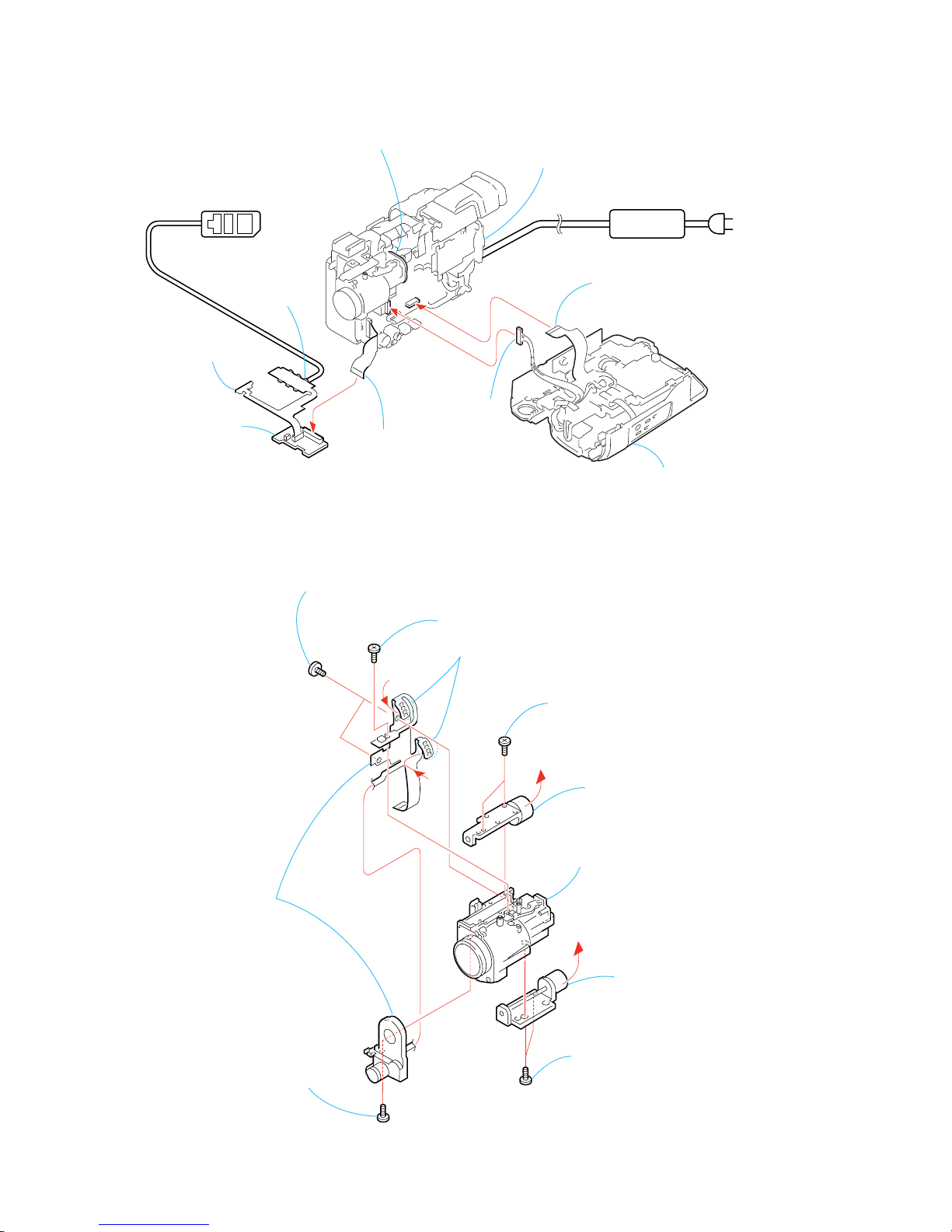
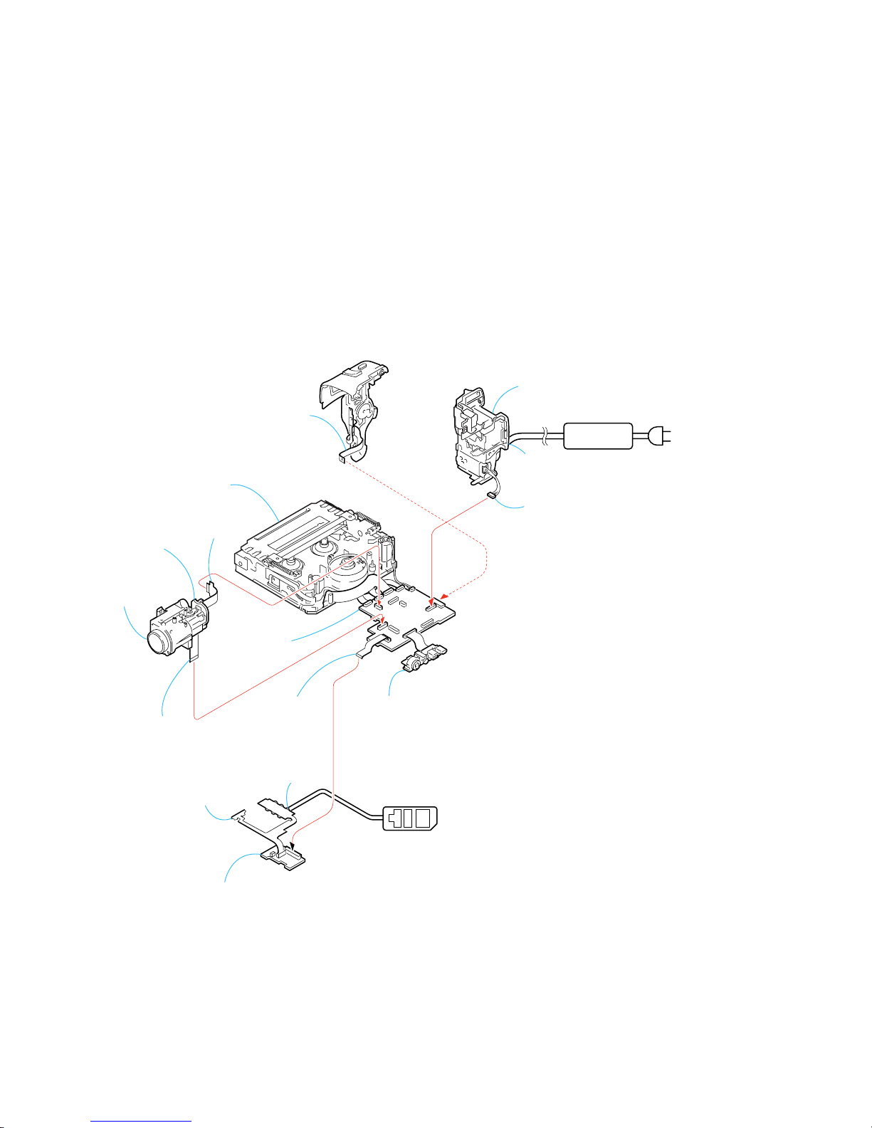
2-22.VC-278 BOARD
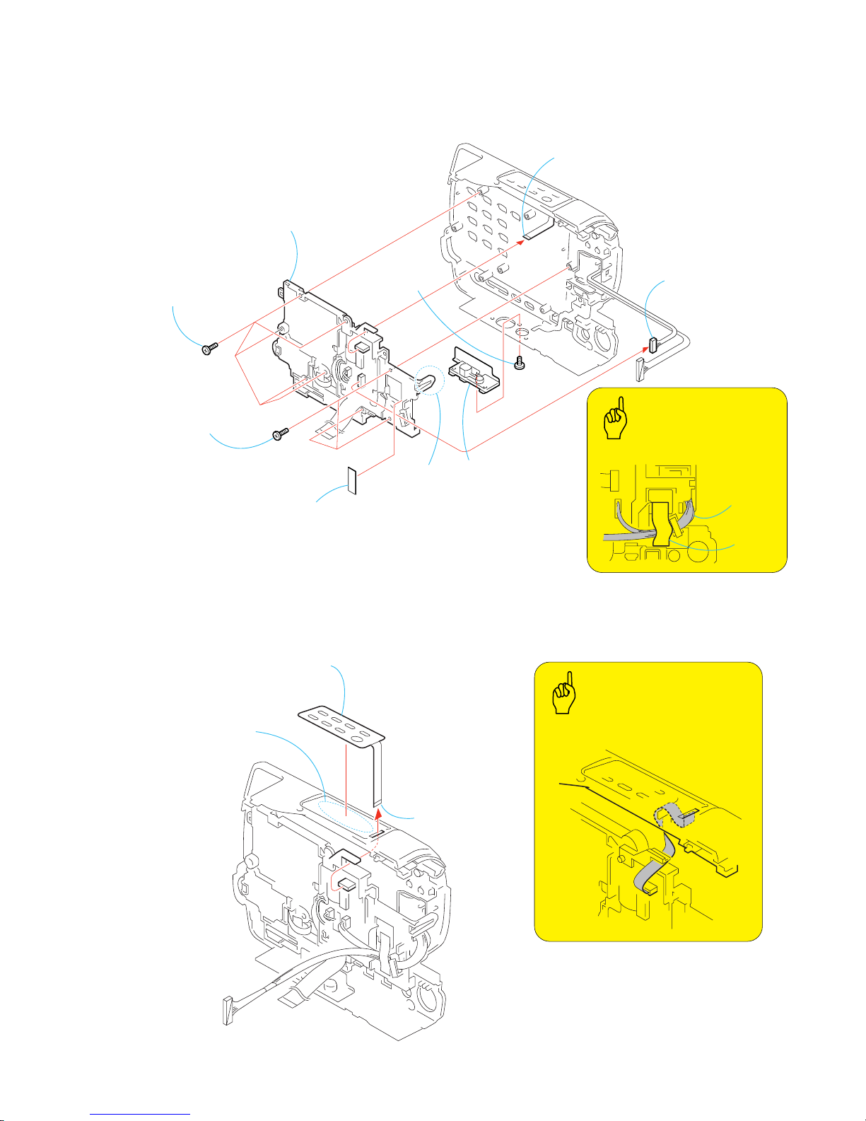
2-23.MECHANISM DECK
VC-278
Board
D
B
A
C
E
D
E
C
B
A
7
VC sheet
9
VC-278
board
2
Screw
(M1.7
×
2.5), p
4
Two screws
(M1.7
×
2.5), p
5
3
FP-410
flexible board
6
FP-264 flexible
board (20P)
8
SHEET (25) 2, M
SHEET (25), M
VIBRATOR
CAPACITOR
VC-278 board
Side B
1
MI screw
(M2 × 4) (H)
Attach the Sheet (25) 2, M so that Sheet (25) 2, M
does not overlap with Capacitor and Vibrator,
when attach the Sheet (25) 2, M to the VC-278 board.
Caution
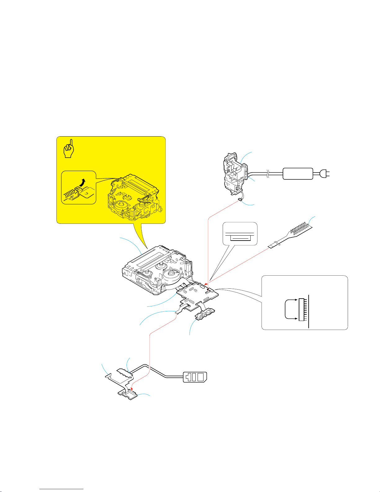
5
MD frame
4
1
T urn over VC-278 board
in the direction of the arrow.
6
Mechanism
deck
VC-278
Board
2
Three screws
(M1.7
×
2.5), p
3
Three dowels
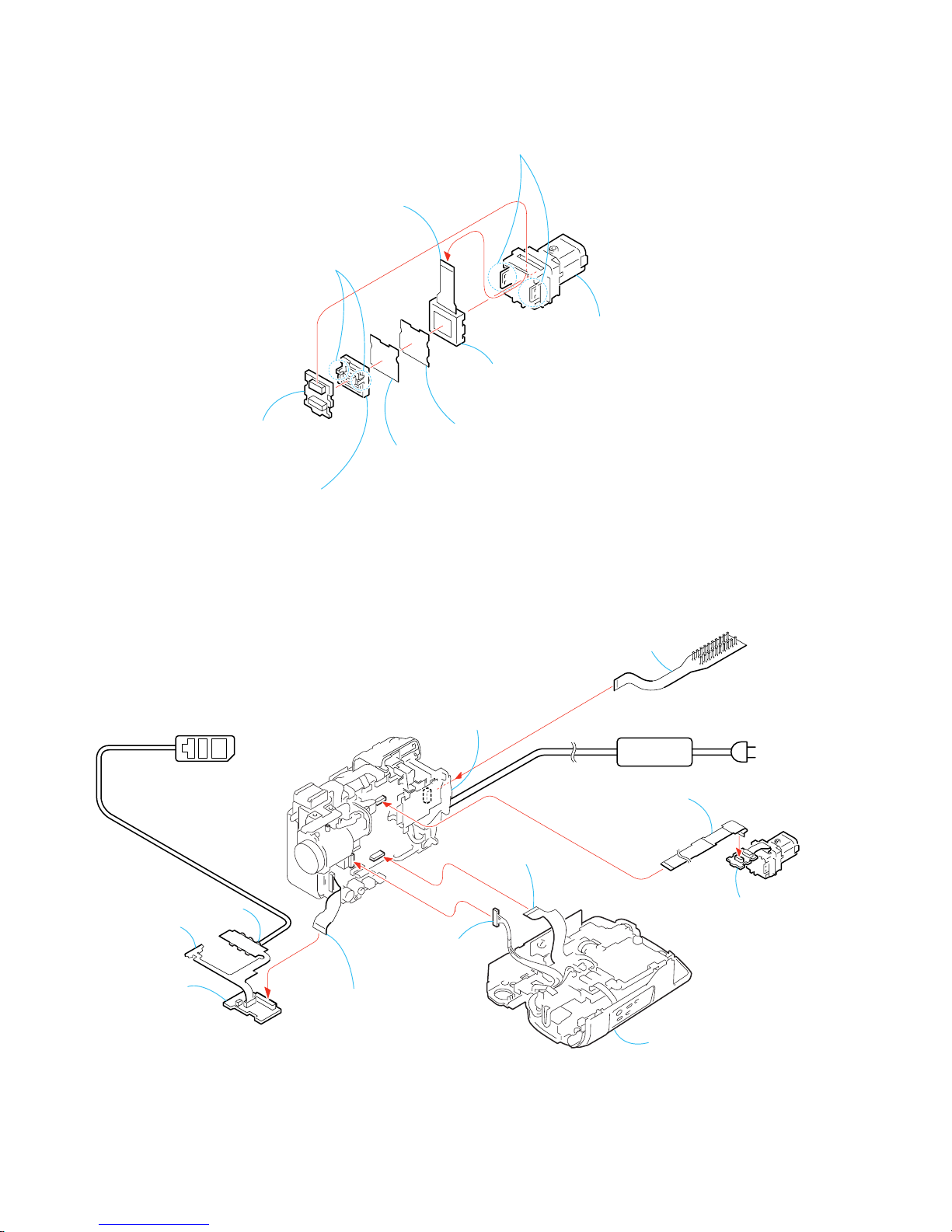
2-17
DCR-TRV738E/TRV740/TRV740E/TRV840
Adjustment remote
commander (RM-95)
AC IN
DC IN
AC POWER
ADAPTOR
FP-406 flexible
board (30P)
Mechanism deck
CPC-13 jig
(J-6082-443-A)
FP-410
flexible board
FP-411
flexible board
SI-032 board
Battery panel
section
Battery terminal
board (6P)
VC-278
board
LANC
jack
VC-278
Board
(Raise the hook in the direction of the arrow A.)
How to raise the cassette
compartment manually
CN1109
CN1108
12
2
To eject the cassette, short the circuit
between pin
qs
and pin 2 (GND) of
CN1109 on VC-276 board for 1 second.
To check the VTR section, set the VTR to the “Forced VTR power ON” mode.
Operate the VTR functions using the adjustment remote commander (with the HOLD switch set in the OFF position).
[SERVICE POSITION TO CHECK THE VTR SECTION]
Setting the “Forced VTR Power ON” mode
Cnnection to Check the VTR Section
1) Select page: 0, address: 01, and set data: 01.
2) Select page: 0, address: 10, and set data: 00.
3) Select page: D, address: 10, set data: 02 and
press the PAUSE button of the adjustment remote
commander.
Exiting the “Forced VTR Power ON” mode
1) Select page: 0, address: 01, and set data: 01.
2) Select page: 0, address: 10, and set data: 00.
3) Select page: D, address: 10, set data: 00, and press
the PAUSE button of the adjustment remote commander.
4) Select page: 0, address: 01, and set data: 00.
Note : If the machine malfunctions (the operating mode changes by itself), connect the Cabinet (R) section.
A
2-18
DCR-TRV738E/TRV740/TRV740E/TRV840
Adjustment remote
commander (RM-95)
AC IN
DC IN
AC POWER
ADAPTOR
FP-406 flexible
board (30P)
Control switch block
(SS-1380) (12P)
Mechanism deck
FP-410
flexible board
FP-317 flexible
board (16P)
Iris flexible
assembly (24P)
Battery panel
section
Battery terminal
board (6P)
VC-278
board
Lens section
LANC
jack
SI-032 board
V
C
-2
78
B
oa
rd
CD-358 board
FP-411
flexible board
[SERVICE POSITION TO CHECK THE CAMERA SECTION]
Connection to Check the Camera Section
To check the camera section, set the camera to the “Forced camera power ON” mode.
When you want to operate to focus, use the controls on the remote commander (with the HOLD switch off).
Setting the “Forced Camera Power ON” mode
1) Select page: 0, address: 01, and set data: 01.
2) Select page: 0, address: 10, and set data: 00.
3) Select page: D, address: 10, set data: 01 and
press the PAUSE button of the adjustment remote
commander.
Exiting the “Forced Camera Power ON” mode
1) Select page: 0, address: 01, and set data: 01.
2) Select page: 0, address: 10, and set data: 00.
3) Select page: D, address: 10, set data: 00, and press
the PAUSE button of the adjustment remote
commander.
4) Select page : 0, address: 01, and set data: 00.
When you want to operate to zoom, connect the controls switch block (SS-1380).
2-19
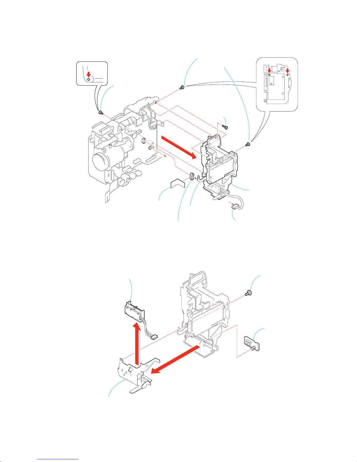
DCR-TRV738E/TRV740/TRV740E/TRV840
2-24.CONTROL SWITCH BLOCK (CF-2500)
2-25.CONTROL SWITCH BLOCK (FK-2500)
6
Five tapping screws
(B2
×
5)
6
Three tapping screws
(B2
×
5)
4
T ape (A)
Tape (A)
8
Control switch block
(CF-2500)
3
Control switch block
(FK-2500) (5P)
5
Harness (PD-117)
(6P)
Harness
(PD-117)
1
MI screw
(M2
×
4) (H)
2
T ripod retainer,
Tripod screw (Y)
7
Claw
Routing of the harness (PD-117) .
Caution
3
Control switch block
(FK-2500)
1
Control switch block
(FK-2500) (5P)
2
Peel off the
adhesive side.
Routing of the flexible board of the
Operation Control switch block (FK-2500).
Caution
 Loading...