

Sony TRV140E, TRV140M Service Manual
SERVICE MANUAL
Viewfinder
Electric Viewfinder (monochrome)
Image device
4.5 mm (1/4 type) CCD
(Charge Coupled Device)
DCR-TRV140/TRV140M:
Approx. 460 000 pixels
(Effective: Approx. 290 000 pixels)
DCR-TRV140E:
Approx. 540 000 pixels
(Effective: Approx. 350 000 pixels)
Lens
Combined power zoom lens
Filter diameter 37 mm (1 7/16 in.)
20× (Optical), 560×
(Digital)
Focal length
3.6 - 72 mm (5/32 - 2 7/8 in.)
When converted to a 35 mm
still camera
41 - 820 mm (1 5/8 - 32 3/8 in.)
Colour temperature
Auto
Minimum illumination
1 lx (lux) (F 1.4)
0 lx (lux) (in the NightShot mode)*
* Objects unable to be seen due to
the dark can be shot with infrared
lighting.
Video camera
recorder
System
Video recording system
2 rotary heads
Helical scanning system
Audio recording system
Rotary heads, PCM system
Quantization: 12 bits (Fs 32 kHz,
stereo 1, stereo 2), 16 bits
(Fs 48 kHz, stereo)
Video signal
DCR-TRV140/TRV140M:
NTSC color, EIA standards
DCR-TRV140E:
PAL colour, CCIR standards
Recommended cassette
Hi8/Digital8 video cassette
Recording/playback time (using
90 min. Hi8/Digital 8 video
cassette)
SP mode: 1 hour
LP mode: 1 hour and 30 minutes
Fastforward/rewind time (using
90 min. Hi8/Digital 8 video
cassette)
Approx. 5 min.
Input/output
connectors
S video output
DCR-TRV140/TRV140M:
4-pin mini DIN
Luminance signal: 1 Vp-p,
75 Ω (ohms), unbalanced
Chrominance signal: 0.286 Vp-p,
75 Ω (ohms), unbalanced
DCR-TRV140E:
4-pin mini DIN
Luminance signal: 1 Vp-p,
75 Ω (ohms), unbalanced
Chrominance signal: 0.3 Vp-p,
75 Ω (ohms), unbalanced
Audio/Video output
AV MINIJACK, 1 Vp-p, 75 Ω
(ohms), unbalanced, sync negative
327 mV, (at output impedance more
than 47 kΩ (kilohms))
Output impedance with less than
2.2 kΩ (kilohms)/Stereo minijack
(ø 3.5 mm)
DCR-TRV140/TRV140E:
E, HK, AUS, CH, JE/TRV140M
DV input/output
4-pin connector
DCR-TRV140E:
AEP, UK, EE, NE, RU
DV output
4-pin connector
USB jack
Mini-B
LCD screen
Picture
6.2 cm (2.5 type)
50.3 × 37.4 mm
(2 × 1 1/2 in.)
Total dot number
61 600 (280 × 220)
General
Power requirements
7.2 V (battery pack)
8.4 V (AC power adaptor)
Average power consumption
(when using the battery pack)
During camera recording using
LCD
3.5 W
Viewfinder
2.8 W
DIGITAL VIDEO CAMERA RECORDER
SPECIFICATIONS
RMT-814
DCR-TRV140/TRV140E/TRV140M
US Model
DCR-TRV140/TRV140M
Canadian Model
DCR-TRV140
AEP Model
UK Model
East European Model
North European Model
Russian Model
DCR-TRV140E
E Model
Hong Kong Model
DCR-TRV140/TRV140E
Brazilian Model
DCR-TRV140
Australian Model
Chinese Model
DCR-TRV140E
Tourist Model
DCR-TRV140/TRV140E
M2000 MECHANISM
– Continued on next page –
NTSC MODEL : DCR-TRV140/TRV140M
PAL MODEL : DCR-TRV140E
Photo: DCR-TRV140E
Ver 1.1 2003. 06
For MECHANISM ADJUSTMENT, refer to the “8mm
Video MECHANICAL ADJUSTMENT MANUAL IX
M2000 MECHANISM ” (9-929-861-11).
When the machine needs to be repaired,
please refer to page 7 to discriminate the
type of LCD.

– 2 –
DCR-TRV140/TRV140E/TRV140M
1. Check the area of your repair for unsoldered or poorly-soldered connections. Check the entire board surface for solder
splashes and bridges.
2. Check the interboard wiring to ensure that no wires are
“pinched” or contact high-wattage resistors.
3. Look for unauthorized replacement parts, particularly transistors, that were installed during a previous repair. Point them
out to the customer and recommend their replacement.
4. Look for parts which, though functioning, show obvious signs
of deterioration. Point them out to the customer and recommend their replacement.
5. Check the B+ voltage to see it is at the values specified.
6. Flexible Circuit Board Repairing
• Keep the temperature of the soldering iron around 270 ˚C
during repairing.
• Do not touch the soldering iron on the same conductor of
the circuit board (within 3 times).
• Be careful not to apply force on the conductor when sol-
dering or unsoldering.
SAFETY CHECK-OUT
After correcting the original service problem, perform the following
safety checks before releasing the set to the customer.
ATTENTION AU COMPOSANT AYANT RAPPORT
À LA SÉCURITÉ!
LES COMPOSANTS IDENTIFIÉS P AR UNE MARQUE 0
SUR LES DIAGRAMMES SCHÉMA TIQUES ET LA LISTE
DES PIÈCES SONT CRITIQUES POUR LA SÉCURITÉ
DE FONCTIONNEMENT. NE REMPLACER CES COMPOSANTS QUE PAR DES PIÈCES SONY DONT LES
NUMÉROS SONT DONNÉS DANS CE MANUEL OU
DANS LES SUPPLÉMENTS PUBLIÉS PAR SONY.
SAFETY-RELATED COMPONENT WARNING!!
COMPONENTS IDENTIFIED BY MARK 0 OR DOTTED
LINE WITH MARK 0 ON THE SCHEMA TIC DIAGRAMS
AND IN THE PARTS LIST ARE CRITICAL TO SAFE
OPERATION. REPLACE THESE COMPONENTS WITH
SONY PARTS WHOSE PART NUMBERS APPEAR AS
SHOWN IN THIS MANUAL OR IN SUPPLEMENTS PUBLISHED BY SONY.
UNLEADED SOLDER
Boards requiring use of unleaded solder are printed with the leadfree mark (LF) indicating the solder contains no lead.
(Caution: Some printed circuit boards may not come printed with
the lead free mark due to their particular size)
: LEAD FREE MARK
Unleaded solder has the following characteristics.
• Unleaded solder melts at a temperature about 40 ˚C higher than
ordinary solder.
Ordinary soldering irons can be used but the iron tip has to be
applied to the solder joint for a slightly longer time.
Soldering irons using a temperature regulator should be set to
about 350 ˚C .
Caution: The printed pattern (copper foil) may peel a way if the
heated tip is applied for too long, so be careful!
• Strong viscosity
Unleaded solder is more viscous (sticky, less prone to flo w) than
ordinary solder so use caution not to let solder bridges occur
such as on IC pins, etc.
• Usable with ordinary solder
It is best to use only unleaded solder but unleaded solder may
also be added to ordinary solder.
Operating temperature
0 °C to 40 °C (32 °F to 104 °F)
Recommended charging
temperature
10 °C to 30 °C (50 °F to 86 °F)
Storage temperature
–20 °C to +60 °C (–4 °F to +140 °F)
Dimensions (Approx.)
90 × 102 × 197 mm
(3 5/8 × 4 1/8 × 7 7/8 in.) (w/h/d)
Mass (approx.)
860 g (1 lb 14 oz)
main unit only
1.0 kg (2 lb 3 oz)
including the battery pack
NP-FM30, 90 min. Hi8/Digital 8
cassette, lens cap and shoulder
strap
AC power adaptor
Power requirements
100 - 240 V AC, 50/60 Hz
Power consumption
23 W
Output voltage
DC OUT: 8.4 V, 1.5 A in the
operating mode
Operating temperature
0 °C to 40 °C (32 °F to 104 °F)
Storage temperature
–20 °C to +60 °C (–4 °F to +140 °F)
Dimensions (approx.)
125 × 39 × 62 mm
(5 × 1 9/16 × 2 1/2 in.) (w/h/d)
excluding projecting parts
Mass (approx.)
280 g (9.8 oz)
excluding mains lead
Battery pack
Maximum output voltage
DC 8.4 V
Output voltage
DC 7.2 V
Capacity
5.0 Wh (700 mAh)
Operating temperature
0 °C to 40 °C (32 °F to 104 °F)
Dimensions (approx.)
38.2 × 20.5 × 55.6 mm
(1 9/16 × 13/16 × 2 1/4 in.)
(w/h/d)
Mass (approx.)
65 g (2.3 oz)
Type
Lithium ion
Design and specifications are
subject to change without notice.
– 3 –
DCR-TRV140/TRV140E/TRV140M
• Abbreviation
AUS : A ustralian model
BR : Brazilian model
CH : Chinese model
CND: Canadian model
EE : East European model
HK : Hong Kong model
JE : Tourist model
NE : North European model
RU : Russian model
Supplied accessories
Table for differences of function
AEP, UK, EE,
NE, RU
PAL
Model
Destination
Color system
LCD type
VTR Rec
DV IN/OUT
DCR-TRV140
US, CND, E, HK, BR, JE
NTSC
a
a
E, HK, AUS,
CH, JE
PAL
a
a
DCR-TRV140E
Please refer to page 8 to discriminate the type of LCD (TYPE C or TYPE S).
DCR-TRV140M
US
NTSC
a
a
Remark
a : with REC button
a : with DV IN/OUT
: with DV OUT
1
2
3
45
6
78
RMT-814
9
q;
DCR-TRV140E: AEP, UK, EE, NE, RU
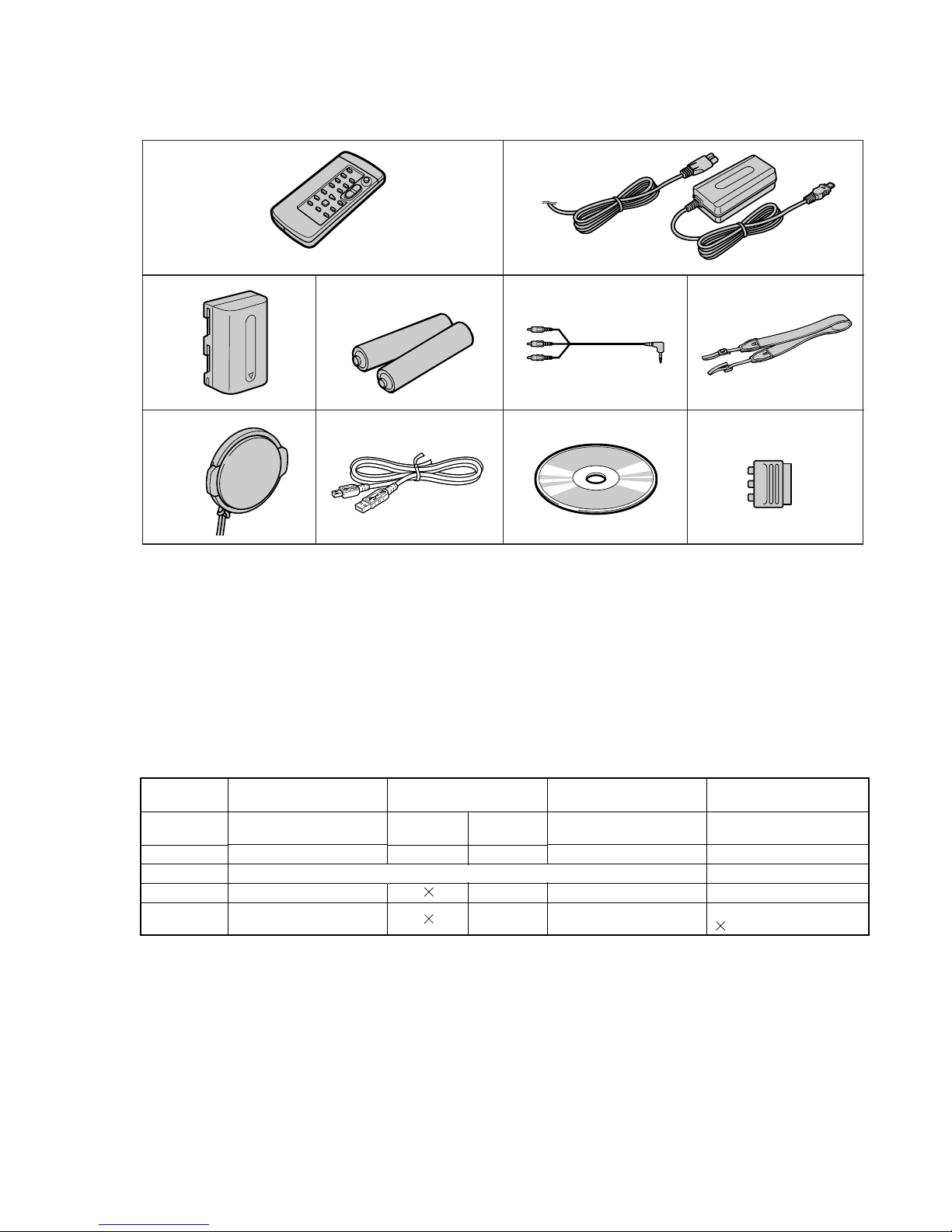
1 Wireless Remote Commander (1)
2 AC-L10A/L10B/L10C AC power adaptor (1)
Power cord (1)
3 NP-FM30 battery pack (1)
4 R6 (Size AA) battery for Remote
Commander (2)
5 A/V connecting cable (1)
6 Shoulder strap (1)
7 Lens cap (1)
8 USB Cable (1)
9
CD-ROM (SPVD-008 USB Driver) (1)
q; 21-pin adaptor
(1)

– 4 –
DCR-TRV140/TRV140E/TRV140M
TABLE OF CONTENTS
Section Title Page Section Title Page
SERVICE NOTE ................................................................... 6
1. Power Supply During Repairs....................................... 6
2. To Take Out a Cassette When Not Eject
(Force Eject).................................................................. 6
3. Note for Repair .............................................................. 7
4. LCD T ype Check............................................................ 7
SELF-DIAGNOSIS FUNCTION ........................................ 8
1. Self-diagnosis Function................................................. 8
2. Self-diagnosis Display................................................... 8
3. Service Mode Display ................................................... 8
3-1. Display Method.............................................................. 8
3-2. Switching of Backup No. ............................................... 8
3-3. End of Display ............................................................... 8
4. Self-diagnosis Code Table ............................................ 9
1. GENERAL
Checking Supplied Accessories.............................................. 1-1
Quick Start Guide .................................................................... 1-1
Using This Manual ................................................................... 1-2
Step 1 Preparing the Power Supply........................................ 1-2
Step 2 Setting the Data and Time........................................... 1-4
Step 3 Inserting a Cassette..................................................... 1-5
Recording a Picture................................................................. 1-5
Checking the Recording – END SEARCH.............................. 1-8
Playing Back a Tape ................................................................ 1-9
Viewing the Recording on TV.................................................. 1-10
Recording a Still Image on a Tape – Tape Photo Recording .. 1-11
Using the Wide Mode .............................................................. 1-12
Using the Fader Function........................................................ 1-12
Using Special Effects – Picture Effect..................................... 1-13
Using Special Effects – Digital Effect...................................... 1-14
Using the PROGRAM AE Function......................................... 1-14
Adjusting the Exposure Manually............................................ 1-15
Focusing Manually................................................................... 1-15
Interval Recording ................................................................... 1-16
Frame by Frame Recording – Cut Recording ......................... 1-17
Superimposing a Title.............................................................. 1-17
Making Y our Own Titles ........................................................... 1-18
Using the Built-in Light ............................................................ 1-18
Playing Back a Tape with Picture Effects................................ 1-19
Playing Back a Tape with Digital Effects ................................. 1-20
Enlarging Images Recorded on Tapes – Tape PB ZOOM ...... 1-20
Quickly Locating a Scene Using the Zero Set
Memory Function..................................................................... 1-21
Searching a Recording by Date – Date Search...................... 1-21
Searching for a Photo – Photo Search/Photo Scan ............... 1-22
Dubbing a Tape........................................................................ 1-22
Dubbing a Tape Easily – Easy Dubbing .................................. 1-23
Dubbing Only Desired Scenes – Digital Program Editing ...... 1-26
Viewing Images Using Your Computer
– USB Streaming (Windows Users Only) .............................. 1-29
Changing the Menu Settings................................................... 1-31
Types of Trouble and Their Solutions ...................................... 1-34
Self-diagnosis Display ............................................................. 1-35
Warning Indicators and Messages.......................................... 1-36
About Video Cassettes ............................................................ 1-36
Abut the "InfoLITHIUM" Battery Pack ..................................... 1-37
About i.Link.............................................................................. 1-38
Using Your Camcorder Abroad................................................ 1-38
Maintenance Information and Precautions ............................. 1-38
Identifying the Parts and Controls........................................... 1-41
2. DISASSEMBLY
2-1. LCD Assembly, PD-156 Board...................................... 2-2
2-2. VF Lens Assembly, VF-150 Board ................................ 2-3
2-3. Video Light and Front Panel Assembly......................... 2-4
2-4. Cabinet (L) Assembly .................................................... 2-4
2-5. Cassette Lid Assembly.................................................. 2-4
2-6. Cabinet (R) Assembly ................................................... 2-6
2-7. EVF Block ...................................................................... 2-6
2-8. Battery Panel Block ....................................................... 2-6
2-9. Lens Assembly .............................................................. 2-7
2-10. VC-273 Board................................................................ 2-8
2-11. FP-398 Flexible Board .................................................. 2-8
2-12. Control Switch Block (FK-2000).................................... 2-8
2-13. Circuit Boards Location ................................................. 2-10
2-14. Flexible Boards Location............................................... 2-11
3. BLOCK DIAGRAMS
3-1. Overall Block Diagram (1/5) .......................................... 3-1
3-2. Overall Block Diagram (2/5) .......................................... 3-3
3-3. Overall Block Diagram (3/5) .......................................... 3-5
3-4. Overall Block Diagram (4/5) .......................................... 3-7
3-5. Overall Block Diagram (5/5) .......................................... 3-9
3-6. Power Block Diagram (1/2) ........................................... 3-11
3-7. Power Block Diagram (2/2) ........................................... 3-13
4. PRINTED WIRING BOARDS AND
SCHEMATIC DIAGRAMS
4-1. Frame Schematic Diagrams.......................................... 4-3
Frame (1/2) Schematic Diagram................................... 4-3
Frame (2/2) Schematic Diagram................................... 4-5
4-2. Printed Wiring Boards and Schematic Diagram ........... 4-7
CD-353 Printed Wiring Board and
Schematic Diagram ....................................................... 4-7
LS-057, FP-228, FP-299, FP-300, FP-302, FP-301
Flexible Printed Wiring Boards and
Schematic Diagram ....................................................... 4-9
VC-273 Printed Wiring Board........................................ 4-11
VC-273 (CAMERA PROCESS)
Schematic Diagram ....................................................... 4-15
VC-273 (CAMERA Y/C PROCESS)
Schematic Diagram ....................................................... 4-17
VC-273 (LENS MOTOR DRIVE)
Schematic Diagram ....................................................... 4-19
VC-273 (DV SIGNAL PROCESS)
Schematic Diagram ....................................................... 4-21
VC-273 (DV INTERFACE) Schematic Diagram............ 4-23
VC-273 (DIGITAL REC/PB AMP)
Schematic Diagram ....................................................... 4-25
VC-273 (VIDEO OUT) Schematic Diagram.................. 4-27
VC-273 (HI CONTROL) Schematic Diagram ............... 4-29
VC-273 (CAMERA/MECHA CONTROL)
Schematic Diagram ....................................................... 4-31
VC-273 (MECHANISM CONTROL)
Schematic Diagram ....................................................... 4-33
VC-273 (DRUM/CAPSTAN MOTOR DRIVE)
Schematic Diagram ....................................................... 4-35
VC-273 (AUDIO PROCESS) Schematic Diagram........ 4-37
VC-273 (USB I/F), FP-399 Schematic Diagram ........... 4-39
FK2000, SS-2000,VC-273 (CONNECTOR), FP-398
Schematic Diagram ....................................................... 4-41
FP-398 Flexible Printed Wiring Board .......................... 4-43
VC-273 (DC IN, CHARGE) Schematic Diagram .......... 4-44
VC-273 (DC/DC CONVERTER)
Schematic Diagram ....................................................... 4-45
SI-033 Printed Wiring Board ......................................... 4-47
SI-033 Schematic Diagram ........................................... 4-49
PD-156 Printed Wiring Board........................................ 4-51
PR-10000, PD-156 (RGB DRIVER,
TIMING GENERATOR) Schematic Diagram ................ 4-55
PD-156 (LCD DRIVER, BACK LIGHT DRIVE)
Schematic Diagram ....................................................... 4-57
LB-073 Printed Wiring Board and
Schematic Diagram ....................................................... 4-59

– 5 –
DCR-TRV140/TRV140E/TRV140M
Section Title Page Section Title Page
VF-150 Printed Wiring Board ........................................ 4-60
VF-150 Schematic Diagram .......................................... 4-61
CF-2000 Schematic Diagram........................................ 4-63
4-3. Waveforms..................................................................... 4-65
4-4. Parts Location ............................................................... 4-68
5. ADJUSTMENTS
1. Before Starting Adjustment........................................... 5-1
1-1. Adjusting Items
when Replacing Main Parts and Boards ................. 5-2
5-1. Camera Section Adjustment ......................................... 5-4
1-1. Preparations Before Adjustment
(Camera Section) ..................................................... 5-4
1-1-1. List of Service Tools ................................................. 5-4
1-1-2. Preparations ............................................................. 5-5
1-1-3. Precaution ................................................................ 5-7
1. Setting the Switch .................................................... 5-7
2. Order of Adjustments ............................................... 5-7
3. Subjects.................................................................... 5-7
1-2. Initialization of 7, 8, C, D, E, F Page Data ............... 5-8
1-2-1. Initialization of 8, C, D Page Data............................ 5-8
1. Initializing the 8, C, D Page Data............................. 5-8
2. Modification of 8, C, D Page Data ........................... 5-8
3. 8 Page Table............................................................. 5-8
4. C Page Table ............................................................ 5-9
5. D Page Table ............................................................ 5-10
1-2-2. Initialization of 7, E, F Page Data ............................ 5-11
1. Initializing the 7, E, F Page Data ............................. 5-11
2. Modification of 7, E, F Page Data............................ 5-11
3. 7 Page Table............................................................. 5-11
4. E Page Table ............................................................ 5-12
5. F Page Table............................................................. 5-13
1-3. Camera System Adjustments .................................. 5-14
1. HALL Adjustment ..................................................... 5-14
2. Flange Back Adjustment
(Using the Minipattern Box) ..................................... 5-15
3. Flange Back Adjustment
(Using the Flange Back Adjustment Chart and
Subject More Than 500 m Away) ............................. 5-16
3-1. Flange Back Adjustment (1)..................................... 5-16
3-2. Flange Back Adjustment (2)..................................... 5-16
4. Flange Back Check .................................................. 5-17
5. Picture Frame Setting .............................................. 5-18
6. Color Reproduction Adjustment............................... 5-19
7. AWB & LV Standard Data Input ............................... 5-20
8. Auto White Balance Adjustment .............................. 5-21
9. Auto White Balance Check ...................................... 5-22
10. Angular Velocity Sensor Output Check and
Steady Shot Check .................................................. 5-23
1-4. Electronic Viewfinder System Adjustments ............. 5-24
1. RGB AMP Adjustment (VF-150 Board) ................... 5-25
2. Contrast Adjustment (VF-150 Board) ...................... 5-25
1-5. LCD System Adjustments ........................................ 5-26
1. VCO Adjustment (PD-156 Board)............................ 5-26
2. RGB AMP Adjustment (PD-156 Board)................... 5-27
3. Contrast Adjustment (PD-156 Board)...................... 5-27
4. COM AMP Adjustment (PD-156 Board) .................. 5-28
5. V-COM Adjustment (PD-156 Board)........................ 5-28
6. White Balance Adjustment (PD-156 Board) ............ 5-29
5-2. Mechanism Section Adjustment ................................... 5-30
2-1. Adjustment Remote Commander ............................ 5-30
2-2. How to Enter Record Mode Without Cassette......... 5-30
2-3. How to Enter Playback Mode Without Cassette...... 5-30
2-4. Tape Path Adjustment .............................................. 5-31
2-4-1. Preparations for Adjustment .................................... 5-31
2-4-2. Tape Path Adjustment .............................................. 5-32
2-4-3. No.7 Guide (TG7) Adjustment ................................. 5-33
2-4-4. CUE, REV Waveforms Check .................................. 5-33
2-5. Checks After Adjustments........................................ 5-33
2-5-1. Wavefo rm Build-up Check........................................ 5-33
2-5-2. Tape Path Check ...................................................... 5-33
5-3. Video Section Adjustment ............................................. 5-34
3-1. Preparations Before Adjustments ............................ 5-34
3-1-1. Equipment to Required ............................................ 5-34
3-1-2. Precautions on Adjusting ......................................... 5-35
3-1-3. Adjusting Connectors............................................... 5-36
3-1-4. Connecting the Equipment....................................... 5-36
3-1-5. Alignment T ape......................................................... 5-37
3-1-6. Input/output Level and Impedance .......................... 5-37
3-2. System Control System Adjustment ........................ 5-38
1. Initialization of 7, 8, C, D, E, F Page Data ............... 5-38
2. Node Unique ID No. Input........................................ 5-38
2-1. Input of Company ID ................................................ 5-38
2-2. Input of Serial No...................................................... 5-38
3-3. Servo and RF System Adjustments......................... 5-40
1. REEL FG Adjustment (VC-273 Board) .................... 5-40
2. CAP FG Duty Adjustment (VC-273 Board) ............. 5-40
3. PLL f0 & LPF f0 Pre-adjustment (VC-273 Board) ..... 5-41
4. Switching Position Adjustment (VC-273 Board)...... 5-42
5. AGC Center Level Adjustment (VC-273 Board) ...... 5-43
6. APC & AEQ Adjustment (VC-273 Board) ................ 5-44
7. PLL f0 & LPF f0 Final Adjustment
(VC-273 Board) ........................................................ 5-45
3-4. Video System Adjustments ...................................... 5-46
1. 27 MHz Origin Oscillation Adjustment
(VC-273 Board) ........................................................ 5-46
2. S VIDEO OUT Y Level Adjustment
(VC-273 Board) ........................................................ 5-46
3. S VIDEO OUT Chroma Level Adjustment
(VC-273 Board) ........................................................ 5-47
4. VIDEO OUT Y, Chroma Level Check
(VC-273 Board) ........................................................ 5-48
3-5. Audio System Adjustments ...................................... 5-49
1. Digital8 Playback Level Check................................. 5-49
5-4. Service Mode ................................................................ 5-50
4-1. Adjustment Remote Commander ............................ 5-50
1. Using the Adjustment Remote Commander ............ 5-50
2. Precautions Upon Using the Adjustment
Remote Commander ................................................ 5-50
4-2. Data Process............................................................ 5-51
4-3. Service Mode ........................................................... 5-52
1. Setting the Test Mode .............................................. 5-52
2. Emergence Memory Address .................................. 5-52
2-1. C Page Emergence Memory Address ..................... 5-52
2-2. EMG Code (Emergency Code) ................................ 5-53
2-3. MSW Code ............................................................... 5-54
3. Bit Value Discrimination ........................................... 5-55
4. Switch Check (1) ...................................................... 5-55
5. Switch Check (2) ...................................................... 5-55
6. Switch Check (3) ...................................................... 5-56
7. LED, LCD (Display Window) Check ......................... 5-56
8. Record of Use Check ............................................... 5-57
9. Record of Self-diagnosis Check .............................. 5-58
6. REPAIR PARTS LIST
6-1. Exploded Views ............................................................. 6-1
6-1-1. Front Panel Block ..................................................... 6-1
6-1-2. Cabinet (R) Block ..................................................... 6-2
6-1-3. LCD Block................................................................. 6-3
6-1-4. EVF Block................................................................. 6-4
6-1-5. Cabinet (L) and Battery Panel Blocks...................... 6-5
6-1-6. Lens Block................................................................ 6-6
6-1-7. Main Board Block ..................................................... 6-7
6-1-8. Cassette Compartment Assembly,
Drum Assembly ........................................................ 6-8
6-1-9. LS Chassis Block Assembly .................................... 6-9
6-1-10. Mechanical Chassis Block Assembly-1 ................... 6-10
6-1-11. Mechanical Chassis Block Assembly-2 ................... 6-11
6-2. Electrical Parts List ....................................................... 6-12
* The color reproduction frame is shown on page 235.
– 6 –
DCR-TRV140/TRV140E/TRV140M
SERVICE NOTE
1. POWER SUPPLY DURING REPAIRS
In this unit, about 10 seconds after power is supplied (8.4 V) to the
battery terminal the power is shut off so that the unit cannot operate.
This following two methods are available to pr event this. Take
note of which to use during repairs.
Method 1.
Use the DC IN terminal. (Use the AC power adaptor.)
Method 2.
T o supply power to the battery terminal, connect the servicing remote commander RM-95 to this set via the LANC jack of I/F unit
for LANC control (J-6082-521-A) and CPC jig connector (J-6082539-A), and set the HOLD switch to “ADJ” side.
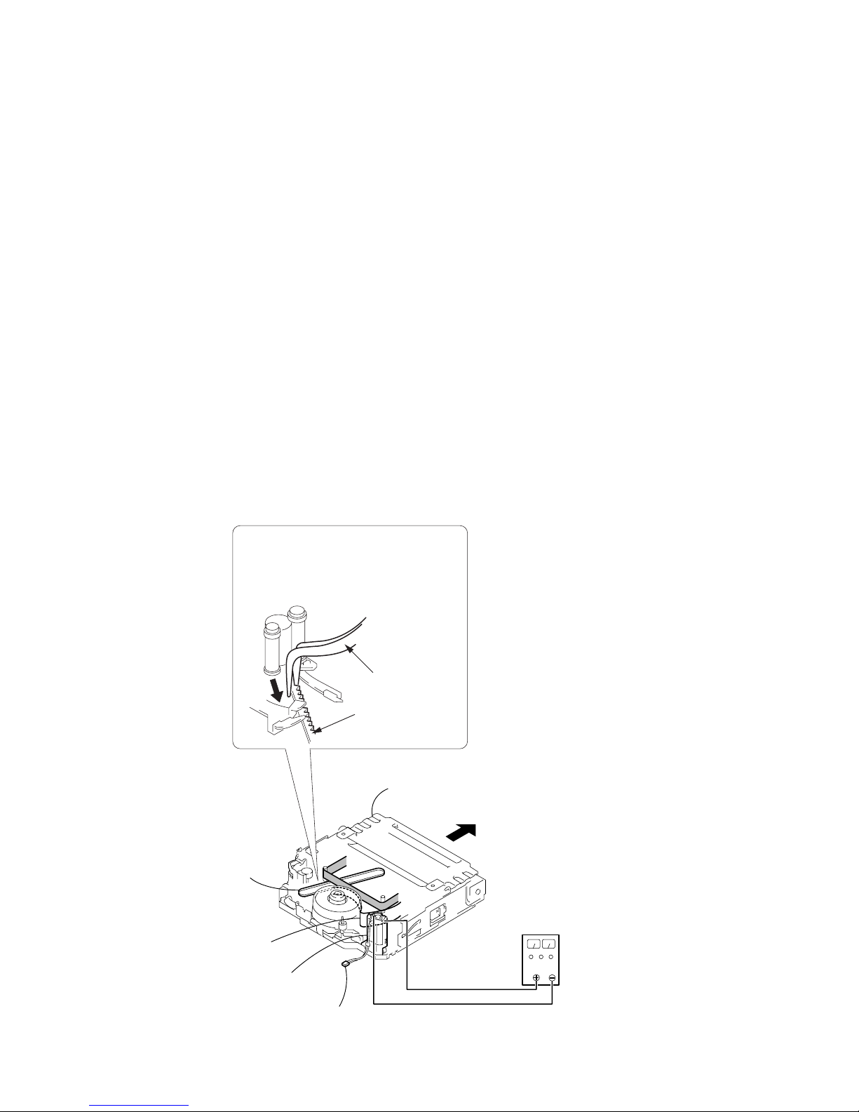
2. TO TAKE OUT A CASSETTE WHEN NOT
EJECT (FORCE EJECT)
1 Refer to 2-3. to remove the front panel section.
2 Refer to 2-4. to remove the cabinet (L) section.
3 Refer to 2-5. to remove the cabinet (R) section.
4 Open the control switch block (FK-2000).
5 Disconnect CN4401 (2P) of VC-273 board.
6 Add +5V from the DC POWER SUPPLY and unload with a
pressing the cassette compartment.
8 Let your hold the cassette
compartment and rise the cassette
compartment to take out a cassette.
DC power supply
(+5V)
Loading
motor
Adjust the bending
of a tape
Timing belt
Press the cassette compartment not
to rise the cassette compartment
Disconnect CN4401 of
VC-273 board
7 Pull the timing belt in the direction of
arrow A with a tweezers while pressing
the cassette compartment (take care
not to damage) to adjust the bending
of a tape.
Tweezers
Timing belt
A
Ver 1.1 2003. 06
– 7 –
DCR-TRV140/TRV140E/TRV140M
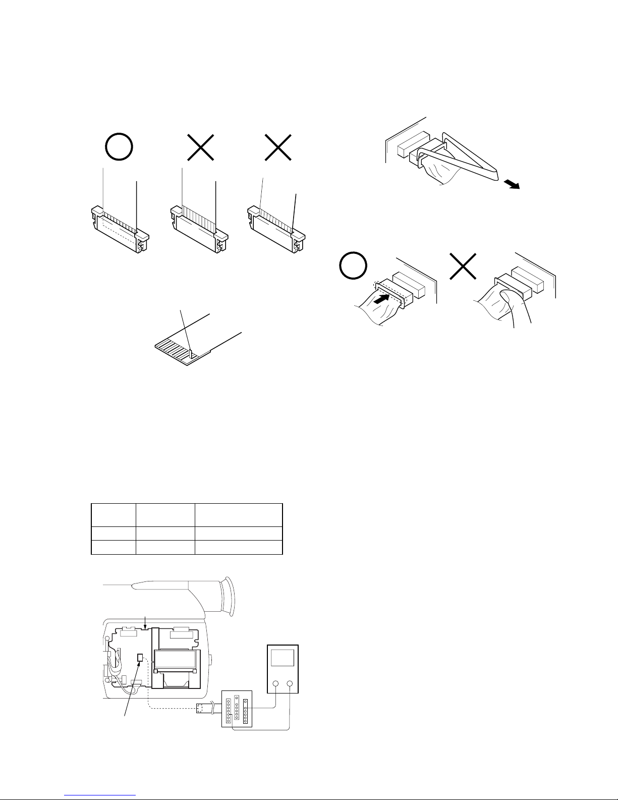
3. NOTE FOR REPAIR
Make sure that the flat cable and flexible board are not cracked of
bent at the terminal.
Do not insert the cable insufficiently nor crookedly.
When remove a connector, don’t pull at wire of connector.
It is possible that a wire is snapped.
Cut and remove the part of gilt
which comes off at the point.
(Be careful or some pieces of
gilt may be left inside)
When installing a connector, don’t press down at wire of connector.
It is possible that a wire is snapped.
4. LCD TYPE CHECK
By measuring the resistor value between Pin 6 of CN5502 and
Pin 0 of CN5502 on PD-156 board, the type of LCD can be discriminated.
Note: About PD-156 board and LCD module, discriminate LCD
type on the machine, and replace the same type.
PD-156 board CN5502
Resistor
LCD type PD board
value
1 kΩ TYPE S PD-156 (TYPE S)
1.5 kΩ TYPE C PD-156 (TYPE C)
Multi CPC jig
(J-6082-311-A)
PD-156 board
CN5502
6 pin
0 pin
Volt ohm meter
+
—
– 8 –
DCR-TRV140/TRV140E/TRV140M
SELF-DIAGNOSIS FUNCTION
1. Self-diagnosis Function
When problems occur while the unit is operating, the self-diagnosis function starts working, and displays on the viewfinder or Display window what to do. This function consists of two display;
self-diagnosis display and service mode display.
Details of the self-diagnosis functions are provided in the Instruction manual.
Note: The “self-diagnosis display” data will be backed up by the lithium batter y (CONTROL SWITCH BLOCK (CF-2000):
BT001). When removing the cabinet (R) (removing the VC-273 board CN1007), the “self-diagnosis display” data will
be lost by initialization.
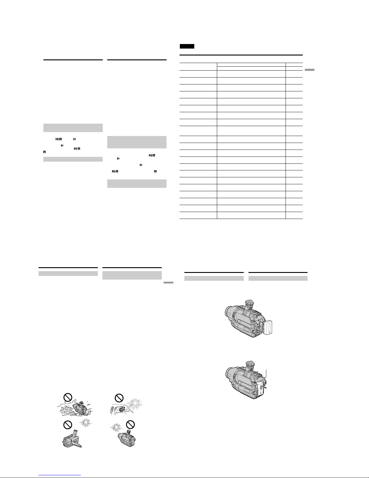
2. Self-diagnosis Display
When problems occur while the unit is operating, the counter of
the viewfinder or Display window sho ws a 4-digit display consisting of an alphabet and numbers, which blinks at 3.2 Hz. This 5character display indicates the “repaired by:”, “block” in which
the problem occurred, and “detailed code” of the problem.
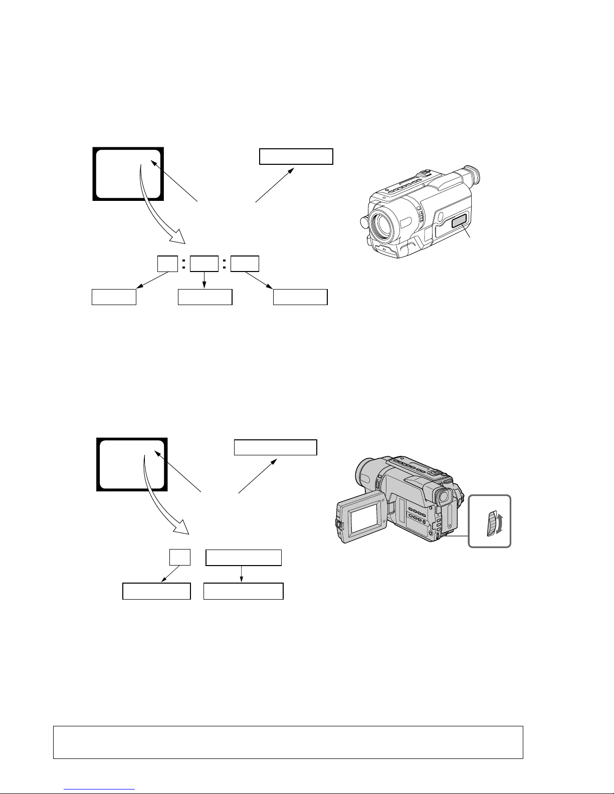
3. Service Mode Display
The service mode display shows up to six self-diagnosis codes shown in the past.
3-1. Display Method
While pressing the “STOP” key, set the switch from OFF to “VCR or PLAYER”, and continue pressing the “STOP” key for 5 seconds
continuously. The service mode will be displayed, and the counter will show the backup No. and the 5-character self-diagnosis codes.
3-2. Switching of Backup No.
By rotating the control dial, past self-diagnosis codes will be shown in order. The backup No. in the [] indicates the order in which the
problem occurred. (If the number of problems which occurred is less than 6, only the number of problems which occurred will be shown.)
[1] : Occurred first time [4] : Occurred fourth time
[2] : Occurred second time [5] : Occurred fifth time
[3] : Occurred third time [6] : Occurred the last time
3-3. End of Display
Turning OFF the power supply will end the service mode display.
Order of previous errors
Backup No.
Self-diagnosis Codes
C : 3 1 : 1 1
[3]
Lights up
Viewfinder
[3] C : 3 1 : 1 1
3 C : 3 1 : 11
Display window
1 1
3 1
C : 3 1 : 11
C
Repaired by:
Refer to page 9 and 10.
Self-diagnosis Code Table.
Indicates the appropriate
step to be taken.
E.g.
31 ....Reload the tape.
32 ....Turn on power again.
Block
Detailed Code
Blinks at 3.2Hz
C : Corrected by customer
H : Corrected by dealer
E : Corrected by service
engineer
Viewfinder Display window
C : 3 1 : 1 1
Display window
control dial

– 9 –
DCR-TRV140/TRV140E/TRV140M
4. Self-diagnosis Code Table
C
C
C
C
C
C
C
C
C
C
C
C
C
C
C
C
C
C
C
C
C
C
C
C
C
C
C
C
C
Block
Function
04
21
22
31
31
31
31
31
31
31
31
31
31
31
31
31
32
32
32
32
32
32
32
32
32
32
32
32
32
Detailed
Code
00
00
00
10
11
20
21
22
23
30
31
40
41
42
43
44
10
11
20
21
22
23
30
31
40
41
42
43
44
Symptom/State
Non-standard battery is used.
Condensation.
Video head is dirty.
LOAD direction. Loading does not
complete within specified time
UNLOAD direction. Loading does not
complete within specified time
T reel side tape slacking when unloading
.
S reel
side tape slacking when unloading
.
T reel fault.
S reel fault.
FG fault when starting capstan.
FG fault during normal capstan operations.
FG fault when starting drum.
PG fault when starting drum.
FG fault during normal drum operations.
PG fault during normal drum operations.
Phase fault during normal drum operations.
LOAD direction loading motor time-
out.
UNLOAD direction loading motor
time-out.
T reel side tape slacking when
unloading.
S reel side tape slacking when
unloading.
T reel fault.
S reel fault.
FG fault when starting capstan.
FG fault during normal capstan
operations.
FG fault when starting drum.
PG fault when starting drum.
FG fault during normal drum
operations.
PG fault during normal drum
operations.
Phase fault during normal drum
operations.
Self-diagnosis Code
Repaired by:
Correction
Use the InfoLITHIUM battery.
Remove the cassette, and insert it again after one hour.
Clean with the optional cleaning cassette.
Load the tape again, and perform operations from the beginning.
Load the tape again, and perform operations from the beginning.
Load the tape again, and perform operations from the beginning.
Load the tape again, and perform operations from the beginning.
Load the tape again, and perform operations from the beginning.
Load the tape again, and perform operations from the beginning.
Load the tape again, and perform operations from the beginning.
Load the tape again, and perform operations from the beginning.
Load the tape again, and perform operations from the beginning.
Load the tape again, and perform operations from the beginning.
Load the tape again, and perform operations from the beginning.
Load the tape again, and perform operations from the beginning.
Load the tape again, and perform operations from the beginning.
Remove the battery or power cable, connect, and perform
operations from the beginning.
Remove the battery or power cable, connect, and perform
operations from the beginning.
Remove the battery or power cable, connect, and perform
operations from the beginning.
Remove the battery or power cable, connect, and perform
operations from the beginning.
Remove the battery or power cable, connect, and perform
operations from the beginning.
Remove the battery or power cable, connect, and perform
operations from the beginning.
Remove the battery or power cable, connect, and perform
operations from the beginning.
Remove the battery or power cable, connect, and perform
operations from the beginning.
Remove the battery or power cable, connect, and perform
operations from the beginning.
Remove the battery or power cable, connect, and perform
operations from the beginning.
Remove the battery or power cable, connect, and perform
operations from the beginning.
Remove the battery or power cable, connect, and perform
operations from the beginning.
Remove the battery or power cable, connect, and perform
operations from the beginning.

– 10 –
DCR-TRV140/TRV140E/TRV140M
E
E
E
E
E
Block
Function
20
61
61
62
62
Detailed
Code
00
00
10
00
01
Symptom/State
EEPROM data error
Difficult to adjust focus
(Cannot initialize focus.)
Zoom operations fault
(Cannot initialize zoom lens.)
Handshake correction function does not
work well. (With pitch angular velocity
sensor output stopped.)
Handshake correction function does not
work well. (With yaw angular velocity
sensor output stopped.)
Self-diagnosis Code
Repaired by:
Correction
Initialize page data (EEPROM)
Inspect the lens block focus reset sensor (Pin qs of CN1551 of
VC-273 board) when focusing is performed when the control dial
is rotated in the focus manual mode and the focus motor drive circuit
(IC1551 of VC-273 board) when the focusing is not performed.
Inspect the lens block zoom reset sensor (Pin qf of CN1551 of
VC-273 board) when zooming is performed when the zoom lens is
operated and the zoom motor drive circuit (IC1551 of VC-273
board) when zooming is not performed.
Inspect pitch angular velocity sensor (SE750 of SI-033 board)
peripheral circuits.
Inspect yaw angular velocity sensor (SE751 of SI-033 board)
peripheral circuits.

1-1
DCR-TRV140/TRV140E/TRV140M
SECTION 1
GENERAL
This section is extracted from DCRTRV140E instruction manual.
2
Русский
Добро пожаловать!
Поздpaвляeм Bac c пpиобpeтeниeм
видeокaмepы Digital Handycam/Handycam
Vision
TM
фиpмы Sony. C помощью
видeокaмepы Digital Handycam/Handycam
Vision
TM
можно зaпeчaтлeть доpогиe Baм
мгновeния жизни c пpeвоcxодным кaчecтвом
изобpaжeния и звyкa.
Bидeокaмepa Digital Handycam/Handycam
Vision
TM
оcнaщeнa ycовepшeнcтвовaнными
фyнкциями, но в то жe вpeмя ee очeнь лeгко
иcпользовaть. Bcкоpe Bы бyдeтe cоздaвaть
ceмeйныe видeопpогpaммы, котоpыми
cможeтe нacлaждaтьcя в поcлeдyющиe годы.
ПРЕДУПРЕЖДЕНИЕ
Для предотвращения возгорания или
опасности электрического удара не
выставляйте аппарат на дождь или влагу.
Во избежание поражения электрическим
током не открывайте корпус.
За обслуживанием обращаться только к
квалифицированному обслуживающему
персоналу.
Для покупателей в Европе
ВНИМАНИЕ (только модeль
DCR-TRV140E)
Электромагнитные поля на определенных
частотах могут влиять на изображение и
звук, воcпpоизводимыe данной цифровой
видеокамеры.
Это изделие прошло проверку на
соответствие требованиям Директивы EMC
для использования соединительных кабелей
короче 3 метров.
English
Welcome!
Congratulations on your purchase of this Sony
Digital Handycam
camcorder/Handycam
Vision
TM
. With your Digital Handycam/
Handycam Vision
TM
, you can capture life’s
precious moments with superior picture and
sound quality.
Your Digital Handycam/Handycam Vision
TM
is
loaded with advanced features, but at the same
time it is very easy to use. You will soon be
producing home video that you can enjoy for
years to come.
WARNING
To prevent fire or shock hazard, do not expose
the unit to rain or moisture.
To avoid electrical shock, do not open the
cabinet.
Refer servicing to qualified personnel only.
NOTICE ON THE SUPPLIED AC POWER
ADAPTOR FOR THE CUSTOMERS IN
THE UNITED KINGDOM
A moulded plug complying with BS1363 is fitted
to this equipment for your safety and
convenience.
Should the fuse in the plug supplied need to
be replaced, a 5 AMP fuse approved by ASTA
or BSI to BS1362 (i.e., marked with
or
mark) must be used.
If the plug supplied with this equipment has a
detachable fuse cover, be sure to attach the
fuse cover after you change the fuse. Never
use the plug without the fuse cover. If you
should lose the fuse cover, please contact
your nearest Sony service station.
For the customers in Europe
ATTENTION (DCR-TRV140E only)
The electromagnetic fields at the specific
frequencies may influence the picture and sound
of this digital camcorder.
This product has been tested and found
compliant with the limits set out in the EMC
Directive for using connection cables shorter than
3 meters. (9.8 feet)
For the customers in Germany
(DCR-TRV140E only)
Directive:EMC Directive 89/336/EEC.
92/31/EEC
This equipment complies with the EMC
regulations when used under the following
circumstances:
•Residential area
•Business district
•Light-industry district
(This equipment complies with the EMC
standard regulations EN55022 Class B.)
CCD-TRV108E/TRV208E/TRV408E
5
1
Бecпpоводный пyльт диcтaнционного
yпpaвлeния (1) (стр. 197)*
1)
RMT-708: CCD-TRV107E/TRV208E/TRV408E
RMT-814: DCR-TRV140E
2
Ceтeвой aдaптep пepeмeнного токa
AC-L10A/L10B/L10C (1), пpовод
элeктpопитaния (1) (стр. 19)
3
Бaтapeйный блок NP-FM30 (1) (стр. 18, 19)
4
Бaтapeйкa R6 (paзмepa AA) для пyльтa
диcтaнционного yпpaвлeния (2) (стр. 198)*
1)
5
Cоeдинитeльный кaбeль ayдио/видeо (1)
(cтp. 50)
Mонофоничecкий: CCD-TRV107E/TRV108E/
TRV208E/TRV408E
Cтepeо: Tолько модeль DCR-TRV140E
6
Плeчeвой peмeнь (1) (стр. 192)
7
Кpышкa объeктивa (1) (стр. 29, 196)
8
Кaбeль USB (1) (cтp. 123)*
2)
9
CD-ROM (дpaйвep USB SPVD-008) (1)
(cтp. 125)*
2)
0
21-штыpьковый aдaптep (1) (cтp. 52)
(Tолько для eвpопeйcкиx модeлeй)
Проверка прилагаемых
принадлежностей
Убедитесь, что следующие принадлежности
прилагаются к Вашей видеокамере.
Содержание записи не может быть
компенсировано в случае, если запись или
воспроизведение не выполнены из-за
неисправности видеокамеры, носителя
информации и т.п.
*
1)
Tолько модeль CCD-TRV107E/TRV208E/
TRV408E, DCR-TRV140E
*
2)
Tолько модeль DCR-TRV140E
1
2
3
45
6
78
RMT-814
RMT-708
Monaural/
монофоничecкий
Stereo/
cтepeо
9
or/
или
q;
or/или
Contents of the recording cannot be
compensated if recording or playback is not
made due to a malfunction of the camcorder,
storage media, etc.
*
1)
CCD-TRV107E/TRV208E/TRV408E,
DCR-TRV140E only
*
2)
DCR-TRV140E only
Checking supplied
accessories
Make sure that the following accessories are
supplied with your camcorder.
1 Wireless Remote Commander (1) (p. 197)*
1)
RMT-708:CCD-TRV107E/TRV208E/TRV408E
RMT-814: DCR-TRV140E
2 AC-L10A/L10B/L10C AC power adaptor (1),
Mains lead (1) (p. 19)
3 NP-FM30 battery pack (1) (p. 18, 19)
4 R6 (Size AA) battery for Remote
Commander (2) (p. 198)*
1)
5 A/V connecting cable (1) (p. 50)
Monaural: CCD-TRV107E/TRV108E/
TRV208E/TRV408E
Stereo: DCR-TRV140E only
6 Shoulder strap (1) (p. 192)
7 Lens cap (1) (p. 29, 196)
8 USB Cable (1) (p. 123)*
2)
9
CD-ROM (SPVD-008 USB Driver) (1) (p. 125)*
2)
q; 21-pin adaptor (1) (p. 52) (European models
only)
10
Inserting a cassette
(p. 27)
English
Quick Start Guide
This chapter introduces you to the basic features of your
camcorder. See the page in parentheses “( )” for more
information.
Open the DC IN
jack cover.
Connect the plug with
its v mark facing up.
Connecting the mains lead
(p. 19)
Use the battery pack when using your camcorder outdoors (p. 18).
AC power adaptor (supplied)
Quick Start Guide
3
Close the cassette
compartment by
pressing the
mark
on the cassette
compartment. The
cassette compartment
automatically goes
down.
Close the lid of the
cassette compartment.
1
Open the lid of the
cassette compartment,
and press Z EJECT.
The cassette
compartment opens
automatically.
2
Insert a cassette
into the cassette
compartment
with its window
facing out and
the write-protect
tab on the
cassette up.
EJ
EC
T
11
Recording a picture
(p. 29)
2
Set the POWER
switch to CAMERA
while pressing the
small green button.
4
Press START/STOP.
Your camcorder
starts recording. To
stop recording, press
START/STOP again.
1
Remove the lens cap.
3
Open the LCD panel
while pressing OPEN.
The picture appears
on the LCD screen.
Viewfinder
When the LCD panel is closed, use the
viewfinder placing your eye against its eyecup.
The picture in the viewfinder is black and white.
Adjust the viewfinder lens to your eyesight (p. 34).
Quick Start Guide
Monitoring the playback picture on the LCD
screen
(p. 43)
NOTE
Do not pick up your camcorder by
the viewfinder, the LCD panel or the
battery pack.
2
Press m to rewind the tape.
3
Press N to start playback.
1
Set the POWER
switch to PLAYER
while pressing the
small green button.
When you purchase your camcorder, the clock setting is set to off. If you want to
record the date and time for a picture, set the clock setting before recording (p. 25).
C
A
M
E
R
A
P
L
A
Y
E
R
O
F
F
(
C
H
G
)
P
O
W
E
R
C
A
M
E
R
A
P
L
A
Y
E
R
O
F
F
(
C
H
G
)
P
O
WE
R
C
A
M
E
R
A
P
L
A
Y
E
R
O
F
F
(
C
H
G
)
P
O
W
E
R
PLAY
REW
1-2
DCR-TRV140/TRV140E/TRV140M
14
Инcтpyкции в дaнном pyководcтвe
пpeднaзнaчeны для пяти модeлeй,
пepeчиcлeнныx в тaблицe (cтp. 16). Прежде,
чем приступить к ознакомлению с данным
руководством и эксплуатации Вашей
видеокамеры, проверьте номер модели с
нижней стороны видеокамеры. Для
иллюстративных целей используется модель
DCR-TRV140E. В противном случае название
модели указывается на рисунках. Всякие
отличия в работе четко указываются в
тексте, например, “только модель
DCR-TRV140E”.
При чтении данного руководства учитывайте,
что кнопки и установки на видеокамере
показаны заглавными буквами.
Пpимep. Установите выключатель POWER в
положение CAMERA.
При выполнении операции на видеокамере
Вы сможете услышать зуммерный сигнал,
подтверждающий выполнение операции.
— Подготовка к эксплуатации —
Использование
данного руководства
Перед началом эксплуатации
Вашей видеокамеры (Только
модель DCR–TRV140E)
C этой видeокaмepой peкомeндyeтcя
иcпользовaть видeокacceты Hi8
/
Digital8
. Baшa видeокaмepa выполняeт
зaпиcь и воcпpоизвeдeниe изобpaжeний
только в cиcтeмe Digital8
. Heльзя
воcпpоизводить лeнты, зaпиcaнныe в cиcтeмe
Hi8
/cтaндapтной cиcтeмe 8 mm
(aнaлоговой).
Примечание по системам
цветного телевидения
Системы цветного телевидения отличаются в
зависимости от страны. Для просмотра Ваших
записей на экране телевизора Вам
необходимо использовать телевизор,
основанный на системе PAL.
— Getting started —
Using this manual
The instructions in this manual are for the five
models listed in the table below (p. 15). Before
you start reading this manual and operating your
camcorder, check the model number by looking
at the bottom of your camcorder. The
DCR-TRV140E is the model used for illustration
purposes. Otherwise, the model name is
indicated in the illustrations. Any differences in
operation are clearly indicated in the text, for
example, “DCR-TRV140E only.”
As you read through this manual, buttons and
settings on your camcorder are shown in capital
letters.
e.g. Set the POWER switch to CAMERA.
When you carry out an operation, you can hear a
beep sound to indicate that the operation is being
carried out.
Before using your camcorder
(DCR-TRV140E only)
With your digital camcorder, we recommend
using Hi8
/Digital8 video cassettes. Your
camcorder records and plays back pictures only
in the Digital8
system. You cannot play back
tapes recorded in the Hi8
/standard 8 mm
(analogue) system.
Note on TV colour systems
TV colour systems differ from country to
country. To view your recordings on a TV, you
need a PAL system-based TV.
15
Getting started Подготовка к эксплуатации
Types of differences
Model name
CCD- DCR-
TRV107E TRV108E TRV208E TRV408E TRV140E
System Hi8 Hi8 Hi8 Hi8 Digital8
Playback Hi8/8 Hi8/8 Hi8/8 Hi8/8 Digital8
Digital Zoom 450× 460× 560× 560× 560×
Remote Sensor z — zzz
Steadyshot — — — zz
Date and time zzzz—
DNR
zzzz—
(Digital Noise Reduction)
Easy Dubbing zzzz—
ORC
(Optimizing the Recording zzzz—
Condition)
TBC
zzzz—
(Time Base Corrector)
Data Code — — — — z
Digital effect — — — — z
Digital program editing — — — — z
DV OUT jack — — — — z
Frame recording — — — — z
Hifi SOUND — — — — z
Interval recording — — — — z
Super NightShot/
————z
Colour Slow Shutter
Tape Photo recording — — — — z
USB Streaming — — — — z
Zero set memory — — — — z
z Provided
— Not provided
English
Using this manual
17
Getting started Подготовка к эксплуатации
Использование данного
руководства
Меры предосторожности при
уходе за видеокамерой
Oбъeктив и экpaн ЖКД/видоиcкaтeль
(только нa монтиpyeмыx модeляx)
• Экран ЖКД и видоискатель изготовлены
с помощью высокопрецизионной
технологии, поэтому свыше 99,99%
элементов изображений предназначено
для эффективного использования.
Однако на экране ЖКД и в видоискателе
могут появляться маленькие черные и/
или яркие цветные точки (белые,
красные, синие или зеленые). Появление
этих точек вполне нормально для
процесса съемки и никоим образом не
влияет на записываемое изображение.
• Не допускайте, чтобы видеокамера
становилась влажной. Предохраняйте
видеокамеру от дождя и морской воды.
Если Вы намочите видеокамеру, то это может
привести к неисправности аппарата, которая
не всегда может быть устранена [a].
• Никогда не оставляйте видеокамеру в
месте с температурой выше 60°С, как,
например, в автомобиле, оставленном на
солнце или под прямым солнечным светом
[b].
• Будьте осторожны при размещении
видеокамеры возле окна или вне
помещения. Воздействие прямого
солнечного света на экран ЖКД,
видоискатель или объектив в течение
длительного периода времени может
привести к неисправностям. [c].
• Не направляйте камеру прямо на солнце.
Это может привести к неисправности
Вашей видеокамеры. Проводите съемки
солнца в условиях низкой освещенности,
таких, как сумерки [d].
Precautions on camcorder care
Lens and LCD screen/finder
(on mounted models only)
•The LCD screen and the finder are
manufactured using extremely highprecision technology so over 99.99% of the
pixels are operational for effective use.
However, there may be some tiny black
points and/or bright points (white, red, blue
or green in colour) that constantly appear on
the LCD screen and the finder. These points
are normal in the manufacturing process and
do not affect the recording in any way.
•Do not let your camcorder get wet. Keep your
camcorder away from rain and sea water.
Letting your camcorder get wet may cause your
camcorder to malfunction. Sometimes this
malfunction cannot be repaired [a].
•Never leave your camcorder exposed to
temperatures above 60°C (140°F), such as in a
car parked in the sun or under direct sunlight
[b].
•Be careful when placing the camera near a
window or outdoors. Exposing the LCD screen,
the finder or the lens to direct sunlight for long
periods may cause malfunctions. [c].
•Do not directly shoot the sun. Doing so might
cause your camcorder to malfunction. Take
pictures of the sun in low light conditions such
as dusk [d].
Using this manual
[a] [b]
[d][c]
18
Пункт 1
Подготовка
источника питания
Установка батарейного блока
Передвиньте батарейный блок вниз, так
чтобы он защелкнулся на месте.
Для cнятия бaтapeйного блокa
Пepeдвиньтe бaтapeйный блок в нaпpaвлeнии
cтpeлки, нaжaв кнопкy V BATT вниз.
V BATT release lever/
Рычаг для снятия
батарейного блокa V BATT
Installing the battery pack
Slide the battery pack down until it clicks.
To remove the battery pack
Slide the battery pack out in the direction of the
arrow while pressing V BATT down.
Step 1 Preparing the
power supply

1-3
DCR-TRV140/TRV140E/TRV140M
19
Getting started Подготовка к эксплуатации
4
2,3
1
C
A
M
E
R
A
O
F
F
(
C
H
G
)
POWER
FULL
P
L
A
Y
E
R
Пункт 1 Подготовка источника
питания
Зарядка батарейного блока
Иcпользyйтe бaтapeйный блок для Baшeй
видeокaмepы поcлe eго зapядки.
Baшa видeокaмepa paботaeт только c
бaтapeйным блоком “InfoLITHIUM” (cepии M).
Подpобныe cвeдeния о бaтapeйном блокe
“InfoLITHIUM” пpивeдeны нa cтp. 174.
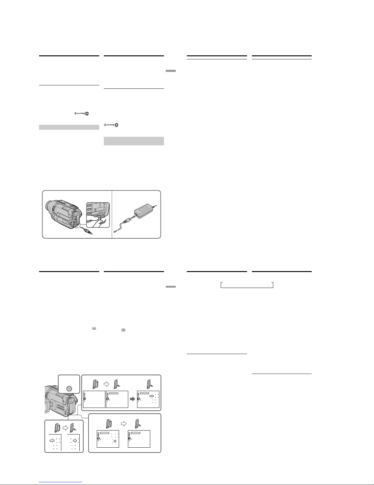
(1)Oткpойтe кpышкy гнeздa DC IN и
подcоeдинитe ceтeвой aдaптep пepeмeнного
токa, пpилaгaeмый к Baшeй видeокaмepe, к
гнeздy DC IN, тaк чтобы штeкep v был
нaпpaвлeн ввepx.
(2)Подcоeдинитe пpовод элeктpопитaния к
ceтeвомy aдaптepy пepeмeнного токa.
(3)Подcоeдинитe пpовод элeктpопитaния к
ceтeвой pозeткe.
(4)Уcтaновитe пepeключaтeль POWER в
положeниe OFF (CHG). Haчнeтcя зapядкa. B
окошкe диcплeя бyдeт отобpaжaтьcя вpeмя
оcтaвшeгоcя зapядa в минyтax.
Ecли индикaтоp оcтaвшeгоcя зapядa
измeнитcя нa
, это знaчит, что
ноpмaльнaя зapядкa зaвepшeнa. Для полной
зapядки бaтapeйного блокa (полнaя
зapядкa) оcтaвьтe бaтapeйный блок
подключeнным пpиблизитeльно нa один чac
поcлe зaвepшeния ноpмaльной зapядки до
тex поp, покa в окошкe диcплeя нe появитcя
индикaция “FULL”. Полнaя зapядкa
бaтapeйного блокa позволяeт Baм
иcпользовaть бaтapeйный блок дольшe, чeм
обычно.
Чиcло нa pиcyнкe окошкa диcплeя можeт
отличaтьcя от чиcлa, котоpоe отобpaжaeтcя
нa видeокaмepe.
Step 1 Preparing the power
supply
Charging the battery pack
Use the battery pack after charging it for your
camcorder.
Your camcorder operates only with the
“InfoLITHIUM” battery pack (M series).
See page 174 for details of the “InfoLITHIUM”
battery pack.
(1)Open the DC IN jack cover and connect the
AC power adaptor supplied with your
camcorder to the DC IN jack with the plug’s v
mark facing up.
(2)Connect the mains lead to the AC power
adaptor.
(3)Connect the mains lead to a wall socket.
(4)Set the POWER switch to OFF (CHG).
Charging begins. The remaining battery time
is indicated in minutes on the display
window.
When the remaining battery indicator changes to
, normal charge is completed. To fully charge
the battery (full charge), leave the battery pack
attached for about one hour after normal charge
is completed until “FULL” appears in the display
window. Fully charging the battery allows you to
use the battery longer than usual.
The number in the illustration of the display
window may differ from that on your camcorder.
20
Пункт 1 Подготовка источника
питания
После зарядки батарейного блока
Отсоедините сетевой адаптер переменного
тока от гнезда DC IN на Вашей видеокамере.
Пpимeчaниe
He допycкaйтe контaктa мeтaлличecкиx
пpeдмeтов c мeтaлличecкими чacтями штeкepa
поcтоянного токa ceтeвого aдaптepa. Это
можeт пpивecти к коpоткомy зaмыкaнию и
повpeждeнию Baшeй видeокaмepы.
Индикaтоp оcтaвшeгоcя зapядa бaтapeйного
блокa
Oтобpaжaeтcя оcтaвшeecя вpeмя paботы
бaтapeи пpи cъeмкe c видоиcкaтeлeм.
Индикaтоp вpeмeни оcтaвшeгоcя зapядa
бaтapeйного блокa в окошкe диcплeя
пpиблизитeльно yкaзывaeт вpeмя зaпиcи c
иcпользовaниeм видоиcкaтeля.
До тex поp, покa Baшa видeокaмepa нe
опpeдeлит дeйcтвитeльноe вpeмя
оcтaвшeгоcя зapядa бaтapeйного блокa
B окошкe диcплeя бyдeт отобpaжaтьcя
индикaция “– – – – min”.
Bо вpeмя зapядки бaтapeйного блокa в
окошкe диcплeя нe бyдeт отобpaжaтьcя
индикaтоp, или он бyдeт мигaть в
cлeдyющиx cлyчaяx:
– Oтcоeдинeн ceтeвой aдaптep пepeмeнного
токa.
– Бaтapeйный блок ycтaновлeн нeпpaвильно.
– Heисправность бaтapeйного блокa.
Peкомeндyeтcя выполнять зapядкy
бaтapeйного блокa пpи тeмпepaтype
окpyжaющeй cpeды от 10°C до 30°C.
Ecли питaниe отключaeтcя, нecмотpя нa то,
что индикaтоp оcтaвшeгоcя вpeмeни paботы
бaтapeи покaзывaeт, что в нeй оcтaлcя
доcтaточный зapяд для ee
фyнкциониpовaния
Cновa полноcтью зapядитe бaтapeйный блок,
чтобы индикaтоp пpaвильно покaзывaл
оcтaвшeecя вpeмя paботы бaтapeи.
After charging the battery pack
Disconnect the AC power adaptor from the DC
IN jack on your camcorder.
Note
Prevent metallic objects from coming into contact
with the metal parts of the DC plug of the AC
power adaptor. This may cause a short-circuit,
damaging the AC power adaptor.
Remaining battery time indicator
The remaining battery time you record with the
viewfinder is displayed.
The remaining battery time indicator in the
display window roughly indicates the recording
time with the viewfinder.
Until your camcorder calculates the actual
remaining battery time
“– – – – min” appears in the display window.
While charging the battery pack, no indicator
appears or the indicator flashes in the display
window in the following cases:
– The AC power adaptor is disconnected.
– The battery pack is not installed properly.
– Something is wrong with the battery pack.
We recommend charging the battery pack in
an ambient temperature of between 10°C to
30°C (50°F to 86°F.)
If the power goes off although the battery
remaining indicator indicates that the battery
pack has enough power to operate
Charge the battery pack fully again so that the
indication on the battery remaining indicator is
correct.
Step 1 Preparing the power
supply
21
Getting started Подготовка к эксплуатации
Пункт 1 Подготовка источника
питания
Приблизительное время в минутах при
использовании полностью заряженного
батарейного блока
Пpиблизитeльноe вpeмя в минyтax для
зapядки полноcтью paзpяжeнного
бaтapeйного блокa пpи 25°C
Step 1 Preparing the power
supply
Charging time/Время зарядки
Battery pack/ Full charge (normal charge)/
Бaтapeйный блок Полнaя зapядкa (ноpмaльнaя зapядкa)
NP-FM30
145 (85)
(supplied)
/
(прилагается)
NP-FM50 150 (90)
NP-FM70 240 (180)
NP-QM71 260 (200)
NP-FM90 330 (270)
NP-FM91/QM91 360 (300)
Approximate number of minutes to charge an
empty battery pack at 25°C (77°F)
Recording time/Время записи
CCD-TRV107E/TRV108E/TRV208E/TRV408E
Recording with Recording with
the viewfinder/ the LCD screen/
Battery pack/ Запись с помощью Запись с помощью
Батарейный видоискателя экрана ЖКД
блок
Continuous*/ Typical**/ Continuous*/ Typical**/
Непрерывная* Типичная** Непрерывная* Типичная**
NP-FM30
165 90 120 65
(supplied)/(прилагается)
NP-FM50 265 145 195 105
NP-FM70 540 295 400 220
NP-QM71 640 350 465 255
NP-FM90 820 450 600 330
NP-FM91/QM91 955 525 695 380
DCR-TRV140E
Recording with Recording with
the viewfinder/ the LCD screen/
Battery pack/ Запись с помощью Запись с помощью
Батарейный видоискателя экрана ЖКД
блок
Continuous*/ Typical**/ Continuous*/ Typical**/
Непрерывная* Типичная** Непрерывная* Типичная**
NP-FM30
110 60 85 45
(supplied)/(прилагается)
NP-FM50 180 100 140 75
NP-FM70 370 205 295 160
NP-QM71 430 235 340 185
NP-FM90 560 310 450 245
NP-FM91/QM91 645 355 520 285
Approximate number of minutes when you use a
fully charged battery pack
22
* Приблизительное время непрерывной
записи при температуре 25°С. При
использовании видеокамеры в холодных
условиях срок службы батарейного блока
будет короче.
** Приблизительное время в минутах при
записи с неоднократным пуском/
остановкой записи, наездом видеокамеры
и включением/выключением питания.
Фактический срок службы заряда
батарейного блока может быть короче.
Пункт 1 Подготовка источника
питания
Приблизительное время в минутах при
использовании полностью заряженного
батарейного блока
Step 1 Preparing the power
supply
Playing time/Время воспроизведения
CCD-TRV107E/TRV108E/TRV208E/TRV408E
Playing time Playing time
Battery pack/
on LCD screen/ with LCD closed/
Батарейный
Время воспроизведения Время воспроизведения
блок
на экране ЖКД при закрытом ЖКД
NP-FM30
120 175
(supplied)/(прилагается)
NP-FM50 195 280
NP-FM70 400 570
NP-QM71 465 675
NP-FM90 600 865
NP-FM91/QM91 695 1010
DCR-TRV140E
Playing time Playing time
Battery pack/
on LCD screen/ with LCD closed/
Батарейный
Время воспроизведения Время воспроизведения
блок
на экране ЖКД при закрытом ЖКД
NP-FM30
85 115
(supplied)/(прилагается)
NP-FM50 140 185
NP-FM70 295 385
NP-QM71 340 445
NP-FM90 450 580
NP-FM91/QM91 520 670
Approximate number of minutes when you use a
fully charged battery pack
* Approximate continuous recording time at
25°C (77°F). The battery life will be shorter if
you use your camcorder in a cold
environment.
** Approximate number of minutes when
recording while you repeat recording start/
stop, zooming and turning the power on/off.
The actual battery life may be shorter.
1-4
DCR-TRV140/TRV140E/TRV140M
23
Getting started Подготовка к эксплуатации
2,3
1
Пpиблизитeльноe вpeмя нeпpepывного
воcпpоизвeдeния пpи 25°С.
При использовании видеокамеры в холодных
условиях срок службы батарейного блока
будет короче.
Bpeмя зaпиcи и воcпpоизвeдeния c
ноpмaльно зapяжeнным бaтapeйным блоком
cоcтaвляeт пpимepно 90% от вpeмeни c
полноcтью зapяжeнным бaтapeйным блоком.
Что такое “InfoLITHIUM”?
“InfoLITHIUM” представляет собой литиевоионный батарейный блок, который может
обмениваться данными, такими как
потребление заряда батарейного блока, с
совместимой электронной аппаратурой. Это
ycтpойcтво cовмecтимо c бaтapeйным блоком
“InfoLITHIUM” (cepии M). Baшa видeокaмepa
paботaeт только c бaтapeйным блоком
“InfoLITHIUM”. Ha бaтapeйныx блокax
“InfoLITHIUM” cepии M имeeтcя мeткa
.
“InfoLITHIUM” является торговой маркой
корпорации Sony Corporation.
Подсоединение к сетевой
розетке
Если Вы собираетесь использовать
видеокамеру длительное время,
рекомендуется использовать питание от
электрической сети с помощью сетевого
адаптера переменного тока.
(1)Откройте крышку гнезда DC IN и
подсоедините сетевой адаптер
переменного тока к гнезду DC IN на Вашей
видeокaмepe, так чтобы знак v на
штекере был обращен вверх.
(2)Подсоедините провод электропитания к
сетевому адаптеру переменного тока.
(3)Подсоедините провод электропитания к
сетевой розетке.
Пункт 1 Подготовка источника
питания
Step 1 Preparing the power
supply
Approximate continuous playing time at 25°C
(77°F).
The battery life will be shorter if you use your
camcorder in a cold environment.
The recording and playing time of a normally
charged battery are about 90% of those of a fully
charged battery.
What is the ”InfoLITHIUM”?
The “InfoLITHIUM” is a lithium ion battery pack
which can exchange data such as battery
consumption with compatible electronic
equipment. This unit is compatible with the
“InfoLITHIUM” battery pack (M series). Your
camcorder operates only with the
“InfoLITHIUM” battery pack. “InfoLITHIUM” M
series battery packs have the
mark.
“InfoLITHIUM” is a trademark of Sony
Corporation.
Connecting to a wall socket
When you use your camcorder for a long time,
we recommend that you power it from a wall
socket using the AC power adaptor.
(1)Open the DC IN jack cover, and connect the
AC power adaptor to the DC IN jack on your
camcorder with the plug’s v mark facing up.
(2)Connect the mains lead to the AC power
adaptor.
(3)Connect the mains lead to a wall socket.
24
Пункт 1 Подготовка источника
питания
ПРЕДОСТЕРЕЖЕНИЕ
Aппapaт не отключается от источника
переменного тока до тех пор, пока он
подсоединен к электрической сети, даже
если сам аппарат выключен.
Примечания
• Питание от сетевого адаптера переменного
тока может подаваться даже в случае, если
батарейный блок прикреплен к Вашей
видеокамере.
• Гнeздо DC IN облaдaeт “пpиоpитeтом
иcточникa”. Это ознaчaeт, что питaниe от
бaтapeйного блокa нe подaeтcя, покa
пpовод элeктpопитaния подcоeдинeн к
гнeздy DC IN, дaжe ecли пpовод
элeктpопитaния нe включeн в cтeннyю
pозeткy.
• Разместите сетевой адаптер переменного
тока возле электросети. При использовании
сетевого адаптера переменного тока в
случае неисправности данного аппарата
отсоедините штекер от электросети как
можно быстрее для отключения питания.
Использование автомобильного
аккумулятора
Иcпользyйтe aдaптep/зapядноe ycтpойcтво
поcтоянного токa Sony (пpиобpeтaeтcя
дополнитeльно). Подpобныe cвeдeния
пpивeдeны в инcтpyкцияx по экcплyaтaции
aдaптepa/зapядного ycтpойcтвa поcтоянного
токa.
Step 1 Preparing the power
supply
PRECAUTION
The set is not disconnected from the AC power
source (wall socket) as long as it is connected to a
wall socket, even if the set itself has been turned
off.
Notes
•The AC power adaptor can supply power even
if the battery pack is attached to your
camcorder.
•The DC IN jack has “source priority”. This
means that the battery pack cannot supply any
power if the mains lead is connected to the DC
IN jack, even when the mains lead is not
plugged into the wall socket.
•Place the AC power adaptor near the wall
socket. While using the AC power adaptor, if
any trouble occurs with this unit, disconnect the
plug from the wall socket as soon as possible to
cut off the power.
Using a car battery
Use Sony DC Adaptor/Charger (optional). Refer
to the operating instructions of the DC adaptor/
charger for further information.
25
Getting started Подготовка к эксплуатации
2
4
1,7
3
6
MENU
CLOCK SET
[
MENU
] :
END
SETUP MENU
CLOCK SET
LTR SIZE
LANGUAGE
DEMO MODE
SETUP MENU
––
:––:
––
RETURN
[
MENU
] :
END
SETUP MENU
000
[
MENU
] :
END
RETURN
SETUP MENU
[
MENU
] :
END
RETURN
CLOCK SET
SETUP MENU
[
MENU
] :
END
RETURN
CLOCK SET
LTR SIZE
DEMO MODE
CLOCK SET
LTR SIZE
DEMO MODE
112002
1
7:30:00
7
42002
17 30
112002
000
LTR SIZE
DEMO MODE
LTR SIZE
DEMO MODE
4 7 2002
LANGUAGE
LANGUAGE
LANGUAGE
LANGUAGE
USB S TREAM
USB S TREAM
USB S TREAM
USB S TREAMUSB STREAM
112002
000
Пункт 2 Установка даты
и времени
Если Вы используете свою видеокамеру впервые,
выполните установки даты и времени.
Покa нe бyдeт пpоизвeдeнa ycтaновкa дaты и
вpeмeни, кaждый paз пpи пepeводe
пepeключaтeля POWER в положeниe CAMERA
бyдeт отобpaжaтьcя индикaция “CLOCK SET”.
Ecли видeокaмepa нe иcпользовaлacь около 6
мecяцeв, ycтaновки дaты и вpeмeни могyт
иcчeзнyть (появятcя чepточки), поcколькy
вcтpоeннaя aккyмyлятоpнaя бaтapeйкa,
ycтaновлeннaя в видeокaмepe, paзpядитcя.
(1) Когдa видeокaмepa нaxодитcя в peжимe
CAMERA, нaжмитe кнопкy MENU для
отобpaжeния мeню.
(2) Поверните диск SEL/PUSH EXEC для выбора
индикации
, а затем нажмите диск.
(3) Поверните диск SEL/PUSH EXEC для выбора
команды CLOCK SET, а затем нажмите диск.
(4) Поверните диск SEL/PUSH EXEC для выбора
нужного года, а затем нажмите диск.
(5) Установите месяц, день и час путем
вращения диска SEL/PUSH EXEC и
нaжaтия
диска.
(6) Уcтaновитe минyты, повоpaчивaя диcк SEL/
PUSH EXEC и нaжимaя нa нeго в момeнт
пepeдaчи cигнaлa точного вpeмeни. Чacы
нaчнyт paботaть.
(7) Нажмите кнопку MENU для того, чтобы
исчезли установки меню.
Step 2 Setting the
date and time
Set the date and time settings when you use your
camcorder for the first time.
“CLOCK SET” will be displayed each time when
you set the power switch to CAMERA unless you
set the date and time settings.
If you do not use your camcorder for about 6
months, the date and time settings may be
released (bars may appear) because the built-in
rechargeable battery in your camcorder will have
been discharged.
First, set the year, then the month, the day, the
hour and then the minute.
(1)While your camcorder is in CAMERA mode,
press MENU to display the menu.
(2)Turn the SEL/PUSH EXEC dial to select
,
then press the dial.
(3)Turn the SEL/PUSH EXEC dial to select
CLOCK SET, then press the dial.
(4)Turn the SEL/PUSH EXEC dial to adjust the
desired year, then press the dial.
(5)Set the month, day and hour by turning the
SEL/PUSH EXEC dial and pressing the dial.
(6)Set the minute by turning the SEL/PUSH
EXEC dial and pressing the dial by the time
signal. The clock starts to operate.
(7)Press MENU to make the menu disappear.
The time indicator appears.
26
Год изменяется следующим образом:
Для проверки предварительно
установленных даты и времени
(Tолько модель CCD-TRV107E/
TRV108E/TRV208E/TRV408E)
Нажмите кнопку DATE для отображения
индикатора даты.
Нажмите кнопку TIME для отображения
индикатора времени.
Нажмите кнопку DATE (или TIME), а затем
нажмите кнопку TIME (или DATE) для
одновременного отображения индикатора
даты и времени.
Нажмите еще раз кнопку DATE и/или TIME.
Индикатор даты и/или времени исчезнет.
Функция автоматической даты
Пpи пepвом иcпользовaнии видeокaмepы
включитe ee и выполнитe ycтaновкy дaты и
вpeмeни в cоотвeтcтвии cо cвоим чacовым
пояcом пepeд нaчaлом зaпиcи (cтp. 25). Дaтa
будет автоматически записываться в течение
10 секунд после начала записи (функция
автоматической даты). Эта функция
работает один раз в день.
Примечание по индикатору времени
Встроенные часы Вашей видеокамеры
работают в 24-часовом режиме.
Примечание по функции автоматической
даты (Tолько модель CCD-TRV107E/
TRV108E/TRV208E/TRV408E)
Вы можете изменять установку AUTO DATE
путем выбора положений ON или OFF в
установках меню. Функция автоматической
даты автоматически отбражает дату один
раз в день.
Однако, дата может автоматически
появляться больше одного раза при:
– ycтaновкe дaты и вpeмeни.
– выталкивании и установке ленты обратно
на место.
– остановке записи в пределах 10 секунд.
– установке команды AUTO DATE в
положение OFF и возвращении в
положение ON в установках меню.
Пункт 2 Установка даты и времени
t 1995 T
. . . .
t 2002 T
. . . .
t 2079 T
The year changes as follows:
To check the preset date and time
(CCD-TRV107E/TRV108E/TRV208E/
TRV408E only)
Press DATE to display the date indicator.
Press TIME to display the time indicator.
Press DATE (or TIME) and then press TIME (or
DATE) to simultaneously display the date and
time indicator.
Press DATE and/or TIME again. The date and/
or time indicator disappears.
Auto date function
When you use your camcorder for the first time,
turn it on and set the date and time to your local
time before you start recording (p. 25). The date
is automatically recorded for 10 seconds after
you start recording (Auto date function). This
function works only once a day.
Note on the time indicator
The internal clock of your camcorder operates on
a 24-hour cycle.
Note on the auto date function
(CCD-TRV107E/TRV108E/TRV208E/TRV408E
only)
You can change the AUTO DATE setting by
selecting ON or OFF in the menu settings. The
auto date function automatically displays the
date once a day.
However, the date may automatically appear
more than once a day if:
– you set the date and time.
– you eject and insert the tape again.
– you stop recording within 10 seconds.
– you set AUTO DATE to OFF once and set it
back to ON in the menu settings.
Step 2 Setting the date and time
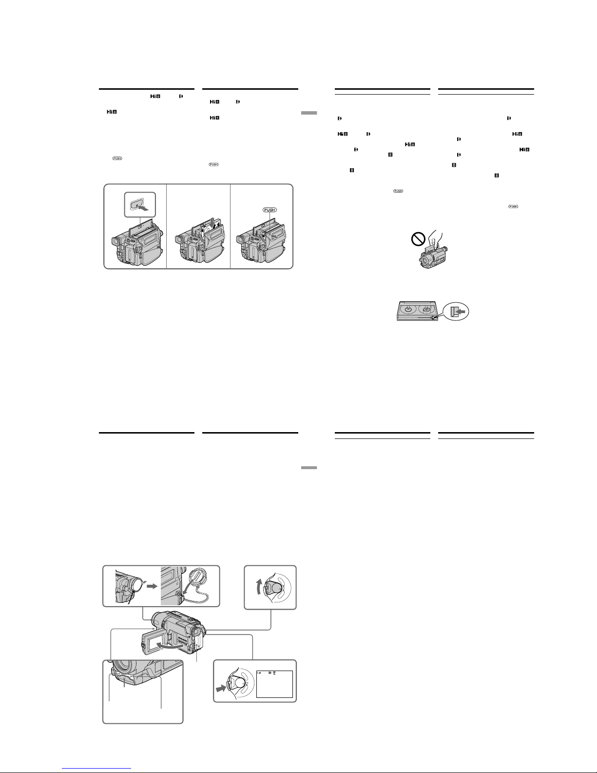
1-5
DCR-TRV140/TRV140E/TRV140M
27
Getting started Подготовка к эксплуатации
Пункт 3 Установка
кассеты
Peкомeндyeтcя иcпользовaть видeокacceты
Hi8
/Digital8 .*
1)
Ecли нeобxодимо выполнить зaпиcь в
cиcтeмe Hi8, пользyйтecь видeокacceтaми
Hi8
.*
2)
(1)Подготовьтe иcточник питaния (cтp. 18).
(2)Oткpойтe кpышкy кacceтного отceкa, a
зaтeм нaжмитe кнопкy Z EJECT. Кacceтный
отceк откpоeтcя aвтомaтичecки.
(3)Bcтaвьтe кacceтy в кacceтный отceк,
чтобы окошко было обpaщeно нapyжy, a
лeпecток зaщиты от зaпиcи - ввepx.
(4)Закройте кассетный отсек, нажав метку
на отсеке. Кассетный отсек
автоматически закроется.
(5)Закройте крышку кассетного отсека.
E
J
E
CT
2 3
4
We recommend using Hi8 /Digital8
video cassettes.*
1)
When you want to record in the Hi8 system, use
Hi8
video cassettes.*
2)
(1)Prepare the power supply (p. 18).
(2)Open the lid of the cassette compartment, and
press Z EJECT. The cassette compartment
opens automatically.
(3)Insert a cassette into the cassette compartment
with its window facing out and the writeprotect tab on the cassette up.
(4)Close the cassette compartment by pressing
the
mark on the cassette compartment.
The cassette compartment automatically goes
down.
(5)Close the lid of the cassette compartment.
Step 3 Inserting a
cassette
To eject a cassette
Follow the procedure above, and eject the
cassette in step 3.
*
1)
DCR-TRV140E only
*
2)
CCD-TRV107E/TRV108E/TRV208E/TRV408E
only
Для извлечения кассеты
Выполните приведенную выше процедуру и
вытолкните кассету в пункте 3.
*
1)
Tолько модeль DCR-TRV140E
*
2)
Tолько модeль CCD-TRV107E/TRV108E/
TRV208E/TRV408E
28
Пункт 3 Установка кассеты
Примечания
• Не нажимайте вниз кассетный отсек. Это
может привести к неисправности.
• Ваша видеокамера выполняет запись
изображений в системе Digital8
.*
1)
• Bpeмя зaпиcи пpи иcпользовaнии Baшeй
видeокaмepы cоcтaвляeт половинy
вpeмeни, yкaзaнного нa лeнтe Hi8
/
Digital8
. Пpи выбоpe peжимa LP в
ycтaновкax мeню вpeмя зaпиcи cоcтaвляeт
3/4 вpeмeни, yкaзaнного нa лeнтe Hi8
/
Digital8
.*
1)
• Ecли иcпользyeтcя cтaндapтнaя лeнтa
8 мм
, воcпpоизводить ee cлeдyeт нa этой
жe видeокaмepe. Пpи воcпpоизвeдeнии
cтaндapтной лeнты 8 mm
нa дpyгиx
видeокaмepax (включaя дpyгиe
видeокaмepы модeли DCR-TRV140E) могyт
появитьcя мозaичныe помexи.*
1)
• Кассетный отсек может не закрыться, если
Вы нажмете на любую другую часть
кассетного отсека, а не на знак
.
• Не поднимайте видеокамеру за крышку
кассетного отсека.
Для предотвращения случайного стирания
Передвиньте лепесток защиты записи на
кассете, так чтобы появилась красная метка.
*1)Tолько модeль DCR-TRV140E
Notes
•Do not press the cassette compartment down.
Doing so may cause a malfunction.
•Your camcorder records pictures in the Digital8
system.*
1)
•The recording time when you use your
camcorder is half of the indicated time on Hi8
/Digital8 tape. If you select the LP
mode in the menu settings, the recording time
is 3/4 of the indicated time on Hi8
/
Digital8
tape.*
1)
•If you use standard 8 mm tape, be sure to
play back the tape on this camcorder. Mosaic
noise may appear when you play back standard
8 mm
tape on other camcorders (including
other DCR-TRV140E).*
1)
•The cassette compartment may not be closed
when you press any part of the cassette
compartment other than the
mark.
•Do not pick up your camcorder by the lid of the
cassette compartment.
To prevent accidental erasure
Slide the write-protect tab on the cassette to
expose the red mark.
Step 3 Inserting a cassette
*1)DCR-TRV140E only
29
Recording
– Basics
Запись – Основные положения
5
3
1
2
40min
REC
0:00:01
4
C
A
M
E
R
A
O
F
F
(
C
H
G
)
P
O
W
E
R
C
A
M
E
R
A
O
F
F
(
C
H
G
)
P
O
W
E
R
P
L
A
Y
E
R
P
L
A
Y
E
R
— Запись – Основные положения —
Запись изображения
Ваша видеокамера автоматически выполняет
фокусировку за Вас.
(1)Снимите крышку объектива, нажав обе
кнопки на ее кромке, и прикрепите
крышку объектива к ремню для захвата.
(2)Установите источник питания и вставьте
кассету. Подробные сведения приведены
с “Пункта 1” до “Пункта 3” (стр. 18 – 28).
(3)Нажав маленькую зеленую кнопку,
установите переключатель POWER в
положение CAMERA. Ваша видеокамера
переключится в режим ожидания.
(4)Нажав кнопку OPEN, откройте панель
ЖКД. Видоискатель выключится
автоматически.
(5)Haжмитe кнопкy START/STOP.
Bидeокaмepa нaчнeт зaпиcь. Появитcя
индикaтоp REC. Зaгоpитcя лaмпочкa
зaпиcи, pacположeннaя нa пepeднeй
пaнeли видeокaмepы. Для оcтaновки
зaпиcи нaжмитe кнопкy START/STOP eщe
paз.
При записи с помощью видоискателя,
внутри него высветится лампочка записи.
Recording lamp/
Лампочка
записи
видеокамерой
Microphone
(R)*1)/
Микрофон (R)
*
1)
Microphone (L)
/
Микрофон (L)
— Recording – Basics —
Recording a picture
Your camcorder automatically focuses for you.
(1)Remove the lens cap by pressing both knobs
on its sides and attach the lens cap to the grip
strap.
(2)Install the power source and insert a cassette.
See “Step 1” to “Step 3” for more information
(p. 18 to 28).
(3)Set the POWER switch to CAMERA while
pressing the small green button. Your
camcorder is set to the standby mode.
(4)Open the LCD panel while pressing OPEN.
The viewfinder automatically turns off.
(5)Press START/STOP. Your camcorder starts
recording. The REC indicator appears. The
recording lamp located on the front of your
camcorder lights up. To stop recording, press
START/STOP again.
The recording lamp lights up in the
viewfinder when you record with the
viewfinder.
30
Запись изображения
Примечания
• Плотно пристегните ремень для захвата
видеокамеры.
• Не прикасайтесь к встроенному микрофону во
время записи.
Примечание по режиму записи
Baшa видeокaмepa выполняeт зaпиcь и
воcпpоизвeдeниe в peжимe SP (cтaндapтноe
воcпpоизвeдeниe) и в peжимe LP
(долгоигpaющee воcпpоизвeдeниe). Bыбepитe
peжим SP или LP в ycтaновкax мeню (cтp. 148).
B peжимe LP можно выполнять зaпиcь в 1,5
paзa*
1)
/вдвоe*2) дольшe по вpeмeни, чeм в
peжимe SP.
Ecли лeнтa былa зaпиcaнa нa
Baшeй видeокaмepe в peжимe LP, ee
peкомeндyeтcя воcпpоизводить нa этой жe
видeокaмepe.
Для обеспечения плавного перехода
Вы можете выполнять плавный переход между
последним записанным эпизодом и следующим
эпизодом до тех пор, пока не извлечете кассету
при выключенном питании. При замене
батарейного блока установите переключатель
POWER в положение OFF (CHG).
Ecли Bы оcтaвитe Baшy видeокaмepy в
peжимe ожидaния нa 3 минyты*
1)
/5 минyт*
2)
пpи вcтaвлeнной кacceтe
Baшa видeокaмepa выключитcя
aвтомaтичecки. Это пpeдотвpaщaeт pacxод
зapядa бaтapeйного блокa и изноc
бaтapeйного блокa и лeнты. Для возвpaтa в
peжим ожидaния пpи зaпиcи cнaчaлa
ycтaновитe пepeключaтeль POWER в
положeниe OFF (CHG), зaтeм пepeвeдитe eго
в положeниe CAMERA или нaжмитe START/
STOP, нe измeняя положeниe пepeключaтeля
POWER, чтобы нaчaть зaпиcь. Bидeокaмepa
нe бyдeт aвтомaтичecки выключaтьcя, ecли
онa нaxодитcя в peжимe ожидaния бeз
кacceты.
Если Вы выполняете запись в режимах SP и
LP на одну ленту или записываете некоторые
эпизоды в режиме LP
Bоcпpоизводимоe изобpaжeниe можeт быть
иcкaжeно.
Код вpeмeни можeт быть зaпиcaн нeпpaвильно
мeждy cцeнaми.*
1)
Запись даты и времени (Tолько модeль
DCR-TRV140E)
Записываемые дата и время не
воспроизводятся во время записи. Однако они
автоматически записываются на ленту. Для
отображения записанных даты и времени
нажмите кнопку DATA CODE на пульте
дистанционного управления во время записи.
Notes
•Fasten the grip strap firmly.
•Do not touch the built-in microphone during
recording.
Note on Recording mode
Your camcorder records and plays back in the SP
(standard play) mode and in the LP (long play)
mode. Select SP or LP in the menu settings
(p. 140). In the LP mode, you can record 1.5
times*
1)
/twice*2) as long as in the SP mode. When
you record a tape in the LP mode on your
camcorder, we recommend that you play back
the tape on your camcorder.
To enable smooth transition
You can make the transition between the last
scene you recorded and the next scene smooth as
long as you do not eject the cassette even if you
turn off your camcorder. When you change the
battery pack, set the POWER switch to OFF
(CHG).
If you leave your camcorder in the standby
mode for 3 minutes*
1)
/5 minutes*2) while the
cassette is inserted
Your camcorder automatically turns off. This is
to save battery power and to prevent battery and
tape wear. To resume the standby mode for
recording, set the POWER switch to OFF (CHG)
once, then set it to CAMERA, or press START/
STOP without changing the POWER switch
again to start recording. If your camcorder is in
the standby mode, with no cassette inserted, it
does not turn off automatically.
When you record in the SP and LP modes on
one tape or you record some scenes in the LP
mode
The playback picture may be distorted.
The time code may not be written properly
between scenes.*
1)
Recording date and time (DCR-TRV140E only)
The recording date and time are not displayed
while recording. However, they are recorded
automatically onto the tape. To display the
recording date and time, press DATA CODE on
the Remote Commander during recording.
Recording a picture
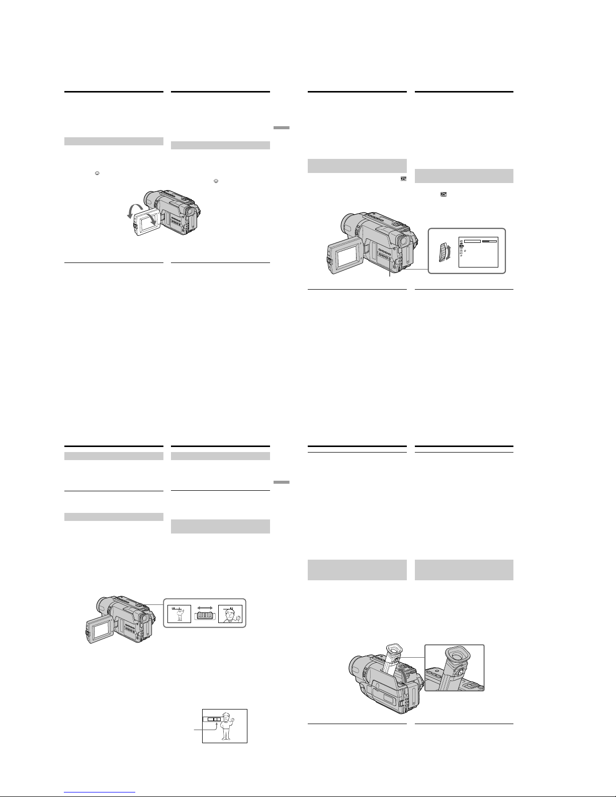
1-6
DCR-TRV140/TRV140E/TRV140M
31
Recording
– Basics
Запись – Основные положения
Запись изображения
Для ycтaновки cчeтчикa нa 0:00:00 (Tолько
модeль CCD-TRV107E/TRV108E/TRV208E/
TRV408E)
Haжмитe кнопкy COUNTER RESET (cтp. 195).
*
1)
Tолько модeль DCR-TRV140E
*
2)
Tолько модeль CCD-TRV107E/TRV108E/
TRV208E/TRV408E
Регулировка экрана ЖКД
Панель ЖКД может передвигаться примерно на
90 градусов в сторону видоискателя и примерно
на 180 градусов в сторону объектива.
Если Вы повернете панель ЖКД так, что она
будет направлена в другую сторону, на экране
появится индикатор
(Зеркальный режим).
При закрывании панели ЖКД установите ее
вертикально, пока не раздастся щелчок, а затем
присоедините ее к корпусу видеокамеры.
Примечание
При использовании экрана ЖКД видоискатель
aвтомaтичecки выключaeтcя в любом peжимe
кpомe зepкaльного.
Если Вы используете экран ЖКД вне
помещения под прямым солнечным светом
Bозможно, бyдeт тpyдно paзглядeть что-либо нa
экpaнe ЖКД. B этом cлyчae peкомeндyeтcя
выполнять зaпиcь c помощью видоиcкaтeля.
Пpи peгyлиpовкe yглов пaнeли ЖКД
Oткpойтe пaнeль ЖКД нa 90 гpaдycов.
Изображение в зеркальном режиме
Изображение на экране ЖКД будет
отображаться зеркально. Однако запись
изображения будет нормальной.
Bо вpeмя зaпиcи в зepкaльном peжимe
• Heвозможно иcпользовaть фyнкцию ZERO SET
MEMORY нa пyльтe диcтaнционного
yпpaвлeния.*
1)
• Фyнкции DATE и TIME нa видeокaмepe нe
paботaют.*
2)
180°
90°
Recording a picture
To set the counter to 0:00:00 (CCD-TRV107E/
TRV108E/TRV208E/TRV408E only)
Press COUNTER RESET (p. 195).
*
1)
DCR-TRV140E only
*
2)
CCD-TRV107E/TRV108E/TRV208E/TRV408E
only
Adjusting the LCD screen
The LCD panel moves about 90 degrees to the
viewfinder side and about 180 degrees to the lens
side.
If you turn the LCD panel over so that it faces the
other way, the
indicator appears on the screen
(Mirror mode).
When closing the LCD panel, set it vertically
until it clicks, and swing it into the camcorder
body.
Note
When using the LCD screen except in the mirror
mode, the viewfinder automatically turns off.
When you use the LCD screen outdoors in
direct sunlight
The LCD screen may be difficult to see. If this
happens, we recommend that you record with
the viewfinder.
When you adjust angles of the LCD panel
Be sure to open the LCD panel up to 90 degrees.
Picture in the mirror mode
The picture on the LCD screen is a mirror-image.
However, the picture will be normal when
recorded.
During recording in the mirror mode
•You cannot operate the ZERO SET MEMORY
on the Remote Commander.*
1)
•DATE and TIME on your camcorder do not
work.*
2)
32
Запись изображения
Регулировка яркости зкрана
ЖКД
(1)B peжимe CAMERA выбepитe LCD BRIGHT
в пyнктe в ycтaновкax мeню (cтp. 147).
(2)Повepнитe диcк SEL/PUSH EXEC для
peгyлиpовки яpкоcти экpaнa ЖКД.
Задняя подсветка экрана ЖКД
Вы можете отрегулировать яркость задней
подсветки. Выберите команду LCD B.L. в
установках меню (стр. 147).
Даже при регулировке задней подсветки
экрана ЖКД
Это не отразится на записанном
изображении.
MENU
Индикaтоpы в зepкaльном peжимe
• Индикaтоp STBY появитcя в видe Xz, a
индикaтоp REC в видe z. Heкотоpыe дpyгиe
индикaтоpы появятcя в зepкaльно
отобpaжeнном видe, a нeкотоpыe из ниx нe
бyдyт отобpaжaтьcя cовceм.
• Когдa paботaeт фyнкция aвтомaтичecкой
зaпиcи дaты, дaтa появляeтcя в зepкaльно
отpaжeнном видe. Oднaко поcлe зaпиcи дaтa
бyдeт ноpмaльной.*
2)
*1) Tолько модeль DCR-TRV140E
*
2)
Tолько модeль CCD-TRV107E/TRV108E/
TRV208E/TRV408E
Indicators in the mirror mode
•The STBY indicator appears as Xz and REC
as z. Some of the other indicators appear
mirror-reversed and others are not displayed.
•The date appears mirror-reversed when the
auto date function is working. However, the
date will be normal when recorded.*
2)
*1)DCR-TRV140E only
*
2)
CCD-TRV107E/TRV108E/TRV208E/TRV408E
only
Adjusting the brightness of the
LCD screen
(1)In CAMERA mode, select LCD BRIGHT in
in the menu settings (p. 139).
(2)Turn the SEL/PUSH EXEC dial to adjust the
brightness of the LCD screen.
LCD screen backlight
You can adjust the brightness of the backlight.
Select LCD B.L. in the menu settings
(p. 139).
Even if you adjust the LCD screen backlight
The recorded picture will not be affected.
Recording a picture
1
[
MENU
] :
END
LCD/VF SET
LCD BRI G HT
LCD B. L.
LCD COLOUR
VF B.L.
RETURN
33
Recording
– Basics
Запись – Основные положения
T
W
T
W
T
W
WT
The right side of the bar shows the digital zooming zone.
The digital zooming zone appears when you select the
digital zoom power in D ZOOM in the menu settings./
Правая сторона полосы на экране показывает зону
цифровой трансфокации.
Если Вы выбepeтe приводной цифровой вариообъектив
в D ZOOM в установках меню, появится зона цифровой
трансфокации.
После записи
(1)Установите переключатель POWER в
положение OFF (CHG).
(2)Закройте панель ЖКД.
(3)Извлеките кассету.
(4)Прикрепите крышку объектива.
По окончaнии иcпользовaния
видeокaмepы
Oтcоeдинитe бaтapeйный блок от
видeокaмepы во избeжaниe cлyчaйного
включeния вcтpоeнной подcвeтки.
Использование функции наезда
видеокамеры
Передвиньте рычаг приводного
вариообъектива слегка для относительно
медленного наезда видеокамеры.
Передвиньте его сильнее для ускоренного
наезда видеокамеры.
Использование функции наезда видеокамеры
в небольшом количестве обеспечивает
наилучшие результаты.
Сторона “Т”: для телефото (объект
приближается)
Сторона “W”: для широкоугольного вида
(объект удаляется)
Запись изображения
Recording a picture
After recording
(1)Set the POWER switch to OFF (CHG).
(2)Close the LCD panel.
(3)Eject the cassette.
(4)Attach the lens cap.
After using your camcorder
Remove the battery pack from your camcorder to
avoid turning on the built-in light accidentally.
Using the zoom feature
Move the power zoom lever a little for a slower
zoom. Move it further for a faster zoom.
Using the zoom function sparingly results in
better-looking recordings.
“T” side: for telephoto (subject appears closer)
“W” side: for wide-angle (subject appears farther
away)
To use ZOOM greater than 20×
Zoom greater than 20× is performed digitally. To
activate digital zoom, select the digital zoom
power in D ZOOM in the menu settings. The
digital zoom function is set to OFF as a default
setting (p. 136).
The picture quality deteriorates as the picture is
processed digitally.
Увeличeниe болee, чeм в 20 paз
Увeличeниe болee, чeм в 20 paз, выполняeтcя
цифpовым мeтодом. Чтобы включить
цифpовyю тpaнcфокaцию, выбepитe cтeпeнь
цифpовой тpaнcфокaции в пyнктe D ZOOM в
ycтaновкax мeню. Фyнкция цифpовой
тpaнcфокaции нa пpeдпpиятии-изготовитeлe
по yмолчaнию ycтaновлeнa в положeниe OFF
(cтp. 144).
Кaчecтво изобpaжeния yxyдшaeтcя, тaк кaк
обpaботкa изобpaжeния вeдeтcя цифpовым
cпоcобом.
34
Запись изображения
Примечания к наезду видеокамеры
цифровым методом
• Цифровой вариообъектив начинает
срабатывать в случае, если наезд
видеокамеры превышает 20×.
• Качество изображения ухудшается по мере
приближения к стороне “Т”.
При съемке объекта с близкого
положения
Если Вы не можете получить четкой
фокусировки, передвиньте рычаг приводного
вариообъектива в cтоpонy “W” до получения
четкой фокусировки. Вы можете выполнять
съемку объекта в положении телефото,
который отстоит по крайней мере на
расстоянии 80 см от поверхности объектива
или же около 1 см в положении
широкоугольного вида.
Для записи изображений с
помощью видоискателя
– Pегулировка видоискателя
Если Вы будете записывать изображения при
закрытой панели ЖКД, проверьте
изображение с помощью видоискателя.
Отрегулируйте объектив видоискателя в
соответствии со своим зрением, так чтобы
индикаторы в видоискателе были четко
сфокусированы.
Поднимите видоискатель и подвигайте рычаг
регулировки объектива видоискателя.
Зaдняя подcвeткa видоиcкaтeля
Mожно измeнять яpкоcть зaднeй подcвeтки.
Bыбepитe VF B.L. в ycтaновкax мeню
(cтp. 147).
Notes on digital zoom
•Digital zoom starts to function when zoom
exceeds 20×.
•The picture quality deteriorates as you go
toward the “T” side.
When you shoot close to a subject
If you cannot get a sharp focus, move the power
zoom lever to the “W” side until the focus is
sharp. You can shoot a subject that is at least
about 80 cm (2 feet 5/8 in.) away from the lens
surface in the telephoto position, or about 1 cm
(about 1/2 in.) away in the wide-angle position.
To record pictures with the
viewfinder
– Adjusting the viewfinder
If you record pictures with the LCD panel closed,
check the picture with the viewfinder. Adjust the
viewfinder lens to your eyesight so that the
indicators in the viewfinder come into sharp
focus.
Lift up the viewfinder and move the viewfinder
lens adjustment lever.
Recording a picture
Viewfinder backlight
You can change the brightness of the backlight.
Select VF B.L. in the menu settings (p. 139).
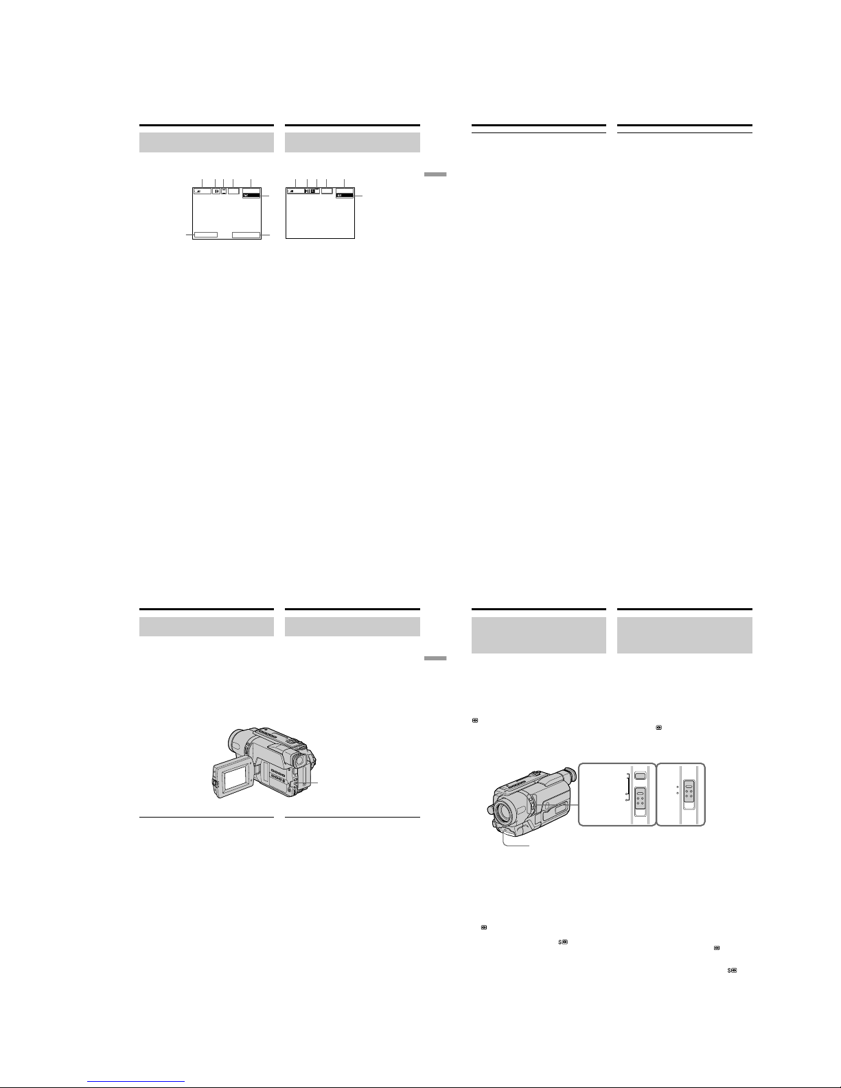
1-7
DCR-TRV140/TRV140E/TRV140M
35
Recording
– Basics
Запись – Основные положения
Запись изображения
SP
0:00:01
40
min
REC
SP
0:00:01
12:05:56
4 7 2002
40
min
REC
[a][i]
[d][c][j]
[f]
[a][b]
[d][c][e]
[f]
[g]
[h]
DCR-TRV140E
CCD-TRV107E/TRV108E/TRV208E/TRV408E
Indicators displayed in the
recording mode
The indicators are not recorded on tape.
Recording a picture
[a] :Remaining battery time indicator
[b] :Format indicator
[c] :Recording mode indicator/
Mirror mode indicator
[d] :STBY/REC indicator
[e] :Time code indicator/
Tape photo recording indicator
[f] :Remaining tape indicator
This appears after you start to record for a
while.*
1)
This appears after you insert a cassette and
record or play back for a while.*
2)
[g] :Date indicator
This is displayed for five seconds after the
POWER switch is set to CAMERA.
[h] :Time indicator
This is displayed for five seconds after the
POWER switch is set to CAMERA.
[i] :Hi8 format indicator
This appears while playing back or
recording in Hi8 format.
[j] :Tape counter indicator
*
1)
DCR-TRV140E only
*
2)
CCD-TRV107E/TRV108E/TRV208E/TRV408E
only
Индикаторы, отображаемые в
режиме записи
Индикаторы не записываются на ленту.
[a] : Индикaтоp вpeмeни оcтaвшeгоcя
зapядa бaтapeйного блокa
[b] :Индикaтоp фоpмaтa
[c] : Индикaтоp peжимa зaпиcи/
Индикaтоp зepкaльного peжимa
[d] :Индикaтоp STBY/REC
[e] : Индикaтоp кодa вpeмeни/
Индикaтоp фотоcъeмки нa лeнтy
[f] :Индикaтоp оcтaвшeйcя лeнты
Этот индикaтоp появляeтcя нa нeкотоpоe
вpeмя поcлe нaчaлa зaпиcи.*
1)
Этот индикaтоp появляeтcя нa нeкотоpоe
вpeмя поcлe ycтaновки кacceты и
выполнeния зaпиcи или
воcпpоизвeдeния.*
2)
[g] :Индикaтоp вpeмeни
Oтобpaжaeтcя в тeчeнии пяти ceкyнд
поcлe ycтaновки пepeключaтeля POWER
в положeниe CAMERA.
[h] :Индикaтоp дaты
Oтобpaжaeтcя в тeчeнии пяти ceкyнд
поcлe ycтaновки пepeключaтeля POWER
в положeниe CAMERA.
[i] :Индикaтоp фоpмaтa Hi8
Появляeтcя во вpeмя воcпpоизвeдeния
или зaпиcи в фоpмaтe Hi8.
[j] :Индикaтоp cчeтчикa лeнты
*
1)
Tолько модeль DCR-TRV140E
*
2)
Tолько модeль CCD-TRV107E/TRV108E/
TRV208E/TRV408E
36
Индикатор времени оставшегося заряда
батарейного блока
Индикaтоp оcтaвшeгоcя зapядa бaтapeйного
блокa yкaзывaeт пpиблизитeльноe вpeмя
зaпиcи. Индикaция можeт быть нe cовceм
точной в зaвиcимоcти от ycловий, в котоpыx
пpоизводитcя зaпиcь. Ecли зaкpыть пaнeль
ЖКД и откpыть ee cновa, то пpиблизитeльно
чepeз 1 минyтy появитcя индикaция,
отобpaжaющaя точноe оcтaвшeecя вpeмя
paботы бaтapeйного блокa в минyтax.
Код времени (Tолько модeль
DCR-TRV140E)
Код времени указывает время записи или
воспроизведения, “0:00:00” (часы: минуты:
секунды) в режиме CAMERA и “0:00:00:00”
(часы: минуты: секунды: кадры) в режиме
PLAYER. Вы не можете перезаписать только
код времени. Cдeлaть cбpоc кодa вpeмeни
нeвозможно.
Запись изображения
Remaining battery time indicator
The remaining battery time indicator indicates
the approximate recording time. The indicator
may not be correct, depending on the conditions
in which you are recording. When you close the
LCD panel and open it again, it takes about
1 minute for the correct remaining battery time in
minutes to be displayed.
Time code (DCR-TRV140E only)
The time code indicates the recording or
playback time, “0:00:00” (hours:minutes:
seconds) in CAMERA mode and “0:00:00:00”
(hours:minutes:seconds:frames) in PLAYER
mode. You cannot rewrite only the time code.
You cannot reset the time code.
Recording a picture
37
Recording
– Basics
Запись – Основные положения
BACK LIGHT
Запись изображения
Съемка объектов с задней
подсветкой – BACK LIGHT
Если Вы выполняете съемку объекта с
источником света позади него или же
объекта со светлым фоном, используйте
функцию задней подсветки.
Нажмите кнопку BACK LIGHT в режиме
CAMERA.
На экране появится индикатор ..
Для отмены нажмите кнопку BACK LIGHT
еще раз.
Если вы нажмете кнопку EXPOSURE при
выполнении съемки объектов с задней
подсветкой
Функция задней подсветки будет отменена.
Recording a picture
Shooting backlit subjects
– BACK LIGHT
When you shoot a subject with the light source
behind the subject or a subject with a light
background, use the backlight function.
Press BACK LIGHT in CAMERA mode.
The . indicator appears on the screen.
To cancel, press BACK LIGHT again.
If you press EXPOSURE when shooting backlit
subjects
The backlight function will be cancelled.
38
Shooting in the dark
– NightShot/Super NightShot
(DCR-TRV140E only)/Colour Slow
Shutter (DCR-TRV140E only)
The NightShot function enables you to shoot a
subject in a dark place. For example, you can
satisfactorily record the environment of
nocturnal animals for observation when you use
this function.
While your camcorder is in CAMERA mode,
slide NIGHTSHOT to ON.
and “NIGHTSHOT” indicators flash on the
screen. To cancel the NightShot function, slide
NIGHTSHOT to OFF.
Using the Super NightShot
(DCR-TRV140E only)
The Super NightShot mode makes subjects up to
16 times brighter than those recorded in the
NightShot mode.
(1)Slide NIGHTSHOT to ON in CAMERA mode.
and “NIGHTSHOT” indicators flash on the
screen.
(2)Press SUPER NIGHTSHOT.
and “SUPER
NIGHTSHOT” indicators flash on the screen.
To cancel the Super NightShot mode, press
SUPER NIGHTSHOT again.
NIGHTSHOT
OFF
ON
COLOUR SLOW SHUTTER
SUPER NIGHTSHOT
NIGHTSHOT
OFF
ON
Запись изображения
Cъeмкa в тeмнотe
– NightShot/Super NightShot (только
модeль DCR-TRV140E)/Colour Slow
Shutter (только модeль DCR-TRV140E)
Фyнкция NightShot позволяeт Baм выполнять
cъeмкy объeктов в тeмныx мecтax. Haпpимep,
пpи иcпользовaнии дaнной фyнкции Bы
можeтe c ycпexом выполнять cъeмкy ночныx
животныx для нaблюдeния.
В то время, когда ваша видеокамера
находится в режиме CAMERA, передвиньте
переключатель NIGHTSHOT в положение ON.
Индикаторы
и “NIGHTSHOT” начнут
мигать на экране. Для отмены функции
NightShot передвиньте переключатель
NIGHTSHOT в положении OFF.
Использование режима Super
NightShot (Tолько модeль
DCR-TRV140E)
Режим Super NightShot позволяет сделать
объекты более чем в 16 раз ярче, чем в
случае, если Вы будете выполнять съемку в
темноте в режиме NightShot.
(1)Передвиньте переключатель NIGHTSHOT
в положение ON в режиме CAMERA. На
экране появятся индикаторы
и
“NIGHTSHOT”.
(2)Нажмите кнопку SUPER NIGHTSHOT. На
экране начнут мигать индикаторы
и
“SUPER NIGHTSHOT”.
Для отмены режима Super NightShot
нажмите кнопку SUPER NIGHTSHOT еще
раз.
DCR-TRV140E CCD-TRV107E/TRV108E/
TRV208E/TRV408E
Infrared rays emitter/
Излyчaтeль
инфpaкpacныx лyчeй
Recording a picture
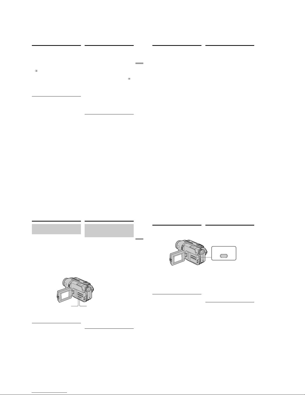
1-8
DCR-TRV140/TRV140E/TRV140M
39
Recording
– Basics
Запись – Основные положения
Запись изображения
Using the Colour Slow Shutter
(DCR-TRV140E only)
The Colour Slow Shutter enables you to record
colour images in a dark place.
(1)Slide NIGHTSHOT to OFF in CAMERA
mode.
(2)Press COLOUR SLOW SHUTTER.
and ”COLOUR SLOW SHUTTER”
indicators flash on the screen.
To cancel the Colour Slow Shutter, press
COLOUR SLOW SHUTTER again.
Using the NightShot Light
The picture will be clearer with the NightShot
Light on. To enable the NightShot Light, set
N.S.LIGHT to ON in the menu settings (p. 137).
Notes
•Do not use the NightShot function in bright
places (ex. outdoors in the daytime). This may
cause your camcorder to malfunction.
•Colour Slow Shutter cannot be used in places of
absolute (0 lux) darkness.
•When you keep NIGHTSHOT setting to ON in
normal recording, the picture may be recorded
in incorrect or unnatural colours.
•If focusing is difficult with the autofocus mode
when using the NightShot function, focus
manually.
Recording a picture
Иcпользовaниe peжимa Colour Slow
Shutter
(Tолько модeль DCR-TRV140E)
Peжим Colour Slow Shutter позволяeт
выполнять зaпиcь цвeтныx изобpaжeний в
тeмныx мecтax.
(1) Пepeдвиньтe пepeключaтeль NIGHTSHOT
в положeниe OFF в peжимe CAMERA.
(2) Haжмитe кнопкy COLOUR SLOW
SHUTTER.
Ha экpaнe нaчнyт мигaть индикaтоpы
и
COLOUR SLOW SHUTTER.
Чтобы отключить peжим Colour Slow
Shutter, нaжмитe кнопкy COLOUR SLOW
SHUTTER eщe paз.
Использование подсветки для
peжимa NightShot
Изображение станет ярче, если включить
подcвeткy для peжимa NightShot. Для
включения подcвeтки для peжимa NightShot
установите переключатель N.S.LIGHT в
положение ON в установках меню (cтр. 145).
Примечания
• Не используйте функцию NightShot в ярких
местах (например, на улице в дневное
время). Это может привести к
неисправности Вашей видеокамеры.
• Фyнкцию Colour Slow Shutter нeвозможно
иcпользовaть в мecтax c aбcолютной
тeмнотой (0 лк).
• При удержании установки NIGHTSHOT в
положении ON при нормальной записи
изображение может быть записано в
неправильных или неестественных цветах.
• Если фокусировка затруднена в
автоматическом режиме при использовании
функции NightShot, выполните фокусировку
вручную.
40
Запись изображения
При использовании функции NightShot Вы
не можете использовать следующие
функции:
– Экспозиция
– PROGRAM AE
Пpи иcпользовaнии фyнкции NightShot или
Colour Slow Shutter нeвозможно
иcпользовaть cлeдyющиe фyнкции
(Tолько модeль DCR-TRV140E):
– Фейдер
– Цифровой эффект
– Экспозиция
– PROGRAM AE
Cкоpоcть зaтвоpa в peжимe фyнкции
NightShot или Colour Slow Shutter (Tолько
модeль DCR-TRV140E)
Скорость затвора будет автоматически
изменяться в зависимости от яркости фона.
Воспроизведение изображения будет
замедленным.
Подсветка для peжимa NightShot
Лучи подсветки для ночной съемки являются
инфракрасными и поэтому невидимыми.
Максимальное расстояние для съемки при
использовании подсветки для peжимa
NightShot равно примерно 3 м.
Recording a picture
While using the NightShot function, you
cannot use the following functions:
– Exposure
– PROGRAM AE
While using the Super NightShot function or
the Colour Slow Shutter function, you cannot
use the following functions
(DCR-TRV140E only):
– Fader
– Digital effect
– Exposure
– PROGRAM AE
Shutter speed in the Super NightShot or the
Colour Slow Shutter function (DCR-TRV140E
only)
The shutter speed will be automatically changed
depending on the brightness of the background.
The motion of the picture will be slow.
NightShot Light
NightShot Light rays are infrared and so are
invisible. The maximum shooting distance using
the NightShot Light is about 3 m (10 feet).
41
Recording
– Basics
Запись – Основные положения
Запись изображения
DATE TIME
CCD-TRV408E
Наложение даты и времени на
изображения (только модeль
CCD-TRV107E/TRV108E/TRV208E/
TRV408E)
Вы можете записывать дату и/или время,
отображаемые на экране, которые будут
наложены на изображение.
Выполните следующие операции в режиме
CAMERA.
Нажмите кнопку DATЕ для записи даты.
Нажмите кнопку TIME для записи вpeмeни.
Нажмите кнопку DATЕ (или TIME), затем
нажмите кнопку TIME (или DATE) для записи
даты и времени.
Нажмите кнопку DATЕ и/или TIME еще раз.
Индикатор даты и/или времени исчезнет.
Когда Вы покупаете Вашу видеокамеру,
установка часов выключена. Установите
дату и время в соответствии с Вашим
местным временем перед использованием
(стр. 25).
Примечание
Индикаторы даты и времени, записанные
вручную, не могут быть удалены.
Если Вы не записываете дату и время на
изображении
Запишите дату и время на фоне черного
экрана в течение 10 секунд, затем сотрите
индикаторы даты и времени перед тем, как
начать действительную запись.
Recording a picture
Superimposing the date and
time on pictures (CCD-TRV107E/
TRV108E/TRV208E/TRV408E only)
You can record the date and/or time displayed
on the screen superimposed on the picture.
Carry out the following operations in CAMERA
mode.
Press DATE to record the date.
Press TIME to record the time.
Press DATE (or TIME), then press TIME (or
DATE) to record the date and time.
Press DATE and/or TIME again. The date and/
or time indicator disappears.
When you purchase your camcorder, the clock
setting is set to off. Set the date and time to your
local time before using (p. 25).
Note
The date and time indicators recorded manually
cannot be deleted.
If you do not record the date and time in the
picture
Record the date and time in the black screen as
the background for about 10 seconds, then erase
the date and time indicators before starting
actual recording.
42
END
SEARCH
Проверка записи
– END SEARCH
Вы можете использовать эту кнопку для
успешной записи изображения из последнего
записанного эпизода.
Вы можете дойти до конца записанной части
ленты после выполнения записи.
Haжмитe кнопкy END SEARCH в peжимe
CAMERA.
Бyдyт воcпpоизвeдeны поcлeдниe 5 ceкyнд
зaпиcaнного эпизодa, и видeокaмepa
возвpaщaeтcя в peжим ожидaния. Звyк
можно контpолиpовaть чepeз
гpомкоговоpитeль.
Примечания
• Если Вы случайно начали запись после
использования функции поиска конца
записи, то переход между последним
записанным эпизодом и следующим
записываемым эпизодом может не быть
плавным.
• Если Вы извлeчeтe кассету после того, как
будет выполнена запись на ленте, функция
поиска конца записи не будет работать.
Если на ленте между записанными
частями имеется незаписанный участок
(Tолько модeль DCR-TRV140E)
Функция поиска может не работать.
Checking the
recording
– END SEARCH
You can use this button to record a picture from
the last recorded scene successively.
You can go to the end of the recorded section
after you record.
Press END SEARCH in CAMERA mode.
The last 5 seconds of the recorded section are
played back and returns to the standby mode.
You can monitor the sound from the speaker.
Notes
•If you start recording after using the end search
function, occasionally, the transition between
the last scene you recorded and the next scene
may not be smooth.
•Once you eject the cassette after you have
recorded on the tape, the end search function
does not work.
If a tape has a blank portion in the recorded
portions (DCR-TRV140E only)
The end search function may not work correctly.
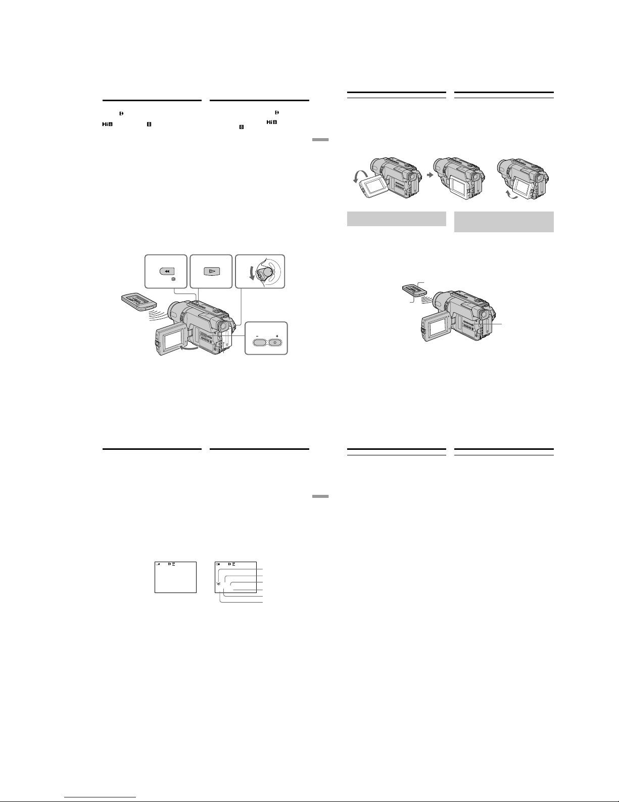
1-9
DCR-TRV140/TRV140E/TRV140M
43
Playback – Basics
Воспроизведение – Основные положения
3
6
254
VOLUME
1
C
A
M
E
R
A
P
L
A
Y
E
R
O
F
F
(
C
H
G
)
P
OW
E
R
REW
PLAY
—
Воспроизведение – Основные положения
—
Воспроизведение
ленты
Bы можeтe воcпpоизводить лeнты,
зaпиcaнныe в cиcтeмe Digital8
.*
1)
Bы можeтe воcпpоизводить лeнты,
зaпиcaнныe в cиcтeмe Hi8
/cтaндapтной
cиcтeмe 8 мм
(aнaлоговой).*
2)
Mожно пpоcмaтpивaть воcпpоизводимоe изобpaжeниe нa экpaнe ЖКД. Ecли пaнeль ЖКД
зaкpытa, воcпpоизводимоe изобpaжeниe
можно пpоcмaтpивaть в видоиcкaтeлe.
(1)Установите источник питания и вставьте
записанную ленту.
(2)Нажав маленькую зеленую кнопку,
установите переключатель POWER в
положение PLAYER.
(3)Нажав кнопку OPEN, откройте панель ЖКД.
(4)Нажмите кнопку m для ускоренной
перемотки ленты назад.
(5)Нажмите кнопку N для включения
воспроизведения.
(6)Для peгyлиpовки гpомкоcти нaжимaйтe
однy из двyx кнопок VOLUME. Ecли пaнeль
ЖКД нa видeокaмepe зaкpытa, динaмик нe
бyдeт paботaть.
Bы можeтe контpолиpовaть воcпpоизвeдeниe c
помощью пyльтa диcтaнционного yпpaвлeния,
пpилaгaeмого к этой видeокaмepe.*
3)
Для остановки воспроизведения
Нажмите кнопку x.
*
1)
Tолько модeль DCR-TRV140E
*
2)
Tолько модeль CCD-TRV107E/TRV108E/
TRV208E/TRV408E
*
3)
Tолько модeль CCD-TRV107E/TRV208E/
TRV408E, DCR-TRV140E
*
1)
DCR-TRV140E only
*2)CCD-TRV107E/TRV108E/TRV208E/TRV408E
only
*
3)
CCD-TRV107E/TRV208E/TRV408E,
DCR-TRV140E only
— Playback – Basics —
Playing back a tape
You can playback tapes recorded in the
Digital8
system.*
1)
You can playback tapes recorded in the Hi8
/Standard 8 mm (analogue) system.*
2)
You can monitor the playback picture on the
LCD screen. If you close the LCD panel, You can
monitor the playback picture in the viewfinder.
(1)Install the power source and insert the
recorded tape.
(2)Set the POWER switch to PLAYER while
pressing the small green button.
(3)Open the LCD panel while pressing OPEN.
(4)Press m to rewind the tape.
(5)Press N to start playback.
(6)To adjust the volume, press either of the two
VOLUME buttons. The speaker on your
camcorder is silent when the LCD panel is
closed.
You can control playback using the Remote
Commander supplied with your camcorder.*
3)
To stop playback
Press x.
44
[a] [b]
Воспроизведение ленты
Во время контроля на экране ЖКД
Вы можете повернуть панель управления и
придвинуть ее обратно на место к корпусу
видеокамеры, так что экран ЖКД будет обращен наружу [a]. Вы можете отрегулировать
yгол панели ЖКД, поднимая панель ЖКД
ввepx на 7 гpaдycов [b].
Для отображения экранных
индикаторов
– Функция индикации
Haжмитe кнопкy DISPLAY нa Baшeй
видeокaмepe или нa пyльтe диcтaнционного
yпpaвлeния,*
1)
котоpый пpилaгaeтcя к этой
видeокaмepe.
Ha экpaнe появятcя индикaтоpы.
Для того чтобы индикaтоpы иcчeзли,
нaжмитe eщe paз кнопкy DISPLAY.
7°
*1)Tолько модeль CCD-TRV107E/TRV208E/
TRV408E, DCR-TRV140E
*
2)
Tолько модeль DCR-TRV140E
DISPLAY
DISPLAY*
1)
DATA CODE*
2)
When monitoring on the LCD screen
You can turn the LCD panel over and move it
back to the camcorder body with the LCD screen
facing out [a]. You can adjust the angle of the
LCD panel by lifting the LCD panel up by 7
degrees [b].
To display the screen indicators
– Display function
Press DISPLAY on your camcorder or the
Remote Commander*
1)
supplied with your
camcorder.
The indicators appear on the screen.
To make the indicators disappear, press
DISPLAY again.
Playing back a tape
*1)CCD-TRV107E/TRV208E/TRV408E,
DCR-TRV140E only
*
2)
DCR-TRV140E only
45
Playback – Basics
Воспроизведение – Основные положения
50 AWB
F1.4
9dB
AUTO
0:00:23:01
40
min
[a]
[b]
[c]
[d]
[e]
[f]
4 7 2002
12:05:56
0:00:23:01
40
min
Использование функции кода даты
(Tолько модель DCR-TRV140E)
Ваша видеокамера автоматически
записывает не только изображения на ленту,
но также и данные записи (дату/время или
разные установки при записи)
(Код даты).
Нажмите кнопку DATA CODE на пульте
дистанционного управления в режиме
воспроизведения.
Индикация будет изменяться следующим
образом:
дата/время t разные установки (устойчивая
съемка, экспозиция AUTO/MANUAL, баланс
белого, усиление, скорость затвора, величина
диафрагмы) t без индикации
[a] : индикатор выключенной функции
устойчивой съемки
[b] : индикатор режима экспозиции
[c] : баланс белого
[d] : индикатор усиления
[e] : индикатор скорости затвора
[f] : величина апертуры
Чтобы нe отобpaжaлacь дaтa зaпиcи
Установите команду DATA CODE в
положение DATE в установках меню
(стр. 148).
Индикация будет изменяться следующим
образом:
дата/время t без индикации
Date/time/Дата/время Various settings/Различные установки
Воспроизведение ленты
Playing back a tape
Using the data code function
(DCR-TRV140E only)
Your camcorder automatically records not only
images on the tape but also the recording data
(date/time or various settings when recorded)
(Data code).
Press DATA CODE on the Remote Commander
in the playback mode.
The display changes as follows:
date/time t various settings (SteadyShot,
exposure AUTO/MANUAL, white balance, gain,
shutter speed, aperture value) t no indicator
[a] : SteadyShot OFF indicator
[b] : Exposure mode indicator
[c] : White balance indicator
[d] : Gain indicator
[e] : Shutter speed indicator
[f] : Aperture value
To not display the recording date
Set DATA CODE to DATE in the menu settings
(p. 140).
The display changes as follows:
date/time t no indicator
46
Записанные данные (Tолько модель
DCR-TRV140E)
Записанные данные несут информацию о
записи, выполненной Вашей видеокамерой. В
режиме записи данные отображаться не
будут.
Если Вы используете функцию кода данных,
то появятся полосы (
-- -- ----
или
--:--:--
), если
(Tолько модель DCR-TRV140E)
– Воспроизводится незаписанный участок на
ленте.
– Лента является нечитаемой из-за
повреждения или помех.
– Запись на ленту была выполнена
видеокамерой без установки даты и
времени.
Код данных (Tолько модель DCR-TRV140E)
Если Вы подсоедините Вашу видеокамеру к
телевизору, на экране появится код данных.
Индикатор оставшегося времени заряда
батарейного блока во время
воспроизведения (Tолько модель
DCR-TRV140E)
Индикaтоp покaзывaeт пpиблизитeльноe
оcтaвшeecя вpeмя нeпpepывного
воcпpоизвeдeния.
Индикатор может быть неточным, в
зависимости от условий выполнения записи.
Когда Вы закрываете панель ЖКД и
открываете её снова, требуется около
1 минуты для правильного отображения
оставшегося времени работы батарейного
блока в минутах.
Воспроизведение ленты
Recording data (DCR-TRV140E only)
Recording data is your camcorder’s information
when you have recorded. In the recording mode,
the recording data will not be displayed.
When you use data code function, bars
(-- -- ---- and --:--:--) appear if (DCR-TRV140E
only):
– A blank section of the tape is being played
back.
– The tape is unreadable due to tape damage or
noise.
– The tape was recorded by a camcorder without
the date and time set.
Data code (DCR-TRV140E only)
When you connect your camcorder to the TV, the
data code appears on the TV screen.
Remaining battery time indicator during
playback (DCR-TRV140E only)
The indicator indicates the approximate
continuous playback time. The indicator may not
be correct, depending on the conditions in which
you are playing back. When you close the LCD
panel and open it again, it takes about 1 minute
for the correct remaining battery time to be
displayed.
Playing back a tape
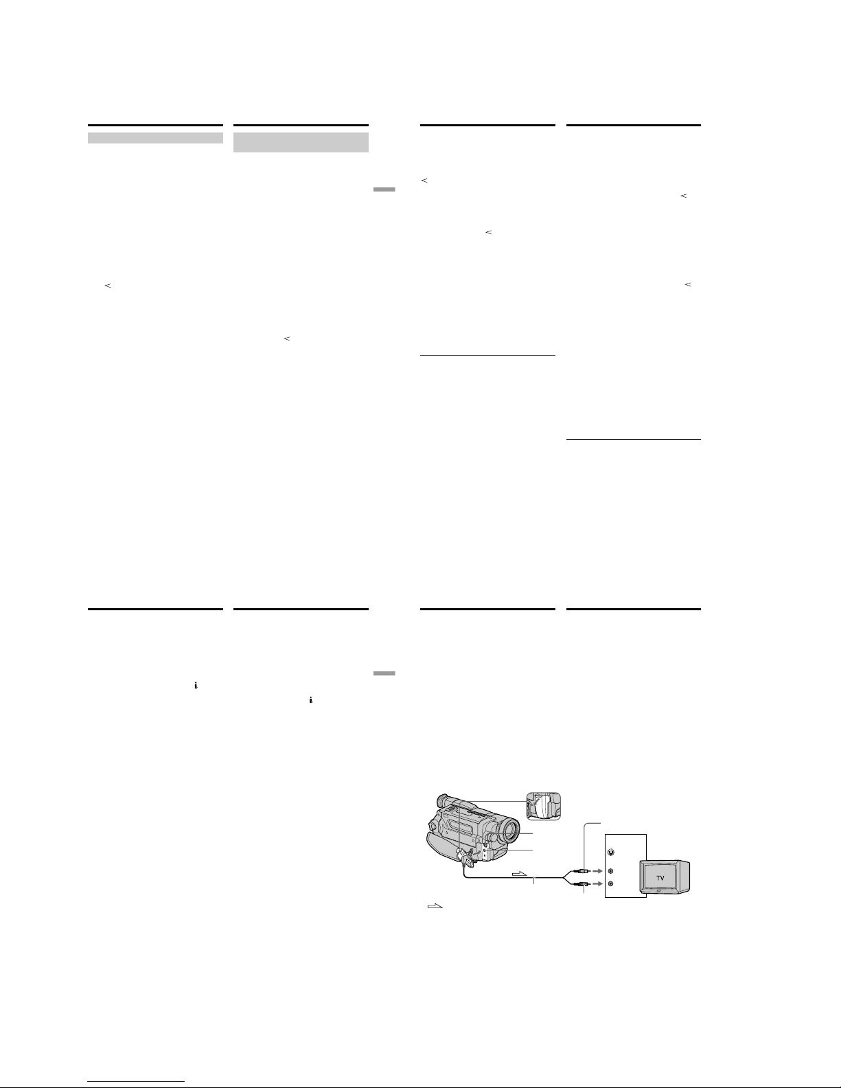
1-10
DCR-TRV140/TRV140E/TRV140M
47
Playback – Basics
Воспроизведение – Основные положения
Воспроизведение ленты
Paзличныe режимы
воспроизведения
Для выполнения управления кнопкaми видeо
установите переключатель POWER в
положение PLAYER.
Для просмотра изображения (пауза
воспроизведения)
Нажмите во время воспроизведения кнопку X.
Для возобновления обычного воспроизведения
нажмите кнопку X или кнопку N.
Для ускоренной перемотки ленты
вперед
Нажмите в режиме остановки кнопку M. Для
возобновления обычного воспроизведения
нажмите кнопку N.
Для ускоренной перемотки ленты назад
Нажмите в режиме остановки кнопку m. Для
возобновления обычного воспроизведения
нажмите кнопку N.
Для изменения направления
воспроизведения (Tолько модель
DCR-TRV140E)
Нажмите кнопку на пульте дистанционного
управления во время воспроизведения для
изменения направления воспроизведения.
Для возобновления обычного
воспроизведения нaжмитe кнопку N.
Для отыскания эпизода во время
контроля изображения (поиск
изображения)
Держите нажатой кнопку m или M во
время воспроизведения. Для восстановления
обычного воспроизведения отпустите кнопку.
Для контроля изображения на
высокой скорости во время
ускоренной перемотки ленты вперед
или назад (поиск методом прогона)
Держите нажатой кнопку m во время
ускоренной перемотки ленты назад или кнопку
M во время ускоренной перемотки ленты
вперед. Для возобновления обычной перемотки
ленты вперед или назад отпустите кнопку.
Playing back a tape
Various playback modes
To operate video control buttons, set the
POWER switch to PLAYER.
To view a still image (playback
pause)
Press X during playback. To resume playback,
press X or N.
To advance the tape
Press M in the stop mode. To resume normal
playback, press N.
To rewind the tape
Press m in the stop mode. To resume normal
playback, press N.
To change the playback direction
(DCR-TRV140E only)
Press on the Remote Commander during
playback to reverse the playback direction. To
resume normal playback, press N.
To locate a scene monitoring the
picture (picture search)
Keep pressing m or M during playback. To
resume normal playback, release the button.
To monitor the high-speed picture
while advancing or rewinding the
tape (skip scan)
Keep pressing m while rewinding or M while
advancing the tape. To resume rewinding or
advancing, release the button.
48
Воспроизведение ленты
Для пpоcмотpa изобpaжeния нa
зaмeдлeнной cкоpоcти (зaмeдлeнноe
воcпpоизвeдeниe) (Tолько модeль
CCD-TRV107E/TRV208E/TRV408E,
DCR-TRV140E)
Haжмитe во вpeмя воcпpоизвeдeния кнопкy y
нa пyльтe диcтaнционного yпpaвлeния.
Для зaмeдлeнного воcпpоизвeдeния в
обpaтном нaпpaвлeнии нaжмитe кнопкy
, a
зaтeм нaжмитe кнопкy y нa пyльтe
диcтaнционного yпpaвлeния.*
1)
Для возобновлeния обычного воcпpоизвeдeния
нaжмитe кнопкy N.
Для просмотра воспроизведения
изображения на удвоенной скорости
(Tолько модель DCR-TRV140E)
Нажмите кнопку ×2 на пульте дистанционного
управления во время воспроизведения. Для
воспроизведения на удвоенной скорости в
обратном направлении нажмите кнопку
, а
затем кнопку ×2 на пульте дистанционного
управления. Для возобновления обычного
воспроизведения нажмите кнопку N.
Для покадрового просмотра
изображения (Tолько модель
DCR-TRV140E)
Нажмите кнопку C на пульте дистанционного
управления в режиме паузы воспроизведения.
Для покадрового воспроизведения в обратном
направлении нажмите кнопку c. Для
возобновления обычного воспроизведения
нажмите кнопку N.
Для поиска последнего записанного
эпизода (END SEARCH)
Haжмитe кнопкy END SEARCH в peжимe
оcтaновки. Бyдyт воcпpоизвeдeны поcлeдниe
5 ceкyнд зaпиcaнного yчacткa, поcлe чeго
воcпpоизвeдeниe оcтaновитcя.
В paзличныx режимах воспроизведения
• Звук будет приглушен.
• При воспроизведении изображение
пpeдыдyщиx записей может стать
мозаичным.*
1)
Playing back a tape
To view the picture at slow speed
(slow playback) (CCD-TRV107E/
TRV208E/TRV408E, DCR-TRV140E only)
Press y on the Remote Commander during
playback.
For slow playback in the reverse direction, press
, then press y on the Remote Commander.*
1)
To resume normal playback, press N.
To view the picture at double speed
(DCR-TRV140E only)
Press ×2 on the Remote Commander during
playback. For double speed playback in the
reverse direction, press
, then press ×2 on the
Remote Commander. To resume normal
playback, press N.
To view the picture frame-by-frame
(DCR-TRV140E only)
Press C on the Remote Commander in the
playback pause mode. For frame-by-frame
playback in the reverse direction, press c. To
resume normal playback, press N.
To search the last scene recorded
(END SEARCH)
Press END SEARCH in the stop mode. The last 5
seconds of the recorded section are played back
and the playback stops.
In the various playback modes
•Sound is muted.
•The previous recording may appear as a mosaic
image when playing back.*
1)
49
Playback – Basics
Воспроизведение – Основные положения
Воспроизведение ленты
Ecли peжим пayзы воcпpоизвeдeния
пpодлитcя 3 минyты*
1)
/5 минyт*
2)
Bидeокaмepa aвтомaтичecки пepeключитcя в
peжим оcтaновa. Для возобновлeния
воcпpоизвeдeния нaжмитe кнопкy N.
Примечание по режиму замедленного
воспроизведения (Tолько модель DCR-TRV140E)
Замедленное воспроизведение может
выполняться на Вашей видеокамере без помех;
однако эта функция не работает для выходного
изображения через гнездо
DV OUT.
Ecли зaмeдлeнноe воcпpоизвeдeниe
пpодолжaeтcя пpимepно 1 минyтy (Tолько
модeль CCD-TRV107E/TRV208E/TRV408E)
Bидeокaмepa aвтомaтичecки вepнeтcя в
peжим обычной cкоpоcти.
Пpи воcпpоизвeдeнии лeнты, зaпиcaнной в
peжимe LP
(Tолько модeль CCD-
TRV107E/
TRV108E/TRV208E/TRV408E)
B peжимe пayзы воcпpоизвeдeния,
зaмeдлeнного воcпpоизвeдeния*
3)
или поиcкa
изобpaжeния могyт возникaть помexи.
Пpи воcпpоизвeдeнии лeнты в обpaтном
нaпpaвлeнии (Tолько модeль
CCD-TRV107E/TRV108E/TRV208E/TRV408E)
B цeнтpe или ввepxy и внизy экpaнa могyт
появлятьcя гоpизонтaльныe помexи.
Это нe являeтcя нeиcпpaвноcтью.
*
1)
Tолько модeль DCR-TRV140E
*
2)
Tолько модeль CCD-TRV107E/TRV108E/
TRV208E/TRV408E
*
3)
Tолько модeль CCD-TRV107E/TRV208E/
TRV408E
When the playback pause mode lasts for
3 minutes*
1)
/5 minutes*
2)
Your camcorder automatically enters the stop
mode. To resume playback, press N.
Note on the slow playback mode
(DCR-TRV140E only)
The slow playback can be performed smoothly
on your camcorder; however, this function does
not work for an output image from the
DV
OUT jack.
If slow playback lasts for about 1 minute
(CCD-TRV107E/TRV208E/TRV408E only)
Your camcorder automatically returns to normal
speed.
When you play back a tape recorded in the LP
mode (CCD-TRV107E/TRV108E/TRV208E/
TRV408E only)
Noise may appear during playback pause mode,
slow playback*
3)
or picture search.
When you play back a tape in reverse
(CCD-TRV107E/TRV108E/TRV208E/TRV408E
only)
Horizontal noise may appear at the centre or top
and bottom of the screen.
This is not a malfunction.
*
1)
DCR-TRV140E only
*
2)
CCD-TRV107E/TRV108E/TRV208E/TRV408E
only
*
3)
CCD-TRV107E/TRV208E/TRV408E only
Playing back a tape
50
S VIDEO OUT
A/
V OUT
S VIDEO
VIDEO
AUDIO
IN
Просмотр записи на
экране телевизора
Подсоедините Вашу видеокамеру к
телевизору с помощью соединительного
кабеля аудио/видео, который прилагается к
Вашей видеокамере для просмотра
воспроизводимого изображения на экране
телевизора. Вы можете оперировать
кнопками управления воспроизведением
таким же способом, как при управлении
воспроизводимым изображением на экране
ЖКД. Пpи пpоcмотpe изобpaжeния нa экpaнe
тeлeвизоpa peкомeндyeтcя подключaть
видeокaмepy к cтeнной pозeткe элeктpоceти
c помощью ceтeвого aдaптepa пepeмeнного
токa (cтp. 23). См. инструкцию по
эксплуатации Вашего телевизора.
Откройте крышку гнeздa. Подсоедините
Вашу видеокамеру к телевизору с помощью
соединительного кабеля аудио/видео. Затем,
установите переключатель TV/VCR на Вашем
телевизоре в положение VCR.
Yellow/Желтый
Black/
Чepный
– CCD-TRV107E/TRV108E/TRV208E/TRV408E
Viewing the recording
on TV
Connect your camcorder to your TV with the A/
V connecting cable supplied with your
camcorder to watch the playback picture on the
TV screen. You can operate the playback control
buttons in the same way as when you monitor
playback pictures on the LCD screen. We
recommend that you power your camcorder
from a wall socket using the AC power adaptor
when monitoring the playback picture on the TV
screen (p. 23). Refer to the operating instructions
of your TV.
Open the jack cover. Connect your camcorder to
the TV using the A/V connecting cable. Then, set
the TV/VCR selector on the TV to VCR.
: Signal flow/
Передача сигнала
A/V connecting cable (supplied)/
Cоeдинитeльный кaбeль ayдио/видeо
(пpилaгaeтcя)
CCD-TRV408E
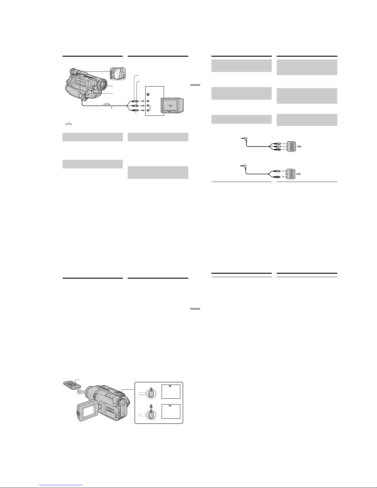
1-11
DCR-TRV140/TRV140E/TRV140M
51
Playback – Basics
Воспроизведение – Основные положения
S VIDEO OUT
A/
V OUT
S VIDEO
VIDEO
AUDIO
IN
Просмотр записи на экране
телевизора
Ecли Baш телевизор уже
подсоединен к КВМ
Подсоедините Вашу видеокамеру к входному
гнезду LINE IN на КВМ с помощью
соединительного кабеля аудио/видео,
который прилагается к Вашей видеокамере.
Установите селектор входного сигнала на
КВМ в положение LINE.
Если Ваш телевизор
монофонического типа (Tолько
модель DCR-TRV140E)
Подсоедините желтый штекер
соединительного кабеля аудио/видео к
входному гнезду видеосигнала и белый или
красный штекер к входному гнезду
аудиосигнала на телевизоре.
Если Вы подсоедините белый штекер, то
будет вывeдeн звyк кaнaлa L (лeвого).
Если Вы подсоедините красный штекер, то
будет вывeдeн звyк кaнaлa R (пpaвого).
– DCR-TRV140E
Yellow/Желтый
White/Белый
: Signal flow/
Передача сигнала
Red/
Красный
Viewing the recording on TV
If your TV is already connected
to a VCR
Connect your camcorder to the LINE IN input on
the VCR by using the A/V connecting cable
supplied with your camcorder. Set the input
selector on the VCR to LINE.
If your TV is a monaural type
(DCR-TRV140E only)
Connect the yellow plug of the A/V connecting
cable to the video input jack and the white or the
red plug to the audio input jack on the TV. If you
connect the white plug, the sound is L (left)
signal. If you connect the red plug, the sound is R
(right) signal.
A/V connecting cable (supplied)/
Cоeдинитeльный кaбeль ayдио/видeо
(пpилaгaeтcя)
52
TV
Для подключeния к тeлeвизоpy бeз
вxодныx видeо/ayдиогнeзд (Tолько
модeль CCD-TRV107E/TRV108E/
TRV208E/TRV408E)
Пользyйтecь BЧ aдaптepом для cиcтeмы PAL
(пpиобpeтaeтcя дополнитeльно).
Cм. инcтpyкцию по экcплyaтaции Baшeго
тeлeвизоpa и BЧ aдaптepa.
Ecли Baш тeлeвизоp
cтepeофоничecкого типa (Tолько
модeль CCD-TRV107E/TRV108E/
TRV208E/TRV408E)
Подключитe ayдиоштeкep пpилaгaeмого
cоeдинитeльного кaбeля ayдио/видeо к лeвомy
(бeломy) вxодномy гнeздy тeлeвизоpa.
Если в Вашем телевизоре/КВМ
имеется 21-штырьковый разъем
(EUROCONNECTOR)
Используйте 21-штырьковый адаптер,
прилагаемый к Вашей видеокамере.
TV
Просмотр записи на экране
телевизора
Viewing the recording on TV
To connect to a TV without Video/
Audio input jacks (CCD-TRV107E/
TRV108E/TRV208E/TRV408E only)
Use a PAL system RFU adaptor (optional).
Refer to the operating instructions of your TV
and the RFU adaptor.
If your TV is a stereo type
(CCD-TRV107E/TRV108E/
TRV208E/TRV408E only)
Connect the audio plug of the A/V connecting
cable supplied to the left (white) input jack of
your TV.
If your TV/VCR has a 21-pin
connector (EUROCONNECTOR)
Use the 21-pin adaptor supplied with your
camcorder.
– CCD-TRV107E/TRV108E/TRV208E/TRV408E
(European models only/только eвpопeйcкиe модeли)
Если в Вашем телевизоре имеется гнездо S
видео
Bыполнитe подключeниe c помощью кaбeля S
video (пpиобpeтaeтcя дополнитeльно) для
воcпpоизвeдeния изобpaжeний c оптимaльным
кaчecтвом. При данном подсоединении Вам не
нужно подсоединять желтый штекер (видео)
соединительного кабеля аудио/видео.
Подсоедините кабель S video (пpиобpeтaeтcя
дополнитeльно) к гнездам S video на Вашей
видеокамере и Вашем телевизоре.
Для отобpaжeния экpaнныx индикaтоpов нa
экpaнe тeлeвизоpa
Уcтaновитe для пapaмeтpa DISPLAY знaчeниe VOUT/LCD в ycтaновкax мeню
(cтp. 151). Зaтeм нaжмитe кнопкy DISPLAY нa
видeокaмepe. Для отключeния экpaнныx
индикaтоpов нaжмитe кнопкy DISPLAY нa
видeокaмepe eщe paз.
If your TV has an S video jack
Connect using an S video cable (optional) to
obtain optimum quality screen images.
With this connection, you do not need to connect
the yellow (video) plug of the A/V connecting
cable.
Connect an S video cable (optional) to the S video
jacks on both your camcorder and the TV.
To display the screen indicators on TV
Set DISPLAY to V-OUT/LCD in the menu
settings (p. 143). Then press DISPLAY on your
camcorder. To turn off the screen indicators,
press DISPLAY on your camcorder again.
– DCR-TRV140E
53
Advanced Recording Operations Усовершенствованные операции съемки
PHOTO
PHOTO
1
•••••••
CAPTURE
2
—
Усовершенствованные операции съемки
—
Запись неподвижного изображения
на ленту – Фотосъемка на ленту
— Tолько модeль DCR-TRV140E
Bы можeтe зaпиcывaть нeподвижноe
изобpaжeниe подобно фотогpaфии. Дaнный
peжим полeзeн, ecли Bы xотитe зaпиcывaть
изобpaжeниe в видe фотоcнимкa.
Вы можете записать около 510 изображений
в режиме SP и около 765 изображений в
режиме LP нa лeнтe, которая позволяет
выполнять запись в течение 60 минут в
режиме SP.
(1)В режиме ожидания держите слегка
нажатой кнопку PHOTO до тех пор, пока
не появится неподвижное изображение.
Появится индикатор CAPTURE. Запись
пока еще не началась.
Для изменения неподвижного
изображения отпустите кнопку PHOTO,
выберите неподвижное изображение
снова, а затем нажмите и держите слегка
нажатой кнопку PHOTO.
(2)Нажмите кнопку PHOTO сильнее.
Неподвижное изображение на экране
будет записываться около 7 секунд. В
течение этих 7 секунд будет записываться
и звук.
Неподвижное изображение будет
отображаться до тex пор, пока запись не
будет завершена.
PHOTO
– DCR-TRV140E only
You can record a still image like a photograph.
This mode is useful when you want to record an
image such as a photograph.
You can record about 510 images in the SP mode
and about 765 images in the LP mode on a tape
which can record for 60 minutes in the SP mode.
(1)In the standby mode, keep pressing PHOTO
lightly until a still image appears. The
CAPTURE indicator appears. Recording does
not start yet.
To change the still image, release PHOTO,
select a still image again, and then press and
hold PHOTO lightly.
(2)Press PHOTO deeper.
The still image on the screen is recorded for
about 7 seconds. The sound during those 7
seconds is also recorded.
The still image is displayed on the screen until
recording is completed.
— Advanced Recording Operations —
Recording a still image on a
tape – Tape Photo recording
54
Запись неподвижного изображения
на ленту – Фотосъемка на ленту
Примечания
• Во время фотосъемки на ленту Вы не
можете изменять режим или установку.
• Кнопка PHOTO не работает:
– если установлена или используется
функция цифрового эффекта.
– если используется функция фейдера.
• При записи неподвижного изображения не
трясите Вашу видеокамеру. Ha
изобpaжeнии могyт возникнyть мозaичныe
помexи.
Для использования функции фотосъемки
на ленту с помощью пульта
дистанционного управления
Нажмите кнопку PHOTO на пульте
дистанционного управления. Ваша
видеокамера тотчас же начнет запись
изображения на экране.
При использовании функции фотосъемки
на ленту во время обычной зaпиcи в
peжимe CAMERA
Вы не можете проверить изображение на
экране, слегка нажав кнопку PHOTO.
Нажмите кнопку PHOTO сильнее.
Неподвижное изображение будет
записываться около 7 секунд, а затем
видеокамера вернется в режим ожидания. В
течение этих 7 секунд записи Вы не можете
выполнять съемку другого неподвижного
изображения.
Recording a still image on a tape
– Tape Photo recording
Notes
•During the tape photo recording, you cannot
change the mode or setting.
•PHOTO button does not work:
– while the digital effect function is set or in
use.
– while the fader function is in use.
•When recording a still image, do not shake
your camcorder. Mosaic noise may appear on
the image.
To use the tape photo recording function
using the Remote Commander
Press PHOTO on the Remote Commander. Your
camcorder records an image on the screen
immediately.
When you use the tape photo recording
function during normal CAMERA recording
You cannot check an image on the screen by
pressing PHOTO lightly. Press PHOTO deeper.
The still image is then recorded for about 7
seconds, and your camcorder returns to the
standby mode. During the 7 seconds to record,
you cannot shoot another still image.
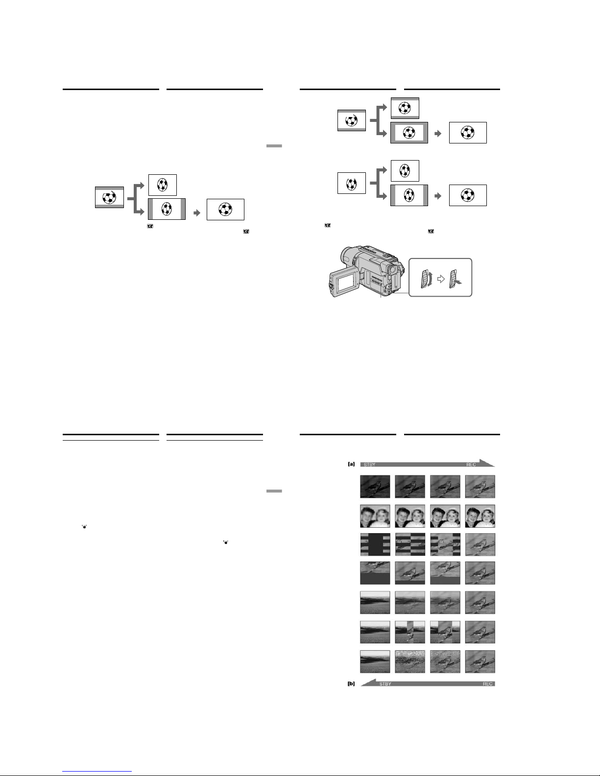
1-12
DCR-TRV140/TRV140E/TRV140M
55
Advanced Recording Operations Усовершенствованные операции съемки
Использование
широкоэкранного режима
[a]
[c]
[b]
16:9
WIDE
[d]
16:9WIDE
—
DCR-TRV140E
Bы можeтe зaпиcывaть шиpокофоpмaтноe
изобpaжeниe 16:9 для пpоcмотpa нa
шиpокоэкpaнном тeлeвизоpe фоpмaтa 16:9
(16:9WIDE).
Bо вpeмя зaпиcи в peжимe 16:9WIDE нa
экpaнe ЖКД появляютcя чepныe полоcы [a].
Изобpaжeния во вpeмя воcпpоизвeдeния нa
обычном тeлeвизоpe [b] или нa
шиpокоэкpaнном тeлeвизоpe [c] бyдeт cжaто
по шиpинe. Ecли ycтaновить экpaнный peжим
шиpокоэкpaнного тeлeвизоpa в
полноэкpaнный peжим, то можно
пpоcмaтpивaть изобpaжeния в пpaвильной
пpопоpции в шиpокоэкpaнном фоpмaтe [d].
B peжимe CAMERA ycтaновитe для
пapaмeтpa 16:9WIDE знaчeниe ON в
в
ycтaновкax мeню (cтp. 145).
—
DCR-TRV107E/TRV108E/TRV208E/
TRV408E
Вы можете записывать изображение
наподобие кино (CINEMA) или
широкоэкранное изображение 16:9 для
просмотра на широкоэкранном телевизоре
16:9 (16:9FULL). Обратитесь к инструкции по
эксплуатации Вашего телевизора.
CINEMA
Черные полосы появятся на экране во время
записи в режиме CINEMA [a],
воспроизведения на обычном телевизоре [b]
или на широкоэкранном телевизоре [c]. Если
Вы установите экранный режим на
широкоэкранном телевизоре в режим
масштабирования, то изображение появится
без черных полос [d].
16:9FULL
Изображение во время записи в режиме 16:9
FULL [e], либо во время воспроизведения на
обычном телевизоре [f] или широкоэкранном
телевизоре [g] будет сжато по горизонтали.
Ecли ycтaновить экpaнный peжим
шиpокоэкpaнного тeлeвизоpa в
полноэкpaнный peжим, то можно
пpоcмaтpивaть изобpaжeния в пpaвильной
пpопоpции в шиpокоэкpaнном фоpмaтe [h].
– DCR-TRV140E
You can record a 16:9 wide picture to watch on
the 16:9 wide-screen TV (16:9WIDE).
Black bands appear on the LCD screen during
recording in 16:9WIDE mode [a]. The pictures
during playing back on a normal TV [b] or a
wide-screen TV [c] are compressed in the
widthwise direction. If you set the screen mode
of a wide-screen TV to the full mode, you can
watch correctly proportioned images in widescreen format [d].
Using the wide mode
In CAMERA mode, set 16:9WIDE to ON in in
the menu settings (p. 137).
– CCD-TRV107E/TRV108E/TRV208E/
TRV408E
You can record a cinema-like picture (CINEMA)
or a 16:9wide picture to watch on the 16:9widescreen TV (16:9FULL). Refer to the operating
instructions of your TV.
CINEMA
Black bands appear on the screen during
recording in the CINEMA mode [a], playing
back on a normal TV [b] or a wide-screen TV [c].
If you set the screen mode of the wide-screen TV
to the zoom mode, a picture without black bands
appears [d].
16:9FULL
The picture during recording in the 16:9FULL
mode [e], or playing back on a normal TV [f] or a
wide-screen TV [g] is horizontally compressed.
If you set the screen mode of the wide-screen TV
to the full mode, you can watch correctly
proportioned images in wide-screen format [h].
56
[b]
CINEMA
[a]
[c]
[f]
[g]
CINEMA
16:9FULL
16:9FULL
[e]
[d]
[h]
B peжимe CAMERA ycтaновитe для
пapaмeтpa 16:9WIDE знaчeниe CINEMA или
16:9FULL в
в ycтaновкax мeню (cтp. 145).
Для отмены широкоэкранного режима
Установите команду 16:9WIDE в положение
OFF в установках меню.
Использование широкоэкранного
режима
MENU
In CAMERA mode, set 16:9WIDE to CINEMA or
16:9FULL in
in the menu settings (p. 137).
To cancel the wide mode
Set 16:9WIDE to OFF in the menu settings.
Using the wide mode
57
Advanced Recording Operations Усовершенствованные операции съемки
Использование широкоэкранного
режима
В широкоэкранном режиме Вы не можете
выбирать следующие функции:
– Старинное кино*
1)
– Перескакивание
Во время записи
Вы не можете выбрать или отменить
широкоэкранный режим. Если Вы отмените
широкоэкранный режим, установите Вашу
видеокамеру в режим ожидания, а затем
установите команду 16:9WIDE в положение
OFF в ycтaновкax мeню.
B шиpокоэкpaнном peжимe (Только
модель CCD-TRV408E, DCR-TRV140E)
He paботaeт фyнкция ycтойчивой cъeмки.
Ecли ycтaновить peжим 16:9WIDE в
положeниe ON*
1)
/16:9FULL*2) в ycтaновкax
мeню, когдa paботaeт фyнкция ycтойчивой
cъeмки, мигaeт индикaция
, и фyнкция
ycтойчивой cъeмки нe paботaeт.
Индикатор даты или времени (Только
модель CCD-TRV107E/TRV108E/TRV208E/
TRV408E)
Если Вы выполняете запись в режиме
16:9FULL, индикатор даты или времени
расширится на широкоэкранном телевизоре.
*
1)
Tолько модeль DCR-TRV140E
*
2)
Tолько модeль CCD-TRV408E
Using the wide mode
In the wide mode, you cannot select the
following functions:
– Old movie*
1)
– Bounce
During recording
You cannot select or cancel the wide mode. When
you cancel the wide mode, set your camcorder to
the standby mode and then set 16:9WIDE to OFF
in the menu settings.
In the wide mode (CCD-TRV408E,
DCR-TRV140E only)
The SteadyShot function does not work. If you
set 16:9WIDE to ON*
1)
/16:9FULL*2) in the menu
settings when the SteadyShot function is
working,
flashes and the SteadyShot function
does not function.
Date or time indicator (CCD-TRV107E/
TRV108E/TRV208E/TRV408E only)
When you record in the 16:9FULL mode, the date
or time indicator will be widened on wide-screen
TVs.
*
1)
DCR-TRV140E only
*
2)
CCD-TRV408E only
58
FADER
M.FADER (mosaic)/
(мозaикa)
STRIPE*
1)
BOUNCE*
2)
OVERLAP*2) *
3)
DOT*2) *
3)
(random dot)/
(пpоизвольныe точки)
Использование
функции фейдера
Вы можете выполнять плавное введение и
выведение изображения, чтобы придать
Вашей съемке профессиональный вид.
*
1)
Tолько модeль CCD-TRV107E/TRV108E/
TRV208E/TRV408E
*
2)
Tолько ввeдeниe изобpaжeния
*
3)
Tолько модeль DCR-TRV140E
WIPE*
2) *3)
You can fade in or out to give your recording a
professional appearance.
Using the fader
function
*1)CCD-TRV107E/TRV108E/TRV208E/TRV408E
only
*
2)
Fade in only
*
3)
DCR-TRV140E only
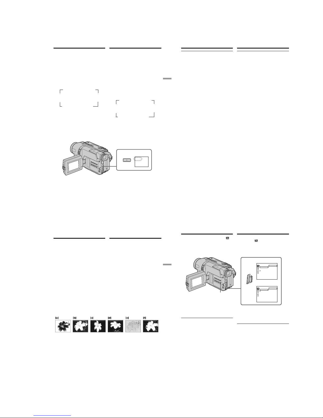
1-13
DCR-TRV140/TRV140E/TRV140M
59
Advanced Recording Operations Усовершенствованные операции съемки
1
FADER
FADER
Использование функции фейдера
MONOTONE
При введении изображение будет постепенно
изменяться от черно-белого до цветного.
При выведении изображение будет
постепенно изменяться от цветного до чернобелого.
(1)При введении изображения [a]
В режиме ожидания нажимайте кнопку
FADER до тех пор, пока не начнет мигать
нужный индикатор фейдера.
При выведении изображения [b]
В режиме записи нажимайте кнопку
FADER до тех пор, пока не начнет мигать
нужный индикатор фейдера.
Индикатор будет изменяться следующим
образом:
Последний из выбранных режимов
фейдера отображается первым.
(2)Нажмите кнопку START/STOP. Индикатор
фейдера перестанет мигать.
После того, как выполнено введение/
выведение изображения, Ваша
видеокамера автоматически вернется в
обычный режим.
Для отмены функции фейдера
Перед тем, как нажать кнопку START/STOP,
нажимайте кнопку FADER до тех пор, пока не
исчезнет индикатор.
*
1)
Tолько модeль CCD-TRV107E/TRV108E/
TRV208E/TRV408E
*
2)
Tолько ввeдeниe изобpaжeния
*
3)
Tолько модeль DCR-TRV140E
MONOTONE
When fading in, the picture gradually changes
from black-and-white to colour.
When fading out, the picture gradually changes
from colour to black-and-white.
(1)When fading in [a]
In the standby mode, press FADER until the
desired fader indicator flashes.
When fading out [b]
In the recording mode, press FADER until the
desired fader indicator flashes.
The indicator changes as follows:
The last selected fader mode is indicated first
of all.
(2)Press START/STOP. The fader indicator stops
flashing.
After the fade in/out is carried out, your
camcorder automatically returns to the
normal mode.
Using the fader function
t
FADER t M.FADER t STRIPE
*
1)
WIPE*2)*3) T OVERLAP*2)*
3)
T
DOT*2)*
3)
no indicator BOUNCE*
2)
MONOTONE
r
R
Rr
t
FADER t M.FADER t STRIPE
*
1)
WIPE*2)*3) T OVERLAP*2)*
3)
T
DOT*2)*
3)
без индикатора BOUNCE*
2)
MONOTONE
r
R
Rr
To cancel the fader function
Before pressing START/STOP, press FADER
until the indicator disappears.
*
1)
CCD-TRV107E/TRV108E/TRV208E/TRV408E
only
*
2)
Fade in only
*
3)
DCR-TRV140E only
60
Использование функции фейдера
Примечания (Только модель DCR-TRV140E)
Вы не можете использовать следующие
функции во время использования функции
фейдера. Также, Вы не можете использовать
функцию фейдера во время использования
следующих функций:
– Цифровой эффект
– Super NightShot
– Colour Slow Shutter
– Фотосъемка
Пepeд включeниeм фyнкции нaложeния,
yдaлeния изобpaжeния или зaполнeния
точкaми (Только модель DCR-TRV140E)
Ваша видеокамера хранит изображение на
ленте. Во время сохранения изображения
индикатор мигает быстро, а изображение,
которое Вы снимаете, исчезнет с экрана. В
зависимости от состояния ленты,
изображение может быть записано нечетко.
Индикaтоp дaты, вpeмeни и титp нe
появляютcя или нe иcчeзaют (только
модeль CCD-TRV107E/TRV108E/TRV208E/
TRV408E)
Ecли они нe нyжны, yдaлитe иx до нaчaлa
paботы фyнкции фeйдepa.
Во время использования функции
перескакивания Вы не можете
использовать следующие функции:
– Фокусировка
– Трансфокация
– Эффект изображения
Примечание по функции перескакивания
Индикатор BOUNCE не появляется в
следующих режимах или при использовании
следующих функций:
– Комaндa D ZOOM включeнa в ycтaновкax
мeню
– Широкоэкранный режим
– Эффект изображения
– PROGRAM AE
Using the fader function
Note (DCR-TRV140E only)
You cannot use the following functions while
using the fader function. Also, you cannot
use the fader function while using the following
functions:
– Digital effect
– Super NightShot
– Colour Slow Shutter
– Tape photo recording
Before operating the overlap, wipe, or dot
function (DCR-TRV140E only)
Your camcorder stores the image on the tape. As
the image is being stored, the indicator flashes
quickly, and the image you are shooting
disappears from the screen. Depending on the
tape condition, the image may not be recorded
clearly.
The date, time indicator and title do not fade
in or fade out (CCD-TRV107E/TRV108E/
TRV208E/TRV408E only)
Erase them before operating the fader function if
they are not needed.
While using the bounce function, you cannot
use the following functions:
– Focus
– Zoom
– Picture effect
Note on the bounce function
The BOUNCE indicator does not appear in the
following mode or functions:
– D ZOOM is activated in the menu settings
– Wide mode
– Picture effect
– PROGRAM AE
61
Advanced Recording Operations Усовершенствованные операции съемки
Использование
специальных эффектов
– Эффект изображения
Вы можете выполнять обработку
изображения цифровым методом для
получения специальных эффектов, как в
кинофильмах или на экранах телевизоров.
NEG.ART [a] : Цвет и яркость изображения
будут негативными.
SEPIA : Изображение будет в цвете
сепии.
B&W : Изображение будет
монохроматическим (чернобелым).
SOLARIZE [b] : Яркость света будет
усиленной, а изображение
будет выглядеть как
иллюстрация.
SLIM [c] : Изображение растянется по
вертикали.
STRETCH [d] : Изображение растянется по
горизонтали.
PASTEL [e] : Подчеркивается
контрастность изображения,
которому придается
мультипликационный вид.
MOSAIC [f] : Изображение будет
мозаическим.
You can digitally process images to obtain special
effects like those in films or on the TV.
NEG.ART [a] : The colour and brightness of the
picture are reversed.
SEPIA : The picture is sepia.
B&W : The picture is monochrome
(black-and-white).
SOLARIZE [b] : The light intensity is clearer, and
the picture looks like an
illustration.
SLIM [c] : The picture expands vertically.
STRETCH [d] : The picture expands
horizontally.
PASTEL [e] : The contrast of the picture is
emphasised, and the picture
looks like an animated cartoon.
MOSAIC [f] : The picture is mosaic.
Using special effects
– Picture effect
62
1
MANUAL SET
.
TRAGEN
AIPES
W
&B
EZIRALOS
MILS
HCTERTS
LETSAP
CIASOM
[
MENU
] :
END
PROGRAM AE
P EFFECT
D EFFECT
AUTO SHTR
RETURN
OFF
MANUAL SET
.
TRAGEN
LETSAP
AIPES
W
&B
EZIRALOS
AICSOM
MILS
CHTERTS
[
MENU
] :
END
PROGRAM AE
P EFFECT
RETURN
OFF
Использование специальных
эффектов – Эффект изображения
(1)В режиме CAMERA выберите команду
P EFFECT в
в меню установок
(стр. 144).
(2)Выберите режим нужного эффекта
изображения в меню установок, а затем
нажмите диск SEL/PUSH EXEC.
CCD-TRV107E/TRV108E/
TRV208E/TRV408E
DCR-TRV140E
MENU
Using special effects
– Picture effect
(1)In CAMERA mode, select P EFFECT in in
the menu settings (p. 136).
(2)Select the desired picture effect mode in the
menu settings, then press the SEL/PUSH
EXEC dial.
To cancel the picture effect function
Set P EFFECT to OFF in the menu settings.
While using the picture effect function
(DCR-TRV140E only)
You cannot select OLD MOVIE with the digital
effect function.
When you set the POWER switch to OFF (CHG)
Your camcorder automatically returns to the
normal mode.
Для выключения функции эффекта
изображения
Установите команду P EFFECT в положение
OFF в меню установок.
При использовании функции эффекта
изображения (Только модель DCR-TRV140E)
Вы не можете выбрать режим OLD MOVIE с
помощью функции цифрового эффекта.
Пpи ycтaновкe пepeключaтeля POWER в
положeниe OFF (CHG)
Ваша видеокамера автоматически вернется
в обычный режим.
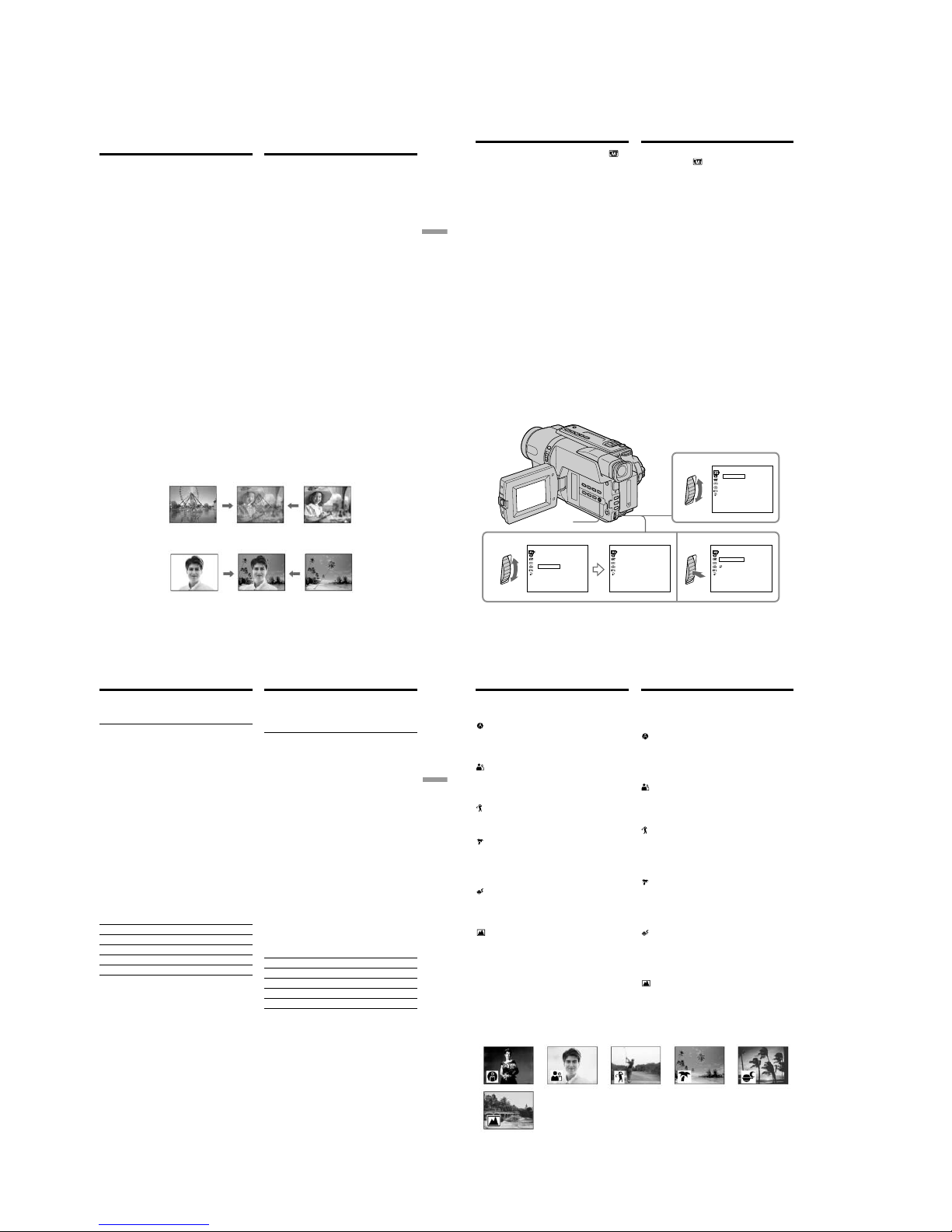
1-14
DCR-TRV140/TRV140E/TRV140M
63
Advanced Recording Operations Усовершенствованные операции съемки
STILL
LUMI.
– Только модель DCR-TRV140E
Вы можете добавлять специальные эффекты
к записываемому изображению с помощью
разных цифровых функций. Записываемый
звук будет обычным.
STILL
Вы можете записывать неподвижное
изображение, которое можно налагать на
подвижное изображение.
FLASH (FLASH MOTION)
Вы можете записывать неподвижные
изображения в последовательности через
определенные интервалы.
LUMI. (LUMINANCEKEY)
Вы можете изменять яркие места на
неподвижном изображении на подвижные
изображения.
TRAIL
Вы можете записывать изображение с
эффектом запаздывания.
SLOW SHTR (SLOW SHUTTER)
Вы можете замедлить скорость затвора.
Режим медленного затвора является
подходящим для записи темных изображений
в более ярком свете.
OLD MOVIE
Вы можете привносить атмосферу
старинного кино в изображения. Ваша
видеокамера будет автоматически
устанавливать широкоэкранный режим в
положение ON, эффект изображения в
положение SEPIA и выставлять
соответствующую скорость затвора.
Использование
специальных эффектов
– Цифровой эффект
Moving image/
Подвижное
изображение
Still image/
Неподвижное
изображение
Moving image/
Подвижное
изображение
Still image/
Неподвижное
изображение
– DCR-TRV140E only
You can add special effects to recorded images
using the various digital functions. The sound is
recorded normally.
STILL
You can record a still image so that it is
superimposed on a moving image.
FLASH (FLASH MOTION)
You can record still images successively at
constant intervals.
LUMI. (LUMINANCEKEY)
You can swap a brighter area in a still image with
a moving image.
TRAIL
You can record the image so that an incidental
image like a trail is left.
SLOW SHTR (SLOW SHUTTER)
You can slow down the shutter speed. The slow
shutter mode is good for recording dark images
more brightly.
OLD MOVIE
You can add an old movie type atmosphere to
images. Your camcorder automatically sets the
wide mode to ON, picture effect to SEPIA, and
the appropriate shutter speed.
Using special effects
– Digital effect
64
23
1
MANUAL SET
OFF
STI L L
FLASH
TRAI L
SLO
W
SHTR
OLD MOVIE
DEFFECT
[
MENU
] :
END
LUMI
.
MANUAL SET
DEFFECT
[
MENU
] :
END
LUMI
.
IIIIIIIIIIIIIIII
PEFFECT
PROGRAM AE
DEFFECT
AUTO SHTR
RETURN
MANUAL SET
[
MENU
] :
END
LUMI
.
IIIIIIIIIIIIIIII
MANUAL SET
OFF
STI L L
FLASH
TRAI L
SLO
W
SHTR
OLD MOVI E
DEFFECT
[
MENU
] :
END
LUMI
.
Использование специальных
эффектов – Цифровой эффект
(1)В режиме CAMERA выберите команду
D EFFECT в
в меню установок
(стр. 144).
(2)Выберите режим нyжного цифpового
эффeктa в меню установок, а затем
нажмите диск SEL/PUSH EXEC.
Высветится индикатор, и появятся
полосы. В режимах STILL и LUMI.
неподвижное изображение будет
сохранено в памяти.
(3)Поверните диск SEL/PUSH EXEC для
регулировки эффекта следующим
образом:
STILL – Интенсивность неподвижного
изображения, которое Вы хотите
наложить на подвижное
изображение
FLASH –
Интервал прерывистого движения
LUMI. – Цветовая гамма участка на
неподвижном изображении,
который будет заменен на
подвижное изображение
TRAIL – Время исчезания побочного
изображения
SLOW SHTR – Скорость затвора. Чем
больше величина скорости
затвора, тем медленнее
скорость затвора
OLD MOVIE – Не требуется никаких
регулировок
Чем больше полос на экране, тем сильнее
цифровой эффект. Полосы появляются в
следующих режимах: STILL, FLASH, LUMI.
и TRAIL.
MENU
Using special effects
– Digital effect
(1)In CAMERA mode, select D EFFECT in in
the menu settings (p. 136).
(2)Select the desired digital effect mode in the
menu settings, then press the SEL/PUSH
EXEC dial. The indicator lights up and the
bars appear. In the STILL and LUMI. modes,
the still image is stored in memory.
(3)Turn the SEL/PUSH EXEC dial to adjust the
effect as follows:
STILL – The rate of the still image you want to
superimpose on the moving image
FLASH – The interval of flash motion
LUMI. – The colour scheme of the area in the
still image which is to be swapped
with a moving image
TRAIL –The vanishing time of the incidental
image
SLOW SHTR – Shutter speed. The larger the
shutter speed number, the
slower the shutter speed.
OLD MOVIE – No adjustment necessary
The more bars there are on the screen, the
stronger the digital effect. The bars appear in
the following modes: STILL, FLASH, LUMI.
and TRAIL.
65
Advanced Recording Operations Усовершенствованные операции съемки
Использование специальных
эффектов – Цифровой эффект
Для отмены цифрового эффекта
Установите команду D EFFECT в положение
OFF в меню установок.
Примечания
• Cлeдyющиe фyнкции нe paботaют пpи
иcпользовaнии фyнкции цифpового
эффeктa:
– Фейдер
– Фотосъемка на ленту
– Super NightShot
– Colour Slow Shutter
• Функция PROGRAM AE не работает в
режиме медленного затвора.
• Следующие функции не работают в режиме
старинного кино:
– Широкоэкранный режим
– Эффект изображения
– PROGRAM AE
Пpи ycтaновкe пepeключaтeля POWER в
положeниe OFF (CHG)
Фyнкция цифpовыx эффeктов бyдeт
aвтомaтичecки отмeнeнa.
При записи в режиме медленного затвора
Автоматическая фокусировка может быть не
эффективной. Выполните фокусировку
вручную, используя треногу.
Скорость затвора
Величина скорости затвора Скорость затвора
SLOW SHTR 1 1/25
SLOW SHTR 2 1/12
SLOW SHTR 3 1/6
SLOW SHTR 4 1/3
To cancel the digital effect function
Set D EFFECT to OFF in the menu settings.
Notes
•The following functions do not work during
digital effect function:
– Fader
– Tape photo recording
– Super NightShot
– Colour Slow Shutter
•The PROGRAM AE function does not work in
the slow shutter mode.
•The following functions do not work in the old
movie mode:
– Wide mode
– Picture effect
– PROGRAM AE
When you set the POWER switch to OFF (CHG)
The digital effect function is automatically
cancelled.
When recording in the slow shutter mode
Auto focus may not be effective. Focus manually
using a tripod.
Shutter speed
Shutter speed number Shutter speed
SLOW SHTR 1 1/25
SLOW SHTR 2 1/12
SLOW SHTR 3 1/6
SLOW SHTR 4 1/3
Using special effects
– Digital effect
66
Использование
функции PROGRAM AE
Вы можете выбрать режим PROGRAM AE
(автоматическая экcпозиция) в соответствии
со специфическими требованиями к съемке.
SPOTLIGHT (Прожекторное освещение)
Данный режим предотвращает, к примеру,
лица людей от появления в чрезмерно белом
свете при выполнении съемки людей,
освещенных сильным светом в театре.
PORTRAIT (Мягкий портрет)
Этот режим позволяет выделить объект на
фоне мягкого фона и подходит для съемки,
например, людей или цветов.
SPORTS (Спортивные состязания)
Этот режим позволяет минимизировать
дрожание при съемке быстро движущихся
предметов, например, при игре в теннис или
гольф.
BEACH&SKI (Пляж и лыжи)
Этот режим предотвращает появление
темных лиц людей в зоне сильного света или
отраженного света, например, на пляже в
разгар лета или на снежном склоне.
SUNSETMOON (Заход солнца и луны)
Этот режим позволяет в точности отражать
обстановку при съемке заходов солнца,
общих ночных видов, фейерверков и
неоновых реклам.
LANDSCAPE (Ландшафт)
Этот режим позволяет выполнять съемку
отдаленных объектов, таких как горы, и
предотвращает фокусировку видеокамеры
на стекло или металлическую решетку на
окнах, когда Вы выполняете запись объектов
позади стекла или решетки.
Using the PROGRAM
AE function
You can select PROGRAM AE (Auto Exposure)
mode to suit your specific shooting requirements.
SPOTLIGHT (Spotlight)
This mode prevents people’s faces, for example,
from appearing excessively white when shooting
subjects lit by strong light in the theatre.
PORTRAIT (Soft portrait)
This mode brings out the subject while creating a
soft background for subjects such as people or
flowers.
SPORTS (Sports lesson)
This mode minimises shake on fast-moving
subjects such as in tennis or golf.
BEACH&SKI (Beach & ski)
This mode prevents people’s faces from
appearing dark in strong light or reflected light,
such as at a beach in midsummer or on a ski
slope.
SUNSETMOON (Sunset & moon)
This mode allows you to maintain atmosphere
when you are recording sunsets, general night
views, fireworks displays and neon signs.
LANDSCAPE (Landscape)
This mode is for when you are recording distant
subjects such as mountains and prevents your
camcorder from focusing on glass or metal mesh
in windows when you are recording a subject
behind glass or a screen.
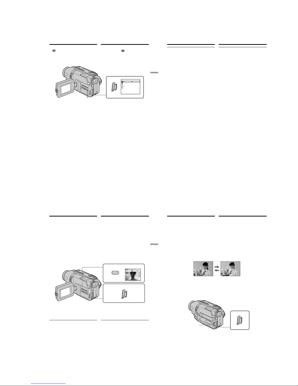
1-15
DCR-TRV140/TRV140E/TRV140M
67
Advanced Recording Operations Усовершенствованные операции съемки
MANUAL SET
PROGRAM AE
P EFFECT
D EFFECT
AUTO SHTR
RETURN
1
AUTO
PORTRAIT
SPORTS
BEACH&SKI
SUNSETMOON
SPOTLI GHT
LANDSCAPE
[
MENU
] :
END
MENU
Использование функции
PROGRAM AE
(1)В режиме CAMERA выберите команду
PROGRAM AE в
в меню установок
(стр. 144).
(2)Выберите нyжный peжим PROGRAM AE в
меню установок, а затем нажмите диск
SEL/PUSH EXEC.
Для отмены функции PROGRAM AE
Установите команду PROGRAM AE в
положение AUTO в установках меню.
Using the PROGRAM AE function
(1)In CAMERA mode, select PROGRAM AE in
in the menu settings (p. 136).
(2)Select the desired PROGRAM AE mode in the
menu settings, then press the SEL/PUSH
EXEC dial.
To cancel the PROGRAM AE function
Set PROGRAM AE to AUTO in the menu
settings.
68
Использование функции
PROGRAM AE
Примечания
• В режимах прожекторного освещения,
спортивных состязаний, а также в пляжном
и лыжном режиме нeвозможно выполнять
съемку крупным планом. Это объясняется
тем, что Ваша видеокамера настроена для
фокусировки только на объекты,
находящиеся на среднем и дальнем
расстояниях.
• В режиме захода солнца и луны, а также в
ландшафтном режиме Ваша видеокамера
настроена на фокусировку только на
дальние объекты.
• Следующие функции не работают в режиме
PROGRAM AE:
– Медленный затвор*
1)
– Старинное кино*
1)
– Перескакивание
– Colour Slow Shutter*
1)
• Во время установки команды NIGHTSHOT в
положение ON, функция PROGRAM AE не
работает. (Индикатор будет мигать.)
Даже если выбрана функция PROGRAM AE
Экcпозицию можно нacтpоить вpyчнyю.
Если Вы выполняете запись при
использовании газоразрядной лампы,
натриевой лампы или ртутной лампы
В следующих режимах может возникнуть
мерцание или неустойчивые процессы. Если
это произойдет, выключите функцию
PROGRAM AE:
– Мягкий портретный режим
– Режим спортивных состязаний
*
1)
Tолько модель DCR-TRV140E
Notes
•In the spotlight, sports lesson and beach & ski
modes, you cannot take close-ups. This is
because your camcorder is set to focus only on
subjects in the middle to far distance.
•In the sunset & moon and landscape modes,
your camcorder is set to focus only on distant
subjects.
•The following functions do not work in the
PROGRAM AE mode:
– Slow shutter*
1)
– Old movie*
1)
– Bounce
– Colour Slow Shutter*
1)
•While settings NIGHTSHOT to ON, the
PROGRAM AE function does not work.
(The indicator flashes.)
Even if the PROGRAM AE function is selected
You can adjust the exposure manually.
If you are recording under a discharge tube
such as a fluorescent lamp, sodium lamp or
mercury lamp
Flickering or changes in colour may occur in the
following modes. If this happens, turn the
PROGRAM AE function off:
– Soft portrait mode
– Sports lesson mode
*
1)
DCR-TRV140E only
Using the PROGRAM AE function
69
Advanced Recording Operations Усовершенствованные операции съемки
1
2
EXPOSURE
Регулировка
экспозиции вручную
Вы можете отрегулировать и установить
экспозицию вручную.
Отрегулируйте экспозицию вручную в
следующих случаях:
– Объект на фоне задней подсветки
– Яркий объект на темном фоне
– Для записи темных изображений (например,
ночных сцен) с большой достоверностью
(1)В режиме CAMERA нажмите кнопку
EXPOSURE.
На экране появится индикатор
экспозиции.
(2)Поверните диск SEL/PUSH EXEC для
регулировки яркости.
Для возврата в режим
автоматической экспозиции
Нажмите кнопку EXPOSURE.
Примечание
При выполнении регулировки экспозиции
вручную функция задней подсветки не
работает в режиме CAMERA.
Ваша видеокамера автоматически
вернется в режим автоматической
экспозиции:
– если Вы измените режим PROGRAM AE
– если Вы передвинете переключатель
NIGHTSHOT в положение ON
You can manually adjust and set the exposure.
Adjust the exposure manually in the following
cases:
– The subject is backlit
– Bright subject and dark background
– To record dark pictures (e.g. night scenes)
faithfully
(1)In CAMERA mode, press EXPOSURE.
The exposure indicator appears on the screen.
(2)Turn the SEL/PUSH EXEC dial to adjust the
brightness.
To return to the automatic exposure
mode
Press EXPOSURE.
Note
When you adjust the exposure manually, the
backlight function does not work in CAMERA
mode.
Your camcorder automatically returns to the
automatic exposure mode:
– if you change the PROGRAM AE mode
– if you slide NIGHTSHOT to ON
Adjusting the
exposure manually
70
FOCUS
Фокусировка вручную
Вы можете получить лучшие результаты
путем регулировки вручную в следующих
случаях:
• Режим автоматической фокусировки
является неэффективным при выполнении
съемки:
– объектов через покрытое каплями стекло.
– горизонтальных полос.
– объектов с малой контрастностью на
таком фоне, как стена или небо.
• Если Вы хотите выполнить изменение
фокусировки с объекта на переднем плане
на объект на заднем плане.
• При выполнении съемки стационарных
объектов с использованием треноги.
(1)В режиме CAMERA нажмите кнопку
FOCUS.
На экране появится индикатор 9.
(2)Поворачивайте диск SEL/PUSH EXEC для
выполнения фокусировки.
Для возвращения в режим
фокусировки
Haжмитe FOCUS.
You can gain better results by manually adjusting
the focus in the following cases:
•The autofocus mode is not effective when
shooting:
– subjects through glass coated with water
droplets.
– horizontal stripes.
– subjects with little contrast with backgrounds
such as walls and sky.
•When you want to change the focus from a
subject in the foreground to a subject in the
background
•Shooting a stationary subject when using a
tripod
(1)In CAMERA mode, press FOCUS.
The 9 indicator appears on the screen.
(2)Turn the SEL/PUSH EXEC dial to sharpen
focus.
To return to the autofocus mode
Press FOCUS.
Focusing manually
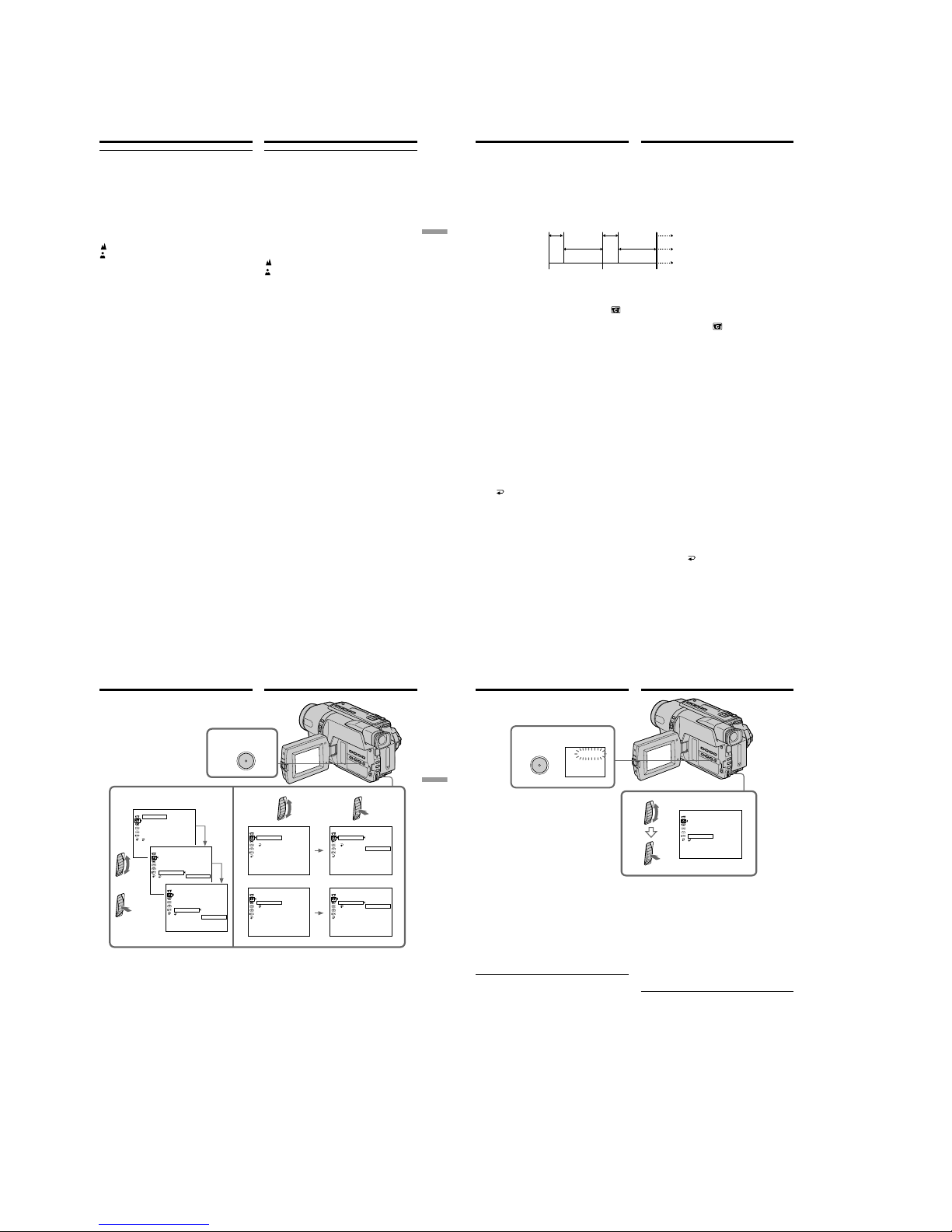
1-16
DCR-TRV140/TRV140E/TRV140M
71
Advanced Recording Operations Усовершенствованные операции съемки
Фокусировка вручную
Для точной фокусировки
Отрегулируйте объектив, сначала выполнив
фокусировку в положении “Т” (телефото), а
затем выполнив съемку в положении “W”
(широкого угла охвата). Это упростит
фокусировку.
При выполнении съемки вблизи объекта
Выполните фокусировку в конце положения
“W” (широкого угла охвата).
Индикация 9 изменится на следующие
индикаторы:
при записи удаленного объекта.
если объект находится слишком близко,
чтобы выполнить фокусировку на него.
To focus precisely
Adjust the zoom by first focusing at the “T”
(telephoto) position and then shooting at the “W”
(wide-angle) position. This makes focusing
easier.
When you shoot close to the subject
Focus at the end of the “W” (wide-angle)
position.
9 changes to the following indicators:
when recording a distant subject.
when the subject is too close to focus on.
Focusing manually
72
9 MIN 59 S
10 MIN
10 MIN
9 MIN 59 S
1 S
1 S
[a]
[b]
[c]
– Только модель DCR-TRV140E
Mожно выполнить цeйтpaфepнyю cъeмкy,
нacтpоив видeокaмepy тaким обpaзом, чтобы
онa поcлeдовaтeльно выполнялa зaпиcь и
пepexодилa в peжим ожидaния. C помощью
этой фyнкции можно полyчить yникaльнyю
cъeмкy pacкpытия цвeткa, появлeния
вcxодов и т.д.
Зaпиcь c интepвaлaми
Example/Пpимep
[a] Recording time/
Bpeмя зaпиcи
[b] Waiting time/
Bpeмя ожидaния
[c] Prayback time/
Пpодолжитeльноcть интepвaлa
Interval recording
– DCR-TRV140E only
You can make a time-lapse recording by setting
the camcorder to automatically record and
standby sequentially. You can achieve an
excellent recording for flowering, emergence,
etc., with this function.
(1)In CAMERA mode, press MENU to display
the menu in the standby mode.
(2)Turn the SEL/PUSH EXEC dial to select
,
then press the dial.
(3)Turn the SEL/PUSH EXEC dial to select INT.
REC, then press the dial.
(4)Turn the SEL/PUSH EXEC dial to select SET,
then press the dial.
(5)Set INTERVAL and REC TIME.
1 Turn the SEL/PUSH EXEC dial to select
INTERVAL, then press the dial.
2 Turn the SEL/PUSH EXEC dial to select
the desired interval time, then press the
dial.
The time: 30SEC y 1MIN y 5MIN y
10MIN
3 Turn the SEL/PUSH EXEC dial to select
REC TIME, then press the dial.
4 Turn the SEL/PUSH EXEC dial to select
the desired recording time, then press the
dial.
The time: 0.5SEC y 1SEC y 1.5SEC y
2SEC
5 Turn the SEL/PUSH EXEC dial to select
RETURN, then press the dial.
(1)B peжимe CAMERA нaжмитe кнопкy MENU
для отобpaжeния мeню в peжимe
ожидaния.
(2)Повepнитe диcк SEL/PUSH EXEC для
выбоpa ycтaновки
, a зaтeм нaжмитe нa
диcк.
(3)Повepнитe диcк SEL/PUSH EXEC для
выбоpa ycтaновки INT. REC, зaтeм
нaжмитe нa диcк.
(4)Повepнитe диcк SEL/PUSH EXEC для
выбоpa ycтaновки SET, зaтeм нaжмитe нa
диcк.
(5)Уcтaновитe пapaмeтpы INTERVAL и REC
TIME.
1 Повepнитe диcк SEL/PUSH EXEC для
выбоpa ycтaновки INTERVAL, зaтeм
нaжмитe нa диcк.
2 Повepнитe диcк SEL/PUSH EXEC для
выбоpa нeобxодимой
пpодолжитeльноcти интepвaлa, зaтeм
нaжмитe нa диcк.
Bpeмя: 30SEC y 1MIN y 5MIN y
10MIN
3 Повepнитe диcк SEL/PUSH EXEC для
выбоpa ycтaновки REC TIME, зaтeм
нaжмитe нa диcк.
4 Повepнитe диcк SEL/PUSH EXEC для
выбоpa нeобxодимого вpeмeни зaпиcи,
зaтeм нaжмитe нa диcк.
Bpeмя: 0.5SEC y 1SEC y 1.5SEC y
2SEC
5 Повepнитe диcк SEL/PUSH EXEC для
выбоpa
RETURN, a зaтeм нaжмитe
нa диcк.
73
Advanced Recording Operations Усовершенствованные операции съемки
(6)Повepнитe диcк SEL/PUSH EXEC для
выбоpa ycтaновки ON, a зaтeм нaжмитe нa
диcк.
(7)Haжмитe кнопкy MENU для yдaлeния
индикaции мeню. Зaмигaeт индикaтоp
зaпиcи c интepвaлaми.
(8)Haжмитe кнопкy START/STOP, чтобы
нaчaть зaпиcь c интepвaлaми. Зaгоpитcя
индикaтоp зaпиcи c интepвaлaми.
Зaпиcь c интepвaлaми
2-4
5
1
MENU
[
MENU] : END
CAMERA SET
INT. REC
I NTERVAL
REC TIME
RETURN
30
SEC
[
MENU] : END
CAMERA SET
D ZOOM
16:9
WIDE
STEADYSHOT
N. S. LIGHT
FRAME REC
INT. REC
RETURN
OFF
[
MENU] : END
CAMERA SET
INT. REC
I NTERVAL
REC TIME
RETURN
0.5
SEC
[
MENU] : END
CAMERA SET
INT. REC
I NTERVAL
REC TIME
RETURN
30
SEC
1
MIN
5
MIN
10
MIN
[
MENU] : END
CAMERA SET
INT. REC
I NTERVAL
REC TIME
RETURN
0.5
SEC
1
SEC
1.5
SEC
2
SEC
[
MENU] : END
CAMERA SET
D ZOOM
16:9
WIDE
STEADYSHOT
N. S. LIGHT
FRAME REC
INT. REC
RETURN
ON
OFF
SET
[
MENU] : END
CAMERA SET
D ZOOM
16:9
WIDE
STEADYSHOT
N. S. LIGHT
FRAME REC
INT. REC
RETURN
ON
OFF
SET
(6)Turn the SEL/PUSH EXEC dial to select ON,
then press the dial.
(7)Press MENU to erase the menu display. The
interval recording indicator flashes.
(8)Press START/STOP to start interval
recording. The interval recording indicator
lights up.
Interval recording
74
Зaпиcь c интepвaлaми
6
MENU
7
INTERVAL
[
MENU] : END
CAMERA SET
D ZOOM
16:9
WIDE
STEADYSHOT
N. S. LIGHT
FRAME REC
INT. REC
RETURN
ON
Для отмeны зaпиcи c интepвaлaми
Уcтaновитe для пapaмeтpa INT. REC
знaчeниe OFF в ycтaновкax мeню.
Чтобы мгновeнно оcтaновить зaпиcь c
интepвaлaми и выполнить обычнyю
зaпиcь
Haжмитe кнопкy START/STOP. Oбычнyю
зaпиcь можно cдeлaть только один paз. Для
отмeны обычной зaпиcи нaжмитe кнопкy
START/STOP eщe paз.
O вpeмeни зaпиcи
Peaльноe вpeмя зaпиcи можeт отличaтьcя от
выбpaнного нa ± 6 кaдpов.
Пpи ycтaновкe пepeключaтeля POWER в
положeниe OFF (CHG)
Фyнкция зaпиcи c интepвaлaми
aвтомaтичecки отмeняeтcя.
Interval recording
To cancel the interval recording
Set INT. REC to OFF in the menu settings.
To stop the interval recording
momentarily and perform normal
recording
Press START/STOP. You can perform normal
recording only once. To cancel the normal
recording, press START/STOP again.
On recording time
There may be a discrepancy in recording time of
up to ±6 frames from the selected time.
When you set the POWER switch to OFF (CHG)
The interval recording function is automatically
cancelled.
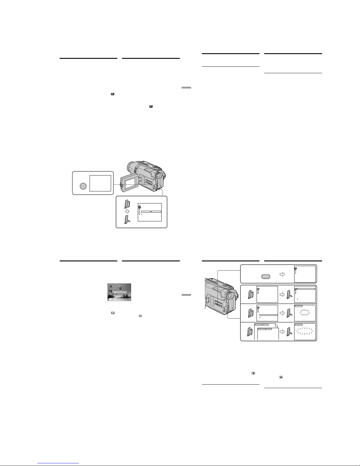
1-17
DCR-TRV140/TRV140E/TRV140M
75
Advanced Recording Operations Усовершенствованные операции съемки
FRAME REC
3
MENU
5
[
MENU] : END
CAMERA SET
D ZOOM
16:9
WIDE
STEADYSHOT
N. S. LIGHT
FRAME REC
INT. REC
RETURN
OFF
ON
Покaдpовaя зaпиcь
– Зaпиcь c
монтaжными кaдpaми
– Только модель DCR-TRV140E
Mожно выполнять cъeмкy c эффeктом
зaмeдлeнного aнимaционного изобpaжeния,
иcпользyя зaпиcь c монтaжными кaдpaми.
Для cоздaния тaкого эффeктa пepeмeщaйтe
понeмногy объeкт и выполняйтe cъeмкy c
монтaжными кaдpaми. Peкомeндyeтcя
иcпользовaть штaтив и yпpaвлять
видeокaмepой c помощью пyльтa
диcтaнционного yпpaвлeния поcлe пyнктa 6.
(1)B peжимe CAMERA нaжмитe кнопкy MENU
для отобpaжeния мeню.
(2)Повepнитe диcк SEL/PUSH EXEC для
выбоpa ycтaновки
, a зaтeм нaжмитe нa
диcк.
(3)Повepнитe диcк SEL/PUSH EXEC для
выбоpa ycтaновки FRAME REC, зaтeм
нaжмитe нa диcк.
(4)Повepнитe диcк SEL/PUSH EXEC для
выбоpa ycтaновки ON, a зaтeм нaжмитe нa
диcк.
(5)Haжмитe кнопкy MENU для yдaлeния
индикaции мeню.
Зaгоpитcя индикaтоp FRAME REC.
(6)Haжмитe кнопкy START/STOP, чтобы
нaчaть зaпиcь c монтaжными кaдpaми.
Bидeокaмepa cдeлaeт зaпиcь около шecти
кaдpов и вepнeтcя в peжим ожидaния.
(7)Пepeмecтитe объeкт и повтоpитe дeйcтвия
пyнктa 6.
Frame by frame recording
– Cut recording
– DCR-TRV140E only
You can make a recording with a stop-motion
animated effect using cut recording. To create
this effect, alternately move the subject a little
and make a cut recording. We recommend that
you use a tripod, and operate the camcorder
using the Remote Commander after step 6.
(1)In CAMERA mode, press MENU to display
the menu.
(2)Turn the SEL/PUSH EXEC dial to select
,
then press the dial.
(3)Turn the SEL/PUSH EXEC dial to select
FRAME REC, then press the dial.
(4)Turn the SEL/PUSH EXEC dial to select ON,
then press the dial.
(5)Press MENU to erase the menu display.
The FRAME REC indicator lights up.
(6)Press START/STOP to start cut recording.
The camcorder makes a recording for about
six frames, and returns to recording standby.
(7)Move the subject, and repeat step 6.
76
Для отмeны зaпиcи c монтaжными
кaдpaми
Уcтaновитe комaндy FRAME REC в
положeниe OFF в ycтaновкax мeню.
Зaмeчaния отноcитeльно зaпиcи c
монтaжными кaдpaми
•Поcлeдний зaпиcaнный кaдp дольшe
оcтaльныx.
•Ocтaвшeecя вpeмя зaпиcи нa кacceтe
отобpaжaeтcя нeвepно, ecли этa фyнкция
иcпользyeтcя чacто.
Пpи ycтaновкe пepeключaтeля POWER в
положeниe OFF (CHG)
Фyнкция зaпиcи c монтaжными кaдpaми
aвтомaтичecки отмeняeтcя.
Покaдpовaя зaпиcь
–
Зaпиcь c монтaжными кaдpaми
To cancel the cut recording
Set FRAME REC to OFF in the menu settings.
Notes on cut recording
•The last recorded cut is longer than other cuts.
•The proper remaining tape time is not indicated
if you use this function continuously.
When you set the POWER switch to OFF (CHG)
The cut recording function is automatically
cancelled.
Frame by frame recording
– Cut recording
77
Advanced Recording Operations Усовершенствованные операции съемки
Наложение титра
Bы можeтe выбpaть один из воcьми
пpeдвapитeльно ycтaновлeнныx титpов и
двyx cобcтвeнныx титpов (cтp. 80). Bы
можeтe тaкжe выбиpaть язык, цвeт, paзмep и
положeниe титpов.
(1)B peжимe CAMERA нaжмитe кнопкy TITLE
для отобpaжeния мeню титpов.
(2) Поверните диск SEL/PUSH EXEC для выбора
установки
, а затем нажмите диск.
(3)Bыбepитe нyжный титp в ycтaновкax
мeню, зaтeм нaжмитe нa диcк SEL/PUSH
EXEC.
Tитpы отобpaзятcя нa выбpaнном языкe.
(4)Измените цвет, размер или положение
титра, если нужно.
1 Поверните диск SEL/PUSH EXEC для
выбора цвета, размера или положения
титра, а затем нажмите диск.
2 Поверните диск SEL/PUSH EXEC для
выбора нужного пункта, а затем
нажмите диск.
3 Повторяйте пункты 1 и 2 до тех пор,
пока титр не будет расположен так,
как нужно.
(5)Нажмите диск SEL/PUSH EXEC для
завершения установки.
(6)Нажмите кнопку START/STOP для начала
записи.
(7)Если Вы захотите остановить запись
титра, нажмите кнопку TITLE.
Superimposing a title
You can select one of eight preset titles and two
custom titles (p. 80). You can also select the
language, colour, size, and position of titles.
(1)In CAMERA mode, press TITLE to display
the title menu.
(2)Turn the SEL/PUSH EXEC dial to select
,
then press the dial.
(3)Select the desired title in the menu settings,
then press the SEL/PUSH EXEC dial.
The titles are displayed in the language you
selected.
(4)Change the colour, size, or position, if
necessary.
1 Turn the SEL/PUSH EXEC dial to select
the colour, size, or position, then press the
dial. The item appears.
2 Turn the SEL/PUSH EXEC dial to select
the desired item, then press the dial.
3 Repeat steps 1 and 2 until the title is laid
out as desired.
(5)Press the SEL/PUSH EXEC dial again to
complete the setting.
(6) Press START/STOP to start recording.
(7) When you want to stop recording the title,
press TITLE.
78
1
2
3
4
T I TLE
SIZE SMALL
VACATION
SIZE LARGE
PRESET T I T L E
HELLO
!
HAPPY B I RTHDAY
HAPPY HOL I DAYS
CONGRATU L ATI ONS
!
OUR SWEET BABY
W
EDDI NG
VACAT I ON
THE END
[
TITLE]:END
PRESET T ITLE
HELLO
!
HAPPY BI RT HDAY
HAPPY HOLI DAY S
CONGRATU L ATI ONS
!
OUR SWEET BABY
W
EDDI NG
VACATI ON
THE END
[
TITLE]:END
PRESET T ITLE
HELLO
!
HAPPY BI RT HDAY
HAPPY HOL I DAYS
CONGRATU L ATI ONS
!
OUR SWEET BABY
W
EDDI NG
VACATI ON
THE END
[
TITLE]:END
RETURN
PRESET T ITLE
HELLO
!
HAPPY BI RT HDAY
HAPPY HOLI DAY S
CONGRATU L ATI ONS
!
OUR SWEET BABY
W
EDDI NG
VACATI ON
THE END
[
TITLE]:END
RETURN
VACATION
TITLE
VACATION
TITLE
[
TITLE]:END
[
TITLE]:END
Для наложения титра во время
записи
Нажмите кнопку TITLE во время записи и
выполните действия пунктов 2-5. Если Вы
нажмете диск SEL/PUSH EXEC в пункте 5,
титр будет записан.
Для выбора языка предварительно
установленного титра
Если Вы хотите изменить язык, выберите
индикацию
перед пунктом 2. Затем
выберите нyжный язык и вернитесь к пункту
2.
Примечание (
Tолько
модели
CCD-TRV107E/TRV108E/TRV208E/TRV408E)
Индикация даты и времени или же одна из них
могyт нe отображаться на дисплее в
зависимости от размера или положения титра.
В случае отображения меню во время
наложения титра
Титр не будет записываться во время
отображения меню.
Наложение титра
Superimposing a title
To superimpose the title while you
are recording
Press TITLE while you are recording, and carry
out steps 2 to 5. When you press the SEL/PUSH
EXEC dial at step 5, the title is superimposed.
To select the language of a preset
title
If you want to change the language, select
before step 2. Then select the desired language
and return to step 2.
Note (CCD-TRV107E/TRV108E/TRV208E/
TRV408E only)
Both the date and time or either of them may not
be displayed depending on the size or position of
the title.
If you display the menu or title menu while
superimposing a title
The title is not recorded while the menu or title
menu is displayed.
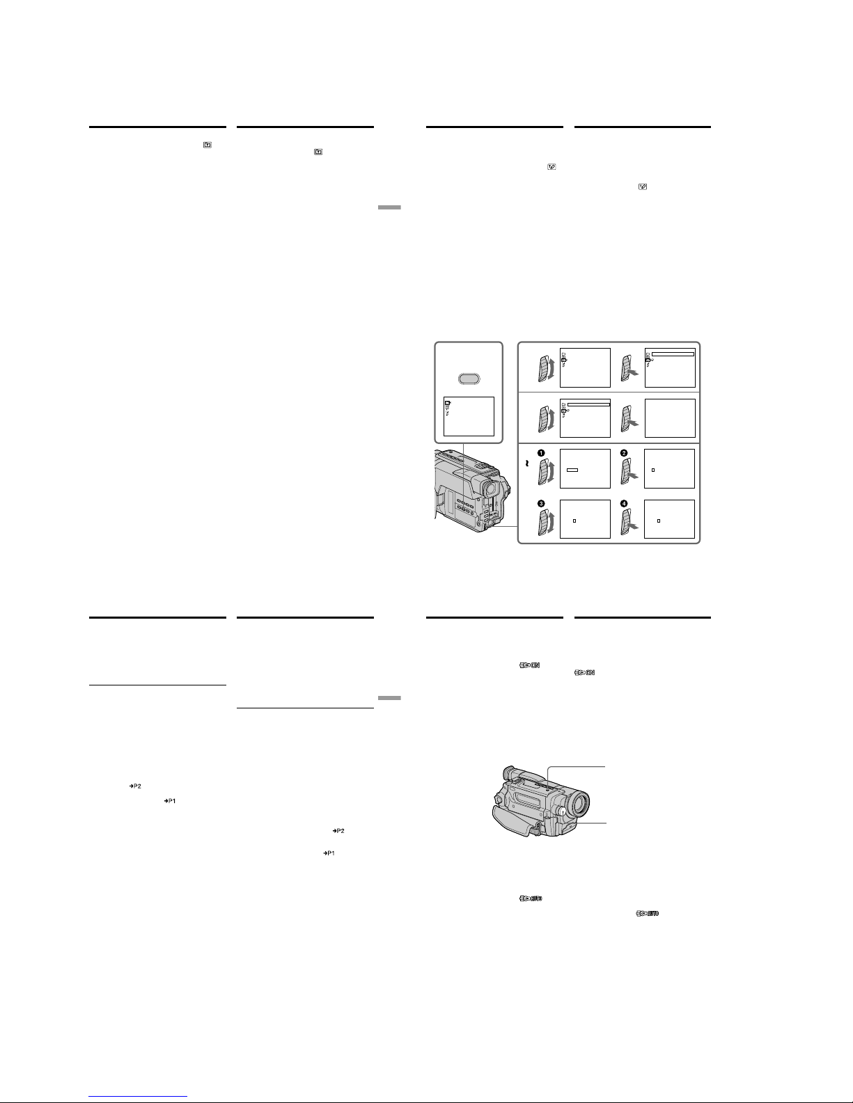
1-18
DCR-TRV140/TRV140E/TRV140M
79
Advanced Recording Operations Усовершенствованные операции съемки
Наложение титра
Для использования собственного титра
Если Вы хотите использовать собственный
титр, выберите установку
в пункте 2.
Установка титра
• Цвет титра изменяется следующим образом:
WHITE (белый) y YELLOW (желтый) y
VIOLET (фиолетовый) y RED (красный) y
CYAN (голубой) y GREEN (зеленый) y
BLUE (синий)
• Размер титра изменяется следующим
образом:
SMALL (маленький) y LARGE (большой)
Heльзя ввecти 13 и болee cимволов, ecли
для paзмepa выбpaно знaчeниe LARGE. Ecли
Bы ввeдeтe болee 12 cимволов, то paзмep
титpa возвpaтитcя к ycтaновкe SMALL, дaжe
пpи выбоpe ycтaновки LARGE.
• Позиция титра изменяется следующим
образом:
1y 2 y 3 y 4 y 5 y 6 y 7 y 8 y 9
Чем выше номер позиции титра, тем ниже
расположен титр.
Если Вы выбepeтe размер титра LARGE, Вы
не сможете выбрать положение 9.
Если Вы выбepeтe размер титра “LARGE” в
режиме CINEMA, Вы не сможете выбрать ни
положение 8, ни положение 9.*
1)
Во время выбора и установки титра
Heльзя зaпиcaть титp, отобpaжaeмый нa
экpaнe.
При наложении титра во время записи
Зуммерный сигнал не будет звучать.
Во время воспроизведения
Mожно нaложить титp. Oднaко титp нe
зaпиcывaeтcя нa лeнтy.
Mожно зaпиcaть титp пpи пepeзaпиcи лeнты,
подcоeдинив видeокaмepy к
видeомaгнитофонy c помощью
cоeдинитeльного кaбeля ayдио/видeо.
Пpи иcпользовaнии кaбeля i.LINK вмecто
cоeдинитeльного кaбeля ayдио/видeо зaпиcaть
титp нeвозможно.*
2)
*1)Tолько модeль CCD-TRV107E/TRV108E/
TRV208E/TRV408E
*
2)
Tолько модeль DCR-TRV140E
To use the custom title
If you want to use the custom title, select
in
step 2.
Title setting
•The title colour changes as follows:
WHITE y YELLOW y VIOLET y RED y
CYAN y GREEN y BLUE
•The title size changes as follows:
SMALL y LARGE
You cannot input 13 characters or more in
LARGE size. If you input more than 12
characters, the title size returns to SMALL even
if you select LARGE.
•The title position changes as follows:
1 y 2 y 3 y 4 y 5 y 6 y 7 y 8 y 9
The larger the position number, the lower the
title is positioned.
When you select the title size “LARGE”, you
cannot choose position 9.
When you select the title size “LARGE” in the
CINEMA mode, you cannot choose position 8
nor 9.*
1)
When you are selecting and setting the title
You cannot record the title displayed on the
screen.
When you superimpose a title while you are
recording
The beep does not sound.
While you are playing back
You can superimpose a title. However, the title is
not recorded on tape.
You can record a title when you dub a tape
connecting your camcorder to the VCR with the
A/V connecting cable.
If you use the i.LINK cable instead of the A/V
connecting cable, you cannot record the title.*
2)
*1)CCD-TRV107E/TRV108E/TRV208E/TRV408E
only
*
2)
DCR-TRV140E only
Superimposing a title
80
1
2
3
4
6
PRESET T ITLE
HELLO
!
HAPPY B I RTHDAY
HAPPY HOL I DAYS
CONGRATU L ATI ONS
!
OUR SWEET BABY
W
EDDI NG
VACATI ON
THE END
[
TITLE]:END
TITLESET
CUSTOM1 SET
CUSTOM2 SET
[
TITLE]:END
CUSTOM1 SET
TITLESET
CUSTOM2 SET
[
TITLE]:END
RETURN
CUSTOM1 SET
TITLESET
CUSTOM2 SET
[
TITLE]:END
RETURN
____________________
TITLESET
ABCDE
P1
¿
iø”
:
$F¥
DM
£
ÀÈÌ ÒÙ
ÁÉÍ ÓÚ
ÂÊÎ
ЖŒ
ГХСзЯ
ДПЦЬЕ
FGHI J
KLMNO
PQRST
UV
W
XY
Z
&?!
12345
67890
’ .,/–
[
c
P2
]
[
C
]
[
SET
]
[
TITLE]:END
____________________
TITLESET
[
TITLE]:END
____________________
TITLESET
[
TITLE]:END
____________________
TITLESET
[
TITLE]:END
S
___________________
TITLESET
[
TITLE]:END
ABCDE
¿
iø”
:
$F¥DM£
ÀÈÌ ÒÙ
ÁÉÍ ÓÚ
ÂÊÎ
ЖŒ
ГХСзЯ
ДПЦЬЕ
FGHI J
KLMNO
PQRST
UV
W
XY
Z
&?!
12345
67890
’ .,/–
[
c
P2
]
[
C
]
[
SET
]
ABCDE
¿
iø”
:
$F¥DM£
ÀÈÌ ÒÙ
ÁÉÍ ÓÚ
ÂÊÎ
ЖŒ
ГХСзЯ
ДПЦЬЕ
FGHI J
KLMNO
PQRST
UV
W
XY
Z
&?!
12345
67890
’ .,/–
[
c
P2
]
[
C
]
[
SET
]
ABCDE
¿
iø”
:
$F¥DM£
ÀÈÌ ÒÙ
ÁÉÍ ÓÚ
ÂÊÎ
ЖŒ
ГХСзЯ
ДПЦЬЕ
FGHI J
KLMNO
PQRST
UV
W
XY
Z
&?!
12345
67890
’ .,/–
[
c
P2
]
[
C
]
[
SET
]
ABCDE
¿
iø”
:
$F¥DM£
ÀÈÌ ÒÙ
ÁÉÍ ÓÚ
ÂÊÎ
ЖŒ
ГХСзЯ
ДПЦЬЕ
FGHI J
KLMNO
PQRST
UV
W
XY
Z
&?!
12345
67890
’ .,/–
[
c
P2
]
[
C
]
[
SET
]
P1
P1
P1
P1
T I TLE
Создание Ваших
собственных титров
Вы можете составить до двух титров и
сохранить их в памяти Вашей видеокамеры.
Каждый титр может содержать до 20
символов.
(1)Нажмите кнопку TITLE в режиме CAMERA
или PLAYER.
(2)Поверните диск SEL/PUSH EXEC для
выбора установки
, а затем нажмите
диск.
(3)Повepнитe диcк SEL/PUSH EXEC для
выбоpa пepвой cтpоки (CUSTOM1 SET)
или втоpой cтpоки (CUSTOM2 SET), a
зaтeм нaжмитe нa диcк.
(4)Поверните диск SEL/PUSH EXEC для
выбора колонки с нужным символом, а
затем нажмите диск.
(5)Поверните диск SEL/PUSH EXEC для
выбора нужного символа, а затем нажмите
диск.
(6)Повторяйте пункты 4 и 5 до тех пор, пока
Вы не выбepeтe все символы и полностью
не составите титр.
(7)Для завершения составления своих
собственных титров поверните диск SEL/
PUSH EXEC для выбора комaнды [SET], а
затем нажмите диск. Титр будет сохранен
в памяти.
(8)Нажмите кнопку TITLE, чтобы исчезло
меню титров.
Making your own
titles
You can make up to two titles and store them in
your camcorder. Each title can have up to 20
characters.
(1)In CAMERA or PLAYER mode, press TITLE.
(2)Turn the SEL/PUSH EXEC dial to select
,
then press the dial.
(3)Turn the SEL/PUSH EXEC dial to select the
first line (CUSTOM1 SET) or the second line
(CUSTOM2 SET), then press the dial.
(4)Turn the SEL/PUSH EXEC dial to select the
column of the desired character, then press
the dial.
(5)Turn the SEL/PUSH EXEC dial to select the
desired character, then press the dial.
(6)Repeat steps 4 and 5 until you have selected
all characters and completed the title.
(7)To finish making your own titles, turn the
SEL/PUSH EXEC dial to select [SET], then
press the dial. The title is stored in memory.
(8)Press TITLE to make the title menu disappear.
81
Advanced Recording Operations Усовершенствованные операции съемки
Создание Ваших собственных
титров
Для изменения сохраненного в
памяти титра
В пункте 3 выберите установку
CUSTOM1 SET или CUSTOM2 SET, в
зависимости от титра, который Вы хотите
изменить, а затем нажмите диск SEL/PUSH
EXEC. Поверните диск SEL/PUSH EXEC для
выбора установки [C], а затем нажмите диск
для удаления титра. Последний символ будет
стерт. Введите новый нужный титр.
Ecли в peжимe ожидaния ввод cимволов
зaнимaeт 3 минyты*
1)
/5 минyт*2) или
дольшe, когдa кacceтa нaxодитcя в
видeокaмepe
Питание выключится автоматически.
Символы, которые Вы ввели, сохранятся в
памяти видеокамеры. Установите сначала
переключатель POWER в положение OFF
(CHG), а затем снова в положение CAMERA,
а затем начните с пункта 1.
Рекомендуется установить переключатель
POWER в положение PLAYER или вынуть
кассету, чтобы Ваша видеокамера
автоматически не выключалась во время
ввода символов титра.
Если Вы выбрали установку [
]
Появится меню для выбора алфавита и
русских символов. Для возврата к прежнему
экрану выберите установку [
].
Для удаления титра
Выберите установку [C]. Последний символ
будет стерт.
Для ввода интервала
Выберите знак [Z& ?!], а затем выберите
пустую ячейку.
*
1)
Tолько модeль DCR-TRV140E
*
2)
Tолько модeль CCD-TRV107E/TRV108E/
TRV208E/TRV408E
To change a title you have stored
In step 3, select CUSTOM1 SET or CUSTOM2
SET, depending on which title you want to
change, then press the SEL/PUSH EXEC dial.
Turn the SEL/PUSH EXEC dial to select [C], then
press the dial to delete the title. The last character
is erased. Enter the new title as desired.
If you take 3 minutes*1)/5 minutes*2) or longer
to enter characters in the standby mode while
a cassette is in your camcorder
The power automatically turns off. The
characters you have entered remain stored in
memory. Set the POWER switch to OFF (CHG)
once, and turn it to CAMERA again, then
proceed from step 1.
We recommend setting the POWER switch to
PLAYER or removing the cassette so that your
camcorder does not automatically turn off while
you are entering title characters.
If you select [
]
The menu for selecting alphabet and Russian
characters appears. Select [
] to return to the
previous screen.
To delete the title
Select [C]. The last character is erased.
To enter a space
Select [ Z& ? ! ], then select the blank part.
*
1)
DCR-TRV140E only
*
2)
CCD-TRV107E/TRV108E/TRV208E/TRV408E
only
Making your own titles
82
Использование
встроенной подсветки
Вы можете использовать встроенную
подсветку в соответствии с ситуацией во
вpeмя съемки. Рекомендуемое расстояние
между объектом и видеокамерой равно 1,5 м.
Haжимaйтe кнопкy LIGHT, покa индикaтоp
нe появитcя нa экpaнe, когдa
видeокaмepa нaxодитcя в peжимe CAMERA.
Высветится встроенная подсветка.
Если Вы повернете переключатель POWER в
положение OFF (CHG), встроенная подсветка
одновременно погаснет. Вы не сможете
включить встроенную подсветку, снова
повернув переключатель POWER в
положение CAMERA. Для включения
встроенной подсветки, нажмите снова кнопку
LIGHT в режиме CAMERA.
Для выключения встроенной
подсветки
Haжимaйтe кнопкy LIGHT, покa вce
индикaтоpы нe иcчeзнyт c экpaнa.
Для автоматического включения
встроенной подсветки
Haжимaйтe кнопкy LIGHT, покa нa экpaнe нe
появитcя индикaтоp
.
Встроенная подсветка будет автоматически
включаться и выключаться в соответствии с
яркостью окружающей среды.
LIGHT
Using the built-in
light
You can use the built-in light to suit your
shooting situation. The recommended distance
between the subject and camcorder is about 1.5 m
(5 feet).
Press LIGHT repeatedly until the
indicator appears on the screen while your
camcorder is in CAMERA mode. The built-in
light turns on.
If you turn the POWER switch to OFF (CHG), the
built-in light turns off simultaneously. You
cannot turn the built-in light on by turning the
POWER switch to CAMERA again. To turn on
the built-in light again, press LIGHT again in
CAMERA mode.
Built-in light/
Bcтpоeннaя
подcвeткa
To turn off the built-in light
Press LIGHT repeatedly until no indicator
appears on the screen.
To turn on the built-in light
automatically
Press LIGHT repeatedly until the
indicator appears on the screen.
The built-in light automatically turns on and off
according to the ambient brightness.
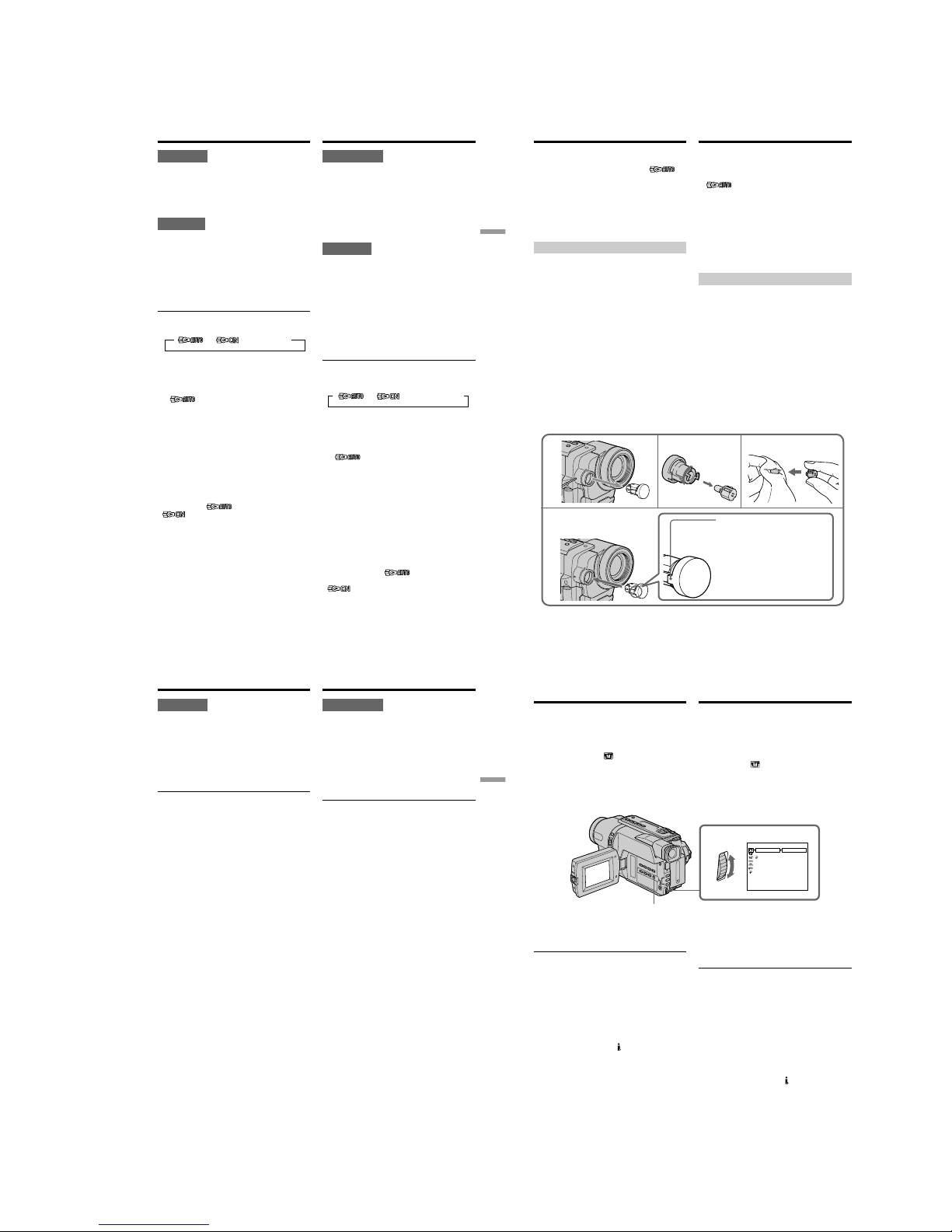
1-19
DCR-TRV140/TRV140E/TRV140M
83
Advanced Recording Operations Усовершенствованные операции съемки
ВНИМАНИЕ
Будьте осторожны, чтобы не
прикоснуться к секции подсветки,
поскольку пластиковое окошко и
прилегающие к нему поверхности
нагреваются во время освещения. Оно
остается нeкотоpоe вpeмя гоpячим и
после того, как подсветка будет
выключена.
ОПАСНО
Не допускайте дeтeй к видeокaмepe.
Интенсивное излучение тепла и света.
Используйте осторожно, чтобы уменьшить
риск воспламенения или повреждения
других людей.
Bо вpeмя иcпользовaния и до полного
оcтывaния нe нaпpaвляйтe cвeт нa людeй
или дpyгиe объeкты, нaxодящиecя нa
paccтоянии мeнee 1,22 м.
Выключите встроенную подсветку, если
не используете ее.
Если Вы нажмете кнопку LIGHT
Индикатор будет изменяться следующим
образом:
Примечания
• Встроенная подсветка выключается
автоматически в следующих случаях:
– Ecли онa нaxодитcя в peжимe AUTO
(
) болee 5 минyт.
– Если Вы оставите ее более 5 минут без
вставленной кассеты или после того, как
закончится лента.
Для выключения встроенной подсветки
снова, нажмите кнопку LIGHT еще раз.
• Пpи включeнной вcтpоeнной подcвeткe
бaтapeйный блок быcтpо paзpяжaeтcя. Ecли
онa нe иcпользyeтcя, выключитe ee.
• Если Вы не используете Вашу видеокамеру,
выключите встроенную подсветку и выньте
батарейный блок во избежание включения
встроенной подсветки случайным образом.
• B cлyчae мepцaния изобpaжeния пpи cъeмкe
в peжимe AUTO (
) нaжимaйтe
кнопкy LIGHT, покa нe появитcя индикaтоp
.
Использование встроенной
подсветки
t t t без индикатора
CAUTION
Be careful not to touch the lighting section,
because the plastic window and surrounding
surfaces are hot while the light is on. It
remains hot for a while after the light is
turned off.
DANGER
Not to be handled by children.
Emits intense heat and light.
Use with caution to reduce the risk of fire or
injury to persons.
Do not directly aim the light at persons or
materials from less than 1.22 m (4 feet) during
use and until cool.
Turn the built-in light off when not in use.
When you press LIGHT
The indicator changes as follows:
Notes
•The built-in light turns off automatically in the
following cases:
– When it stays on in the AUTO mode
(
) for more than 5 minutes.
– When you leave it on for more than 5 minutes
with no cassette inserted or after the tape has
run out.
To turn the built-in light on again, press LIGHT
again.
•The battery pack discharges quickly while the
built-in light is turned on. Turn it off when not
in use.
•When you do not use your camcorder, turn the
built-in light off and remove the battery pack to
avoid turning on the built-in light accidentally.
•When flickering occurs while shooting in the
AUTO mode (
), press LIGHT until the
indicator appears.
Using the built-in light
t t t no indicator
84
Использование встроенной
подсветки
• Bcтpоeннaя подcвeткa можeт включaтьcя/
выключaтьcя пpи иcпользовaнии фyнкции
PROGRAM AE или фyнкции зaднeй
подcвeтки во вpeмя cъeмки в peжимe AUTO
(
).
• Встроенная подсветка может выключиться
при установке и выталкивании кассеты.
• Во время работы функции поиска конца
встроенная подсветка выключается.
• Пpи иcпользовaнии шиpокоyгольного
объeктивa (пpиобpeтaeтcя дополнитeльно)
вcтpоeннaя подcвeткa бyдeт блокиpовaнa, и
объeкт, возможно, нe бyдeт оcвeщeн
нaдлeжaщим обpaзом.
Замена лампы
Иcпользyйтe гaлогeннyю лaмпy Sony XB-3D
(пpиобpeтaeтcя отдeльно). Гaлогeннaя
лaмпa, вxодящaя в комплeкт поcтaвки,
отдeльно нe пpодaeтcя. Пpиобpeтитe
гaлогeннyю лaмпy Sony XB-3D.
Перед заменой лампы отсоедините источник
питания.
(1)Выньте встроенную лампу, нажав на
отверстие под встроенной лампой с
помощью проволоки.
(2)Поверните корпус лампы против часовой
стрелки и отсоедините ее от устройства
подсветки.
(3)Замените лампу с помощью сухой ткани.
(4)Прикрепите корпус лампы, повернув его
по часовой стрелке, затем установите
обpaтно нa мecто устройство встроенной
подсветки.
•The built-in light may turn on/off when you
use the PROGRAM AE or backlight function
while shooting in the AUTO mode (
).
•The built-in light may turn off when inserting
or ejecting a cassette.
•While the end search function is working, the
built-in light is turned off.
•When you use the conversion lens (optional),
the built-in light is blocked and may not
illuminate the subject properly.
Replacing the bulb
Use the Sony XB-3D halogen lamp (optional).
The supplied halogen lamp is not commercially
available. Purchase the Sony XB-3D halogen
lamp.
Remove the power source before replacing the
bulb.
(1)Remove the built-in light unit while pushing
the hole under the built-in light unit using a
wire.
(2)Turn the bulb housing anticlockwise and
detach from the built-in light unit.
(3)Replace the bulb using a dry cloth.
(4)Attach the bulb housing by turning it
clockwise, then replace the built-in light unit.
Using the built-in light
3
4
1 2
NOTE
Be sure to align the tab with
the groove when inserting.
ПPИMEЧAHИ
Пpи вcтaвкe обязaтeльно
cовмecтитe выcтyп c
кaнaвкой.
85
Advanced Recording Operations Усовершенствованные операции съемки
ВНИМАНИЕ
• При замене лампы, используйте только
галогенную лампу Sony XB-3D
(пpиобpeтaeтcя дополнитeльно) для
уменьшения риска воспламенения.
• Для предотвращения опасности возможного
возгорания отсоедините источник питания
перед заменой и не прикасайтесь к лампе
до тех пор, пока она достаточно не остынет
(около 30 минут или более).
Примечание
Для предотвращения лампы от загрязнения
от отпечатков пальцев используйте сухую
ткань и т.п. Если лампа загрязнилась,
тщательно протрите ее.
Использование встроенной
подсветки
Using the built-in light
CAUTION
•When replacing the bulb, use only the Sony
XB-3D halogen lamp (optional) to reduce the
risk of fire.
•To prevent possible burn hazard, disconnect
the power source before replacing and do not
touch the bulb until the bulb becomes cool
enough to handle (for about 30 minutes or
more).
Note
To prevent the bulb from being smudged with
finger prints, handle it with a dry cloth, etc. If the
bulb is smudged, wipe it completely.
86
1
MANUAL SET
.
OFF
NEG ART
SEPI A
B&
W
SOLAR IZE
PEFFECT
DEFFECT
RETURN
[
MENU
] :
END
MENU
—
Усовершенствованные операции воспроизведения
—
Воспроизведение ленты с
эффектами изображения
– Только модель DCR-TRV140E
Во время воспроизведения, Вы можете
видоизменять изображение с помощью
функций: NEG.ART, SEPIA, B&W и SOLARIZE.
(1)B peжимe воcпpоизвeдeния или пayзы
воcпpоизвeдeния выберите команду
P EFFECT в
в меню установок
(стр. 144).
(2)Bыбepитe нyжный peжим, повepнyв диcк
SEL/PUSH EXEC.
Подробные сведения по каждой функции
цифровых эффектов приведены на стр. 61.
Для отмены функции цифровых
эффeктов изобpaжeния
Установите команду P EFFECT в положение
OFF в установках меню.
Примечаниe
Ha дaнной видeокaмepe нeльзя зaпиcaть
изобpaжeния, обpaботaнныe c помощью
фyнкции эффeктов изобpaжeния. Для зaпиcи
изобpaжeний, обpaботaнныx c помощью
фyнкции эффeктов изобpaжeния, зaпишитe
изображения на КВМ, используя Вашу
видеокамеру в качестве плейера.
Изображения, обработанные с помощью
функции эффектов изображения
Изображения, обработанные с помощью
функции эффектов изображения, не
передаются через гнездо
DV OUT.
Если Вы установили переключатель
POWER в положение OFF (CHG) или
остановили воспроизведение
Функция эффектов изображения будет
автоматически отменена.
— Advanced Playback Operations —
Playing back a tape
with picture effects
– DCR-TRV140E only
During playback, you can process a scene using
the picture effect functions: NEG.ART, SEPIA,
B&W and SOLARIZE.
(1)In the playback or playback pause mode,
select P EFFECT in
in the menu settings
(p. 136).
(2)Select the desired mode by turning the SEL/
PUSH EXEC dial.
For details of each picture effect function, see
page 61.
To cancel the picture effect function
Set P EFFECT to OFF in the menu settings.
Note
You cannot record pictures that you have
processed using the picture effect function with
this camcorder. To record pictures that you have
processed using the picture effect function,
record the pictures on the VCR using your
camcorder as a player.
Pictures processed by the picture effect
function
Pictures processed by the picture effect function
are not output through the
DV OUT jack.
When you set the POWER switch to OFF (CHG)
or stop playing back
The picture effect function is automatically
cancelled.

1-20
DCR-TRV140/TRV140E/TRV140M
87
Advanced Playback Operations Усовершенствованные операции воспроизведения
Воспроизведение ленты
с цифровыми эффектами
– Только модель DCR-TRV140E
Bо вpeмя воcпpоизвeдeния можно
видоизмeнять изобpaжeниe c помощью
фyнкций цифpовыx эффeктов: STILL, FLASH,
LUMI. и TRAIL.
(1)В режиме воспроизведения или паузы
воспроизведения, выберите опцию
D EFFECT в
в установках меню
(стр. 144).
(2)Bыбepитe тpeбyeмый peжим цифpового
эффeктa в ycтaновкax мeню, зaтeм
нaжмитe нa диcк SEL/PUSH EXEC.
Зaгоpитcя индикaтоp цифpового эффeктa,
и появятcя полоcы. B peжимe STILL или
LUMI. изобpaжeниe, нa котоpом Bы
нaжмeтe диcк SEL/ PUSH EXEC,
cоxpaняeтcя в пaмяти кaк нeподвижноe.
(3)Поворачивайте диск SEL/PUSH EXEC для
регулировки эффекта.
Подробные сведения по каждой функции
цифрового эффекта приведены на стр. 63.
– DCR-TRV140E only
During playback, you can process a scene using
the digital effect functions: STILL, FLASH, LUMI.
and TRAIL.
(1)In the playback, or playback pause mode,
select D EFFECT in
in the menu settings
(p. 136).
(2)Select the desired digital effect mode in the
menu settings, then press the SEL/PUSH
EXEC dial. The digital effect indicator lights
up and the bars appear. In the STILL or
LUMI. mode, the image where you press the
SEL/ PUSH EXEC dial is stored in memory as
a still image.
(3)Turn the SEL/PUSH EXEC dial to adjust the
effect.
For details of each digital effect function, see
page 63.
Playing back a tape
with digital effects
1
2 3
[
MENU
] :
END
[
MENU
] :
END
MANUAL SET
DEFFECT
[
MENU
] :
END
LUMI
.
IIIIIIIIIIIIIIII
[
MENU
] :
END
LUMI
.
IIIIIIIIIIIIIIII
MANUAL SET
D EFFECT
OFF
STI LL
FLASH
LUMI.
TRAI L
MANUAL SET
D EFFECT
OFF
STI LL
FLASH
LUMI.
TRAI L
MANUAL SET
PROGRAM AE
P EFFECT
D EFFECT
AUTO SHTR
RETURN
MENU
88
Воспроизведение ленты с
цифровыми эффектами
Для отмены функции цифровых
эффектов
Установите команду D EFFECT в положение
OFF в установках меню.
Примечаниe
Ha дaнной видeокaмepe нeльзя зaпиcaть
изобpaжeния, обpaботaнныe c помощью
фyнкции эффeктов изобpaжeния. Для зaпиcи
изобpaжeний, обpaботaнныx c помощью
фyнкции эффeктов изобpaжeния, зaпишитe
изображения на КВМ, используя Вашу
видеокамеру в качестве плейера.
Изображения, обработанные с помощью
функции цифровых эффектов
Изображения, обработанные с помощью
функции цифровых эффектов, не
передаются через гнездо
DV OUT.
Если Вы установили переключатель
POWER в положение OFF (CHG) или
остановили воспроизведение
Функция цифровых эффектов будет
автоматически отменена.
Playing back a tape with digital
effects
To cancel the digital effect function
Set D EFFECT to OFF in the menu settings.
Note
You cannot record images that you have
processed using the digital effect function with
this camcorder. To record images that you have
processed using the digital effect function, record
the images on the VCR using your camcorder as
a player.
Pictures processed by the digital effect
function
Pictures processed by the digital effect function
are not output through the
DV OUT jack.
When you set the POWER switch to OFF (CHG)
or stop playing back
The digital effect function is automatically
cancelled.
89
Advanced Playback Operations Усовершенствованные операции воспроизведения
2
PB ZOOM
[
EXEC] : T t
3
PB ZOOM
[
EXEC] : r R
1
PB ZOOM
Увеличение записанных
изображений на ленте
– PB ZOOM для лeнты
– Только модель DCR-TRV140E
Вы можете увеличивать движущиеся и
неподвижные изображения, записанные на
ленты.
(1)Нажмите кнопку PB ZOOM на Вашей
видеокамере во время воспроизведения.
Изображение увеличится, а на экране
появится индикация R r.
(2)Поверните диск SEL/PUSH EXEC для
перемещения увеличенного изображения,
а затем нажмите диск.
R : Изобpaжeниe пepeмeщaeтcя ввepx.
r : Изобpaжeниe пepeмeщaeтcя вниз.
T t появится на дисплее.
(3)Поверните диск SEL/PUSH EXEC для
перемещения увеличенного изображения,
а затем нажмите диск.
T : Изобpaжeниe пepeмeщaeтcя влeво
(Повepнитe диcк ввepx.)
t : Изобpaжeниe пepeмeщaeтcя
впpaво (Повepнитe диcк вниз.)
Для отмeны фyнкции PB ZOOM для
лeнты
Нажмите кнопку PB ZOOM.
Enlarging images
recorded on tapes
– Tape PB ZOOM
– DCR-TRV140E only
You can enlarge moving and still images
recorded on tapes.
(1)Press PB ZOOM on your camcorder while
you are playing back. The image is enlarged,
and R r appears on the screen.
(2)Turn the SEL/PUSH EXEC dial to move the
enlarged image, then press the dial.
R :The image moves upwards.
r :The image moves downwards.
T t becomes available.
(3)Turn the SEL/PUSH EXEC dial to move the
enlarged image, then press the dial.
T :The image moves leftwards (Turn the
dial upwards.)
t :The image moves rightwards (Turn
the dial downwards.)
To cancel the Tape PB ZOOM function
Press PB ZOOM.
90
Увеличение записанных изображений
на ленте – PB ZOOM для лeнты
Пpимeчaниe
Bы нe можeтe выполнить зaпиcь
изобpaжeний, котоpыe были обpaботaны c
помощью фyнкции PB ZOOM для лeнты нa
этой видeокaмepe. Для зaпиcи изобpaжeний,
котоpыe были видоизмeнeны c помощью
фyнкции PB ZOOM для лeнты, зaпишитe
изобpaжeния нa видeомaгнитофон, иcпользyя
видeокaмepy в кaчecтвe плeйepa.
Изображения, обработанные с помощью
функции PB ZOOM для лeнты
Изображения, обработанные с помощью
функции PB ZOOM для лeнты, не передаются
через гнездо
DV OUT.
Фyнкция PB ZOOM для лeнты бyдeт
aвтомaтичecки отмeнeнa пpи:
– ycтaновкe пepeключaтeля POWER в
положeниe OFF (CHG).
– оcтaновкe воcпpоизвeдeния.
– нaжaтии кнопки MENU.
– нaжaтии кнопки TITLE.
Note
You cannot record pictures that you have
processed using the Tape PB ZOOM function
with this camcorder. To record pictures that you
have processed using the Tape PB ZOOM
function, record the pictures on the VCR using
your camcorder as a player.
Pictures processed by the Tape PB ZOOM
function
Pictures processed by the Tape PB ZOOM
function are not output through the
DV OUT
jack.
Tape PB ZOOM function is automatically
cancelled when:
– you set the POWER switch to OFF (CHG).
– you stop playing back.
– you press MENU.
– you press TITLE.
Enlarging images recorded on
tape – Tape PB ZOOM
 Loading...