

Sony TCTX-313 Service manual
TC-TX313/TX515
SERVICE MANUAL
• TC-TX313 is the optional stereo cassette
deck that can be used only with section
DHC-MD313.
• TC-TX515 is the optional stereo cassette
deck that can be used only with section
DHC-MD515.
SPECIFICATIONS
Recording system 4-track 2-channel stereo
Frequency response (DOLBY NR OFF)
50 - 14,000 Hz (± 3 dB),
using Sony TYPE I
cassettes
50 - 15,000 Hz (± 3 dB),
using Sony TYPE II
cassettes
Input TAPE IN (phono jacks):
impedance 47 kilohms
Output TAPE OUT (phono jacks):
voltage 550 mV
impedance 47 kilohms
Photo: TC-TX515
US Model
Tourist Model
TC-TX515
AEP Model
UK Model
E Model
TC-TX313/TX515
Model Name Using Similar Mechanism NEW
Tape Transport Mechanism Type
General
Power requirements
US model: 120 V AC, 60 Hz
AEP, UK model: 220 - 230 V AC, 50 / 60 Hz
E, Tourist model: 110 - 120 V or 220 - 240 V
AC, 50 / 60 Hz
Adjustable with the
voltage selector
Power consumption 12 W
Dimensions Approx. 215 × 60 × 195
mm (w / h / d)
incl. projecting parts and
controls
Mass Approx. 2.5 kg
Supplied accessories: Audio connecting cords
(2)
Design and specifications are subject to change
without notice.
SAFETY-RELATED COMPONENT WARNING!!
COMPONENTS IDENTIFIED BY MARK ! OR DOTTED LINE
WITH MARK ! ON THE SCHEMATIC DIAGRAMS AND IN
THE PARTS LIST ARE CRITICAL TO SAFE OPERATION.
REPLACE THESE COMPONENTS WITH SONY PARTS WHOSE
P ART NUMBERS APPEAR AS SHOWN IN THIS MANUAL OR
IN SUPPLEMENTS PUBLISHED BY SONY.
Dolby noise reduction manufactured under license from Dolby Laboratories Licensing Corporation.
“DOLBY” and the double-D symbol a are trademarks of Dolby
Laboratories Licensing Corporation.
Notes on Chip Component Replacement
• Never reuse a disconnected chip component.
• Notice that the minus side of a tantalum capacitor may be dam-
aged by heat.
STEREO CASSETTE DECK
MICROFILM
– 1 –

TABLE OF CONTENTS
1. GENERAL
Parts and Controls...................................................................... 3
2. TEST MODE
2-1. Checking the Items of Test Mode ......................................... 4
3. DISASSEMBLY
3-1. Top Cover.............................................................................. 5
3-2. Front Panel Assy ................................................................... 5
3-3. Front Board (TC-TX313) ...................................................... 6
3-4. Panel Board (TC-TX515)...................................................... 6
3-5. Back Plate ............................................................................. 7
3-6. Bracket (Power Trans) .......................................................... 7
3-7. Main Board ........................................................................... 8
3-8. TCM Assy ............................................................................. 8
3-9. Lever ..................................................................................... 9
3-10. T ension Spring....................................................................... 9
3-11. Housing ............................................................................... 10
3-12. Chassis ................................................................................ 10
3-13. Motor (A)/(B) Assy..............................................................11
3-14. Head Plate ............................................................................11
3-15. Pinch Roller Assy................................................................ 12
3-16. Bracket (Head Unit) ............................................................ 12
4. MECHANICAL ADJUSTMENTS................................. 13
5. ELECTRICAL ADJUSTMENTS................................... 13
6. DIAGRAMS
6-1. Circuit Boards Location ...................................................... 16
6-2. Printed Wiring Board –Deck Section– ................................ 17
6-3. Schematic Diagram –Deck Section–................................... 18
6-4. Printed Wiring Boards –Main Section– .............................. 20
6-5. Schematic Diagram –Main Section–................................... 23
6-6. Printed Wiring Boards –Front Panel Section– .................... 27
6-7. Schematic Diagram –Front Panel Section–......................... 29
6-8. IC Pin Description............................................................... 31
7. EXPLODED VIEWS
7-1. Top Cover Section............................................................... 33
7-2. Front Panel Section (TC-TX313)........................................ 34
7-3. Front Panel Section (TC-TX515)........................................ 35
7-4. Chassis Section ................................................................... 36
7-5. TCM Assy Section .............................................................. 37
8. ELECTRICAL PARTS LIST........................................... 38
– 2 –
SECTION 1
GENERAL
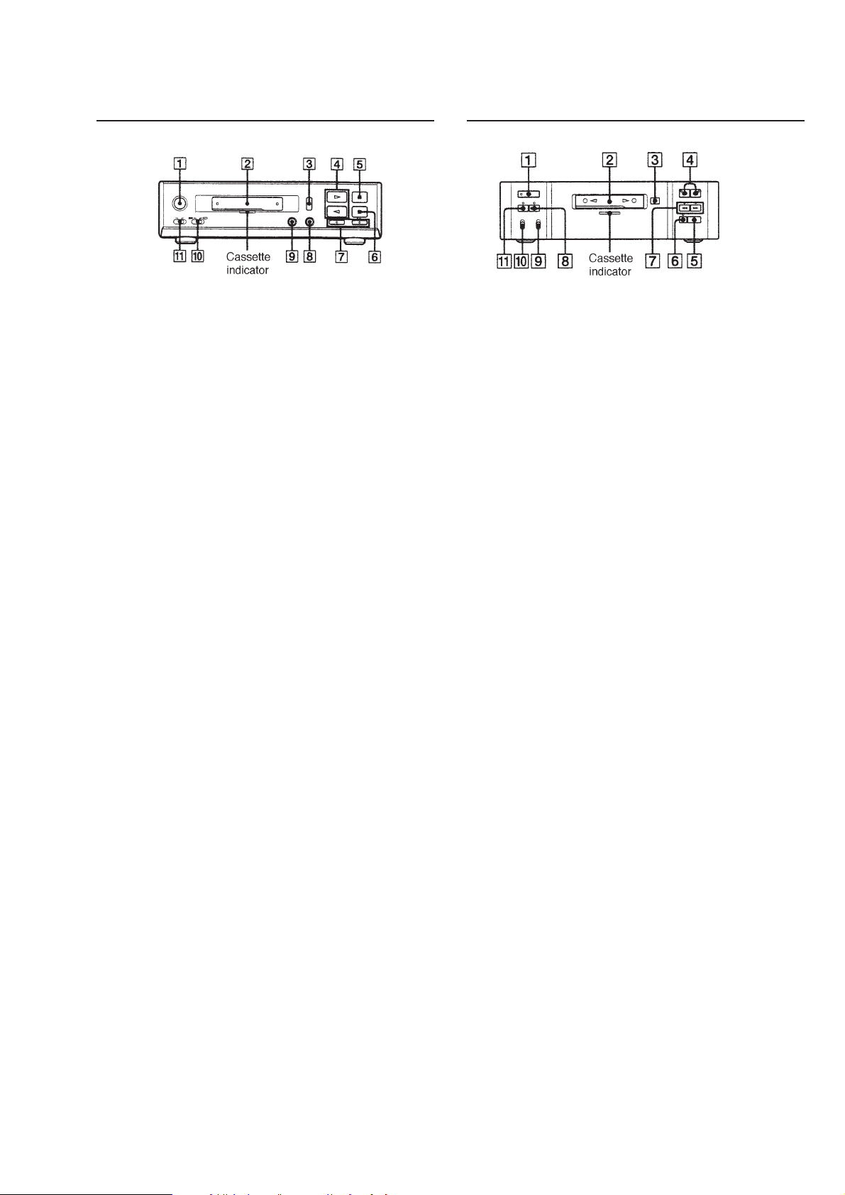
• TC-TX313
Parts and Controls
1 POWER switch
Only the power to this set is turn on.
2 Cassette slot
With a cassette inserted, the cassette
indicator is illuminated red when the
power is turned on.
3 § (eject) button
4 ª (lower side play)/
· (upper side play) button
Even without cassette, the power to
this set and the DHC-MD313 will be turned
on when one of these buttons is pressed.
5 ∏ (pause) button
6 π (stop) button
7 º/‚ (fast forward, fast backward/AMS)
button
8 ® REC (recording) button
9 CD SYNC (CD synchro) button
This button allows CD synchro recording
to be executed as this set is interlocked
with the DHC-MD313.
!º DIRECTION switch
!¡ DOLBY NR (Dolby Noise Reduction) switch
• TC-TX515
Parts and Controls
1 POWER switch
Only the power to this set is turn on.
2 Cassette slot
With a cassette inserted, the cassette
indicator is illuminated red when the
power is turned on.
3 6 (eject) button
4 9 (lower side play)/
( (upper side play) button
5 p (stop) button
6 P (pause) button
7 0/) (fast forward, fast backward/AMS)
button
8 r REC (recording) button
9 DIRECTION switch
!º DOLBY NR (Dolby Noise Reduction) switch
!¡ CD SYNC (CD synchro) button
This button allows CD synchro recording
to be executed as this set is interlocked
with the DHC-MD515.
– 3 –

SECTION 2
TEST MODE
2-1. CHECKING THE ITEMS OF TEST MODE
The set allows you to check the items of the test mode although this
may not be directly related with the adjustment.
3) All LED Flickering
When no tape is inserted, all LED indicators are flickering.
1 Setting/Releasing the Test Mode:
1) Setting
With power OFF, short between test pin 1 and pin 2 of
CN09 on the LOW-VOLTAGE board. (See page 15.)
Then, turn power ON to enter the test mode.
2) Releasing
Open between pin 1 and pin 2 of CN09.
2 Items of Test Mode
1) Memory Stop
1-1) In side A record mode, press the REW ( 0 ) button.
The tape is rewind to the start point of recording and stopped.
1-2) In side B record mode, press the FF ( ) ) button.
The tape is rewind to the start point of recording and stopped.
2) Memory Play
2-1) In side A record mode, press the FWD Auto Play
( ” + 0 ) buttons simultaneously. The tape is rewind to
the start point of recording and FWD played.
2-2) In side B record mode, press the REV Auto Play
( “ + ) ) buttons simultaneously. The tape is rewind to
the start point of recording and REV played.
4) Aging Operation
When tape with record erase preventing claw is inserted for
both sides A and B, enter the aging operation start command
by pressing p and CD SYNC simultaneously. The system
will change the direction to one side and perform the
following operations:
1 Rewind in REW mode until side A of tape is stopped.
2 Playback tape in FWD mode for 1 minute.
3 Pause mode.
4 Record tape for 3 minutes.
5 Forward tape in FF mode to the end of side A of tape.
6 Shut off and switch to side B.
7 Playback tape in REV mode for 1 minute.
8 Pause mode.
9 Record tape for 3 minutes.
!º Forward tape in FF mode to the end of side B of tape.
!¡ Shut off and switch to side A.
!™ Repeat the procedure from 2 to !¡.
!£ Pressing the STOP ( p ) button will release the set from
these operations.
– 4 –
SECTION 3
DISASSEMBLY
Note : Follow the disassembly procedure in the numerical order given.
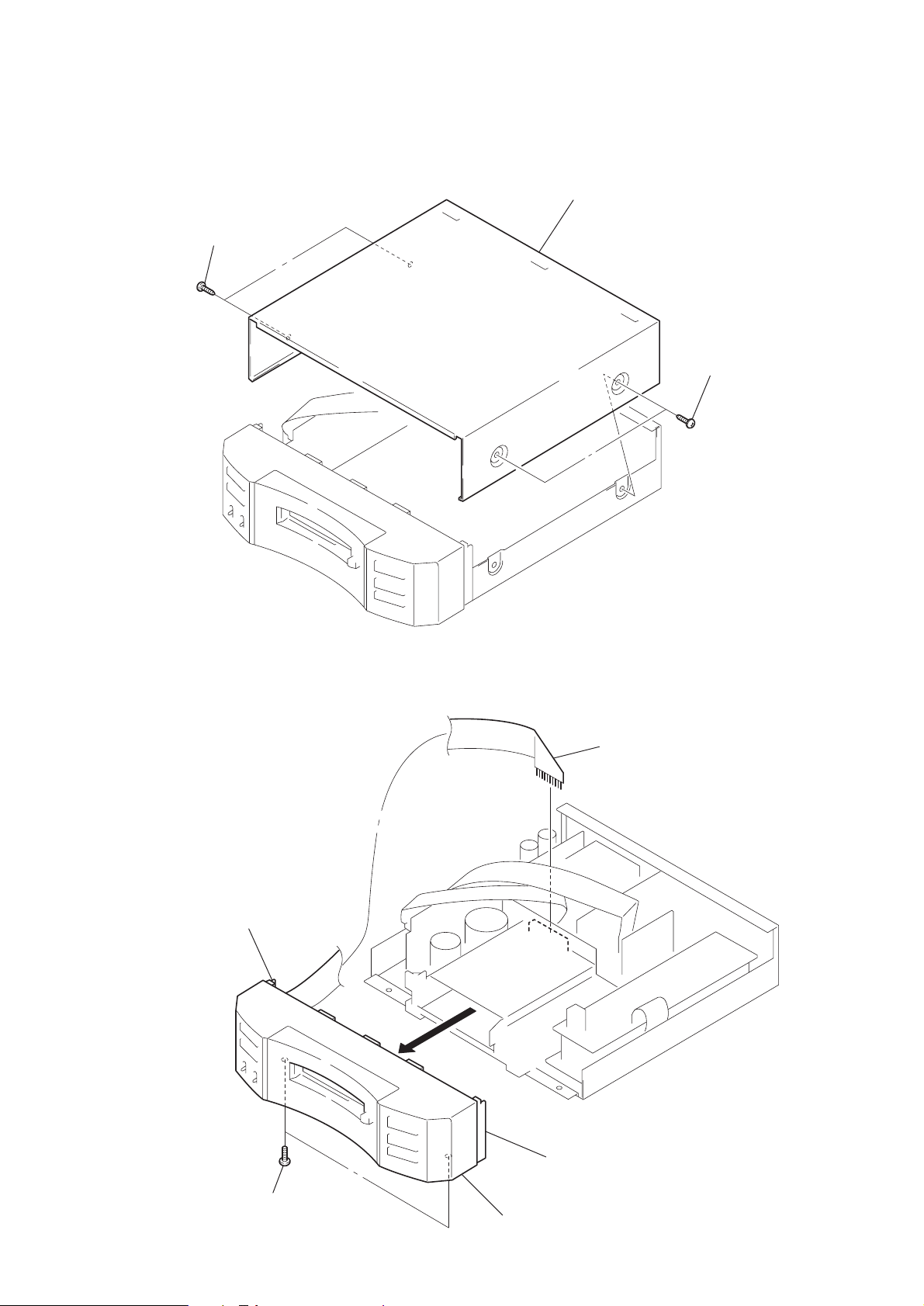
3-1. T OP COVER
1
screws (case 3 TP2)
3
top cover
2
screws (case 3 TP2)
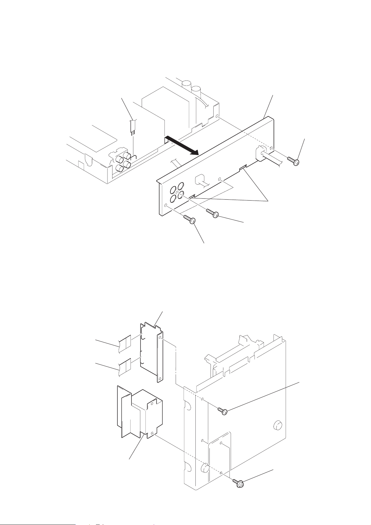
3-2. FRONT PANEL ASSY
3
claw
1
CN6
2
BVTT 3x8
5
front panel assy
– 5 –
4
claw
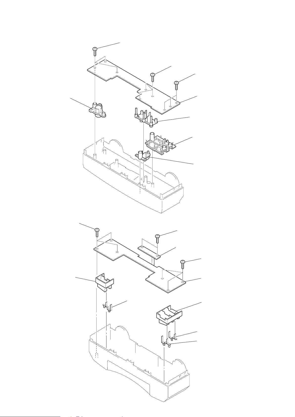
3-3. FRONT BOARD (TC-TX313)
d
d
8
POWER button
1
BVTP 2.6x8
2
BVTP 2.6x8
3
BVTP 2.6x8
4
FRONT boar
6
REC button
5
PLAY button
7
EJECT button
3-4. PANEL BOARD (TC-TX515)
4
BVTP 2.6x8
6
POWER button
7
lens (C)
1
2
BVTP 2.6x8
LED board
9
!º
3
BVTP 2.6x8
5
PANEL boar
8
PLAY button
lens (D)
lens (C)
– 6 –
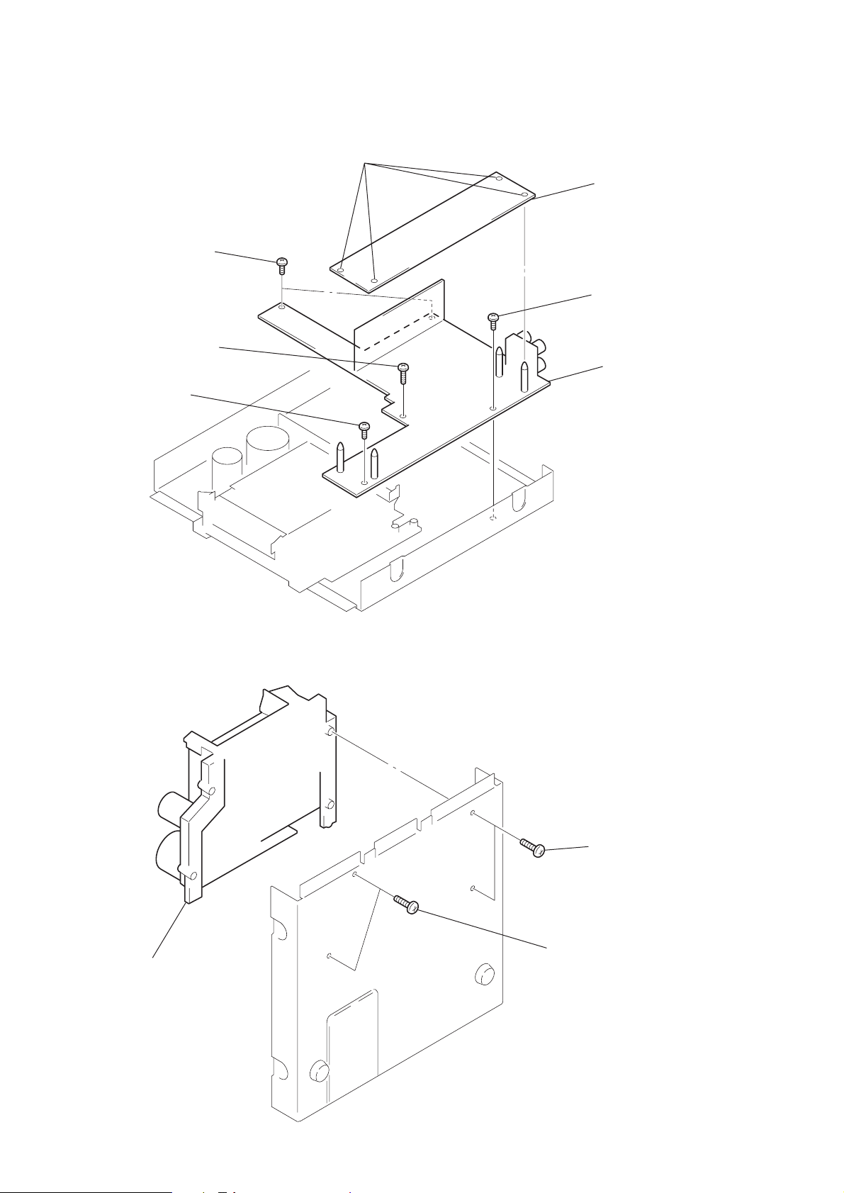
3-5. BACK PLATE
8
1
CN04
2
BVTP 3x10
6
back plate
5
claws
4
BVTP 3x
3-6. BRACKET (POWER TRANS)
2
CN14
1
CN7
4
DECK board
3
BVTP 3x8
3
BVTP 3x8
6
bracket (power trans)
– 7 –
5
bind type (A)
3-7. MAIN BOARD
d
0
5
3
4
BVTP 3x8
BVTP 3x8
BVTP 3x10
1
PC board holders
2
REC board
6
BVTP 3x8
7
MAIN boar
3-8. TCM ASSY
3
TCM assy
2
BVTP 3x1
1
BVTP 3x10
– 8 –
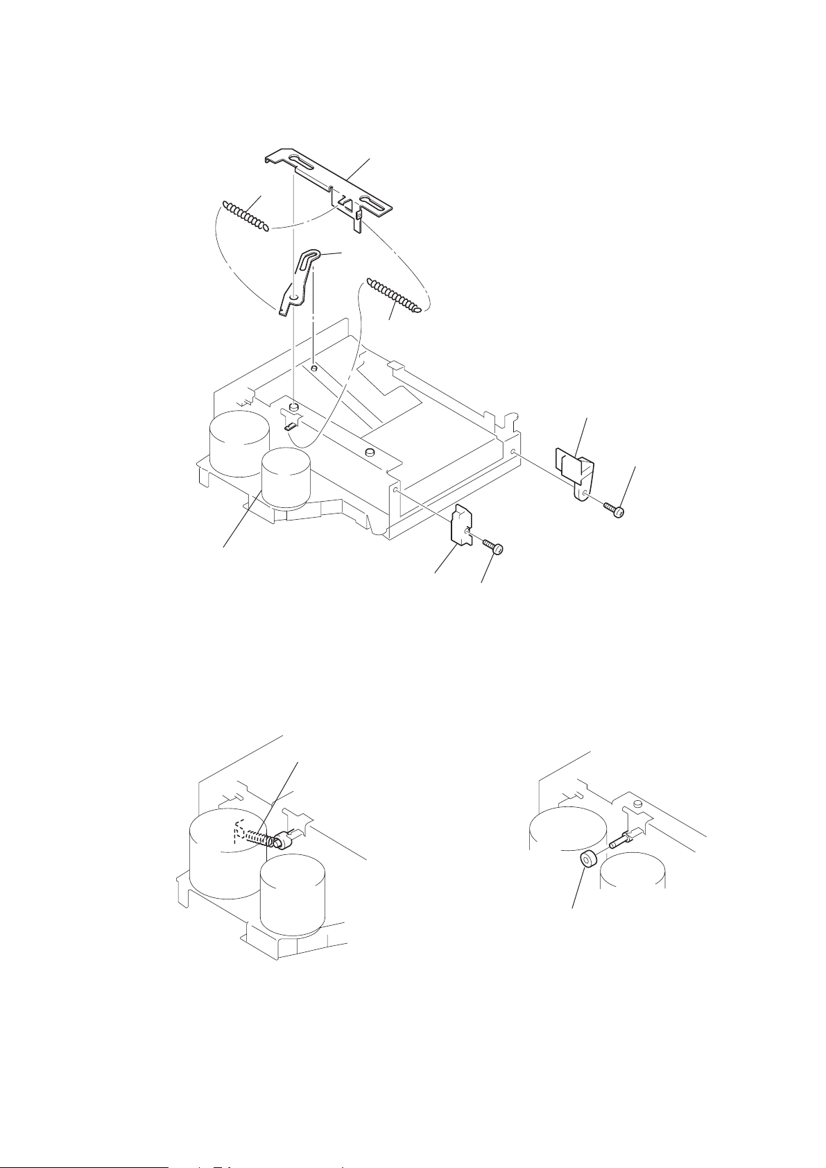
3-9. LEVER
8
7
9
8
5
4
tape guide (R)
3
BVTP 3x
6
Turn the loading motor
and down the cassette
holder.
3-10. TENSION SPRING
1
2
tape guide (L)
1
BVTP 3x8
2
– 9 –
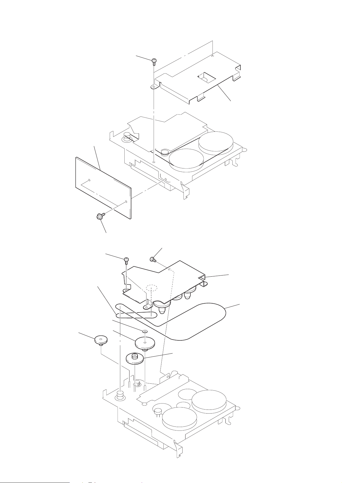
3-11. HOUSING
3
4
2
3-12. CHASSIS
8
5
belt (A)
2
1
6
7
1
9
3
4
belt (B)
– 10 –
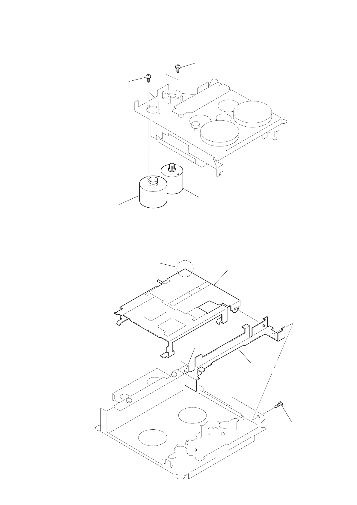
3-13. MOTOR (A)/(B) ASSY
2
motor (A) assy
1
3
4
motor (B) assy
3-14. HEAD PLATE
Note : On install, set the portions A and B.
B
3
A
2
– 11 –
1
 Loading...