

Page 1
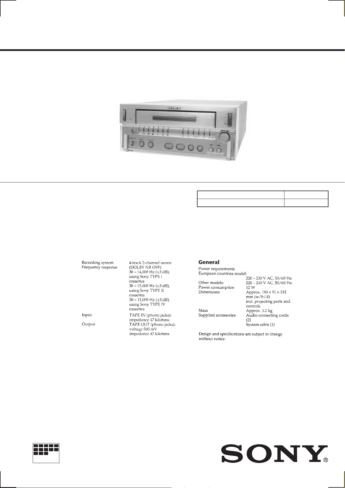
TC-SD1
SERVICE MANUAL
Manufactured under license from Dolby Laboratories
Licensing Corporation.
“DOLBY” and the double-D symbol a are trademarks
of Dolby Laboratories Licensing Corporation.
AEP Model
UK Model
E Model
Model Name Using Similar Mechanism TC-PX100
Tape Transport Mechanism Type TCM-ACLM572
SPECIFICATIONS
MICROFILM
STEREO CASSETTE DECK
Page 2

TABLE OF CONTENTS
1. GENERAL ·········································································· 3
2. DISASSEMBLY
2-1. Case, Front Panel································································ 4
2-2. Mechanism Deck (TCM-ACLM572)································· 5
2-3. Control Board, Dolby Board ·············································· 5
2-4. Power Trans Board, AC Select SW Board, Power Board··· 6
2-5. Tray Assembly···································································· 6
2-6. Mechanism Chassis Block·················································· 7
2-7. Capstan Reel Motor (M902)··············································· 7
3. DIAGRAMS
3-1. Circuit Boards Location ····················································· 8
3-2. Schematic diagram — Display Section —·························9
3-3. Printed Wiring Board — Display Section — ··················· 11
3-4. Printed Wiring Board — Main Section — ······················· 16
3-5. Schematic Diagram — Main Section — ·························· 21
3-6. IC Block Diagrams ··························································· 25
3-7. IC Pin Function Description·············································27
4. MECHANICAL ADJUSTMENT ································ 29
5. ELECTRICAL ADJUSTMENT ·································· 29
6. EXPLODED VIEWS
6-1. Case, Front Panel Section················································· 33
6-2. Chassis Section·································································34
6-3. Mechanism Deck Section-1 (TCM-ACLM572) ·············· 35
6-4. Mechanism Deck Section-2 (TCM-ACLM572) ·············· 36
6-5. Mechanism Deck Section-3 (TCM-ACLM572) ·············· 37
7. ELECTRICAL PARTS LIST······································· 38
SAFETY-RELATED COMPONENT WARNING!!
COMPONENTS IDENTIFIED BY MARK ! OR DOTTED LINE WITH
MARK ! ON THE SCHEMATIC DIAGRAMS AND IN THE PARTS
LIST ARE CRITICAL TO SAFE OPERATION. REPLACE THESE
COMPONENTS WITH SONY PARTS WHOSE PART NUMBERS
APPEAR AS SHOWN IN THIS MANUAL OR IN SUPPLEMENTS
PUBLISHED BY SONY.
— 2 —
Page 3
SECTION 1
GENERAL
This section is extracted
from instruction manual.
— 3 —
Page 4
SECTION 2
e
DISASSEMBLY
Note : Follow the disassembly procedure in the numerical order given.
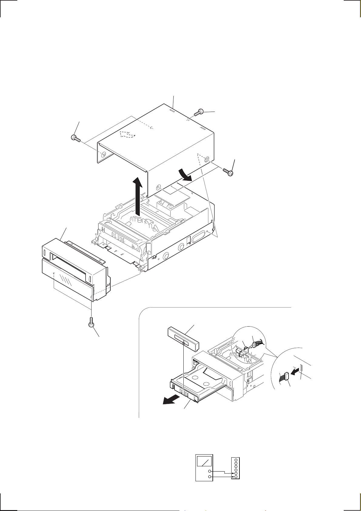
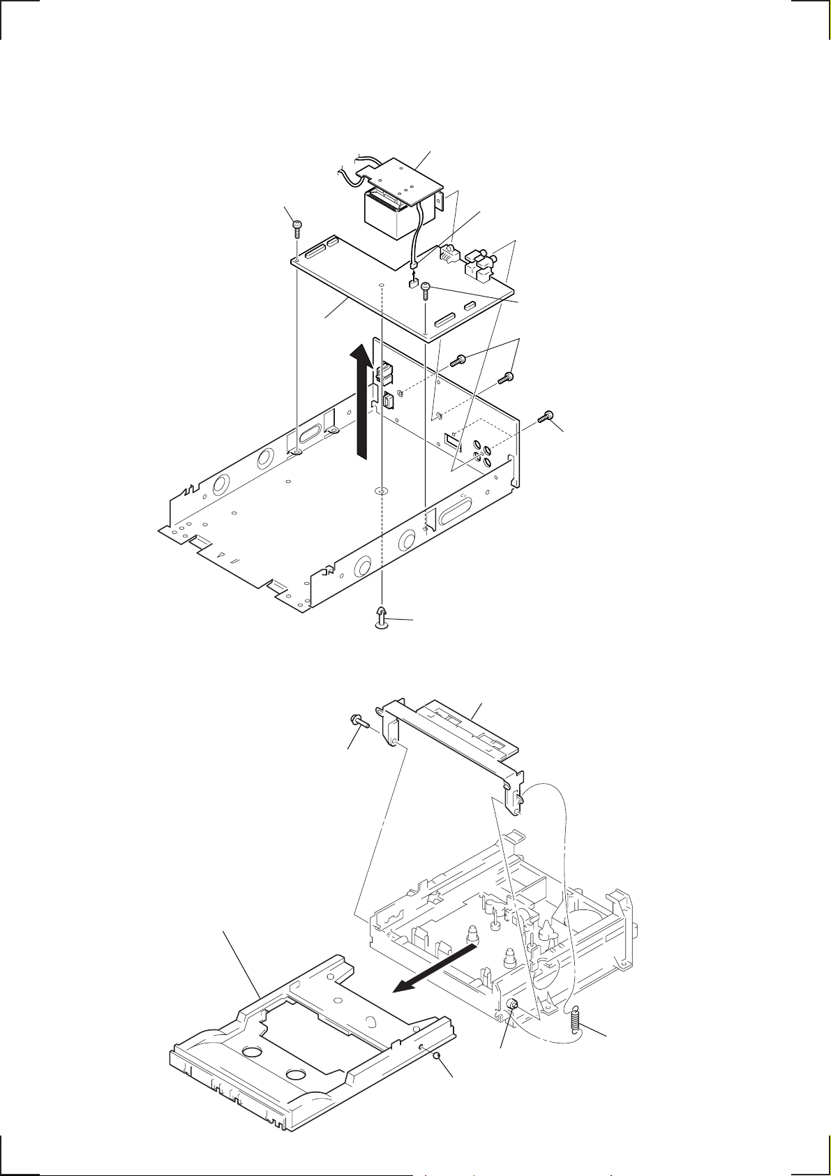
2-1. CASE, FRONT PANEL
4
Case
2
Two screws,
case stopper
3
Screw (+B 2.6 × 8)
1
Two screws,
case stopper
8
Front panel
7
Two screws
(+B 2.6
6
Loading panel
Connector
M901
×
8)
Rear sid
Pin-1
Pin-6
CN05
Connector
— 4 —
5
Slide the tray.
(Remove the connector from M901, supply the 6 V
power from an external regulated power supply to
pin-5 and pin-6 of CN05.)
Regulated DC
power supply
+
–
Pin-5
Pin-6
CN05
‘
’
1
6
Page 5
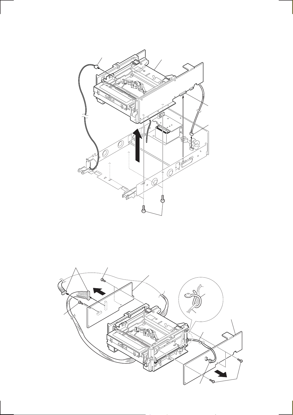
2-2. MECHANISM DECK (TCM-ACLM572)
r
4
Connector
5
Mechanism deck (TCM-ACLM572)
2
Connecto
3
Connector
2-3. CONTROL BOARD, DOLBY BOARD
3
Two screws
2
Two screws
(+B 2.6
1
Two connectors
×
8)
(+B 2.6
×
8)
1
Four screws
(+B 3
4
CONTROL board
×
10)
Clamper
Harness
Harness
Precaution for assembling :
Fix the harness with the clamper.
7
DOLBY board
— 5 —
5
Connector
6
Four screws
(+B 2.6
×
8)
Page 6
2-4. POWER TRANS BOARD, AC SELECT SW BOARD, POWER BOARD
)
3
POWER TRANS board
5
Screw (+B2.6 × 8)
8
POWER
board
1
Connector
6
Screw (+B2.6 × 8)
2
Two screws
(+PWH3
×
6)
4
Two screws
(+B3
×
10)
2-5. TRAY ASSEMBLY
5
Tray assembly
Note : Be careful not to drop
the stainless ball (5 DIA)
when removing the tray assembly.
1
Screw (1.7 × 8.2)
7
Suport
4
Arm (576)
— 6 —
3
Boss
Stainless ball (5 DIA)
2
Spring (B
Page 7
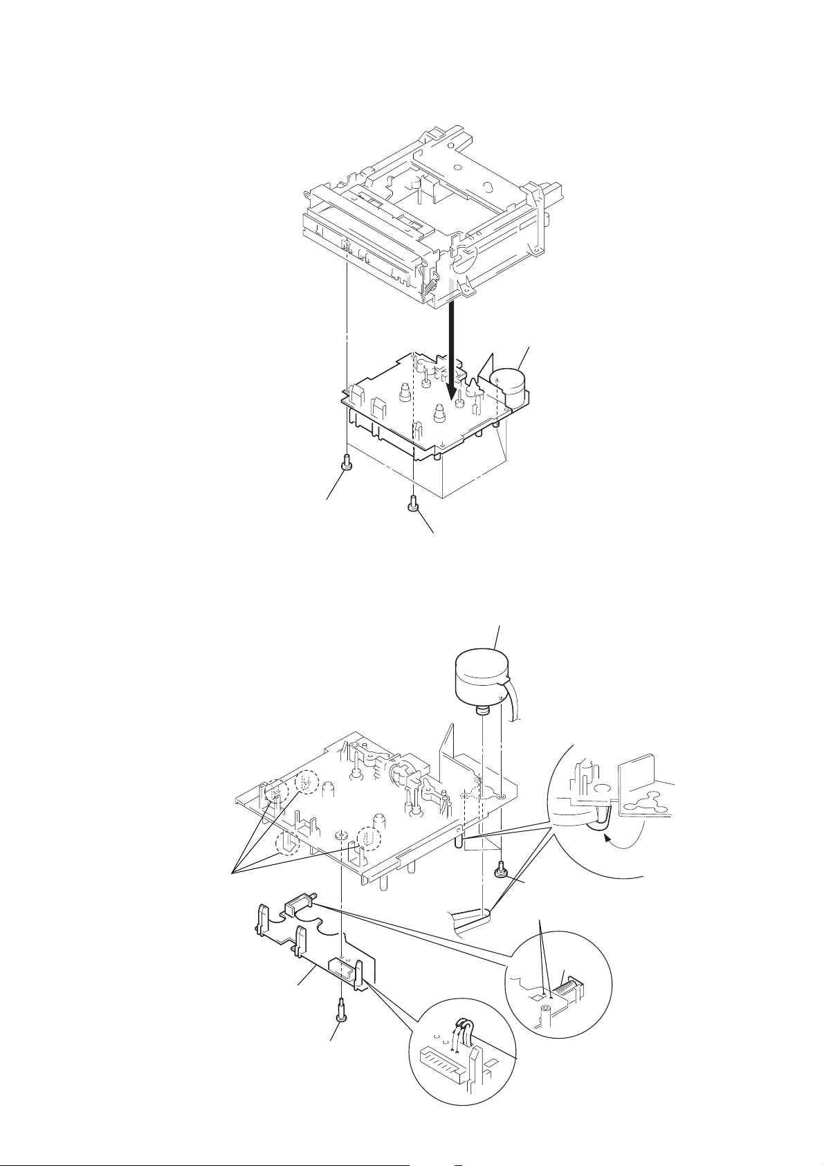
2-6. MECHANISM CHASSIS BLOCK
s
3
Mechanism chassi
1
Four screws (+P 3 × 6)
2-7. CAPSTAN REEL MOTOR (M902)
3
Claws (4 claws)
2
Screw (+P 3 × 8)
8
Capstan reel motor (M902)
7
Hook the belt.
6
Three screws for motor
1
Remove soldering of
the plunger solenoid
Plunger
solenoid
4
CONTROL board
2
Screw (stepped)
5
Remove soldering of
the motor lead wire.
— 7 — — 8
Page 8
SECTION 3
d
DIAGRAMS
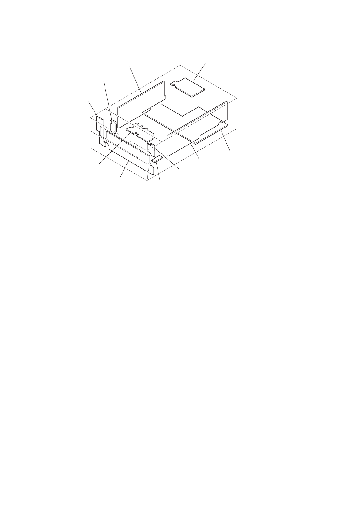
3-1. CIRCUIT BOARDS LOCA TION
REAR PANEL board
CONNECTION board
MODE CONTROL board
CONTROL board
FRONT board
POWER TRANS board
POWER boar
DOLBY board
O/C SW board
VR board
— 8 —
Page 9
TC-SD1
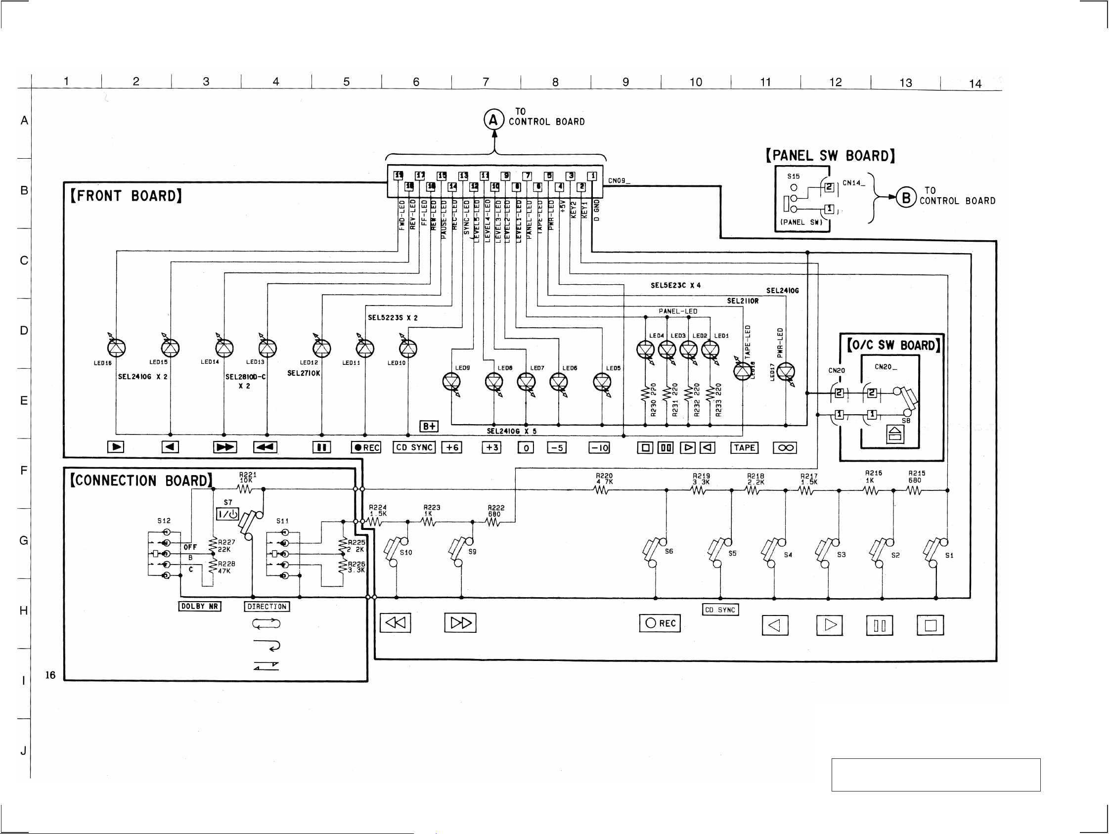
3-2. SCHEMATIC DIAGRAM — DISPLAY SECTION —
— 9 — — 10 —
Note on Schematic Diagram:
• All resistors are in Ω and 1/
specified.
• C : panel designation.
Note: The components identified by mark ! or dotted line
with mark ! are critical for safety.
Replace only with part number specified.
• U : B+ Line.
4
W or less unless otherwise
Page 10
3-3. PRINTED WIRING BOARD — DISPLAY SECTION —
TC-SD1
COMPONENT SIDE CONDUCTOR SIDE
• Refer to page 8 for Circuit Boards Location.
• Refer to page 24 for MODE CONTROL board Schematic Diagram.
Note on Printed Wiring Board:
• Y : parts extracted from the conductor side.
• b : Pattern of the rear side.
— 15 —— 14 —— 13 —— 12 —— 11 —
Page 11

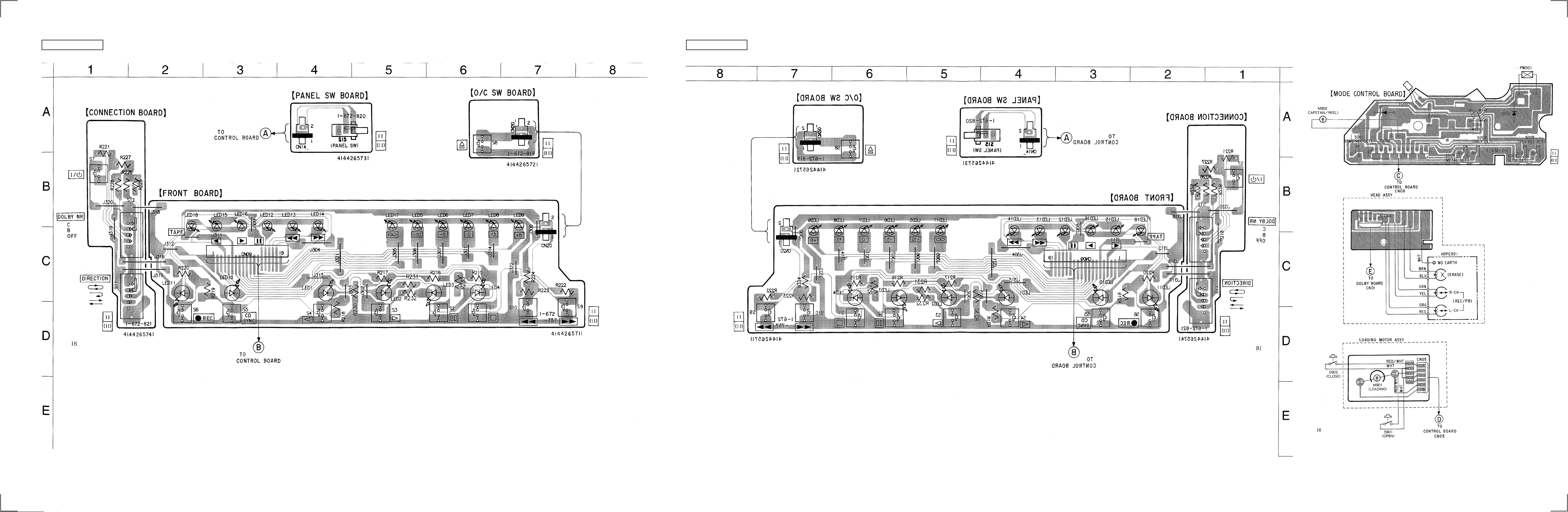
TC-SD1
3-4. PRINTED WIRING BOARD — MAIN SECTION —
COMPONENT SIDE CONDUCTOR SIDE
• Refer to page 8 for Circuit Boards Location.
Note on Printed Wiring Board:
• Y : parts extracted from the conductor side.
• b : Pattern of the rear side.
— 16 — — 17 — — 18 — — 19 — — 20 —
Page 12

TC-SD1
3-5. SCHEMATIC DIAGRAM — MAIN SECTION —
• Refer to page 25 for IC Block Diagrams. • Refer to page 27 for IC Pin Function Description. • Refer to page 15 for MODE CONTROL board Printed Wiring Board.
• Semiconductor Location
Ref. No. Location
D01 F-5
D02 B-1
D03 B-7
D04 B-7
D05 E-9
D06 E-10
D07 D-12
D12 F-14
D13 C-1
D14 A-1
D15 C-3
D16 B-3
D17 E-12
D19 B-3
D20 C-3
D22 E-14
D23 E-14
D24 E-12
D25 E-12
D28 D-2
D36 F-14
D37 F-15
IC01 F-5
IC02 F-9
IC03 F-1
IC04 G-13
IC05 C-6
IC06 C-1
IC07 D-5
IC08 C-2
IC10 G-14
IC11 E-15
Q01 F-7
Q02 G-7
Q03 E-9
Q04 E-8
Q05 G-10
Q05A H-15
Q06 G-9
Ref. No. Location
Q06A G-14
Q07 G-5
Q08 G-4
Q09 F-3
Q10 G-4
Q11 G-4
Q12 G-3
Q12A G-3
Q13 F-3
Q13A G-3
Q14 E-1
Q15 F-1
Q16 G-2
Q17 G-2
Q18 G-2
Q19 B-2
Q20 D-11
Q21 B-3
Q22 C-2
Q23 C-2
Q24 C-2
Q25 D-2
Q26 C-3
Q27 D-3
Q29 C-7
Q30 C-7
Q31 C-7
Q32 C-7
Q33 C-7
Q34 D-7
Q35 C-6
Q36 C-6
Q37 B-12
Q38 C-7
Q39 G-12
Q40 G-12
Q41 H-13
Q42 B-12
Q43 C-13
Q44 E-14
Q45 G-10
Note on Schematic Diagram:
• All capacitors are in µF unless otherwise noted. pF: µµF
50 WV or less are not indicated except for electrolytics
and tantalums.
• All resistors are in Ω and 1/
specified.
• C : panel designation.
Note: The components identified by mark ! or dotted line
with mark ! are critical for safety.
Replace only with part number specified.
• U : B+ Line.
• V : B– Line.
• H : adjustment for repair.
• Voltages and waveforms are dc with respect to ground
under no-signal (detuned) conditions.
no mark : REC/PB
( ) : REC
< > : PB
[ ] : STOP
• Voltages are tak en with a V OM (Input impedance 10 M Ω).
Voltage v ariations may be noted due to normal production
tolerances.
• Waveforms are taken with a oscilloscope.
Voltage v ariations may be noted due to normal production
tolerances.
• Circled numbers refer to waveforms.
• Signal path.
E : PB
a : REC
4
W or less unless otherwise
— 21 — — 22 — — 23 — — 24 —
Page 13

3-6. IC BLOCK DIAGRAMS
GHCAL
GPCAL
GL
GH
GP
RECCALNCREC IN
REF
BOOST
VCC
REC OUT
VEE
REC OUT
2021222324 19 18 17 16 15 14 13
12
11
F/Q
FQ
FM
FPCAL
DGND
MUTE
NC
REC IN
GND
BOOST
1 2 3 4 5 6 7 8 9 10
PARA
METER
CTRL
IC02 CXA1561S
VCT
22 21 20 19
PBIN1
LINEIN1
MPXIN1
MPXOUT1
18 17 16
LINEOUT1
SSK
TCH1
CC
TCL1
15
RECOUT1
14 13 12
REC AMP
MODE
V
V
CC
IREF
1 2 3 4
IREF
PBIN2
LINEIN2
IC01 µPC4570HA
1
2
VCC
OUT1
5
3
4
6
8
7
VEE
–IN1
+IN1
–IN2
OUT2
+IN2
MOA
MOA
MPXIN2
HLS HDET LDET LLS
HLS
SSK
5 6 7
MPXOUT2
HDET LDET LLS
TCH2
LINEOUT2
8
REC AMP
9 10 11
TCL2
RECOUT2
Mode
Control
NRSW
EE
V
EE
V
IC03 CXA1598S
9
VCC
— 25 —
Page 14

IC04 LA5617
ON/OFF
ERROR
AMP
2 3
1
VO1
VCC
IC06 LB1641
VREF
CN1
4
EN
CURRENT
LIMITER
VMUTE VCC
VCC
CURRENT
LIMITER
~_
~_
5 6 7 8 9
GND
EN DISPLAY
ON/OFF
140uA
COMPARATER
VREF
1.8V
NC
CN2
ERROR
AMP
START
CIRCUIT
VREF
OVER HEAT
PROTECT
VEE
10
VO2
T.S.D O.C.P
NOISE
MOTOR
DRIVE
FILTER
MOTOR
DRIVE
FWD/REV/STOP
CONTROL LOGIC
2 3
1
GND
DRIVE
MOTOR
NOISE
FILTER
5 6 7 8 9 10
4
VCC 1
FWD.IN
REV.IN
CLAMP
VCC 2
DRIVE
MOTOR
— 26 —
Page 15

3-7. IC PIN FUNCTION DESCRIPTION
• CONTROL BOARD IC05 TMP87CH48DF (SYSTEM CONTROL)
Pin No.
1
2
3
4
5
6
7
8
9
10
11
12
13
14
15
16
17
18
19
20
21
22
23
24
25
26
27
28
29
30
31
32
33
34
35
36
37
38
39
40
41
42
43
44
45
Pin Name
VSS
OSC-OUT
OSC-IN
RESET
NC
NC
TEST
POWER-IN
POWER-OUT
TYPE4
TYPE2
TYPE1
CHROM-SW
METAL-SW
REC.FWD-SW
REC.REW-SW
MODE-SW
I2C-CLOCK
I2C-DATA
OPEN-SW
CLOSE-SW
TEST
SOLENOIDE
CAPSTAN
OPEN-M
CLOSE-M
PANEL-SW
OP-VERSION
NC
AD-GND
AD-REF
VCC
KEY1
KEY2
HALF-SW
AMS-IN
PULSE
METER-L/R
I2C-BUSY
SYS
REC/PB
RELAY
BIAS
LINE MUTE
REC MUTE
I/O
—
System ground terminal
O
System clock output (8 MHz)
I
System clock input (8 MHz)
I
Reset input
—
No used
—
No used
I
Test terminal
I
Primary power supply ON/OFF input
O
Mechanism. AU power supply ON/OFF output
O
Type 4 recording bias selector output
O
Type 2 recording bias selector output
O
Type 1 recording bias selector output
I
Tape type 2 input
I
Tape type 4 input
I
Record safety tab input of side A
I
Record safety tab input of side A
I
Head sensor input
I/O
12C clock input/output
I/O
12C data input/output
I
Loader open switch input
I
Loader close switch input
I
TEST input
O
Solenoid output
O
Capstan motor output
O
Loader open (motor) output
O
Loader close (motor) output
I
Panel switch input
I
Option TC version input
—
No used
—
AD ground terminal
—
AD reference voltage
—
System power input
I
Key 1 input
I
Key 2 input
I
Half switch input
I
AMS input
I
Pulse input
I
Meter L-CH input
I/O
I2C BUSY input/output
—
No used
O
REC/PB selector output
O
RELAY selector output
O
Bias selector output
O
LINE mute selector output
O
Record mute selector output
Description
— 27 —
Page 16

Pin No.
46
47
48
49
50
51
52
53
54
55
56
57
58
59
60
61
62
63
64
Pin Name
PB MUTE
DOLBY ON/OFF
DOLBY B/C
STB-R-LED
STB-G-LED
P ANEL-LED
LEBEL1-LED
LEVEL2-LED
LEVEL3-LED
LEVEL4-LED
LEVEL5-LED
T APE-LED
CDSYNC-LED
REC-LED
P AUSE-LED
REW-LED
FF-LED
REV -LED
FWD-LED
I/O
O
Playback mute selector output
O
Dolby ON/OFF output
O
Dolby B/C output
O
No used
O
Power ON LED (green) output
O
Panel LED (blue) output
O
Level meter 1 (minimum dB) LED (green) output
O
Level meter 2 LED (green) output
O
Level meter 3 LED (green) output
O
Level meter 4 LED (red) output
O
Level meter 5 (maximum dB) LED (red) output
O
Tape indicator LED (amber) output
O
CD synchro LED (red) output
O
REC LED (red) output
O
PAUSE LED (orange) output
O
REW LED (amber) output
O
FF LED (amber) output
O
REV LED (green) output
O
FWD LED (green) output
Description
— 28 —
Page 17

SECTION 4
MECHANICAL ADJUSTMENT
SECTION 5
ELECTRICAL ADJUSTMENT
Precaution
1. Clean the following parts with a denatured alcohol-moistened
swab:
record/playback heads pinch rollers
erase head rubber belts
capstan idlers
2. Do not use a magnetized screwdriver for the adjustments.
3. After the adjustments, apply suitable locking compound to the
parts adjusted.
4. The adjustments should be performed with the rated power
supply voltage unless otherwise noted.
• Torque Measurement
Mode
FWD
FWD
back tension
REV
REV
back tension
FF/REW
• Tape Tension
FWD tension
REV tension
Torque meter
CQ-102C
CQ-102RC
CQ-201B
CQ-403A
CQ-403R
Meter reading
31 to 61 g • cm
2 to 6 g • cm
36 to 61 g • cm
2 to 6 g • cm
61 to 143 g • cm
100 g or more
100 g or more
Precaution
1. Perform adjusting on the test mode.
2. Demagnetize the record/playback head with a head
demagnetizer.
3. Do not use a magnetized screwdriver for the adjustments.
4. After the adjustments, apply suitable locking compound to the
parts adjust.
5. The adjustments should be performed with the rated power
supply voltage unless otherwise noted.
6. The adjustments should be performed in the order given in this
service manual. (As a general rule, playback circuit adjustment
should be completed before performing recording circuit
adjustment.)
7. The adjustments should be performed for both L-CH and RCH.
8. Switches should be set as follows.
DOLBY NR..................................................................... OFF
DIRECTION ....................................................................A
• Standard Recording Position
Adjust the REC LEVEL (VR02) control so that the standard input/
output signal level is obtained in the following connection.
— Record Mode —
audio oscillator
level meter
10k
600
Ω
Ω
LINE IN
attenuator
Standard Input Level
Input terminal LINE IN
source impedance 10kΩ
input signal level 0.5V (–3.8dB)
Standard Output Level
Output terminal LINE OUT
load impedance 47kW
output signal level 0.5V (–3.8dB)
0dB = 0.775 V
Test Mode
Turn OFF the main power and insert the shorting plug to the test
point CN13 (2P) on the CONTROL board (setting IC05 pin 22 to
“L”). Then turn ON the main power which activ ate the TEST mode.
All displays flash once.
If a recording is performed in the TEST mode, the REC MEMOR Y
mode becomes active at the moment of recording so that the tape is
rewound by the amount of recording when a tape is rewound after
recording.
After adjustment, be sure to remove the shorting plug from the test
point CN13 (2P).
set
47k
Ω
LINE OUT
Test Tape
— 29 —
Type Signal Used for
P-4-A100 10 kHz, –10 dB Azimuth Adjustment
WS-48B 3 kHz, 0 dB Tape Speed Adjustment
P-4-L300 315 Hz, 0 dB PB Level Adjustment
Page 18

B
t
r
Record/Playback Head Azimuth Adjustment
)
r
Note: • Perform this adjustment after the head is turned around.
(If the head is positioned in the FWD direction, turn around
the head and start adjustment from the REV mode as
described below.)
* When the azimuth adjustment is performed, the azimuth
adjustment screw must end up with rotation of tightening
direction (i.e. clockwise direction).
Adjustment procedure :
1. Mode: REV playback
test tape
P-4-A100
(10kHz, –10dB)
47k
set
LINE OUT
level mete
Ω
4. Enter the FWD mode and perform steps 1 to 3.
5. Check that the phase difference between L-CH and R-CH is in
the range of in-phase to 90°.
6. After adjustment, lock the screw with locking compound.
Oscilloscope Lissajous waveform
in phase 45
°
90
°
135
°
Good Wrong
180
°
Adjustment Location:
2. Turn the azimuth adjustment screw for the maximum output
level of L-CH and R-CH.
If the peak levels do not match for L-CH and R-CH, turn the
adjustment screw until both of output levels match together
within 1 dB of peak.
L-CH peak
screw position
output
level
R-CH peak
within
1dB
L-CH peak
R-CH peak
within 1d
angle of
adjustmen
screw
3. Phase Check
Mode: REV playback
Adjustment screw (FWD side) Adjustment screw (REV side
Tape Speed Adjustment
Procedure :
Mode : FWD playback
test tape
WS-48B (3kHz, 0dB)
47k
set
L- or R-CH of LINE OUT
frequency counte
Ω
1. Enter the FWD playback mode, and play back test tape.
2. Adjust the adjustment control (variable resistor) of the motor
(M902) until the frequency counter reading becomes 3,000 Hz
± 90 Hz.
3. Confirm that the tape speed deviation between tape top and tape
end is within 3%.
Adjustment location :
test tape
P-4-A100
(10kHz, –10dB)
R-CH
set
L-CH
47k
Ω
47k
Ω
LINE OUT
oscilloscope
V H
— 30 —
M902
adjustment control
(variable resistor)
Sample Value of Wow and flutter
W. RMS (JIS) within 0.3%
(test tape: WS-48B)
Page 19

Playback Level Adjustment
e
r
Procedure :
1. Mode : FWD playback
test tape
P-4-L300
(315Hz, 0dB)
set
LINE OUT
level meter
Record Level Adjustment
Setting :
• The REC LEVEL control must be positioned at the standard record
level position. (Refer to page 29.)
Procedure :
1. Record
AF OSC
attenuator
600
set
Ω
blank tape
CS-123
Adjust SFR01 (L-CH) and SFR02 (R-CH) so that the reading on
level meter meets the adjustment limits below.
Adjustment Limits :
LINE OUT level : -7.7 ± 0.5 dB (301.5 to 338.5 mV)
Level difference between channels : within 0.5 dB
Check that the LINE OUT level does not change even if Playback
and Stop operations are repeated several times.
Adjustment Location : DOLBY board (Refer to page 32.)
Record BIAS Adjustment
Setting :
• The REC LEVEL control must be positioned at the standard record
level position. (Refer to page 29.)
Procedure :
1. Mode: Record
AF OSC
attenuator
Ω
600
LINE IN
1) 315Hz
2) 10kHz
set
50mV (– 23.8dB)
blank tap
CS-123
LINE IN
315Hz, 50mV (–23.8dB)
2. Playback
recorded portion
set
LINE OUT
level meter
3. Reproduce the portion of tape which is recorded in step 1.
Confirm that the playback level stays within the specified range
of the Adjustment Level.
4. If the playback level is outside the specified range, adjust the
SFR11 (L-CH) and SFR12 (R-CH), and repeat steps 1 to 3 until
the specified range is satisfied.
Adjustment Level : -23.8 dB ± 0.5 dB (47.3 to 53.1 mV)
Adjustment Location : DOLBY board (Refer to page 32.)
2. Playback
recorded portion
set
LINE OUT
level mete
3. Reproduce the portion of tape which is recorded in step 1.
Confirm that the playback level stays within the specified range
of the Adjustment Level.
4. If the playback level is outside the specified range, adjust the
SFR03 (L-CH) and SFR04 (R-CH), and repeat steps 1 to 3 until
the specified range is satisfied.
Adjustment Level : Difference of the playback level between
10 kHz and 315 Hz : 0 dB ± 0.5 dB when 315 Hz is the reference.
Adjustment Location : DOLBY board (Refer to page 32.)
— 31 —
Page 20

Adjustment Location:
DOLBY board (Component Side)
SFR12
SFR11
SFR03
SFR04
SFR01
IC02
SFR02
IC03
CONTROL board (Component Side)
IC01
CN13
IC05
— 32 —
Page 21

NOTE:
• -XX, -X mean standardized parts, so they may
have some differences from the original one.
• Items marked “*” are not stocked since they
are seldom required for routine service. Some
delay should be anticipated when ordering these
items.
SECTION 6
EXPLODED VIEWS
• The mechanical parts with no reference number
in the exploded views are not supplied.
• Hardware (# mark) list and accessories and
packing materials are given in the last of this
parts list.
• Abbreviations
HK : Hong Kong
SP : Singapore
The components identified by mark ! or
dotted line with mark ! are critical for safety .
Replace only with part number specified.
6-1. CASE, FRONT PANEL SECTION
10
9
3
8
7
31
#1
18
5
2
4
#3
1
4
2
19
#1
#3
17
20
16
11
#1
21
15
12
#1
11
13
#5
13
22
23
24
#4
#1
6
26
27
28
13
14
#4
14
25
#1
14
#4
Ref. No. Part No. Description Remarks Ref. No. Part No. Description Remarks
1 3-033-056-01 WINDOW, GLASS
2 4-212-579-11 BRACKET (GLASS)
3 4-942-636-21 EMBLEM (NO.3.5), SONY
4 4-214-458-01 TAPE
5 3-033-074-01 CHASSIS, FRONT
6 3-033-079-01 REC LEVEL KNOB
7 3-028-756-01 PANEL (AL-TC), LOADING
8 3-033-054-01 PLATE, LOADING ORNAMENT
9 3-033-055-01 LID, LOADING
10 3-028-755-01 PANEL (AL-TC), FRONT
11 3-033-057-01 SCREW, CASE STOPPER
* 12 3-033-052-01 TOP COVER
* 13 3-033-053-01 FOOT
14 3-033-061-01 FOOT CUSHION
15 1-773-128-11 WIRE (FLAT TYPE) (19 CORE)
* 16 A-2007-825-A CONNECTION BOARD, COMPLETE
17 3-033-080-01 DOLBY KNOB
18 3-033-078-01 DIRECTION KNOB
19 4-212-557-01 BUTTON (REC)
20 3-033-075-01 LENS
* 21 A-2007-817-A FRONT BOARD, COMPLETE
22 3-033-076-01 BUTTON, PLAY
23 3-033-077-01 BUTTON, FF
* 24 A-2007-823-A O/C SW BOARD, COMPLETE
* 25 1-672-765-11 VR BOARD
26 3-033-081-01 REC LEBEL BRACKET
27 3-033-082-01 VR WASHER 9Q
28 3-033-083-01 NUT, VR
31 4-212-539-02 BUTTON (POWER)
— 33 —
Page 22

6-2. CHASSIS SECTION
#1
58
#1
59
57
TCM-ACLM572
#3
#6
66
54
56
#6
53
not supplied
#6
55
#1
#6
#6
#1
T01
A
63
64
60
65
#7
#7
62
#6
#1
A
61
not supplied
#6
52
Ref. No. Part No. Description Remarks Ref. No. Part No. Description Remarks
51 3-033-060-01 SPRING, PLATE
52 4-213-692-02 TAPE (SPRING)
53 X-4950-381-1 BRACKET (R) ASSY
54 3-033-050-01 HINGE (L/C), DOOR
* 55 A-2007-818-A DOLBY BOARD, COMPLETE
* 56 3-033-063-01 CHASSIS (R), DECK
* 57 3-033-062-01 CHASSIS (L), DECK
* 58 A-2007-819-A CONTROL BOARD, COMPLETE
51
* 59 A-2007-820-A POWER BOARD, COMPLETE
* 60 1-672-764-11 POWER TRANS BOARD
* 61 3-035-607-01 REAR PANEL (AEP, UK)
* 61 3-035-608-01 REAR PANEL (E, HK, SP)
* 62 3-033-068-01 CUSHION
! 63 1-555-750-00 CORD, POWER
64 3-033-071-01 STOPPER, AC CORD
! 65 1-526-794-11 OUTLET, AC
* 66 A-2007-824-A PANEL SW BOARD, COMPLETE
! T01 1-433-657-11 TRANSFORMER, POWER
— 34 —
#1
not supplied
The components identified by mark ! or dotted
line with mark ! are critical for safety.
Replace only with part number specified.
Page 23

6-3. MECHANISM DECK SECTION-1 (TCM-ACLM572)
#10
102
#10
106
105
103
#11
104
107
118
117
108
118
#13
S902
119
116
109
120
122
115
114
#14
121
S901
#12
#13
110
111
M901
112
116
113
#8
#9
101
Ref. No. Part No. Description Remarks Ref. No. Part No. Description Remarks
101 3-017-214-01 HOLDER
102 3-017-215-01 ARM (A)
103 3-017-233-01 RACK, GEAR
104 3-017-216-01 ARM (C)
105 3-017-213-01 CHASSIS
106 3-017-212-01 TRAY
107 3-017-235-01 SPRING (A)
108 3-017-244-01 SCREW (1.7 × 8.2), SPECIAL
109 3-017-217-01 ARM (576)
110 3-017-218-01 RETAINER
114 3-017-234-01 GROUND, PLATE
115 3-017-243-01 NUT
116 3-017-242-01 BUFFER
117 3-017-232-01 GEAR (B)
118 3-017-241-01 SCREW (1.6 × 4), SPECIAL
119 3-017-237-01 BELT (49.2)
120 3-017-231-01 PULLEY (C)
121 3-017-220-01 ARM
122 3-017-240-01 SCREW (2.1 × 4), SPECIAL
M901 3-017-239-01 PULLEY (MOTOR) (LOADING)
111 3-017-219-01 PLATE
112 3-017-211-01 FRAME
113 3-017-236-01 SPRING (B)
S901 3-017-238-01 LIMITTER (SW MSS-8B) (OPEN)
S902 3-017-238-01 LIMITTER (SW MSS-8B) (CLOSE)
— 35 —
Page 24

6-4. MECHANISM DECK SECTION-2 (TCM-ACLM572)
158
157
155
156
159
154
not supplied
153
not
supplied
161
155
160
155
HRPE901
M902
155
A
162
163
164
A
not
supplied
165
155
166
not supplied
167
151
Ref. No. Part No. Description Remarks Ref. No. Part No. Description Remarks
151 3-017-294-01 SCREW (S), SPECIAL
153 3-017-273-01 LEVER (AC), SPRING
154 3-017-270-01 AC, LEVER
155 3-017-279-01 SCREW (M2), SPECIAL
156 3-017-274-01 HEAD, SPRING BASE
161 3-017-300-01 WASHER, FLAT
162 3-017-255-01 PINCH ROLLER (R)
163 3-017-296-01 CUSHION (MOTOR)
164 3-017-297-01 SCREW (MOTOR)
165 3-017-280-01 SCREW (M2 TAPPING), SPECIAL
157 3-017-254-01 PINCH ROLLER (F)
158 3-017-253-01 CHASSIS (HEAD)
159 3-017-277-01 PINCH (F), SPRING
160 3-017-278-01 PINCH (R), SPRING
166 3-017-285-01 BELT (MAIN)
* 167 1-672-011-11 MODE CONTROL BOARD
HRPE9013-017-303-01 HEAD (REC/PLAY/ERASE)
M902 3-017-259-01 PULLEY (MOTOR) (CAPSTAN REEL)
— 36 —
Page 25

6-5. MECHANISM DECK SECTION-3 (TCM-ACLM572)
216
214
217
213
212
214
213
215
211
211
218
219
221
220
222
223
210
224
209
208
225
224
209
203
208
207
206
205
204
226
227
202
201
Ref. No. Part No. Description Remarks Ref. No. Part No. Description Remarks
201 3-017-258-01 FLYWHEEL (R)
202 3-017-257-01 FLYWHEEL (F)
203 3-017-284-01 BELT (SUB)
204 3-017-265-01 IDLER, GEAR
205 3-017-305-01 GEAR (P)
214 3-017-262-01 REEL, BUSHING
215 3-017-272-01 SPRING (BT)
216 3-017-281-01 WASHER, FLAT
217 3-017-256-01 ARM (PLAY)
218 3-017-275-01 LOCK, SPRING CAM
206 3-017-283-01 WASHER, FLAT
207 3-017-304-01 CLUTCH
208 3-017-263-01 REEL, BASE
209 3-017-295-01 WASHER, FLAT
210 3-017-252-01 CHASSIS (OS)
211 3-017-298-01 WASHER (B/T)
212 3-017-299-01 SPRING (B/T) (F)
213 3-017-288-01 REEL, CAP
219 3-017-267-01 LOCK, ARM CAM
220 3-017-282-01 WASHER, FLAT
221 3-017-264-01 CAM, GEAR
222 3-017-266-01 BASE, LEVER
223 3-017-268-01 ARM (RF)
224 3-017-269-01 GEAR (RF)
225 3-017-276-01 ARM (RF), SPRING
226 3-017-293-01 MAGNET, PLATE
227 3-017-271-01 CAP (MG)
— 37 —
Page 26

CONNECTION
CONTROL
NOTE:
• Due to standardization, replacements in the
parts list may be different from the parts
specified in the diagrams or the components
used on the set.
• -XX, -X mean standardized parts, so they
may have some difference from the original
one.
• Items marked “*” are not stocked since they
are seldom required for routine service.
Some delay should be anticipated when
ordering these items.
Ref. No. Part No. Description Remarks Ref. No. Part No. Description Remarks
* A-2007-825-A CONNECTION BOARD, COMPLETE
***************************
< RESISTOR >
R221 1-247-855-11 CARBON 10K 5% 1/4W
R225 1-247-839-11 CARBON 2.2K 5% 1/4W
R226 1-247-843-11 CARBON 3.3K 5% 1/4W
R227 1-247-863-11 CARBON 22K 5% 1/4W
R228 1-247-871-11 CARBON 47K 5% 1/4W
ELECTRICAL PARTS LIST
• CAPACITORS:
uF: µF
• RESISTORS
All resistors are in ohms.
METAL: metal-film resistor
METAL OXIDE: Metal Oxide-film resistor
F: nonflammable
• COILS
uH: µH
• Abbreviations
HK : Hong Kong
SP : Singapore
SECTION 7
• SEMICONDUCTORS
In each case, u: µ, for example:
uA...: µA... , uPA... , µPA... ,
uPB... , µPB... , uPC... , µPC... ,
uPD..., µPD...
When indicating parts by reference number,
please include the board name.
The components identified by mark ! or
dotted line with mark ! are critical for safety .
Replace only with part number specified.
< CONNECTOR >
* CN05 1-564-708-11 PIN, CONNECTOR (SMALL TYPE) 6P
CN07 1-785-785-11 SOCKET, CONNECTOR 10P
* CN08 1-564-715-11 PIN, CONNECTOR (SMALL TYPE)13P
CN09 1-568-802-11 SOCKET, CONNECTOR 19P
CN12 1-785-779-11 SOCKET, CONNECTOR 13P
CN12A 1-785-780-11 HEADER, PIN 13P
* CN14 1-564-704-11 PIN, CONNECTOR (SMALL TYPE) 2P
< SWITCH >
S7 1-572-647-11 SWITCH, KEY BOARD (POWER)
S11 1-692-505-11 SWITCH, SLIDE (DIRECTION)
S12 1-692-505-11 SWITCH, SLIDE (DOLBY NR)
************************************************************
* A-2007-819-A CONTROL BOARD, COMPLETE
************************
< CAPACITOR >
C68 1-162-282-31 CERAMIC 100PF 10% 50V
C69 1-137-372-11 FILM 0.022uF 5% 50V
C70 1-162-217-31 CERAMIC 56PF 5% 50V
C71 1-126-961-11 ELECT 2.2uF 20% 50V
C73 1-126-960-11 ELECT 1uF 20% 50V
C74 1-126-916-11 ELECT 1000uF 20% 6.3V
C75 1-161-494-00 CERAMIC 0.022uF 25V
C76 1-126-964-11 ELECT 10uF 20% 50V
C77 1-164-159-11 CERAMIC 0.1uF 50V
C78 1-162-306-11 CERAMIC 0.01uF 20% 16V
C79 1-162-306-11 CERAMIC 0.01uF 20% 16V
C81 1-126-935-11 ELECT 470uF 20% 16V
C82 1-126-934-11 ELECT 220uF 20% 16V
C83 1-162-282-31 CERAMIC 100PF 10% 50V
C70A 1-126-964-11 ELECT 10uF 20% 50V
C74A 1-164-159-11 CERAMIC 0.1uF 50V
C76A 1-126-963-11 ELECT 4.7uF 20% 50V
C76B 1-104-664-11 ELECT 47uF 20% 16V
C77A 1-164-159-11 CERAMIC 0.1uF 50V
< DIODE >
D02 8-719-911-19 DIODE 1SS119
D03 8-719-911-19 DIODE 1SS119
D04 8-719-911-19 DIODE 1SS119
D13 8-719-109-97 DIODE RD6.8ES-B2
D14 8-719-109-85 DIODE RD5.1ES-B2
D15 8-719-911-19 DIODE 1SS119
D16 8-719-109-85 DIODE RD5.1ES-B2
D19 8-719-055-76 DIODE 1N4148
D20 8-719-911-19 DIODE 1SS119
D28 8-719-200-02 DIODE 10E2
< IC >
IC05 8-759-575-34 IC TMP87CH48DF-4B67
IC06 8-759-822-09 IC LB1641
IC07 8-759-165-85 IC PST600H-T
IC08 8-759-710-59 IC NJM4580D-D
< TRANSISTOR >
Q19 8-729-119-76 TRANSISTOR 2SA1175-HFE
Q21 8-729-900-63 TRANSISTOR DTA124ES
Q22 8-729-900-63 TRANSISTOR DTA124ES
Q23 8-729-900-63 TRANSISTOR DTA124ES
Q24 8-729-993-43 TRANSISTOR 2SA934R
Q25 8-729-993-43 TRANSISTOR 2SA934R
Q26 8-729-029-86 TRANSISTOR DTC124ESA
Q27 8-729-029-86 TRANSISTOR DTC124ESA
Q29 8-729-900-63 TRANSISTOR DTA124ES
Q30 8-729-900-63 TRANSISTOR DTA124ES
< FILTER >
CF01 1-579-125-11 VIBRA TOR, CERAMIC 8MHz
Q31 8-729-900-63 TRANSISTOR DTA124ES
Q32 8-729-900-63 TRANSISTOR DTA124ES
Q33 8-729-900-63 TRANSISTOR DTA124ES
Q34 8-729-900-63 TRANSISTOR DTA124ES
Q35 8-729-900-63 TRANSISTOR DTA124ES
Q36 8-729-900-63 TRANSISTOR DTA124ES
Q38 8-729-900-63 TRANSISTOR DTA124ES
— 38 —
Page 27

CONTROL DOLBY
Ref. No. Part No. Description Remarks Ref. No. Part No. Description Remarks
< RESISTOR >
R76 1-249-437-11 CARBON 47K 5% 1/4W
R77 1-249-427-11 CARBON 6.8K 5% 1/4W F
R78 1-247-843-11 CARBON 3.3K 5% 1/4W
R79 1-247-879-11 CARBON 100K 5% 1/4W
R80 1-247-879-11 CARBON 100K 5% 1/4W
R81 1-247-855-11 CARBON 10K 5% 1/4W
R82 1-249-417-11 CARBON 1K 5% 1/4W F
R83 1-249-432-11 CARBON 18K 5% 1/4W
R84 1-249-436-11 CARBON 39K 5% 1/4W
R85 1-247-879-11 CARBON 100K 5% 1/4W
R86 1-249-417-11 CARBON 1K 5% 1/4W F
R87 1-249-413-11 CARBON 470 5% 1/4W F
R88 1-247-855-11 CARBON 10K 5% 1/4W
R89 1-247-855-11 CARBON 10K 5% 1/4W
R90 1-249-417-11 CARBON 1K 5% 1/4W F
R91 1-249-417-11 CARBON 1K 5% 1/4W F
R96 1-247-855-11 CARBON 10K 5% 1/4W
R97 1-249-417-11 CARBON 1K 5% 1/4W F
R98 1-247-855-11 CARBON 10K 5% 1/4W
R99 1-249-417-11 CARBON 1K 5% 1/4W F
R100 1-247-807-11 CARBON 100 5% 1/4W
R101 1-247-855-11 CARBON 10K 5% 1/4W
R102 1-247-847-11 CARBON 4.7K 5% 1/4W
R103 1-247-807-11 CARBON 100 5% 1/4W
R104 1-249-427-11 CARBON 6.8K 5% 1/4W F
R105 1-249-427-11 CARBON 6.8K 5% 1/4W F
R107 1-249-398-11 CARBON 27 5% 1/4W F
R109 1-247-867-11 CARBON 33K 5% 1/4W
R110 1-247-807-11 CARBON 100 5% 1/4W
R111 1-247-879-11 CARBON 100K 5% 1/4W
R112 1-249-430-11 CARBON 12K 5% 1/4W
R113 1-249-440-11 CARBON 82K 5% 1/4W
R114 1-249-417-11 CARBON 1K 5% 1/4W F
R116 1-249-427-11 CARBON 6.8K 5% 1/4W F
R117 1-249-412-11 CARBON 390 5% 1/4W F
R20A 1-247-855-11 CARBON 10K 5% 1/4W
R200 1-249-412-11 CARBON 390 5% 1/4W F
R201 1-249-412-11 CARBON 390 5% 1/4W F
R202 1-249-412-11 CARBON 390 5% 1/4W F
R203 1-249-412-11 CARBON 390 5% 1/4W F
R204 1-249-409-11 CARBON 220 5% 1/4W F
R205 1-249-409-11 CARBON 220 5% 1/4W F
R206 1-249-412-11 CARBON 390 5% 1/4W F
R207 1-249-412-11 CARBON 390 5% 1/4W F
R208 1-249-412-11 CARBON 390 5% 1/4W F
R209 1-249-412-11 CARBON 390 5% 1/4W F
R210 1-249-412-11 CARBON 390 5% 1/4W F
R211 1-249-412-11 CARBON 390 5% 1/4W F
R212 1-249-412-11 CARBON 390 5% 1/4W F
R214 1-249-412-11 CARBON 390 5% 1/4W F
R404 1-249-437-11 CARBON 47K 5% 1/4W
R102A 1-247-855-11 CARBON 10K 5% 1/4W
* A-2007-818-A DOLBY BOARD, COMPLETE
**********************
< CAPACITOR >
C01 1-162-292-31 CERAMIC 680PF 10% 50V
C02 1-162-292-31 CERAMIC 680PF 10% 50V
C03 1-162-282-31 CERAMIC 100PF 10% 50V
C04 1-162-282-31 CERAMIC 100PF 10% 50V
C05 1-137-372-11 FILM 0.022uF 5% 50V
C06 1-137-372-11 FILM 0.022uF 5% 50V
C07 1-104-664-11 ELECT 47uF 20% 25V
C08 1-104-664-11 ELECT 47uF 20% 25V
C09 1-107-714-11 ELECT 10uF 20% 16V
C10 1-107-714-11 ELECT 10uF 20% 16V
C11 1-126-925-11 ELECT 470uF 20% 10V
C12 1-126-925-11 ELECT 470uF 20% 10V
C13 1-137-372-11 FILM 0.022uF 5% 50V
C14 1-137-372-11 FILM 0.022uF 5% 50V
C15 1-126-964-11 ELECT 10uF 20% 50V
C16 1-107-714-11 ELECT 10uF 20% 16V
C17 1-162-288-31 CERAMIC 330PF 10% 50V
C18 1-162-288-31 CERAMIC 330PF 10% 50V
C19 1-107-609-11 CERAMIC 75PF 5% 500V
C20 1-107-609-11 CERAMIC 75PF 5% 500V
C21 1-107-610-11 CERAMIC 82PF 5% 500V
C22 1-107-610-11 CERAMIC 82PF 5% 500V
C23 1-136-562-11 FILM 0.0082uF 5% 630V
C24 1-126-961-11 ELECT 2.2uF 20% 50V
C25 1-137-436-11 FILM 0.0039uF 5% 50V
C26 1-137-436-11 FILM 0.0039uF 5% 50V
C27 1-137-370-11 FILM 0.01uF 5% 50V
C28 1-126-960-11 ELECT 1uF 20% 50V
C29 1-104-665-11 ELECT 100uF 20% 25V
C30 1-126-961-11 ELECT 2.2uF 20% 50V
C33 1-126-963-11 ELECT 4.7uF 20% 50V
C34 1-126-963-11 ELECT 4.7uF 20% 50V
C35 1-162-282-31 CERAMIC 100PF 10% 50V
C36 1-162-282-31 CERAMIC 100PF 10% 50V
C37 1-126-964-11 ELECT 10uF 20% 50V
C38 1-126-964-11 ELECT 10uF 20% 50V
C39 1-136-165-00 FILM 0.1uF 5% 50V
C40 1-136-165-00 FILM 0.1uF 5% 50V
C41 1-136-163-00 FILM 0.068uF 5% 50V
C42 1-136-163-00 FILM 0.068uF 5% 50V
C43 1-126-964-11 ELECT 10uF 20% 50V
C44 1-126-964-11 ELECT 10uF 20% 50V
C45 1-104-665-11 ELECT 100uF 20% 10V
C46 1-104-665-11 ELECT 100uF 20% 10V
C47 1-126-960-11 ELECT 1uF 20% 50V
C60 1-126-960-11 ELECT 1uF 20% 50V
C61 1-126-960-11 ELECT 1uF 20% 50V
C62 1-126-961-11 ELECT 2.2uF 20% 50V
C63 1-126-961-11 ELECT 2.2uF 20% 50V
C64 1-162-282-31 CERAMIC 100PF 10% 50V
< CIRCUIT BLOCK >
RA01 1-234-267-11 CIRCUIT BLOCK, COMPOSITION (10K × 11)
************************************************************
— 39 —
C65 1-162-282-31 CERAMIC 100PF 10% 50V
C66 1-162-306-11 CERAMIC 0.01uF 20% 16V
C67 1-162-306-11 CERAMIC 0.01uF 20% 16V
C400 1-126-960-11 ELECT 1uF 20% 50V
C401 1-126-960-11 ELECT 1uF 20% 50V
Page 28

DOLBY
Ref. No. Part No. Description Remarks Ref. No. Part No. Description Remarks
< CONNECTOR >
* CN01 1-564-707-11 PIN, CONNECTOR (SMALL TYPE) 5P
CN04 1-785-778-11 SOCKET, CONNECTOR 8P
< DIODE >
D01 8-719-911-19 DIODE 1SS119
D05 8-719-911-19 DIODE 1SS119
D06 8-719-911-19 DIODE 1SS119
< IC >
IC01 8-759-112-93 IC UPC4570HA-1
IC02 8-752-060-46 IC CXA1561S
IC03 8-752-070-69 IC CXA1598S
< COIL >
L01 1-414-223-11 INDUCTOR 470uH
L02 1-414-223-11 INDUCTOR 470uH
L03 1-410-780-11 INDUCTOR 27mH
L04 1-410-780-11 INDUCTOR 27mH
L07 1-429-316-11 TRANSFORMER, BIAS OSCILLATION (BIAS)
< FILTER >
LPF05 1-236-087-11 FILTER, LOW PASS
LPF06 1-236-087-11 FILTER, LOW PASS
R11 1-247-855-11 CARBON 10K 5% 1/4W
R12 1-247-855-11 CARBON 10K 5% 1/4W
R13 1-247-843-11 CARBON 3.3K 5% 1/4W
R14 1-247-843-11 CARBON 3.3K 5% 1/4W
R15 1-249-431-11 CARBON 15K 5% 1/4W
R16 1-249-431-11 CARBON 15] 5% 1/4W
R17 1-249-387-11 CARBON 3.3 5% 1/4W F
R18 1-247-847-11 CARBON 4.7K 5% 1/4W
R19 1-249-390-11 CARBON 5.6 5% 1/4W F
R20 1-249-432-11 CARBON 18K 5% 1/4W
R21 1-249-432-11 CARBON 18K 5% 1/4W
R22 1-249-424-11 CARBON 3.9K 5% 1/4W F
R23 1-249-432-11 CARBON 18K 5% 1/4W
R24 1-249-420-11 CARBON 1.8K 5% 1/4W F
R25 1-247-838-11 CARBON 2K 5% 1/4W
R28 1-247-855-11 CARBON 10K 5% 1/4W
R29 1-247-855-11 CARBON 10K 5% 1/4W
R30 1-247-855-11 CARBON 10K 5% 1/4W
R31 1-247-855-11 CARBON 10K 5% 1/4W
R32 1-247-843-11 CARBON 3.3K 5% 1/4W
R33 1-247-843-11 CARBON 3.3K 5% 1/4W
R34 1-249-428-11 CARBON 8.2K 5% 1/4W F
R36 1-247-863-11 CARBON 22K 5% 1/4W
R37 1-247-863-11 CARBON 22K 5% 1/4W
R38 1-249-418-11 CARBON 1.2K 5% 1/4W F
< TRANSISTOR >
Q01 8-729-029-86 TRANSISTOR DTC124ESA
Q02 8-729-029-86 TRANSISTOR DTC124ESA
Q03 8-729-029-68 TRANSISTOR DTC114TSA
Q04 8-729-029-68 TRANSISTOR DTC114TSA
Q05 8-729-231-55 TRANSISTOR 2SC2878-AB
Q06 8-729-231-55 TRANSISTOR 2SC2878-AB
Q07 8-729-029-86 TRANSISTOR DTC124ESA
Q08 8-729-142-46 TRANSISTOR 2SC2001-LK
Q09 8-729-142-46 TRANSISTOR 2SC2001-LK
Q10 8-729-140-96 TRANSISTOR 2SD774-34
Q11 8-729-900-63 TRANSISTOR DTA124ES
Q12 8-729-029-86 TRANSISTOR DTC124ESA
Q13 8-729-029-86 TRANSISTOR DTC124ESA
Q14 8-729-029-68 TRANSISTOR DTC114TSA
Q15 8-729-029-68 TRANSISTOR DTC114TSA
Q16 8-729-029-86 TRANSISTOR DTC124ESA
Q17 8-729-029-86 TRANSISTOR DTC124ESA
Q18 8-729-029-86 TRANSISTOR DTC124ESA
Q45 8-729-194-57 TRANSISTOR 2SC945-P
Q12A 8-729-900-63 TRANSISTOR DTA124ES
Q13A 8-729-900-63 TRANSISTOR DTA124ES
< RESISTOR >
R39 1-249-418-11 CARBON 1.2K 5% 1/4W F
R40 1-247-863-11 CARBON 22K 5% 1/4W
R41 1-247-863-11 CARBON 22K 5% 1/4W
R44 1-247-883-00 CARBON 150K 5% 1/4W
R45 1-249-428-11 CARBON 8.2K 5% 1/4W F
R46 1-249-428-11 CARBON 8.2K 5% 1/4W F
R49 1-247-839-11 CARBON 2.2K 5% 1/4W
R50 1-247-839-11 CARBON 2.2K 5% 1/4W
R51 1-247-839-11 CARBON 2.2K 5% 1/4W
R52 1-247-839-11 CARBON 2.2K 5% 1/4W
R53 1-247-843-11 CARBON 3.3K 5% 1/4W
R54 1-247-843-11 CARBON 3.3K 5% 1/4W
R55 1-249-417-11 CARBON 1K 5% 1/4W F
R56 1-249-417-11 CARBON 1K 5% 1/4W F
R57 1-249-436-11 CARBON 39K 5% 1/4W
R58 1-249-431-11 CARBON 15K 5% 1/4W
R59 1-247-879-11 CARBON 100K 5% 1/4W
R60 1-249-439-11 CARBON 68K 5% 1/4W
R61 1-247-867-11 CARBON 33K 5% 1/4W
R62 1-247-883-00 CARBON 150K 5% 1/4W
R63 1-249-438-11 CARBON 56K 5% 1/4W
R64 1-249-432-11 CARBON 18K 5% 1/4W
R65 1-247-883-00 CARBON 150K 5% 1/4W
R66 1-249-430-11 CARBON 12K 5% 1/4W
R67 1-247-849-11 CARBON 5.6K 5% 1/4W
R01 1-247-881-00 CARBON 120K 5% 1/4W
R02 1-247-881-00 CARBON 120K 5% 1/4W
R03 1-247-881-00 CARBON 120K 5% 1/4W
R04 1-247-881-00 CARBON 120K 5% 1/4W
R05 1-247-850-11 CARBON 6.2K 5% 1/4W
R06 1-247-850-11 CARBON 6.2K 5% 1/4W
R07 1-249-404-00 CARBON 82 5% 1/4W F
R08 1-249-404-00 CARBON 82 5% 1/4W F
R09 1-247-839-11 CARBON 2.2K 5% 1/4W
R10 1-247-839-11 CARBON 2.2K 5% 1/4W
— 40 —
R68 1-249-431-11 CARBON 15K 5% 1/4W
R69 1-249-436-11 CARBON 39K 5% 1/4W
R70 1-247-863-11 CARBON 22K 5% 1/4W
R71 1-247-876-11 CARBON 75K 5% 1/4W
R72 1-247-876-11 CARBON 75K 5% 1/4W
R73 1-249-431-11 CARBON 15K 5% 1/4W
R74 1-249-431-11 CARBON 15K 5% 1/4W
R75 1-249-434-11 CARBON 27K 5% 1/4W
R01A 1-249-393-11 CARBON 10 5% 1/4W F
R015 1-249-409-11 CARBON 220 5% 1/4W F
Page 29

DOLBY FRONT MODE CONTROL
Ref. No. Part No. Description Remarks Ref. No. Part No. Description Remarks
R016 1-249-409-11 CARBON 220 5% 1/4W F
R19A 1-249-390-11 CARBON 5.6 5% 1/4W F
R40A 1-247-847-11 CARBON 4.7K 5% 1/4W
R400 1-247-903-00 CARBON 1M 5% 1/4W
R401 1-249-417-11 CARBON 1K 5% 1/4W F
R402 1-249-424-11 CARBON 3.9K 5% 1/4W F
R403 1-247-855-11 CARBON 10K 5% 1/4W
R41A 1-247-847-11 CARBON 4.7K 5% 1/4W
R44A 1-247-862-11 CARBON 20K 5% 1/4W
R45A 1-249-389-11 CARBON 4.7 5% 1/4W F
R46A 1-249-389-11 CARBON 4.7 5% 1/4W F
R57A 1-247-871-11 CARBON 47K 5% 1/4W
< RELAY >
RY01 1-755-294-11 RELAY
< VARIABLE RESISTOR >
SRF01 1-238-598-11 RES, ADJ, CARBON 2.2K (PB LEVEL L)
SRF02 1-238-598-11 RES, ADJ, CARBON 2.2K (PB LEVEL R)
SRF03 1-241-768-11 RES, ADJ, CARBON 220K (BIAS CURRENT L)
SRF04 1-241-768-11 RES, ADJ, CARBON 220K (BIAS CURRENT R)
SRF11 1-238-600-11 RES, ADJ, CARBON 10K (REC LEVEL L)
SRF12 1-238-600-11 RES, ADJ, CARBON 10K (REC LEVEL R)
************************************************************
* A-2007-817-A FRONT BOARD, COMPLETE
**********************
< CONNECTOR >
CN09 1-785-783-11 CONNECTOR, FFC/FPC 19P
< LED >
LED1 8-719-072-76 LED SEL5E23C-TP15 (REV)
LED2 8-719-072-76 LED SEL5E23C-TP15 (PLA Y)
LED3 8-719-072-76 LED SEL5E23C-TP15 (PAUSE)
LED4 8-719-072-76 LED SEL5E23C-TP15 (STOP)
LED5 8-719-304-83 LED SEL2410G (-10)
R215 1-247-827-11 CARBON 680 5% 1/4W
R216 1-249-417-11 CARBON 1K 5% 1/4W F
R217 1-247-835-11 CARBON 1.5K 5% 1/4W
R218 1-247-839-11 CARBON 2.2K 5% 1/4W
R219 1-247-843-11 CARBON 3.3K 5% 1/4W
R220 1-247-847-11 CARBON 4.7K 5% 1/4W
R222 1-247-827-11 CARBON 680 5% 1/4W
R223 1-249-417-11 CARBON 1K 5% 1/4W F
R224 1-247-835-11 CARBON 1.5K 5% 1/4W
R230 1-249-409-11 CARBON 220 5% 1/4W F
R231 1-249-409-11 CARBON 220 5% 1/4W F
R232 1-249-409-11 CARBON 220 5% 1/4W F
R233 1-249-409-11 CARBON 220 5% 1/4W F
S1 1-572-647-11 SWITCH, KEY BOARD (STOP)
S2 1-572-647-11 SWITCH, KEY BOARD (PAUSE)
S3 1-572-647-11 SWITCH, KEY BOARD (PLAY)
S4 1-572-647-11 SWITCH, KEY BOARD (REV)
S5 1-572-647-11 SWITCH, KEY BOARD (CD SYNC)
S6 1-572-647-11 SWITCH, KEY BOARD (REC)
S9 1-572-647-11 SWITCH, KEY BOARD (FF)
S10 1-572-647-11 SWITCH, KEY BOARD (REW)
************************************************************
* 1-672-011-11 MODE CONTROL BOARD
3-017-287-01 TERMINAL (RP)
D001 8-719-911-19 DIODE 1N4148M
D002 8-719-911-19 DIODE 1N4148M
IC001 3-017-289-01 PLATE, ROTARY DETECTION
< RESISTOR >
< SWITCH >
********************
< DIODE >
< IC >
LED6 8-719-304-83 LED SEL2410G (-5)
LED7 8-719-304-83 LED SEL2410G (0)
LED8 8-719-812-41 LED TLR124 (+3)
LED9 8-719-812-41 LED TLR124 (+6)
LED10 8-719-058-04 LED SEL5223S-TP15 (CD SYNC)
LED11 8-719-058-04 LED SEL5223S-TP15 (REC)
LED12 8-719-300-97 LED SEL2710K (PAUSE)
LED13 8-719-311-60 LED SEL2810D-C (REW)
LED14 8-719-311-60 LED SEL2810D-C (FF)
LED15 8-719-304-83 LED SEL2410G (REV)
LED16 8-719-304-83 LED SEL2410G (PLAY)
LED17 8-719-304-83 LED SEL2410G (∞)
LED18 8-719-812-41 LED TLR124 (TAPE)
< PLUNGER SOLENOID >
PM001 3-017-292-01 SOLENOID
< SWITCH >
S001 3-017-290-01 DETECT, SWITCH (FWD REC)
S002 3-017-290-01 DETECT, SWITCH (HALF)
S003 3-017-290-01 DETECT, SWITCH (CrO2)
S004 3-017-290-01 DETECT, SWITCH (METAL)
S005 3-017-290-01 DETECT, SWITCH (REV REC)
S006 3-017-291-01 MODE, SWITCH (MODE)
< RESISTOR >
R001 1-247-862-11 CARBON 20K 5% 1/4W
************************************************************
— 41 —
Page 30

O/C SW PANEL SW
Ref. No. Part No. Description Remarks Ref. No. Part No. Description Remarks
* A-2007-823-A O/C SW BOARD, COMPLETE
***********************
< SWITCH >
S8 1-572-647-11 SWITCH, KEY BOARD (EJECT)
************************************************************
POWER POWER TRANS
< IC >
IC04 8-759-288-53 IC LA5617
IC10 8-759-604-35 IC M5F78M05L
IC11 8-759-549-81 IC P82B715TD.112
< JACK >
* A-2007-824-A PANEL SW BOARD, COMPLETE
*************************
< SWITCH >
S15 1-771-612-11 SWITCH, DETECTION (PANEL SW)
************************************************************
* A-2007-820-A POWER BOARD, COMPLETE
***********************
< CAPACITOR >
C31 1-162-290-31 CERAMIC 470PF 10% 50V
C32 1-162-290-31 CERAMIC 470PF 10% 50V
C48 1-126-925-11 ELECT 470uF 20% 10V
C49 1-126-925-11 ELECT 470uF 20% 10V
C50 1-164-159-11 CERAMIC 0.1uF 50V
C51 1-162-294-31 CERAMIC 0.001uF 10% 50V
C52 1-162-294-31 CERAMIC 0.001uF 10% 50V
C53 1-164-159-11 CERAMIC 0.1uF 50V
C54 1-126-943-11 ELECT 2200uF 20% 25V
C55 1-126-943-11 ELECT 2200uF 20% 25V
C56 1-126-943-11 ELECT 2200uF 20% 25V
C57 1-162-306-11 CERAMIC 0.01uF 20% 16V
C58 1-126-926-11 ELECT 1000uF 20% 10V
C59 1-126-960-11 ELECT 1uF 20% 50V
C84 1-102-129-00 CERAMIC 10000PF 10% 50V
C85 1-102-129-00 CERAMIC 10000PF 10% 50V
C86 1-102-129-00 CERAMIC 10000PF 10% 50V
C87 1-102-129-00 CERAMIC 10000PF 10% 50V
C90 1-164-159-11 CERAMIC 0.1uF 50V
C91 1-164-159-11 CERAMIC 0.1uF 50V
C90A 1-124-261-00 ELECT 10uF 20% 50V
< CONNECTOR >
JK01 1-785-822-11 JACK, PIN (TAPE)
< TRANSISTOR >
Q20 8-729-119-78 TRANSISTOR 2SC403SP-51
Q37 8-729-029-68 TRANSISTOR DTC114TSA
Q39 8-729-029-68 TRANSISTOR DTC114TSA
Q40 8-729-900-63 TRANSISTOR DTA124ES
Q41 8-729-900-63 TRANSISTOR DTA124ES
Q42 8-729-012-83 TRANSISTOR 2SK679A
Q43 8-729-012-83 TRANSISTOR 2SK679A
Q05A 8-729-231-55 TRANSISTOR 2SC2878-AB
Q06A 8-729-231-55 TRANSISTOR 2SC2878-AB
< RESISTOR >
R26 1-247-879-11 CARBON 100K 5% 1/4W
R27 1-247-879-11 CARBON 100K 5% 1/4W
R35 1-247-855-11 CARBON 10K 5% 1/4W
R42 1-247-839-11 CARBON 2.2K 5% 1/4W
R43 1-247-839-11 CARBON 2.2K 5% 1/4W
R115 1-247-855-11 CARBON 10K 5% 1/4W
R119 1-247-713-11 CARBON 1K 5% 1/4W F
R120 1-247-855-11 CARBON 10K 5% 1/4W
R121 1-247-855-11 CARBON 10K 5% 1/4W
R122 1-247-855-11 CARBON 10K 5% 1/4W
R123 1-249-417-11 CARBON 1K 5% 1/4W F
R124 1-247-879-11 CARBON 100K 5% 1/4W
R125 1-247-855-11 CARBON 10K 5% 1/4W
R126 1-247-855-11 CARBON 10K 5% 1/4W
R213 1-247-863-11 CARBON 22K 5% 1/4W
R302 1-247-879-11 CARBON 100K 5% 1/4W
R303 1-249-417-11 CARBON 1K 5% 1/4W F
R304 1-249-417-11 CARBON 1K 5% 1/4W F
R305 1-247-879-11 CARBON 100K 5% 1/4W
R306 1-247-807-11 CARBON 100 5% 1/4W
* CN03 1-566-856-11 SOCKET, CONNECTOR 5P (SYSTEM CONTROL)
CN04 1-785-781-11 HEADER, PIN 8P
CN06 1-564-707-11 PIN, CONNECTOR (SMALL TYPE) 5P
CN07 1-785-782-11 HEADER, PIN 10P
* CN15 1-564-706-11 PIN, CONNECTOR (SMALL TYPE) 4P
CN12A 1-785-780-11 HEADER, PIN 13P
< DIODE >
D07 8-719-991-33 DIODE 1SS133T-77
D12 8-719-031-85 DIODE 1N4002L
D17 8-719-073-77 DIODE W005M
D22 8-719-031-85 DIODE 1N4002L
D23 8-719-031-85 DIODE 1N4002L
D24 8-719-031-85 DIODE 1N4002L
D25 8-719-031-85 DIODE 1N4002L
D36 8-719-991-33 DIODE 1SS133T-77
D37 8-719-991-33 DIODE 1SS133T-77
— 42 —
R307 1-247-807-11 CARBON 100 5% 1/4W
R35A 1-249-417-11 CARBON 1K 5% 1/4W F
R38A 1-247-847-11 CARBON 4.7K 5% 1/4W
R39A 1-247-847-11 CARBON 4.7K 5% 1/4W
************************************************************
* 1-672-764-11 POWER TRANS BOARD
*******************
< TRANSFORMER >
! T01 1-433-657-11 TRANSFORMER, POWER
************************************************************
The components identified by mark ! or dotted
line with mark ! are critical for safety.
Replace only with part number specified.
Page 31

VR
Ref. No. Part No. Description Remarks Ref. No. Part No. Description Remarks
* 1-672-765-11 VR BOARD
*********
< VARIABLE RESISTOR >
VR02 1-225-749-11 RES, VAR, CARBON 50K/50K (REC LEVEL)
************************************************************
MISCELLANEOUS
**************
15 1-773-128-11 WIRE (FLAT TYPE) (19 CORE)
! 63 1-555-750-00 CORD, POWER
! 65 1-526-794-11 OUTLET, AC
HRPE9013-017-303-01 HEAD (REC/PLAY/ERASE)
M901 3-017-239-01 PULLEY (MOTOR) (LOADING)
M902 3-017-259-01 PULLEY (MOTOR)(CAPSTAN REEL)
S901 3-017-238-01 LIMITTER (SW MSS-8B)(OPEN)
S902 3-017-238-01 LIMITTER (SW MSS-8B)(CLOSE)
************************************************************
ACCESSORIES & PACKING MATERIALS
********************************
#1 7-685-534-19 SCREW +B 2.6 × 8 (TYPE2)
#3 7-685-533-19 SCREW +B 2.6 × 6 (TYPE2)
#4 7-685-535-19 SCREW +B 2.6 × 10 (TYPE2)
#6 7-685-547-19 SCREW +B 3 × 10 (TYPE2)
#7 7-682-903-11 SCREW +PWH 3 × 6
#8 7-685-645-79 SCREW +P 3 × 6 TYPE2 NON-SLIT
#9 7-685-146-11 SCREW +P 3 × 8 TYPE2 NON-SLIT
#10 7-685-132-19 SCREW +P 2.6 × 5 TYPE2 NON-SLIT
#11 7-671-157-01 BALL, STAINLESS (5 DIA)
#12 7-627-551-18 SCREW,PRECISION +P 1.4 × 2
#13 7-685-105-19 SCREW +P 2 × 8 TYPE2 NON-SLIT
#14 7-621-772-10 SCREW +P 2 × 4
**************
HARDWARE LIST
**************
The components identified by mark ! or dotted
line with mark ! are critical for safety.
Replace only with part number specified.
1-790-441-11 CABLE, IC CONNECTOR 5P (SYSTEM CABLE)
3-020-441-01 BRACKET (PATCH CORD)(AUDIO CABLE)
3-864-773-11 MANUAL, INSTRUCTION (ENGLISH)
3-864-773-21 MANUAL, INSTRUCTION
3-864-773-31 MANUAL, INSTRUCTION (GERMAN/DUTCH/
3-864-773-41 MANUAL, INSTRUCTION (CHINESE) (E, HK, SP)
************************************************************
(FRENCH/SPANISH) (AEP, UK, E, SP)
SWEDISH/ITALIAN/PORTUGUESE) (AEP, UK)
— 43 —
Page 32

TC-SD1
9-922-983-11
Sony Corporation
Home A&V Products Company
— 44 —
Printed in Japan ©1999.1
99A1653-1
Published by Quality Assurance Dept.
(Shinagawa)
 Loading...