

Sony TC-S9 Service Manual
TC-S9
SERVICE MANUAL
Ver 1.0 2001.09
TC-S9 is the Tape deck section
in MHC-S9D.
Dolby noise reduction manufactured under license
from Dolby Laboratories Licensing Corporation.
“DOLBY” and the double-D symbol ; are trademarks of Do by Laboratories Licensing Corporation.
Tape deck
Section T ape Tr ansport Mechanism Type
SPECIFICATIONS
AEP Model
UK Model
E Model
Australian Model
Model Name Using Similar Mechanism TC-S3
TCM-230AWR41,
TCM-230MWR41
Recording system 4-track 2-channel stereo
Frequency response 60 – 13,000 Hz (±3 dB),
(DOLBY NR OFF) using Sony TYPE I
Dimensions (w/h/d)
Mass Approx 2 4 kg
Design and specifications are subject to change
without notice
cassette,
60 – 14,000 Hz (±3 dB),
using Sony TYPE II
cassette
Approx 280 x 128 x 330 mm
9-873-281-01 Sony Corporation
2001I0500-1 Home Audio Company
C 2001.9 Shinagawa Tec Service Manual Production Group
STEREO CASSETTE DECK

TC-S9
TABLE OF CONTENTS
1. SERVICING NOTES ................................................ 3
2. GENERAL
Location of Controls ....................................................... 4
3. DISASSEMBLY
3-1. Disassembly Flow ........................................................... 5
3-2. Case ................................................................................. 5
3-3. MAIN Board ................................................................... 6
3-4. Front Panel Section ......................................................... 6
3-5. Tape Mechanism Deck
(TCM-230A WR41, TCM-230MWR41)......................... 7
3-6. LEAF SW Board, HEAD (A) Board and
HEAD (B) Board ............................................................ 7
4. TEST MODE.............................................................. 8
5. MECHANICAL ADJUSTMENTS....................... 9
6. ELECTRICAL ADJUSTMENTS......................... 9
7. DIAGRAMS
7-1. Note for Printed Wiring Boards and
Schematic Diagrams ....................................................... 13
7-2. Schematic Diagram – MAIN Section (1/2) –................ 14
7-3. Schematic Diagram – MAIN Section (2/2) –................ 15
7-4. Printed Wirings Boards – MAIN Section – ................... 16
7-5. Schematic Diagram – LEAF SW Section – ................. 17
7-6. Printed Wiring Board – LEAF SW Section – ............... 17
7-7. Schematic Diagram – PANEL Section – ....................... 18
7-8. Printed Wiring Boards – PANEL Section – .................. 18
7-9. IC Pin Function Description ........................................... 19
Notes on chip component replacement
• Never reuse a disconnected chip component.
• Notice that the minus side of a tantalum capacitor may be dam-
aged by heat.
SAFETY-RELATED COMPONENT WARNING!!
COMPONENTS IDENTIFIED BY MARK 0 OR DOTTED
LINE WITH MARK 0 ON THE SCHEMATIC DIAGRAMS
AND IN THE PARTS LIST ARE CRITICAL TO SAFE
OPERATION. REPLACE THESE COMPONENTS WITH
SONY PARTS WHOSE PART NUMBERS APPEAR AS
SHOWN IN THIS MANU AL OR IN SUPPLEMENTS PUBLISHED BY SONY.
8. EXPLODED VIEWS
8-1. General Section ............................................................... 21
8-2. Front Panel Section ......................................................... 22
8-3. T a pe Mechanism Deck Section
(TCM-230AWR41).......................................................... 23
8-4. T a pe Mechanism Deck Section
(TCM-230MWR41) ........................................................ 24
8-5. Sub Chassis Assy Section
(TCM-230MWR41) ........................................................ 25
9. ELECTRICAL PARTS LIST ............................... 26
2
SECTION 1
SERVICING NOTES
TC-S9
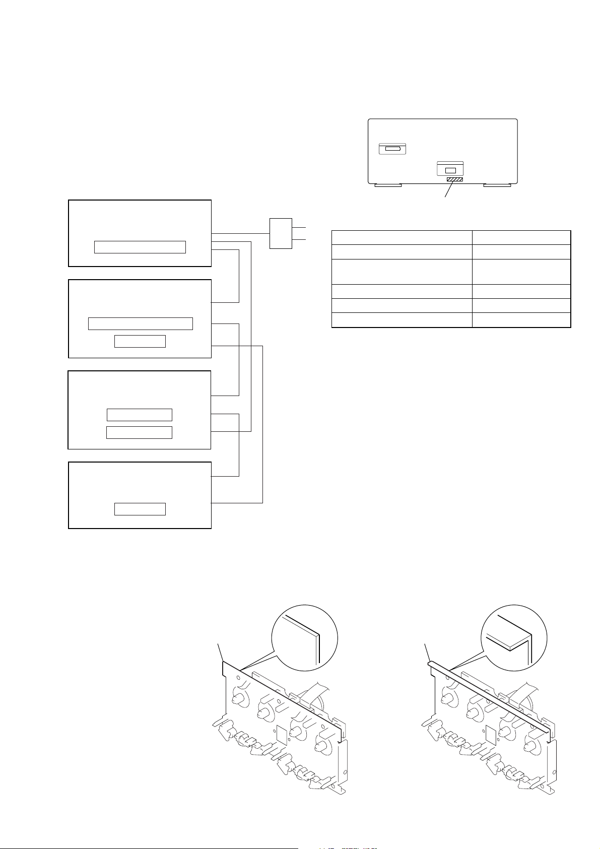
This set is a component of the MHC-S9D.
The MHC-S9D system configuration is as shown belo w , and therefore it does not operate normally unless all four components are
connected.
In performing the repair, connect all components with the system
cables.
Note: The precaution to the users is described on the label stuck
on the back panel (DVD/video CD/CD player) and in the troubleshooting section in the Operation Manual.
System Configuration:
AC IN
TA
POWER SUPPLY
ST
MASTER & GRAPHIC µcon
DISPLAY
• MODEL IDENTIFICATION
– Rear Panel –
PART No.
Model PART No.
AEP and UK models 4-236-839-0
Australian, Saudi Arabia
and Korean models
E and Singapore models 4-236-839-2[]
Mexican model 4-236-839-3
Thai model 4-236-839-4
4-236-839-1[]
[]
[]
[]
DVP
HTC & MB µcon
POWER BLOCK
TC
TC µcon
main chassis
• TAPE MECHANISM DECK DISCRIMINATION
TCM-230AWR41 and TCM-230MWR41 are used for the tape
mechanism deck of this set, and they can be discriminated as shown
below.
straight L-shape
main chassis
TCM-230AWR41 TCM-230MWR41
3
TC-S9
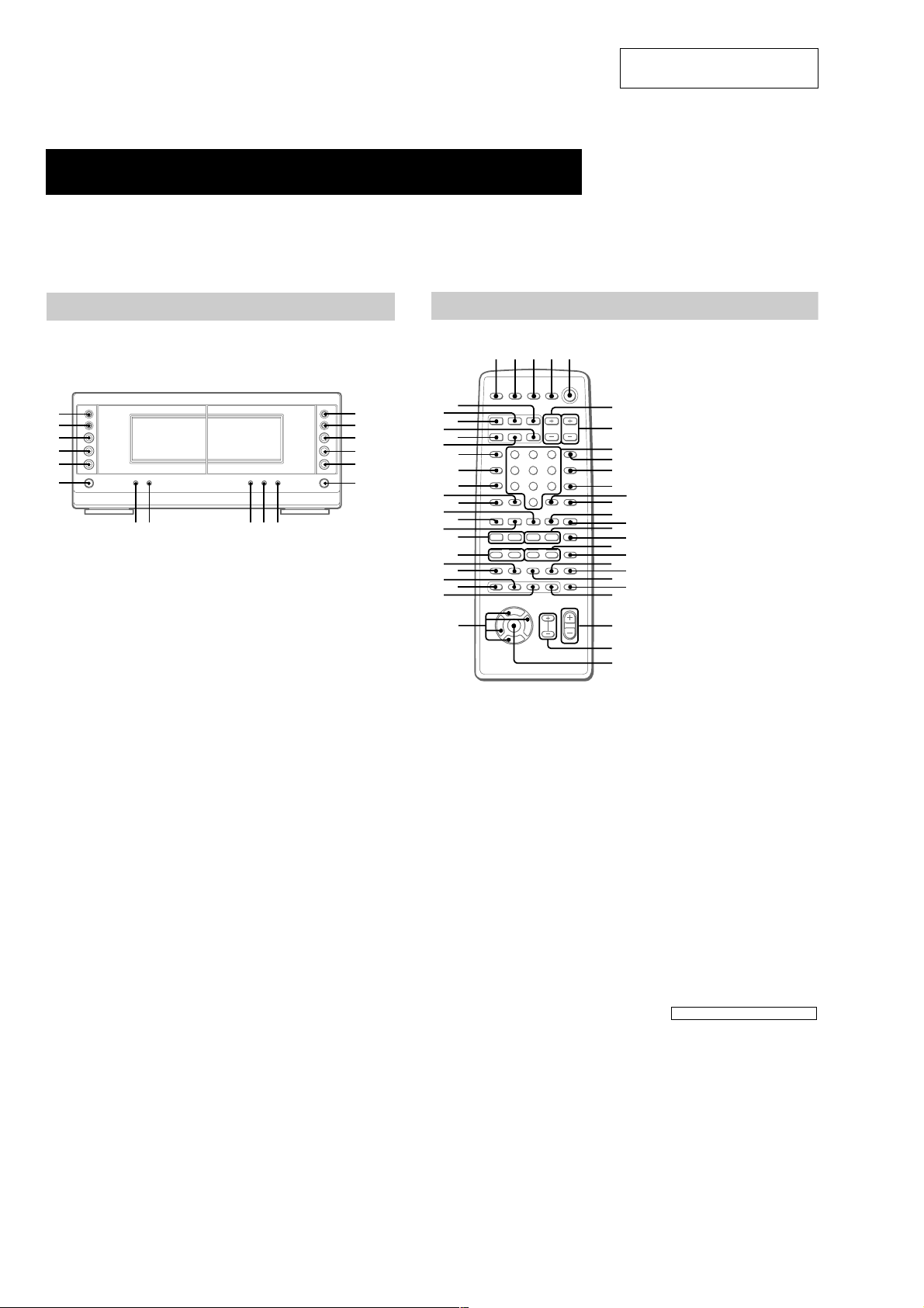
LOCATION OF CONTROLS
Parts Identification
The items are arranged in alphabetical order.
Refer to the pages indicated in parentheses ( ) for details.
SECTION 2
GENERAL
This section is extracted from
instruction manual.
Main unit
Cassette deck
y;
.
tl
tk
h
tj
th
A A
tg
CD SYNC ta (45, 46)
DIRECTION tf (44, 45, 46, 55)
DOLBY NR td (44–46)
HI-DUB ts (45)
REC PAUSE/START t; (45, 46, 55)
– Deck A –
N (forward play) tk (44, 55, 63)
n (reverse play) tj (44, 63)
x (stop) th (44)
>/M (go forward/fast
forward) y; (44)
./m (go back/rewind) tl
(44)
Z (eject) tg (44, 63)
AUTO REVERSE
hH
AUTO REVERSE
hH
– Deck B –
N (forward play) rh (44, 45, 63)
n (reverse play) rj (44, 45, 63)
x (stop) rk (44, 45, 55)
M/> (fast forward/go
forward) rf (44)
m/. (rewind/go back) rg
(44)
Z (eject) rl (44, 63)
Remote control
123 4 5
rf
.
rg
H
rh
h
rj
x
rk
rl
t;tatstdtf
rk
rh
rf
r;
ek
eh
ed
ea
wl
rl
rj
rg
rd
rs
ra
el
ej
eg
ef
es
e;
wk
O
V
Bb
v
nN
Mm>.
TtCc
6
7
8
9
q;
qa
qd
qf
qh
qk
w;
ws
wf
wg
wh
wj
ANGLE es (37)
AUDIO ws (34)
CLEAR qs (22, 29, 30, 36)
CLOCK/TIMER SELECT 3
(47, 56)
CLOCK/TIMER SET 2 (17, 47,
56)
DBFB ra (48)
D.SKIP 9 (26)
DIGITAL rf (57)
DISPLAY rj (17, 31, 32, 43, 54)
DVD DISPLAY wd (18, 19, 30,
qs
qg
qj
ql
wa
wd
32–34, 36–40)
DVD MENU wa (27)
DVD SET UP ql (18, 19, 24, 39)
ENTER wj
EQ ea (52)
EQ ON/OFF wl (53)
FILE SELECT +/– wh (48, 49,
53)
FUNCTION rd (18, 25, 27, 28,
36, 45, 46, 55, 57)
GROOVE rs (48)
KARAOKE PON (Except for
European
MD rh (57)
Numeric buttons 8 (28, 30)
PLAY MODE qa (25, 28, 29, 46)
REPEAT q; (30)
RETURN O qd (27, 39, 40)
SELECT DVD N eh (20, 25,
27, 29, 30)
SET UP wf (14, 16, 51, 53, 54)
SLEEP 1 (55)
SLOW t/T qk (26)
SPECTRUM ANALYZER rk
(54)
STEP c/C ef (26)
SUBTITLE ed (37)
SUR e; (51)
TAPE A nN ek (44)
TAPE B nN qf (44, 45)
TITLE w; (27)
TUNER/BAND ej (42)
TV @/1 4 (13)
TV CH +/– 7 (13)
TV/VIDEO rl (13)
TV VOL +/– 6 (13)
VIDEO rg (57)
VOL +/– wg
model) el (54)
BUTTON DESCRIPTIONS
@/1 (power) 5
X (pause) qj
x (stop) qg
m/M (rewind/fast forward),
TUNING –/+ qh
./> (go back/go forward),
PRESET –/+, PREV/NEXT eg
O/o/P/p wk
>10 r;
4
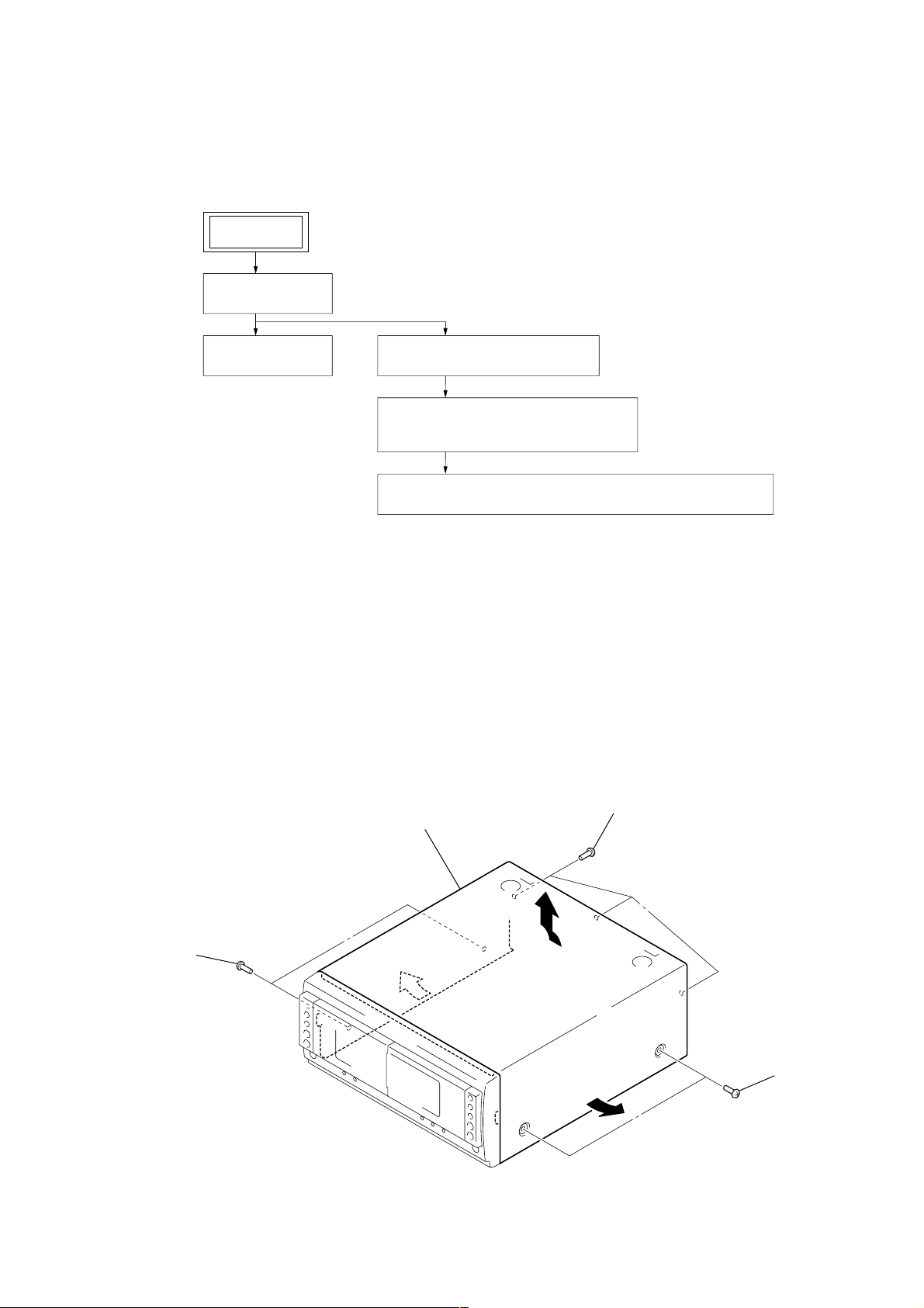
• This set can be disassembled in the order shown below.
2
two screws
(case 3 TP2)
3
3
2
two screws
(case 3 TP2)
1
three screws
(BVTT3
×
6)
4
Remove the case in the
direction of arrow
A
.
A
3-1. DISASSEMBLY FLOW
SET
3-2. CASE
(Page 5)
TC-S9
SECTION 3
DISASSEMBLY
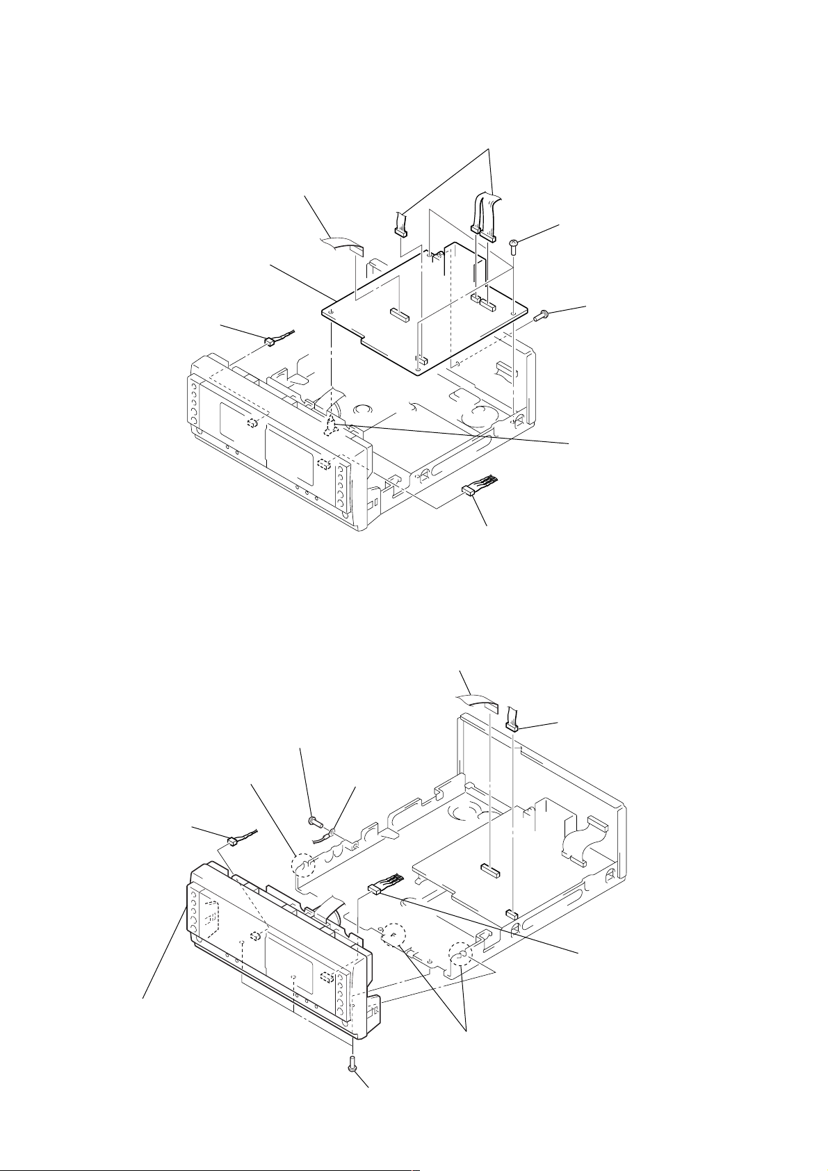
3-3. MAIN BOARD
(Page 6)
Note: Follow the disassembly procedure in the numerical order given.
3-4. FRONT PANEL SECTION
(Page 6)
3-5. TAPE MECHANISM DECK
(TCM-230AWR41, TCM-230MWR41)
(Page 7)
3-6. LEAF SW BOARD, HEAD (A) BOARD AND HEAD (B) BOARD
(Page 7)
3-2. CASE
5
TC-S9
3-3. MAIN BOARD
2
5
connector
(CN1)
1
wire (flat type) (17 core)
(CN311)
MAIN board
2
three connectors
(CN309, 310, 314)
3
three screws
(BVTP3
3
×
8)
screw
(BVTP3
×
8)
3-4. FRONT PANEL SECTION
6
two claws
2
connector
(CN1)
3
screw
(BVTP3
4
PC board holder
2
connector
(CN2)
1
wire (flat type) (17 core)
(CN311)
2
connector
×
8)
4
lug
(CN314)
2
connector
(CN2)
7
front panel section
6
three claws
5
three screws
(BVTP3
×
8)
6
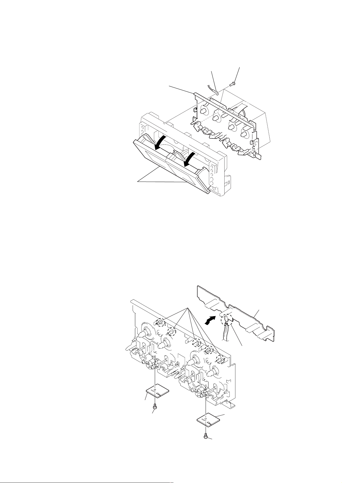
3-5. TAPE MECHANISM DECK (TCM-230AWR41, TCM-230MWR41)
)
3
lug
4
tape mechanism deck
(TCM-230AWR41, TCM-230MWR41)
1
Open the
cassette holder (L)/(R).
2
five screws
(BVTP2.6
TC-S9
×
8
3-6. LEAF SW BOARD, HEAD (A) BOARD AND HEAD (B) BOARD
2
five claws
5
head (A) board
4
screw (+PTT 2
×
4)
7
3
LEAF
1
Remove the four solderings.
head (B) board
SW board
6
screw (+PTT 2
×
4)
7

TC-S9
SECTION 4
TEST MODE
Note: Use following buttons in the test mode.
no mark: Button of Tape unit (TC-S9)
*1 : Button of amplifier unit (TA-S9D)
*2 : Button of DVD/video CD/CD unit (DVP-S9)
[MC Test Mode]
Enter the MC Test Mode
Procedure:
1. Press the I/1 *1 button to turn the power on.
2. While pressing the both [PLAY MODE]*2 and [ ]*2 buttons,
press the [DISC 3]*2 button.
3. “GROOVE” indication blinks on the fluorescent indicator tube
in the midst of MC test mode.
Releasing the MC Test Mode
To release from this mode, press the I/1 *1 button or disconnect
the power cord.
x
[DECK Test Mode]
In the DECK test mode, it operates as follows.
Cancellation of the linear mute of DOLBY IC (IC301)
• It become cancellation automatically when it is possible to en-
ter a MC test mode.
AMS Checking
Procedure:
1. Enter the MC test mode.
2. Insert a test tape AMS-110A or AMS-120 to Deck A.
3. Set TAPE A function.
4. Press the [DVD SYNC] button to enter the AMS test mode.
5. After a tape is rewound first, the FF AMS is checked, and the
mechanism is shut off after detecting the ASM signal twice.
6. Then the REW AMS is checked and the mechanism is shut of f
after detecting the AMS signal twice.
7. When the check is complete, a message of either OK or NG
appears.
(To check an AMS of the B deck, select TAPE B function.
After that, press
[DVD SYNC].)
ALC Checking
Procedure:
1. Enter the MC test mode.
2. Insert a tape into Deck B.
3. During Recording, Keep holding down the below keys.
Double Speed REC Mode
Procedure:
1. Enter the MC test mode
2. Insert a tape into Deck B.
3. During Recording, keep holding down the below key.
2
[ ]*
+ [REC PAUSE/START]
x
ALC could keep ON while these keys keep being pressed, ALC
could keep OFF while keys are released.
[HI-DUB]
Double speed recording is going on while the key keeps being
pressed.
REC/PLAY Checking
• The mode to PLAY by rewinding recording contents automatically.
Procedure:
1. If recording A surface, it returns automatically at the point of
the recording beginning and it replays when pressing
TAPE B [ ].
2. If recording B surface, it returns automatically at the point of
the recording beginning and it replays when pressing
TAPE B [ ].
M
m
8
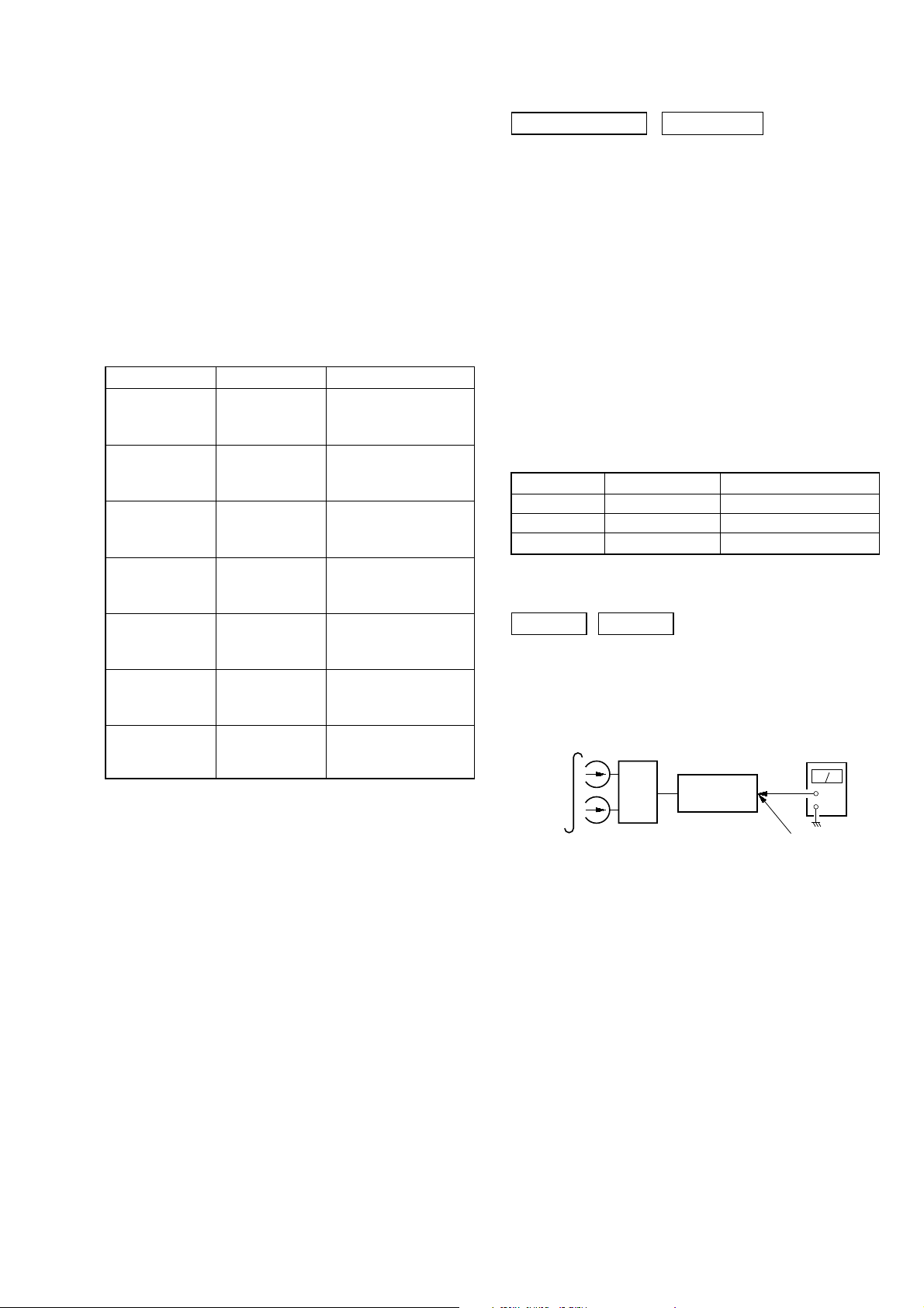
SECTION 5
set
ST-S9
test tape
P-4-A100
(10 kHz, –10 dB)
+
–
level meter
MD OUT jack
(J601)
MECHANICAL ADJUSTMENTS
TC-S9
SECTION 6
ELECTRICAL ADJUSTMENTS
Precaution
1. Clean the following parts with a denatured alcohol-moistened
swab:
record/playback heads pinch rollers
erase head rubber belts
capstan idlers
2. Demagnetize the record/playback head with a head demagnetizer.
3. Do not use a magnetized screwdriver for the adjustments.
4. After the adjustments, apply suitable locking compound to the
parts adjusted.
5. The adjustments should be performed with the rated power
supply voltage unless otherwise noted.
Torque Measurement
Mode Torque meter
FWD
FWD
back tension
REV
REV
back tension
FF/REW
FWD tension
REV tension
CQ-102C
CQ-102C
CQ-102RC
CQ-102RC
CQ-201B
CQ-403A
CQ-403R
Meter reading
3.06 N • m to 6.96 N • m
31 to 71 g • cm
(0.43 – 0.98 oz • inch)
0.19 N • m to 0.58 N • m
2 to 6 g • cm
(0.02 – 0.08 oz • inch)
3.06 N • m to 6.96 N • m
31 to 71 g • cm
(0.43 – 0.98 oz • inch)
0.19 N • m to 0.58 N • m
2 to 6 g • cm
(0.02 – 0.08 oz • inch)
6.96 N • m to 14.02 N • m
71 to 143 g • cm
(0.98 – 1.99 oz • inch)
9.80 N • m
100 g or more
(3.53 oz or more)
9.80 N • m
100 g or more
(3.53 oz or more)
0 dB=0.775 VDECK SECTION
1. Demagnetize the record/playback head with a head
demagnetizer.
2. Do not use a magnetized screwdriver for the adjustments.
3. After the adjustments, apply suitable locking compound to the
parts adjust.
4. The adjustments should be performed with the rated power
supply voltage unless otherwise noted.
5. The adjustments should be performed in the order given in
this service manual. (As a general rule, playback circuit adjustment should be completed before performing recording
circuit adjustment.)
6. The adjustments should be performed for both L-CH and RCH.
7. Switches and controls should be set as follows unless otherwise specified.
8. Please refer to “SERVICING NO TES” (page 3) before adjustments.
• T est Tape
Tape Signal Used for
P-4-A100 10 kHz, –10 dB Azimuth Adjustment
WS-48B 3 kHz, 0 dB Tape Speed Adjustment
P-4-L300J 315 Hz, 0 dB Level Adjustment
Record/Playback Head Azimuth Adjustment
DECK A DECK B
Note: Perform this adjustments for both decks
Procedure:
1. Mode: Playback
9
 Loading...