

Page 1
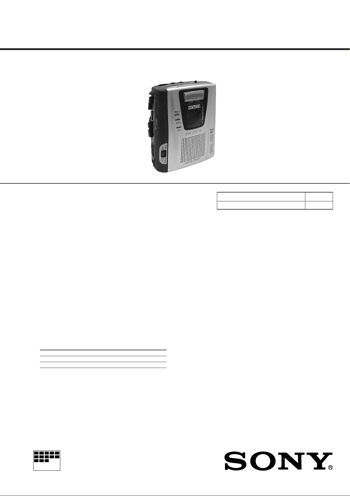
TCM-50DV
SERVICE MANUAL
Ver 1.0 1999. 02
SPECIFICATIONS
US Model
Canadian Model
AEP Model
E Model
Tourist Model
Model Name Using Similar Mechanism NEW
Tape Transport Mechanism Type MT-50-30
Recording system
2-track 1 channel monaural
Tape speed
4.8 cm/s or 2.4 cm/s
Frequency range
250 - 6,300 Hz using normal (TYPE I) cassette (with REC TIME switch
at “NORMAL”)
Speaker
Approx. 3.6 cm (1 7/16 in.) dia.
Power output
250 mW (at 10% harmonic distortion)
Input
Microphone input jack (minijack) sensitivity 0.2 mV for 3 kilohms or
lower impedance microphone
Output
Earphone jack (minijack) for 8 - 300 ohms earphone
Variable range of the tape speed
From approx. +25% to –15% (with REC TIME switch at “NORMAL”)
Power requirements
3 V DC batteries AA (R6) × 2/External DC 3 V power sources
Battery life (Approx. hours) (EIAJ*)
Sony alkaline LR6 (SG) Sony R6P (SR)
Playback 9.5 1.5
Recording 10.5 2
* Measured value by the standard of EIAJ (Electronic Industries
Association of Japan). (Using a Sony HF series cassette tape)
Dimensions (w/h/d) (inci. projecting parts and controls)
Approx. 88.7 × 115.3 × 37.2 mm (3 1/2 × 4 5/8 × 1 1/2 in.)
Mass
Approx. 250 g (8.9 oz.)
Supplied accessories
Size AA (R6) batteries (2) (Tourist model only)
Earphone (1) (Tourist model only)
Design and specifications are subject to change without notice.
MICROFILM
CASSETTE-CORDER
– 1 –
Page 2

TABLE OF CONTENTS
1. SERVICING NOTE ..................................................... 3
2. GENERAL
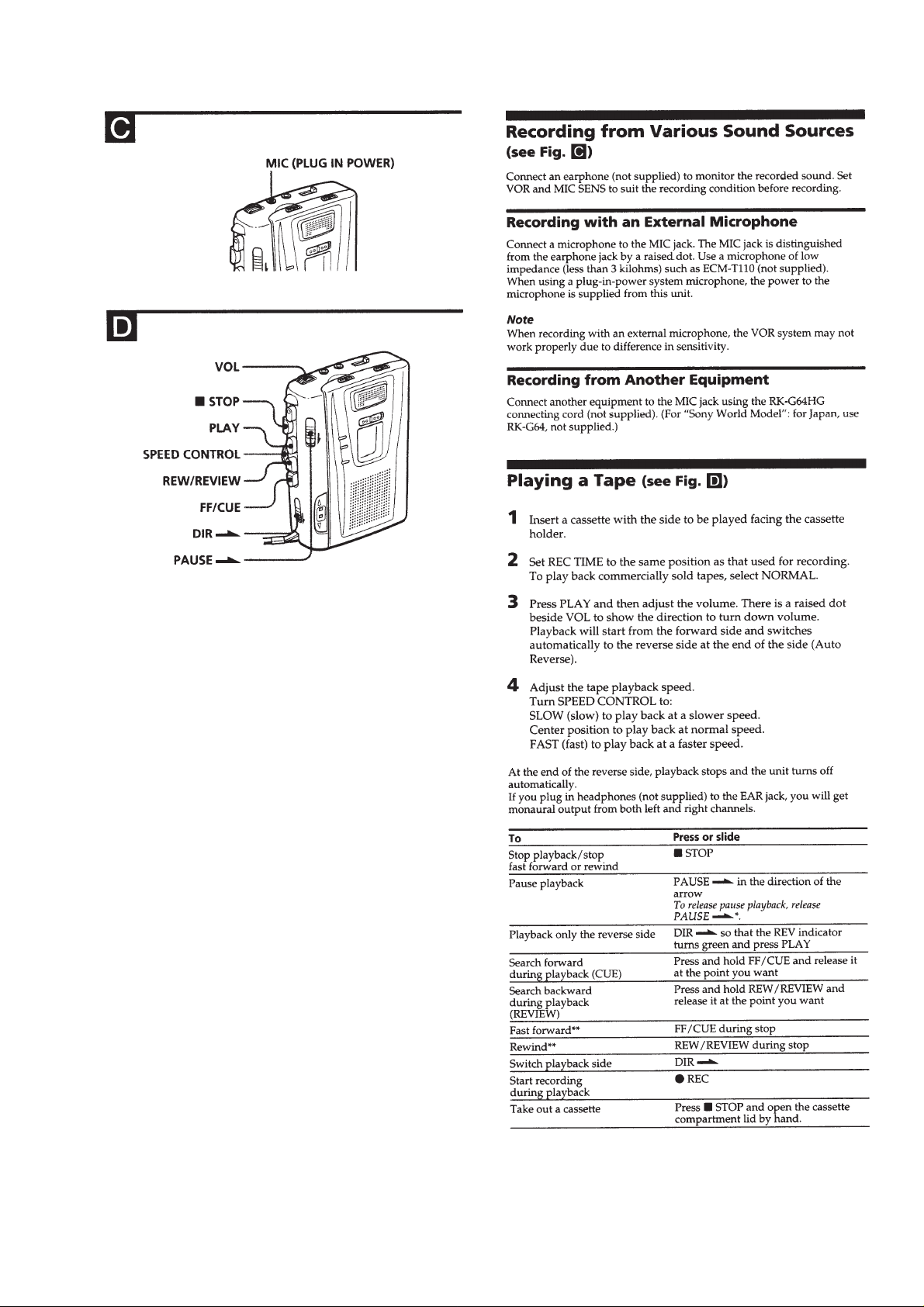
Operating the Unit ................................................................... 4
3. DISASSEMBLY
3-1. Cabinet, Cassette Lid Assy ................................................. 6
3-2. MAIN Board, Cassette Machanism .................................... 7
3-3. Belt ...................................................................................... 8
3-4. Head .................................................................................... 8
3-5. Motor, DC ........................................................................... 9
3-6. Note for Installation of Main Board.................................... 9
4. MECHANICAL ADJUSTMENTS............................ 10
5. ELECTRICAL ADJUSTMENTS .............................10
6. DIAGRAMS
6-1. Block Diagram .................................................................. 11
6-2. Printed Wiring Board –Main Section– .............................. 13
6-3. Schematic Diagram –Main Section–.................................15
6-4. Printed Wiring Board –Panel Section– ............................. 17
6-5. Schematic Diagram –Panel Section– ................................ 18
6-6. IC Pin Description............................................................. 20
7. EXPLODED VIEWS
7-1. Case Section ...................................................................... 21
7-2. Panel Section..................................................................... 22
7-3. Mechanism Deck Section-1 .............................................. 23
7-4. Mechanism Deck Section-2 .............................................. 24
8. ELECTRICAL PARTS LIST ....................................25
Notes on Chip Component Replacement
• Never reuse a disconnected chip component.
• Notice that the minus side of a tantalum capacitor may be dam-
aged by heat.
Flexible Circuit Board Repairing
• Keep the temperature of the soldering iron around 270˚C during
repairing.
• Do not touch the soldering iron on the same conductor of the
circuit board (within 3 times).
• Be careful not to apply force on the conductor when soldering
or unsoldering.
– 2 –
Page 3

SECTION 1
SERVICING NOTE
1-1. SERVICE MODE
Mode to allow the mechanical parts to operate with the main board
open.
This set uses the photo reflector PH701 to detect the rotation of the
idler gear. PH701 is on the main board and so remo val of the main
board does not allow the set to detect the rotation of the idler gear.
This makes motor control impossible which prevents normal
operation.
When repairing the set as energized with the main board removed,
proceed as follows:
1. Setting
1) Remove the cabinet (rear) (refer to the Disassembly) and open
the main board.
2) Apply a trapezoidal of 10 to 100 Hz (at 1.3 V) from oscillator to
TP20. (Connect the ground to TP30.)
3) Supply DC 3.0 V to the positive and negative terminals of the
battery with a stabilized power supply.
2. FF mode
1) Apply a trapezoidal to hall sensor TP20.
2) Press the FF key.
3) Turn on the S103 (POWER) switch.
3. REW mode
1) Apply a trapezoidal to hall sensor TP20.
2) Press the REW key.
3) Turn on the S103 (POWER) switch.
– main board (conductor side) –
TP20
– main board (component side) –
TP30
TP20
TP30
4. PLAY mode
1) Apply a trapezoidal to hall sensor TP20.
2) Press the PLAY key.
3) Change over the S101 (REC/PB) switch to PB side.
4) Turn on the S103 (POWER) switch.
5. REC mode
1) Apply a trapezoidal to hall sensor TP20.
2) Press the REC key.
3) Change over the S101 (REC/PB) switch to REC side.
4) Turn on the S103 (POWER) switch.
S103
(POWER)
S101
PB REC
– 3 –
Page 4
SECTION 2
GENERAL
This section is extracted
from instruction manual.
– 4 –
Page 5
– 5 –
Page 6
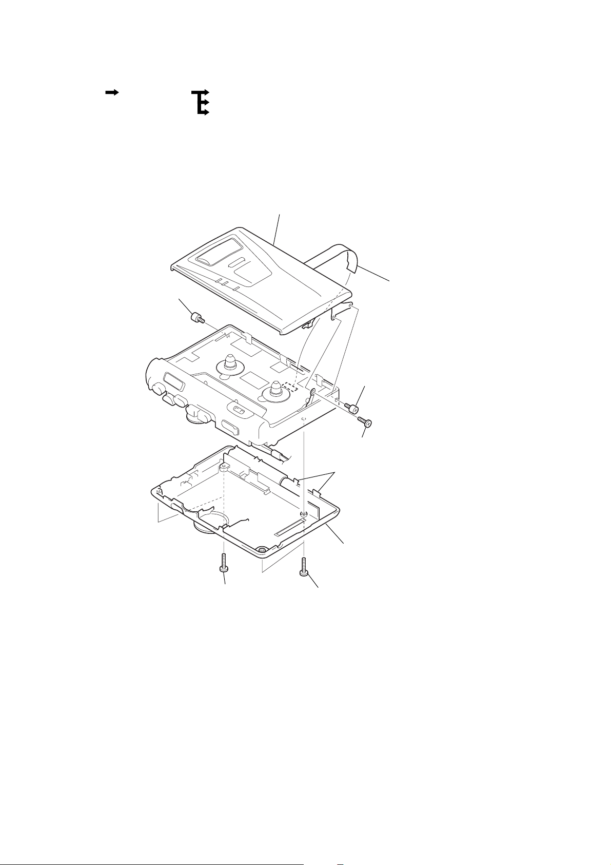
SECTION 3
d
DISASSEMBLY
• The equipment can be removed using the following procedure.
Cabinet (rear),
Cassette Lid Assy
Note : Follow the disassembly procedure in the numerical order given.
3-1. CABINET (REAR), CASSETTE LID ASSY
Mechanism Deck,
Main board
8
screw, ornamental
Belts
Head
Motor, DC
9
cassette lid assy
5
LED flexible boar
2
two screws
(screw (B1.7x9), tapping)
7
screw, ornamental
6
shaft (A), stopper
3
two claws
4
cabinet (rear)
1
two screws
(screw (B1.7x9), tapping)
– 6 –
Page 7
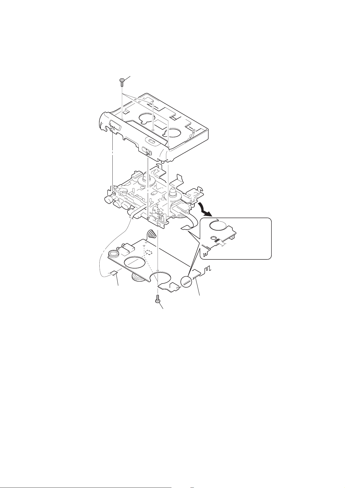
3-2. MACHANISM DECK, MAIN BOARD
1
three screws
(screw (IB lock))
2
mechanism deck,
MAIN board
4
head flexible board
6
MAIN board
5
two screws
(screw (M1.4), toothed lock)
3
Remove the four solders.
– 7 –
Page 8
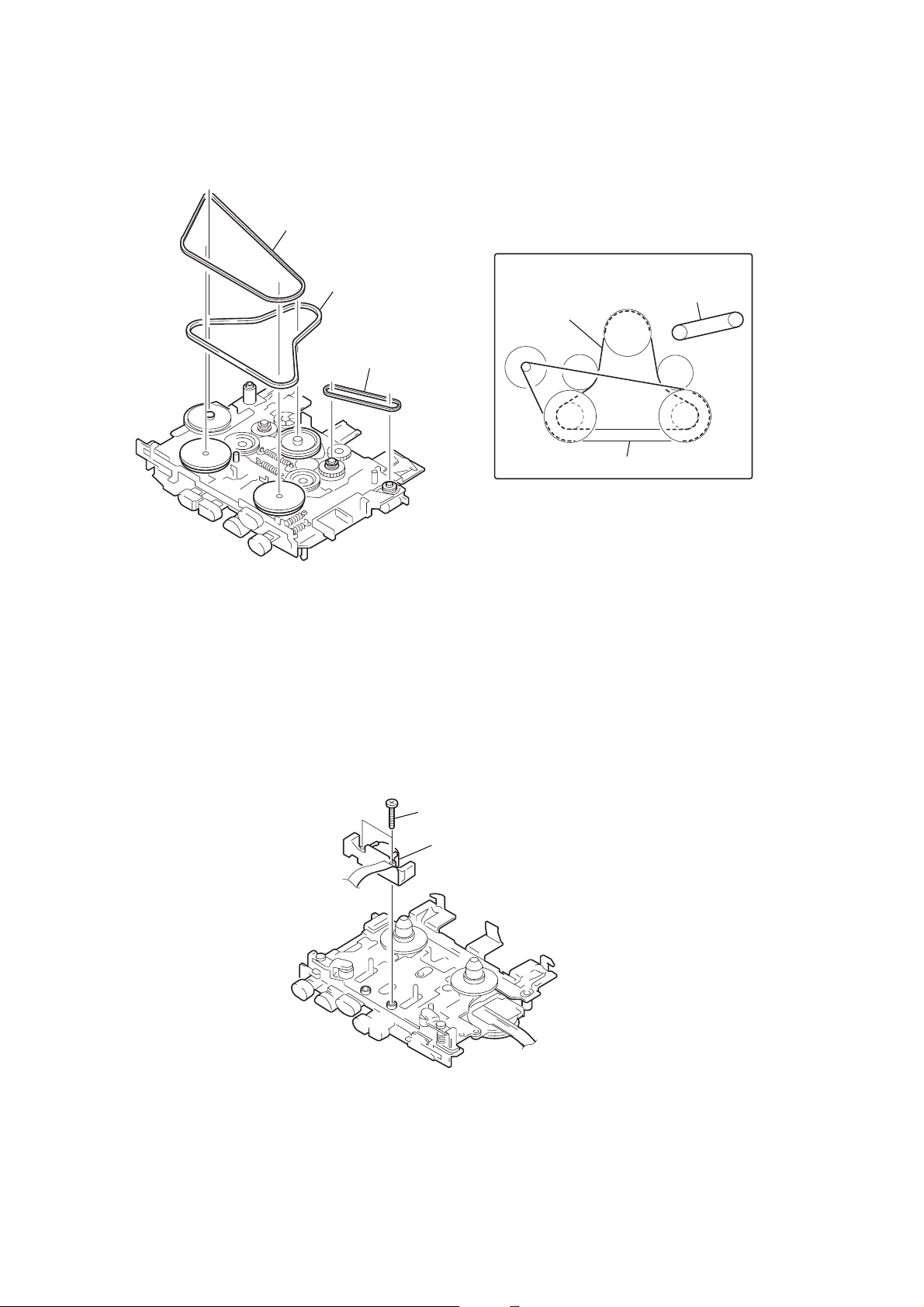
3-3. BELTS
1
belt (motor)
2
belt (flywheel)
3
belt (counter)
• How to apply the belts
belt (counter)
belt (flywheel)
belt (motor)
3-4. HEAD
1
two screws
2
head, magnetic
(REC/PB/ERASE)
– 8 –
Page 9

3-5. MOTOR, DC
2
screw (1.4)
3
Remove the four solders.
1
screw (1.4)
4
Motor, DC
3-6. NOTE FOR INSTALLATION OF MAIN BOARD
Align the knobs of S101, S103 and S701 on the main board with the
claws of the lever (REC) le ver (erase proof 2) and lever (REC) of the
mechanism deck respectively, and install the main board.
screws (M1.4), toothed lock
MAIN board
S701
S103
S101
lever (erase proof 2)
mechanism deck
lever (REC)
lever (PAUSE)
– 9 –
Page 10

r
SECTION 4
MECHANICAL ADJUSTMENTS
PRECAUTION
1. Clean the following parts with a denatured-alcohol-moistened
swab :
record/playback/erase head pinch roller
capstan rubber belt
2. Demagnetize the record/playback/erase head with a head
demagnetizer. (Do not bring the head demagnetizer close to the
erase head.)
3. Do not use a magnetized screwdriver for the adjustments.
4. After the adjustments, apply suitable locking compound to the
parts adjusted.
5. The adjustments should be performed with the rated power
supply voltage (1.3 V) unless otherwise noted.
Torque Measurement
Mode Torque Meter Meter Reading
FWD
FWD less than 2 g • cm
back tension (less than 0.03 oz • inch)
REV
REV less than 2 g • cm
back tension (less than 0.03 oz • inch)
FF, REW CQ-201B
CQ-102C
CQ-102RC
15 – 25 g • cm
(0.21 – 0.35 oz • inch)
15 – 25 g • cm
(0.21 – 0.35 oz • inch)
more than 50 g • cm
(more than 0.69 oz • inch)
Tape Speed Adjustment
Procedure :
test tape
WS-48A
(3 kHz, 0 dB)
set
EAR jack
1. REC TIME : NORMAL/FWD ·
Playback WS-48A (tape center part) and adjust RV601 so that
reading on the digital frequency counter becomes 3,000 Hz.
2. REC TIME : DOUBLE/FWD ·
Playback WS-48A (tape center part) and adjust RV602 so that
reading on the digital frequency counter becomes 1,500 Hz.
Specification Value :
Digital Frequency Counter Reading
REC TIME : NORMAL REC TIME : DOUBLE
2,985 to 3,015 Hz 1,485 to 1,515 Hz
3. REC TIME : NORMAL/REV ª
Playback WS-48A (tape center part) and confirm that the
reading on digital frequency counter are between 2,985 to 3,015
Hz.
digital
frequency counte
Ω
8
SECTION 5
ELECTRICAL ADJUSTMENTS
PRECAUTION
• Supplied voltage : DC 3.0 V
• Switch and control position
VOL control : max (10)
MIC SENS switch : free (L or H)
V•O•R switch : free (OFF or ON)
SPEED CONTROL control : mechanical center
Test T ape
Type Signal Used for
WS-48A 3 kHz, 0 dB tape speed adjustment
4. REC TIME : DOUBLE/REV ª
Playback WS-48A (tape center part) and confirm that the
reading on digital frequency counter are between 1,435 to 1,515
Hz.
Adjustment Location :
–main board (conductor side)–
RV602
RV601
– 10 –
Page 11

6-1. BLOCK DIAGRAM
TCM-50DV
SECTION 6
DIAGRAMS
HRPE901
REC/PB/ERASE HEAD
REC/PB
(FWD)
REC/PB
(REV)
ERASE
(FWD)
ERASE
(REV)
MIC901
Flat Mic
J102
MIC
S102-4
(FWD/REV)
S102-3
(FWD/REV)
FWD
REV
FWD
REV
T101
BIAS OSC
NORMAL
DOUBLE
Q112
S903-1
REC TIME
V O R
ON
OFF
S901
Q106
Q111
+3V
PB
REC
S101-1
(REC/PB)
S902
MIC SENS
L
7
5
6
NF LEVEL
SWITCH
H
OUT1
RECOVERY
TIME CAP
OUT2
Q105
VOR
IC501
NF LEVEL
SWITCH
Q103
PRE / POWER AMP
IC101
EQ IN
29
VREF OUT
27
4
REC OUT
1
IN
SWITCH
Q501
PRE NF
1
NF LEVEL
SWITCH
Q101
Q104
LED CONTROL
Q302,303
28
5
MIC IN
ALC CONT
+
-
+
-
+
PRE
OUT
REC
IN
RV101
2
3
VOL
D903
LED
CONTROL
Q301
MUTE
Q109
MUTE
DRIVE
Q110
AMP
Q102
SWITCH
Q107,108
4
BATTERY
VOLTAGE
DETECTOR
IC301
OUT
S101-2
(REC/PB)
PB
REC
POW
21
23
26
25
IN
R/P MUTE
R/P SW
MIC VCC
R.F OUT
POW
OUT1
1
12
POW
OUT2
2
14
R.F
(REC/PB)
PB
REC
S101-3
+3V
+3V
SP101
SPEAKER
J101
EAR
S103
(POWER)
CN101
DC IN 3V
+
-
DRY BATTERY
SIZE "AA"
(IEC DESIGNATION R6)
2PCS,3V
• Signal path
: TAPE (PB)
: TAPE (REC)
S702
(REW / REVIEW)
S703
(DIR)
S704
(FF / CUE)
04
+3V
IN2
5
IN3
6
8
IN5
TAPE ROTATION DETECTOR
S701
PAUSE
OFF ON
IN7
10
PULSE
AMP
Q708
PH701
Q701
+3V
D901
BATT
D902
D702
4
IN1
CL
3
VCC
24
SWITCH
Q706, 707
DP CON
OSC
Q702
T701
23
CONT
22
D701
REC
SYSTEM CONTROL
IC702
VDD
V OUT V IN
3
IC701
LED CONTROL
REG
Q704
+3V
18
OUT5
IN6
(FWD /REV)
REV FWD
OUT4
S102-2
19
OUT3
IN8
OUT2
OUT1
20
21
MOTOR
CONTROL
Q705
17
IN4
7119 11
SWITCH
Q703
+3V
2
19
11
S903-2
REC TIME
DIR
S/S
DOUBLE
NORMAL
DIRECTION
BIAS
REF VOLTAGE
FOR SPEED CONTROL
REF
VOLTAGE
VREF
12
PULSE
DET
OSC
CURRENT
RV601
TAPE SPEED
REC TIME NORMAL
RV602
TAPE SPEED
REC TIME DOUBLE
OPERATION
DET
LOGIC
MOTOR SERVO
IC601
DRIVER
FREQ.
CHARC.
S101-4
(REC/PB)
PB
REC
PRE
ERROR
AMP
IN +
13
U OUT
V OUT
W OUT
RV603
SPEED CONTROL
20
1
2
MOTOR
BRAKE SW
Q601 - 604
M901
CAPSTAN/REEL
MOTOR
– 11 – – 12 –
Page 12

TCM-50DV
6-2. PRINTED WIRING BOARD — MAIN SECTION —
A
B
C
D
1
S702
(REW/REVIEW)
234567891011121314
S703
(DIR)
TP20
TP30
E
F
G
H
J
I
04
Note on Printed Wiring Boards:
• X : parts extracted from the component side.
®
•
• b : Pattern from the side which enables seeing.
: Through hole.
(FF/CUE)
SPEED CONTROL
1-672-148- (11)
11
S701
ON
OFF
S101
(REC/PB)
PB REC
REV FWD
S102 (FWD/REV)
11
1-672-148- (11)
DRY BATTERY
SIZE " AA "
(IEC DESIGNATION R6)
2PCS,3V
• Semiconductor Location
Ref. No. Location
D701 C-1
D702 D-2
IC101 F-9
IC301 F-10
IC501 E-2
IC601 C-8
IC701 C-1
IC702 C-2
PH701 D-1
Q101 H-10
Q102 D-9
(Page 17)
HRPE901
REC/PB/ERASE
HEAD
REC/PB
( )
ERASE
( )
REC/PB
( )
ERASE
( )
Ref. No. Location Ref. No. Location
Q103 D-9
Q104 D-9
Q105 E-10
Q106 H-2
Q107 F-8
Q108 F-8
Q109 F-9
Q110 F-8
Q111 F-1
Q112 G-3
Q301 F-10
Q302 F-10
Q303 F-10
Q501 E-2
Q601 B-10
Q602 B-10
Q603 B-9
Q604 B-9
Q701 D-2
Q702 D-1
Q703 D-2
Q704 D-9
Q705 C-2
Q706 B-2
Q707 B-2
Q708 D-1
– 13 – – 14 –
Page 13

6-3. SCHEMATIC DIAGRAM — MAIN SECTION — • Refer to page 19 for IC Block Diagrams.
TCM-50DV
(Page 18)
Note on Schematic Diagram:
• All resistors are in Ω and 1/
specified.
• C : panel designation.
• U : B+ Line.
• H : adjustment for repair.
• Power voltage is dc 3 V and fed with regulated dc power
supply from external power voltage jack.
• Voltage is dc with respect to ground under no-signal
(detuned) condition.
4
W or less unless otherwise
– 15 – – 16 –
no mark : PB
( ) : REC
[ ] : FF/REW
• Voltages are taken with a VOM (Input impedance 10 MΩ).
Voltage variations may be noted due to normal production tolerances.
• Signal path.
E : PB
a : REC
Page 14

TCM-50DV
6-5. SCHEMATIC DIAGRAM — PANEL SECTION —6-4. PRINTED WIRING BOARD — PANEL SECTION —
A
B
C
D
1
23456
11
1-672-149-
(11)
(Page 15)
E
F
G
H
Note on Printed Wiring Boards:
• X : parts extracted from the component side.
®
•
• b : Pattern from the side which enables seeing.
S902
H L
S903
DOUBLE NORMAL
I
S901
ON OFF
04
18
: Through hole.
1-672-149-
Note on Schematic Diagram:
• All resistors are in Ω and 1/
specified.
• C : panel designation.
• Signal path.
E : PB
11
(11)
1
4
W or less unless otherwise
J
1
LED
FLEXIBLE
BOARD
(Page 14)
– 17 – – 18 –
Page 15

• IC Block Diagrams
IC101 LA4168ML
PRE GND
EQ IN
MIC IN
Vref OUT
MIC VCC
R, F OUT
LED DRIVE
R/P SW
PAUSE
P/R MUTE
21222324252627282930
GVN CONT
GVN Vref
Vs
GVN GND
GVN OUT
181920
17
16
1
PRE NF
300k
SPEED
8
GNV SPEED UP
PAUSE
MIC
VCC
+
–
Vref
9
AUT STOP CONT
10
AUT STOP IN
11
PWR IN
1
12
PWR OUT1
R/P
R, F
POWER
13
PWR GND
2
14
PWR OUT2
GVN
15
Vcc
2.2k
30k
2k
+
–
EQ
2
PRE OUT
+
3
REG IN
+
4
–
20k
REC
REG OUT
5
ALC CONT
ALC
6
VOX CONT
VOX
VOX
7
VOX DELAY
–
MIC
IC601 LB1877V
1
VOUT
2
WOUT
PGND
3
4
WB
VB
5
UB
6
OSC
7
OSC
COM
GND
START
8
DET
9
FEED
10
RI
BACK
PRE DRIVER
OPERATION LOGIC
PULSE DET
DIRECTION
ANTI
LOCKING
CURRENT
DET
TSD
FREQ.
CHARC.
ERROR
–
AMP
SLEEP
DET
REF VOLTAGE
FOR SPEED CONTROL
REF
VOLTAGE
BIAS
IC501 NJM2072M
20
UOUT
19
DR
18
VCC
LB
17
16
FC
OUT
15
VSP
14
+
IN+
13
VREF
12
S/S
11
INPUT
GAIN CONT
AMP OUT
GND
1
2
3
4
IC301 MM1251M
NC
VCC
VS
7
8
6
–
+
+
VREF
1
2
CT
NC
VOLTAGE UP
–
CIRCUIT
3
GND
5
HYS
VCC
8
OUTPUT2
7
OUTPUT1
6
RECOVERY
5
TIME CAP
4
OUT
– 19 –
Page 16

6-6. IC PIN DESCRIPTION
• IC702 TB2004FN-020 (SYSTEM CONTROL)
Pin No. Pin Name I/O Pin Description
1 GND — GND
2 OSC — For system clock generation (fosc=3.2 kHz)
3 CL I RESET input
4 IN1 I Pause ON/OFF by PAUSE SW and VOR. “L” : ON, “H” : OFF
5 IN2 I FWD reset by cassette cover open-close. “L” : ON, “H” : OFF
6 IN3 I Direction “L” : ON, “H” : OFF
7 IN4 I REC/PB switch “L” : REC, “H” : PB
8 IN5 I FF/REW “L” : ON, “H” : OFF
9 IN6 I POWER ON/OFF “L” : ON, “H” : OFF
10 IN7 I Photo reflector pulse input for tape end detection.
11 IN8 I FWD/REV switch “L” : FWD, “H” : REV
12 I/O1 — Not used.
13 I/O2 — Not used.
14 OUT8 — Not used.
15 OUT7 — Not used.
16 OUT6 — Not used.
17 OUT5 O LED ON/OFF “L” : ON, “H” : OFF
18 OUT4 O Audio mute “L” : ON, “H” : OFF
19 OUT3 O Motor brake “L” : ON, “H” : OFF
20 OUT2 O Motor direction “L” : FWD, “H” : REV
21 OUT1 O Motor ON/OFF “L” : ON, “H” : OFF
22 VDD — Power supply for CMOS.
23 CONT O Boosting circuit control output
24 VCC — Power supply for bipolar.
– 20 –
Page 17

NOTE:
• The mechanical parts with no reference
number in the exploded views are not supplied.
• Items marked “*” are not stocked since
they are seldom required for routine service.
Some delay should be anticipated
when ordering these items.
7-1. CASE SECTION
SECTION 7
EXPLODED VIEWS
• -XX and -X mean standardized parts, so
they may have some difference from the
original one.
• Color Indication of Appearance Parts
Example :
KNOB, BALANCE (WHITE) ... (RED)
N
Parts Color Cabinet’s Color
• Accessories and packing materials are
given in the last of this parts list.
N
28
1
MT-50-30
10
2
11
24
12
4
8
3
6
5
9
7
3
26
13
14
25
23
16
15
27
22
1 X-3376-765-1 CABINET (FRONT) ASSY
2 4-969-980-21 SCREW (IB LOCK)
3 3-315-989-11 SCREW, ORNAMENTAL
4 3-925-231-01 REFLECTOR
5 3-035-304-11 CUSHION
6 3-676-387-00 POLY-SLIDER (DIA.1.6)
7 3-315-384-31 WASHER, STOPPER
* 8 X-3370-480-1 TOGGLE ASSY
9 3-311-772-11 SHAFT (A), STOPPER
10 3-032-431-01 KNOB (PAUSE)
11 3-032-432-01 KNOB (DIR)
12 X-3376-766-1 LEVER ASSY, COVERING INDICATION
13 3-328-319-01 STRAP, HAND
14 9-911-815-01 CUSHION
21
20
17
18
18
19
Ref. No. Part No. Description RemarkRef. No. Part No. Description Remark
15 3-032-434-01 LID, BATTERY CASE
16 3-032-441-01 SHEET (PICK)
17 3-032-437-11 CABINET (REAR)
18 3-318-203-92 SCREW (B1.7X9), TAPPING
19 3-032-436-01 FOOT (B), RUBBER
20 3-032-435-01 FOOT (A), RUBBER
21 3-925-229-01 TERMINAL, PLUS
22 3-345-648-01 SCREW (M1.4), TOOTHED LOCK
23 A-3021-163-A MAIN BOARD, COMPLETE
24 3-925-230-01 SPRING, BATTERY COIL
25 3-035-304-01 CUSHION
26 3-704-245-42 SCREW (1.4)
27 4-017-441-01 CUSHION (B)
28 3-545-710-01 CUSHION
– 21 –
Page 18

7-2. PANAL SECTION
52
60
64
68
73
MIC901
72
78
63
51
70
62
66
69
76
61
71
57
67
54
65
56
58
57
59
53
55
54
56
SP901
74
77
75
75
Ref. No. Part No. Description Remark Ref. No. Part No. Description Remark
51 3-032-423-01 SHEET (WINDOW), ADHESIVE
52 3-032-421-11 WINDOW (CASSETTE)
53 3-032-417-11 PANEL (CASSETTE LID)
54 3-389-523-22 SCREW (IB LOCK)
55 3-032-422-01 SHEET (FRAME), ADHESIVE
56 3-035-251-01 SHEET (FRAME B), ADHESIVE
57 3-035-729-01 CUSHION
58 3-032-427-01 GUIDE, LIGHT
59 3-032-946-01 SHEET (LIGHT GUIDE)
60 3-035-730-01 SHEET
61 3-032-422-01 SHEET (FRAME), ADHESIVE
62 3-032-428-01 KNOB (REC TIME)
63 3-032-420-01 KNOB (V•O•R)
64 3-032-419-01 KNOB (MIC SENS)
65 3-032-418-01 FRAME (CASSETTE LID)
67 4-017-491-01 CUSHION (B)
68 3-032-424-01 PANEL (MICROPHONE)
* 69 1-672-149-11 LED BOARD
70 3-035-305-01 CUSHION
71 1-672-139-11 LED FLEXIBLE BOARD
72 3-032-414-01 CUSHION (MICROPHONE)
73 3-032-425-01 HOLDER (MICROPHONE)
74 3-032-415-01 RETAINER (MICROPHONE)
75 3-318-382-01 SCREW (1.7X3), TAPPING
* 76 3-032-430-01 HOLDER (CASSETTE)
77 4-017-441-01 CUSHION (B)
78 3-032-416-01 GROUND, COMPRESSION SPRING (M)
MIC901 1-542-298-11 MICROPHONE, ELECTRET CONDENSER
(Flat Mic)
SP901 1-529-188-11 SPEAKER (3.6cm)
66 3-032-439-01 CUSHION (FRAME)
– 22 –
Page 19

7-3. MECHANISM DECK SECTION-1
(MT-50-30)
109
108
114
116
HRPE901
112
111
113
119
110
117
119
120
118
112
122
121
125
not supplied
123
112
not supplied
(see page 24.)
A
126
124
105
M901
115
104
107
106
103
102
101
122
127
128
129
Ref. No. Part No. Description Remark Ref. No. Part No. Description Remark
101 3-925-247-11 BUTTON, FF/CUE
102 3-925-246-11 BUTTON, REW/REVIEW
103 3-925-245-11 BUTTON, PLAY
104 3-032-787-01 BUTTON, REC
105 3-925-248-11 BUTTON, STOP
106 3-924-596-01 SPRING (PINCH-R), TORSION
107 X-3370-380-1 ARM (PINCH-R) ASSY
108 3-924-595-01 SPRING (PINCH-N), TORSION
109 X-3370-379-1 ARM (PINCH-N) ASSY
* 110 3-924-572-01 LEVER (DIR)
117 3-365-630-02 SCREW (M1.4)
* 118 3-924-535-01 LEVER (FR)
119 X-3370-375-1 TABLE ASSY, REEL
120 3-018-121-01 SPRING (B.T), COMPRESSION
* 121 3-924-536-01 LEVER (OFF)
122 3-321-483-11 RING, RETAINING
123 3-924-569-14 PAD (S-OFF)
124 3-924-602-01 SPRING, TENSION
* 125 3-924-538-12 LEVER (S-OFF)
126 1-657-172-11 MOTOR FLEXIBLE BOARD
* 111 3-924-575-01 LEVER (DIR-M)
112 3-924-601-01 SPRING, TENSION
* 113 3-924-534-01 LEVER (C/R)
114 X-3370-378-1 LEVER (HEAD) ASSY
115 4-017-441-01 CUSHION (B)
116 3-938-133-01 SCREW
127 3-704-245-42 SCREW (1.4)
128 3-035-367-01 BELT (MOTOR)
129 3-924-577-01 PULLEY (COUNTER)
HRPE9011-500-590-11 HEAD, MAGNETIC (REC/PB/ERASE)
M901 1-698-804-21 MOTOR, DC (including PULLEY) (CAPSTAN/REEL)
– 23 –
Page 20

7-4. MECHANISM DECK SECTION-2
(MT-50-30)
159
156
158
159
160
161
191
155
163
154
164
153
(including A)
(see page 23.)
152
151
167
158
161
162
165
166
168
171
169
170
176
175
172
177
174
173
185
159
159
183
184
178
179
183
184
181
180
not
supplied
159
182
186
187
188
not supplied
157
190
Ref. No. Part No. Description Remark Ref. No. Part No. Description Remark
151 X-3370-373-1 CHASSIS ASSY
* 152 3-924-537-01 LEVER (F/R)
153 3-924-605-01 SPRING (FF), TENSION
154 3-924-593-01 BELT (FLYWHEEL)
155 3-701-437-51 WASHER
156 X-3377-138-1 FLYWHEEL ASSY
157 3-924-602-01 SPRING, TENSION
158 3-924-558-01 PULLEY (T)
159 3-321-483-11 RING, RETAINING
160 3-924-548-01 ARM (T-N)
161 3-924-557-01 GEAR (T)
162 3-924-549-01 ARM (T-R)
* 163 3-924-539-01 LEVER (REW-F)
* 164 3-924-540-01 LEVER (REW-R)
165 3-924-603-01 SPRING (F/R), TENSION
193
192
173 3-924-604-01 SPRING (PLAY), TENSION
* 174 3-924-547-01 ARM (PLAY-SUB)
* 175 3-924-545-01 LEVER (LOCK)
* 176 3-924-546-01 LEVER (SW)
177 3-924-606-01 SPRING (LOCK), TENSION
178 3-924-725-01 REFLECTOR
179 3-924-579-01 GEAR (REF)
180 3-348-993-01 WASHER
181 X-3370-376-1 LEVER (CENTER) ASSY
182 3-924-556-01 GEAR (REW)
183 3-924-562-01 GEAR (FF)
184 3-924-560-01 GEAR (REEL)
185 3-924-600-01 SPRING (REC), TENSION
186 3-032-620-01 BELT (COUNTER)
187 3-704-245-42 SCREW (1.4)
189
166 3-924-597-01 SPRING (F/R), TORSION
* 167 3-924-568-01 LEVER (FF)
* 168 3-924-567-01 LEVER (REW)
* 169 3-924-566-01 LEVER (STOP)
* 170 X-3370-377-1 LEVER (REC) ASSY
* 171 3-924-565-01 LEVER (PLAY)
172 3-924-598-01 SPRING (P/S), TORSION
188 3-032-438-01 BRACKET (COUNTER)
189 1-548-582-11 COUNTER, TAPE (SMALL TYPE)
* 190 3-924-574-01 LEVER (PAUSE)
191 3-924-607-01 SPRING (ARM-T), TENSION
192 3-321-483-01 RING, RETAINING
193 3-305-925-00 WASHER
– 24 –
Page 21

LED
LED FLEXIBLE
SECTION 8
ELECTRICAL PARTS LIST
NOTE:
• Due to standardization, replacements in
the parts list may be different from the
parts specified in the diagrams or the
components used on the set.
• -XX and -X mean standardized parts, so
they may have some difference from the
original one.
• RESISTORS
All resistors are in ohms.
METAL:Metal-film resistor.
METAL OXIDE: Metal oxide-film resistor.
F:nonflammable
Ref. No. Part No. Description Remark Ref. No. Part No. Description Remark
* 1-672-149-11 LED BOARD
**********
< DIODE >
D901 8-719-059-96 LED SML-210LT-T86 (BATT • •)
D902 8-719-059-96 LED SML-210LT-T86 (BATT • /REC)
D903 8-719-057-99 LED SML-211YT-T86 (i)
< RESISTOR >
R901 1-216-049-11 RES,CHIP 1K 5% 1/10W
R902 1-216-049-11 RES,CHIP 1K 5% 1/10W
< SWITCH >
S901 1-572-922-11 SWITCH, SLIDE (V•O•R)
S902 1-572-922-11 SWITCH, SLIDE (MIC SENS)
S903 1-571-277-51 SWITCH, SLIDE (REC TIME)
*************************************************************
1-672-139-11 LED FLEXIBLE BOARD
******************
• Items marked “*” are not stocked since
they are seldom required for routine service.
Some delay should be anticipated
when ordering these items.
• SEMICONDUCTORS
In each case, u : µ, for example:
uA.. : µA.. uPA.. : µPA..
uPB.. : µPB.. uPC.. : µPC.. uPD.. : µPD..
• CAPACITORS
uF : µF
• COILS
uH : µH
C123 1-164-161-11 CERAMIC CHIP 0.0022uF 10% 100V
C124 1-163-038-00 CERAMIC CHIP 0.1uF 25V
C125 1-163-038-00 CERAMIC CHIP 0.1uF 25V
C126 1-135-151-21 TANTALUM CHIP 4.7uF 20% 4V
C127 1-164-346-11 CERAMIC CHIP 1uF 16V
C128 1-164-161-11 CERAMIC CHIP 0.0022uF 10% 100V
C129 1-164-346-11 CERAMIC CHIP 1uF 16V
C130 1-163-001-11 CERAMIC CHIP 220PF 10% 50V
C131 1-163-017-00 CERAMIC CHIP 0.0047uF 5% 50V
C132 1-164-346-11 CERAMIC CHIP 1uF 16V
C133 1-107-823-11 CERAMIC CHIP 0.47uF 10% 16V
C134 1-110-501-11 CERAMIC CHIP 0.33uF 10% 16V
C135 1-135-151-21 TANTALUM CHIP 4.7uF 20% 4V
C136 1-163-009-11 CERAMIC CHIP 0.001uF 10% 50V
C137 1-163-021-11 CERAMIC CHIP 0.01uF 10% 50V
C138 1-163-014-00 CERAMIC CHIP 0.0027uF 10% 50V
C139 1-163-023-00 CERAMIC CHIP 0.015uF 5% 50V
C140 1-126-607-11 ELECT CHIP 47uF 20% 4V
C142 1-163-038-00 CERAMIC CHIP 0.1uF 25V
C143 1-163-009-11 CERAMIC CHIP 0.001uF 10% 50V
When indicating parts by reference
number, please include the board.
• Abbreviation
CND : Canadian model
JE : Tourist model
MAIN
*************************************************************
A-3021-163-A MAIN BOARD, COMPLETE
*********************
< CAPACITOR >
C101 1-164-004-11 CERAMIC CHIP 0.1uF 10% 25V
C103 1-135-208-11 TANTAL. CHIP 1uF 20% 10V
C104 1-135-151-21 TANTALUM CHIP 4.7uF 20% 4V
C105 1-135-151-21 TANTALUM CHIP 4.7uF 20% 4V
C106 1-164-161-11 CERAMIC CHIP 0.0022uF 10% 100V
C107 1-163-077-00 CERAMIC CHIP 0.1uF 10% 25V
C108 1-163-009-11 CERAMIC CHIP 0.001uF 10% 50V
C109 1-163-009-11 CERAMIC CHIP 0.001uF 10% 50V
C110 1-127-569-11 TANTAL. CHIP 100uF 20% 4V
C111 1-127-569-11 TANTAL. CHIP 100uF 20% 4V
C112 1-163-009-11 CERAMIC CHIP 0.001uF 10% 50V
C113 1-104-847-11 TANTAL. CHIP 22uF 20% 4V
C115 1-163-038-00 CERAMIC CHIP 0.1uF 25V
C116 1-126-246-11 ELECT CHIP 220uF 20% 4V
C117 1-135-259-11 TANTAL. CHIP 10uF 20% 6.3V
C118 1-164-489-11 CERAMIC CHIP 0.22uF 10% 16V
C119 1-164-489-11 CERAMIC CHIP 0.22uF 10% 16V
C120 1-163-009-11 CERAMIC CHIP 0.001uF 10% 50V
C121 1-124-778-00 ELECT CHIP 22uF 20% 6.3V
C144 1-163-009-11 CERAMIC CHIP 0.001uF 10% 50V
C145 1-164-492-11 CERAMIC CHIP 0.15uF 10% 16V
C146 1-163-021-11 CERAMIC CHIP 0.01uF 10% 50V
C147 1-163-009-11 CERAMIC CHIP 0.001uF 10% 50V
C148 1-164-161-11 CERAMIC CHIP 0.0022uF 10% 100V
C149 1-127-569-11 TANTAL. CHIP 100uF 20% 4V
C150 1-163-001-11 CERAMIC CHIP 220PF 10% 50V
C152 1-163-009-11 CERAMIC CHIP 0.001uF 10% 50V
C153 1-164-346-11 CERAMIC CHIP 1uF 16V
C301 1-164-004-11 CERAMIC CHIP 0.1uF 10% 25V
C302 1-135-259-11 TANTAL. CHIP 10uF 20% 6.3V
C303 1-164-505-11 CERAMIC CHIP 2.2uF 16V
C304 1-163-021-11 CERAMIC CHIP 0.01uF 10% 50V
C305 1-104-847-11 TANTAL. CHIP 22uF 20% 4V
C501 1-163-038-00 CERAMIC CHIP 0.1uF 25V
C502 1-163-009-11 CERAMIC CHIP 0.001uF 10% 50V
C503 1-104-847-11 TANTAL. CHIP 22uF 20% 4V
C504 1-164-489-11 CERAMIC CHIP 0.22uF 10% 16V
C505 1-163-038-00 CERAMIC CHIP 0.1uF 25V
C601 1-164-489-11 CERAMIC CHIP 0.22uF 10% 16V
C602 1-163-809-11 CERAMIC CHIP 0.047uF 10% 25V
C603 1-164-505-11 CERAMIC CHIP 2.2uF 16V
C604 1-107-823-11 CERAMIC CHIP 0.47uF 10% 16V
C605 1-163-017-00 CERAMIC CHIP 0.0047uF 5% 50V
C606 1-164-344-11 CERAMIC CHIP 0.068uF 10% 25V
– 25 –
Page 22

MAIN
Ref. No. Part No. Description Remark Ref. No. Part No. Description Remark
C607 1-164-344-11 CERAMIC CHIP 0.068uF 10% 25V
C608 1-164-344-11 CERAMIC CHIP 0.068uF 10% 25V
C609 1-164-505-11 CERAMIC CHIP 2.2uF 16V
C701 1-124-779-00 ELECT CHIP 10uF 20% 16V
C702 1-163-021-11 CERAMIC CHIP 0.01uF 10% 50V
Q105 8-729-230-72 TRANSISTOR 2SA1362YG
Q106 8-729-230-63 TRANSISTOR 2SC4116-YG
Q107 8-729-402-96 TRANSISTOR UN5114
Q108 8-729-402-93 TRANSISTOR UN5214-TX
Q109 8-729-402-96 TRANSISTOR UN5114
C703 1-163-021-11 CERAMIC CHIP 0.01uF 10% 50V
C704 1-109-982-11 CERAMIC CHIP 1uF 10% 10V
C705 1-107-823-11 CERAMIC CHIP 0.47uF 10% 16V
C706 1-135-151-21 TANTALUM CHIP 4.7uF 20% 4V
C707 1-163-038-00 CERAMIC CHIP 0.1uF 25V
C708 1-163-038-00 CERAMIC CHIP 0.1uF 25V
< JACK >
CN101 1-750-061-11 JACK, DC (POLARITY UNIFIED TYPE)
(DC IN 3V)
< CONNECTOR >
CN102 1-750-341-11 CONNECTOR, FFC/EPC (ZIF) 18P
CN103 1-750-336-21 CONNECTOR, FFC/FPC (ZIF) 9P
< DIODE >
D701 8-719-988-61 DIODE 1SS355TE-17
D702 8-719-049-09 DIODE 1SS367-T3SONY
< FERRITE BEAD >
FB101 1-414-235-22 FERRITE BEAD INDUCTOR
FB102 1-414-235-22 FERRITE BEAD INDUCTOR
< IC >
IC101 8-759-492-49 IC LA4168ML-TE-L
IC301 8-759-399-49 IC MM1251BFBE
IC501 8-759-701-51 IC NJM2072M
IC601 8-759-566-10 IC LB1877V-TLM
IC701 8-759-280-84 IC S-81211SG-QA-T1
IC702 8-759-494-76 IC TB2004FN-020-ER
< JACK >
J101 1-785-791-11 JACK (EAR)
J102 1-785-790-11 JACK (MIC (PLUG IN POWER))
Q110 8-729-420-50 TRANSISTOR UN5215
Q111 8-729-429-71 TRANSISTOR XN4314
Q112 8-729-230-63 TRANSISTOR 2SC4116-YG
Q301 8-729-402-93 TRANSISTOR UN5214-TX
Q302 8-729-230-63 TRANSISTOR 2SC4116-YG
Q303 8-729-230-63 TRANSISTOR 2SC4116-YG
Q501 8-729-230-63 TRANSISTOR 2SC4116-YG
Q601 8-729-402-96 TRANSISTOR UN5114
Q602 8-729-402-93 TRANSISTOR UN5214-TX
Q603 8-729-823-86 TRANSISTOR 2SA1745
Q604 8-729-823-86 TRANSISTOR 2SA1745
Q701 8-729-402-93 TRANSISTOR UN5214-TX
Q702 8-729-230-63 TRANSISTOR 2SC4116-YG
Q703 8-729-420-16 TRANSISTOR XN1214
Q704 8-729-402-96 TRANSISTOR UN5114
Q705 8-729-422-41 TRANSISTOR XN1114
Q706 8-729-402-93 TRANSISTOR UN5214-TX
Q707 8-729-230-63 TRANSISTOR 2SC4116-YG
Q708 8-729-420-24 TRANSISTOR 2SB1218A-QRS
< RESISTOR >
R101 1-216-065-00 RES,CHIP 4.7K 5% 1/10W
R102 1-216-049-11 RES,CHIP 1K 5% 1/10W
R103 1-216-061-00 METAL CHIP 3.3K 5% 1/10W
R104 1-216-073-00 METAL CHIP 10K 5% 1/10W
R105 1-216-069-00 METAL CHIP 6.8K 5% 1/10W
R106 1-216-061-00 METAL CHIP 3.3K 5% 1/10W
R107 1-216-049-11 RES,CHIP 1K 5% 1/10W
R109 1-216-073-00 METAL CHIP 10K 5% 1/10W
R110 1-216-057-00 METAL CHIP 2.2K 5% 1/10W
R111 1-216-061-00 METAL CHIP 3.3K 5% 1/10W
R112 1-216-009-00 RES,CHIP 22 5% 1/10W
R113 1-216-065-00 RES,CHIP 4.7K 5% 1/10W
R114 1-216-089-00 RES,CHIP 47K 5% 1/10W
R115 1-216-061-00 METAL CHIP 3.3K 5% 1/10W
R116 1-216-061-00 METAL CHIP 3.3K 5% 1/10W
< COIL >
L301 1-412-032-11 INDUCTOR CHIP 100uH
< PHOTO REFLECTOR >
PH701 8-749-925-05 PHOTO REFLECTOR NJL5183KA-F20-TE1
< TRANSISTOR >
Q101 8-729-800-37 TRANSISTOR 2SD1048-X7
Q102 8-729-402-84 TRANSISTOR XN4601
Q103 8-729-420-50 TRANSISTOR UN5215
Q104 8-729-420-50 TRANSISTOR UN5215
R117 1-216-059-00 METAL CHIP 2.7K 5% 1/10W
R118 1-216-049-11 RES,CHIP 1K 5% 1/10W
R119 1-216-121-00 RES,CHIP 1M 5% 1/10W
R120 1-216-105-00 RES,CHIP 220K 5% 1/10W
R121 1-216-073-00 METAL CHIP 10K 5% 1/10W
R122 1-216-085-00 METAL CHIP 33K 5% 1/10W
R123 1-216-033-00 METAL CHIP 220 5% 1/10W
R124 1-216-041-00 METAL CHIP 470 5% 1/10W
R125 1-216-073-00 METAL CHIP 10K 5% 1/10W
R126 1-216-025-00 RES,CHIP 100 5% 1/10W
R127 1-216-073-00 METAL CHIP 10K 5% 1/10W
R128 1-216-055-00 METAL CHIP 1.8K 5% 1/10W
– 26 –
Page 23

MAIN
Ref. No. Part No. Description Remark
R129 1-216-009-00 RES,CHIP 22 5% 1/10W
R130 1-216-061-00 METAL CHIP 3.3K 5% 1/10W
R131 1-216-065-00 RES,CHIP 4.7K 5% 1/10W
R132 1-216-009-00 RES,CHIP 22 5% 1/10W
R133 1-216-021-00 METAL CHIP 68 5% 1/10W
R134 1-216-009-00 RES,CHIP 22 5% 1/10W
R301 1-216-105-00 RES,CHIP 220K 5% 1/10W
R302 1-216-101-00 METAL CHIP 150K 5% 1/10W
R303 1-216-077-00 METAL CHIP 15K 5% 1/10W
R304 1-216-081-00 METAL CHIP 22K 5% 1/10W
R305 1-216-033-00 METAL CHIP 220 5% 1/10W
R306 1-216-037-00 METAL CHIP 330 5% 1/10W
R307 1-216-053-00 METAL CHIP 1.5K 5% 1/10W
R308 1-216-037-00 METAL CHIP 330 5% 1/10W
R309 1-216-045-00 METAL CHIP 680 5% 1/10W
R310 1-216-057-00 METAL CHIP 2.2K 5% 1/10W
R311 1-216-075-00 METAL CHIP 12K 5% 1/10W
R312 1-216-081-00 METAL CHIP 22K 5% 1/10W
R313 1-216-009-00 RES,CHIP 22 5% 1/10W
R314 1-216-021-00 METAL CHIP 68 5% 1/10W
R315 1-216-073-00 METAL CHIP 10K 5% 1/10W
R501 1-216-021-00 METAL CHIP 68 5% 1/10W
R502 1-216-097-00 RES,CHIP 100K 5% 1/10W
R503 1-216-073-00 METAL CHIP 10K 5% 1/10W
R504 1-216-063-00 RES,CHIP 3.9K 5% 1/10W
R505 1-216-053-00 METAL CHIP 1.5K 5% 1/10W
R601 1-216-085-00 METAL CHIP 33K 5% 1/10W
R602 1-216-085-00 METAL CHIP 33K 5% 1/10W
R603 1-216-067-00 METAL CHIP 5.6K 5% 1/10W
R604 1-216-121-00 RES,CHIP 1M 5% 1/10W
R605 1-216-121-00 RES,CHIP 1M 5% 1/10W
R606 1-216-121-00 RES,CHIP 1M 5% 1/10W
R607 1-216-069-00 METAL CHIP 6.8K 5% 1/10W
R608 1-216-067-00 METAL CHIP 5.6K 5% 1/10W
R609 1-216-025-00 RES,CHIP 100 5% 1/10W
R610 1-216-025-00 RES,CHIP 100 5% 1/10W
R611 1-216-049-11 RES,CHIP 1K 5% 1/10W
R701 1-216-088-00 METAL CHIP 43K 5% 1/10W
R702 1-216-073-00 METAL CHIP 10K 5% 1/10W
R703 1-216-073-00 METAL CHIP 10K 5% 1/10W
R704 1-216-073-00 METAL CHIP 10K 5% 1/10W
R705 1-216-073-00 METAL CHIP 10K 5% 1/10W
R706 1-216-073-00 METAL CHIP 10K 5% 1/10W
R707 1-216-089-00 RES,CHIP 47K 5% 1/10W
R708 1-216-035-00 METAL CHIP 270 5% 1/10W
Ref. No. Part No. Description Remark
< SWITCH >
S101 1-771-678-11 SWITCH, SLIDE (REC/PB)
S102 1-572-964-11 SWITCH, SLIDE (FWD/REV)
S103 1-572-288-21 SWITCH, PUSH (POWER)
S701 1-572-922-11 SWITCH, SLIDE (PAUSE)
S702 1-572-688-11 SWITCH, PUSH (1 KEY) (REW/REVIEW)
S703 1-572-288-21 SWITCH, PUSH (DIR)
S704 1-762-594-41 SWITCH, PUSH (1 KEY) (FF/CUE)
< TRANSFORMER >
T101 1-433-286-11 TRANSFORMER, BIAS OSCILLATION
T701 1-450-667-11 TRANSFORMER, DC-DC CONVERTER
< THERMISTOR (POSITIVE) >
THP601 1-810-794-11 THERMISTOR, POSITIVE
*************************************************************
MISCELLANEOUS
***************
126 1-657-172-11 MOTOR FLEXIBLE BOARD
189 1-548-582-11 COUNTER, TAPE (SMALL TYPE)
HRPE9011-500-590-11 HEAD, MAGNETIC (REC/PB/ERASE)
M901 1-698-804-21 MOTOR, DC (including PULLEY) (CAPSTAN/REEL)
MIC901 1-542-298-11 MICROPHONE, ELECTRET CONDENSER
(Flat Mic)
SP901 1-529-188-11 SPEAKER (3.6cm)
*************************************************************
ACCESSORIES & PACKING MATERIALS
********************************
3-865-282-11 MANUAL, INSTRUCTION (JAPANESE) (JE)
3-865-282-21 MANUAL, INSTRUCTION (ENGLISH,FRENCH)
(US,CND)
3-865-282-31 MANUAL, INSTRUCTION (ENGLISH,SPANISH,
PORTUGUESE) (AEP,E)
3-865-282-41 MANUAL, INSTRUCTION (FRENCH,GERMAN,
DUTCH) (AEP)
3-865-282-51 MANUAL, INSTRUCTION (SWEDISH,ITALIAN,
FINNISH) (AEP)
3-865-282-61 MANUAL, INSTRUCTION (ENGLISH,CHINESE,
KOREAN) (JE)
3-865-282-71 MANUAL, INSTRUCTION (CHINESE,RUSSIAN)
(JE)
8-952-251-90 HEADPHONE MDR-E122 SET (JE)
< VARIABLE RESISTOR >
RV101 1-223-931-11 RES, VAR, CARBON 10K (VOL)
RV601 1-238-663-11 RES, ADJ, CARBON 4.7K
RV602 1-223-584-11 RES, ADJ, CARBON 2.2K
RV603 1-223-931-11 RES, VAR, CARBON 10K (SPEED CONTROL)
– 27 –
Page 24

TCM-50DV
9-926-919-11
Sony Corporation
Personal A&V Products Company
– 28 –
Printed in Japan C1999. 2
99B0486-1
Published by Quality Engineering Dept.
(Shinagawa)
 Loading...