

Sony TCM-50-DV Service manual
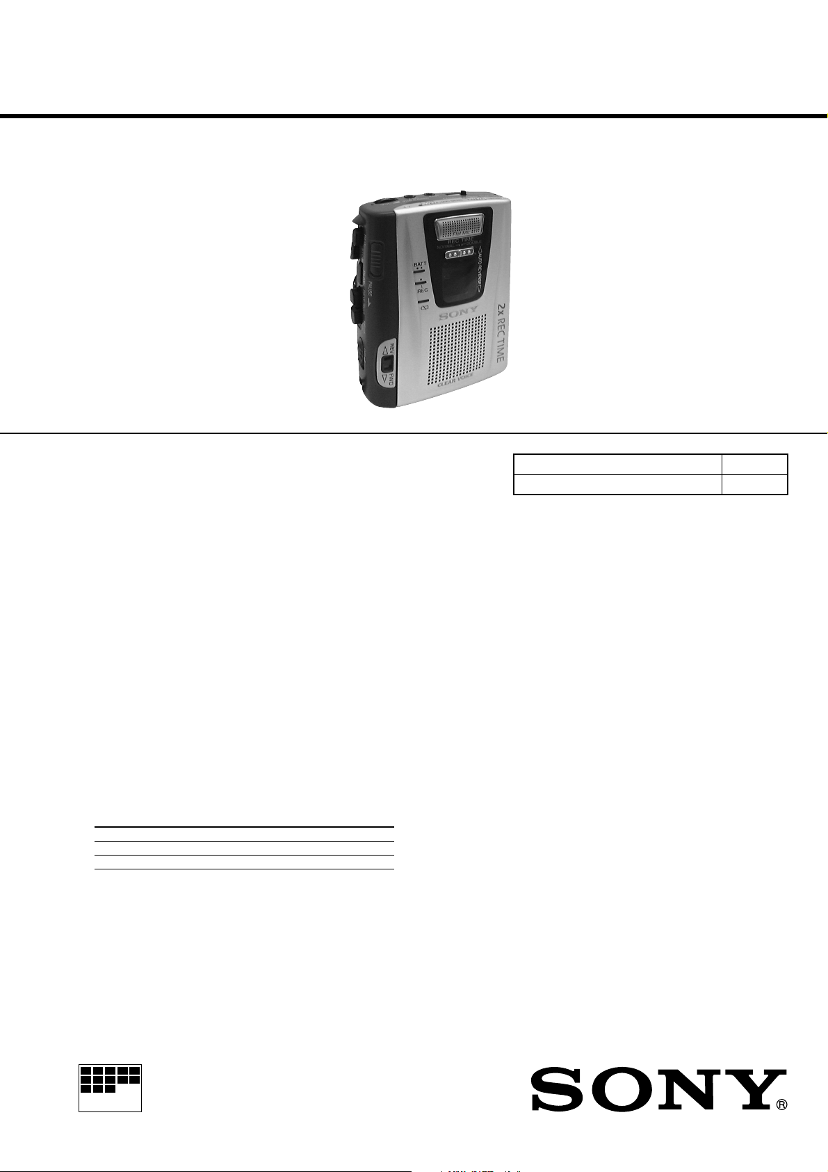
TCM-50DV
MICROFILM
SERVICE MANUAL
Ver 1.1 2000. 08
With SUPPLEMENT-1
(9-926-919-81)
SPECIFICATIONS
US Model
Canadian Model
AEP Model
E Model
Tourist Model
Model Name Using Similar Mechanism NEW
Tape Transport Mechanism Type MT-50-30
Recording system
2-track 1 channel monaural
Tape speed
4.8 cm/s or 2.4 cm/s
Frequency range
250 - 6,300 Hz using normal (TYPE I) cassette (with REC TIME switch
at “NORMAL”)
Speaker
Approx. 3.6 cm (1
Power output
250 mW (at 10% harmonic distortion)
Input
Microphone input jack (minijack) sensitivity 0.2 mV for 3 kilohms or
lower impedance microphone
Output
Earphone jack (minijack) for 8 - 300 ohms earphone
Variable range of the tape speed
From approx. +25% to –15% (with REC TIME switch at “NORMAL”)
Power requirements
3 V DC batteries AA (R6) × 2/External DC 3 V power sources
Battery life (Approx. hours) (EIAJ*)
Playback 9.5 1.5
Recording 10.5 2
* Measured value by the standard of EIAJ (Electronic Industries
Association of Japan). (Using a Sony HF series cassette tape)
7/16 in.) dia.
Sony alkaline LR6 (SG) Sony R6P (SR)
Dimensions (w/h/d) (inci. projecting parts and controls)
Approx. 88.7 × 115.3 × 37.2 mm (3
Mass
Approx. 250 g (8.9
Supplied accessories
Size AA (R6) batteries (2) (Tourist model only)
Earphone (1) (Tourist model only)
Design and specifications are subject to change without notice.
oz.)
1/2 × 4 5/8 × 1 1/2 in.)
CASSETTE-CORDER
– 1 –

TABLE OF CONTENTS
1. SERVICING NOTE ..................................................... 3
2. GENERAL
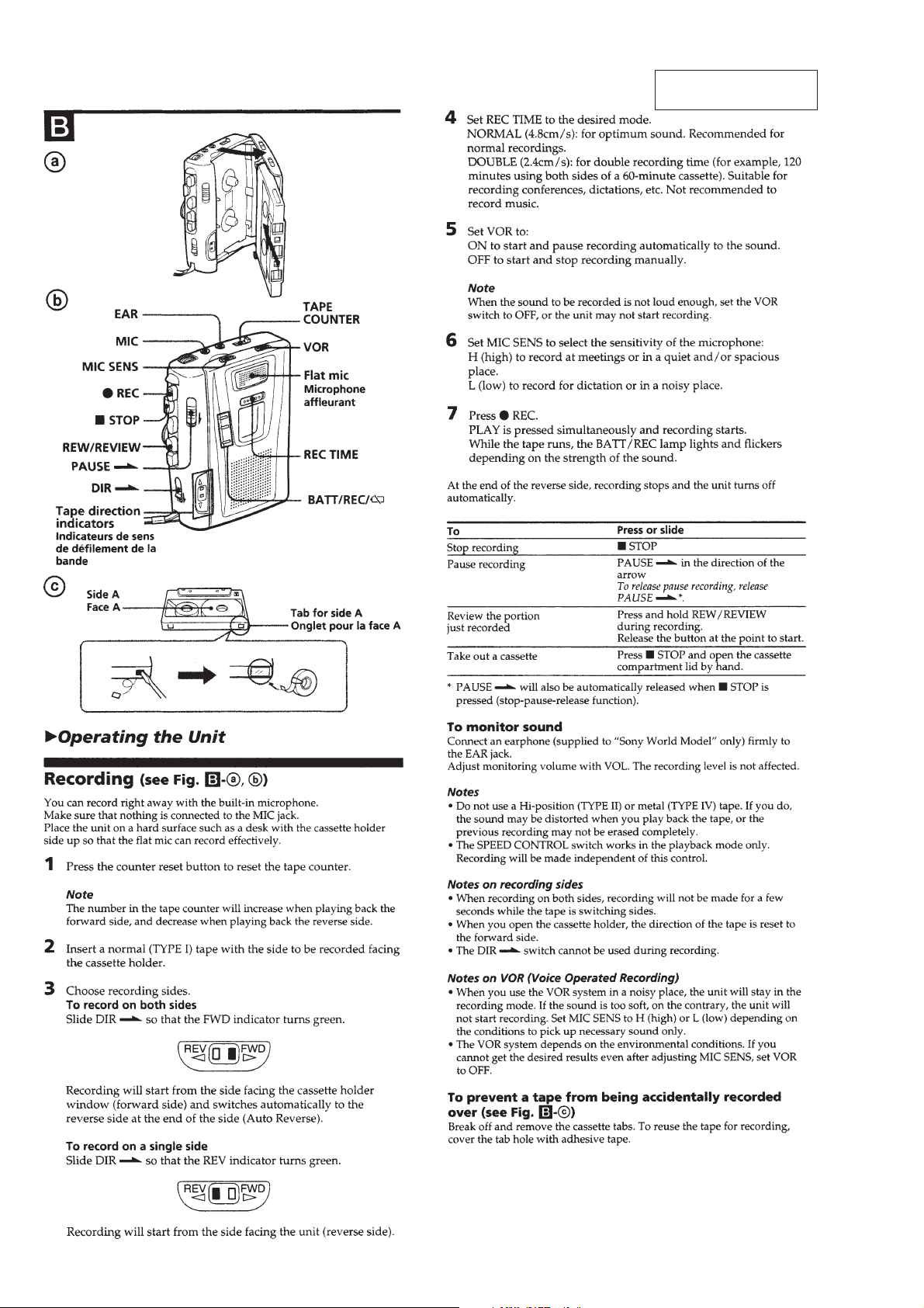
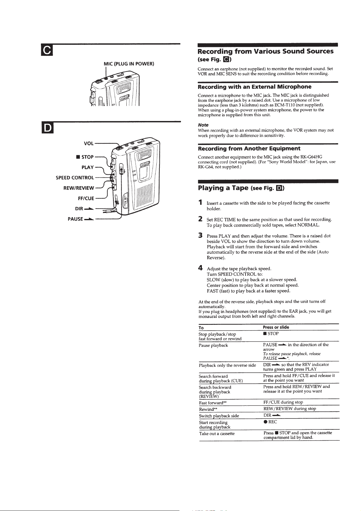
Operating the Unit ................................................................... 4
3. DISASSEMBLY
3-1. Cabinet, Cassette Lid Assy .................................................6
3-2. MAIN Board, Cassette Machanism .................................... 7
3-3. Belt ...................................................................................... 8
3-4. Head .................................................................................... 8
3-5. Motor, DC ........................................................................... 9
3-6. Note for Installation of Main Board.................................... 9
4. MECHANICAL ADJUSTMENTS............................ 10
5. ELECTRICAL ADJUSTMENTS .............................10
6. DIAGRAMS
6-1. Block Diagram .................................................................. 11
6-2. Printed Wiring Board –Main Section– .............................. 13
6-3. Schematic Diagram –Main Section–.................................15
6-4. Printed Wiring Board –Panel Section– ............................. 17
6-5. Schematic Diagram –Panel Section– ................................ 18
6-6. IC Pin Description............................................................. 20
7. EXPLODED VIEWS
7-1. Case Section ...................................................................... 21
7-2. Panel Section..................................................................... 22
7-3. Mechanism Deck Section-1 .............................................. 23
7-4. Mechanism Deck Section-2 .............................................. 24
8. ELECTRICAL PARTS LIST ....................................25
Notes on Chip Component Replacement
• Never reuse a disconnected chip component.
• Notice that the minus side of a tantalum capacitor may be dam-
aged by heat.
Flexible Circuit Board Repairing
• Keep the temperature of the soldering iron around 270˚C during
repairing.
• Do not touch the soldering iron on the same conductor of the
circuit board (within 3 times).
• Be careful not to apply force on the conductor when soldering
or unsoldering.
– 2 –
SECTION 1
SERVICING NOTE
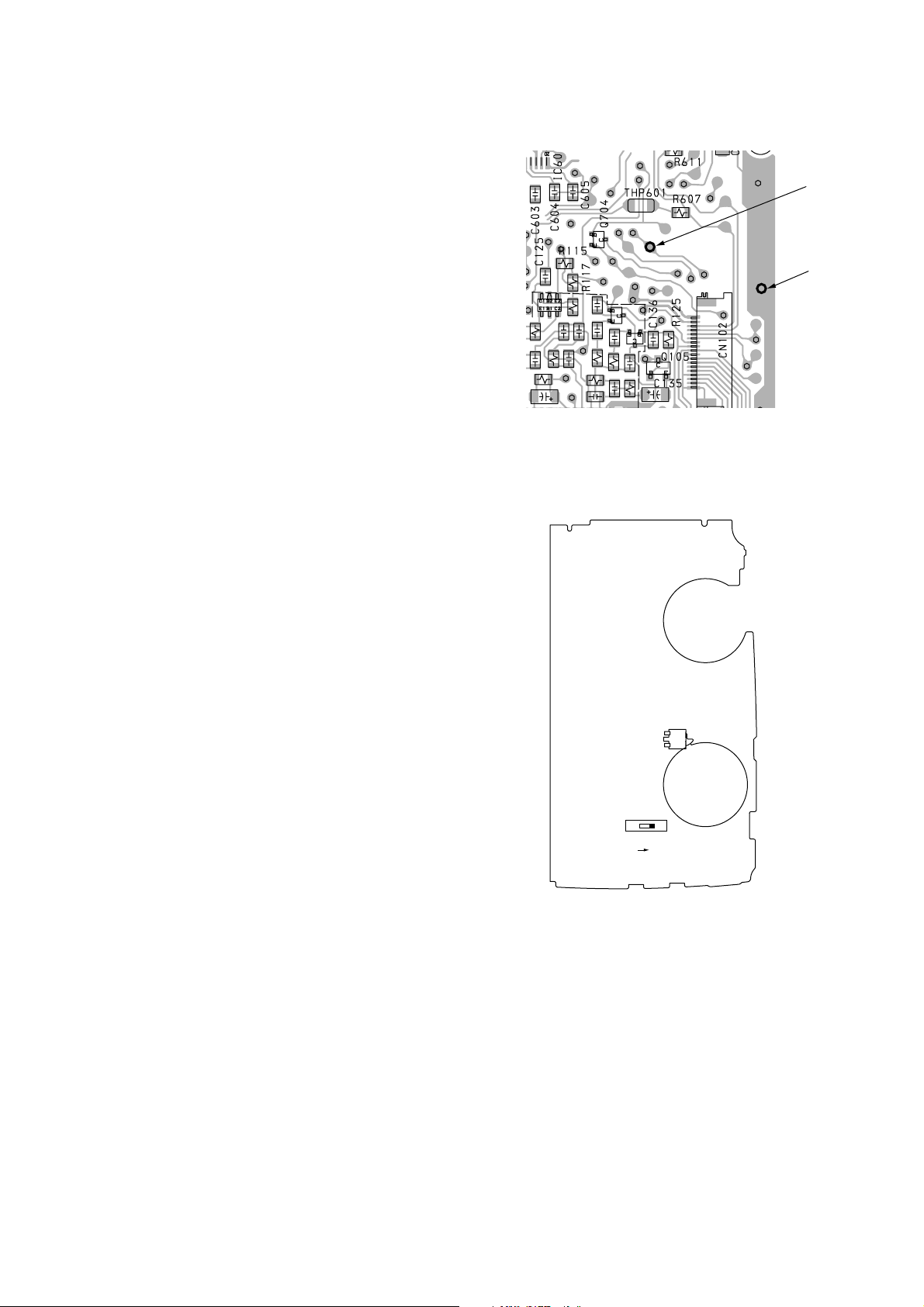
1-1. SERVICE MODE
Mode to allow the mechanical parts to operate with the main board
open.
This set uses the photo reflector PH701 to detect the rotation of the
idler gear. PH701 is on the main board and so remo val of the main
board does not allow the set to detect the rotation of the idler gear.
This makes motor control impossible which prevents normal
operation.
When repairing the set as energized with the main board removed,
proceed as follows:
1. Setting
1) Remove the cabinet (rear) (refer to the Disassembly) and open
the main board.
2) Apply a trapezoidal of 10 to 100 Hz (at 1.3 V) from oscillator to
TP20. (Connect the ground to TP30.)
3) Supply DC 3.0 V to the positive and negative terminals of the
battery with a stabilized power supply.
2. FF mode
1) Apply a trapezoidal to hall sensor TP20.
2) Press the FF key.
3) Turn on the S103 (POWER) switch.
3. REW mode
1) Apply a trapezoidal to hall sensor TP20.
2) Press the REW key.
3) Turn on the S103 (POWER) switch.
– main board (conductor side) –
TP20
– main board (component side) –
TP30
TP20
TP30
4. PLAY mode
1) Apply a trapezoidal to hall sensor TP20.
2) Press the PLAY key.
3) Change over the S101 (REC/PB) switch to PB side.
4) Turn on the S103 (POWER) switch.
5. REC mode
1) Apply a trapezoidal to hall sensor TP20.
2) Press the REC key.
3) Change over the S101 (REC/PB) switch to REC side.
4) Turn on the S103 (POWER) switch.
S103
(POWER)
S101
PB REC
– 3 –
SECTION 2
GENERAL
This section is extracted
from instruction manual.
– 4 –
– 5 –
SECTION 3
d
DISASSEMBLY
• The equipment can be removed using the following procedure.
Cabinet (rear),
Cassette Lid Assy
Note : Follow the disassembly procedure in the numerical order given.
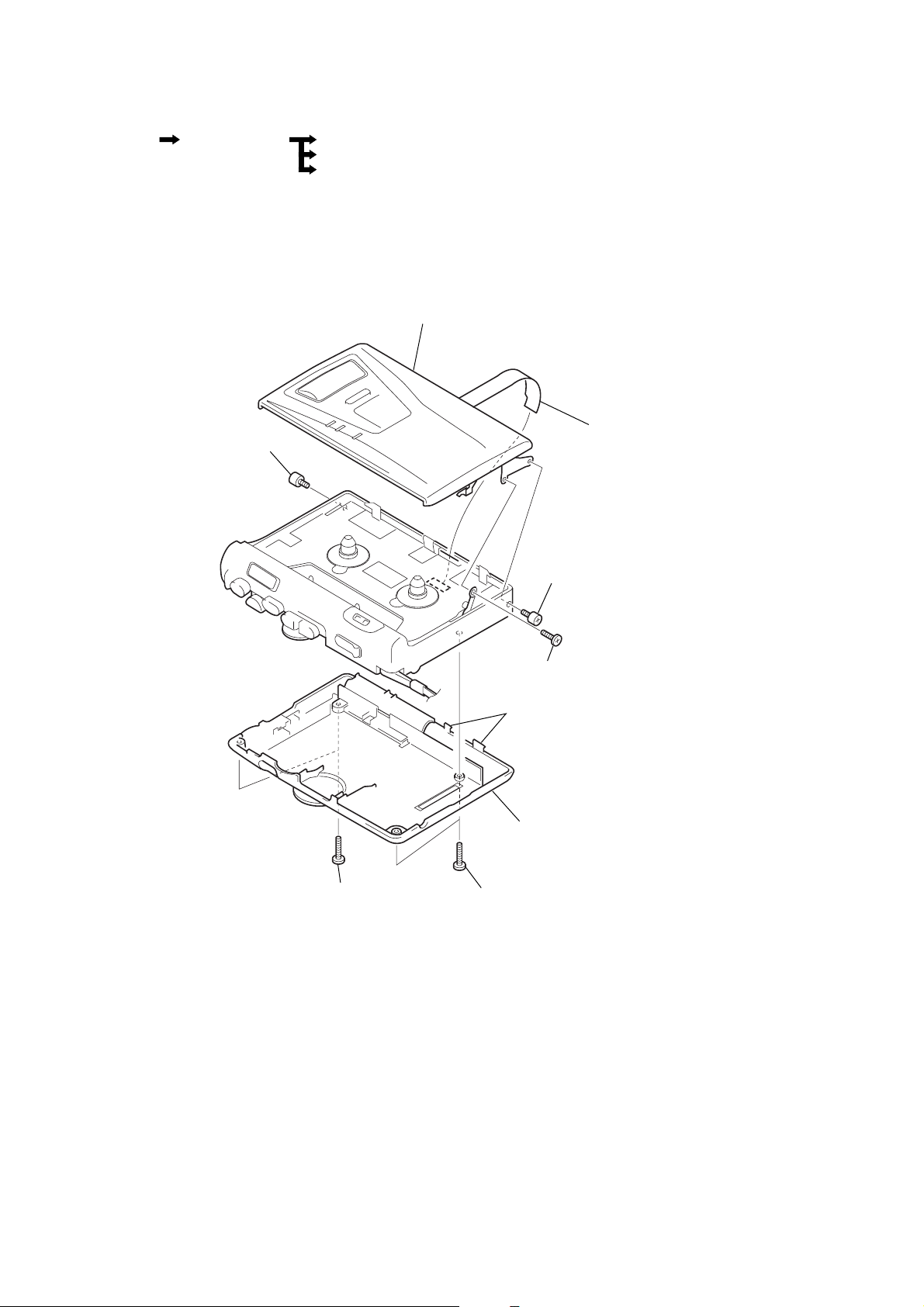
3-1. CABINET (REAR), CASSETTE LID ASSY
Mechanism Deck,
Main board
8
screw, ornamental
Belts
Head
Motor, DC
9
cassette lid assy
5
LED flexible boar
2
two screws
(screw (B1.7x9), tapping)
7
screw, ornamental
6
shaft (A), stopper
3
two claws
4
cabinet (rear)
1
two screws
(screw (B1.7x9), tapping)
– 6 –
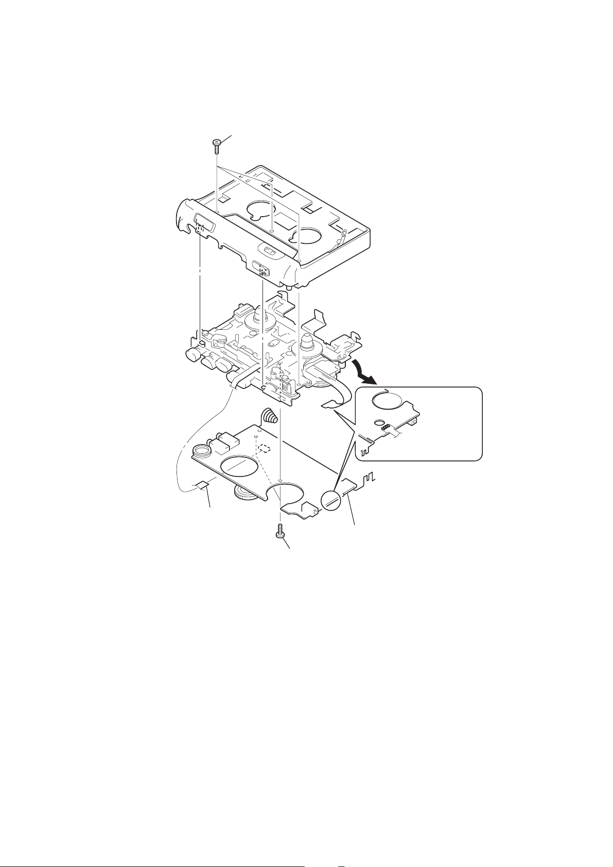
3-2. MACHANISM DECK, MAIN BOARD
1
three screws
(screw (IB lock))
2
mechanism deck,
MAIN board
4
head flexible board
6
MAIN board
5
two screws
(screw (M1.4), toothed lock)
3
Remove the four solders.
– 7 –
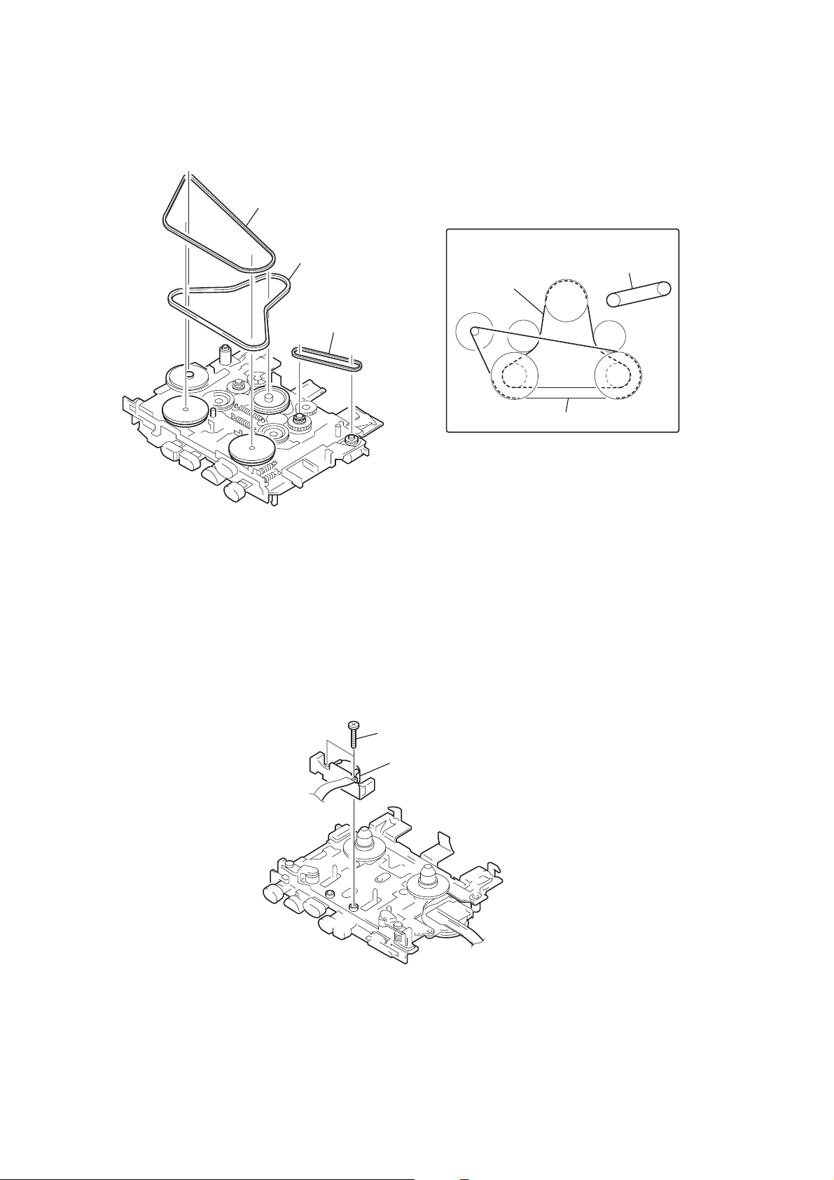
3-3. BELTS
1
belt (motor)
2
belt (flywheel)
3
belt (counter)
• How to apply the belts
belt (counter)
belt (flywheel)
belt (motor)
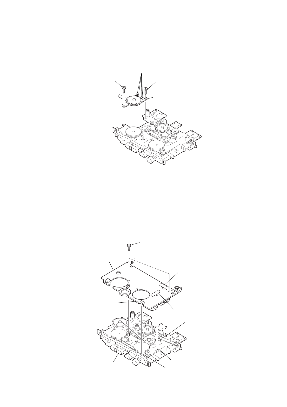
3-4. HEAD
1
two screws
2
head, magnetic
(REC/PB/ERASE)
– 8 –
3-5. MOTOR, DC
2
screw (1.4)
3
Remove the four solders.
1
screw (1.4)
4
Motor, DC
3-6. NOTE FOR INSTALLATION OF MAIN BOARD
Align the knobs of S101, S103 and S701 on the main board with the
claws of the lever (REC) le ver (erase proof 2) and lever (REC) of the
mechanism deck respectively, and install the main board.
screws (M1.4), toothed lock
MAIN board
S701
S103
S101
lever (erase proof 2)
mechanism deck
lever (REC)
lever (PAUSE)
– 9 –
 Loading...