

Sony TCM-450-DV Service manual
TCM-450DV
SERVICE MANUAL
Ver 1.2 2004. 07
Model Name Using Similar Mechanism New
Tape transport Mechanism Type MT-450-175
SPECIFICATIONS
US Model
Canadian Model
AEP Model
E Model
Chinese Model
Tourist Model
Recording system
2-track 1 channel monaural
Speaker
Approx. 3.6 cm (1 7⁄16 in.) dia.
Tape speed
4.8 cm/s (1 7⁄8 ips) or 2.4 cm/s (15⁄16 ips)
Variable range of the tape speed
From approx. +30% to –20% (with REC TIME/PLAY MODE
switch at “NORMAL”)
Frequency range
250 - 6,300 Hz using nomal (TYPE I) cassette
(with REC TIME/PLAY MODE switch at “NORMAL”)
Input
Microphone input jack (minijack/ monaural/PLUG IN POWER)
sensitivity 0.2 mV for 3 kΩ or lower impedance microphone
Output
Earphone jack (minijack/ monaural) for 8 - 300 Ω earphone
Power output (at 10 % harmonic distortion)
450 mW
Power requirements
3 V DC, batteries R03 (AAA) x 2/
External DC 3 V power sources
Dimensions (w/h/d) (incl. projecting parts and controls)
Approx. 86.3 x 113.4 x 28.9 mm
(3 1⁄2 x 4 1⁄2 x 1 3⁄16 in.)
Mass (main unit only)
Approx. 173 g (6.2 oz.)
Supplied accessory
Carrying pouch (1)
Design and specifications are subject to change without notice.
9-877-551-03
2004G02-1
© 2004.07
CASSETTE-CORDER
Sony Corporation
Personal Audio Company
Published by Sony Engineering Corporation

TCM-450DV
TABLE OF CONTENTS
1. GENERAL ................................................................... 2
SECTION 1
GENERAL
This section is extracted from
instruction manual.
2. DISASSEMBLY.......................................................... 3
2-1. Cabinet (Rear) ......................................................... 3
2-2. Main Board ............................................................. 4
2-3. Mechanism Deck (MT-450-175)............................. 4
2-4. Belt (Counter), Belt (Cap)S,
M901 (Capstan/Reel Motor), HRP901
(REC/PB Head), HE901 (ERASE HEAD) .............5
2-5. Cassette Lid Assy, Led Board .................................5
3. MECHANICAL ADJUSTMENTS .......................6
4. ELECTRICAL ADJUSTMENTS ......................... 6
5. DIAGRAMS
5-1. Block Diagrams....................................................... 7
5-2. Printed Wiring Board –MAIN Section (Side A) – .. 8
Printed Wiring Board –MAIN Section (Side B) – ..9
5-3. Schematic Diagram –MAIN Section (1/2) –........... 10
5-4. Schematic Diagram –MAIN Section (2/2) –........... 11
5-5. IC BLOCK DIAGRAMS ........................................ 12
6. EXPLODED VIEWS
6-1. Cassette Lid, Cabinet (Rear) Section ......................13
6-2. Cabinet (Front) Section ........................................... 14
6-3. Mechanism Deck Section-1 (MT-450-175) ............ 15
6-4. Mechanism Deck Section-2 (MT-450-175) ............ 16
VOR
Microphone
z
REC
x STOP
m REW/REVIEW
PAUSE .
REC TIME/
PLAY MODE*
Tape counter
reset button
TAPE COUNTER
EAR
MIC (PLUG
IN POWER)*
REC/BATT
DC IN 3V
* The button/jack has a tactile dot.
7. ELECTRICAL PARTS LIST................................ 17
Flexible Circuit Board Repairing
• Keep the temperature of the soldering iron around 270 ˚C dur-
ing repairing.
• Do not touch the soldering iron on the same conductor of the
circuit board (within 3 times).
• Be careful not to apply force on the conductor when soldering
or unsoldering.
Notes on chip component replacement
• Never reuse a disconnected chip component.
• Notice that the minus side of a tantalum capacitor may be dam-
aged by heat.
2

DISASSEMBLY
d
• This set can be disassembled in the order shown below.
TCM-450DV
SECTION 2
Set
Cabinet (front)
Cabinet (Rear)
Note: Follow the disassembly procedure in the numerical order given.
Main board
Cassette lid assy, LED board
Mechanism deck
2-1. CABINET (REAR)
• On installation cabinet (rear),
adjust the S501 and knob (VOR).
S501
RV101
7
speaker (SP1)
Belt (Counter), Belt (CAP) S, M901 (Capstan/reel motor),
HRP901 (REC/PB head), HE901 (ERASE head)
1
two screws (B1.7 X 9)
cabinet (front)
5
Remove solder on MAIN boar
(two places)
RV201
6
two screws
(B2.0)
knob (VOR)
4
3
claw
knob (VOL)
• On installation cabinet (rear),
adjust the RV101 and knob
(VOL).
knob (speed) sub assy
8
cabinet (rear)
MAIN board
2
two screws (1.7 X 3)
• On installation cabinet (rear),
adjust the RV201 and knob
(speed) sub assy.
3

TCM-450DV
r
k
2-2. MAIN BOARD
• On installation MAIN board,
adjust the S301 and knob (pause).
knob (pause)
6
cabinet (front)
1
Remove solder
(three places)
RED
BLK
2
Remove solde
(eight places)
S301
7
MAIN board
3
screw (B1.7 X 9)
2-3. MECHANISM DECK (MT-450-175)
4
screw (1.4 X 3)
1
two screws (M1.4)
2
5
screw
screw (1.4 X 4.5)
RED
BLK
ORG
GRY
5
spring (ground)
3
cabinet (front)
4
mechanism dec
(MT-450-175)
4
TCM-450DV
)
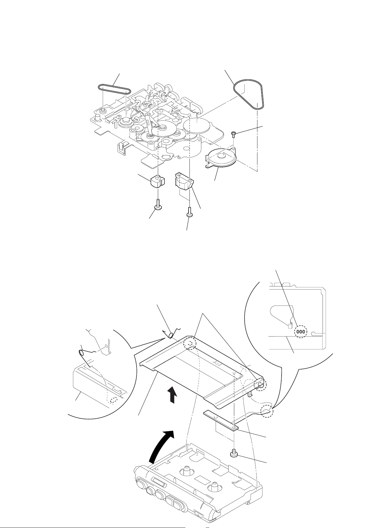
• Install the cassette lid assy with
the cassette-up spring as shown
in the figure so that it fits into the
holes on the casstte lid assy.
2
4
1
Remove solder on MAIN board
(three places)
MAIN board
3
projection
5
cassette-up spring
6
cassette lid assy
7
two screws (M1.4)
8
LED board
cassette lid assy
cassette-up spring
cabinet (front)
2-4. BEL T (COUNTER), BEL T (CAP) S, M901 (CAPST AN/REEL MO TOR), HRP901 (REC/PB HEAD),
HE901 (ERASE HEAD)
2
1
8
HE901 (ERASE head)
belt (counter)
belt (CAP) S
4
M901 (capstan/reel motor)
3
two screws (M1.4X1.4
2-5. CASSETTE LID ASSY, LED BOARD
7
screw (M1.4X4.5)
6
HRP901(REC/PB head)
5
two screws (M1.4X1.4)
5
TCM-450DV
SECTION 3
MECHANICAL ADJUSTMENTS
1. Clean the following parts with a denatured-alcohol-moistened
swab:
record/playback head pinch roller
erase head rubber belt
capstan
2. Demagnetize the record/playback head with a head
demagnetizer. (Do not bring the head demagnetizer close to
the erase head.)
3. Do not use a magnetized screwdriver for the adjustments.
4. After the adjustments, apply suitable locking compound to
the parts adjusted.
5. The adjustments should be performed with the rated power
supply voltage (2.5 V) unless otherwise noted.
SECTION 4
ELECTRICAL ADJUSTMENTS
Setting:
• Supplied voltage: 2.5 V
• Switch and control position
VOL contorl (RV101) : mechanical center
PAUSE switch (S301) : OFF
SPEED CONTROL (RV201) : center click
VOR switch (S501) : OFF
Test T ape
Type Signal Used for
WS-48A 3 kHz, 0 dB tape speed adjustment
0 dB=0.775 V
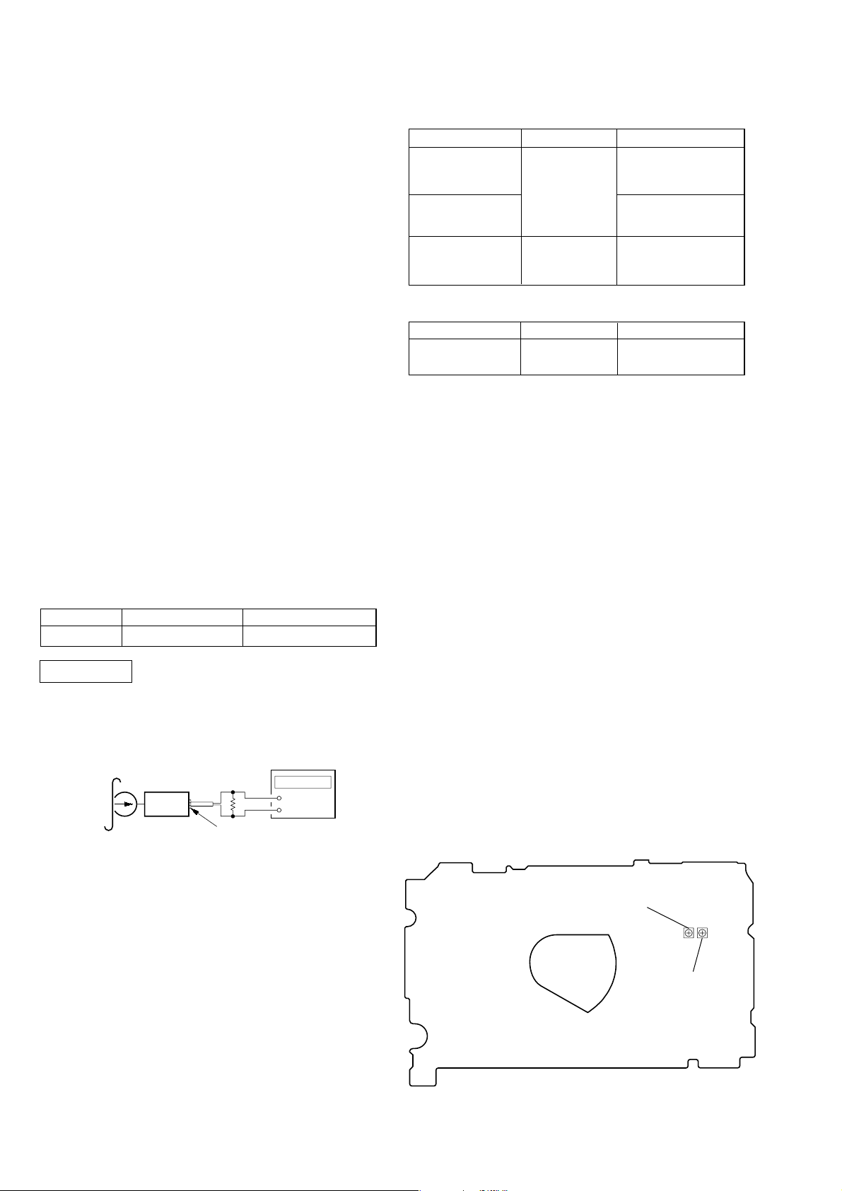
Tape Speed Adjustment
Mode: playback
test tape
WS-48A
(3 kHz, 0 dB)
16 Ω
set
EAR jack (J102)
frequency
counter
+
–
Torque Measurement
Mode Torque Meter Meter Reading
FWD (20 – 40 g•cm)
CQ-102C
Forward Back
Tension
FF, REW CQ-201B
1.97 – 3.92mN•m
(0.28 – 0.55 oz•inch)
0.05 – 0.49 mN•m
(0.5– 5 g•cm)
(0.007 – 0.069 oz•inch)
more than 4.91 mN•m
(more than 50 g•cm)
(more than 0.69 oz•inch)
Tape Tension Measurement
Mode Tension Meter Meter Reading
FWD CQ-403A
more than 50 g
(more than 1.76 oz)
Procedure:
1. Set
[RECTIME/PLAYMODE] switch (S601) to NORMAL
(4.8 cm/s) position, and playback the tape (WS-48A) .
2. Adjust RV601 so that frequency counter reading becomes
3,000 Hz.
Specification values: 2,985 to 3,015 Hz
3. Set
[RECTIME/PLAYMODE] switch (S601) to DOUBLE
(2.4 cm/s) position.
4. Playback the tape from the beginning for two minutes, then
adjust R V602 so that frequency counter reading becomes 1,500
Hz.
Specification values: 1,493 to 1,507 Hz
Confirm that deflection of the frequency counter reading between
the beginning and the end of tape is within 2% (NORMAL: approx.
60 Hz, DOUBLE: approx. 30 Hz) .
Adjustment Location:
– MAIN BOARD (Side B) –
RV601
Tape Speed Adjustment
(Normal Speed)
RV602
Tape Speed Adjustment
(Double Speed)
6
 Loading...