

Sony TAV-606 Service manual
TA-V606/ VE610
SERVICE
Manufactured under license from Dolby Laboratories Licensing
Corporation.
“Dolby”, the double-D symbol a and “Pro Logic” are trademarks
of Dolby Laboratories Licensing Corporation.
Amplifier section
POWER OUTPUT
Stereo mode V606 : (6 ohms 1kHz, THD 0.7 %)
Surround mode V606 : (6 ohms at 1kHz, THD 0.7 %)
5.1 mode V606 : (6 ohms at 1kHz, THD 0.7 %)
Harmonic distortion at rated output
Frequency respones
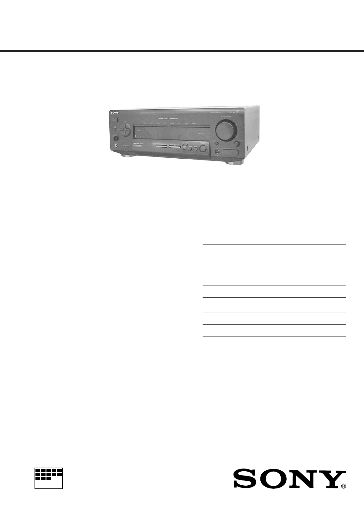
MANUAL
Photo : TA-VE610
SPECIFICATIONS
110 W + 110W
VE610 :(4 ohms 1kHz, THD 0.7 %)
100 W + 100W
Front : 110 W/ch
Center* : 110 W
Rear* : 110 W/ch
VE610 :(4 ohms at 1kHz, THD 0.7 %)
Front : 100 W/ch
Center* : 100 W
Rear* : 100 W/ch
*Depending on the sound field settings and the
source, sound will not be output.
Front : 110 W/ch
Center : 110 W
Rear : 110 W/ch
VE610 :(4 ohms at 1kHz, THD 0.7 %)
Front : 100 W/ch
Center : 100 W
Rear : 100 W/ch
Less than 0.09% (with DIRECT PASS on)
PHONO : RIAA equalization curve
± 0.5dB
CD, TAPE, DAT/MD, VIDEO 1, 2 :
+0
10Hz – 50 kHz – 1 dB (with DIRECT PASS on)
AEP Model
UK Model
E Model
Chinese Model
Inputs
Sensitivity Impedance network, input
PHONO 2.5mV 50 kilohms
TUNER 150mV 50 kilohms
CD 200mV 50 kilohms
TAPE/MD,VIDEO1, 2, 3 150mV
TV/LD (AEP, UK model) 150mV
TV/LD
(EXCEPT AEP, UK model)
5.1 INPUT 200mV 50 kilohms
* ’78 IHF
Outputs VIDEO 1, 2, 3, AUDIO OUT :
BASS BOOST +10 dB at 70 Hz
TONE ± 8 dB at 100Hz and 10 kHz
250mV 50 kilohms
Voltage : 150 mV, Impedance : 10 kilohms
WOOFER :
Voltage : 2 V
Impedance : 1 kilohms
PHONES :
Accepts low and high impedance headphones
50 kilohms
– Continued on page 2 –
TA-VE610
TA-V606
S/N (weighting
level)
75 dB*
(A, 2.5mV)
82 dB*
(A, 150mV)
82 dB*
(A, 200mV)
82 dB*
(A, 150mV)
82 dB*
(A, 250mV)
82 dB*
(A, 200mV)
MICROFILM
INTEGRATED AV AMPLIFIER

Video section
Inputs 1 Vp-p 75 ohms
Outputs 1 Vp-p 75 ohms
General
System Preamplifier section :
Low-noise NF type equalizer
Power amplifier section :
Pure-complementary SEPP
Power requirements AEP, Singapore, Malaysia model :
230 V AC, 50/60Hz
UK model : 240 V AC, 50/60Hz
Chinese model : 220 V AC, 50/60Hz
Power consumption 240W
AC outlets EXCEPT Chinese model :
1 switched, maximum 100W
Chinese model : 2 switched, total 100 W
Dimensions 430 x 155 x 350 mm
including projecting parts and controls
Mass (Approx.) 9.8 kg
Supplied accessories Remote commander (remote) RM-U501 (1)
Size AA (R6) batteries (2)
Design and specifications are subject to change without notice.
TABLE OF CONTENTS
Specifications ........................................................................... 1
1. GENERAL
Location and Function of Controls .................................... 3
2. DIAGRAMS
2-1. IC Pin Function........................................................... 5
2-2. Circuit Boards Locations ............................................ 7
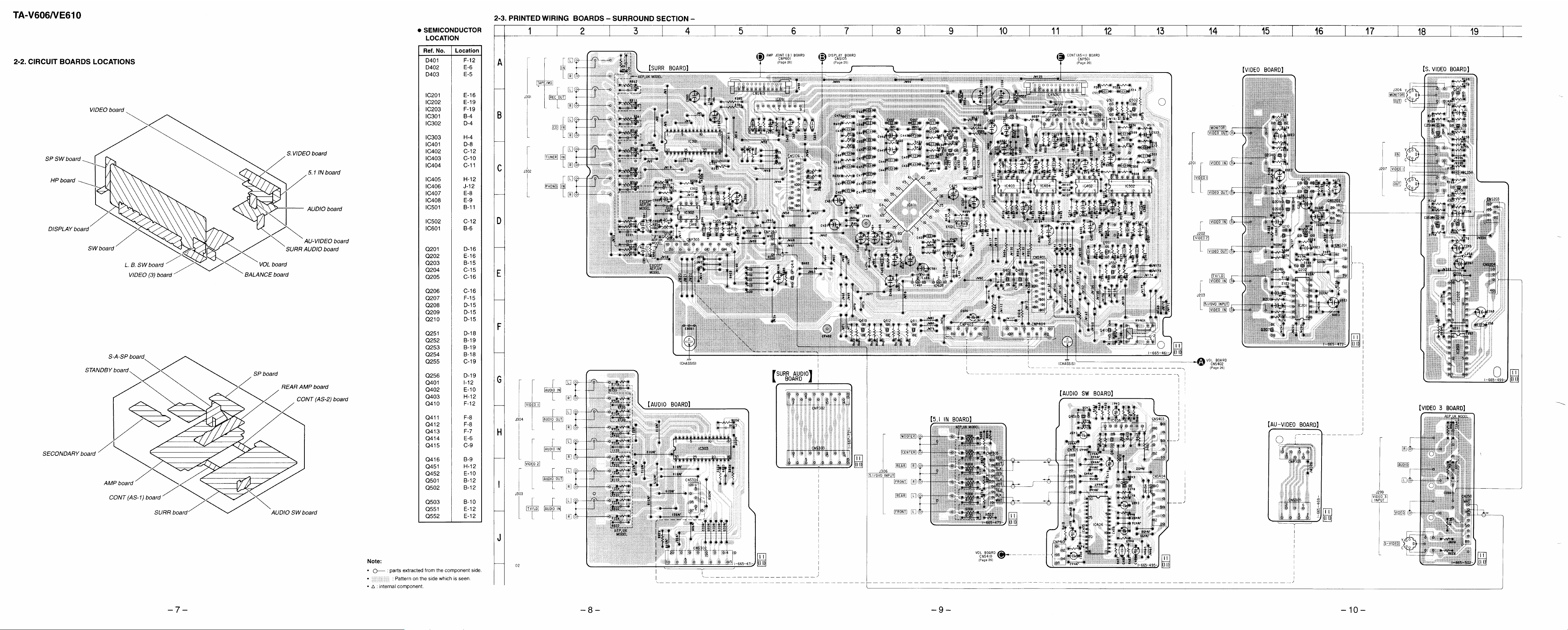
2-3. Printed Wiring Boards – Surround Section – ............. 8
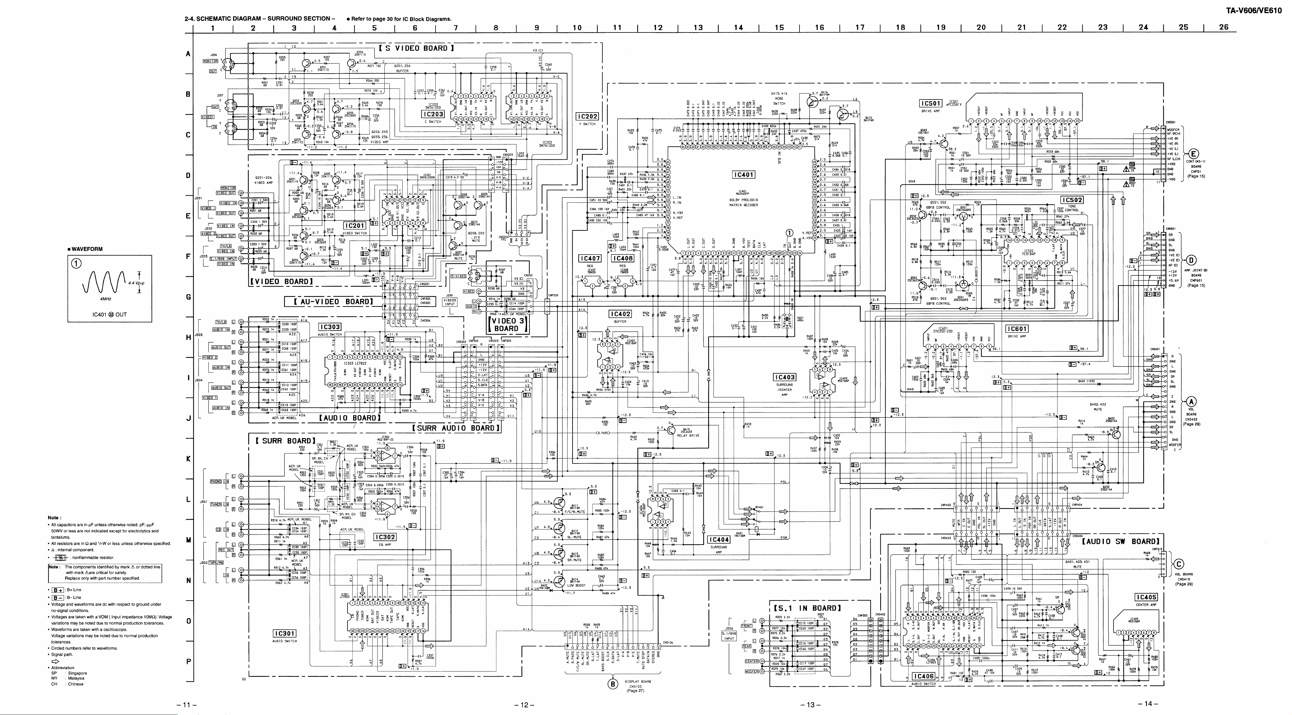
2-4. Schematic Diagram – Surround Section –............... 11
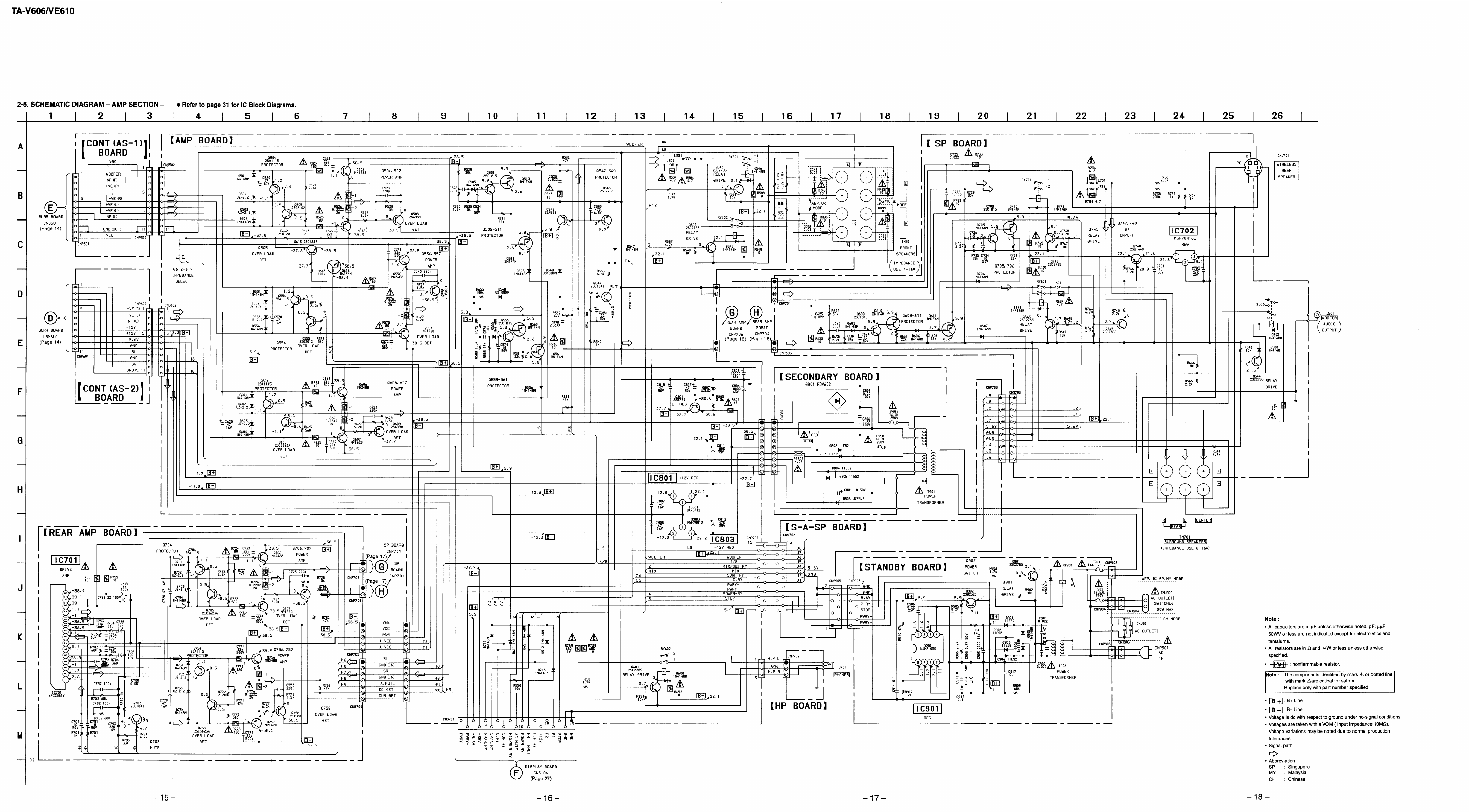
2-5. Schematic Diagram – AMP Section – ..................... 15
2-6. Printed Wiring Boards – AMP Section – .................. 19
2-7. Printed Wiring Boards – Display Section –............. 23
2-8. Schematic Diagram – Display Section – .................. 27
3. EXPLODED VIEWS
3-1. Front Panel Section................................................... 32
3-2. Chassis Section ......................................................... 33
3-3. Back Panel Section ................................................... 34
4. ELECTRICAL PARTS LIST ........................................ 35
SAFETY-RELATED COMPONENT WARNING!!
COMPONENTS IDENTIFIED BY MARK ! OR DO TTED LINE WITH
MARK ! ON THE SCHEMATIC DIAGRAMS AND IN THE PARTS
LIST ARE CRITICAL TO SAFE OPERATION.
REPLACE THESE COMPONENTS WITH SONY PARTS WHOSE
PART NUMBERS APPEAR AS SHOWN IN THIS MANUAL OR IN
SUPPLEMENTS PUBLISHED BY SONY.
– 2 –
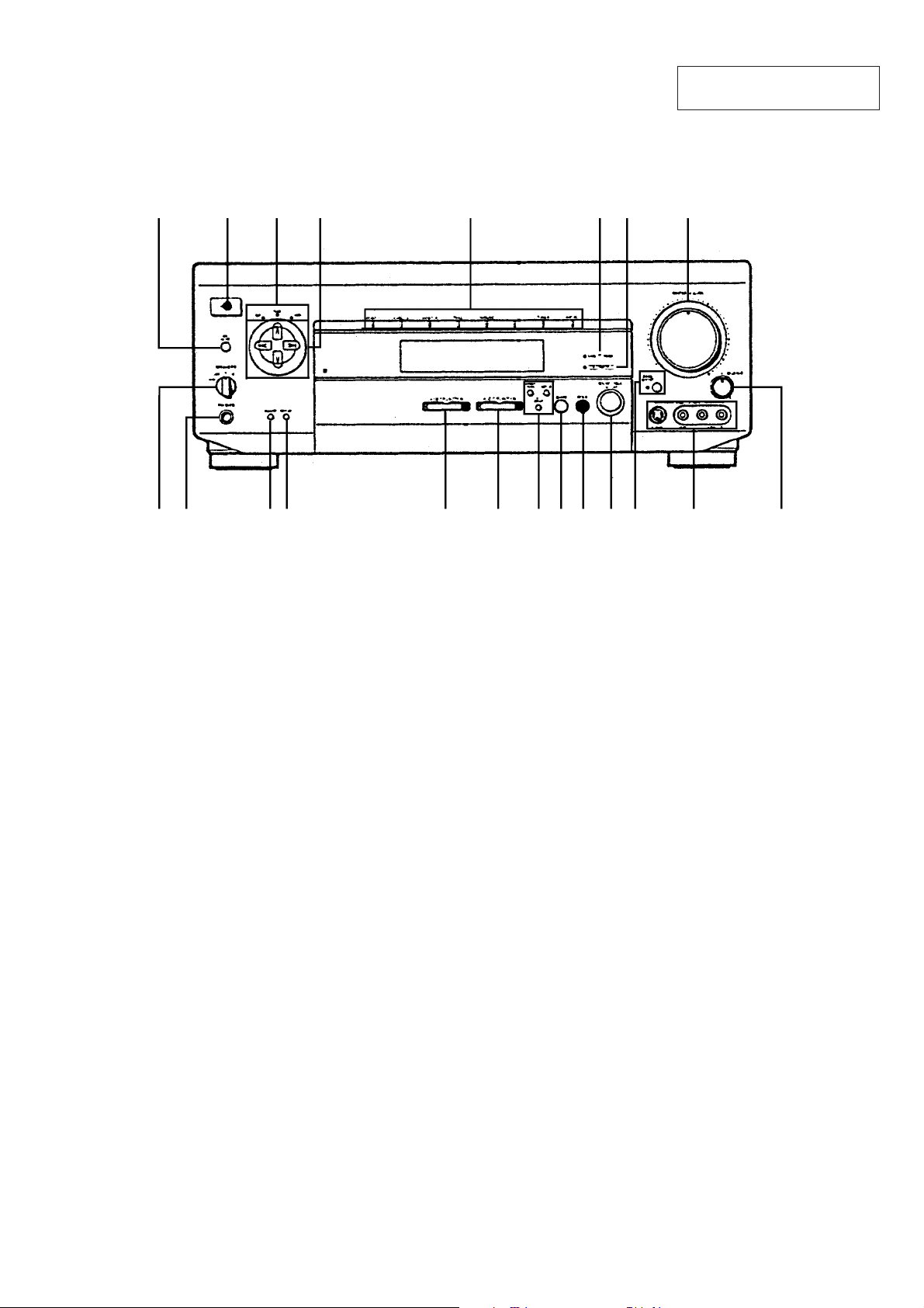
LOCATION AND FUNCTION OF CONTROLS
[FRONT PANEL]
SECTION 1
GENERAL
This section is extracted from
instruction manual.
1 8532
1 DPC MODE button
2 POWER switch
3 SUR, TONE, INDEX indicators
4 Digital processing control buttons
5 Function indicators
6 DIRECT PASS indicator
7 5.1 INPUT indicator
8 MASTER VOLUME control
9 BALANCE control
!º VIDEO 3 INPUT jacks
!¡ BASS BOOST button/indicator
674
!™!¶ !§ !£!¢!∞!•!ª@º@¡ !º 9
!¡
!™ SOUND FIELD ON/OFF button
!£ MODE button
!¢ GENRE button
!∞ DIRECT PASS, SET UP, 5.1/DVD INPUT buttons
!§ AUDIO FUNCTION buttons
!¶ VIDEO FUNCTION buttons
!• DISPLAY button
!ª DIMMER button
@º PHONES jack
@¡ SPEAKERS switch
– 3 –
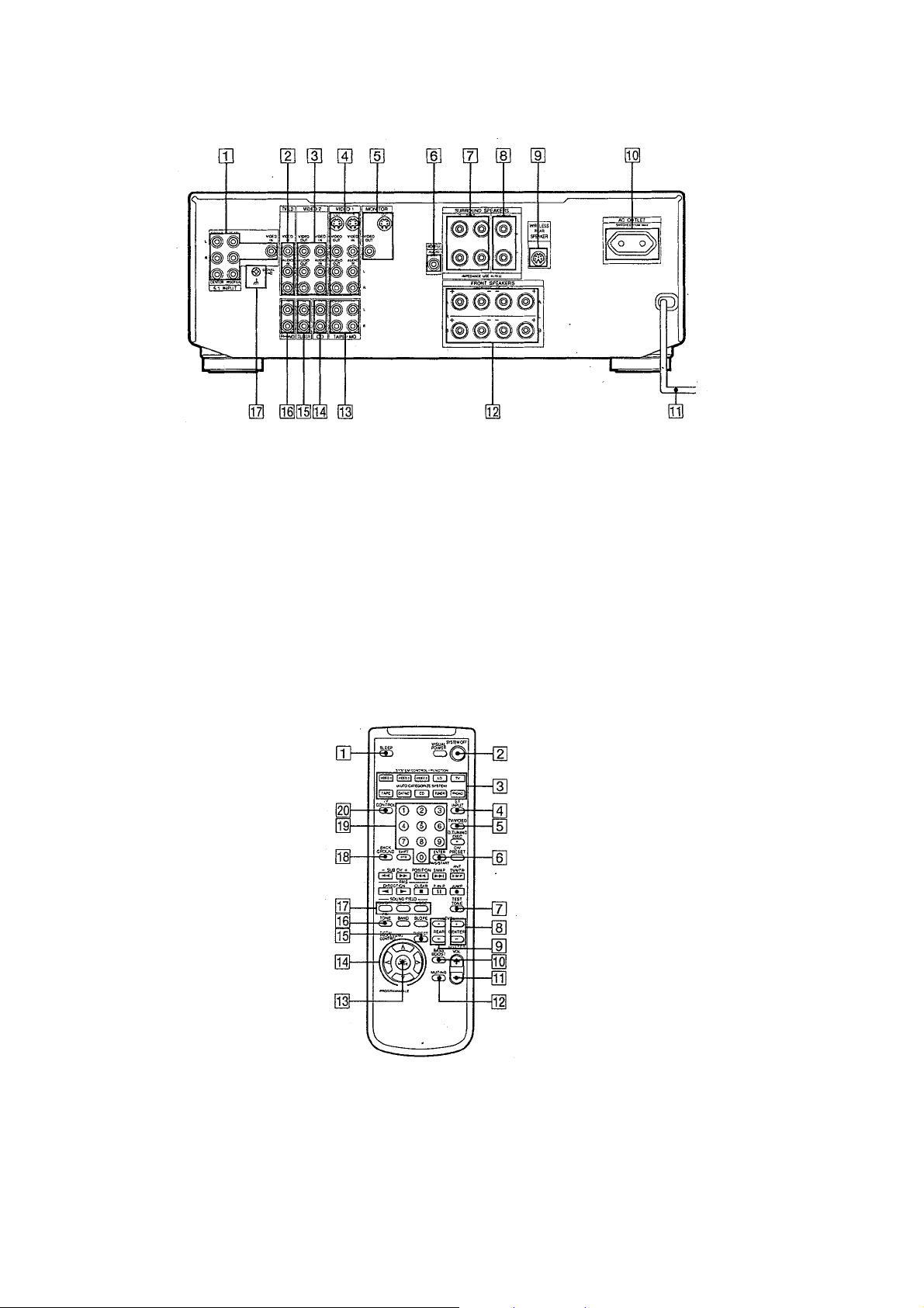
[REAR PANEL]
[REMOTE]
1 5.1 INPUT
2 TV/LD
3 VIDEO 2
4 VIDEO 1
5 MONITOR
6 WOOFER
7 SURROUND SPEAKERS (REAR)
8 SURROUND SPEAKERS (CENTER)
9 WIRELESS REAR SPEAKER
!º AC OUTLET
(Outlet shape and position varies
according to destination)
!¡ AC power cord
!™ FRONT SPEAKERS (A/B)
!£ TAPE/MD
!¢ CD
!∞ TUNER
!§ PHONO
!¶ y SIGNAL GND
1 SLEEP
2 SYSTEM OFF
3 SYSTEM CONTROL/FUNCTION
4 5.1 INPUT
5 TV/VIDEO
6 ENTER
7 TEST TONE
8 CENTER LEVEL +/–
9 REAR LEVEL +/–
!º BASS BOOST
!¡ MASTER VOL +/–
!™ MUTING
!£ DPC MODE
!¢ DIGITAL PROCESSING CONTROL
!∞ DIRECT
!§ EQ/TONE
!¶ SOUND FIELD ON/OFF/GENRE/MODE
!• BACKGROUND
!ª Numeric buttons
@º TV CONTROL ON
– 4 –
SECTION 2
DIAGRAMS
2-1. IC PIN FUNCTION
IC103 µPD780205GF-032-3BA (SYSTEM CONTROL)
Pin No. Pin name I/O Description
1 –––– – Not used (Connect to VDD).
2 to 4 –––– – Not used (Connect to ground).
5 F/C/W. MUTE O Front, Center, Woofer mute drive.
6 SL MUTE O Surround L-CH mute drive.
7 SR MUTE O Surround R-CH mute drive.
8 AC MUTE O AC mute drive.
9 D LATCH O Data latch output.
10 RESET I Reset terminal.
11 X2 O System clock (4.19MHZ).
12 X1 I System clock (4.19MHZ).
13 VSS – Ground.
14 NP – Not used (Open).
15 –––– – Connect to reset terminal.
16 VDD – Power supply (+5V).
17 T LATCH O Tuner function latch output.
18 S CLOCK O Serial clock output.
19 S DATA O Serial data output.
20 S LATCH O Serial latch output.
21 AUTO STOP – Not used (Connect to ground).
22 V MUTE O Video mute output.
23 STEREO – Not used (Connect to ground).
24 IF DATA IN – Not used (Open).
25 GND A/D – Ground for A/D converter.
26 SIRCS I Remote control signal input.
27 POWER KEY I Power key input.
28 VERSION I Destination select input.
29 KEY 5 I Key input.
30 KEY 4 I Key input.
31 KEY 3 I Key input.
32 KEY 2 I Key input.
33 KEY 1 I Key input.
34 VDD A/D – Power supply (+5V) for A/D converter.
35 VREF A/D I Reference voltage for A/D converter.
36 V-A O Video switch control output.
37 V-B O Video switch control output.
38 V-E O Video switch control output.
39 STOP O Power ON/OFF control output.
40 VSS – Ground.
41 DIRECT PASS O Direct pass relay drive.
42 SUR RY O Surround relay drive.
43 CENTER RY O Center relay drive.
44 FRONT RY O Front relay drive.
45 MIX SUB RY O Woofer relay drive.
– 5 –

Pin No. Pin name I/O Description
46 VDD – Power supply (+5V).
47 PROTECTOR IN I Protector operation input.
48 POWER RY O Power relay drive.
49 BASS BOOST O Bass boost ON/OFF control.
50 SP OFF I Speaker switch input.
51 VOL – O Volume down control output.
52 VOL + O Volume up control output.
53 VOL LED O Volume LED drive.
54 STANDBY LED – Not used (Open).
55 ––––– – Not used (Open).
56 BASS BOOST LED O BASS BOOST LED drive.
57 5.1 INPUT LED O 5.1 INPUT LED drive.
58 DIRECT PASS LED O DIRECT PASS LED drive.
59 SUR LED O SUR LED drive.
60 TONE LED O TONE LED drive.
61 VIDEO 1 LED O VIDEO 1 LED drive.
62 INDEX LED O INDEX LED drive.
63 PHONO LED O PHONO LED drive.
64 TUNER LED O TUNER LED drive.
65 DAT MD LED O CD LED drive.
66 CD LED O TAPE/MD LED drive.
67 TAPE LED O TV/LD LED drive.
68 TV/DBS LED O VIDEO 3 LED drive.
69 VIDEO2 LED O VIDEO 2 LED drive.
70 to 78 P1 – P9 O FL segment drive.
79 V LOARD – FL power supply (– 35V).
80 to 87 P10 – P17 O FL segment drive.
88 to 100 G1 – G13 O FL grid drive.
– 6 –
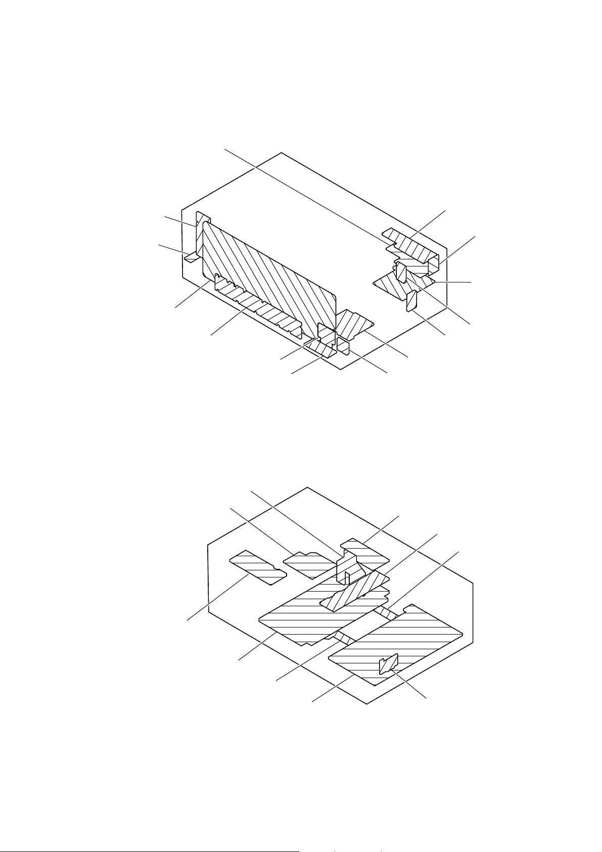
2-2. CIRCUIT BOARDS LOCATIONS
d
VIDEO board
SP SW board
HP board
DISPLAY board
SW board
S-A-SP board
L. B. SW board
VIDEO (3) board
S.VIDEO board
5.1 IN board
AUDIO board
AU-VIDEO board
SURR AUDIO board
VOL board
BALANCE board
STANDBY board
SECONDARY board
AMP board
CONT (AS-1) board
SURR board
SP board
AUDIO SW board
REAR AMP board
CONT (AS-2) boar
– 7 –
 Loading...