

Sony TASP-55 Service manual
TA-SP55
SERVICE MANUAL
TA-SP55 is the amplifier section
in CMT-SP55MD or CMT-SP55TC.
SPECIFICATIONS
AEP Model
UK Model
E Model
European model:
DIN power output (Rated): 25 + 25 watts (8 ohms at 1 kHz,
Continuous RMS power output (Reference):
Music power output (Reference):
Other models:
DIN power output (Rated): 25 + 25 watts (8 ohms at 1 kHz,
Continuous RMS power output (Reference):
Output
PHONES (stereo phono jack):
DIN, 230 V)
30 + 30 watts (8 ohms at 1 kHz,
10% THD, 230 V)
75 + 75 watts
DIN, 240 V)
22 + 22 watts (8 ohms at 1 kHz,
DIN, 220 V)
30 + 30 watts (8 ohms at 1 kHz,
10% THD, 240 V)
28 + 28 watts (8 ohms at 1 kHz,
10% THD, 220 V)
accepts headphones of 8 ohms or
more.
General
Power requirements
European model: 230 V AC, 50/60 Hz
Other models: 110 – 120 V or 220 – 240 V
Power consumption 70 watts
Dimensions (w/h/d)
Mass
Design and specifications are subject to change
without notice.
AC, 50/60 Hz
Approx. 202 x 101 x 306 mm
Approx.
3.9 kg
MICRO Hi-Fi COMPONENT SYSTEM
1
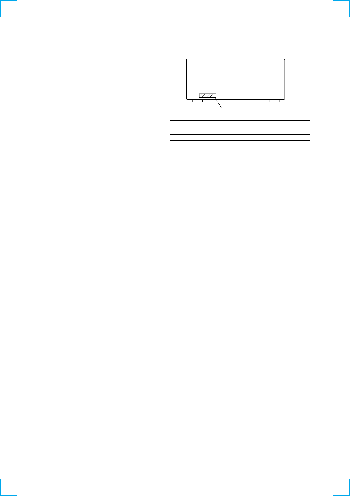
TABLE OF CONTENTS
1. SERVICE NOTE ............................................................... 3
2. GENERAL ......................................................................... 4
3. DISASSEMBLY
3-1. Case ..................................................................................... 5
3-2. Front Panel Assy ................................................................... 5
3-3. HP Board, Panel Board ......................................................... 6
4. DIAGRAMS
4-1. Block Diagram ...................................................................... 9
4-2. Printed Wiring Board – Main Section – .............................. 10
4-3. Schematic Diagram – Main Section – ................................ 11
4-4. Printed Wiring Board – Panel Section – ............................. 12
4-5. Schematic Diagram – Panel Section – ................................ 13
4-6. Printed Wiring Board – VOLSEL Section – ....................... 14
5. EXPLODED VIEWS
5-1. Case and Front Panel .......................................................... 15
6. ELECTRICAL PARTS LIST ........................................ 16
MODEL IDENTIFICATION
Parts No.
MODEL PARTS No.
AEP, AED, UK model 4-229-700-0s
MY, SP model 4-229-700-2s
HK model 4-229-700-3s
KR model 4-229-700-4s
• Abbreviation
AED : North European model
MY : Malaysia model
SP : Singapore model
HK : Hong Kong model
KR : Korea model
SAFETY-RELATED COMPONENT WARNING !!
COMPONENTS IDENTIFIED BY MARK 0 OR DOTTED LINE
WITH MARK 0 ON THE SCHEMATIC DIAGRAMS AND IN
THE PARTS LIST ARE CRITICAL TO SAFE OPERATION.
REPLACE THESE COMPONENTS WITH SONY PARTS
WHOSE PART NUMBERS APPEAR AS SHOWN IN THIS
MANUAL OR IN SUPPLEMENTS PUBLISHED BY SONY.
2

SECTION 1
SERVICING NOTE
This unit cannot be repaired by itself.
When repairing, connect the whole system except for the speaker.
CD Te xt Display
• This unit displays CD text.
Text is displayed for the first 50 track only and will not be displayed from the 51st track onwards. Do not suspect a fault in this case.
In some cases, some special characters will not be displayed and may be replaced by other characters. Do not suspect a fault in this case.
Cold Reset
• The cold reset clears all data including preset data stored in the RAM to initial conditions. Execute this mode when returning the set to the
customer.
Procedure :
1. When the power ON, press the ?/1 button (TA) while pressing the TUNING MODE button (ST) and ML buttons (CDP) together.
2. “COLD RESET” is displayed on the fluorescent indicator tube and reset is executed.
Hot Reset
• This mode reset the preset data kept in the memory. The hot reset mode functions same as if the power cord is plugged in and out.
Procedure :
1. When the power ON, press the ?/1 button (TA) while pressing the TUNING MODE button (ST) and lm buttons (CDP) together.
2. Turn off the unit and reset is executed.
GC Test Mode
Procedure :
1. When the power ON, press the ?/1 button (TA) while pressing the TUNING MODE button (ST) and PLAY MODE buttons (CDP)
together.
2. Fluorescent indicator tube are all turned on.
3. Press TUNING MODE button (ST) to enter the model destination indecation mode. “SP55 CE2” appears.
4. Every pressing of TUNING MODE button (ST) changes the display in the following order.
MC Version t CD Version t ST Version t TC Version t TA Version t TM Version t model destination display.
5. Press DISPLAY button (ST) and the date appears as “ 00615a ”
Every pressing of DISPLAY button (ST) changes the display in the Version display and model destination display.
6. Press TUNER/BAND button (ST) to enter the key check mode.
7. In the key check mode, the fluorescent indicator tube displays “Key 0 Vol 0”. Each time a button is pressed, “Key” value increases.
However, once a button is pressed, it is no longer taken into account.
“Vol” Value increases like “1, 2, 3 ...” if rotating VOLUME knob (TA) in the clockwise direction, or decreases like “0, 9, 8 ...” if rotating
in the counterclockwise diretion.
8. To exit from this mode, press three buttons in the same procedure as step 1, or disconnect the power cord.
MC Test Mode
Procedure :
1. When the power ON, press the ?/1 button (TA) while pressing TUNING MODE button (ST) and REPEAT button (CDP) together.
2. Frame of the MD mark and the CD mark flash, and “BASS/TRE FLAT” appears for a moment.
3. When the VOLUME knob (TA) is turned clockwise, “VOLUME MAX” appears for a moment.
4. When the VOLUME knob (TA) is turned counterclockwise, “VOLUME MIN” appears for a moment.
5. Select the function “TAPE” using the FUNCTION knob (TA).
Set the test tape AMS-110A or AMS-120.
6. Press DIRECTION button (TC) to enter either “j” (loop) or “h” (two way).
7. Press the CD SYNC REC button (TC) to start the AMS test.
(FWD) REW (Shut off)
(FWD) FF AMS
(FWD) REW AMS
END
8. Number of AMS signals is counted during the AMS test and the message “EDG#” (# means a number) appears. When the test tape
either AMS-110A or AMS-120 is used, the AMS signal is detected twice before shut off.
9. When the AMS test ends, either “OK” or “NG” appears.
10. To exit the MC test mode, either press the ?/1 button (TA)or perform the cold reset as described above.
(Shut off)
(Shut off)
3
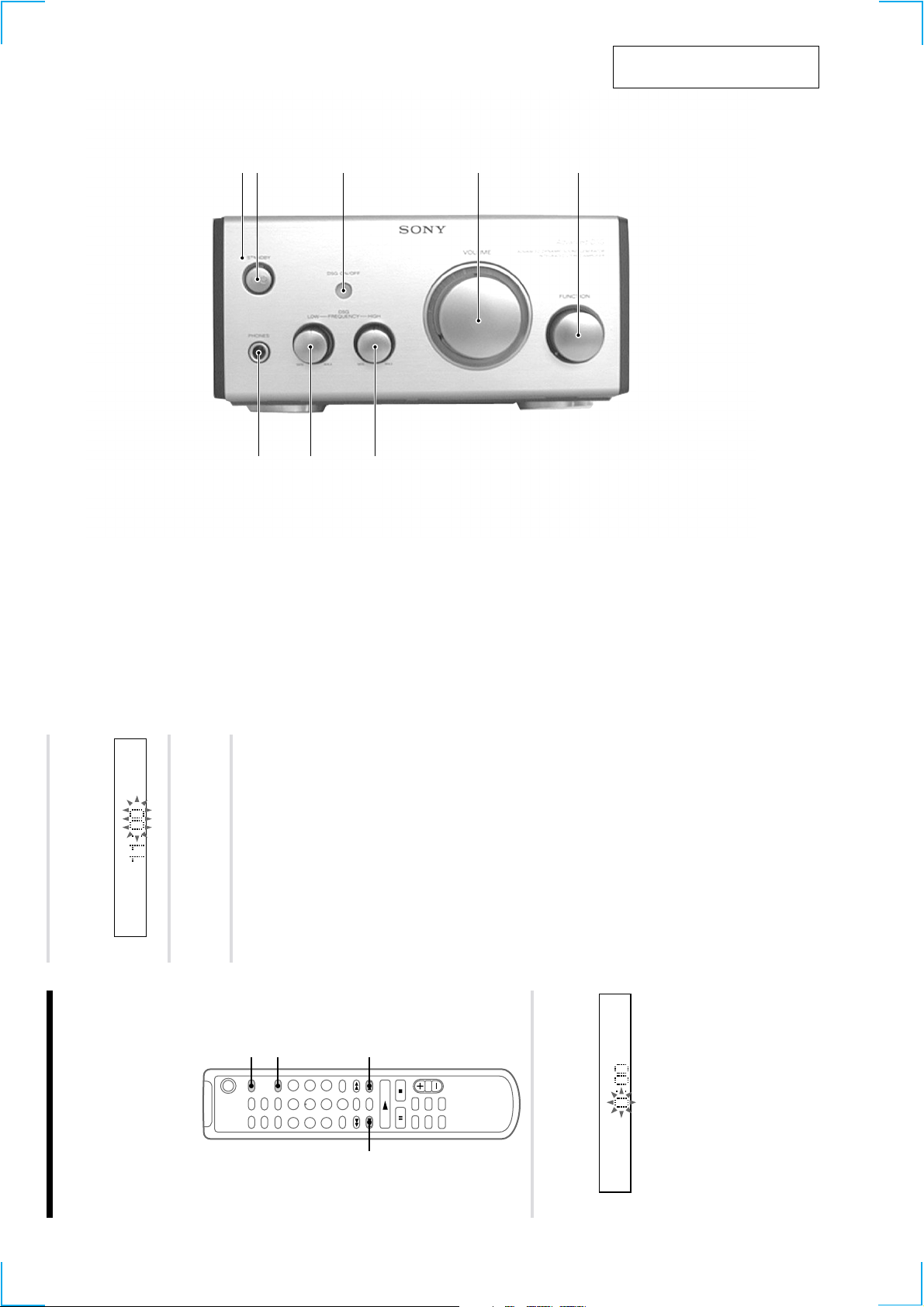
FRONT PANEL
SECTION 2
GENERAL
12 3 4 5
This section is extracted from
instruction manual.
8
1 STANDBY indicator
2 @/1 button
3 DSG ON/OFF button and indicator
4 VOLUME knob
5 FUNCTION knob
6 DSG FREQUENCY HIGH knob
7 DSG FREQUENCY LOW knob
8 PHONES jack
7 6
Press . or > to set the hour, then
The minute indication flashes.
press ENTER/YES.
2
Step 2: Setting the time
You must set the time beforehand to use the timer
functions.
The clock is on a 24-hour system for the European
Press . or > to set the minute,
The clock starts.
then press ENTER/YES.
3
`/1
model, and a 12-hour system for other models.
The 24-hour system is used for illustration
purposes.
Set the time before turning on the system.
4
If you made a mistake
Start over from step 1.
To change the preset time
You can change the preset time while the system
is on.
1 Press CLOCK/TIMER SET.
1
2,3
CLOCK” appears, then press ENTER/YES.
2 Press . or > repeatedly until “SET
3 Repeat steps 2 and 3.
Tips
the clock easier to see.
while the system is off. If you press DISPLAY at
this time, the display back light lights up, making
• The built-in clock shows the time in the display
seconds, and the lower dot flashes for the last 30
• The upper dot of the colon flashes for the first 30
2,32,3
seconds of each minute.
Press CLOCK/TIMER SET while the
system is off.
The hour indication flashes.
1
8
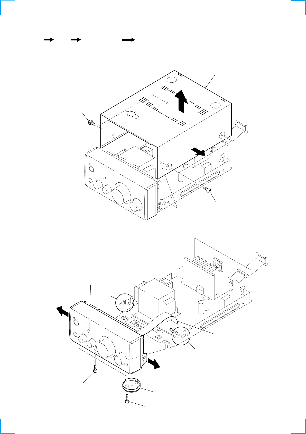
SECTION 3
DISASSEMBLY
Set Case Front Panel Assy
3-1. CASE
1 two screws
(case 3 TP2)
HP Board, Panel Board
4 case
3
2
2
3-2. FRONT PANEL ASSY
5 front panel assy
1 two screws
(case 3 TP2)
claws
1 flat type wire (17 core)
(CN303)
claws
4 screw (BVTP 3x12)
3 two foot assy's
2 two screws
(BVTP 3x12)
5
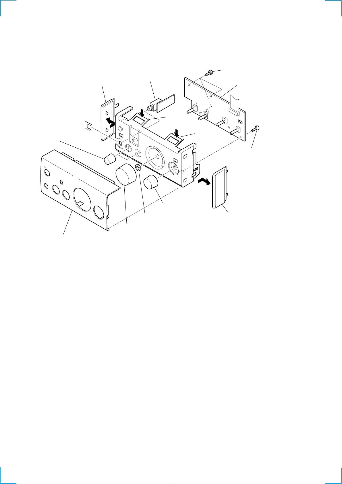
3-3. HP BOARD, PANEL BOARD
1 panel (L), side
5 HP board
0 three screws
(BVTP 2.6x8)
qa panel board
4
6 two knobs (DSG)
3 panel (TA), front
8 nut
7 knobs (VOL)
2 claw
2 claw
0 screw
(BVTP 2.6x8)
9 knobs (select)
1 panel (R), side
6
 Loading...