

Page 1
Video Cassette
Recorder
3-201-577-01 (1)
Operating Instructions
Mode d’emploi
Manual de Instrucciones
US
FR
ES
j
SVO-1330
1998 by Sony Corporation
Page 2
English
WARNING
To prevent fire or shock hazard, do not
expose the unit to rain or moisture.
This symbol is intended to alert the
user to the presence of uninsulated
“dangerous voltage” within the
product’s enclosure that may be of
sufficient magnitude to constitute a
risk of electric shock to persons.
This symbol is intended to alert the
user to the presence of important
operating and maintenance (servicing)
instructions in the literature
accompanying the appliance.
Caution
Television programs, films, video tapes and other materials
may be copyrighted. Unauthorized recording of such
material may be contrary to the provisions of the copyright
laws. Also, use of this recorder with cable television
transmission may require authorization from the cable
television transmission and/or program owner.
Owner’s record
The model number is located at the front of the unit and the
serial number on the rear. Record the serial number in the
space provided below. Refer to them whenever you call upon
your Sony dealer regarding this product.
Model No. SVO-1330 Serial No.
(FAROUDJA
logo)
This player has a Y/C filtering
technique incorporated under license
from Faroudja Laboratories Inc.
For the customers in the USA
This equipment has been tested and found to comply with
the limits for a Class B digital device, pursuant to Part 15 of
the FCC Rules. These limits are designed to provide
reasonable protection against harmful interference in a
residential installation. This equipment generates, uses, and
can radiate radio frequency energy and, if not installed and
used in accordance with the instructions, may cause harmful
interference to radio communications. However, there is no
guarantee that interference will not occur in a particular
installation. If this equipment does cause harmful
interference to radio or television reception, which can be
determined by turning the equipment off and on, the user is
encouraged to try to correct the interference by one or more
of the following measures:
• Reorient or relocate the receiving antenna.
• Increase the separation between the equipment and
receiver.
• Connect the equipment into an outlet on a circuit different
from that to which the receiver is connected.
• Consult the dealer or an experienced radio/TV technician
for help.
You are cautioned that any changes or modifications not
expressly approved in this manual could void your authority
to operate this equipment.
2 (US)
Page 3

Table of Contents
Overview
Setup
Precautions ................................................................4 (US)
Features......................................................................5 (US)
Location of Parts and Controls ................................6 (US)
Front panel .....................................................................6 (US)
Display window ............................................................. 7 (US)
Rear panel ...................................................................... 7 (US)
Connections...............................................................8 (US)
Basic connections...........................................................8 (US)
Connecting VCRs in series ............................................ 8 (US)
Setting the Language ................................................9 (US)
Setting the Clock ..................................................... 10 (US)
Setting the clock...........................................................10 (US)
Adjusting to Daylight Saving Time ............................. 11 (US)
Setting the Buzzers ................................................. 12 (US)
Basic Operations
Additional Operations
Recording.................................................................13 (US)
Recording ..................................................................... 13 (US)
Recording the date and time......................................... 14 (US)
Setting the timing of the tape-end alarm...................... 14 (US)
Setting the mode at the end of the tape ........................ 14 (US)
Monitoring the recording condition ............................. 15 (US)
Checking the tape threading......................................... 15 (US)
Checking the used time ................................................ 16 (US)
Locking the buttons on the VCR.................................. 16 (US)
Playing a Tape .......................................................... 17 (US)
Playing a tape ............................................................... 17 (US)
Playing/searching at various speeds............................. 17 (US)
Adjusting the Picture .............................................. 18 (US)
Adjusting the tracking.................................................. 18 (US)
Using the Adaptive Picture Control (APC).................. 18 (US)
Timer recording ....................................................... 19 (US)
Timer Recording .......................................................... 19 (US)
Checking/changing/cancelling timer settings .............. 21 (US)
Series Recording .....................................................22 (US)
Terminals..................................................................23 (US)
WARNING OUT terminal ........................................... 23 (US)
EJECT IN/OUT terminals............................................23 (US)
CLOCK ADJ IN/OUT terminals.................................. 24 (US)
REMOTE jack.............................................................. 25 (US)
CONTROL S IN/OUT jacks ........................................ 26 (US)
US
English
Others
Troubleshooting.......................................................27 (US)
Specifications .......................................................... 29 (US)
3 (US)
Page 4

Precautions
On safety
•Operate the unit on 120 V AC, 60 Hz only.
•The nameplate indicating operating voltage, power
consumption, etc., is located on the rear of the unit.
•If anything falls into the cabinet, unplug the unit and
have it checked by qualified personnel before
operating it any further.
•Do not drop or place heavy objects on the power
cord. If the power cord is damaged, turn off the
power immediately. It is dangerous to use the unit
with a damaged power cord.
•Unplug the unit from the wall outlet if you do not
intend to use it for an extended period of time. To
disconnect the cord, pull it out by the plug, never by
the cord.
On installation
•Allow adequate air circulation to prevent internal heat
buildup.
•Do not place the unit on surfaces (rugs, blankets, etc.)
or near materials (curtains, draperies) that may block
the ventilation slots.
•Do not install the unit near heat sources such as
radiators or air ducts, or in a place subject to direct
sunlight, excessive dust, mechanical vibration or
shock.
•Do not install the unit in an inclined position. It is
designed to be operated in a horizontal position only.
•Keep the unit and cassettes away from equipment
with strong magnets, such as microwave ovens or
large loudspeakers.
•Do not place heavy objects on the unit.
•If the unit is brought directly from a cold to a warm
location, moisture may condense inside the VCR and
cause damage to the video head and tape. When you
first install the unit, or when you move it from a cold
to a warm location, wait for about one hour before
operating the unit.
On video cassettes
Remove and store video cassettes after recording or
playback.
On cleaning
As a safety precaution, unplug the unit before cleaning
it.
•To keep the unit looking brand-new, periodically
clean it with a mild detergent solution. Never use
strong solvents such as thinner or benzine, or abrasive
cleaners since they will damage the cabinet.
When cleaning, keep liquid away from electrical
contacts and connectors.
•When there is a buildup of dust on air vents, use a
vacuum cleaner to remove it.
On repacking
•Before repacking, disconnect all cables and
connecting cords.
•Do not throw away the carton and packing materials.
They make an ideal container with which to transport
the unit. When shipping the unit to another location,
repack it.
On transportation
When transporting the unit, protect it from vibration
and impact.
If you have any questions about this unit, contact your
authorized Sony dealer.
4 (US)
Page 5

Features
•Timer recording function that enables you to record
at preset times, daily or weekly
•APC (Adaptive Picture Control) function that
automatically optimizes recording and playback
performance
•Recording checking function that enables you to
monitor the recorded image during recording
•Automatic switching to the daylight saving time
•Head counter that enables you to check the length of
time the video head has been used
•On-screen menu that displays information in three
languages (English, French or Spanish)
•Memory back-up function that, using a built-in
rechargeable battery, retains settings and adjustments
(including the clock) for up to 30 days when a power
interruption occurs
•Key inhibit function that locks the buttons on the
VCR
•CONTROL S IN/OUT jacks that offer remote control
of the tape operation with other Sony video
equipment
If you use the optional RM-V200 wired remote
control unit, you can control up to approximately 50
VCRs connected via CONTROL S IN/OUT in series.
•Series recording that allows recording on multiple
VCRs in sequence.
•Warning out terminal that outputs a signal when
trouble occurs during recording or the tape reaches its
end
•Eject in/out terminals that allow ejecting the tape
from multiple VCRs at the same time
•Clock adjust in/out terminals that allow clock
adjustment on multiple VCRs at the same time
Overview
5 (US)
Page 6
Location of Parts and Controls
Refer to the pages indicated in ( ) for details.
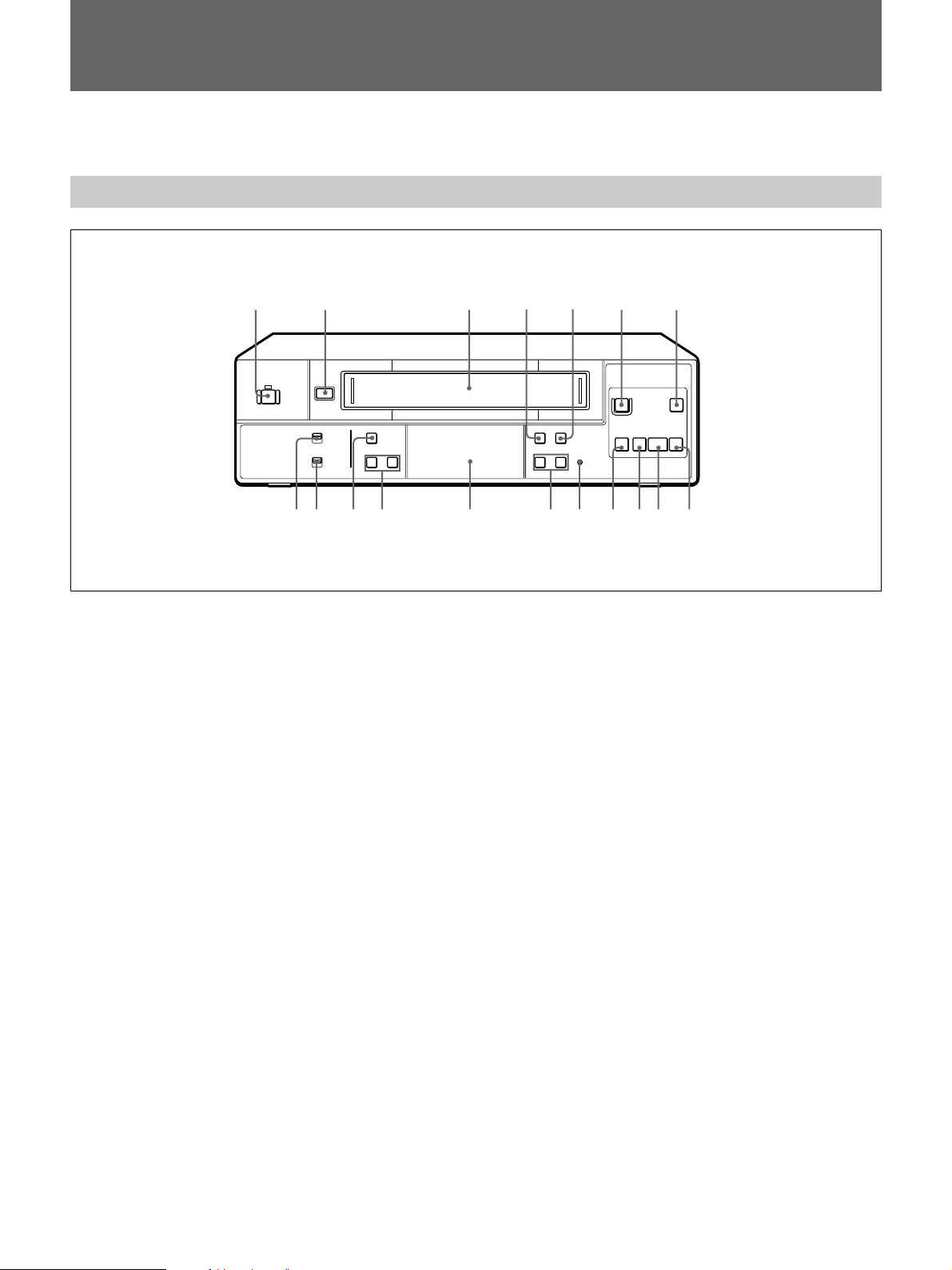
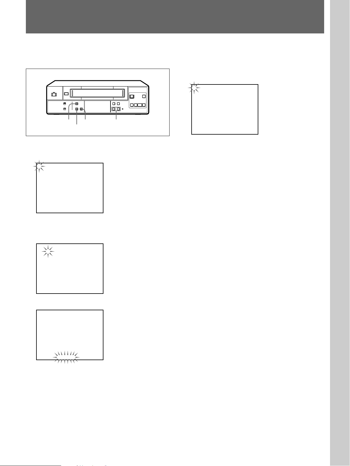
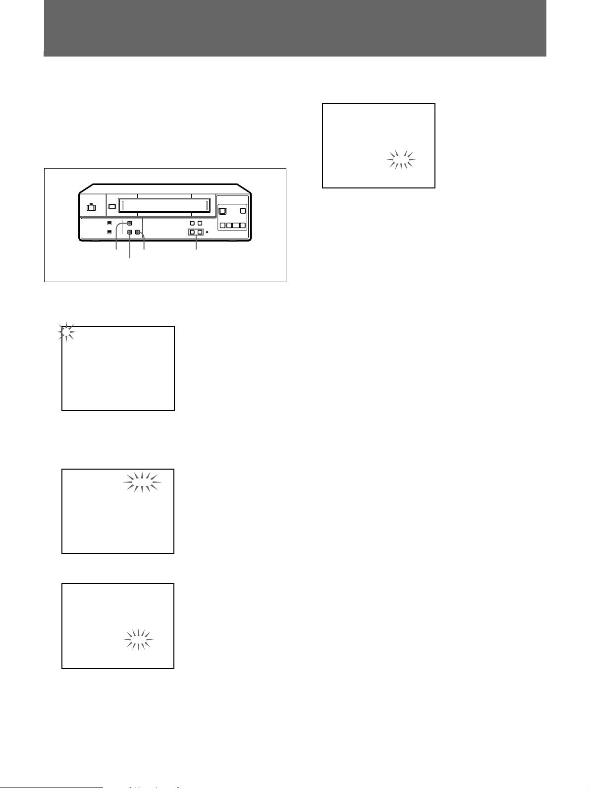
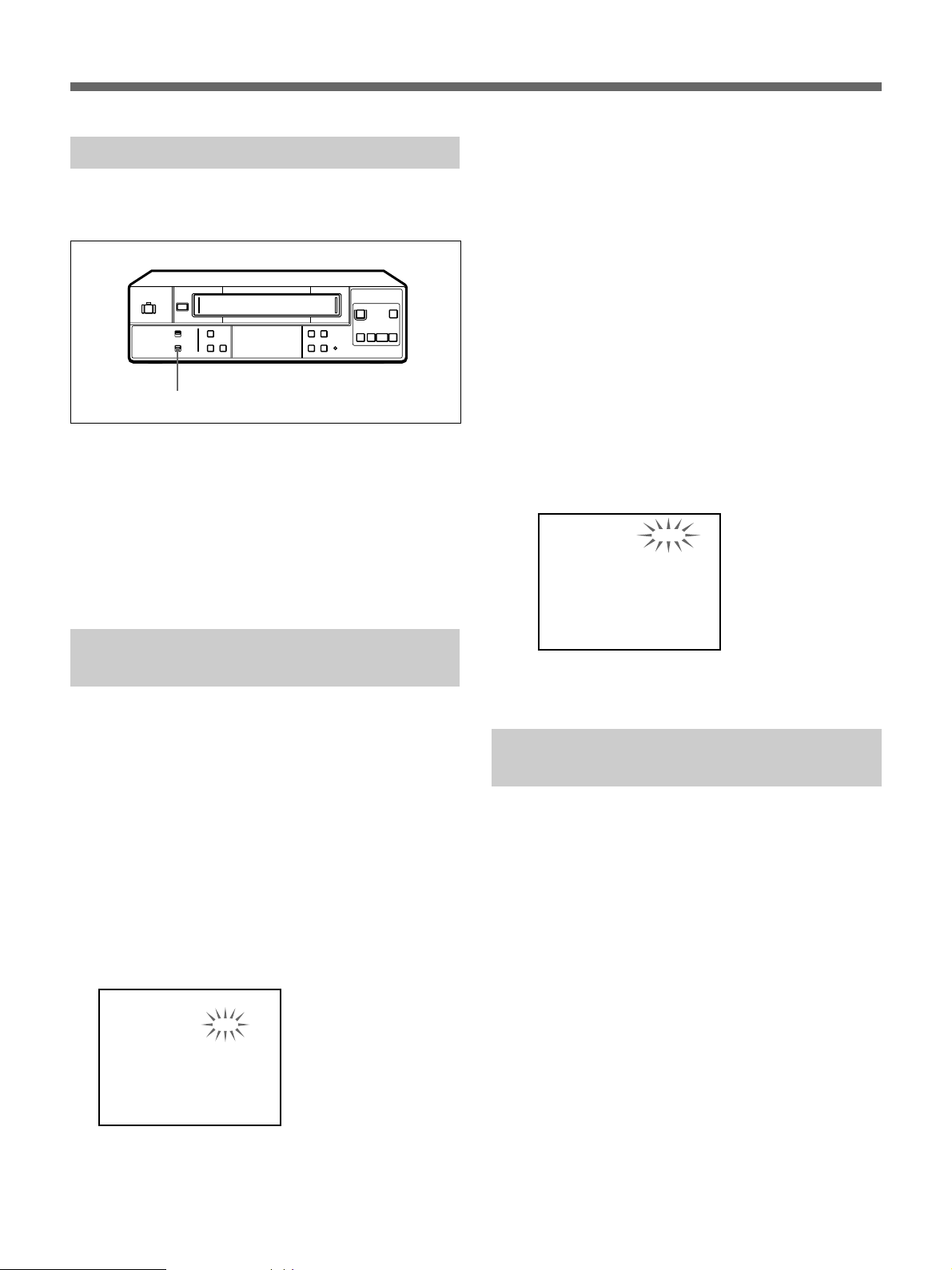
Front panel
1
2
6
1 POWER switch/indicator (13(US))
2 6 EJECT button (13
3 Cassette compartment (13
(US), 17(US))
(US))
4 TAPE SPEED (SP/EP) button (13
5 TIMER button (19
6 r REC button (13(
7 P PAUSE button (13
(US))
(US))
(US), 17(US))
8 ) FF (fast-forward) button (17
9 ( PLAY button (17
!º 0 REW (rewind) button (17
(US))
(US))
(US))
(US))
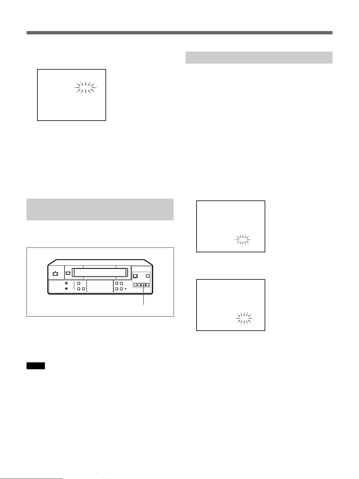
3
654
7
rP
p0()
8!™!∞ 9!§ !º!£ !¡!¶!• !¢
!¡ p STOP button (13
!™ RESET button (27
(US), 17(US))
(US))
!£ TRACKING/DATA +/– buttons (9
!¢ Display window (7
!∞ SHIFT v/b buttons (9
!§ MENU button (9
(US))
(US))
(US))
!¶ ON-SCREEN ON/OFF switch (14
!• KEY INHIBIT ON/OFF switch (16
(US), 18(US))
(US))
(US))
6 (US)
Page 7
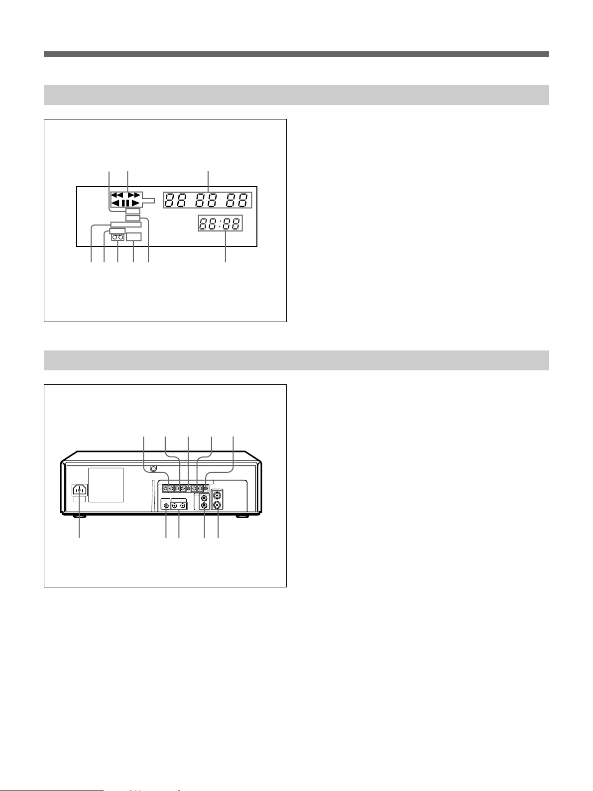
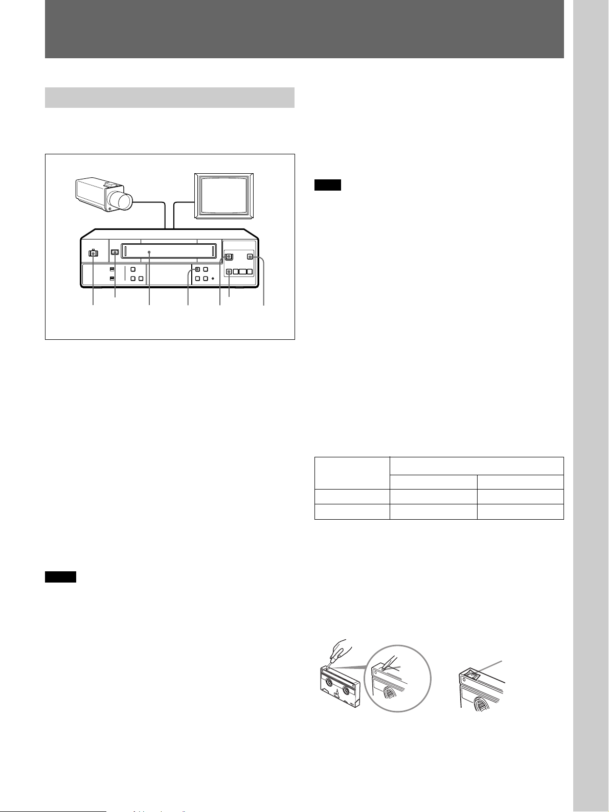
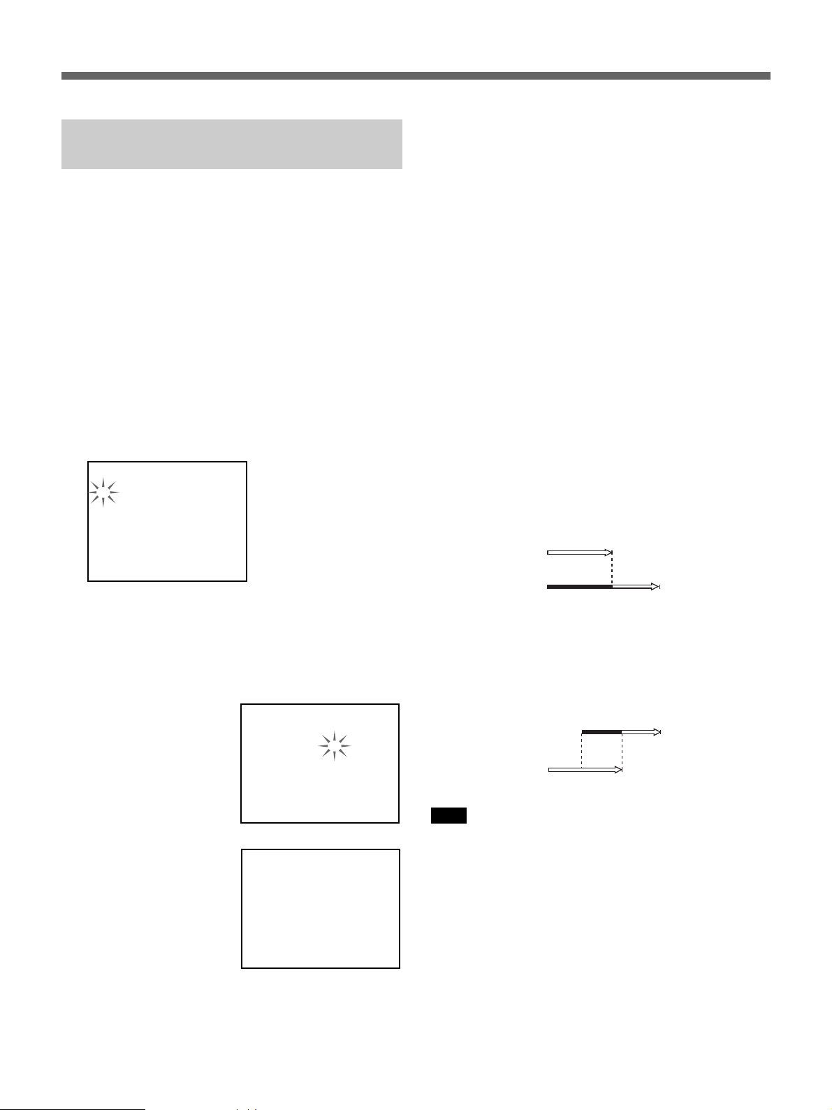
Display window
1
X 2
TIMER
REC
AUTO TRACKING
SP EP
KEY
INHIBIT
78
9
6
5
Rear panel
1 TIMER recording indicator
2 Tape operation indicators
3 Linear time counter
32
4 Clock
5 REC (recording) indicator
H M S
6 KEY INHIBIT indicator
7 Cassette in indicator
8 Tape speed indicators (SP/EP)
9 AUTO TRACKING indicator
4
123
4
1 CLOCK ADJ IN/OUT terminals (24(US))
2 SERIES REC IN/OUT terminals (8
5
3 GND terminal (8
4 EJECT IN/OUT terminals (23
(US), 23(US))
5 WARNING OUT terminal (23
6 VIDEO IN/OUT jacks (BNC type) (8
7 AUDIO IN/OUT jacks (phono type) (8
8 CONTROL S IN/OUT jacks (minijack) (26
9 REMOTE jack (stereo minijack) (25
67890
0 AC IN connector (8
(US))
(US))
(US))
(US))
(US))
(US))
(US))
(US))
7 (US)
Page 8
Connections
Before you get started...
•Turn off the power of all equipment.
•Do not connect the AC power cords until all of the
connections are completed.
•Be sure to make connections firmly. Loose
connections may cause picture distortion.
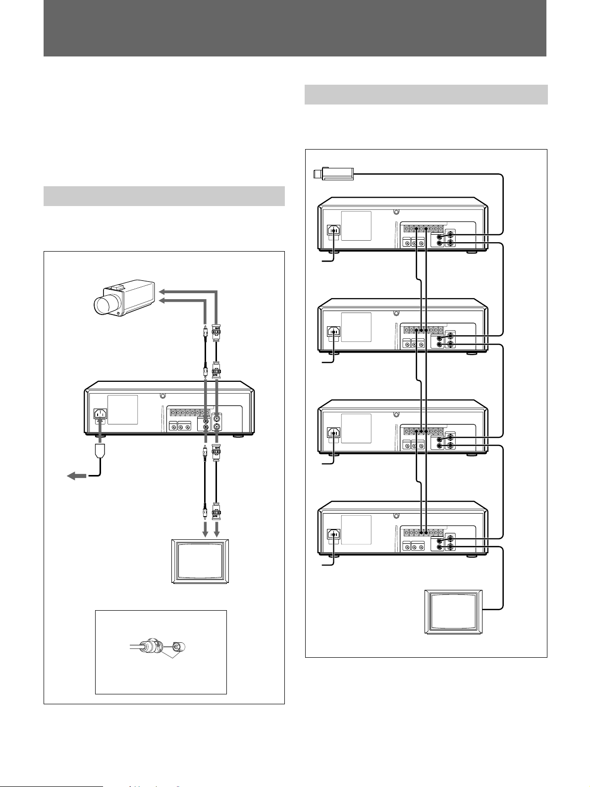
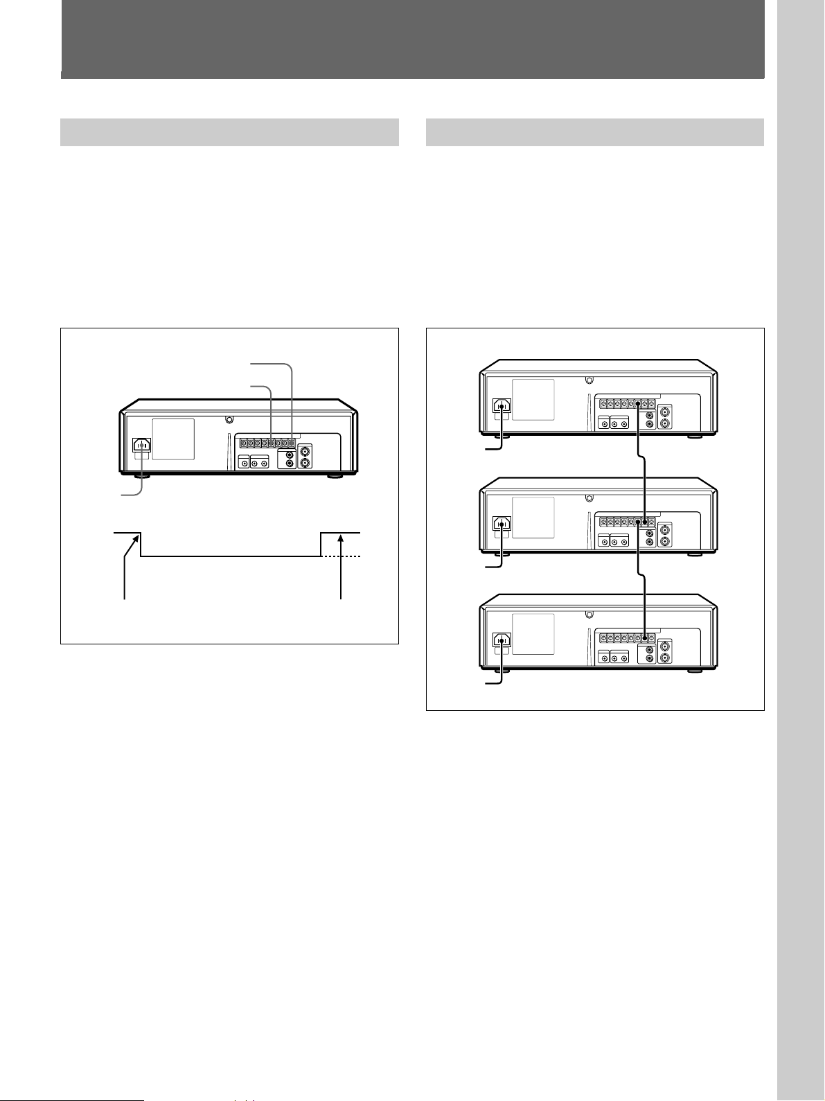
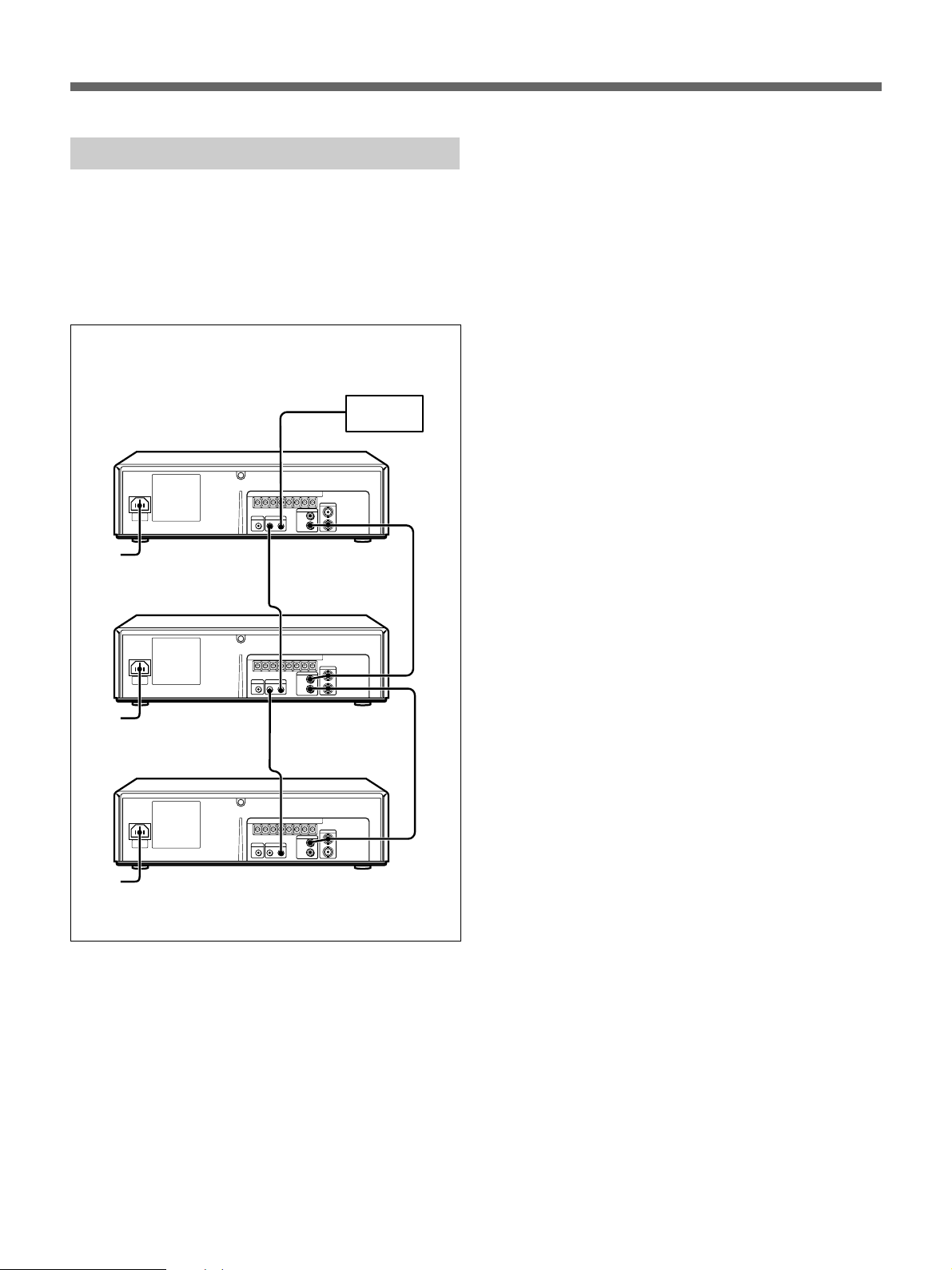
Basic connections
With the following connections, you can monitor the
picture and sound.
Video camera, etc.
to VIDEO OUT
to AUDIO
OUT
to AUDIO IN
to VIDEO IN
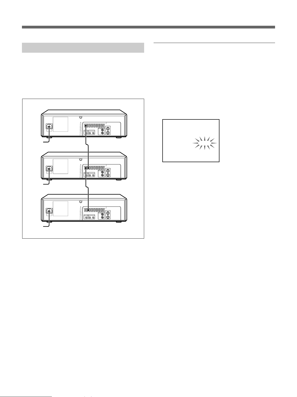
Connecting VCRs in series
With the following connection, you can perform a
series recording.
Video camera
VCR 1
to VIDEO/
AUDIO IN
to VIDEO/
AUDIO
OUT
to VIDEO/
AUDIO IN
to VIDEO/
AUDIO
OUT
VCR 2
to SERIES
REC OUT
to SERIES
REC IN
to SERIES
REC OUT
to GND
to GND
to GND
to a wall outlet
to AC IN
Use of BNC connector
Align pin with cutout, insert and
turn right to lock.
To remove, turn left and pull out.
to AUDIO
OUT
Audio cable
(not supplied)
Monitor
to VIDEO
OUT
Video cable
(not supplied)
to VIDEO INto AUDIO IN
VCR 3
VCR 4
to SERIES
REC IN
to SERIES
REC OUT
to SERIES
REC IN
to GND
to GND
to GND
Monitor
to VIDEO/
AUDIO IN
to VIDEO/
AUDIO
OUT
to VIDEO/
AUDIO IN
to VIDEO/
AUDIO
OUT
to VIDEO/
AUDIO IN
For operation of the series recording, see page 22(US).
8 (US)
Page 9
Setting the Language
1. AJUSTE RELOJ
HORA DE VERANO
IDIOMA
2. AJUSTE TEMPOR
3. AJUSTE
TIEMPO USADO
Setup
Select either English, French or Spanish for the onscreen menu language.
MENU
6
SHIFT b DATA +/–
SHIFT v
rP
p0()
1 Press MENU.
The main menu appears on the monitor screen.
1. CLOCK SET
DAYLIGHT SET
LANGUAGE
2. TIMER SET
3. SET UP
USED TIME
2 Make sure that 1.CLOCK SET /DAYLIGHT SET/
LANGUAGE is selected, and press SHIFT b.
The LANGUAGE menu appears.
[ CLOCK SET ]
01 - 01 - 00 00 : 00 : 00
[ DAYLIGHT SET ]
MODE NO USE
WEEK MONTH TIME
ON 1ST - SUN 04 02 : 00
OFF LST - SUN 10 02 : 00
4 Select the language: ENGLISH, FRANCAIS or
ESPANOL, using DATA +/–, then press MENU.
The main menu appears in the selected language.
Example: ESPANOL
5 Press MENU to return to the normal display.
[ LANGUAGE ]
ENGLISH
3 Press SHIFT v to flash the language.
[ CLOCK SET ]
01 - 01 - 00 00 : 00 : 00
[ DAYLIGHT SET ]
MODE NO USE
WEEK MONTH TIME
ON 1ST - SUN 04 02 : 00
OFF LST - SUN 10 02 : 00
[ LANGUAGE ]
ENGLISH
9 (US)
Page 10

Setting the Clock
[ CLOCK SET ]
[ LANGUAGE ]
ENGLISH
[ DAYLIGHT SET ]
MODE NO USE
OFF LST - SUN 10 02 : 00
ON 1ST - SUN 04 02 : 00
07 - 04 - 00 00 : 00 : 00
WEEK MONTH TIME
[ CLOCK SET ]
[ LANGUAGE ]
ENGLISH
[ DAYLIGHT SET ]
MODE NO USE
OFF LST - SUN 10 02 : 00
ON 1ST - SUN 04 02 : 00
07 - 04 - 99 00 : 00 : 00
WEEK MONTH TIME
[ CLOCK SET ]
[ LANGUAGE ]
ENGLISH
[ DAYLIGHT SET ]
MODE NO USE
OFF LST - SUN 10 02 : 00
ON 1ST - SUN 04 02 : 00
07 - 04 - 99 15 : 00 : 00
WEEK MONTH TIME
[ CLOCK SET ]
[ LANGUAGE ]
ENGLISH
[ DAYLIGHT SET ]
MODE NO USE
OFF LST - SUN 10 02 : 00
ON 1ST - SUN 04 02 : 00
07 - 04 - 99 15 : 00 : 00
WEEK MONTH TIME
Setting the clock
Set the clock to the current time and date to use the
timer feature of this VCR.
MENU
SHIFT v
6
SHIFT b DATA +/–
rP
p0()
1 Press MENU.
The main menu appears.
1. CLOCK SET
DAYLIGHT SET
LANGUAGE
2. TIMER SET
3. SET UP
USED TIME
Set the day using DATA +/–.
5 Press SHIFT b to flash the year.
Set the year using DATA +/–.
6 Press SHIFT b to flash the hour.
Set the hour using DATA +/–.
2 Make sure that 1.CLOCK SET /DAYLIGHT SET/
LANGUAGE is selected, and press SHIFT b.
The CLOCK SET menu appears on the screen and
the month flashes.
[ CLOCK SET ]
01 - 01 - 00 00 : 00 : 00
[ DAYLIGHT SET ]
MODE NO USE
WEEK MONTH TIME
ON 1ST - SUN 04 02 : 00
OFF LST - SUN 10 02 : 00
[ LANGUAGE ]
ENGLISH
3 Set the month using DATA +/–.
[ CLOCK SET ]
07 - 01 - 00 00 : 00 : 00
[ DAYLIGHT SET ]
MODE NO USE
WEEK MONTH TIME
ON 1ST - SUN 04 02 : 00
OFF LST - SUN 10 02 : 00
[ LANGUAGE ]
ENGLISH
4 Press SHIFT b to flash the day.
10 (US)
7 Press SHIFT b to flash the minutes.
Set the minutes using DATA +/–.
8 Press SHIFT b to flash the seconds.
Press DATA – simultaneously with a time signal.
The clock starts from 00 seconds.
9 Press MENU twice to return to the normal display.
Notes
•You cannot set the clock during timer recording or in
timer recording standby mode.
•To change or correct a setting, press SHIFT b to
flash the item you want to change and change the
setting.
Page 11

Adjusting to Daylight Saving Time
Adjust to Daylight Saving Time when the season
changes.
1 Display the DAYLIGHT SET menu.
Follow steps 1 and 2 in “Setting the clock” on
page 10(US).
[ CLOCK SET ]
07 - 04 - 99 15 : 00 : 00
[ DAYLIGHT SET ]
MODE NO USE
WEEK MONTH TIME
ON 1ST - SUN 04 02 : 00
OFF LST - SUN 10 02 : 00
[ LANGUAGE ]
ENGLISH
2 Press SHIFT v to flash the setting of “MODE.”
[ CLOCK SET ]
07 - 04 - 99 15 : 00 : 00
[ DAYLIGHT SET ]
MODE NO USE
WEEK MONTH TIME
ON 1ST - SUN 04 02 : 00
OFF LST - SUN 10 02 : 00
[ LANGUAGE ]
ENGLISH
4 Press SHIFT v, and set the date and time when the
Daylight Saving Time adjustment is to be made.
[ CLOCK SET ]
07 - 04 - 99 15 : 00 : 00
[ DAYLIGHT SET ]
MODE USE
WEEK MONTH TIME
ON 1ST - SUN 04 02 : 00
OFF LST - SUN 10 02 : 00
[ LANGUAGE ]
ENGLISH
WEEK ON
Set the week to make Daylight Saving Time
adjustment using DATA +/–: Select 1ST, 2ND,
3RD, 4TH or LST for the first, second, third,
fourth or last week.
Then press SHIFT b and set the day of the week
using DATA +/–: SUN, MON, ..., SAT.
MONTH ON
Press SHIFT b and set the month using DATA
+/–: 01, 02, ..., 12 for January, February, ...,
December.
TIME ON
Press SHIFT b and set the time using DATA +/
–. The time can only be set between 01 and 22.
Then press SHIFT b and set the minutes using
DATA +/–.
Daylight Saving Time
adjustment ON date and
time
Daylight Saving Time
adjustment OFF date and
time
3 Select USE using DATA +/– to make Daylight
Saving Time adjustment.
[ CLOCK SET ]
07 - 04 - 99 15 : 00 : 00
[ DAYLIGHT SET ]
MODE USE
WEEK MONTH TIME
ON 1ST - SUN 04 02 : 00
OFF LST - SUN 10 02 : 00
[ LANGUAGE ]
ENGLISH
Note
To correct settings, press SHIFT v and/or SHIFT
b to flash the setting you want to change, and
change the setting.
5 Press SHIFT v, and set the date and time to change
back to standard time in the same way.
6 Press MENU twice to return to the normal display.
11 (US)
Page 12
Setting the Buzzers
[ SET UP ]
[ USED TIME ]
HEAD 00005H
END ALARM
TAPE END
CLOCK ADJ
BUZZER
THREAD CHECK
TAPE
APC
T-120
END
REW
ON
0 1 : 0 0
OFF
ON
You can turn on/off the following buzzers.
•TAPE END buzzer: Beeps when the tape reaches
its end or the tape counter shows the reading set on
the “TAPE END” option in the SET UP menu.
•Warning buzzer: Beeps when the unit outputs a
warning signal from the WARNING OUT terminal.
MENU
SHIFT v
6
SHIFT b DATA +/–
rP
p0()
1 Press MENU.
The main menu appears.
1. CLOCK SET
DAYLIGHT SET
LANGUAGE
2. TIMER SET
3. SET UP
USED TIME
4 Set to ON or OFF using DATA +/–.
5 Press MENU twice to return to the normal display.
To stop the TAPE END buzzer
Press the p STOP button.
To stop the warning buzzer
Press one of the tape operation buttons (e.g. p STOP).
2 Press SHIFT v to select 3.SET UP/USED TIME,
then press SHIFT b.
The SET UP menu appears on the screen.
[ SET UP ]
TAPE
END ALARM
TAPE END
APC
CLOCK ADJ
BUZZER
THREAD CHECK
[ USED TIME ]
HEAD 00005H
3 Press SHIFT v to flash the setting of “BUZZER.”
[ SET UP ]
TAPE
END ALARM
TAPE END
APC
CLOCK ADJ
BUZZER
THREAD CHECK
[ USED TIME ]
HEAD 00005H
12 (US)
T-120
END
REW
ON
0 1 : 0 0
ON
ON
T-120
END
REW
ON
0 1 : 0 0
ON
ON
Page 13
Recording
Basic Operations
Recording
This section shows you how to record the signal from
the input sources connected to the VCR.
6
6 EJECT
1234
rP
p0()
p STOP
P PAUSE
1 Turn on the power of the equipment to be used.
2 Insert a tape with its safety tab in place.
The cassette in indicator flashes for about 5
seconds and the VCR checks the tape threading.
During this period, ( PLAY, r REC, ) FF
and 0 REW do not function.
For details, see “Checking the tape threading” on page
15(US).
3 Set the recording speed, SP (standard play) or EP
(extended play), by pressing TAPE SPEED.
See “To select tape speeds.”
To stop recording
Press p STOP.
To cut an unwanted scene while recording
Press P PAUSE, and press it again to resume
recording.
Note
When the recording pause mode lasts for more than
about 5 minutes, the VCR enters the stop mode.
To eject a tape
Press 6 EJECT.
You can eject the tape even when the power is off.
When you press 6 EJECT, the VCR turns on
automatically and turns off again after ejecting the
tape.
To select tape speeds
When recording, select either SP (standard play) or EP
(extended play) by pressing TAPE SPEED. EP
provides recording time three times as long as SP.
However, SP provides better picture quality. You can
mix SP and EP on the same tape. When playing a tape,
the VCR automatically detects the tape speed. See the
table below for the maximum recording/playback time
in each speed.
Tape type Maximum recording/playback time
SP EP
T-160 2 hrs. 40 min. 8 hrs.
T-120 2 hrs. 6 hrs.
4 Start recording by pressing r REC.
The REC indicator on the VCR lights up.
Notes
•If you insert a tape with its safety tab removed, the
VCR will eject it when you press r REC. To record
on this tape, cover the tab hole on the cassette with
adhesive tape.
•Whenever you insert a tape and first start recording,
Adaptive Picture Control (APC) automatically
improves recording quality by adjusting the VCR to
the condition of the video heads and tape. There is
about a 6-second delay before the VCR actually starts
recording when r REC is pressed.
See “Using the Adaptive Picture Control (APC)” on page
18(US) for details.
•If a power interruption occurs while recording, the
VCR will resume recording as soon as the power is
restored.
Saving a recording
Video tapes have a safety tab to protect against
accidental recording. To prevent accidental erasure of
a recording, break off the safety tab with a screwdriver
or other similar tool. A tape with its safety tab
removed is ejected if you try to record on it.
To record on this tape, simply cover the tab hole with
adhesive tape.
Safety
tab
Adhesive tape
13 (US)
Page 14
Recording
Recording the date and time
You can record the recording date and time on the tape
together with the picture.
6
ON SCREEN ON/OFF
rP
p0()
Set the ON SCREEN ON/OFF switch to ON. The
current date and time are displayed on the screen. If
you start recording in this condition, the displayed date
and time are recorded on the tape together with the
picture.
To turn off the date and time, set the ON SCREEN
ON/OFF switch to OFF.
Setting the timing of the tapeend alarm
END: An alarm signal is output when the tape
reaches its end.
02:00, etc.: An alarm signal is output when the
tape counter shows the set time (that is, the
nominal tape length in hours and minutes).
The time that appears depends on the setting of
“TAPE” and the recording tape speed (SP or
EP). Set the tape length correctly on “TAPE”
(T-120 or T-160).
When “TAPE” is set to T-120, 02:00 appears in
SP mode or 06:00 in EP mode;
When “TAPE” is set to T-160, 02:40 appears in
SP mode or 08:00 in EP mode.
4 Press SHIFT v to flash the setting of “TAPE” and
set it to T-120 or T-160 using DATA +/–.
(You may skip this step if you set “END ALARM”
to END in step 3.)
[ SET UP ]
TAPE
END ALARM
TAPE END
APC
CLOCK ADJ
BUZZER
THREAD CHECK
[ USED TIME ]
HEAD 00005H
T-160
0 2 : 4 0
REW
ON
0 1 : 0 0
ON
ON
5 Press MENU twice to return to the normal display.
You can select the timing at which the TAPE END
buzzer beeps to indicate the tape reaches its end or the
nominal tape length (before its end).
1 Press MENU and select 3.SET UP/USED TIME
using SHIFT v, then press SHIFT b.
The SET UP menu appears on the screen.
2 Press SHIFT v to flash the setting of “END
ALARM.”
3 Set “END ALARM” to END or 02:00 for example
(nominal tape length), using DATA +/–.
[ SET UP ]
TAPE
END ALARM
TAPE END
APC
CLOCK ADJ
BUZZER
THREAD CHECK
[ USED TIME ]
HEAD 00005H
T-120
END
REW
ON
0 1 : 0 0
ON
ON
Setting the mode at the end of the tape
You can rewind or eject the tape when it comes to the
end during recording.
1 Press MENU and select 3.SET UP/USED TIME
using SHIFT v, then press SHIFT b.
The SET UP menu appears on the screen.
2 Press SHIFT v to flash the setting of “TAPE
END.”
14 (US)
Page 15
3 Set “TAPE END” to REW or EJECT using DATA
[ SET UP ]
[ USED TIME ]
HEAD 00005H
END ALARM
TAPE END
CLOCK ADJ
BUZZER
THREAD CHECK
TAPE
APC
T-120
END
REW
ON
0 1 : 0 0
OFF
ON
[ SET UP ]
[ USED TIME ]
HEAD 00005H
END ALARM
TAPE END
CLOCK ADJ
BUZZER
THREAD CHECK
TAPE
APC
T-120
END
REW
ON
0 1 : 0 0
OFF
OFF
+/–.
[ SET UP ]
TAPE
END ALARM
TAPE END
APC
CLOCK ADJ
BUZZER
THREAD CHECK
[ USED TIME ]
HEAD 00005H
T-120
END
REW
ON
0 1 : 0 0
ON
ON
REW: when the tape comes to the end, the VCR
rewinds the tape automatically and enters stop
mode at the beginning of the tape.
EJECT: when the tape comes to the end, the tape
is ejected automatically.
4 Press MENU twice to return to the normal display.
Monitoring the recording condition
Checking the tape threading
To ensure correct operation, the VCR checks
automatically the tape threading whenever you insert a
tape, and it takes about 5 seconds. If an error is
detected, the VCR ejects the tape.
During this period, tape operation buttons such as (
PLAY, r REC, ) FF and 0 REW do not
function.
If you consider it unnecessary to check the tape
threading, you can cancel it in the SET UP menu.
1 Press MENU and select 3.SET UP/USED TIME
using SHIFT v, then press SHIFT b.
The SET UP menu appears on the screen.
2 Press SHIFT v to flash the setting of “THREAD
CHECK.”
You can check the recording condition by pressing
(PLAY while recording.
6
rP
p0()
(PLAY
Press (PLAY while recording.
After the tape is rewound for about three seconds and
played back for about two seconds, the unit returns to
the original recording mode.
Notes
•While monitoring the recording condition, recording
is interrupted.
•When the recording is not performed correctly, an
alarm signal is output from the WARNING OUT
terminal.
3 Set to OFF to cancel the tape threading check
using DATA +/–.
4 Press MENU twice to return to the normal display.
15 (US)
Page 16

Recording
Checking the used time
You can check the length of time the video head has
been used in the USED TIME menu.
1 Press SHIFT v to select 3.SET UP/USED TIME,
then press SHIFT b.
The SET UP menu appears on the screen.
2 Check the head counter.
[ SET UP ]
TAPE
END ALARM
TAPE END
APC
CLOCK ADJ
BUZZER
THREAD CHECK
[ USED TIME ]
HEAD 00005H
T-120
END
REW
ON
0 1 : 0 0
ON
ON
Head counter
3 Press MENU twice to return to the normal display.
Locking the buttons on the VCR
You can lock the buttons on the VCR. This is
convenient if you want to prevent accidental
operations while controlling this VCR with a wired
remote control unit (not supplied). It is also convenient
when you use this VCR in a public place; this protects
the VCR from mishaps caused by other people
touching it.
6
KEY INHIBIT ON/OFF
rP
p0()
Set the KEY INHIBIT ON/OFF switch on the VCR to
ON.
“KEY INHIBIT” appears in the VCR’s display
window and the buttons on the VCR are locked.
To resume normal operation, set the KEY INHIBIT
ON/OFF switch to OFF.
16 (US)
Page 17

Playing a Tape
Playing a tape
This section shows you how to play a video tape.
23
6 EJECT
6
p STOP
0 REW ) FF
rP
p0()
P PAUSE
1 Turn on the power of the equipment to be used.
2 Insert a tape.
The VCR turns on automatically.
The cassette in indicator flashes for about 5
seconds and the VCR checks the tape threading.
During this period, ( PLAY, r REC, ) FF
and 0 REW do not function.
For details, see “Checking the tape threading” on page
15(US).
3 Press ( PLAY to start playing.
Additional tasks
To Press
Stop play p STOP
Fast-forward the tape ) FF during stop
Rewind the tape 0 REW during stop
Eject the tape 6 EJECT
For further information on searching and playback
functions, see “Playing/searching at various speeds.”
Playing/searching at various speeds
You can play back a tape at various speeds: highspeed, still, slow and so on. These options are also
useful for searching for a specific point during
playback. The sound is muted during these operations.
Picture search
During playback, hold down ) FF (forward
direction) or 0 REW (reverse direction). A highspeed picture appears on the monitor screen. To
resume normal playback, release ) FF or 0
REW.
Note
During picture search, streaks or noise appear on the
monitor screen.
Still picture
During playback, press P PAUSE.
To resume normal playback, press ( PLAY.
When the still mode lasts for more than approximately
5 minutes, the VCR will automatically resume the
playback mode.
If the picture shakes in the still mode
Adjust the picture with TRACKING/DATA +/–.
Slow-motion picture
In the still mode, press P PAUSE again to get a slowmotion picture at one-fifth the normal speed. By
pressing P PAUSE again, the still mode resumes.
To resume normal playback, press ( PLAY.
17 (US)
Page 18

Adjusting the Picture
[ SET UP ]
[ USED TIME ]
HEAD 00005H
END ALARM
TAPE END
CLOCK ADJ
BUZZER
THREAD CHECK
TAPE
APC
T-120
END
REW
ON
0 1 : 0 0
ON
ON
Adjusting the tracking
Though the VCR automatically adjusts the tracking
when playing a tape (the AUTO TRACKING indicator
flashes in the display window, then lights steadily),
distortion may occur if the tape was recorded in poor
condition. If so, manually adjust the tracking
condition.
6
AUTO TRACKING
indicator
TRACKING/DATA +/–
rP
p0()
Press TRACKING/DATA +/–. (The AUTO
TRACKING indicator goes off.) The distortion should
disappear as you press one of the two buttons.
To return to the automatic tracking adjustment, press
TRACKING/DATA + and – simultaneously.
Using the Adaptive Picture Control (APC)
Adaptive Picture Control (APC) automatically
improves recording and playback quality by adjusting
the VCR to the condition of the video heads and tape.
To maintain better picture quality, it is recommended
to set “APC” to ON in the SET UP menu.
2 Press SHIFT v to flash the setting of “APC.”
3 Set to ON to use APC function using DATA +/–.
4 Press MENU twice to return to the normal display.
To use APC during playback
The APC function automatically works on all types of
tapes. You can play a tape using the APC function
even if the tape was not recorded with it.
To use APC while recording
Whenever you insert a tape and first start recording,
the VCR adjusts to the tape using the APC function.
This adjustment is retained until the tape is ejected.
There is a short delay before the VCR actually starts
recording while the VCR analyzes the tape.
Note
When the APC function does not work properly due to
a video head clogging or other reasons, an alarm signal
is output from the WARNING OUT terminal. While
recording, the REC indicator flashes in the display
window, but the recording continues even in this
condition.
1 Press MENU and select 3.SET UP/USED TIME
using SHIFT v, then press SHIFT b.
The SET UP menu appears.
[ SET UP ]
TAPE
END ALARM
TAPE END
APC
CLOCK ADJ
BUZZER
THREAD CHECK
[ USED TIME ]
HEAD 00005H
18 (US)
T-120
END
REW
ON
0 1 : 0 0
ON
ON
Page 19

Timer Recording
[ TIMER SET ]
1 0 1 3:– – – –:– – EP
– – – –:– – – –:– – – –
– – – –:– – – –:– – – –
– – – –:– – – –:– – – –
– – – –:– – – –:– – – –
– – – –:– – – –:– – – –
– – – –:– – – –:– – – –
– – – –:– – – –:– – – –
DATE START STOP MODE
[ TIMER SET ]
1 0 1 3:1 5 – –:– – EP
– – – –:– – – –:– – – –
– – – –:– – – –:– – – –
– – – –:– – – –:– – – –
– – – –:– – – –:– – – –
– – – –:– – – –:– – – –
– – – –:– – – –:– – – –
– – – –:– – – –:– – – –
DATE START STOP MODE
[ TIMER SET ]
1 0 1 3:1 5 1 4:0 0 EP
– – – –:– – – –:– – – –
– – – –:– – – –:– – – –
– – – –:– – – –:– – – –
– – – –:– – – –:– – – –
– – – –:– – – –:– – – –
– – – –:– – – –:– – – –
– – – –:– – – –:– – – –
DATE START STOP MODE
Timer recording
This section shows you how to let the VCR
automatically start and stop recording a program. You
can preset up to 8 programs for timer recording.
Before you start...
•Check that the clock is set correctly.
•For timer recording, insert a tape with its safety tab in
place. Make sure the tape is longer than the total
recording time you are programming.
•Turn on the power of the equipment to be used.
6
MENU DATA +/–
SHIFT v TIMER
SHIFT b
rP
p0()
1 Press MENU and select 2.TIMER SET using
SHIFT v, then press SHIFT b.
The TIMER SET menu appears and today’s date
flashes.
3 Press SHIFT b and set the time to start recording
using DATA +/–:
Press SHIFT b to flash the hour under “START, ”
then set the hour using DATA +/–.
Press SHIFT b to flash the minutes under
“START,” then set the minutes using DATA +/–.
4 Press SHIFT b, then set the time to stop recording
in the same way using DATA +/–.
[ TIMER SET ]
DATE START STOP MODE
0 4 – –:– – – –:– – EP
– – – –:– – – –:– – – –
– – – –:– – – –:– – – –
– – – –:– – – –:– – – –
– – – –:– – – –:– – – –
– – – –:– – – –:– – – –
– – – –:– – – –:– – – –
– – – –:– – – –:– – – –
2 Set the “DATE” to start recording using DATA+/–.
[ TIMER SET ]
DATE START STOP MODE
1 0 – –:– – – –:– – EP
– – – –:– – – –:– – – –
– – – –:– – – –:– – – –
– – – –:– – – –:– – – –
– – – –:– – – –:– – – –
– – – –:– – – –:– – – –
– – – –:– – – –:– – – –
– – – –:– – – –:– – – –
Note
You can preset the date within a one-month time
frame only, except for daily/weekly recording,
which remains effective until changed.
To record the same program every day or every week,
see “Daily/weekly recording” on page 20(US).
5 Press SHIFT b and set the tape speed (SP or EP)
using DATA +/–.
Refer to page 13(US) for details on tape speeds.
[ TIMER SET ]
DATE START STOP MODE
1 0 1 3:1 5 1 4:0 0 SP
– – – –:– – – –:– – – –
– – – –:– – – –:– – – –
– – – –:– – – –:– – – –
– – – –:– – – –:– – – –
– – – –:– – – –:– – – –
– – – –:– – – –:– – – –
– – – –:– – – –:– – – –
To preset another timer setting, press SHIFT v to
flash the date of the next line, and repeat steps 2 to
5.
To correct settings, press SHIFT v and SHIFT b to
flash the setting you want to change, and change it.
(continued)
19 (US)
Page 20

Timer Recording
6 After completing the settings, press MENU twice,
then press TIMER.
The TIMER indicator lights up in the display
window and the VCR turns off and stands by for
recording.
The VCR automatically turns on and starts
recording 15 seconds before the preset start time.
Notes
• The TIMER indicator flashes if you set the start
time within 5 minutes.
• If you insert a tape with its safety tab removed,
the VCR will eject it at the preset start time for
timer recording.
To stop timer recording
To stop the tape during timer recording, press TIMER
to turn off the TIMER indicator in the display window.
If a power interruption occurs
•If a power interruption occurs during timer recording,
and if the preset stop time is not over when the power
is restored, the VCR will resume timer recording.
•Even if a power interruption occurs during timer
recording standby, the setting is effective until the
preset stop time is over. If the power is restored
during the preset time, the VCR starts recording
immediately.
Each time DATA – is pressed, the setting changes as
follows:
4 (today) n SAT (every Saturday) n FRI n THU
n WED n TUE n MON n SUN n MO-FR
(Monday to Friday) n MO-SA (Monday to Saturday)
n MO-SU (every day)
Using the VCR before timer recording begins
Press TIMER to turn off the TIMER indicator in the
display window, then press POWER.
The VCR is ready for use.
After using the VCR, press TIMER again to turn on
the TIMER indicator in the display window.
About warning beep
A warning beep sounds in the following cases:
•If you press TIMER when
– no program is set for timer recording
– no cassette has been inserted
•If you try to change the timer program during timer
recording
•If you try to reset the clock during timer recording
•If you try to set for timer recording when the clock
has not been set
Daily/weekly recording
You can preset the VCR to record the same program
every day of the week (daily recording) or the same
program on the same day every week (weekly
recording). Press DATA – in step 2 on page 19(US)
until the desired setting appears in the DATE position.
20 (US)
Page 21
Checking/changing/cancelling
10:00
10:50
11:30
timer settings
This section shows you how to check, change and
cancel the timer settings after you have stored them in
the VCR.
Before you start...
Turn on your monitor.
1 Press TIMER to turn off the TIMER indicator in
the display window.
2 Press POWER to turn on the VCR.
6 Press MENU twice.
The VCR returns to the original screen. When
there are any other timer settings left in the TIMER
SET menu, press TIMER to return to recording
standby.
To check the timer settings during timer
recording
Press MENU and select 2. TIMER SET. After
checking, press MENU twice to turn off the display.
When the timer settings overlap
The VCR will not record overlapping programs. If any
of your timer settings overlap, change the settings.
3 Press MENU and select 2. TIMER SET using
SHIFT v, then press SHIFT b.
The TIMER SET menu appears.
[ TIMER SET ]
DATE START STOP MODE
1 0 1 3:1 5 1 4:0 0 SP
MON 0 2:0 0 0 3:0 0 SP
0 4 1 1:0 0 1 1:5 0 SP
MO-SA
0 9:0 0 1 0:3 0 EP
– – – –:– – – –:– – – –
– – – –:– – – –:– – – –
– – – –:– – – –:– – – –
– – – –:– – – –:– – – –
4 Check the timer settings:
If you do not need to change or cancel the settings,
press MENU twice, then press TIMER to return to
recording standby.
5 Change or cancel the timer setting:
• To change the setting,
press SHIFT v and
SHIFT b to flash the
item you want to
change, and reset it
using DATA +/–.
• To cancel the setting,
press SHIFT v and
SHIFT b to flash the
“MODE” setting of
the program you want
to cancel, then set it to
“– –” using DATA +/
–. By pressing SHIFT
v, the program is
cancelled.
[ TIMER SET ]
DATE START STOP MODE
1 0 1 3:1 5 1 4:0 0 SP
MON 0 2:0 0 0 4:0 0 SP
0 4 1 1:0 0 1 1:5 0 SP
MO-SA
0 9:0 0 1 0:3 0 EP
– – – –:– – – –:– – – –
– – – –:– – – –:– – – –
– – – –:– – – –:– – – –
– – – –:– – – –:– – – –
[ TIMER SET ]
DATE START STOP MODE
1 0 1 3:1 5 1 4:0 0 SP
MON 0 2:0 0 0 3:0 0 SP
– – – –:– – – –:– – – –
MO-SA
0 9:0 0 1 0:3 0 EP
– – – –:– – – –:– – – –
– – – –:– – – –:– – – –
– – – –:– – – –:– – – –
– – – –:– – – –:– – – –
Case 1: If you preset two programs to start
recording at the same time...
The program listed first in the TIMER SET menu has
priority over the other programs. The timer settings of
lower priority programs will start recording when the
VCR stops recording the higher priority program.
Case 1
Program 1
(listed first)
Program 2
(listed next)
Will be
cut off
Case 2: If you preset program 1 to start recording
before program 2 is finished recording...
Program 1 will start recording after program 2 has
finished.
Case 2
Program 1
Program 2
Note
10:00
10:30
11:30
Will be
cut off
11:00
The VCR starts recording 15 seconds before the preset
start time.
About memory back-up function
The VCR has a memory back-up function. Even if the
power is interrupted, settings and adjustments are
retained for up to 30 days using the built-in
rechargeable battery.
21 (US)
Page 22

Series Recording
When you connect multiple SVO-1330 VCRs in
series, you can start recording on one VCR
automatically when the tape on another VCR reaches
the end.
For connections, see “Connecting VCRs in series” on page
8(US).
Before you start...
•Insert a tape with its safety tab in place into each
VCR.
•Make sure that the TIMER indicator is turned off on
each VCR.
•Set the recording speed, SP (standard play) or EP
(extended play), correctly on each VCR.
VCR 1
6
2
6
POWER OFF
rP
p0()
3
VCR 2
rP
p0()
1 Turn on the power of the equipment to be used.
2 Turn on the power of VCR 1, and turn off the
power of VCR 2 and subsequent VCRs.
3 Start recording on VCR 1.
The REC indicator on VCR 1 lights up.
22 (US)
Page 23
Terminals
Additional Operations
WARNING OUT terminal
The VCR outputs a signal from the WARNING OUT
terminal when something wrong has happened to the
VCR during recording:
– when the recording stops due to an entangled tape
– when the APC detects an improper video signal
level at the start of recording
– when an improper video signal level is detected by
the recording checking function
WARNING OUT terminal
GND terminal
REC mode
Output
signal
Recording stops.
To reset, press one of the
tape operation buttons.
5 V
0 V
EJECT IN/OUT terminals
If you connect the EJECT IN/OUT terminals of the
VCRs, you can eject the tape inserted into all the
connected VCRs simultaneously in the following
cases:
– when you press 6 EJECT of VCR 1
– when you press the EJECT buttons on the RM-
V200 Remote Control Unit (not supplied)
– when you input a signal from an external switch
VCR 1
to EJECT OUT
VCR 2
to EJECT OUT
VCR 3
to EJECT IN
to EJECT IN
When using the RM-V200 Remote Control Unit
Connect the RM-V200 to the CONTROL S IN jack of
VCR 1, and connect the VCRs via the CONTROL S
IN and OUT jacks.
For connecting the CONTROL S IN and OUT jacks, see
page 26(US).
When using an external switch
Connect the external switch between the EJECT IN
terminal and the GND terminal of VCR 1.
23 (US)
Page 24
Terminals
CLOCK ADJ IN/OUT terminals
If you connect the CLOCK ADJ IN/OUT terminals of
the VCRs, you can adjust the clock of all the connected
VCRs simultaneously in the following cases:
– when the clock of VCR 1 comes to the set time
– when you input a signal from an external switch
VCR 1
to CLOCK ADJ OUT
VCR 2
to CLOCK ADJ OUT
VCR 3
to CLOCK ADJ IN
to CLOCK ADJ IN
Setting the clock adjustment time
1 Press MENU and select 3.SET UP/USED TIME
using SHIFT v, then press SHIFT b.
The SET UP menu appears on the screen.
2 Press SHIFT v to flash the setting of “CLOCK
ADJ.”
3 Set the time you want to adjust the clock using
DATA +/–.
[ SET UP ]
TAPE
END ALARM
TAPE END
APC
CLOCK ADJ
BUZZER
THREAD CHECK
[ USED TIME ]
HEAD 00005H
When using the clock of VCR 1:
When the clock of VCR 1 comes to the time set
on “CLOCK ADJ,” the signal will be output
from the CLOCK ADJ OUT terminal to adjust
the clocks of all the connected VCRs.
When using an external switch:
When you turn on the switch and its signal is
received at the CLOCK ADJ IN terminal of
VCR 1, the clocks of all the connected VCRs
will be adjusted to the time set on “CLOCK
ADJ.”
T-120
END
REW
ON
0 1 : 0 0
ON
ON
When using an external switch
Connect the external switch between the CLOCK ADJ
IN terminal and the GND terminal of VCR 1.
24 (US)
4 Press MENU twice to return to the normal display.
Page 25

REMOTE jack
Using recording status output signal
This VCR can be remotely controlled by adding the
circuit shown below to the REMOTE jack or by using
the SVT-RM10 Remote Control Unit (not supplied).
REMOTE jack
R2
R3
R4
R5
R6
R7
R8
R9
R10
R11
R12
R13
1.5K
0.43K
0.51K
0.62K
0.75K
0.91K
1.1K
1.3K
2.0K
2.4K
3.6K
5.6K
SW1 ......... STOP
SW2 ......... PAUSE
SW3 ......... REW
SW4 ......... FF
SW5 ......... PLAY
SW6 ......... REC
SW7 ......... MENU
SW8 ......... REV PLAY
SW9 ......... TRACKING/DATA –
SW10 ....... TRACKING/DATA +
SW11 ....... SHIFT v
SW12 ....... SHIFT b
Resistor tolerance should be equal
to or less than ±2%.
SW1
SW2
SW3
SW4
SW5
SW6
SW7
SW8
SW9
SW10
SW11
SW12
Note
Use a shielded cable less than 5 m (16 ft.) in length.
Using a stereo miniplug to output the recording status
signal from the REMOTE jack. The pin allocation of
the Remote IN and Recording Status OUT is as shown.
Ground
Recording Staus OUT
Remote IN
The recording status output signal functions as
follows:
•When recording: 5 V signal is output.
•During recording pause: the signal slowly turns on
and off repeatedly (about 1 Hz).
•If something is wrong with recording: the signal
rapidly turns on and off repeatedly (about 4 Hz).
•At the end of the tape: the signal turns on about one
second, then turns on and off rapidly twice
(equivalent to 4 Hz).
5 V
0 V
1 sec. 1 sec.
When using the SVT-RM10 Remote Control
Unit
When the SVT-RM10 Remote Control Unit (not
supplied) is connected to the REMOTE jack, the REC/
PLAY SPEED $/4 buttons on the SVT-RM10
function the same as the TRACKING/DATA +/–
buttons on the VCR.
When using the FS-20 Foot Switch
To connect the FS-20 Foot Switch (not supplied) to the
REMOTE jack, an internal modification is required.
Consult your Sony dealer.
25 (US)
Page 26
Terminals
CONTROL S IN/OUT jacks
This VCR can be remotely controlled by connecting
the RM-V200 Remote Control Unit (not supplied) to
the CONTROL S IN jack. If you connect multiple
VCRs via the CONTROL S IN and OUT jacks in
series, up to 50 connected VCRs can be controlled
simultaneously with the RM-V200.
RM-V200 Remote Control
Unit (not supplied)
VCR 1
VCR 2
VCR 3
to CONTROL S IN
to CONTROL S OUT
to CONTROL S IN
to CONTROL S OUT
to CONTROL S IN
Set the CONTROL switch on the RM-V200 to S
(control S).
26 (US)
Page 27
Troubleshooting
Others
Power
Recording
Symptom
The POWER switch does not
function.
The power is turned on, but the unit
does not operate.
The power is turned on, but no
indicator appears in the display
window or the indicators are not
displayed correctly.
The playback picture does not
appear on the monitor screen.
The picture is not clear.
The picture rolls vertically during
picture search.
The picture has no sound.
The tape ejects when you press
r REC.
Nothing happens when you press
r REC.
Remedy
• Connect the AC power cord securely.
• Set the KEY INHIBIT ON/OFF switch to OFF.
• Press RESET or turn off the power, and disconnect the AC
power cord from the wall outlet.
• Press RESET or turn off the power, and disconnect the AC
power cord from the wall outlet.
• Set the monitor to video input.
• Adjust the tracking with the DATA/TRACKING +/– buttons.
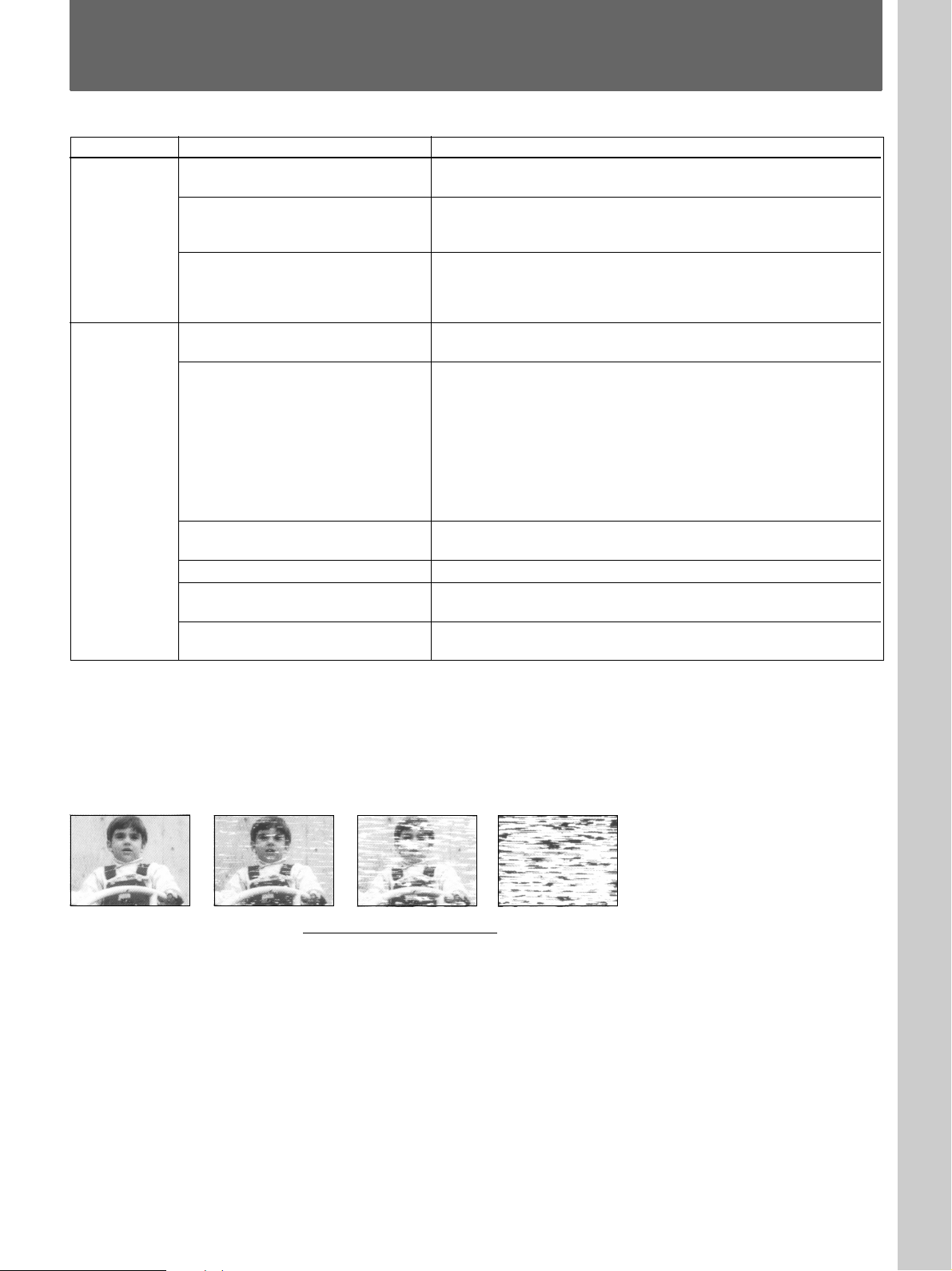
• The video heads are dirty (see below). Clean the video heads
using the Sony T-25CL video head cleaning cassette. If this
cleaning cassette is not available in your area, have the heads
cleaned at your nearest Sony service facility (a standard service
charge will be required.) Do not use a commercially available
wet-type cleaning cassette, as it may damage the video heads.
• The video heads may have to be replaced. Consult your local
Sony dealer for more information.
• Adjust the vertical hold control on the monitor.
• The tape is defective. Use a new tape.
• Check that the safety tab has not been removed.
• Make sure the tape has been wound to the beginning.
Symptoms caused by contaminated video heads
• Normal picture • Rough picture • Unclear picture
initial
• No picture
(or black & white
screen appears)
(
terminal
27 (US)
Page 28

Troubleshooting
Timer
recording
Others
Symptom
The timer does not operate.
The desired operation cannot be
selected.
A tape cannot be inserted.
A mechanical noise is heard in the
stop mode.
The VCR needs to be cleaned.
Remedy
• Check that the clock is set.
• Make sure a tape has been inserted.
• Check that the safety tab has not been removed.
• Make sure the tape has been wound to the beginning.
• Make sure a program has been set for timer recording.
•Make sure your timer settings have not already passed the
current time.
• Make sure the KEY INHIBIT ON/OFF switch is set to OFF.
• Check that a tape isn’t already in the tape compartment.
• When a tape is inserted and the VCR is left in the stop mode with
the power turned on for about 5 minutes, the tape protection
mechanism is activated automatically and a mechanical noise is
heard.
• Clean the cabinet, panel and controls with a dry, soft cloth, or a
soft cloth slightly moistened with a mild detergent solution. Do not
use any type of solvent, such as alcohol or benzine.
If you have any questions or problems concerning your unit,
please consult your nearest Sony dealer.
28 (US)
Page 29

Specifications
System
Format VHS NTSC standard
Video recording system
Rotary two-head helical scanning
FM system
Video signal NTSC color, EIA standards
Tape speed SP: 33.35 mm/s (1
EP: 11.12 mm/s (
Fast-forward and rewind time
Approx. 2 min. 30 sec (with T-120
tape)
Video resolution 240 lines (SP mode)
Video S/N 44 dB (SP mode)
Audio frequency response
50 Hz – 10 kHz
Audio S/N 40 dB
3
/8 inches/s)
7
/16 inches/s)
Inputs and outputs
Inputs VIDEO IN, BNC jack (1)
Input signal: 1 Vp-p, 75 ohms,
unbalanced, sync negative
AUDIO IN, phono jack (1)
Input level: –8 dBs (0 dBs = 0.775
Vrms)
Input impedance: more than 47
kilohms
Outputs VIDEO OUT, BNC jack (1)
Output signal: 1 Vp-p, 75 ohms,
unbalanced, sync negative
AUDIO OUT, phono jack (1)
Output level: –8 dBs
Load impedance: 47 kilohms
Output impedance: less than 10
kilohms
CONTROL S IN/OUT
Minijack (2)
REMOTE Stereo minijack (1)
WARNING OUT +5 V, 5.7 kilohms (Low active)
EJECT IN/OUT OUT: +5 V, 5.7 kilohms (Low
active)
IN: Low level
SERIES REC IN/OUT
OUT: +5 V, 5.7 kilohms (Low
active)
IN: Low level
CLOCK ADJ IN/OUT
OUT: +5 V, 5.7 kilohms (Low
active)
IN: Low level
Timer section
Clock Quartz locked
Timer indication 24-hour cycle
Timer setting Only for recording 8 programs in
one month at max (daily and
weekly)
Power back-up 30 days
General
Power requirements
120 V AC, 60 Hz
Power consumption
14 W (max.)
Operating temperature
5°C to 40°C (41°F to 104°F)
Storage temperature
–20°C to 60°C (–4°F to 140°F)
Dimensions Approx. 360 × 98 × 294 mm (w/h/
d)
(Approx. 14
inches) including projecting parts
and controls
Mass Approx. 4 kg (8 lb 13 oz)
1
/4 × 3 7/8 × 11 5/8
Supplied accessories
AC power cord (1)
Optional accessories
Remote Control Unit SVT-RM10, RM-V200
Design and specifications are subject to change
without notice.
29 (US)
Page 30

Français
AVERTISSEMENT
Afin d’éviter tout risque d’incendie ou
d’électrocution, ne pas exposer cet
appareil à la pluie ou à l’humidité.
Ce symbole est destiné à alerter l’utilisateur
sur la présence d’une “tension dangereuse”
non isolée à l’intérieur du coffret qui peut
être suffisamment forte pour constituer un
risque d’électrocution pour une personne.
Ce symbole est destiné à alerter
l’utilisateur sur la présence d’instructions
importantes sur le fonctionnement et
l’entretien (réparation) dans les instructions
accompagnant cet appareil.
Attention
Les émissions télévisées, les films, les cassettes vidéo et
autres matériaux peuvent être protégés par des droits
d’auteur. L’enregistrement non autorisé de tels matériaux
peut être en infraction avec la législation sur les droits
d’auteur. De même, l’utilisation de ce magnétoscope avec un
téléviseur relié à un réseau de télédistribution peut être
soumise à l’autorisation de l’exploitant du câble et/ou du
propriétaire du programme.
Références utilisateur
Le numéro de modèle est apposé à l’avant de l’appareil et le
numéro de série à l’arrière. Inscrivez ces numéros dans les
espaces prévus à cet effet ci-dessous. Signalez ces
numéros de référence lorsque vous prenez contact avec
votre distributeur Sony au sujet de ce produit.
o
Modèle n
No de série:
(FAROUDJA
logo)
SVO-1330
Ce lecteur intègre la technique de
filtrage Y/C sous licence de Faroudja
Laboratories Inc.
2 (FR)
Page 31

Table des matières
Présentation
Installation
Précautions ................................................................ 4 (FR)
Caractéristiques ........................................................ 5 (FR)
Emplacement et fonctions des composants et des
commandes ........................................................... 6 (FR)
Panneau frontal .............................................................. 6 (FR)
Fenêtre d’affichage ........................................................ 7 (FR)
Panneau arrière............................................................... 7 (FR)
Raccordement............................................................ 8 (FR)
Raccordement de base.................................................... 8 (FR)
Raccordement de magnétoscopes en série ..................... 8 (FR)
Sélection de la langue d’affichage........................... 9 (FR)
Réglage de l’horloge ............................................... 10 (FR)
Réglage de l’horloge .................................................... 10 (FR)
Réglage de l’heure d’été .............................................. 11 (FR)
Réglage des vibreurs .............................................. 12 (FR)
Opérations de base
Opérations complémentaires
Enregistrement ........................................................ 13 (FR)
Enregistrement ............................................................. 13 (FR)
Enregistrement de la date et de l’heure........................ 14 (FR)
Réglage de la temporisation de l’alarme de fin de cassette
................................................................................ 14 (FR)
Sélection du mode activé à la fin de la cassette ........... 14 (FR)
Contrôle des conditions d’enregistrement.................... 15 (FR)
Vérification du bobinage de la cassette........................ 15 (FR)
Contrôle de la durée d’utilisation................................. 16 (FR)
Verrouillage des touches du magnétoscope ................. 16 (FR)
Lecture d’une cassette............................................ 17 (FR)
Lecture d’une cassette.................................................. 17 (FR)
Lecture/recherche à différentes vitesses....................... 17 (FR)
Réglage de l’image .................................................. 18 (FR)
Réglage de l’alignement............................................... 18 (FR)
Utilisation du contrôle adaptatif de l’image (APC) ..... 18 (FR)
Enregistrement par programmateur ...................... 19 (FR)
Enregistrement par programmateur ............................. 19 (FR)
Vérification/modification/annulation des réglages du
programmateur........................................................ 21 (FR)
Enregistrement en série.......................................... 22 (FR)
Bornes ...................................................................... 23 (FR)
Borne WARNING OUT ............................................... 23 (FR)
Bornes EJECT IN/OUT ............................................... 23 (FR)
Bornes CLOCK ADJ IN/OUT..................................... 24 (FR)
Prise REMOTE ............................................................ 25 (FR)
Prises CONTROL S IN/OUT....................................... 26 (FR)
FR
Français
Divers
Dépannage ............................................................... 27 (FR)
Spécifications .......................................................... 29 (FR)
3 (FR)
Page 32

Précautions
Sécurité
•Faites uniquement fonctionner l’appareil sur une
tension d’alimentation de 120 V CA, 60 Hz.
•La plaquette signalétique indiquant la tension de
service, la consommation électrique, etc., est située à
l’arrière de l’appareil.
•Si quoi que ce soit venait à pénétrer dans le châssis,
débranchez l’appareil et faites-le vérifier par le
personnel qualifié avant de le remettre en service.
•Ne laissez pas tomber le cordon d’alimentation et ne
posez pas d’objets lourds dessus. Si le cordon
d’alimentation est endommagé, mettez immédiatement
l’appareil hors tension. Il est dangereux d’utiliser cet
appareil avec un cordon d’alimentation endommagé.
•Débranchez l’appareil de la prise murale si vous
prévoyez de ne pas l’utiliser pendant une période
prolongée. Pour débrancher le cordon, saisissez-le par
la fiche; ne tirez jamais sur le cordon proprement dit.
Installation
A propos des cassettes vidéo
Retirez les cassettes vidéo du magnétoscope et rangezles dans leur boîtier après lecture ou enregistrement.
Entretien
Pour des raisons de sécurité, débranchez l’appareil
avant de le nettoyer.
•Pour garder à l’appareil l’aspect du neuf, nettoyez-le
périodiquement avec une solution détergente neutre.
N’utilisez jamais de solvants puissants comme du
diluant ou de la benzine ni de produits à récurer
abrasifs, car ils risquent de ternir le fini du châssis.
Lors du nettoyage, gardez les liquides à l’écart des
contacts électriques et des connecteurs.
•Si de la poussière s’est accumulée dans les ouïes de
ventilation, éliminez-la au moyen d’un aspirateur.
Remballage
•Assurez une circulation d’air adéquate afin d’éviter
toute surchauffe interne.
•Ne placez pas l’appareil sur des surfaces textiles (tapis,
couvertures, etc.) ni à proximité de tissus (rideaux,
draperies) qui risquent d’obstruer les orifices de
ventilation.
•N’installez pas l’appareil à proximité de sources de
chaleur telles que des radiateurs et ne le soumettez pas
au rayonnement direct du soleil, à de la poussière en
excès ni à des vibrations ou à des chocs mécaniques.
•N’installez pas l’appareil dans une position inclinée. Il
a uniquement été conçu pour fonctionner dans une
position horizontale.
•Gardez l’appareil et les cassettes à l’écart de systèmes
générant de puissants champs magnétiques tels qu’un
four à micro-ondes ou des haut-parleurs de forte
puissance.
•Ne posez pas d’objets lourds sur l’appareil.
•Si l’appareil est transporté directement d’un endroit
froid dans un endroit chaud, de l’humidité risque de se
condenser à l’intérieur et d’endommager la tête vidéo
et la bande magnétique. Lorsque vous installez cet
appareil pour la première mise en service ou lorsque
vous le transportez d’un endroit froid dans un endroit
chaud, attendez environ une heure avant de le faire
fonctionner.
•Avant de remballer l’appareil, débranchez tous les
cordons et câbles de connexion.
•Conservez le carton d’emballage et les matériaux de
conditionnement, car ils constituent une protection
idéale en vue du transport de l’appareil. Lors du
transport de l’appareil, remballez-le.
Transport
Lors du transport de l’appareil, protégez-le des
vibrations et des impacts.
Si vous avez des questions à propos de cet appareil,
consultez votre revendeur Sony.
4 (FR)
Page 33

Caractéristiques
•Une fonction d’enregistrement par programmateur
qui vous permet de réaliser des enregistrements à des
heures définies, chaque jour ou chaque semaine.
•Une fonction de contrôle adaptatif de l’image (APC)
optimise automatiquement les performances
d’enregistrement et de lecture.
•Une fonction de contrôle d’enregistrement qui vous
permet de contrôler l’image enregistrée en cours
d’enregistrement.
•Commutation automatique de l’heure d’été.
•Un compteur de tête vidéo qui vous permet de
vérifier la durée d’utilisation des têtes vidéo.
•Les écrans de menu affichent les informations dans
trois langues (français, anglais ou espagnol).
•La fonction de sauvegarde de mémoire conserve,
grâce à la batterie rechargeable intégrée, les réglages
(y compris de l’horloge) pendant une durée de 30
jours en cas d’interruption de l’alimentation.
•La fonction de verrouillage des touches interdit toute
manipulation des touches du magnétoscope.
•Les prises CONTROL S IN/OUT vous permettent de
commander le défilement de la bande magnétique à
distance au départ d’un autre appareil vidéo Sony.
Si vous utilisez une télécommande filaire RM-V200
en option, vous pouvez commander jusqu’à environ
50 magnétoscopes connectés en série via CONTROL
S IN/OUT.
•L’enregistrement en série vous permet d’enregistrer
séquentiellement sur plusieurs magnétoscopes.
•Une borne de sortie de signal d’alarme qui transmet
un signal lorsqu’une défaillance se produit en cours
d’enregistrement ou que la cassette arrive en fin de
bande.
•Des bornes d’entrée/sortie d’éjection qui vous
permettent d’éjecter la cassette de plusieurs
magnétoscopes en même temps.
•Des bornes d’entrée/sortie de réglage de l’horloge qui
vous permettent de régler l’heure sur plusieurs
magnétoscopes en même temps.
Présentation
5 (FR)
Page 34

Emplacement et fonctions des composants et des commandes
Pour plus de détails, reportez-vous aux pages indiquées entre parenthèses.
Panneau fr ontal
1
2
6
1 Commutateur/indicateur POWER (13(FR))
2 Touche 6 EJECT (13
3 Compartiment à cassette (13
4 Touche TAPE SPEED (SP/EP) (13
5 Touche TIMER (19
6 Touche r REC (13
7 Touche P PAUSE (13
8 Touche ) FF (avance rapide) (17
9 Touche ( PLAY (17
!º Touche 0 REW (rembobinage) (17
(FR), 17(FR))
(FR))
(FR))
(FR))
(FR))
(FR), 17(FR))
(FR))
(FR))
(FR))
3
654
rP
p 0()
7
8!™!∞ 9!§ !º!£ !¡!¶!• !¢
!¡ Touche p STOP (13
!™ Touche RESET (27
(FR), 17(FR))
(FR))
!£ Touches TRACKING/DATA +/– (9
!¢ Fenêtre d’affichage (7
!∞ Touches SHIFT v/b (9
!§ Touche MENU (9
(FR))
(FR))
(FR))
!¶ Commutateur ON-SCREEN ON/OFF (14
!• Commutateur KEY INHIBIT ON/OFF (16
(FR), 18(FR))
(FR))
(FR))
6 (FR)
Page 35

Fenêtre d’affichage
1
X 2
TIMER
REC
AUTO TRACKING
SP EP
KEY
INHIBIT
78
9
6
5
Panneau arrière
32
H M S
4
1 Indicateur d’enregistrement TIMER
2 Indicateurs d’exploitation de cassette
3 Compteur de durée linéaire
4 Horloge
5 Indicateur REC (enregistrement)
6 Indicateur KEY INHIBIT
7 Indicateur de cassette
8 Indicateurs de vitesse de défilement de la bande
(SP/EP)
9 Indicateur AUTO TRACKING
123
4
1 Bornes CLOCK ADJ IN/OUT (24(FR))
2 Bornes SERIES REC IN/OUT (8
5
3 Borne GND (8
4 Bornes EJECT IN/OUT (23
(FR), 23(FR))
5 Borne WARNING OUT (23
6 Prises VIDEO IN/OUT (type BNC) (8
7 Prises AUDIO IN/OUT (type phono) (8
8 Prises CONTROL S IN/OUT (miniprise) (26
9 Prise REMOTE (miniprise stéréo) (25
67890
!º Connecteur AC IN (8
(FR))
(FR))
(FR))
(FR))
(FR))
(FR))
(FR))
(FR))
7 (FR)
Page 36

Raccordement
Avant de commencer...
•Mettez tous les appareils hors tension.
•Ne branchez pas le cordon d’alimentation avant que
toutes les connexions aient été établies.
•Etablissez fermement les connexions. Des
connexions lâches peuvent provoquer des distorsions
dans l’image.
Raccordement de base
Les connexions suivantes vous permettent de contrôler
l’image et le son.
Caméra vidéo, etc.
vers VIDEO OUT
vers
AUDIO
OUT
vers AUDIO IN
vers VIDEO IN
Raccordement de
magnétoscopes en série
Le raccordement suivant vous permet de réaliser des
enregistrements en série.
Caméra vidéo
Magnétoscope 1
vers
VIDEO/
AUDIO IN
vers
VIDEO/
AUDIO
OUT
vers
VIDEO/
AUDIO IN
vers
VIDEO/
AUDIO
OUT
Magnétoscope 2
Magnétoscope 3
vers SERIES
REC OUT
vers SERIES
REC IN
vers SERIES
REC OUT
vers SERIES
REC IN
vers GND
vers GND
vers GND
vers GND
vers une prise
murale
Utilisation du connecteur BNC
Alignez l’ergot sur l’encoche, enfichez et
tournez vers la droite pour verrouiller.
Pour déconnecter, tournez vers la gauche
et tirez.
vers AC IN
vers
AUDIO
OUT
Câble audio
(non fourni)
vers AUDIO IN
Moniteur
vers
VIDEO
OUT
Câble vidéo
(non fourni)
vers VIDEO IN
vers
VIDEO/
AUDIO IN
vers
VIDEO/
AUDIO
OUT
vers
VIDEO/
AUDIO IN
vers
VIDEO/
AUDIO
OUT
vers
VIDEO/
AUDIO IN
Magnétoscope 4
vers SERIES
REC OUT
vers SERIES
REC IN
vers GND
vers GND
Moniteur
Pour la procédure d’enregistrement en série, reportez-vous
à la page 22(FR).
8 (FR)
Page 37

Sélection de la langue d’affichage
1. REGL. HORL.
HEURE D’ETE
LANGUE
2. REGL. TIMER
3. PREREG
DUREE UTIL.
Installation
Sélectionnez le français, l’anglais ou l’espagnol
comme langue d’affichage des menus.
MENU
6
SHIFT b DATA +/–
SHIFT v
rP
p0()
1 Appuyez sur MENU.
Le menu principal apparaît sur l’écran du
moniteur.
1. CLOCK SET
DAYLIGHT SET
LANGUAGE
2. TIMER SET
3. SET UP
USED TIME
4 Sélectionnez la langue: ENGLISH, FRANCAIS ou
ESPANOL à l’aide des touches DATA +/– et
appuyez ensuite sur MENU.
Le menu principal apparaît dans la langue
sélectionnée.
Exemple: FRANCAIS
5 Appuyez sur MENU pour revenir à l’affichage
normal.
2 Assurez-vous que 1.CLOCK SET/DAYLIGHT
SET/LANGUAGE est sélectionné et appuyez sur
SHIFT b.
Le menu LANGUAGE apparaît.
[ CLOCK SET ]
01 - 01 - 00 00 : 00 : 00
[ DAYLIGHT SET ]
MODE NO USE
WEEK MONTH TIME
ON 1ST - SUN 04 02 : 00
OFF LST - SUN 10 02 : 00
[ LANGUAGE ]
ENGLISH
3 Appuyez sur SHIFT v pour faire clignoter la
langue.
[ CLOCK SET ]
01 - 01 - 00 00 : 00 : 00
[ DAYLIGHT SET ]
MODE NO USE
WEEK MONTH TIME
ON 1ST - SUN 04 02 : 00
OFF LST - SUN 10 02 : 00
[ LANGUAGE ]
ENGLISH
9 (FR)
Page 38

Réglage de l’horloge
Réglage de l’horloge
Réglez l’heure et la date pour pouvoir utiliser la
fonction de programmation de ce magnétoscope.
MENU
SHIFT v
6
SHIFT b DATA +/–
rP
p0()
1 Appuyez sur MENU.
Le menu principal apparaît.
1. REGL. HORL.
HEURE D’ETE
LANGUE
2. REGL. TIMER
3. PREREG
DUREE UTIL.
Réglez le jour à l’aide des touches DATA +/–.
[ REGL. HORL. ]
07 - 04 - 00 00 : 00 : 00
[ HEURE D’ETE ]
MODE ARRET
SEM. MOIS HEUR
ON 1ER - DIM 04 02 : 00
OFF DER - DIM 10 02 : 00
[ LANGUE ]
FRANCAIS
5 Appuyez sur SHIFT b pour faire clignoter l’année.
Réglez l’année à l’aide des touches DATA +/–.
[ REGL. HORL. ]
07 - 04 - 99 00 : 00 : 00
[ HEURE D’ETE ]
MODE ARRET
SEM. MOIS HEUR
ON 1ER - DIM 04 02 : 00
OFF DER - DIM 10 02 : 00
[ LANGUE ]
FRANCAIS
6 Appuyez sur SHIFT b pour faire clignoter l’heure.
Réglez l’heure à l’aide des touches DATA +/–.
[ REGL. HORL. ]
07 - 04 - 99 15 : 00 : 00
[ HEURE D’ETE ]
MODE ARRET
SEM. MOIS HEUR
ON 1ER - DIM 04 02 : 00
OFF DER - DIM 10 02 : 00
2 Assurez-vous que 1.REGL. HORL./HEURE
D’ETE/LANGUE est sélectionné et appuyez sur
SHIFT b.
Le menu REGL. HORL. apparaît à l’écran et le
mois se met à clignoter.
[ REGL. HORL. ]
01 - 01 - 00 00 : 00 : 00
[ HEURE D’ETE ]
MODE ARRET
SEM. MOIS HEUR
ON 1ER - DIM 04 02 : 00
OFF DER - DIM 10 02 : 00
[ LANGUE ]
FRANCAIS
3 Réglez le mois à l’aide des touches DATA +/–.
[ REGL. HORL. ]
07 - 01 - 00 00 : 00 : 00
[ HEURE D’ETE ]
MODE ARRET
SEM. MOIS HEUR
ON 1ER - DIM 04 02 : 00
OFF DER - DIM 10 02 : 00
[ LANGUE ]
FRANCAIS
4 Appuyez sur SHIFT b pour faire clignoter le jour.
10 (FR)
[ LANGUE ]
FRANCAIS
7 Appuyez sur SHIFT b pour faire clignoter les
minutes.
Réglez les minutes à l’aide des touches DATA +/–.
[ REGL. HORL. ]
07 - 04 - 99 15 : 00 : 00
[ HEURE D’ETE ]
MODE ARRET
SEM. MOIS HEUR
ON 1ER - DIM 04 02 : 00
OFF DER - DIM 10 02 : 00
[ LANGUE ]
FRANCAIS
8 Appuyez sur SHIFT b pour faire clignoter les
secondes.
Appuyez sur DATA – simultanément avec un signal
horaire.
L’horloge démarre à partir de 00 secondes.
9 Appuyez deux fois sur MENU pour revenir à
l’affichage normal.
Remarques
•Vous ne pouvez pas régler l’horloge pendant un
enregistrement par programmateur ni en mode de veille
d’enregistrement par programmateur.
•Pour changer ou corriger un réglage avant le démarrage
de l’horloge, appuyez sur SHIFT b pour faire clignoter
le paramètre que vous voulez changer ou corriger et
modifiez-le.
Page 39

Réglage de l’heure d’été
Changez le réglage de l’horloge au moment du passage
à l’heure d’été.
1 Affichez le menu HEURE D’ETE.
Exécutez les étapes 1 et 2 de la procédure de
“Réglage de l’horloge” à la page 10(FR).
[ REGL. HORL. ]
07 - 04 - 99 15 : 00 : 00
[ HEURE D’ETE ]
MODE ARRET
SEM. MOIS HEUR
ON 1ER - DIM 04 02 : 00
OFF DER - DIM 10 02 : 00
[ LANGUE ]
FRANCAIS
2 Appuyez sur SHIFT v pour faire clignoter le
réglage de “MODE”.
[ REGL. HORL. ]
07 - 04 - 99 15 : 00 : 00
[ HEURE D’ETE ]
MODE ARRET
SEM. MOIS HEUR
ON 1ER - DIM 04 02 : 00
OFF DER - DIM 10 02 : 00
[ LANGUE ]
FRANCAIS
3 Sélectionnez MARCHE à l’aide des touches
DATA +/– pour procéder au réglage de l’heure
d’été.
[ REGL. HORL. ]
07 - 04 - 99 15 : 00 : 00
[ HEURE D’ETE ]
MODE MARCHE
SEM. MOIS HEUR
ON 1ER - DIM 04 02 : 00
OFF DER - DIM 10 02 : 00
[ LANGUE ]
FRANCAIS
4 Appuyez sur SHIFT v et changez la date et l’heure
au moment de régler l’heure d’été.
[ REGL. HORL. ]
07 - 04 - 99 15 : 00 : 00
[ HEURE D’ETE ]
MODE MARCHE
SEM. MOIS HEUR
ON 1ER - DIM 04 02 : 00
OFF DER - DIM 10 02 : 00
[ LANGUE ]
FRANCAIS
Date et heure d’activation
(ON) de l’heure d’été
Date et heure de
désactivation (OFF) de
l’heure d’été
SEM. ON
Réglez la semaine de passage à l’heure d’été à
l’aide des touches DATA +/–: Sélectionnez
1ER, 2EM, 3EM, 4EM ou DER pour la
première, la deuxième, la troisième, la
quatrième ou la dernière semaine.
Appuyez ensuite sur SHIFT b et réglez le jour
de la semaine à l’aide des touches DATA +/–:
DIM, LUN, ..., SAM.
MOIS ON
Appuyez sur SHIFT b et réglez le mois à l’aide
des touches DATA +/–: 01, 02, ..., 12 pour
janvier, février, ..., décembre.
HEUR ON
Appuyez sur SHIFT b et réglez l’heure à l’aide
des touches DATA +/–. L’heure ne peut être
réglée qu’entre 01 et 22.
Appuyez ensuite sur SHIFT b et réglez les
minutes à l’aide des touches DATA +/–.
Remarque
Pour corriger des réglages, appuyez sur SHIFT v
et/ou SHIFT b pour faire clignoter le réglage que
vous voulez changer et changez le réglage.
5 Appuyez sur SHIFT v et réglez la date et l’heure
pour revenir à l’heure normale de la même
manière.
6 Appuyez deux fois sur MENU pour revenir à
l’affichage normal.
11 (FR)
Page 40

Réglage des vibreurs
Vous pouvez activer/désactiver les vibreurs suivants.
•Vibreur FIN CASSETTE: Retentit lorsque la
cassette arrive en fin de bande ou que le compteur de
bande affiche la valeur définie sous l’option “FIN
CASSETTE” dans le menu PREREG.
•Vibreur d’avertissement: Retentit lorsque l’appareil
transmet un signal d’avertissement via la borne
WARNING OUT.
6
MENU
SHIFT b
SHIFT v
rP
p0()
DATA +/–
1 Appuyez sur MENU.
Le menu principal apparaît.
1. REGL. HORL.
HEURE D’ETE
LANGUE
4 Réglez-le sur ON ou OFF à l’aide des touches
DATA +/–.
[ PREREG ]
CASSETTE
FIN ALARME
FIN CASSETTE
APC
REGLAGE HORLOGE
AVERTIS.
VERI. ENREG.
[ DUREE UTIL. ]
TETE 00005H
T-120
FIN
REMB
ON
0 1 : 0 0
OFF
ON
5 Appuyez deux fois sur MENU pour revenir à
l’affichage normal.
Pour arrêter le vibreur FIN CASSETTE
Appuyez sur la touche p STOP.
Pour arrêter le vibreur d’avertissement
Appuyez sur l’une des touches de commande de la
bande (par ex., p STOP).
2. REGL. TIMER
3. PREREG
DUREE UTIL.
2 Appuyez sur SHIFT v pour sélectionner
3.PREREG/DUREE UTIL. et appuyez ensuite sur
SHIFT b.
Le menu PREREG apparaît à l’écran.
[ PREREG ]
CASSETTE
FIN ALARME
FIN CASSETTE
APC
REGLAGE HORLOGE
AVERTIS.
VERI. ENREG.
[ DUREE UTIL. ]
TETE 00005H
T-120
FIN
REMB
ON
0 1 : 0 0
ON
ON
3 Appuyez sur SHIFT v pour faire clignoter le
réglage de “AVERTIS.”.
[ PREREG ]
CASSETTE
FIN ALARME
FIN CASSETTE
APC
REGLAGE HORLOGE
AVERTIS.
VERI. ENREG.
[ DUREE UTIL. ]
TETE 00005H
T-120
FIN
REMB
ON
0 1 : 0 0
ON
ON
12 (FR)
Page 41

Enregistrement
Opérations de base
Enregistrement
Cette section vous explique comment enregistrer le
signal transmis par les sources d’entrée raccordées au
magnétoscope.
6
6 EJECT
1234
rP
p0()
p STOP
P PAUSE
1 Mettez sous tension l’appareil que vous comptez
utiliser.
2 Introduisez une cassette dont l’onglet de sécurité est
intact.
L’indicateur de cassette clignote pendant environ 5
secondes et le magnétoscope vérifie le bobinage de
la cassette. Durant cette période, les touches (
PLAY, r REC, ) FF et 0 REW sont
inopérantes.
Pour plus de détails, voir “Vérification du bobinage de la
cassette” à la page 15(FR).
3 Réglez la vitesse de défilement de la bande, SP
(durée standard) ou EP (longue durée), en appuyant
sur TAPE SPEED.
Voir “Pour sélectionner la vitesse de défilement de la
bande”.
4 Démarrez l’enregistrement en appuyant sur r REC.
L’indicateur REC du magnétoscope s’allume.
Remarques
• Si vous introduisez une cassette dont l’onglet de sécurité a
été brisé, elle est éjectée lorsque vous appuyez sur r REC.
Pour pouvoir enregistrer sur cette cassette, recouvrez
l’orifice de bande adhésive.
• Chaque fois que vous introduisez une cassette et que vous
démarrez l’enregistrement, la fonction de contrôle adaptatif
de l’image (APC) optimise automatiquement la qualité
d’enregistrement en adaptant le magnétoscope à l’état de la
bande magnétique et des têtes vidéo. Il faut compter un
décalage d’environ 6 secondes avant que le magnétoscope
démarre l’enregistrement proprement dit après que vous avez
appuyé sur la touche r REC.
Pour plus de détails, voir “Utilisation du contrôle adaptatif
de l’image (APC)” à la page 18(FR).
• Si une panne de courant se produit en cours
d’enregistrement, le magnétoscope reprendra
l’enregistrement dès que l’alimentation aura été rétablie.
Pour arrêter l’enregistrement
Appuyez sur p STOP.
Pour couper une scène indésirable en cours
d’enregistrement
Appuyez sur P PAUSE. Appuyez ensuite à nouveau
sur cette touche pour reprendre l’enregistrement.
Remarque
Si le mode de pause d’enregistrement est activé pendant
plus d’environ 5 minutes, le magnétoscope passe
automatiquement en mode d’arrêt.
Pour éjecter une cassette
Appuyez sur 6 EJECT.
Vous pouvez éjecter la cassette même lorsque le
magnétoscope est hors tension. Lorsque vous appuyez
sur 6 EJECT, le magnétoscope se met
automatiquement sous tension et puis à nouveau hors
tension après avoir éjecté la cassette.
Pour sélectionner la vitesse de défilement de la
bande
Pour l’enregistrement, sélectionnez SP (durée standard)
ou EP (longue durée) en appuyant sur TAPE SPEED.
Le mode EP assure une durée d’enregistrement triple de
celle du mode SP. Mais le mode SP fournit cependant
une meilleure qualité d’image. Vous pouvez employer
les modes SP et EP sur la même cassette. Lorsque vous
reproduisez une cassette, le magnétoscope détecte
automatiquement la vitesse de défilement de la bande.
Consultez le tableau ci-dessous pour la durée de lecture/
enregistrement maximum dans chaque vitesse.
Type de cassette Durée de lecture/enregistrement maximum
SP EP
T-160 2 h 40 min. 8 heures
T-120 2 heures 6 heures
Sauvegarde d’un enregistrement
Les cassettes vidéo sont dotées d’un onglet de sécurité
destiné à prévenir tout enregistrement accidentel. Pour
empêcher l’effacement accidentel d’un enregistrement,
brisez l’onglet de sécurité à l’aide d’un tournevis ou
d’un ustensile similaire. Une cassette dont l’onglet de
sécurité a été brisé est éjectée du magnétoscope si vous
essayez d’enregistrer dessus.
Pour pouvoir enregistrer sur cette cassette, recouvrez
simplement de bande adhésive l’orifice de l’onglet.
Onglet de
sécurité
Bande adhésive
13 (FR)
Page 42

Enregistrement
[ PREREG ]
[ DUREE UTIL. ]
TETE 00005H
FIN ALARME
FIN CASSETTE
REGLAGE HORLOGE
AVERTIS.
VERI. ENREG.
CASSETTE
APC
T-160
0 2 : 4 0
REMB
ON
0 1 : 0 0
ON
ON
Enregistrement de la date et de
l’heure
Vous pouvez enregistrer la date et l’heure
d’enregistrement sur la cassette en même temps que
l’image.
6
ON SCREEN ON/OFF
Réglez le commutateur ON SCREEN ON/OFF sur
ON. La date et l’heure apparaissent à l’écran. Si vous
démarrez l’enregistrement dans cette condition, la date
et l’heure affichées sont enregistrées sur la cassette en
même temps que l’image.
Pour désactiver la date et l’heure, réglez le
commutateur ON SCREEN ON/OFF sur OFF.
rP
p0()
FIN: Un signal d’alarme est transmis lorsque la
cassette arrive en fin de bande.
02:00, etc.: Un signal d’alarme est transmis
lorsque le compteur de bande affiche la durée
sélectionnée (soit la longueur de bande nominale
en heures et en minutes).
La durée qui apparaît dépend du réglage de
“CASSETTE” et de la vitesse d’enregistrement
(SP ou EP). Réglez correctement la longueur de
bande sous “CASSETTE” (T-120 ou T-160).
Si “CASSETTE” est réglé sur T-120, 02:00
apparaît en mode SP et 06:00 en mode EP;
Si “CASSETTE” est réglé sur T-160, 02:40
apparaît en mode SP et 08:00 en mode EP.
4 Appuyez sur SHIFT v pour faire clignoter le
réglage de “CASSETTE” et sélectionnez T-120 ou
T-160 à l’aide des touches DATA +/–.
(Vous pouvez sauter cette étape si vous réglez
“FIN ALARME” sur FIN à l’étape 3.)
Réglage de la temporisation de l’alarme de fin de cassette
Vous pouvez sélectionner le délai au bout duquel le
vibreur TAPE est activé pour signaler que la cassette
arrive en fin de bande ou la longueur de bande
nominale (avant la fin).
1 Appuyez sur MENU et sélectionnez 3.PREREG/
DUREE UTIL. à l’aide de la touche SHIFT v et
appuyez ensuite sur SHIFT b.
Le menu PREREG apparaît à l’écran.
2 Appuyez sur SHIFT v pour faire clignoter le
réglage de “FIN ALARME”.
3 Réglez “FIN ALARME” sur FIN ou 02:00, par
exemple (longueur de bande nominale), à l’aide
des touches DATA +/–.
[ PREREG ]
CASSETTE
FIN ALARME
FIN CASSETTE
APC
REGLAGE HORLOGE
AVERTIS.
VERI. ENREG.
[ DUREE UTIL. ]
TETE 00005H
14 (FR)
T-120
FIN
REMB
ON
0 1 : 0 0
ON
ON
5 Appuyez deux fois sur MENU pour revenir à
l’affichage normal.
Sélection du mode activé à la fin de la cassette
Vous pouvez rembobiner ou éjecter la cassette
lorsqu’elle est arrivée en fin de bande durant un
enregistrement.
1 Appuyez sur MENU et sélectionnez 3.PREREG/
DUREE UTIL. à l’aide de la touche SHIFT v et
appuyez ensuite sur SHIFT b.
Le menu PREREG apparaît à l’écran.
2 Appuyez sur SHIFT v pour faire clignoter le
réglage de “FIN ALARME”.
Page 43

3 Réglez “FIN CASSETTE” sur REMB ou EJECT à
[ PREREG ]
[ DUREE UTIL. ]
TETE 00005H
FIN ALARME
FIN CASSETTE
REGLAGE HORLOGE
AVERTIS.
VERI. ENREG.
CASSETTE
APC
T-120
FIN
REMB
ON
0 1 : 0 0
OFF
ON
[ PREREG ]
[ DUREE UTIL. ]
TETE 00005H
FIN ALARME
FIN CASSETTE
REGLAGE HORLOGE
AVERTIS.
VERI. ENREG.
CASSETTE
APC
T-120
FIN
REMB
ON
0 1 : 0 0
OFF
OFF
l’aide des touches DATA +/–.
[ PREREG ]
CASSETTE
FIN ALARME
FIN CASSETTE
APC
REGLAGE HORLOGE
AVERTIS.
VERI. ENREG.
[ DUREE UTIL. ]
TETE 00005H
REMB: lorsque la cassette arrive en fin de bande,
le magnétoscope la rembobine automatiquement
et passe en mode d’arrêt au début de la cassette.
EJECT: lorsque la cassette arrive en fin de bande,
elle est automatiquement éjectée.
T-120
FIN
REMB
ON
0 1 : 0 0
ON
ON
Vérification du bobinage de la cassette
Pour garantir un bon fonctionnement, le magnétoscope
contrôle automatiquement le bobinage de la cassette
chaque fois que vous en introduisez une, ce qui prend
environ 5 secondes. Si le magnétoscope détecte une
erreur, la cassette est éjectée.
Durant cette période, les touches de commande de
cassette ( PLAY, r REC, ) FF et 0 REW sont
inopérantes.
Si vous jugez inutile de procéder à la vérification du
bobinage de la cassette, vous pouvez la désactiver dans
le menu PREREG.
4 Appuyez deux fois sur MENU pour revenir à
l’affichage normal.
Contrôle des conditions d’enregistrement
Vous pouvez contrôler les conditions d’enregistrement
en appuyant sur ( PLAY pendant l’enregistrement.
6
Appuyez sur ( PLAY en cours d’enregistrement.
Après que la cassette a été rembobinée pendant
environ trois secondes et reproduite pendant environ
deux secondes, l’appareil revient dans le mode
d’enregistrement original.
rP
p0()
(PLAY
1 Appuyez sur MENU et sélectionnez 3.PREREG/
DUREE UTIL. à l’aide de SHIFT v et appuyez
ensuite sur SHIFT b.
Le menu PREREG apparaît à l’écran.
2 Appuyez sur SHIFT v pour faire clignoter le
réglage de “VERI. ENREG.”.
3 Sélectionnez OFF pour désactiver le contrôle du
bobinage de la cassette à l’aide des touches DATA
+/–.
Remarques
•L’enregistrement est interrompu pendant le contrôle
des conditions d’enregistrement.
•Si l’enregistrement n’est pas correctement effectué,
un signal d’alarme est transmis via la borne
WARNING OUT.
4 Appuyez deux fois sur MENU pour revenir à
l’affichage normal.
15 (FR)
Page 44

Enregistrement
Contrôle de la durée d’utilisation
Vous pouvez vérifier la durée d’utilisation des têtes
vidéo via le menu DUREE UTIL.
1 Appuyez sur SHIFT v pour sélectionner
3.PREREG/DUREE UTIL. et appuyez ensuite sur
SHIFT b.
Le menu PREREG apparaît à l’écran.
2 Contrôlez le compteur de tête vidéo.
[ PREREG ]
CASSETTE
FIN ALARME
FIN CASSETTE
APC
REGLAGE HORLOGE
AVERTIS.
VERI. ENREG.
[ DUREE UTIL. ]
TETE 00005H
T-120
FIN
REMB
ON
0 1 : 0 0
ON
ON
Compteur de tête vidéo
3 Appuyez deux fois sur MENU pour revenir à
l’affichage normal.
Verrouillage des touches du magnétoscope
Vous pouvez verrouiller les touches du magnétoscope.
Cette fonction s’avère bien pratique pour éviter toute
manipulation accidentelle pendant que vous
commandez ce magnétoscope à l’aide d’une
télécommande filaire (non fournie). Elle est également
bien pratique lorsque vous utilisez le magnétoscope
dans un lieu public, car elle empêche tout
dysfonctionnement à la suite de manipulations par
d’autres personnes.
6
KEY INHIBIT ON/OFF
rP
p0()
Réglez le commutateur KEY INHIBIT ON/OFF du
magnétoscope sur ON.
L’indication “KEY INHIBIT” apparaît dans la fenêtre
d’affichage du magnétoscope et les touches du
magnétoscope sont verrouillées.
Pour reprendre le mode de fonctionnement normal,
réglez le commutateur KEY INHIBIT ON/OFF sur
OFF.
16 (FR)
Page 45

Lecture d’une cassette
Lecture d’une cassette
Cette section vous explique comment reproduire une
cassette vidéo.
23
6 EJECT
6
p STOP
0 REW ) FF
rP
p0()
P PAUSE
1 Mettez sous tension l’appareil que vous comptez
utiliser.
2 Introduisez une cassette.
Le magnétoscope se met automatiquement sous
tension.
L’indicateur de cassette clignote pendant environ 5
secondes et le magnétoscope vérifie le bobinage de
la cassette.
Durant cette période, les touches ( PLAY, r
REC, ) FF et 0 REW sont inopérantes.
Pour plus de détails, voir “Vérification du bobinage de
la cassette” à la page 15(FR).
3 Appuyez sur ( PLAY pour démarrer la lecture.
Fonctions complémentaires
Lecture/recherche à différentes vitesses
Vous pouvez reproduire une cassette à différentes
vitesses: grande vitesse, arrêt sur image, ralenti, etc.
Ces options s’avèrent bien pratiques pour rechercher
un passage spécifique en cours de lecture. Le son est
coupé durant ces opérations.
Recherche d’image
En cours de lecture, maintenez la touche ) FF
(recherche avant) ou 0 REW (recherche arrière)
enfoncée. Une image défilant à grande vitesse apparaît
sur l’écran du moniteur. Pour reprendre la lecture
normale, relâchez la touche ) FF ou 0 REW.
Remarque
En cours de recherche d’image, des rayures ou des
parasites apparaissent sur l’écran du moniteur.
Arrêt sur image
En cours de lecture, appuyez sur P PAUSE.
Pour reprendre la lecture normale, appuyez sur (
PLAY.
Si le mode d’arrêt sur image est maintenu pendant plus
d’environ cinq minutes, le magnétoscope reprend
automatiquement le mode de lecture normale.
Si l’image oscille en mode d’arrêt sur image
Ajustez l’image à l’aide des touches TRACKING/
DATA +/–.
Pour Appuyez sur
Arrêter la lecture p STOP
Avancer rapidement la cassette ) FF en mode d’arret
Rembobiner la cassette 0 REW en mode
d’arret
Ejecter la cassette 6 EJECT
Pour des informations plus détaillées sur les fonctions de
recherche et de lecture, reportez-vous à la section “Lecture/
recherche à différentes vitesses”.
Image au ralenti
En mode d’arrêt, appuyez sur P PAUSE à nouveau
pour obtenir une image au ralenti à un cinquième de la
vitesse de lecture normale. En appuyant à nouveau sur
la touche P PAUSE, le mode d’arrêt sur image est
restauré.
Pour reprendre la lecture normale, appuyez sur (
PLAY.
17 (FR)
Page 46

Réglage de l’image
Réglage de l’alignement
Bien que le magnétoscope ajuste automatiquement
l’alignement pendant la lecture d’une cassette
(l’indicateur AUTO TRACKING clignote dans la
fenêtre d’affichage, puis s’allume en continu), des
distorsions peuvent se produire si la cassette a été
enregistrée dans de mauvaises conditions. Si c’est le
cas, procédez au réglage manuel de l’alignement.
6
Indicateur AUTO
TRACKING
TRACKING/DATA +/–
rP
p0()
Appuyez sur TRACKING/DATA +/–. (L’indicateur
AUTO TRACKING s’éteint.) Les distorsions doivent
disparaître lorsque vous appuyez sur l’une des deux
touches.
Pour revenir au mode de réglage automatique, appuyez
simultanément sur TRACKING/DATA + et –.
Utilisation du contrôle adaptatif de l’image (APC)
La fonction de contrôle adaptatif de l’image (APC)
améliore automatiquement la qualité de lecture et
d’enregistrement en ajustant le magnétoscope à l’état
des têtes vidéo et de la bande magnétique. Pour
maintenir la meilleure qualité d’image possible, il est
conseillé de régler “APC” sur ON dans le menu
PREREG.
1 Appuyez sur MENU et sélectionnez 3.PREREG/
DUREE UTIL. à l’aide de la touche SHIFT v et
appuyez ensuite sur SHIFT b.
Le menu PREREG apparaît.
[ PREREG ]
CASSETTE
FIN ALARME
FIN CASSETTE
APC
REGLAGE HORLOGE
AVERTIS.
VERI. ENREG.
[ DUREE UTIL. ]
TETE 00005H
T-120
FIN
REMB
ON
0 1 : 0 0
ON
ON
2 Appuyez sur SHIFT v pour faire clignoter le
réglage de “APC”.
[ PREREG ]
CASSETTE
FIN ALARME
FIN CASSETTE
APC
REGLAGE HORLOGE
AVERTIS.
VERI. ENREG.
[ DUREE UTIL. ]
TETE 00005H
T-120
FIN
REMB
ON
0 1 : 0 0
ON
ON
3 Réglez-le sur ON pour exploiter la fonction APC
avec les touches DATA +/–.
4 Appuyez deux fois sur MENU pour revenir à
l’affichage normal.
Pour activer la fonction APC en cours de
lecture
La fonction APC est activée automatiquement avec
tous les types de cassettes. Vous pouvez reproduire
une cassette avec la fonction APC même si la cassette
n’a pas été enregistrée avec cette fonction.
Utilisation de la fonction APC en cours
d’enregistrement
Chaque fois que vous introduisez une cassette et que
vous démarrez l’enregistrement pour la première fois,
le magnétoscope s’adapte à la cassette à l’aide de la
fonction APC.
Ce réglage est maintenu jusqu’à ce que la cassette ait
été éjectée. Il y a un bref décalage avant que le
magnétoscope démarre l’enregistrement proprement
dit pendant lequel il analyse la cassette.
Remarque
Si la fonction APC n’est pas correctement opérante en
raison d’un encrassement de la tête vidéo ou de toute
autre raison, un signal d’alarme est transmis via la
borne WARNING OUT. En cours d’enregistrement,
l’indicateur REC clignote dans la fenêtre d’affichage,
mais l’enregistrement continue même dans cette
condition.
18 (FR)
Page 47

Enregistrement par programmateur
Enregistrement par programmateur
Cette section décrit comment programmer le
magnétoscope pour démarrer et arrêter
automatiquement l’enregistrement d’une émission
télévisée. Vous pouvez programmer jusqu’à 8
émissions en vue de leur enregistrement par
programmateur dans un délai d’un mois.
Avant de commencer...
•Vérifiez si l’horloge est correctement réglée.
•Pour un enregistrement par programmateur,
introduisez une cassette dont l’onglet de sécurité est
intact. Assurez-vous que la longueur de bande
disponible est supérieure à la durée totale des
enregistrements que vous avez programmés.
•Mettez sous tension l’appareil que vous comptez
utiliser.
6
MENU DATA +/–
SHIFT v TIMER
SHIFT b
rP
p0()
1 Appuyez sur MENU et sélectionnez 2.REGL.
TIMER avec la touche SHIFT v et appuyez ensuite
sur SHIFT b.
Le menu REGL. TIMER apparaît et la date du jour
se met à clignoter.
Remarque
Vous pouvez programmer la date dans un délai
d’un mois seulement, sauf pour l’enregistrement
quotidien/hebdomadaire, qui reste opérant jusqu’à
ce que vous le modifiiez.
Pour enregistrer la même émission tous les jours ou
chaque semaine, reportez-vous à la section
“Enregistrement quotidien/hebdomadaire” à la page
20(FR).
3 Appuyez sur SHIFT b et réglez l’heure de début
d’enregistrement à l’aide des touches DATA +/–:
Appuyez sur SHIFT b pour faire clignoter l’heure
sous “DEBUT” et réglez ensuite l’heure à l’aide
des touches DATA +/–.
[ REGL. TIMER ]
DATE DEBUT ARRET MODE
1 0 1 3:– – – –:– – EP
– – – –:– – – –:– – – –
– – – –:– – – –:– – – –
– – – –:– – – –:– – – –
– – – –:– – – –:– – – –
– – – –:– – – –:– – – –
– – – –:– – – –:– – – –
– – – –:– – – –:– – – –
Appuyez sur SHIFT b pour faire clignoter les
minutes sous “DEBUT” et réglez ensuite les
minutes à l’aide des touches DATA +/–.
[ REGL. TIMER ]
DATE DEBUT ARRET MODE
1 0 1 3:1 5 – –:– – EP
– – – –:– – – –:– – – –
– – – –:– – – –:– – – –
– – – –:– – – –:– – – –
– – – –:– – – –:– – – –
– – – –:– – – –:– – – –
– – – –:– – – –:– – – –
– – – –:– – – –:– – – –
[ REGL. TIMER ]
DATE DEBUT ARRET MODE
0 4 – –:– – – –:– – EP
– – – –:– – – –:– – – –
– – – –:– – – –:– – – –
– – – –:– – – –:– – – –
– – – –:– – – –:– – – –
– – – –:– – – –:– – – –
– – – –:– – – –:– – – –
– – – –:– – – –:– – – –
2 Réglez la “DATE” de début d’enregistrement à
l’aide des touches DATA +/–.
[ REGL. TIMER ]
DATE DEBUT ARRET MODE
1 0 – –:– – – –:– – EP
– – – –:– – – –:– – – –
– – – –:– – – –:– – – –
– – – –:– – – –:– – – –
– – – –:– – – –:– – – –
– – – –:– – – –:– – – –
– – – –:– – – –:– – – –
– – – –:– – – –:– – – –
4 Appuyez sur SHIFT b et réglez l’heure d’arrêt
d’enregistrement suivant la même procédure à
l’aide des touches DATA +/–.
[ REGL. TIMER ]
DATE DEBUT ARRET MODE
1 0 1 3:1 5 1 4:0 0 EP
– – – –:– – – –:– – – –
– – – –:– – – –:– – – –
– – – –:– – – –:– – – –
– – – –:– – – –:– – – –
– – – –:– – – –:– – – –
– – – –:– – – –:– – – –
– – – –:– – – –:– – – –
(suite page suivante)
19 (FR)
Page 48

Enregistrement par programmateur
5 Appuyez sur SHIFT b et sélectionnez la vitesse de
défilement de la bande (SP ou EP) à l’aide des
touches DATA +/–
Pour plus de détails sur le réglage de la vitesse de
défilement de la bande, voir page 13(FR).
[ REGL. TIMER ]
DATE DEBUT ARRET MODE
1 0 1 3:1 5 1 4:0 0 SP
– – – –:– – – –:– – – –
– – – –:– – – –:– – – –
– – – –:– – – –:– – – –
– – – –:– – – –:– – – –
– – – –:– – – –:– – – –
– – – –:– – – –:– – – –
– – – –:– – – –:– – – –
Pour programmer un autre réglage, appuyez sur
SHIFT v pour faire clignoter la date sur la ligne
suivante et répétez les étapes 2 à 5.
Pour corriger des réglages, appuyez sur SHIFT v
et SHIFT b pour faire clignoter le réglage que
vous voulez changer et modifiez-le.
6 Après avoir terminé les réglages, appuyez deux
fois sur MENU et puis sur TIMER.
L’indicateur TIMER s’allume dans la fenêtre
d’affichage, le magnétoscope se met hors tension
et passe en mode de veille d’enregistrement.
Le magnétoscope se met ensuite automatiquement
sous tension et démarre l’enregistrement 15
secondes avant l’heure programmée.
Remarques
•L’indicateur TIMER clignote si vous
programmez l’heure d’activation dans les 5
minutes.
•Si vous introduisez une cassette dont l’onglet de
sécurité a été brisé, le magnétoscope l’éjecte à
l’heure de début de l’enregistrement programmé.
Pour arrêter un enregistrement par
programmateur
Pour arrêter la cassette pendant un enregistrement par
programmateur, appuyez sur TIMER de façon à
désactiver l’indicateur TIMER dans la fenêtre
d’affichage.
En cas de panne de courant
• Si une panne de courant se produit durant un
enregistrement par programmateur et si l’heure
d’arrêt programmée n’est pas dépassée lorsque
l’alimentation est rétablie, le magnétoscope reprend
l’enregistrement par programmateur.
• Même si une panne de courant se produit en cours de
pause d’enregistrement par programmateur, le
réglage reste effectif jusqu’à ce que l’heure d’arrêt
programmée soit passée. Si l’alimentation est rétablie
pendant la période d’enregistrement programmée, le
magnétoscope démarre immédiatement
l’enregistrement.
Enregistrement quotidien/hebdomadaire
Vous pouvez programmer le magnétoscope pour
enregistrer la même émission chaque jour de la
semaine (enregistrement quotidien) ou le même jour de
chaque semaine (enregistrement hebdomadaire).
Appuyez sur DATA – à l’étape 2 de la page 19(FR)
jusqu’à ce que le réglage voulu apparaisse à la position
DATE.
Chaque fois que vous appuyez sur DATA –, le réglage
change selon la séquence suivante:
4 (aujourd’hui) n SAM (tous les samedis) n VEN
n JEU n MER n MAR n LUN n DIM n LUVE (du lundi au vendredi) n LU-SA (du lundi au
samedi) n LU-DI (tous les jours)
Utilisation du magnétoscope avant un
enregistrement par programmateur
Appuyez sur TIMER pour désactiver l’indicateur
TIMER dans la fenêtre d’affichage et appuyez ensuite
sur POWER.
Le magnétoscope est prêt à l’emploi.
Lorsque vous avez terminé d’employer le
magnétoscope, appuyez à nouveau sur TIMER pour
réactiver l’indicateur TIMER dans la fenêtre
d’affichage.
A propos du bip sonore
Un bip sonore d’avertissement retentit dans les cas
suivants:
•Si vous appuyez sur TIMER lorsque
– aucune émission n’a été programmée en vue d’un
enregistrement par programmateur;
– aucune cassette n’a été introduite.
•Si vous essayez de changer d’émission programmée
pendant un enregistrement par programmateur.
•Si vous essayez de régler l’horloge pendant un
enregistrement par programmateur.
•Si vous essayez de régler un enregistrement par
programmateur alors que l’horloge n’a pas été réglée.
20 (FR)
Page 49

Vérification/modification/
10:00
10:50
11:30
annulation des réglages du programmateur
Cette section vous explique comment vérifier, modifier
et annuler les réglages du programmateur que vous
avez mémorisés dans le magnétoscope.
Avant de commencer...
Mettez votre moniteur sous tension.
6 Appuyez deux fois sur MENU.
Le magnétoscope revient à l’écran de départ. S’il
reste d’autres réglages de programmation dans le
menu REGL. TIMER, appuyez sur TIMER pour
revenir en mode de veille d’enregistrement.
Pour vérifier les réglages du programmateur
pendant un enregistrement par programmateur
Appuyez sur MENU et sélectionnez 2.REGL. TIMER.
Après vérification, appuyez deux fois sur MENU pour
désactiver l’affichage.
1 Appuyez sur TIMER pour désactiver l’indicateur
TIMER dans la fenêtre d’affichage.
2 Appuyez sur POWER pour mettre le magnétoscope
sous tension.
3 Appuyez sur MENU et
sélectionnez 2.REGL.
TIMER à l’aide de la
touche v et appuyez
ensuite sur SHIFT b.
Le menu REGL.
TIMER apparaît.
[ REGL. TIMER ]
DATE DEBUT ARRET MODE
1 0 1 3:1 5 1 4:0 0 SP
LUN 0 2:0 0 0 3:0 0 SP
0 4 1 1:0 0 1 1:5 0 SP
LU-SA
0 9:0 0 1 0:3 0 EP
– – – –:– – – –:– – – –
– – – –:– – – –:– – – –
– – – –:– – – –:– – – –
– – – –:– – – –:– – – –
4 Vérification des réglages du programmateur:
Si vous ne devez pas modifier ni annuler les
réglages, appuyez sur MENU et puis sur TIMER
pour revenir en mode de veille d’enregistrement.
5 Modification ou annulation des réglages du
programmateur:
• Pour modifier un
réglage, appuyez sur
SHIFT v et SHIFT b
pour faire clignoter le
paramètre que vous
voulez changer et
changez-le avec les
touches DATA +/–.
• Pour annuler un réglage, appuyez sur SHIFT v et
SHIFT b pour faire clignoter le réglage “MODE”
de l’emission que vous
voulez annuler, et
réglez-le ensuite sur
“– –” à l’aide des
touches DATA +/–.
En appuyant sur
SHIFT v, la
programmation est
annulée.
[ REGL. TIMER ]
DATE DEBUT ARRET MODE
1 0 1 3:1 5 1 4:0 0 SP
LUN 0 2:0 0 0 4:0 0 SP
0 4 1 1:0 0 1 1:5 0 SP
LU-SA
0 9:0 0 1 0:3 0 EP
– – – –:– – – –:– – – –
– – – –:– – – –:– – – –
– – – –:– – – –:– – – –
– – – –:– – – –:– – – –
[ REGL. TIMER ]
DATE DEBUT ARRET MODE
1 0 1 3:1 5 1 4:0 0 SP
LUN 0 2:0 0 0 3:0 0 SP
– – – –:– – – –:– – – –
LU-SA
0 9:0 0 1 0:3 0 EP
– – – –:– – – –:– – – –
– – – –:– – – –:– – – –
– – – –:– – – –:– – – –
– – – –:– – – –:– – – –
Si des réglages du programmateur se
chevauchent
Le magnétoscope n’enregistre pas les émissions qui se
chevauchent. Si des programmations se chevauchent,
changez les réglages.
Cas 1: Si vous avez programmé le début
d’enregistrement de deux émissions pour la même
heure...
La première émission programmée dans le menu
TIMER SET a la priorité sur les autres émissions. La
programmation des émissions d’un rang de priorité
inférieur démarre lorsque le magnétoscope a terminé
l’enregistrement de la première émission.
Cas 1
Emission 1
(programmée d’abord)
Emission 2
(programmée ensuite)
Sera coupé.
Cas 2: Si vous avez programmé le début
d’enregistrement de l’émission 1 avant la fin de
l’enregistrement de l’émission 2...
L’enregistrement de l’émission 1 démarre après la fin de
l’enregistrement de l’émission 2.
Cas 2
Emission 1
Emission 2
Remarque
10:00
10:30
11:30
Sera
coupé.
11:00
Le magnétoscope démarre l’enregistrement 15 secondes
avant l’heure d’activation programmée.
A propos de la fonction de sauvegarde de
mémoire
Le magnétoscope est doté d’une fonction de sauvegarde
de la mémoire. Même si l’alimentation est interrompue,
les réglages mémorisés sont conservés jusqu’à 30 jours
grâce à la pile rechargeable intégrée.
21 (FR)
Page 50

Enregistrement en série
Si vous connectez plusieurs magnétoscopes SVO-1330
en série, vous pouvez démarrer automatiquement
l’enregistrement sur un magnétoscope lorsque la
cassette d’un autre magnétoscope est arrivée en fin de
bande.
Pour le raccordement, voir “Raccordement de
magnétoscopes en série” à la page 8(FR).
Avant de commencer...
•Introduisez dans chaque magnétoscope une cassette
dont l’onglet de sécurité est intact.
•Assurez-vous que l’indicateur TIMER est désactivé
sur tous les magnétoscopes.
•Réglez correctement la vitesse d’enregistrement, SP
(durée standard) ou EP (longue durée) sur chaque
magnétoscope.
Magnétoscope 1
6
2
Magnétoscope 2
6
POWER OFF
rP
p0()
3
rP
p0()
1 Mettez sous tension l’appareil que vous comptez
utiliser.
2 Mettez le magnétoscope 1 sous tension et mettez le
magnétoscope 2 et les suivants hors tension.
3 Démarrez l’enregistrement sur le magnétoscope 1.
L’indicateur REC du magnétoscope 1 s’allume.
22 (FR)
Page 51

Bornes
Opérations complémentaires
Borne W ARNING OUT
Le magnétoscope transmet un signal via la borne
WARNING OUT lorsqu’une anomalie se produit sur
le magnétoscope pendant l’enregistrement:
– lorsque l’enregistrement s’arrête parce que la bande
s’est emmêlée;
– lorsque l’APC détecte un niveau de signal vidéo
inapproprié au début de l’enregistrement;
– lorsqu’un niveau de signal vidéo inapproprié est
détecté par la fonction de contrôle d’enregistrement.
Borne WARNING OUT
Borne GND
Mode REC
Signal
de sortie
L’enregistrement
s’arrête.
Pour réinitialiser, appuyez sur
l’une des touches de
commande de la cassette.
5 V
0 V
Bornes EJECT IN/OUT
Si vous raccordez les bornes EJECT IN/OUT des
magnétoscopes, vous pouvez éjecter en même temps la
cassette introduite dans chaque magnétoscope
connecté dans les cas suivants:
– si vous appuyez sur 6 EJECT du magnétoscope 1;
– si vous appuyez sur la touche EJECT de la
télécommande RM-V200 (non fournie);
– si vous introduisez un signal via un commutateur
externe.
Magnétoscope 1
vers EJECT OUT
Magnétoscope 2
vers EJECT OUT
Magnétoscope 3
vers EJECT IN
vers EJECT IN
Si vous utilisez une télécommande RM-V200
Raccordez la télécommande RM-V200 à la prise
CONTROL S IN du magnétoscope 1 et connectez les
magnétoscopes via les prises CONTROL S IN et OUT.
Pour la connexion des prises CONTROL S IN et OUT, voir
page 26(FR).
Si vous utilisez un commutateur externe
Raccordez le commutateur externe entre la borne
EJECT IN et la borne GND du magnétoscope 1.
23 (FR)
Page 52

Bornes
[ PREREG ]
[ DUREE UTIL. ]
TETE 00005H
FIN ALARME
FIN CASSETTE
REGLAGE HORLOGE
AVERTIS.
VERI. ENREG.
CASSETTE
APC
T-120
FIN
REMB
ON
0 1 : 0 0
ON
ON
Bornes CLOCK ADJ IN/OUT
Si vous connectez les bornes CLOCK ADJ IN/OUT
des magnétoscopes, vous pouvez régler simultanément
l’horloge de tous les magnétoscopes connectés dans les
cas suivants:
– lorsque l’horloge du magnétoscope 1 arrive à
l’heure programmée
– lorsque vous entrez un signal via un commutateur
externe.
Magnétoscope 1
vers
CLOCK
Magnétoscope 2
ADJ OUT
vers
ADJ OUT
Magnétoscope 3
CLOCK
vers
CLOCK ADJ IN
vers
CLOCK ADJ IN
Programmation de l’heure de réglage de
l’horloge
1 Appuyez sur MENU et sélectionnez 3.PREREG/
DUREE UTIL. à l’aide de la touche SHIFT v et
appuyez ensuite sur SHIFT b.
Le menu PREREG apparaît à l’écran.
2 Appuyez sur SHIFT v pour faire clignoter le
réglage de “REGLAGE HORLOGE”.
3 Sélectionnez l’heure à laquelle vous voulez régler
l’horloge à l’aide des touches DATA +/–.
Si vous utilisez l’horloge du magnétoscope 1:
Lorsque l’horloge du magnétoscope 1 arrive à
l’heure programmée pour “REGLAGE
HORLOGE”, le signal est transmis via la borne
CLOCK ADJ OUT pour régler l’horloge de tous
les magnétoscopes connectés.
Si vous utilisez un commutateur externe:
Lorsque vous mettez le commutateur sous
tension et que son signal est reçu à la borne
CLOCK ADJ IN du magnétoscope 1, l’horloge
de tous les magnétoscopes connectés se règle
sur l’heure réglée pour “REGLAGE
HORLOGE”.
Si vous utilisez un commutateur externe
Raccordez le commutateur externe entre la borne
CLOCK ADJ IN et la borne GND du magnétoscope 1.
24 (FR)
4 Appuyez deux fois sur MENU pour revenir à
l’affichage normal.
Page 53

Prise REMOTE
Ce magnétoscope peut être commandé à distance en
ajoutant le circuit indiqué ci-dessous à la prise
REMOTE ou en utilisant la télécommande SVT-RM10
(non fournie).
Prise REMOTE
R2
R3
R4
R5
R6
R7
R8
R9
R10
R11
R12
R13
1.5K
0.43K
0.51K
0.62K
0.75K
0.91K
1.1K
1.3K
2.0K
2.4K
3.6K
5.6K
SW1 ......... STOP
SW2 ......... PAUSE
SW3 ......... REW
SW4 ......... FF
SW5 ......... PLAY
SW6 ......... REC
SW7 ......... MENU
SW8 ......... REV PLAY
SW9 ......... TRACKING/DATA –
SW10 ....... TRACKING/DATA +
SW11 ....... SHIFT v
SW12 ....... SHIFT b
La tolérance de la résistance doit
être égale ou inférieure à ± 2 %.
SW1
SW2
SW3
SW4
SW5
SW6
SW7
SW8
SW9
SW10
SW11
SW12
Utilisation du signal de sortie de statut
d’enregistrement
Utilisez une minifiche stéréo pour transmettre le signal
de statut d’enregistrement via la prise REMOTE.
L’assignation des broches de l’entrée de
télécommande IN et de la sortie d’enregistrement OUT
est présentée ci-dessous.
Masse
Statut d’enregistrement OUT
Télécommande IN
Le signal de sortie de statut d’enregistrement
fonctionne de la façon suivante:
•Enregistrement: un signal de 5 V est sorti.
•En cours de pause d’enregistrement: le signal est
activé et désactivé lentement de manière répétée
(environ 1 Hz).
•S’il se produit une anomalie au niveau de
l’enregistrement: le signal est activé et désactivé
rapidement de manière répétée (environ 4 Hz).
•A la fin de la cassette: le signal est activé pendant
environ une seconde, et est ensuite activé et désactivé
rapidement deux fois de suite (équivalent à 4 Hz).
5 V
0 V
1 sec. 1 sec.
Remarque
Utilisez un câble blindé de moins de 5 m (16 ft.) de
longueur.
Si vous utilisez une télécommande SVT-RM10
Si une télécommande SVT-RM10 (non fournie) est
raccordée à la prise REMOTE, les touches REC/PLAY
SPEED $/4 de la télécommande SVT-RM10
remplissent la même fonction que les touches
TRACKING/DATA +/– du magnétoscope.
Si vous utilisez une commande au pied FS-20
Pour pouvoir raccorder une commande au pied FS-20
(non fournie) à la prise REMOTE, une modification
interne est indispensable. Consultez votre revendeur
Sony.
25 (FR)
Page 54

Bornes
Prises CONTROL S IN/OUT
Ce magnétoscope peut être commandé à distance en
raccordant une télécommande RM-V200 (non fournie)
à la prise CONTROL S IN. Si vous raccordez
plusieurs magnétoscopes en série (jusqu’à 50) via les
prises CONTROL S IN et OUT, les magnétoscopes
connectés peuvent être commandés simultanément au
moyen de la RM-V200.
Télécommande RM-V200
(non fournie)
vers
CONTROL
Magnétoscope 1
S IN
vers CONTROL
S OUT
Magnétoscope 2
vers CONTROL
S OUT
Magnétoscope 3
vers
CONTROL
S IN
vers CONTROL
S IN
Réglez le commutateur CONTROL de la
télécommande RM-V200 sur S (CONTROL S).
26 (FR)
Page 55

Dépannage
Divers
Alimentation
Enregistrement
Symptômes
Le commutateur POWER est
inopérant.
L’alimentation est branchée, mais
l’appareil ne fonctionne pas.
L’alimentation est branchée, mais
aucun indicateur n’apparaît dans la
fenêtre d’affichage ou les indicateurs
ne sont pas correctement affichés.
L’image de lecture n’apparaît pas sur
l’écran du téléviseur.
L’image n’est pas claire.
L’image défile verticalement en cours
de recherche d’image.
L’image n’a pas de son.
La cassette est éjectée lorsque vous
appuyez sur r REC.
Rien ne se produit lorsque vous
appuyez sur r REC.
Remèdes
• Branchez correctement le cordon d’alimentation.
• Réglez le commutateur KEY INHIBIT ON/OFF sur OFF.
• Appuyez sur RESET ou mettez l’appareil hors tension, et
déconnectez le cordon d’alimentation de la prise murale.
• Appuyez sur RESET ou mettez l’appareil hors tension, et
déconnectez le cordon d’alimentation de la prise murale.
• Réglez le moniteur sur l’entrée vidéo.
• Ajustez l’alignement à l’aide des touches DATA/TRACKING +/–.
• Les têtes vidéo sont souillées (voir ci-dessous). Nettoyez les
têtes vidéo avec une cassette de nettoyage de têtes vidéo Sony
T-25CL. Si cette cassette de nettoyage n’est pas disponible dans
votre zone géographique, faites nettoyer les têtes vidéo dans un
centre de service après-vente Sony (des frais de service
standard vous seront facturés). N’utilisez pas de cassette de
nettoyage de type humide disponible dans le commerce, car
vous risquez sinon d’endommager les têtes vidéo.
• Il se peut que les têtes vidéo doivent être remplacées. Consultez
votre revendeur Sony pour plus d’informations.
• Ajustez la commande de défilement vertical sur le téléviseur ou
le moniteur.
• La cassette est défectueuse. Utilisez une nouvelle cassette.
• Vérifiez si l’onglet de sécurité n’a pas été brisé.
• Assurez-vous que la cassette est rembobinée au début.
Symptômes provoqués par des têtes vidéo contaminées
• Image normale • Image grossière • Image à peine
visible
• Pas d’image (ou un
écran noir et blanc
apparaît)
Stade initial
Stade terminal
(
27 (FR)
Page 56

Dépannage
Enregistrement
par
programmateur
Divers
Symptômes
Le programmateur ne fonctionne pas.
Impossible de sélectionner l’opération
voulue.
Impossible d’introduire une cassette.
Des bruits mécaniques sont audibles
en mode d’arrêt.
Le magnétoscope doit être nettoyé.
Remèdes
• Vérifiez si l’horloge est réglée.
• Assurez-vous qu’une cassette a été introduite.
• Vérifiez si l’onglet de sécurité n’a pas été brisé.
• Assurez-vous que la cassette est rembobinée au début.
• Assurez-vous qu’une émission a été sélectionnée en vue de
l’enregistrement par programmateur.
• Assurez-vous que la date et l’heure de vos programmations ne
sont pas déjà passées.
• Assurez-vous que le commutateur KEY INHIBIT ON/OFF est
réglé sur OFF.
• Vérifiez si une cassette ne se trouve pas déjà à l’intérieur du
compartiment à cassette.
• Lorsqu’une cassette est introduite et que le magnétoscope est
laissé sous tension en mode d’arrêt pendant environ 5 minutes,
le mécanisme de protection de la cassette est activé
automatiquement, ce qui produit un bruit mécanique.
• Nettoyez le châssis, le panneau et les commandes avec un
chiffon doux et sec ou un chiffon légèrement imprégné d’une
solution détergente neutre. N’utilisez aucun type de solvant
comme de l’alcool ou de la benzine.
Si vous avez des questions ou des problèmes concernant votre
magnétoscope, consultez votre revendeur Sony.
28 (FR)
Page 57

Spécifications
Système
Format Norme VHS NTSC
Système d’enregistrement vidéo
Balayage hélicoïdal à deux têtes
rotatives en modulation de
fréquence
Signal vidéo Système couleur NTSC, normes
EIA
Vitesse de bande SP: 33,35 mm/s (1
EP: 11,12 mm/s (
Durée d’avance rapide et de rembobinage
Approx. 2 min. 30 sec (avec une
cassette T-120)
Résolution vidéo 240 lignes (mode SP)
Rapport S/B vidéo 44 dB (mode SP)
Réponse en fréquence audio
50 Hz – 10 kHz
Rapport S/N audio 40 dB
3
/8 pouces/s)
7
/16 pouces/s)
Entrées et sorties
Entrées VIDEO IN, prise BNC (1)
Signal d’entrée: 1 Vp-p, 75 ohms,
asymétrique, sync négative
AUDIO IN, prise phono (1)
Niveau d’entrée: –8 dBs (0 dBs =
0,775 Vrms)
Impédance d’entrée: plus de
47 kilohms
Sorties VIDEO OUT, prise BNC (1)
Signal de sortie: 1 Vp-p, 75 ohms,
asymétrique, sync négative
AUDIO OUT, prise phono (1)
Niveau de sortie: –8 dBs
Impédance de charge: 47 kilohms
Impédance de sortie: moins de
10 kilohms
CONTROL S IN/OUT
Miniprise (2)
REMOTE Miniprise stéréo (1)
WARNING OUT +5 V, 5,7 kilohms (faiblement
active)
EJECT IN/OUT OUT: +5 V, 5,7 kilohms
(faiblement active)
IN: Faible niveau
SERIES REC IN/OUT
OUT: +5 V, 5,7 kilohms
(faiblement active)
IN: Faible niveau
CLOCK ADJ IN/OUT
OUT: +5 V, 5,7 kilohms
(faiblement active)
IN: Faible niveau
Programmateur
Horloge Verrouillée par quartz
Indication de l’heure
Cycle de 24 heures
Réglage du programmateur
Uniquement pour l’enregistrement
de 8 émissions dans un délai d’un
mois maximum (quotidien et
hebdomadaire)
Alimentation de secours
30 jours
Caractéristiques générales
Puissance de raccordement
120 V CA, 60 Hz
Consommation électrique
14 W (max.)
Température d’utilisation
5 à 40 °C (41 à 104 °F)
Température de stockage
–20 à 60 °C (–4 à 140 °F)
Dimensions Approx. 360 × 98 × 294 mm (l/h/p)
(Approx. 14
pouces), parties saillantes et
commandes comprises
Masse Approx. 4 kg (8 lb 13 oz)
1
/4 × 3 7/8 × 11 5/8
Accessoires fournis
Cordon d’alimentation (1)
Accessoires en option
Télécommande SVT-RM10, RM-V200
La conception et les spécifications sont sujettes à
modifications sans préavis.
29 (FR)
Page 58

Español
ADVERTENCIA
Para evitar incendios o el riesgo de
electrocución, no exponga la unidad a la
lluvia ni a la humedad.
Este símbolo sirve para indicar al
usuario la presencia de “tensiones
peligrosas” sin aislar dentro de la caja
de este producto, que pueden ser de
suficiente magnitud como para
constituir un riesgo de electrocución.
Este símbolo sirve para indicar al
usuario la presencia de instrucciones
de operación y mantenimiento en la
literatura que acompaña al producto.
Precaución
Los programas de televisión, películas, cintas de video y
demás materiales pueden contar con copyright. La
grabación no autorizada de tales materiales puede ir en
contra de lo dispuesto por las leyes del copyright.
Igualmente, el uso de esta grabadora con transmisiones de
televisión por cable puede requerir la autorización de dichas
transmisiones y/o del propietario del programa.
Registro del propietario
El número de modelo se encuentra en la parte frontal de la
unidad y el de serie en la posterior. Anote el número de serie
en el espacio proporcionado debajo. Consúltelos cuando se
ponga en contacto con el proveedor Sony en relación con
este producto.
Nº de modelo: SVO-1330
Nº de serie:
(FAROUDJA
logo)
Este reproductor dispone de una
técnica de filtrado Y/C incorporada
bajo licencia de Faroudja
Laboratories Inc.
2 (ES)
Page 59

Índice
Descripción general
Ajuste
Operaciones básicas
Precauciones ............................................................. 4 (ES)
Características........................................................... 5 (ES)
Ubicación de los componentes y los controles ..... 6 (ES)
Panel frontal ................................................................... 6 (ES)
Visor............................................................................... 7 (ES)
Panel posterior................................................................ 7 (ES)
Conexiones ................................................................ 8 (ES)
Conexiones básicas ........................................................ 8 (ES)
Conexión de videograbadoras en serie........................... 8 (ES)
Selección del idioma ................................................. 9 (ES)
Ajuste del reloj......................................................... 10 (ES)
Ajuste del reloj ............................................................. 10 (ES)
Ajuste de la hora de verano.......................................... 11 (ES)
Ajuste de los zumbadores ...................................... 12 (ES)
Grabación................................................................. 13 (ES)
Grabación ..................................................................... 13 (ES)
Grabación de la fecha y hora........................................ 14 (ES)
Ajuste de la temporización de la alarma de final de cinta
................................................................................ 14 (ES)
Ajuste del modo al final de la cinta.............................. 14 (ES)
Control de la condición de grabación .......................... 15 (ES)
Comprobación del paso de la cinta .............................. 15 (ES)
Comprobación del tiempo de uso................................. 16 (ES)
Bloqueo de los botones de la videograbadora.............. 16 (ES)
Reproducción de cintas.......................................... 17 (ES)
Reproducción de cintas ................................................ 17 (ES)
Reproducción/búsqueda a distintas velocidades .......... 17 (ES)
Ajuste de la imagen................................................. 18 (ES)
Ajuste del seguimiento................................................. 18 (ES)
Uso de la función de control de adaptación de la imagen
(APC) ...................................................................... 18 (ES)
Grabación con temporizador.................................. 19 (ES)
Grabación con temporizador........................................ 19 (ES)
Comprobación/cambio/cancelación de los ajustes del
temporizador ........................................................... 21 (ES)
ES
Español
Operaciones adicionales
Otros
Grabación en serie .................................................. 22 (ES)
Terminales................................................................ 23 (ES)
T erminal WARNING OUT .......................................... 23 (ES)
Terminales EJECT IN/OUT......................................... 23 (ES)
Terminales CLOCK ADJ IN/OUT............................... 24 (ES)
Toma REMOTE ........................................................... 25 (ES)
Tomas CONTROL S IN/OUT...................................... 26 (ES)
Solución de problemas ........................................... 27 (ES)
Especificaciones ..................................................... 29 (ES)
3 (ES)
Page 60

Precauciones
Seguridad
•Emplee la unidad solamente con 120 V CA, 60 Hz.
•La placa de características que indica la tensión de
funcionamiento, consumo de energía, etc., se
encuentra en la parte posterior de la unidad.
•Si se introduce algo en la unidad, desenchúfela y
haga que sea revisada por personal especializado
antes de volver a utilizarla.
•No deje caer ni coloque objetos pesados sobre el
cable de alimentación. Si éste está dañado, desactive
la alimentación inmediatamente, ya que es peligroso
emplear la unidad con un cable de alimentación
dañado.
•Desenchufe la unidad de la toma mural cuando no
vaya a utilizarla durante mucho tiempo. Para
desconectar el cable, tire del enchufe, nunca del
propio cable.
Instalación
•Con el fin de evitar el recalentamiento interno,
permita que la unidad reciba una circulación de aire
adecuada.
•No coloque la unidad sobre superficies (mantas,
alfombras, etc.) ni cerca de materiales (cortinas,
tapices) que puedan bloquear las ranuras de
ventilación.
•No instale la unidad cerca de fuentes de calor, como
por ejemplo radiadores o conductos de aire caliente,
ni en lugares sujetos a la luz solar directa, polvo
excesivo, golpes o vibraciones mecánicas.
•No instale la unidad en posición inclinada. Ha sido
diseñada para utilizarse únicamente en posición
horizontal.
•Mantenga la unidad y los videocassettes alejados de
equipos provistos de imanes potentes, como por
ejemplo hornos microondas o altavoces grandes.
•No coloque objetos pesados sobre la unidad.
•Si traslada la unidad directamente de un lugar frío a
otro cálido, es posible que se condense humedad en
el interior de la videograbadora y causar daños al
cabezal de video y a la cinta. Cuando instale la
unidad por primera vez o cuando la traslade de un
lugar frío a otro cálido, espere una hora
aproximadamente antes de emplearla.
Videocassettes
Extraiga los videocassettes y guárdelos después de
grabarlos o reproducirlos.
Limpieza
Como medida de seguridad, desenchufe la unidad
antes de limpiarla.
•Para mantener la unidad como nueva, límpiela
periódicamente con una solución detergente poco
concentrada. No utilice nunca disolventes fuertes,
como diluyente o bencina, ni limpiadores abrasivos,
ya que dañan el acabado.
Al realizar la limpieza, mantenga los productos
líquidos alejados de contactos y conectores eléctricos.
•Cuando se acumule polvo en las ranuras de
ventilación, utilice una aspiradora para eliminarlo.
Reembalaje
•Antes de reembalar la unidad, desconecte todos los
cables de conexión.
•No deseche la caja ni los materiales de embalaje, ya
que resultan ideales para transportar la unidad.
Reembale la unidad cuando vaya a trasladarla a otro
lugar.
Transporte
Cuando transporte la unidad, protéjala de vibraciones y
golpes.
Si desea realizar alguna consulta relativa a esta unidad,
póngase en contacto con un proveedor Sony
autorizado.
4 (ES)
Page 61

Características
•Función de grabación con temporizador, que permite
realizar grabaciones a horas programadas, diaria o
semanalmente
•Función de control de adaptación de la imagen
(APC), que optimiza automáticamente la grabación y
la reproducción
•Función de comprobación de la grabación, que
permite controlar la imagen grabada durante la
grabación
•Cambio automático a la hora de verano
•Contador de cabezal, que permite comprobar el
espacio de tiempo de uso del cabezal de video
•Menú en pantalla, que muestra información en tres
idiomas (español, inglés o francés)
•Función de protección de la memoria, que, mediante
el empleo de una pila recargable incorporada,
conserva los valores y ajustes (incluido el del reloj)
durante un máximo de 30 días cuando se produce una
interrupción del suministro de alimentación
•Función de bloqueo de las teclas, que bloquea los
botones de la videograbadora
•Tomas CONTROL S IN/OUT, que posibilitan el
control remoto del funcionamiento de la cinta con
otro equipo de video Sony
Si utiliza el control remoto con cable RM-V200
opcional, podrá controlar hasta aproximadamente 50
videograbadoras conectadas mediante las tomas
CONTROL S IN/OUT en serie.
•Grabación en serie, que permite grabar en varias
videograbadoras de forma secuencial.
•Terminal de salida de aviso, que envía una señal
cuando se produce algún problema durante la
grabación o cuando la cinta llega al final
•Terminales de entrada/salida de expulsión, que
permiten expulsar la cinta de varias videograbadoras
simultáneamente
•Terminales de entrada/salida de ajuste del reloj, que
posibilitan ajustar el reloj de varias videograbadoras
simultáneamente
Descripción general
5 (ES)
Page 62

Ubicación de los componentes y los controles
Consulte las páginas indicadas entre ( ) para obtener más información.
Panel frontal
1
2
6
1 Interruptor/indicador POWER (13(ES))
2 Botón 6 EJECT (13
(ES), 17(ES))
3 Compartimiento de videocassettes (13
4 Botón TAPE SPEED (SP/EP) (13
5 Botón TIMER (19
6 Botón r REC (13
7 Botón P PAUSE (13
(ES))
(ES))
(ES), 17(ES))
8 Botón ) FF (avance rápido) (17
9 Botón ( PLAY (17
(ES))
!º Botón 0 REW (rebobinado) (17
(ES))
(ES))
(ES))
(ES))
3
654
7
rP
p0()
8!™!∞ 9!§ !º!£ !¡!¶!• !¢
!¡ Botón p STOP (13
!™ Botón RESET (27
(ES), 17(ES))
(ES))
!£ Botones TRACKING/DATA +/– (9
!¢ Visor (7
!∞ Botones SHIFT v/b (9
!§ Botón MENU (9
(ES))
(ES))
(ES))
!¶ Interruptor ON-SCREEN ON/OFF (14
!• Interruptor KEY INHIBIT ON/OFF (16
(ES), 18(ES))
(ES))
(ES))
6 (ES)
Page 63

Visor
1
X 2
TIMER
REC
AUTO TRACKING
SP EP
KEY
INHIBIT
78
9
6
5
Panel posterior
1 Indicador de grabación TIMER
2 Indicadores de funcionamiento de la cinta
3 Contador de tiempo lineal
32
4 Reloj
5 Indicador REC (grabación)
H M S
6 Indicador KEY INHIBIT
7 Indicador de videocassette introducido
8 Indicadores de velocidad de cinta (SP/EP)
9 Indicador AUTO TRACKING
4
123
4
5
1 Terminales CLOCK ADJ IN/OUT (24
2 Terminales SERIES REC IN/OUT (8
3 Terminal GND (8
(ES), 23(ES))
4 Terminales EJECT IN/OUT (23
5 Terminal WARNING OUT (23
(ES))
6 Tomas VIDEO IN/OUT (tipo BNC) (8
7 Tomas AUDIO IN/OUT (tipo fonográfico) (8
8 Tomas CONTROL S IN/OUT (minitoma) (26
9 Toma REMOTE (minitoma estéreo) (25
!º Conector AC IN (8
(ES))
(ES))
(ES))
(ES))
(ES))
(ES))
(ES))
(ES))
67890
7 (ES)
Page 64

Conexiones
Antes de comenzar
•Apague todos los equipos.
•Conecte los cables de alimentación de CA una vez
realizadas todas las conexiones.
•Asegúrese de realizar las conexiones firmemente. Las
conexiones flojas pueden causar distorsiones de
imagen.
Conexiones básicas
Si realiza las siguientes conexiones, podrá controlar la
imagen y el sonido.
Videocámara, etc.
a VIDEO OUT
a AUDIO
OUT
a AUDIO IN
a VIDEO IN
Conexión de videograbadoras en serie
Con la siguiente conexión, podrá realizar grabaciones
en serie.
Videocámara
Videograbadora 1
a VIDEO/
AUDIO IN
a VIDEO/
AUDIO
OUT
a VIDEO/
AUDIO IN
a VIDEO/
AUDIO
OUT
Videograbadora 2
Videograbadora 3
a SERIES
REC OUT
a SERIES
REC IN
a SERIES
REC OUT
a SERIES
REC IN
a GND
a GND
a GND
a GND
a una toma mural
Empleo del conector BNC
Alinee el terminal con la muesca, insértelo
y gírelo hacia la derecha para bloquearlo.
Para extraerlo, gírelo hacia la izquierda y
sáquelo.
a AC IN
Cable de audio
(no suministrado)
a AUDIO
OUT
Monitor
a VIDEO
OUT
Cable de video
(no suministrado)
a VIDEO INa AUDIO IN
a VIDEO/
AUDIO IN
a VIDEO/
AUDIO
OUT
a VIDEO/
AUDIO IN
a VIDEO/
AUDIO
OUT
a VIDEO/
AUDIO IN
Videograbadora 4
a SERIES
REC OUT
a SERIES
REC IN
a GND
a GND
Monitor
Con respecto a las operaciones correspondientes a la
grabación en serie, consulte la página 22(ES).
8 (ES)
Page 65

Selección del idioma
1. AJUSTE RELOJ
HORA DE VERANO
IDIOMA
2. AJUSTE TEMPOR
3. AJUSTE
TIEMPO USADO
Ajuste
Seleccione español, inglés o francés para el idioma de
los menús en pantalla.
MENU
6
SHIFT b DATA +/–
SHIFT v
rP
p0()
1 Presione MENU.
El menú principal aparece en la pantalla del
monitor.
1. CLOCK SET
DAYLIGHT SET
LANGUAGE
2. TIMER SET
3. SET UP
USED TIME
4 Seleccione el idioma (ENGLISH, FRANCAIS o
ESPAÑOL) con DATA +/– y después presione
MENU.
El menú principal aparece en el idioma
seleccionado.
Ejemplo: ESPAÑOL
5 Presione MENU para recuperar la pantalla normal.
2 Compruebe que ha seleccionado 1.CLOCK SET /
DAYLIGHT SET/LANGUAGE, y presione
SHIFT b.
Aparece el menú LANGUAGE.
[ CLOCK SET ]
01 - 01 - 00 00 : 00 : 00
[ DAYLIGHT SET ]
MODE NO USE
WEEK MONTH TIME
ON 1ST - SUN 04 02 : 00
OFF LST - SUN 10 02 : 00
[ LANGUAGE ]
ENGLISH
3 Presione SHIFT v para que el idioma parpadee.
[ CLOCK SET ]
01 - 01 - 00 00 : 00 : 00
[ DAYLIGHT SET ]
MODE NO USE
WEEK MONTH TIME
ON 1ST - SUN 04 02 : 00
OFF LST - SUN 10 02 : 00
[ LANGUAGE ]
ENGLISH
9 (ES)
Page 66

Ajuste del reloj
Ajuste del reloj
Ajuste la hora y la fecha con el fin de utilizar la
función de temporizador de esta videograbadora.
MENU
SHIFT v
6
SHIFT b DATA +/–
rP
p0()
1 Presione MENU.
Aparece el menú principal.
1. AJUSTE RELOJ
HORA DE VERANO
IDIOMA
2. AJUSTE TEMPOR
3. AJUSTE
TIEMPO USADO
2 Compruebe que ha seleccionado 1.AJUSTE
RELOJ/HORA DE VERANO/IDIOMA, y
presione SHIFT b.
Aparece el menú AJUSTE RELOJ en pantalla y el
mes parpadea.
[ AJUSTE RELOJ ]
01 - 01 - 00 00 : 00 : 00
[ HORA DE VERANO ]
MODO NO
SEMA MES HORA
ON PRI - DOM 04 02 : 00
OFF ULT - DOM 10 02 : 00
[ IDIOMA ]
ESPANOL
3 Defina el mes con DATA +/–.
[ AJUSTE RELOJ ]
07 - 01 - 00 00 : 00 : 00
[ HORA DE VERANO ]
MODO NO
SEMA MES HORA
ON PRI - DOM 04 02 : 00
OFF ULT - DOM 10 02 : 00
Defina el día con DATA +/–.
[ AJUSTE RELOJ ]
07 - 04 - 00 00 : 00 : 00
[ HORA DE VERANO ]
MODO NO
SEMA MES HORA
ON PRI - DOM 04 02 : 00
OFF ULT - DOM 10 02 : 00
[ IDIOMA ]
ESPANOL
5 Presione SHIFT b para que el año parpadee.
Ajuste el año con DATA +/–.
[ AJUSTE RELOJ ]
07 - 04 - 99 00 : 00 : 00
[ HORA DE VERANO ]
MODO NO
SEMA MES HORA
ON PRI - DOM 04 02 : 00
OFF ULT - DOM 10 02 : 00
[ IDIOMA ]
ESPANOL
6 Presione SHIFT b para que la hora parpadee.
Defina la hora con DATA +/–.
[ AJUSTE RELOJ ]
07 - 04 - 99 15 : 00 : 00
[ HORA DE VERANO ]
MODO NO
SEMA MES HORA
ON PRI - DOM 04 02 : 00
OFF ULT - DOM 10 02 : 00
[ IDIOMA ]
ESPANOL
7 Presione SHIFT b para que los minutos parpadeen.
Defina los minutos con DATA +/–.
[ AJUSTE RELOJ ]
07 - 04 - 99 15 : 00 : 00
[ HORA DE VERANO ]
MODO NO
SEMA MES HORA
ON PRI - DOM 04 02 : 00
OFF ULT - DOM 10 02 : 00
[ IDIOMA ]
ESPANOL
8 Presione SHIFT b para que los segundos parpadeen.
Presione DATA – simultáneamente cuando oiga una
señal horaria.
El reloj se pone en funcionamiento a partir de 00
segundos.
9 Presione MENU dos veces para recuperar la pantalla
normal.
[ IDIOMA ]
ESPANOL
4 Presione SHIFT b para que el día parpadee.
10 (ES)
Notas
•No es posible ajustar el reloj durante la grabación con
temporizador ni durante el modo de espera de
grabación con temporizador.
•Para cambiar o corregir algún ajuste, presione SHIFT
b para que parpadee la opción que desee cambiar y
modifique el ajuste.
Page 67

Ajuste de la hora de verano
Ajuste la hora de verano cuando cambia la estación.
1 Muestre el menú HORA DE VERANO.
Realice los pasos 1 y 2 del apartado “Ajuste del
reloj” de la página 10(ES).
[ AJUSTE RELOJ ]
07 - 04 - 99 15 : 00 : 00
[ HORA DE VERANO ]
MODO NO
SEMA MES HORA
ON PRI - DOM 04 02 : 00
OFF ULT - DOM 10 02 : 00
[ IDIOMA ]
ESPANOL
2 Presione SHIFT v para que parpadee el ajuste de
“MODO”.
[ AJUSTE RELOJ ]
07 - 04 - 99 15 : 00 : 00
[ HORA DE VERANO ]
MODO NO
SEMA MES HORA
ON PRI - DOM 04 02 : 00
OFF ULT - DOM 10 02 : 00
[ IDIOMA ]
ESPANOL
3 Seleccione USADO con DATA +/– para realizar el
ajuste de la hora de verano.
[ AJUSTE RELOJ ]
07 - 04 - 99 15 : 00 : 00
[ HORA DE VERANO ]
MODO USADO
SEMA MES HORA
ON PRI - DOM 04 02 : 00
OFF ULT - DOM 10 02 : 00
[ IDIOMA ]
ESPANOL
4 Presione SHIFT v, y defina la fecha y la hora a las
que debe realizarse el ajuste de la hora de verano.
[ AJUSTE RELOJ ]
07 - 04 - 99 15 : 00 : 00
[ HORA DE VERANO ]
MODO USADO
SEMA MES HORA
ON PRI - DOM 04 02 : 00
OFF ULT - DOM 10 02 : 00
[ IDIOMA ]
ESPANOL
Fecha y hora ON (activación)
de ajuste de la hora de verano
Fecha y hora OFF
(desactivación) de ajuste de
la hora de verano
SEMA ON
Defina la semana en la que debe realizarse el
ajuste de la hora de verano; para ello, utilice
DATA +/–: Seleccione PRI, SEG, TER, CUA o
ULT para definir la primera, segunda, tercer,
cuarta o última semana.
A continuación, presione SHIFT b y ajuste el
día de la semana con DATA +/–: DOM, LUN,
..., SAB.
MES ON
Presione SHIFT b y defina el mes con DATA
+/–: 01, 02, ..., 12 para enero, febrero, ...,
diciembre.
HORA ON
Presione SHIFT b y defina la hora con DATA
+/–. La hora sólo puede ajustarse entre 01 y 22.
A continuación, presione SHIFT b y defina los
minutos con DATA +/–.
Nota
Para corregir valores, presione SHIFT v y/o
SHIFT b para que parpadee el ajuste que desee
cambiar, y modifíquelo.
5 Presione SHIFT v, y defina de la misma forma la
fecha y la hora a la que debe recuperarse la hora
estándar.
6 Presione MENU dos veces para recuperar la
pantalla normal.
11 (ES)
Page 68

Ajuste de los zumbadores
Es posible activar/desactivar los siguientes
zumbadores.
•Zumbador FIN DE CINTA: Emite pitidos cuando
la cinta llega al final o el contador de cinta muestra la
lectura definida en la opción “FIN DE CINTA” del
menú AJUSTE.
•Zumbador de aviso: Emite pitidos cuando la unidad
emite una señal de aviso desde el terminal
WARNING OUT.
MENU
SHIFT v
6
SHIFT b DATA +/–
rP
p0()
1 Presione MENU.
Aparece el menú principal.
1. AJUSTE RELOJ
HORA DE VERANO
IDIOMA
3 Presione SHIFT v para que parpadee el ajuste de
“ZUMBADOR”.
[ AJUSTE ]
CINTA
ALARMA DE FIN
FIN DE CINTA
APC
AJUSTE DE RELOJ
ZUMBADOR
REV CARGA
[ TIEMPO USADO ]
CABEZA 00005H
T-120
FIN
REBOB
ON
0 1 : 0 0
ON
ON
4 Ajústelo en ON u OFF con DATA +/–.
[ AJUSTE ]
CINTA
ALARMA DE FIN
FIN DE CINTA
APC
AJUSTE DE RELOJ
ZUMBADOR
REV CARGA
[ TIEMPO USADO ]
CABEZA 00005H
T-120
FIN
REBOB
ON
0 1 : 0 0
OFF
ON
5 Presione MENU dos veces para recuperar la
pantalla normal.
Para detener el zumbador FIN DE CINTA
Presione el botón p STOP.
2. AJUSTE TEMPOR
3. AJUSTE
TIEMPO USADO
2 Presione SHIFT v para seleccionar 3.AJUSTE/
TIEMPO USADO, y presione SHIFT b.
Aparece el menú AJUSTE en pantalla.
[ AJUSTE ]
CINTA
ALARMA DE FIN
FIN DE CINTA
APC
AJUSTE DE RELOJ
ZUMBADOR
REV CARGA
[ TIEMPO USADO ]
CABEZA 00005H
T-120
FIN
REBOB
ON
0 1 : 0 0
ON
ON
Para detener el zumbador de aviso
Presione uno de los botones de funcionamiento de
cinta (por ejemplo, p STOP).
12 (ES)
Page 69

Grabación
Operaciones básicas
Grabación
En esta sección se muestra cómo grabar la señal de las
fuentes de entrada conectadas a la videograbadora.
6
6 EJECT
1234
rP
p0()
p STOP
P PAUSE
1 Encienda el equipo que vaya a utilizar.
2 Inserte una cinta provista de lengüeta de seguridad.
El indicador de videocassettes parpadea durante
unos 5 segundos y la videograbadora comprueba el
paso de la cinta.
Durante este espacio de tiempo, ( PLAY, r
REC, ) FF y 0 REW no funcionan.
Para más información, consulte “Comprobación del
paso de la cinta” en la página 15(ES).
3 Defina la velocidad de grabación, SP
(reproducción estándar) o EP (reproducción
extendida), presionando TAPE SPEED.
Consulte “Para seleccionar las velocidades de cinta”.
4 Presione r REC para iniciar la grabación.
El indicador REC de la videograbadora se ilumina.
Notas
• Si inserta una cinta sin lengüeta de seguridad, la
videograbadora la expulsará al presionar r REC. Para
grabar en esta cinta, cubra el orificio de la lengüeta del
videocassette con cinta adhesiva.
• Siempre que inserte una cinta e inicie la grabación, la
función de control de adaptación de la imagen (APC)
mejora automáticamente la calidad de grabación ajustando
la videograbadora a la condición de los cabezales de video
y de la cinta. Se produce una demora de unos 6 segundos
hasta que la videograbadora inicia realmente la grabación
al presionar r REC.
Consulte “Uso de la función de control de adaptación de
la imagen (APC)” en la página 18(ES) para obtener más
información.
• Si se produce una interrupción de alimentación durante la
grabación, la videograbadora reanudará dicha grabación en
cuanto se restaure el suministro de alimentación.
Para detener la grabación
Presione p STOP.
Para eliminar escenas no deseadas durante la
grabación
Presione P PAUSE, y vuelva a presionarlo para
reanudar la grabación.
Nota
Si el modo de pausa de grabación dura más de
aproximadamente 5 minutos, la videograbadora entrará
en el modo de parada.
Para expulsar la cinta
Presione 6 EJECT.
Es posible expulsar la cinta incluso con la unidad
apagada. Al presionar 6 EJECT, la videograbadora se
enciende automáticamente y vuelve a apagarse
después de expulsar la cinta.
Para seleccionar las velocidades de cinta
Al grabar, seleccione SP (reproducción estándar) o EP
(reproducción extendida) presionando TAPE SPEED.
El modo EP proporciona un tiempo de grabación tres
veces mayor que el modo SP. No obstante, la calidad
de imagen es mayor con el modo SP. Es posible
mezclar los modos SP y EP en la misma cinta. Al
reproducir una cinta, la videograbadora detecta
automáticamente la velocidad de cinta. Consulte la
siguiente tabla para conocer el tiempo máximo de
grabación/reproducción en cada velocidad.
Tipo de cinta Tiempo máximo de grabación/reproducción
SP EP
T-160 2 h. 40 min. 8 h.
T-120 2 h. 6 h.
Protección de grabaciones
Las cintas de video disponen de una lengüeta de
seguridad para protegerlas contra grabaciones
accidentales. Para evitar el borrado accidental de las
grabaciones, rompa dicha lengüeta con un
destornillador o con otra herramienta similar. Si
intenta grabar en cintas que no dispongan de lengüeta
de seguridad, la videograbadora las expulsará.
Para grabar en estas cintas, basta con cubrir el orificio
de la lengüeta con cinta adhesiva.
Lengüeta
de
seguridad
Cinta adhesiva
13 (ES)
Page 70

Grabación
[ AJUSTE ]
[ TIEMPO USADO ]
CABEZA 00005H
ALARMA DE FIN
FIN DE CINTA
AJUSTE DE RELOJ
ZUMBADOR
REV CARGA
CINTA
APC
T-160
0 2 : 4 0
REBOB
ON
0 1 : 0 0
ON
ON
Grabación de la fecha y hora
Es posible grabar la fecha y la hora de grabación en la
cinta junto con la imagen.
6
ON SCREEN ON/OFF
Ajuste el interruptor ON SCREEN ON/OFF en ON. La
fecha y la hora actuales aparecen en pantalla. Si inicia
la grabación en esta condición, la fecha y la hora
mostradas se grabarán en la cinta junto con la imagen.
Para desactivar la fecha y la hora, ajuste el interruptor
ON SCREEN ON/OFF en OFF.
rP
p0()
FIN: La unidad envía una señal de alarma cuando
la cinta llega al final.
02:00, etc.: La unidad envía una señal de alarma
cuando el contador de cinta muestra el espacio
de tiempo programado (es decir, la longitud de
cinta nominal en horas y minutos).
El espacio de tiempo que aparece depende del
ajuste de “CINTA” y de la velocidad de
grabación de la cinta (SP o EP). Defina en la
opción “CINTA” (T-120 o T-160) la longitud de
cinta correctamente.
Si ajusta “CINTA” en T-120, aparecerá 02:00 en
el modo SP o 06:00 en el modo EP.
Si ajusta “CINTA” en T-160, se mostrará 02:40
en el modo SP o 08:00 en el modo EP.
4 Presione SHIFT v para que parpadee el ajuste de
“CINTA” y defínalo en T-120 o T-160 con DATA
+/–.
(Puede omitir este paso si define “ALARMA DE
FIN” en FIN en el paso 3.)
Ajuste de la temporización de la alarma de final de cinta
Puede seleccionar el momento en el que el zumbador
FIN DE CINTA debe emitir pitidos que indiquen que
la cinta ha llegado al final o la longitud de cinta
nominal (antes de que llegue al final).
1 Presione MENU, seleccione 3.AJUSTE/TIEMPO
USADO con SHIFT v y presione SHIFT b.
El menú AJUSTE aparece en pantalla.
2 Presione SHIFT v para que parpadee el ajuste de
“ALARMA DE FIN”.
3 Defina “ALARMA DE FIN” en FIN o 02:00 por
ejemplo (longitud de cinta nominal) mediante
DATA +/–.
[ AJUSTE ]
CINTA
ALARMA DE FIN
FIN DE CINTA
APC
AJUSTE DE RELOJ
ZUMBADOR
REV CARGA
[ TIEMPO USADO ]
CABEZA 00005H
14 (ES)
T-120
FIN
REBOB
ON
0 1 : 0 0
ON
ON
5 Presione MENU dos veces para recuperar la
pantalla normal.
Ajuste del modo al final de la cinta
Es posible hacer que la videograbadora rebobine la
cinta o la expulse cuando ésta llegue al final durante la
grabación.
1 Presione MENU, seleccione 3.AJUSTE/TIEMPO
USADO con SHIFT v y presione SHIFT b.
Aparece el menú AJUSTE en pantalla.
2 Presione SHIFT v para que parpadee el ajuste de
“FIN DE CINTA”.
Page 71

3 Defina “FIN DE CINTA” en REBOB o EXPUL.
[ AJUSTE ]
[ TIEMPO USADO ]
CABEZA 00005H
ALARMA DE FIN
FIN DE CINTA
AJUSTE DE RELOJ
ZUMBADOR
REV CARGA
CINTA
APC
T-120
FIN
REBOB
ON
0 1 : 0 0
OFF
ON
[ AJUSTE ]
[ TIEMPO USADO ]
CABEZA 00005H
ALARMA DE FIN
FIN DE CINTA
AJUSTE DE RELOJ
ZUMBADOR
REV CARGA
CINTA
APC
T-120
FIN
REBOB
ON
0 1 : 0 0
OFF
OFF
con DATA +/–.
[ AJUSTE ]
CINTA
ALARMA DE FIN
FIN DE CINTA
APC
AJUSTE DE RELOJ
ZUMBADOR
REV CARGA
[ TIEMPO USADO ]
CABEZA 00005H
T-120
FIN
REBOB
ON
0 1 : 0 0
ON
ON
REBOB: cuando la cinta llega al final, la
videograbadora la rebobina automáticamente y
entra en el modo de parada al principio de dicha
cinta.
EXPUL.: cuando la cinta llega al final, se expulsa
automáticamente.
4 Presione MENU dos veces para recuperar la
pantalla normal.
Control de la condición de grabación
Comprobación del paso de la cinta
Para garantizar el funcionamiento correcto, la
videograbadora comprueba automáticamente el paso
de la cinta siempre que se inserta una, y tarda unos 5
segundos en realizarlo. Si se detecta algún error, la
videograbadora expulsará la cinta.
Durante este espacio de tiempo, los botones de
funcionamiento de la cinta, como ( PLAY, r REC,
) FF y 0 REW no funcionan.
Si considera innecesario que la unidad compruebe el
paso de la cinta, puede cancelarlo en el menú
AJUSTE.
1 Presione MENU, seleccione 3.AJUSTE/TIEMPO
USADO mediante SHIFT v y presione SHIFT b.
El menú AJUSTE aparece en pantalla.
2 Presione SHIFT v para que parpadee el ajuste de
“REV CARGA”.
Es posible comprobar la condición de la grabación
presionando ( PLAY durante ésta.
Presione ( PLAY durante la grabación.
Una vez que la cinta se ha rebobinado durante unos
tres segundos y reproducido durante unos dos
segundos, la unidad vuelve al modo de grabación
original.
Notas
•Mientras controla la condición de la grabación, ésta
se interrumpe.
•Si la grabación no se realiza correctamente, el
terminal WARNING OUT emitirá una señal de
alarma.
6
rP
p0()
(PLAY
3 Ajústelo en OFF con DATA +/– para cancelar la
comprobación del paso de la cinta.
4 Presione MENU dos veces para recuperar la
pantalla normal.
15 (ES)
Page 72

Grabación
Comprobación del tiempo de uso
Es posible comprobar el espacio de tiempo de uso del
cabezal de video en el menú TIEMPO USADO.
1 Presione SHIFT v para seleccionar 3.AJUSTE/
TIEMPO USADO, y presione SHIFT b.
Aparece el menú AJUSTE en pantalla.
2 Consulte el contador de cabezales.
[ AJUSTE ]
CINTA
ALARMA DE FIN
FIN DE CINTA
APC
AJUSTE DE RELOJ
ZUMBADOR
REV CARGA
[ TIEMPO USADO ]
CABEZA 00005H
T-120
FIN
REBOB
ON
0 1 : 0 0
ON
ON
Contador de cabezales
3 Presione MENU dos veces para recuperar la
pantalla normal.
Bloqueo de los botones de la videograbadora
Es posible bloquear los botones de la videograbadora.
Esto resulta útil si desea evitar operaciones
accidentales mientras controla esta videograbadora con
una unidad de control remoto con cable (no
suministrada). También resulta útil al utilizar esta
videograbadora en un lugar público, ya que de esta
forma se evitan operaciones no deseadas debido al
empleo de dicha videograbadora por parte de gente
ajena al lugar.
6
KEY INHIBIT ON/OFF
rP
p0()
Ajuste el interruptor KEY INHIBIT ON/OFF de la
videograbadora en la posición ON.
Aparece “KEY INHIBIT” en el visor de la
videograbadora y los botones de ésta quedan
bloqueados.
Para reanudar el funcionamiento normal, ajuste el
interruptor KEY INHIBIT ON/OFF en la posición
OFF.
16 (ES)
Page 73

Reproducción de cintas
Reproducción de cintas
En esta sección se muestra cómo reproducir cintas de
video.
23
6 EJECT
6
p STOP
0 REW ) FF
rP
p0()
P PAUSE
1 Encienda el equipo que desee emplear.
2 Inserte una cinta.
La videograbadora se enciende automáticamente.
El indicador de videocassettes parpadea durante
unos 5 segundos y la videograbadora comprueba el
paso de la cinta.
Durante este espacio de tiempo, ( PLAY, r
REC, ) FF y 0 REW no funcionan.
Para más información, consulte “Comprobación del
paso de la cinta” en la página 15(ES).
3 Presione ( PLAY para iniciar la reproducción.
Tareas adicionales
Para Presione
Detener la reproducción p STOP
Avanzar la cinta rápidamente ) FF durante la parada
Rebobinar la cinta 0 REW durante la parada
Expulsar la cinta 6 EJECT
Para obtener más información sobre las funciones de
búsqueda y reproducción, consulte “Reproducción/
búsqueda a distintas velocidades”.
Reproducción/búsqueda a distintas velocidades
Es posible reproducir la cinta a distintas velocidades:
alta, imagen fija, a cámara lenta, etc. Estas opciones
también resultan útiles para buscar puntos específicos
durante la reproducción. El sonido se desactiva durante
estas operaciones.
Búsqueda de imágenes
Durante la reproducción, mantenga presionado ) FF
(sentido progresivo) o 0 REW (sentido regresivo).
Aparece una imagen a alta velocidad en la pantalla del
monitor. Para reanudar la reproducción normal, deje de
presionar ) FF o 0 REW.
Nota
Durante la búsqueda de imágenes, aparecen rayas o
ruido en la pantalla del monitor.
Imagen fija
Durante la reproducción, presione P PAUSE.
Para reanudar la reproducción normal, presione (
PLAY.
Si el modo de imagen fija dura más de
aproximadamente 5 minutos, la videograbadora
reanudará automáticamente el modo de reproducción.
Si la imagen tiembla en el modo de imagen fija
Ajústela con TRACKING/DATA +/–.
Imagen a cámara lenta
En el modo de imagen fija, vuelva a presionar P
PAUSE para obtener una imagen a cámara lenta a un
quinto de la velocidad normal. Si vuelve a presionar P
PAUSE, se reanudará el modo de imagen fija.
Para reanudar la reproducción normal, presione (
PLAY.
17 (ES)
Page 74

Ajuste de la imagen
Ajuste del seguimiento
Aunque la videograbadora ajusta el seguimiento
automáticamente al reproducir una cinta (el indicador
AUTO TRACKING parpadea en el visor y después
permanece iluminado), es posible que la imagen
aparezca distorsionada si la cinta se grabó con mala
calidad. En este caso, ajuste manualmente el
seguimiento.
6
Indicador AUTO
TRACKING
TRACKING/DATA +/–
Presione TRACKING/DATA +/–. (El indicador
AUTO TRACKING se apaga.) La distorsión debe
desaparecer al presionar uno de los dos botones.
rP
p0()
[ AJUSTE ]
CINTA
ALARMA DE FIN
FIN DE CINTA
APC
AJUSTE DE RELOJ
ZUMBADOR
REV CARGA
[ TIEMPO USADO ]
CABEZA 00005H
T-120
FIN
REBOB
ON
0 1 : 0 0
ON
ON
2 Presione SHIFT v para que parpadee el ajuste de
“APC”.
[ AJUSTE ]
CINTA
ALARMA DE FIN
FIN DE CINTA
APC
AJUSTE DE RELOJ
ZUMBADOR
REV CARGA
[ TIEMPO USADO ]
CABEZA 00005H
T-120
FIN
REBOB
ON
0 1 : 0 0
ON
ON
3 Ajústelo en ON con DATA +/– para emplear la
función APC.
4 Presione MENU dos veces para recuperar la
pantalla normal.
Para volver al modo de ajuste automático del
seguimiento, presione TRACKING/DATA + y –
simultáneamente.
Uso de la función de control de adaptación de la imagen (APC)
Esta función mejora automáticamente la calidad de
grabación y reproducción mediante el ajuste de la
videograbadora a la condición de los cabezales de
video y de la cinta. Para mantener una mejor calidad
de imagen, se recomienda ajustar la opción “APC” del
menú AJUSTE en ON.
1 Presione MENU, seleccione 3.AJUSTE/TIEMPO
USADO con SHIFT v y después presione SHIFT
b.
Aparece el menú AJUSTE.
Para emplear la función APC durante la
reproducción
La función APC se activa automáticamente para todo
tipo de cintas. Puede reproducir cintas con esta función
aunque éstas no se hayan grabada con ella.
Para emplear la función APC durante la
grabación
Siempre que inserta una cinta e inicia la grabación, la
videograbadora se ajusta a dicha cinta mediante la
función APC.
Este ajuste se conserva hasta que expulse la cinta. Se
produce una pequeña demora hasta que la
videograbadora comienza a grabar mientras ésta
analiza la cinta.
Nota
Si la función APC no se activa correctamente debido a
alguna obstrucción del cabezal de video o a otras
razones, el terminal WARNING OUT emitirá una
señal de alarma. Durante la grabación, el indicador
REC parpadea en el visor. No obstante, la grabación
seguirá realizándose incluso en esta condición.
18 (ES)
Page 75

Grabación con temporizador
[ AJUSTE TEMPOR ]
1 0 1 3:1 5 1 4:0 0 SP
– – – –:– – – –:– – – –
– – – –:– – – –:– – – –
– – – –:– – – –:– – – –
– – – –:– – – –:– – – –
– – – –:– – – –:– – – –
– – – –:– – – –:– – – –
– – – –:– – – –:– – – –
FECHA INICIO PARADA MODO
Grabación con temporizador
En esta sección se describe cómo ajustar la
videograbadora para que inicie y detenga
automáticamente la grabación de programas. Puede
ajustar hasta 8 programas para que se graben con
temporizador dentro de un espacio de tiempo de un
mes.
Antes de comenzar...
•Compruebe que ha ajustado el reloj correctamente.
•Para grabar con temporizador, inserte una cinta
provista de lengüeta de seguridad. Compruebe que la
longitud de la cinta sea superior al tiempo total de
grabación que programe.
•Encienda el equipo que vaya a emplear.
6
MENU DATA +/–
SHIFT v TIMER
SHIFT b
rP
p0()
Para grabar el mismo programa todos los días o todas
las semanas, consulte “Grabación diaria/semanal” en la
página 20(ES).
3 Presione SHIFT b y defina la hora de inicio de la
grabación con DATA +/–:
Presione SHIFT b para que parpadee la hora bajo
“INICIO”, y después ajústela con DATA +/–.
[ AJUSTE TEMPOR ]
FECHA INICIO PARADA MODO
1 0 1 3:– – – –:– – EP
– – – –:– – – –:– – – –
– – – –:– – – –:– – – –
– – – –:– – – –:– – – –
– – – –:– – – –:– – – –
– – – –:– – – –:– – – –
– – – –:– – – –:– – – –
– – – –:– – – –:– – – –
Presione SHIFT b para que parpadeen los minutos
bajo “INICIO”, y después ajústelos con DATA +/–.
[ AJUSTE TEMPOR ]
FECHA INICIO PARADA MODO
1 0 1 3:1 5 – –:– – EP
– – – –:– – – –:– – – –
– – – –:– – – –:– – – –
– – – –:– – – –:– – – –
– – – –:– – – –:– – – –
– – – –:– – – –:– – – –
– – – –:– – – –:– – – –
– – – –:– – – –:– – – –
1 Presione MENU, seleccione 2.AJUSTE TEMPOR
con SHIFT v y presione SHIFT b.
Aparece el menú AJUSTE TEMPOR y la fecha
actual parpadea.
[ AJUSTE TEMPOR ]
FECHA INICIO PARADA MODO
0 4 – –:– – – –:– – EP
– – – –:– – – –:– – – –
– – – –:– – – –:– – – –
– – – –:– – – –:– – – –
– – – –:– – – –:– – – –
– – – –:– – – –:– – – –
– – – –:– – – –:– – – –
– – – –:– – – –:– – – –
2 Defina la “FECHA” de inicio de la grabación con
DATA+/–.
[ AJUSTE TEMPOR ]
FECHA INICIO PARADA MODO
1 0 – –:– – – –:– – EP
– – – –:– – – –:– – – –
– – – –:– – – –:– – – –
– – – –:– – – –:– – – –
– – – –:– – – –:– – – –
– – – –:– – – –:– – – –
– – – –:– – – –:– – – –
– – – –:– – – –:– – – –
Nota
Es posible programar la fecha dentro de un marco
de tiempo máximo de un mes solamente, excepto
para grabaciones diarias/semanles, que siguen
siendo efectivas hasta que se modifiquen.
4 Presione SHIFT b y, a continuación, ajuste de la
misma forma la hora de parada de la grabación con
DATA +/–.
[ AJUSTE TEMPOR ]
FECHA INICIO PARADA MODO
1 0 1 3:1 5 1 4:0 0 EP
– – – –:– – – –:– – – –
– – – –:– – – –:– – – –
– – – –:– – – –:– – – –
– – – –:– – – –:– – – –
– – – –:– – – –:– – – –
– – – –:– – – –:– – – –
– – – –:– – – –:– – – –
5 Presione SHIFT b y ajuste la velocidad de cinta
(SP o EP) con DATA +/–.
Consulte la página 13(ES) para obtener información
detallada sobre las velocidades de cinta.
(continúa)
19 (ES)
Page 76

Grabación con temporizador
Para programar otro ajuste del temporizador,
presione SHIFT v para que parpadee la fecha de la
línea siguiente, y repita los pasos 2 a 5.
Para corregir ajustes, presione SHIFT v y SHIFT
b para que parpadee el que desee modificar, y
cámbielo.
6 Una vez completados los ajustes, presione MENU
dos veces y después presione TIMER.
El indicador TIMER se ilumina en el visor, la
videograbadora se apaga y entra en el modo de
espera de grabación.
La videograbadora se enciende y comienza a
grabar automáticamente 15 segundos antes de la
hora de inicio programada.
Notas
•El indicador TIMER parpadeará si define la hora
de inicio dentro de un espacio de 5 minutos.
•Si inserta una cinta sin lengüeta de seguridad, la
videograbadora la expulsará a la hora de inicio
programada para la grabación con temporizador.
Para detener la grabación con temporizador
Para que la cinta se detenga durante la grabación con
temporizador, presione TIMER para que el indicador
TIMER del visor se apague.
Si se produce una interrupción de alimentación
•Si se produce una interrupción de alimentación
durante la grabación con temporizador, y si no se ha
superado la hora de parada programada al restaurarse
la alimentación, la videograbadora reanudará dicha
grabación.
•Aunque se produzca una interrupción de alimentación
durante el modo de espera de grabación con
temporizador, el ajuste será efectivo hasta superarse
la hora de parada programada. Si la alimentación se
restaura durante la hora programada, la
videograbadora comenzará a grabar inmediatamente.
Grabación diaria/semanal
Puede ajustar la videograbadora para que grabe el
mismo programa todos los días de la semana
(grabación diaria) o el mismo programa el mismo día
todas las semanas (grabación semanal). Presione
DATA – en el paso 2 de la página 19(ES) hasta que el
ajuste que desee aparezca en la posición FECHA.
Cada vez que presione DATA –, el ajuste cambiará de
la siguiente forma:
4 (hoy) n SAB (cada sábado) n VIE n JUE n
MIE n MAR n LUN n DOM n LU-VI (de lunes
a viernes) n LU-SA (de lunes a sábado) n LU-DO
(todos los días)
Uso de la videograbadora antes de que
comience la grabación con temporizador
Presione TIMER para que se apague el indicador
TIMER del visor, y después presione POWER.
La videograbadora está preparada para utilizarse.
Después de emplear la videograbadora, presione
TIMER de nuevo para que se encienda el indicador
TIMER del visor.
Acerca del pitido de aviso
La unidad emite un pitido de aviso en los siguientes
casos:
•Si presiona TIMER cuando
– no ha ajustado ningún programa para grabarse con
temporizador
– no ha insertado ningún videocassette
•Si intenta cambiar el programa del temporizador
durante una grabación con éste
•Si intenta ajustar el reloj durante una grabación con
temporizador
•Si intenta ajustar una grabación con temporizador sin
haber puesto el reloj en hora
20 (ES)
Page 77

Comprobación/cambio/
cancelación de los ajustes del
temporizador
En esta sección se describe cómo comprobar, cambiar
y cancelar los ajustes del temporizador después de
almacenarlos en la videograbadora.
Antes de comenzar...
Encienda el monitor.
6 Presione MENU dos veces.
La videograbadora vuelve a mostrar la pantalla
original. Si queda algún ajuste del temporizador en
el menú AJUSTE TEMPOR, presione TIMER para
volver al modo de espera de grabación.
Para comprobar los ajustes del temporizador
durante la grabación con temporizador
Presione MENU y seleccione 2.AJUSTE TEMPOR.
Una vez realizada la comprobación, presione MENU
dos veces para desactivar la indicación.
1 Presione TIMER para que se apague el indicador
TIMER del visor.
2 Presione POWER para encender la
videograbadora.
3 Presione MENU,
seleccione 2. AJUSTE
TEMPOR con SHIFT v
y después presione
SHIFT b.
Aparece el menú
AJUSTE TEMPOR.
[ AJUSTE TEMPOR ]
FECHA INICIO PARADA MODO
1 0 1 3:1 5 1 4:0 0 SP
LUN
0 2:0 0 0 3:0 0 SP
0 4 1 1:0 0 1 1:5 0 SP
LU-SA
0 9:0 0 1 0:3 0 EP
– – – –:– – – –:– – – –
– – – –:– – – –:– – – –
– – – –:– – – –:– – – –
– – – –:– – – –:– – – –
4 Compruebe los ajustes del temporizador:
Si no es preciso cambiar o cancelar los ajustes,
presione MENU dos veces y después presione
TIMER para volver al modo de espera de
grabación.
5 Cambie o cancele los ajustes del temporizador:
•Para cambiar ajustes,
presione SHIFT v y
SHIFT b para que
parpadee la opción que
desee cambiar, y
vuelva a ajustarla con
DATA +/–.
•Para cancelar ajustes,
presione SHIFT v y
SHIFT b para que
parpadee el ajuste de
“MODO” del
programa que desee
cancelar y, a
continuación, ajústelo
en “– –” con DATA
+/–. Al presionar
SHIFT v, el programa
se cancela.
[ AJUSTE TEMPOR ]
FECHA INICIO PARADA MODO
1 0 1 3:1 5 1 4:0 0 SP
LUN
0 2:0 0 0 4:0 0 SP
0 4 1 1:0 0 1 1:5 0 SP
LU-SA
0 9:0 0 1 0:3 0 EP
– – – –:– – – –:– – – –
– – – –:– – – –:– – – –
– – – –:– – – –:– – – –
– – – –:– – – –:– – – –
[ AJUSTE TEMPOR ]
FECHA INICIO PARADA MODO
1 0 1 3:1 5 1 4:0 0 SP
LUN
0 2:0 0 0 3:0 0 SP
– – – –:– – – –:– – – –
LU-SA
0 9:0 0 1 0:3 0 EP
– – – –:– – – –:– – – –
– – – –:– – – –:– – – –
– – – –:– – – –:– – – –
– – – –:– – – –:– – – –
Si los ajustes del temporizador se superponen
La videograbadora no grabará los programas
superpuestos. Si se superpone alguno de los ajustes del
temporizador, modifíquelo.
Caso 1: Si ajusta dos programas para que
comiencen a grabarse a la misma hora...
El programa registrado en primer lugar en el menú
AJUSTE TEMPOR tendrá prioridad sobre el resto de
los programas. Los ajustes del temporizador de los
programas de menor prioridad comenzarán a grabarse
cuando la videograbadora deje de grabar el programa
de mayor prioridad.
Caso 1
Programa 1
(registrado en primer lugar)
Programa 2
(registrado a continuación)
10:00
Se cortará
10:50
11:30
Caso 2: Si ajusta el programa 1 para que comience
a grabarse antes de que el programa 2 termine de
grabarse...
El programa 1 comenzará a grabarse una vez
finalizado el programa 2.
Caso 2
Programa 1
Programa 2
Nota
10:00
10:30
11:30
Se
cortará
11:00
La videograbadora comienza a grabar 15 segundos
antes de la hora de inicio programada.
Acerca de la función de protección de la
memoria
La videograbadora dispone de una función de
protección de la memoria. Aunque se produzca una
interrupción en la alimentación, los ajustes se
conservan durante un máximo de 30 días gracias a la
pila recargable incorporada.
21 (ES)
Page 78

Grabación en serie
Si conecta varias videograbadoras SVO-1330 en serie,
podrá iniciarse la grabación automáticamente en una
videograbadora cuando la cinta de otra llegue al final.
Con respecto a las conexiones, consulte “Conexión de
videograbadoras en serie” en la página 8(ES).
Antes de comenzar...
•Inserte una cinta con lengüeta de seguridad en cada
videograbadora.
•Compruebe que el indicador TIMER de cada
videograbadora esté apagado.
•Defina la velocidad de grabación, SP (reproducción
estándar) o EP (reproducción extendida),
correctamente en cada videograbadora.
Videograbadora 1
6
2
Videograbadora 2
6
POWER OFF
rP
p0()
3
rP
p0()
1 Encienda el equipo que vaya a emplear.
2 Encienda la videograbadora 1 y apague la 2 y las
siguientes.
3 Inicie la grabación en la videograbadora 1.
El indicador REC de la misma se ilumina.
22 (ES)
Page 79

Terminales
Operaciones adicionales
T erminal W ARNING OUT
La videograbadora emite una señal desde el terminal
WARNING OUT cuando se produce alguna condición
anormal en la videograbadora durante la grabación:
– si la grabación se detiene debido a que la cinta se ha
atascado
– si la función APC detecta un nivel inadecuado en la
señal de video al principio de la grabación
– si la función de comprobación de la grabación
detecta un nivel inadecuado en la señal de video
Terminal WARNING OUT
Terminal GND
Modo REC
Señal
de salida
5 V
0 V
Terminales EJECT IN/OUT
Si conecta los terminales EJECT IN/OUT de las
videograbadoras, será posible expulsar
simultáneamente la cinta insertada en todas las
videograbadoras conectadas en los siguientes casos:
– al presionar 6 EJECT en la videograbadora 1
– al presionar los botones EJECT del control remoto
RM-V200 (no suministrado)
– al introducir una señal de un interruptor externo
Videograbadora 1
a EJECT OUT
Videograbadora 2
a EJECT OUT
Videograbadora 3
a EJECT IN
a EJECT IN
La grabación se
detiene.
Para reajustar, presione uno de
los botones de funcionamiento
de la cinta.
Si emplea el control remoto RM-V200
Conecte el RM-V200 a la toma CONTROL S IN de la
videograbadora 1, y conecte las videograbadoras
mediante las tomas CONTROL S IN y OUT.
Para conectar las tomas CONTROL S IN y OUT, consulte la
página 26(ES).
Si emplea un interruptor externo
Conéctelo mediante los terminales EJECT IN y GND
de la videograbadora 1.
23 (ES)
Page 80

Terminales
[ AJUSTE ]
[ TIEMPO USADO ]
CABEZA 00005H
ALARMA DE FIN
FIN DE CINTA
AJUSTE DE RELOJ
ZUMBADOR
REV CARGA
CINTA
APC
T-120
FIN
REBOB
ON
0 1 : 0 0
ON
ON
Terminales CLOCK ADJ IN/OUT
Si conecta los terminales CLOCK ADJ IN/OUT de las
videograbadoras, podrá ajustar simultáneamente el
reloj de todas las videograbadoras conectadas en los
siguientes casos:
– cuando el reloj de la videograbadora 1 alcanza la
hora programada
– al introducir una señal de un interruptor externo
Videograbadora 1
a CLOCK
Videograbadora 2
Videograbadora 3
ADJ OUT
a CLOCK
ADJ OUT
a CLOCK ADJ IN
a CLOCK ADJ IN
Definición de la hora de ajuste del reloj
1 Presione MENU, seleccione 3.AJUSTE/TIEMPO
USADO con SHIFT v y después presione SHIFT
b.
Aparece el menú AJUSTE en pantalla.
2 Presione SHIFT v para que parpadee el ajuste de
“AJUSTE DE RELOJ”.
3 Defina la hora deseada de ajuste del reloj con
DATA +/–.
Cuando emplee el reloj de la videograbadora 1:
Cuando el reloj de la videograbadora 1 alcance
la hora definida en “AJUSTE DE RELOJ”, el
terminal CLOCK ADJ OUT emitirá la señal por
la que se ajustarán los relojes de todas las
videograbadoras conectadas.
Cuando emplee un interruptor externo:
Al activar el interruptor y cuando el terminal
CLOCK ADJ IN de la videograbadora 1 reciba
su señal, los relojes de todas las videograbadoras
conectadas se ajustarán a la hora definida en
“AJUSTE DE RELOJ”.
Si utiliza un interruptor externo
Conéctelo mediante los terminales CLOCK ADJ IN y
GND de la videograbadora 1.
24 (ES)
4 Presione MENU dos veces para recuperar la
pantalla normal.
Page 81

Toma REMOTE
Esta videograbadora puede controlarse de forma
remota mediante la incorporación del circuito
mostrado a continuación en la toma REMOTE o
mediante el uso del control remoto SVT-RM10 (no
suministrado).
Uso de la señal de salida de estado de
grabación
Emplee un minienchufe estéreo para enviar la señal de
estado de grabación de la toma REMOTE. A
continuación se muestra la distribución de pines de la
entrada (IN) remota y de la salida (OUT) de estado de
grabación.
Masa
Salida (OUT) de estado de grabación
Entrada (IN) remota
Toma REMOTE
R2
R3
R4
R5
R6
R7
R8
R9
R10
R11
R12
R13
1.5K
0.43K
0.51K
0.62K
0.75K
0.91K
1.1K
1.3K
2.0K
2.4K
3.6K
5.6K
SW1 ......... STOP
SW2 ......... PAUSE
SW3 ......... REW
SW4 ......... FF
SW5 ......... PLAY
SW6 ......... REC
SW7 ......... MENU
SW8 ......... REV PLAY
SW9 ......... TRACKING/DATA –
SW10 ....... TRACKING/DATA +
SW11 ....... SHIFT v
SW12 ....... SHIFT b
La tolerancia del resistor debe ser
igual o inferior a ±2%.
SW1
SW2
SW3
SW4
SW5
SW6
SW7
SW8
SW9
SW10
SW11
SW12
Nota
Utilice un cable blindado de longitud inferior a 5 m.
La señal de salida de estado de grabación funciona de
la siguiente forma:
•Al grabar: se envía una señal de 5 V.
•Durante el modo de pausa de grabación: la señal se
activa y desactiva lentamente de forma repetida
(aproximadamente a 1 Hz).
•Si la grabación presenta algún problema: la señal se
activa y desactiva rápidamente de forma repetida
(aproximadamente a 4 Hz).
•Al final de la cinta: la señal se activa
aproximadamente un segundo y, a continuación, se
activa y desactiva rápidamente dos veces (equivalente
a 4 Hz).
5 V
0 V
1 seg. 1 seg.
Si utiliza el control remoto SVT-RM10
Si conecta el control remoto SVT-RM10 (no
suministrado) a la toma REMOTE, los botones REC/
PLAY SPEED $/4 del mismo funcionarán igual que
los botones TRACKING/DATA +/– de la
videograbadora.
Cuando emplee el interruptor de pie FS-20
Para conectar este interruptor (no suministrado) a la
toma REMOTE, es preciso realizar una modificación
interna. Consulte con el proveedor Sony.
25 (ES)
Page 82

Terminales
Tomas CONTROL S IN/OUT
Esta videograbadora puede emplearse de forma remota
conectando el control remoto RM-V200 (no
suministrado) a la toma CONTROL S IN. Si conecta
en serie varias videograbadoras mediante las tomas
CONTROL S IN y OUT, podrá controlar hasta 50
simultáneamente con el RM-V200.
Control remoto RM-V200
(no suministrado)
a CONTROL
Videograbadora 1
S IN
a CONTROL
S OUT
Videograbadora 2
a CONTROL
S OUT
Videograbadora 3
a CONTROL S IN
a CONTROL S IN
Ajuste el interruptor CONTROL del RM-V200 en la
posición S (control S).
26 (ES)
Page 83

Solución de problemas
Otros
Alimentación
Grabación
Problema
El interruptor POWER no funciona.
La alimentación está activada, pero
la unidad no funciona.
La alimentación está activada, pero
no aparece ningún indicador en el
visor o los indicadores no se
muestran correctamente.
La imagen de reproducción no
aparece en la pantalla del monitor.
La imagen no es nítida.
La imagen se ondula verticalmente
durante la búsqueda de imágenes.
La imagen aparece sin sonido.
La cinta se expulsa al presionar r
REC.
No ocurre nada al presionar r REC.
Solución
• Conecte firmemente el cable de alimentación de CA.
• Ajuste el interruptor KEY INHIBIT ON/OFF en la posición OFF.
• Presione RESET o desactive la alimentación, y desconecte el
cable de CA de la toma mural.
• Presione RESET o desactive la alimentación, y desconecte el
cable de CA de la toma mural.
• Ajuste el monitor en la entrada de video.
• Ajuste el seguimiento con los botones DATA/TRACKING +/–.
• Los cabezales de video están sucios (consulte más abajo).
Límpielos con un cassette limpiador de cabezales de video Sony
T-25CL. Si dicho cassette no se encuentra disponible en su
zona, haga que le limpien los cabezales en el centro de servicio
técnico Sony más próximo (deberá abonar el servicio). No utilice
cassettes limpiadores de tipo húmedo disponibles en el mercado,
ya que pueden dañar los cabezales.
• Es posible que sea necesario sustituir los cabezales de video.
Consulte con el proveedor Sony local para obtener más
información.
• Ajuste el control de mantenimiento vertical del monitor.
• La cinta es defectuosa. Utilice otra nueva.
• Compruebe que el videocassette dispone de lengüeta de
seguridad.
• Asegúrese de haber rebobinado la cinta hasta el principio.
Problemas causados por cabezales de video sucios
• Imagen normal • Imagen borrosa • Imagen sin
nitidez
principio
(
• Ninguna imagen (o
aparece la pantalla
en blanco y negro)
final
27 (ES)
Page 84

Solución de problemas
Grabación con
temporizador
Otros
Problema
El temporizador no funciona.
No es posible seleccionar la
operación deseada.
No es posible insertar la cinta.
Se oye un ruido mecánico en el modo
de parada.
Es preciso limpiar la videograbadora.
Solución
• Compruebe que el reloj esté ajustado.
• Compruebe que haya una cinta insertada.
• Asegúrese de que el videocassette dispone de lengüeta de
seguridad.
• Cerciórese de que la cinta se haya rebobinado hasta el principio.
• Compruebe que haya ajustado algún programa para grabarse
con temporizador.
• Asegúrese de que los ajustes del temporizador son correctos
con respecto a la hora actual.
• Compruebe que el interruptor KEY INHIBIT ON/OFF esté
ajustado en la posición OFF.
• Compruebe que no haya ya insertada otra cinta.
• Si inserta una cinta y deja la videograbadora en el modo de
parada con la alimentación activada durante unos 5 minutos, el
mecanismo de protección de cintas se activará automáticamente
y se oirá un ruido mecánico.
• Limpie el exterior, el panel y los controles con un paño seco y
suave, o con un paño ligeramente humedecido con una solución
detergente poco concentrada. No emplee ningún tipo de
disolvente, como por ejemplo alcohol o bencina.
Si desea realizar alguna consulta o solucionar algún problema
relativo a la unidad, consulte con el proveedor Sony más próximo.
28 (ES)
Page 85

Especificaciones
Sistema
Formato VHS NTSC estándar
Sistema de grabación de video
Sistema FM de exploración
helicoidal de dos cabezales
giratorios
Señal de video Color NTSC, normas EIA
Velocidad de cinta SP: 33,35 mm/s
EP: 11,12 mm/s
Tiempo de avance rápido y rebobinado
Aprox. 2 min. 30 seg. (con cintas T-
120)
Resolución de video
240 líneas (modo SP)
Video S/N 44 dB (modo SP)
Respuesta de frecuencia de audio
50 Hz – 10 kHz
Audio S/N 40 dB
Entradas y salidas
Entradas VIDEO IN, toma BNC (1)
Señal de entrada: 1 Vp-p,
75 ohmios, desbalanceada,
sincronización negativa
AUDIO IN, toma fonográfica (1)
Nivel de entrada: –8 dBs (0 dBs =
0,775 Vrms)
Impedancia de entrada: superior a
47 kiloohmios
Salidas VIDEO OUT, toma BNC (1)
Señal de salida: 1 Vp-p, 75 ohmios,
desbalanceada, sincronización
negativa
AUDIO OUT, toma fonográfica (1)
Nivel de salida: –8 dBs
Impedancia de carga: 47 kiloohmios
Impedancia de salida: inferior a 10
kiloohmios
CONTROL S IN/OUT
Minitoma (2)
REMOTE Minitoma estéreo (1)
WARNING OUT +5 V, 5,7 kiloohmios (Activo bajo)
EJECT IN/OUT OUT: +5 V, 5,7 kiloohmios
(Activo bajo)
IN: Nivel bajo
SERIES REC IN/OUT
OUT: +5 V, 5,7 kiloohmios
(Activo bajo)
IN: Nivel bajo
CLOCK ADJ IN/OUT
OUT: +5 V, 5,7 kiloohmios
(Activo bajo)
IN: Nivel bajo
Sección del temporizador
Reloj Bloqueo de cuarzo
Indicación del temporizador
Ciclo de 24 horas
Ajuste del temporizador
Sólo para grabar 8 programas en un
mes como máximo (diaria y
semanalmente).
Reserva de alimentación
30 días
Generales
Requisitos de alimentación
120 V CA, 60 Hz
Consumo de energía
14 W (máx.)
Temperatura de funcionamiento
5°C a 40°C
Temperatura de almacenamiento
–20°C a 60°C
Dimensiones Aprox. 360 × 98 × 294 mm (an/al/
prf), partes y controles salientes
incluidos
Peso Aprox. 4 kg
Accesorios suministrados
Cable de alimentación de CA (1)
Accesorios opcionales
Control remoto SVT-RM10, RM-V200
Diseño y especificaciones sujetos a cambios sin previo
aviso.
29 (ES)
Page 86

30 (ES)
Page 87

31 (ES)
Page 88

Printed in Indonesia
 Loading...