

Sony STSE-570 Service manual
ST-SE570
SERVICE MANUAL
Ver 1.0 2001.04
SPECIFICATIONS
FM tuner section
Frequency range 87.5 - 108.0 MHz
Aerial terminals 75 Ω, unbalanced
Intermediate frequency
Sensitivity at 26 dB quieting (mono)
Usable sensitivity (IHF)
S/N at 40 kHz deviation
Harmonic distortion 0.09% (mono),
Frequency response 30 Hz - 15 kHz
Separation 45 dB at 1 kHz
Selectivity at 400 kHz
Output at 40 kHz deviation
(50 kHz step)
IEC-male
10.7 MHz
10.3 dBf, 0.9 µV/75 Ω
at 46 dB quieting (stereo)
38.5 dBf, 23 µV/75 Ω
10.3 dBf, 0.9 µV/75Ω
74 dB (mono), 69 dB
(stereo)
0.18% (stereo)
(+0.5/–1.0 dB)
85 dB
at 300 kHz
70 dB
600 mV
AM tuner section
Frequency range
MW:
LW: 144 - 288 kHz
Intermediate frequency
Usable Sensitivity (with AM loop aerial)
MW: 200 µV/m
LW: 700 µV/m
Signal-to-noise ratio
MW: 54 dB
LW: 50 dB
Harmonic distortion 0.3% (50 mV/m,
Selectivity 50 dB
522 - 1,611 kHz
(9 kHz step)
(1 kHz step)
450 kHz
(50 mV/m, 999 kHz)
(50 mV/m, 216 kHz)
400 Hz)
AEP Model
UK Model
General
Power requirements 230 V AC, 50/60 Hz
Power consumption 10 W
Dimensions 430 x 83 x 290 mm
Weight 2.5 kg
Supplied accessories
Audio cord (1)
AM loop antenna (1)
FM wire antenna (1)
EON connecting cord (1)
Design and specifications are subject to change
without notice.
(w/h/d)
9-873-834-11 Sony Corporation
2001D0500-1 Home Audio Company
C 2001.4 Shinagawa Tec Service Manual Production Group
FM STEREO FM-AM TUNER

ST-SE570
TABLE OF CONTENTS
1. GENERAL ................................................................... 3
2. DISASSEMBLY
2-1. Disassembly Flow ........................................................... 4
2-2. Case (407026) ................................................................. 4
2-3. MAIN Board ................................................................... 5
3. TEST MODE.............................................................. 6
4. ELECTRICAL ADJUSTMENTS......................... 8
5. DIAGRAMS
5-1. Note for Printed Wiring Boards and
Schematic Diagrams ....................................................... 9
5-2. Printed Wiring Boards – MAIN Section – ..................... 10
5-3. Schematic Diagram – MAIN Section –.......................... 11
5-4. Printed Wiring Boards – DISPLAY Section – ............... 12
5-5. Schematic Diagram – DISPLAY Section – .................... 13
5-6. IC Pin Function Description ........................................... 14
6. EXPLODED VIEWS
6-1. Case Section .................................................................... 16
6-2. Front Panel Section ......................................................... 17
6-3. Chassis Section ............................................................... 18
SAFETY-RELATED COMPONENT WARNING!!
COMPONENTS IDENTIFIED BY MARK 0 OR DOTTED
LINE WITH MARK 0 ON THE SCHEMATIC DIA GRAMS
AND IN THE PARTS LIST ARE CRITICAL TO SAFE
OPERATION. REPLACE THESE COMPONENTS WITH
SONY PARTS WHOSE PART NUMBERS APPEAR AS
SHOWN IN THIS MANUAL OR IN SUPPLEMENTS PUBLISHED BY SONY.
7. ELECTRICAL PARTS LIST ............................... 19
2
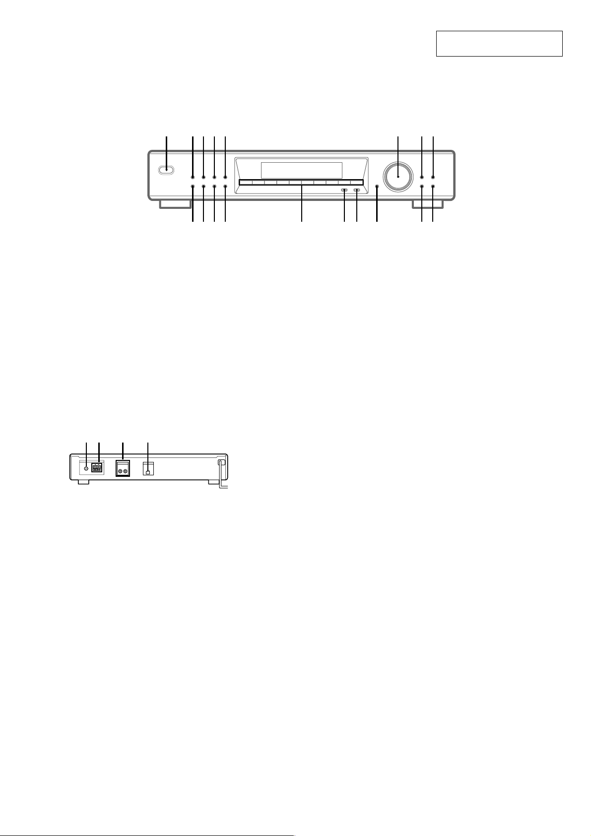
LOCATION OF CONTROLS
– Front Panel –
1 2 3 4 5 7 86
SECTION 1
GENERAL
1234567890
ST-SE570
This section is extracted from
instruction manual.
– Rear Panel –
3
2
1
ANTENNA
FM
75Ω COAXIAL
LINE OUT
AM
R L OUT
U
qk
AUTO BETICAL SELECT qk (7, 12)
BAND qg (9, 10, 12)
CHARACTER 7 (11)
DIRECT qs (9)
DISPLAY 5 (10, 11, 13)
ENTER qa (9, 11, 12, 14)
EON NEWS/INFO 3 (13, 14)
EON TA 2 (13, 14)
FM MODE qh (9, 10)
4
EON CONTROL
90qaqsqdqfqgqhqj
MEMORY 4 (8, 11)
MENU 0 (9, 11, 14)
Numeric buttons qf (7–9)
POWER 1 (7, 8, 12)
PTY qj (14, 15)
RETURN 9 (9)
SHIFT qd (8, 11)
TUNE MODE 8 (8, 10)
TUNING/SELECT 6 (7–12, 14)
1 FM ANTENNA terminal
2 AM ANTENNA terminals
3 LINE OUT jack
4 EON CONTROL OUT terminal
3
ST-SE570
)
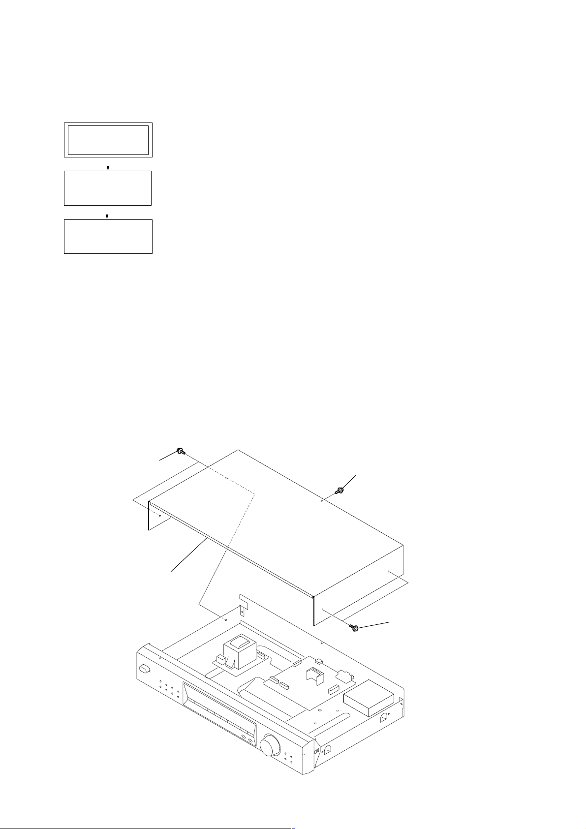
• This set can be disassembled in the order shown below.
2-1. DISASSEMBLY FLOW
SET
2-2. CASE (407026)
(Page 4)
2-3. MAIN BOARD
(Page 5)
SECTION 2
DISASSEMBLY
Note: Follow the disassembly procedure in the numerical order given.
2-2. CASE (407026)
1
two screws
(case 3 TP2)
4
case (407026)
3
screw
(case 3 TP2)
2
two screws
(case 3 TP2
4
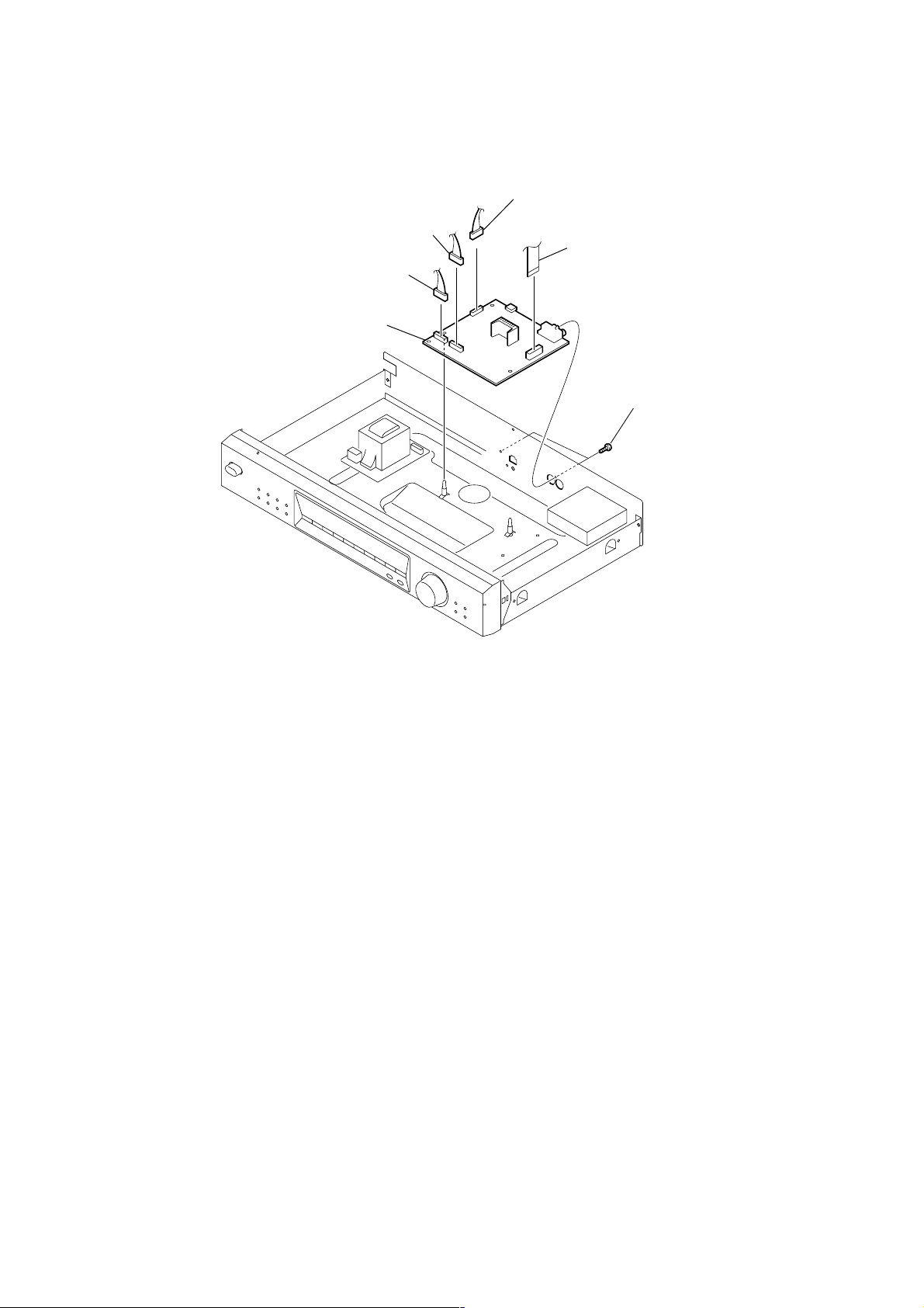
2-3. MAIN BOARD
)
2
connector (CNP702)
2
connector (CNP701)
4
MAIN board
2
connector (CNP952)
1
wire (flat type) (15 core
(CN101)
3
two screws
(BV/RING)
ST-SE570
5
ST-SE570
SECTION 3
TEST MODE
1. Circuit Check Mode
Set to the reception frequency that the circuit can STEREO RDS stations. (Set the input level to above 70 dB.)
This enables circuit check to be performed in any of the reception modes-FM, AM (MW, LW). Set to a desired band before setting the test
mode.
1. Turn OFF the power.
2. While pressing 4 and AUTO-BETICAL SELECT together, turn ON POWER .
• The items in the following table will be checked automatically in order every 2 seconds.
Display Items
Tuned
IF Frq
Sig Level
Stereo
RDS Signal
AST signal =LOW
IF COUNT OK
SI LEVELh70dB
ST signal=LOW
RDS DATA OK
FM RDS
OK or NG
OK or NG
OK or NG
OK or NG
OK or NG
DISPLAY
AM (MW, LW)
OK or NG
OK or NG
NG
IC201 NG, RV201 adjustments
TB101, IC201 NG
TB101 NG
TB101 NG
IC801 NG
NOTE : The preset data will be erased when this test mode is used. Therefore, take do wn the data before setting this mode and preset the data
again after completing operations in this mode.
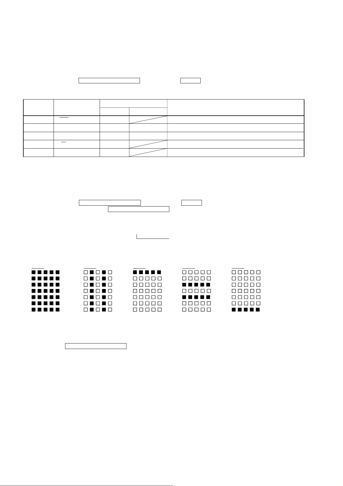
2. Display Tube Check and KEY Check mode
1. Turn OFF the power.
2. While pressing 1 and AUTO-BETICAL SELECT together, turn ON POWER .
3. While continuously pressing 1 and AUTO-BETICAL SELECT together, check the following.
Microcomputer version indication (1 sec) t All light up “7F” t Dot area only “60” t Dot area only “7E”
T
T
Dot area only “5F” T Dot area only “3D”
Indication test pattern
1 7F
2 60 3 7E
4 3D
5 5F
The display changes every 1 sec.
4. Release 1 and AUTO-BETICAL SELECT . The KEY CHECK mode will be set.
5. All key numbers will be displayed.
Key Number : 25
6. Each time the key is pressed, the key number will be counted down.
Each key will be counted only once, at the first time.
7. When all keys have been pressed, the process will end.
NOTE : As contents of the Factory Preset will be written into memory after completing this check mode, delete contents of memory
according to 4. Forced RESET.
6

ST-SE570
3. Entering the Factory Preset (In case perform just to write memory of the Factory Preset.)
1. Turn OFF the power.
2. While pressing 3 and AUTO-BETICAL SELECT together, turn ON POWER .
4. Forced RESET (Used to delete the contents of Factory Preset when it is written into the preset memory.)
Clears all the RAMs and sets the initial state
1. Turn OFF the power.
2. While pressing 5 and AUTO-BETICAL SELECT together, turn ON POWER .
3. When “All clear” is indicated on the fluorescent display tube, it means that “Forced Reset” has been completed.
5. Language Change
1. Turn OFF the power.
2. While pressing 2, turn ON POWER .
7
ST-SE570
SECTION 4
ELECTRICAL ADJUSTMENTS
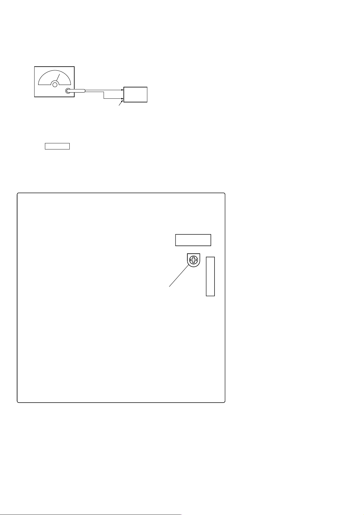
FM Signal Level Adjustment
FM RF signal
generator
set
Carrier frequency : 98 MHz
Modulation : 1 kHz, 40 kHz deviation
Output level : 6.3 mV (76dBµ)
(75
Ω
open)
Procedure:
1. Tune the set to 98 MHz.
2. Push the DISPLAY button for digital signal meter indication.
3. Adjust RV201 to the place where level and “70dB M” indication lights on fluorescent indicator tube.
Adjustment Location:
[MAIN BOARD] — Component Side —
FM ANTENNA
Ω
coaxial
75
(TB101)
RV201
FM SIGNAL LEVEL
Adjustment
IC201
CN101
8
 Loading...