

Page 1

4-233-395-17(1)
FM Stereo
FM-AM Tuner
Operating Instructions
Owner’s Record
The model and serial numbers are located on the rear panel. Record the serial number
in the space provided below. Refer to them whenever you call upon your Sony dealer
regarding this product.
Model No. Serial No.
ST-SE570
ST-SE370
© 2001 Sony Corporation
Page 2
WARNING
To reduce the risk of fire or electric
shock, do not expose this apparatus to
rain or moisture.
To avoid electrical shock, do not open
the cabinet. Refer servicing to qualified
personnel only.
Install this system so that the power cord can be
unplugged from the wall socket immediately in the
event of trouble.
To prevent fire, do not Cover the ventilation of the
apparatus with news papers, table-cloths, curtains,
etc. And don’t place lighted candles on the apparatus.
To prevent fire or shock hazard, do not place objects
filled with liquids, such as vases, on the apparatus.
Don’t throw a battery, dispose it as
the injurious wastes.
NOTICE FOR THE CUSTOMERS IN THE
U.S.A.
WARNING
This equipment has been tested and found to comply
with the limits for a Class B digital device, pursuant
to Part 15 of the FCC Rules. These limits are
designed to provide reasonable protection against
harmful interference in a residential installation. This
equipment generates, uses, and can radiate radio
frequency energy and, if not installed and used in
accordance with the instructions, may cause harmful
interference to radio communications. However, there
is no guarantee that interference will not occur in a
particular installation. If this equipment does cause
harmful interference to radio or television reception,
which can be determined by turning the equipment
off and on, the user is encouraged to try to correct the
interference by one or more of the following
measures:
– Reorient or relocate the receiving antenna.
– Increase the separation between the equipment and
receiver.
– Connect the equipment into an outlet on a circuit
different from that to which the receiver is
connected.
– Consult the dealer or an experienced radio/TV
technician for help.
CAUTION
You are cautioned that any changes or modifications
not expressly approved in this manual could void
your authority to operate this equipment.
Note to CATV system installer
This reminder is provided to call the CATV system
installer’s attention to Article 820-40 of the NEC that
provides guidelines for proper grounding and, in
particular, specifies that the cable ground shall be
connected to the grounding system of the building, as
close to the point of cable entry as practical.
This symbol is intended to alert the user to
the presence of uninsulated “dangerous
voltage” within the product’s enclosure that
may be of sufficient magnitude to constitute
a risk of electric shock to persons.
This symbol is intended to alert the user to
the presence of important operating and
maintenance (servicing) instructions in the
literature accompanying the appliance.
About This Manual
The instructions in this manual describe the
operation of the Sony ST-SE570 and
ST-SE370. Most operating procedures apply to
both. However, there are certain procedures
that may apply to only one of the tuners. These
are clearly indicated (e.g., ST-SE570 only).
Check the model number on the front of your
tuner so you’ll know which instructions apply
to you.
In this manual, the display of ST-SE570 is used
for illustration purposes.
2
Page 3

Table of Contents
Parts Identification
Main unit ............................................... 4
Getting Started
Unpacking ............................................. 5
Hooking up the system .......................... 5
Selecting the German display ................ 7
Storing FM stations automatically
(Auto-betical Select)* .....................7
Presetting radio stations.........................8
Basic Operations
Receiving preset stations ....................... 8
Advanced Tuner Operations
About the menu entry system ................ 9
Customizing the display ........................ 9
Receiving broadcasts ............................. 9
Tips for better FM reception ............... 10
Naming the preset stations .................. 11
Organizing the preset stations ............. 11
Using the Radio Data System (RDS)* ...
12
Additional Information
Precautions .......................................... 16
Troubleshooting...................................16
Specifications ...................................... 17
* European model only.
3
Page 4
Parts Identification
The items are arranged in alphabetical order.
Refer to the pages indicated in parentheses ( ) for details.
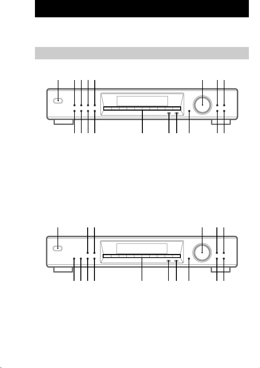
Main unit
ST-SE570
12345 786
1234567890
90qaqsqdqfqgqhqjqk
AUTO BETICAL SELECT qk (7, 12)
BAND qg (9, 10, 12)
CHARACTER 7 (11)
DIRECT qs (9)
DISPLAY 5 (10, 11, 13)
ENTER qa (9, 11, 12, 14)
EON NEWS/INFO 3 (13, 14)
EON TA 2 (13, 14)
FM MODE qh (9, 10)
ST-SE370
123 564
AUTO BETICAL SELECT (European model only)
qh (7, 12)
BAND qd (9, 10, 12)
CHARACTER 5 (11)
DIRECT 0 (9)
DISPLAY 3 (10, 11, 13)
ENTER 9 (9, 11, 12, 14)
FM MODE qf (9, 10)
MEMORY 2 (8, 11)
4
MEMORY 4 (8, 11)
MENU 0 (9, 11, 14)
Numeric buttons qf (7–9)
POWER 1 (7, 8, 12)
PTY qj (14, 15)
RETURN 9 (9)
SHIFT qd (8, 11)
TUNE MODE 8 (8, 10)
TUNING/SELECT 6 (7–12, 14)
1234567890
7890qaqsqdqfqgqh
MENU 8 (9, 11, 14)
Numeric buttons qs (7–9)
POWER 1 (7, 8, 12)
PTY (European model only) qg (14, 15)
RETURN 7 (9)
SHIFT qa (8, 11)
TUNE MODE 6 (8, 10)
TUNING/SELECT 4 (7–12, 14)
Page 5
Getting Started
Unpacking
Check that you received the following items
with the tuner:
• Audio cord (1)
• AM loop antenna (1)
• FM wire antenna (1)
• EON connecting cord (ST-SE570 only, 1)
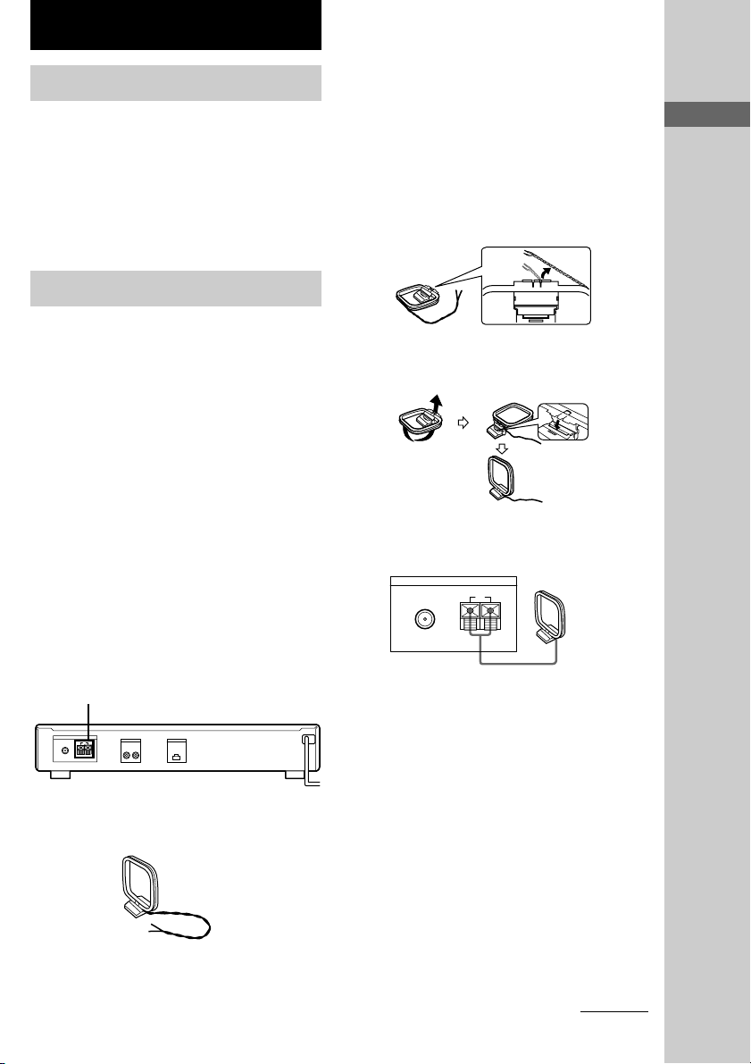
Hooking up the system
1 Before assembling the supplied
antenna, pull the lead wire out from the
slot in the antenna frame.
2 Unwrap 3 lengths of the braided lead
wire from around the frame of the
antenna.
Be careful to unwrap only the braided
section of the lead wire. Do not unwrap
more than 3 lengths of the lead wire. Also,
be careful not to unbraid the lead wire.
Parts Identification/Getting Started
Before you get started
• Turn off the power to all components before
making any connections.
• Do not connect the mains lead until all of the
connections are completed.
• Be sure to make connections firmly to avoid
hum and noise.
• When connecting an audio cord, be sure to
match the colour-coded pins to the appropriate
jacks: White (left) to White; and Red (right) to
Red.
AM antenna hookups
This section describes how to connect the
supplied AM loop antenna. For the specific
location of the AM ANTENNA terminals, see
the illustration below.
AM ANTENNA
ANTENNA
FM
75Ω COAXIAL
What will I need?
• AM loop antenna (supplied) (1)
OUTPUT
R L OUT
EON CONTROL
AM
y
3 Assemble the supplied antenna as
shown below.
4 Connect the AM loop antenna to the AM
terminals on the back of this unit.
FM
75Ω COAXIAL
ANTENNA
y
AM
AM loop antenna
5 Adjust the antenna direction for the
best reception.
The AM loop antenna has a directivity
which detects the signal from some angles
more strongly than others. Set the antenna
to the orientation which provides the best
receiving condition.
If a high pitched noise (beat noise) occurs
when recording AM broadcasts, adjust the
position of the AM loop antenna so that the
noise disappears.
If you live in a building constructed of
reinforced concrete, or with a steel frame,
you may not be able to achieve good
reception since the radio waves become
weaker indoors. In this case, we recommend
connecting an optional antenna.
continued
5
Page 6
EON CONTROL
OUTPUT
ANTENNA
OUTPUT
EON CONTROL
FM
y
75Ω COAXIAL
R LOUT
AM
l
TUNER IN
RL
OUTPUT
R L
l
EON CONTROL
OUT
EON CONTROL
IN
Hooking up the system (continued)
Tip
For stations that are difficult to receive, try
repositioning the loop antenna while tuning. Placing
the supplied AM loop antenna near a window will
help improve reception quality.
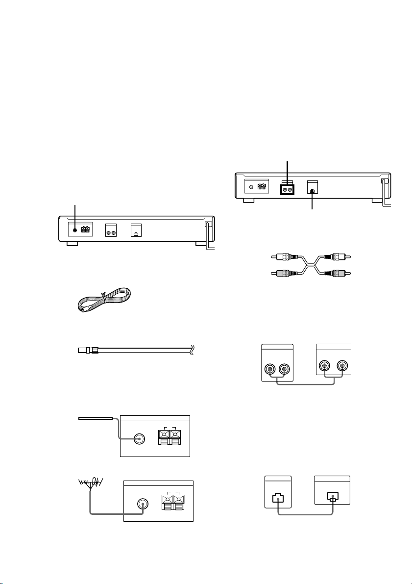
FM antenna hookups
With an FM outdoor antenna, you can obtain a
higher FM broadcast sound quality. We
recommend that you use the supplied FM wire
antenna only temporarily until you install an
FM outdoor antenna. For the specific location
of the FM ANTENNA terminal, see the
illustration below.
FM ANTENNA
Connecting a ground wire
If you connect an outdoor antenna, be sure to
connect a earth lead (not supplied) to the AM
ANTENNA U terminal (in addition to the AM
loop antenna) for lightning protection.
Amplifier hookups
Connect the tuner to an amplifier. Be sure to
turn off both components before connection.
For the specific location of the terminals, see
the illustration below.
ANTENNA
FM
75Ω COAXIAL
OUTPUT
R L OUT
EON CONTROL
AM
y
What will I need?
• FM wire antenna (supplied) (1)
• FM outdoor antenna (not supplied) (1) and
75-ohm coaxial cable with IEC female type
connector (not supplied) (1)
IEC female type connector
Connect the supplied FM wire antenna or an
FM outdoor antenna (not supplied) to one of
the FM terminals on the back of this unit.
FM wire antenna
FM outdoor antenna
FM
75Ω COAXIAL
FM
ANTENNA
AM
y
ANTENNA
AM
What cables will I need?
• Audio cord (supplied) (1)
White (L) White (L)
Red (R) Red (R)
Connect the white plugs to the white (L) jacks
and the red plugs to the red (R) jacks. Insert the
plugs completely into the jacks; incomplete
connections may cause noise.
Tuner Amplifier
Tip (ST-SE570 only)
If you have a Sony amplifier equipped with an EON
CONTROL IN terminal, use the supplied EON
connecting cord to connect the EON CONTROL
OUT terminal on the tuner to the EON CONTROL
IN terminal on your amplifier. This lets you use the
EON function (see page 13) when listening to other
components.
Tuner Amplifier
6
IEC female type connector
75Ω COAXIAL
y
Page 7

Mains lead hookup
Connect the mains lead to a wall outlet after
completing all of the previous connections.
ANTENNA
FM
75Ω COAXIAL
AM
y
OUTPUT
EON CONTROL
R LOUT
To a wall outlet
Selecting the German display
You can select either an English or a German
language display. The factory preset language
is English. To change the display to German,
follow the steps below.
1 Press POWER to turn off the tuner.
2 While pressing down the numeric
button 2, press POWER to turn on the
tuner.
“Deutsch” appears in the display.
To return to the English display
Repeat this procedure.
“English” appears in the display.
Storing FM stations
automatically
1 Press POWER to turn on the tuner.
2 Turn on the amplifier and select the
TUNER mode.
3 Press AUTO BETICAL SELECT.
“Yes” and “No” appear in the display.
4 Turn TUNING/SELECT to select “Yes”.
5 Press AUTO BETICAL SELECT again.
The tuner scans and stores all the FM and
FM RDS stations in the broadcast area.
For RDS stations, the tuner first checks for
stations broadcasting the same programme,
then stores only the one with the clearest
signal. The selected RDS stations are sorted
alphabetically by their Programme Service
name, then assigned a two-character preset
code. For more details on RDS, see page 12.
Regular FM stations are assigned twocharacter preset codes and stored after the
RDS stations.
Tip
To change the location of, or erase, a preset station,
see “Organizing the preset stations” on page 11.
Notes
• If you move to another area, repeat this procedure
to store stations in your new area.
• For details on tuning stored stations, see page 8.
• The FM MODE setting is also stored along with the
station.
• If you move the antenna after storing stations using
Auto-betical Select, the stored settings may no
longer be valid. If this happens, store the stations
again.
Getting Started
(Auto-betical Select)
(European model only)
With Auto-betical Select you can automatically
store up to 30 FM and FM RDS stations in
alphabetical order without redundancy.
Additionally, Auto-betical Select only stores
the stations with the clearest signals. If you
want to store FM or AM (MW and LW)
stations one by one, see “Presetting radio
stations” on page 8 and “Receiving broadcasts”
on page 9.
7
Page 8

Basic Operations
Presetting radio stations
This section shows you how to store up to 30 of
your favorite FM or AM (FM, MW or LW:
European model) stations manually onto preset
codes made up of characters (A, B, or C) and
numbers (1 - 0), such as A7. You can store up
to 10 stations on each of the 3 different letters.
You can use these letters to classify stations
according to music category or station band.
1 Tune in the FM or AM (MW and LW)
station you want to store (see
“Receiving broadcasts” on page 9).
2 Press MEMORY.
“MEMORY” appears along with the lowest
vacant code to indicate that the tuner is
ready to store the station.
3 Press SHIFT repeatedly to select either
A, B, or C.
The letter you selected appears in the
display.
4 Press a numeric button (1 - 0).
The tuner stores the station at the preset
code you specified.
5 Repeat steps 1 through 4 to store other
stations.
Tips
• When you preset an RDS station broadcasting
station name information, the station name is
automatically stored at the station preset (European
model only).
• If you want to label the stations, follow the
procedure described in “Naming the preset stations”
on page 11.
Receiving preset stations
1 Make sure you’ve hooked up the tuner
and preset stations.
(See pages 5 - 7 for hookups and page 7 or
this page for presetting.)
2 Turn on the amplifier and select the
TUNER mode.
3 Press POWER to turn on the tuner.
4 Press SHIFT repeatedly to select A, B,
or C.
5 Press the preset number you want (1 -
0).
To check broadcasts by scanning
the preset stations
1 Press TUNE MODE repeatedly so that
“PRESET” appears in the display.
2 Turn TUNING/SELECT.
Each time you turn TUNING/SELECT, a
preset station is received and the settings
(preset code, frequency, and station name,
etc.) appear in the display. The signal meter
indicates the strength of the broadcast
signal.
Tip
To tune in a non-preset station, see “Receiving
broadcasts” on page 9.
8
Page 9

Advanced Tuner Operations
About the menu entry system
This tuner uses a menu entry system which
allows you to operate various functions by
following messages on the display. Use the
following controls for menu operation.
Use
MENU
TUNING/SELECT
ENTER
RETURN
To
Enter the menu mode.
Display different items or
settings.
Select the currently displayed
item or setting.
Return to a previous stage in
the menu mode.
Customizing the display
You can select the appearance of the display
from one of the following four display modes.
1 Press MENU, then turn TUNING/
SELECT until “Disp-Mode” appears in
the display.
2 Press ENTER.
“Select” appears in the display.
3 Turn TUNING/SELECT to select a
display mode.
Full Display/Full Brightness t Full
Display/Dimmed t Minimal Display/Full
Brightness t Minimal Display/Dimmed
4 Press ENTER.
The setting remains in effect until you
change it again.
If you press one of the buttons on this unit,
the minimal display changes to the full
display with the selected brightness. After
about 4 seconds, the display returns to the
display mode you selected.
Receiving broadcasts
This tuner lets you enter a station’s frequency
directly by using the numeric buttons (Direct
Tuning). If you do not know the frequency of
the station you want, see “Receiving broadcasts
by scanning stations (Automatic Tuning)” on
page 10.
Before you begin, make sure you have
connected an FM/AM antenna to the tuner as
indicated on pages 5 and 6.
1 Press BAND repeatedly to select FM or
AM (MW and LW).
2 Press DIRECT.
3 Press the numeric buttons to enter the
frequency.
Example 1: FM 102.50 MHz
1 0250
Example 2: AM 1350 kHz
1 350
To receive other stations
Repeat steps 1 to 3.
Tips
• When you tune in AM (MW and LW) stations,
adjust the direction of the AM loop antenna for
optimum reception.
• If the STEREO indicator remains off, press FM
MODE when an FM stereo broadcast is received.
• If you cannot tune in a station and the entered
numbers are flashing, make sure you have entered
the right frequency. If not, press DIRECT and
reenter the frequency you want. If the entered
numbers are still flashing, the frequency is not used
in your area.
• If you enter a frequency not covered by the tuning
interval, the entered value is automatically rounded
up or down to the closest covered value.
Tuning intervals for direct tuning are:
FM:
U.S. models: 100 kHz intervals
Other models: 50 kHz intervals
AM:
U.S. models: 10 kHz intervals
Other models: 9 kHz intervals (MW),
1 kHz interval (LW)
Basic Operations/Advanced Tuner Operations
Advanced Tuner Operations
continued
9
Page 10

Receiving broadcasts (continued)
Tips for better FM
Receiving broadcasts by
scanning stations (Automatic
Tuning)
With automatic tuning, you can quickly tune in
a station without having to know its frequency.
1 Press BAND repeatedly to select either
FM or AM (MW and LW).
2 Press TUNE MODE so that “AUTO
TUNING” (“AUTO” for ST-SE370)
appears in the display.
3 Turn TUNING/SELECT slightly and
release it when the frequency numbers
start changing.
Turn the control to the right for a higher
frequency; turn it to the left for a lower frequency.
When the tuner locates a station, it stops
automatically. “TUNED” appears in the display.
The signal meter indicates the strength of the
broadcast signal.
4 Repeat step 3 until you tune in the
appropriate station.
To store the station, see “Presetting radio
stations” on page 8.
If you cannot tune in the station you
want (Manual Tuning)
With manual tuning, you can search through all
stations broadcasting on each band, and tune in
stations with extremely weak signals that you might
not be able to receive with automatic tuning.
1 Press BAND repeatedly to select FM or AM
(MW and LW).
2 Press TUNE MODE so that only “TUNING”
appears in the display (ST-SE570 only).
“AUTO” should not appear in the display.
For ST-SE370, press TUNE MODE until
nothing appears in the display.
3 Turn TUNING/SELECT until you tune in the
station you want.
Turn the control to the right for a higher
frequency; turn it to the left for a lower frequency.
The signal meter indicates the strength of the
broadcast signal.
Note
When you reach the highest or lowest frequency of
any band, tuning stops.
10
reception
This tuner has various functions designed for
better reception. First, try to receive stations
with the standard settings. If the reception is
not good, try altering the reception quality to
obtain a clear signal. The tuner stores the
following adjustments, together with the
frequency when you make a station preset.
Setting the FM mode
Press FM MODE a few times to select the
reception mode, select either Auto stereo (no
indication) or “MONO”.
• Auto stereo mode receives stereo broadcasts
with strong signals. Press FM MODE a few
times so that “MONO” disappears.
• “MONO” receives stations with weak signals.
Stations will be received in monaural but with
even less noise.
Checking the signal strength
You can use the digital signal meter to check
the signal strength of FM frequencies. The
display range is from 16 to 70 dB (1 µV of
radio frequency voltage = 0 dB). To obtain a
signal to noise ratio sufficient for receiving a
stereo broadcast, we recommend a reading
greater than 50 dB. (You can also change the
FM MODE while using the signal meter to
determine the best reception.)
1 Tune in an FM station.
2 Press DISPLAY repeatedly to display
the digital signal meter.
3 Rotate the FM antenna to obtain the
strongest signal.
Page 11

Naming the preset
Organizing the preset
stations
You can assign a name up to 5 characters long
to each preset station except FM RDS stations.
When the station is tuned in, the station name
will appear instead of the frequency.
1 Press CHARACTER.
The cursor flashes in the display.
2 Turn TUNING/SELECT to select a
character.
3 When the character you want appears,
press CHARACTER to move the cursor
into position for the next character.
If you make a mistake
Press CHARACTER repeatedly until the
character you want to change flashes (every
time you press CHARACTER, the next
character flashes). Then turn TUNING/
SELECT to select a new character.
4 Repeat steps 2 and 3 until the station
name you want appears in the display.
5 Press MEMORY.
“MEMORY” appears along with the lowest
vacant code to indicate that the tuner is
ready to store the station.
6 Press SHIFT and one of the preset
buttons to specify the preset where you
want to store the station name.
Note
The display returns to normal display mode if you
stop assigning names for more than 8 seconds. If this
happens, start again from the beginning.
Tip
To see the frequency of the displayed station name,
press DISPLAY repeatedly.
stations
This tuner makes it easy to arrange preset
stations in the order you prefer. You can
arrange all the preset stations automatically,
according to alphabetical order, signal strength,
country code, or tuner band, or you can use the
Move and Erase functions to move and erase
specific preset stations.
1 Press MENU.
2 Turn TUNING/SELECT until “Edit”
appears in the display and press
ENTER.
If no stations have been stored as presets,
“No Preset” appears in the display.
3 Turn TUNING/SELECT to select one of
the following sorting methods:
Select To
Move Change the location of a specific
Erase Erase a specific preset (see page 12).
Alphabet Sort preset stations in alphabetical
Strength Sort preset stations in order of their
Country* Sort FM RDS stations with PI**
Band Sort preset stations in order of their
* European model only.
**Programme Identification (See page 13).
4 Press ENTER.
The tuner sorts the stations, then returns to
normal tuning mode and receives preset
station A1.
Note
Some countries use the same country code, and the
stations from these counties may be arranged
together.
preset (see page 12).
order according to their preset names.
Stations without preset names are
arranged by frequency, from low to
high.
signal strength (FM stations only).
AM (MW and LW) stations are
arranged by frequency.
information alphabetically by
country. Other stations are arranged
by frequency.
frequency band (FM - AM (MW LW)).
continued
Advanced Tuner Operations
11
Page 12

Organizing the preset stations
(continued)
Moving preset station
You can also move a specific preset station.
1 Follow steps 1 through 3 in “Organizing
the preset stations” and select “Move”
from the Edit menu, then press ENTER.
2 Turn TUNING/SELECT so that the
preset code you want to move appears
in the display and press ENTER.
3 Turn TUNING/SELECT to select the new
location for the preset code and press
ENTER.
The preset station you selected is moved to
the new location and the other preset
stations in that group (“A” for example)
shift backwards to make room for the new
preset.
Example: If you move A4 to A1.
A1 A2 A3 A4 A5 A6 A7 A8Preset
89.5 94.5 96.5 98.0 100.5 103.0 104.5 106.0Frequency
.
A1 A2 A3 A4 A5 A6 A7 A8Preset
98.0 89.5 94.5 96.5 100.5 103.0 104.5 106.0Frequency
Erasing preset stations
You can erase preset stations one by one.
1 Follow steps 1 through 3 in “Organizing
the preset stations” and select “Erase”
from the Edit menu, then press ENTER.
2 Turn TUNING/SELECT so that the
preset code you want to erase appears
in the display and press ENTER.
The preset station you selected is erased
from the preset memory and the other preset
stations in that group (“A” for example)
shift forward to fill in the blank space.
Example: If you erase A1.
A1 A2 A3 A4 A5 A6 A7 A8Preset
89.5 94.5 96.5 98.0 100.5 103.0 104.5 106.0Frequency
.
A1 A2 A3 A4 A5 A6 A7 A8Preset
94.5 96.5 98.0 100.5 103.0 104.5 106.0Frequency
Tip
If you want to erase all the preset stations:
1Turn off the tuner.
2While pressing down the numeric button 5 and
AUTO BETICAL SELECT (ST-SE570) or BAND
(ST-SE370), press POWER to turn on the tuner.
Using the Radio Data System (RDS)
(European model only)
What you can do with RDS
The Radio Data System (RDS) is a
broadcasting service that allows radio stations
to send additional information along with the
regular radio programme signal. This tuner
offers you three convenient RDS features:
Displaying the RDS information; Monitoring
traffic, news, or information programmes; and
Locating a station by programme type. RDS is
available only on FM stations.*
Note
RDS may not work properly if the station you tuned
to is not transmitting the RDS signal properly or if the
signal strength is weak.
* Not all FM stations provide RDS service, nor do
they provide the same types of services. If you are
not familiar with the RDS system, check with your
local radio stations for details on RDS services in
your area.
Receiving RDS broadcasts
Simply select a station from the FM band.
When you tune in a station that provides RDS
services, the RDS indicator and the station
name appears in the display.
12
Page 13

Displaying the RDS
information
Press DISPLAY repeatedly until the
information you want is displayed.
Information
displayed
Station Name*
Frequency*
Clock Time
(24 hour system)
Programme Type
Radio Text
Programme
Identification
Digital signal meter*
* This information also appears for non-RDS FM
stations.
Notes
• If there is an emergency announcement by
governmental authorities, “ALARM” flashes in the
display.
• If a station is not providing a particular RDS
service, “NO...” (such as “NO PTY”) appears in the
display.
• When a station broadcasts radio text data, the
display shows the data at the rate it is sent from the
station. The display speed changes in relation to the
speed at which the data is sent.
You can
Locate each station by name
(e.g., WDR) instead of
frequency.
Locate each station by
frequency.
Display the current time.
Locate a specific type of
programme being broadcast.
(See page 14 for the types of
programmes you can select.)
Display the text messages sent
by the RDS station.
Determine each broadcast's
country of origin.
Check the signal strength of
FM frequencies. (See page 10
for details.)
Monitoring traffic, news, or
information programmes
(EON)
(ST-SE570 only)
Enhanced Other Networks (EON) allows the
tuner to automatically switch to a station
broadcasting traffic, news, or information.
After the programme ends, the tuner switches
back to the station you were listening to. To use
this function, be sure to store the stations
beforehand.
To monitor traffic programmes
1 Tune to a preset FM RDS station so that
the RDS TP, or RDS TP EON indicators
light in the display.
2 Press EON TA so that “TA” appears in
the display.
Each time you press EON TA, the display
changes as follows:
TA (Traffic Announcement) y OFF
When the tuner automatically tunes in a
traffic programme, the TA indicator flashes.
If you do not want to listen to the entire
programme, press EON TA to switch back
to the original station.
To monitor news and/or information
programmes
1 Tune to a preset FM RDS station so that
the RDS TP or RDS TP EON indicators
light in the display.
2 Press EON NEWS/INFO so that either
“NEWS”, “INFO”, or “NEWS/INFO”
appear in the display.
Each time you press EON NEWS/INFO, the
display changes cyclically as follows:
NEWS t INFO t NEWS/INFO t OFF
When the tuner automatically tunes in a
news or information programme, the
respective indicator flashes. If you do not
want to listen to the entire programme, press
EON NEWS/INFO to switch back to the
original station.
Advanced Tuner Operations
continued
13
Page 14

Using the Radio Data System (RDS)
(continued)
To stop monitoring the programme
Press EON TA or EON NEWS/INFO while the
tuner is in the respective EON standby mode
and the indicator goes off.
Notes
• If you tune in an AM (MW and LW) station or an
FM station which does not provide the RDS service,
the selected indicator (TA, NEWS, INFO, or
NEWS/INFO) goes off and the tuner does not
standby for EON stations.
• “Weak Signal” appears when the selected station
has a weak signal. “Return” appears when the tuner
is trying to retune a station with a weak signal.
• Turn off the EON feature when you want to record
a programme without interruptions, especially when
you want to do timer recording.
• “No EON” appears in the display if you select an
EON programme before tuning to an RDS station.
• If you make EON CONTROL connections to a
compatible Sony amplifier, the amplifier
automatically switches the function mode to
TUNER whenever the tuner receives a programme
you are monitoring.
Locating traffic programmes
(TA Search)
You can have the tuner locate stations currently
broadcasting traffic programme from among
the RDS stations stored in the tuner’s preset
memory.
1 Press MENU.
2 Turn TUNING/SELECT until “Traffic”
appears in the display and press
ENTER.
The unit enters search mode (“Search” and
“Traffic” appear alternately in the display).
When the tuner finds a traffic
announcement, it stops searching. The tuner
receives each station for 8 seconds.
3 Press ENTER when the tuner receives
the station you want to listen to that
programme.
Locating a station by
programme type (PTY)
You can locate a station you want by selecting
a programme type. The tuner tunes in the type
of programmes currently being broadcast from
the RDS stations stored in the tuner’s preset
memory.
1 Press PTY.
2 Turn TUNING/SELECT to select the
programme type you want.
See the following table for the programme
types you can select.
Programme
type
(Current) Affairs
Alarm
Alarm Test
Children (’s
programmes)
Country Music
Culture
Documentary
Drama
Education
Finance
Folk Music
Information
Jazz Music
What you hear
Topical programmes that
expand on current news
Emergency broadcasts
Used only for dynamic
switching
Programmes for the young
Country music programmes
Programmes about national or
regional culture, such as
language and societal concerns
Investigative features
Radio plays and serials
Educational programmes, such
as “how-to” and advice
programmes
Stock market reports and
trading, etc.
Folk music programmes
Programmes offering
information on a wide spectrum
of subjects, including consumer
affairs and medical advice
Jazz programmes
14
Page 15

Programme
type
Leisure
L (ight).
Classical
Easy Music
National Music
News
Oldies Music
Other Music
Phone In
Pop Music
PTY undefined
Religion
Rock Music
Science
Social A (ffairs)
Sport
S (erious).
Classical
Travel
Varied
Weather
What you hear
Programmes on recreational
activities such as gardening,
fishing, cooking, etc.
Classical music, such as
instrumental, vocal, and choral
works
Easy Listening (middle of the
road music)
Programmes featuring the
popular music of the country or
region
News programmes
Programmes featuring oldies
music
Music that does not fit into any
of the above categories, such as
Rhythm & Blues and Reggae
Programmes where members of
the public express their views
by phone or in a public forum
Popular music programmes
Any programmes not defined
above
Programmes of religious
content
Rock music programmes
Programmes about the natural
sciences and technology
Programmes about people and
the things that affect them
Sports programmes
Performances of major
orchestras, chamber music,
opera, etc.
Programmes about travel. Not
for announcements that are
located by TP/TA
Other types of programmes
such as, celebrity interviews,
panel games, and comedy
Weather information
3 Press PTY.
The tuner starts searching the preset RDS
stations for the programme (“Search” and
the programme type are displayed
alternately).
When the tuner finds the programme you
are looking for, it stops searching. The
preset stations currently broadcasting the
selected programme type are indicated and
the tuner receives each station for
8 seconds.
4 Press PTY when the tuner receives the
station you want to listen to that
programme.
Advanced Tuner Operations
15
Page 16

Additional Information
Precautions
On safety
• Should any liquid or solid object fall into the unit,
unplug the unit and have the unit checked by
qualified personnel before operating it any further.
• The unit is not disconnected from the AC power
source (mains) as long as it is connected to the wall
outlet, even if the unit itself has been turned off.
On power sources
• Before operating the unit, be sure that the operating
voltage of your unit is identical with that of your
local power supply.
• Unplug the unit from the wall outlet if it is not to be
used for an extended period of time. To disconnect
the cord, pull it out by grasping the plug. Never
pull the cord itself.
• AC power cord must be changed only at the
qualified service shop.
On placement
• Place the unit in a location with adequate
ventilation to prevent heat buildup and prolong the
life of its components.
• Do not place the unit near heat sources, or in a place
subject to direct sunlight, excessive dust or
mechanical shock.
• Do not place anything on top of the cabinet which
might block the ventilation holes and cause
malfunctions.
• Do not install the appliance in a confined space,
such as a bookcase or built-in cabinet.
On cleaning the cabinet
Clean the cabinet, panels and controls with a soft
cloth lightly moistened with a mild detergent solution.
Do not use any type of abrasive pad, scouring powder
or solvent such as alcohol or benzine.
On repacking
Do not throw away the carton and the packing
material. This makes an ideal container when
transporting the unit. When shipping the unit, repack
it as it was packed at the factory.
If you have any question or problem
concerning your unit that is not covered in this
manual, please consult your nearest Sony
dealer.
Troubleshooting
If you experience any of the following
difficulties while using the tuner, use this
troubleshooting guide to help you remedy the
problem. Should any problem persist, consult
your nearest Sony dealer.
There is no sound.
• Connect the aerials.
• Set the source setting on the amplifier to
TUNER.
You cannot tune in a frequency.
• Adjust the position of the aerial.
• Connect an external aerial for FM broadcasts.
• Preset the stations again if you have moved.
There is severe hum and/or background noise.
• Adjust the position or direction of the aerial.
• Tune to a correct frequency.
• Connect an external aerial for FM broadcasts.
• Move the tuner away from the source of the
noise.
RDS is not working (European model only).
• Make sure that you tune to an FM station.
• Select a stronger FM station.
“No Preset” appears in the display.
• If the mains lead is disconnected from the wall
outlet for more than one month, the memory is
erased. Preset stations again.
The station was interrupted by another station /
The tuner automatically starts searching
stations (ST-SE570 only).
• The EON function is working. Turn off EON
when you do not want the current programme
interrupted.
The appropriate display or information does not
appear.
• Turn off the tuner. Press down the numeric
button 5 and AUTO BETICAL SELECT
(ST-SE570) or BAND (ST-SE370), then press
POWER to turn the tuner back on. This empties
any frequencies stored in the preset memory and
returns the display to the default language
(English).
• Contact the radio station and find out whether or
not they actually provide the service in question.
If so, the service may be temporarily out of
order.
16
Page 17

Specifications
FM tuner section
Frequency range 87.5 - 108.0 MHz
Aerial terminals 75 Ω, unbalanced
Intermediate frequency
Sensitivity at 26 dB quieting (mono)
Usable sensitivity (IHF)
S/N at 40 kHz deviation
Harmonic distortion 0.09% (mono),
Frequency response 30 Hz - 15 kHz
Separation 45 dB at 1 kHz
Selectivity at 400 kHz
Output at 40 kHz deviation
(U.S. models: 100 kHz
step, other models: 50 kHz
step)
U.S. models: F-TYPE
CONNECTOR,
other models: IEC-male
10.7 MHz
10.3 dBf, 0.9 µV/75 Ω
at 46 dB quieting (stereo)
38.5 dBf, 23 µV/75 Ω
10.3 dBf, 0.9 µV/75Ω
74 dB (mono), 69 dB
(stereo)
0.18% (stereo)
(+0.5/–1.0 dB)
85 dB
at 300 kHz
70 dB
600 mV
AM tuner section
Frequency range
MW:
ST-SE570 522 - 1,611 kHz
ST-SE370
U.S. models: 530 - 1,710 kHz
Singaporean and Australian models:
Other models: 531 - 1,602 kHz
LW: 144 - 288 kHz
Intermediate frequency
Usable Sensitivity (with AM loop aerial)
MW: 200 µV/m
LW: 700 µV/m
Signal-to-noise ratio
MW: 54 dB
LW: 50 dB
Harmonic distortion 0.3% (50 mV/m,
Selectivity 50 dB
(9 kHz step)
(10 kHz step*)
531 - 1,710 kHz
(9 kHz step)
(9 kHz step)
(1 kHz step)
450 kHz
(50 mV/m, 999 kHz)
(50 mV/m, 216 kHz)
400 Hz)
General
Power requirements
U.S. models: 120 V AC, 60 Hz
Australian models: 230 V AC, 50 Hz
Other models: 230 V AC, 50/60 Hz
Power consumption 10 W
Dimensions 430 x 83 x 290 mm
Weight 2.5 kg
Supplied accessories
Audio cord (1)
AM loop antenna (1)
FM wire antenna (1)
EON connecting cord (ST-SE570 only, 1)
* (U.S. models only.) You can change the AM tuning
interval to 9 kHz. After tuning in any AM station,
turn off the tuner. Hold down the numeric button 9
and press the POWER button. To reset the scale to
10 kHz, hold down the numeric button 0 and press
the POWER button to turn on the tuner. All preset
stations will be erased when you change the tuning
interval.
(w/h/d)
Additional Information
Design and specifications are subject to change
without notice.
17
Page 18

18
Page 19

Additional Information
19
Page 20

Sony Corporation Printed in Malaysia
20
 Loading...