

Sony STSE-370 Service manual
ST-SE370
SERVICE MANUAL
Ver 1.0 2001.04
Photo: Black model
SPECIFICATIONS
FM tuner section
Frequency range 87.5 - 108.0 MHz
Aerial terminals 75 Ω, unbalanced
Intermediate frequency
Sensitivity at 26 dB quieting (mono)
Usable sensitivity (IHF)
S/N at 40 kHz deviation
Harmonic distortion 0.09% (mono),
Frequency response 30 Hz - 15 kHz
Separation 45 dB at 1 kHz
Selectivity at 400 kHz
Output at 40 kHz deviation
(U.S. models: 100 kHz
step, other models: 50 kHz
step)
U.S. models: F-TYPE
CONNECTOR,
other models: IEC-male
10.7 MHz
10.3 dBf, 0.9 µV/75 Ω
at 46 dB quieting (stereo)
38.5 dBf, 23 µV/75 Ω
10.3 dBf, 0.9 µV/75Ω
74 dB (mono), 69 dB
(stereo)
0.18% (stereo)
(+0.5/–1.0 dB)
85 dB
at 300 kHz
70 dB
600 mV
AM tuner section
Frequency range
MW:
U.S. models: 530 - 1,710 kHz
Singaporean and Australian models:
Other models: 531 - 1,602 kHz
LW: 144 - 288 kHz
Intermediate frequency
Usable Sensitivity (with AM loop aerial)
MW: 200 µV/m
LW: 700 µV/m
Signal-to-noise ratio
MW: 54 dB
LW: 50 dB
Harmonic distortion 0.3% (50 mV/m,
Selectivity 50 dB
(10 kHz step*)
531 - 1,710 kHz
(9 kHz step)
(9 kHz step)
(1 kHz step)
450 kHz
(50 mV/m, 999 kHz)
(50 mV/m, 216 kHz)
400 Hz)
US Model
AEP Model
UK model
E Model
Australian Model
General
Power requirements
U.S. models: 120 V AC, 60 Hz
Australian models: 230 V AC, 50 Hz
Other models: 230 V AC, 50/60 Hz
Power consumption 10 W
Dimensions 430 x 83 x 290 mm
Weight 2.5 kg
Supplied accessories
Audio cord (1)
AM loop antenna (1)
FM wire antenna (1)
* (U.S. models only.) You can change the AM tuning
interval to 9 kHz. After tuning in any AM station,
turn off the tuner. Hold down the numeric button 9
and press the POWER button. To reset the scale to
10 kHz, hold down the numeric button 0 and press
the POWER button to turn on the tuner. All preset
stations will be erased when you change the tuning
interval.
Design and specifications are subject to change
without notice.
(w/h/d)
9-873-833-11 Sony Corporation
2001D0500-1 Home Audio Company
C 2001.4 Shinagawa Tec Service Manual Production Group
FM STEREO FM-AM TUNER
ST-SE370
r
TABLE OF CONTENTS
1. GENERAL ................................................................... 3
2. DISASSEMBLY
2-1. Disassembly Flow ........................................................... 4
2-2. Case (407026) ................................................................. 4
2-3. MAIN Board ................................................................... 5
3. TEST MODE.............................................................. 6
4. ELECTRICAL ADJUSTMENTS......................... 8
5. DIAGRAMS
5-1. Note for Printed Wiring Boards and
Schematic Diagrams ....................................................... 9
5-2. Printed Wiring Boards – MAIN Section – ..................... 10
5-3. Schematic Diagram – MAIN Section –.......................... 11
5-4. Printed Wiring Boards – DISPLAY Section – ............... 12
5-5. Schematic Diagram – DISPLAY Section – .................... 13
5-6. IC Pin Function Description ........................................... 14
6. EXPLODED VIEWS
6-1. Case Section .................................................................... 15
6-2. Front Panel Section ......................................................... 16
6-3. Chassis Section ............................................................... 17
SAFETY CHECK-OUT
After correcting the original service problem, perform the following safety check before releasing the set to the customer:
Check the antenna terminals, metal trim, “metallized” knobs,
screws, and all other exposed metal parts for AC leakage.
Check leakage as described below.
LEAKAGE TEST
The AC leakage from any exposed metal part to earth ground and
from all exposed metal parts to any exposed metal part having a
return to chassis, must not exceed 0.5 mA (500 microamperes.).
Leakage current can be measured by any one of three methods.
1. A commercial leakage tester , such as the Simpson 229 or RCA
WT -540A. Follo w the manufacturers’ instructions to use these
instruments.
2. A battery-operated AC milliammeter. The Data Precision 245
digital multimeter is suitable for this job.
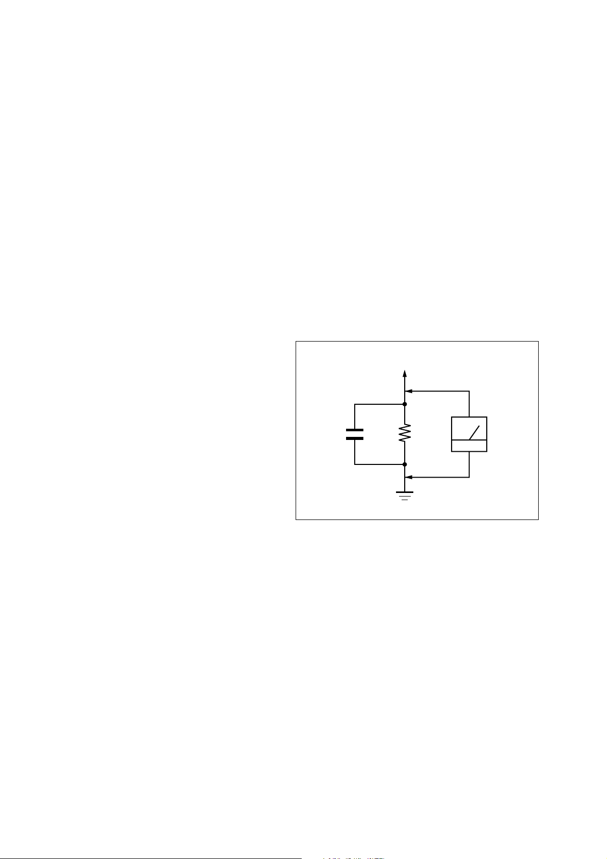
3. Measuring the voltage drop across a resistor by means of a
VOM or battery-operated AC voltmeter. The “limit” indication is 0.75 V, so analog meters must have an accurate lowvoltage scale. The Simpson 250 and Sanwa SH-63Trd are examples of a passive VOM that is suitable. Nearly all battery
operated digital multimeters that have a 2 V AC range are
suitable. (See Fig. A)
To Exposed Metal
Parts on Set
7. ELECTRICAL PARTS LIST ............................... 18
1.5 k
0.15 µF
Fig. A. Using an AC voltmeter to check AC leakage.
Ω
Earth Ground
AC
voltmete
(0.75 V)
SAFETY-RELATED COMPONENT WARNING!!
COMPONENTS IDENTIFIED BY MARK 0 OR DOTTED
LINE WITH MARK 0 ON THE SCHEMATIC DIA GRAMS
AND IN THE PARTS LIST ARE CRITICAL TO SAFE
OPERATION. REPLACE THESE COMPONENTS WITH
SONY PARTS WHOSE PART NUMBERS APPEAR AS
SHOWN IN THIS MANUAL OR IN SUPPLEMENTS PUBLISHED BY SONY.
2
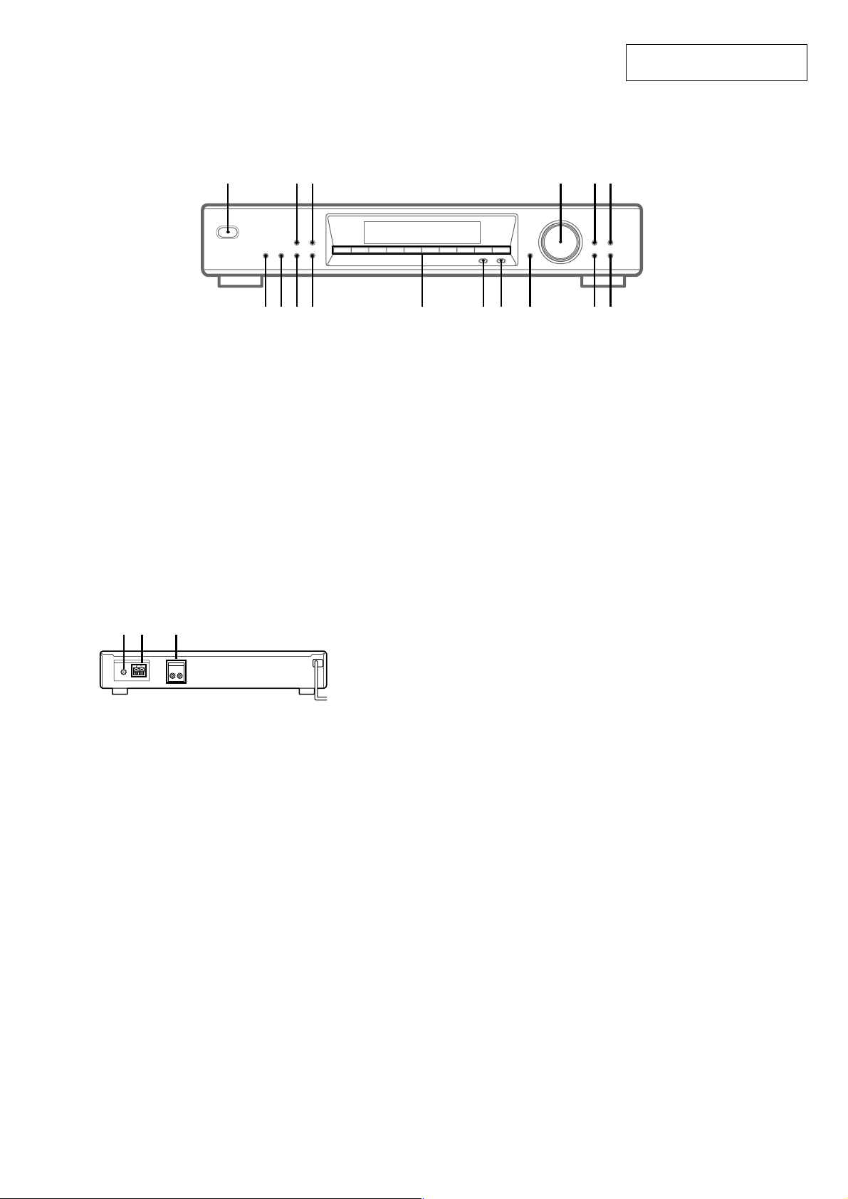
LOCATION OF CONTROLS
– Front Panel –
1 2 3 5 64
SECTION 1
GENERAL
1234567890
ST-SE370
This section is extracted from
instruction manual.
7890qaqsqdqfqgqh
AUTO BETICAL SELECT (European model only)
qh (7, 12)
BAND qd (9, 10, 12)
CHARACTER 5 (11)
DIRECT 0 (9)
DISPLAY 3 (10, 11, 13)
ENTER 9 (9, 11, 12, 14)
FM MODE qf (9, 10)
MEMORY 2 (8, 11)
– Rear Panel –
3
2
1
ANTENNA
FM
75Ω COAXIAL
LINE OUT
AM
R L
U
1 FM ANTENNA terminal
2 AM ANTENNA terminal
3 LINE OUT jack
MENU 8 (9, 11, 14)
Numeric buttons qs (7–9)
POWER 1 (7, 8, 12)
PTY (European model only) qg (14, 15)
RETURN 7 (9)
SHIFT qa (8, 11)
TUNE MODE 6 (8, 10)
TUNING/SELECT 4 (7–12, 14)
3
ST-SE370
)
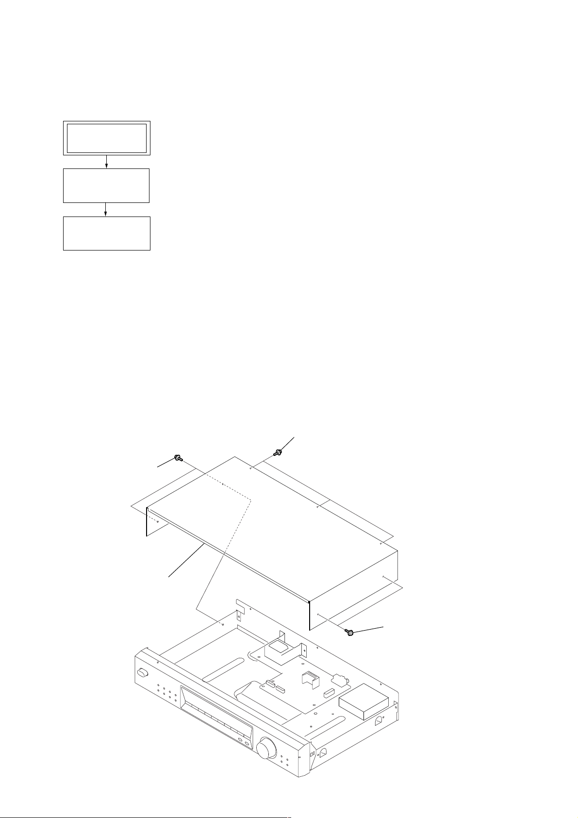
• This set can be disassembled in the order shown below.
2-1. DISASSEMBLY FLOW
SET
2-2. CASE (407026)
(Page 4)
2-3. MAIN BOARD
(Page 5)
SECTION 2
DISASSEMBLY
Note: Follow the disassembly procedure in the numerical order given.
2-2. CASE (407026)
1
two screws
(case 3 TP2)
4
case (407026)
3
three screws
(case 3 TP2)
2
two screws
(case 3 TP2
4
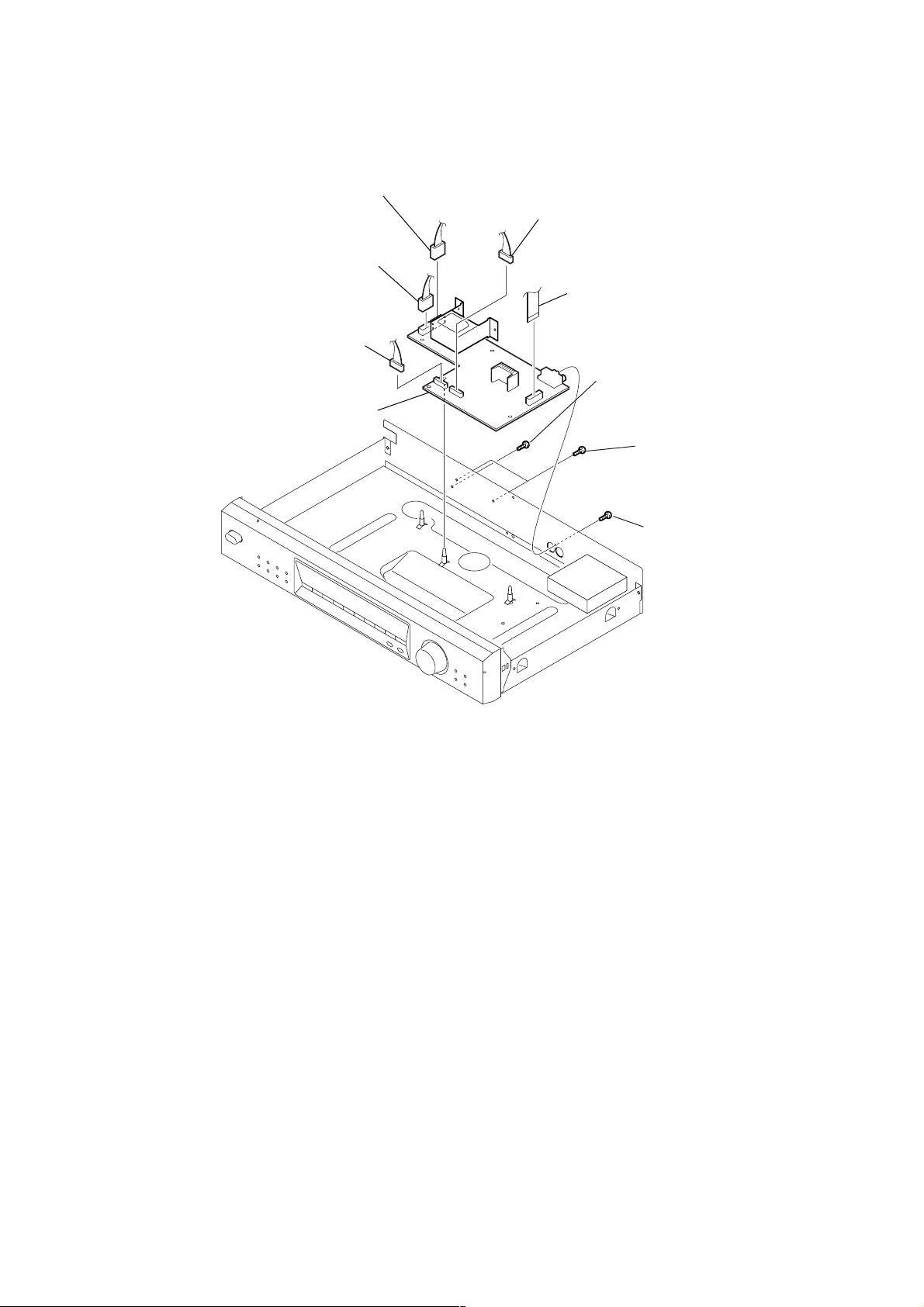
2-3. MAIN BOARD
)
2
2
connector (CNP951)
2
connector (CNP901)
connector (CNP701)
5
MAIN board
2
connector (CNP702)
1
wire (flat type) (15 core)
(CN101)
3
screw
(BVTP3 × 8 (S))
4
screw
(BVTT3 × 6 (S)
ST-SE370
3
screw
(BV/RING)
5
ST-SE370
SECTION 3
TEST MODE
NOTE : The preset data will be erased when this test mode is used. Therefore, take down the data before setting this mode and preset the data
again after completing operations in this mode.
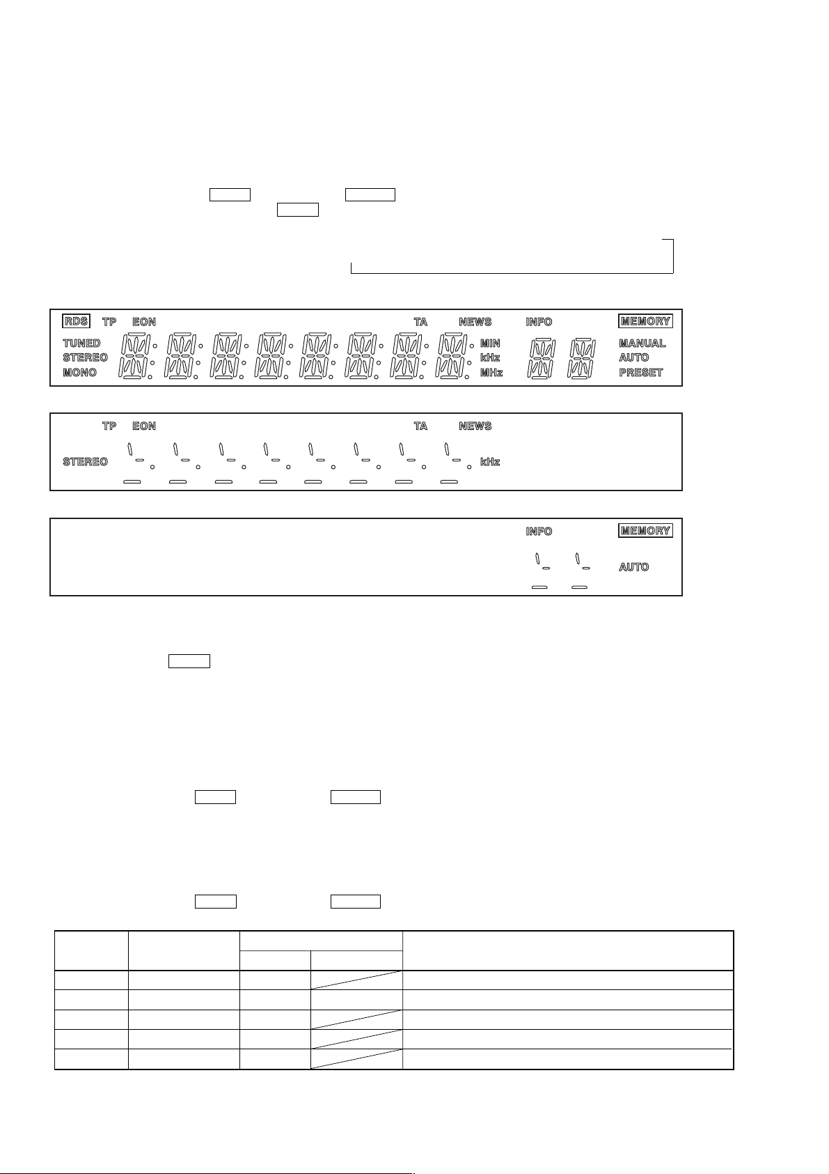
1. Display Tube and Key Check Mode
1-1. Display Tube Check
1-1-1. Turn OFF the power.
1-1-2. While pressing 1 and BAND together, turn ON POWER .
1-1-3. While continuously pressing 1 and BAND together, check the following.
Microcomputer version indication (1 sec) t All light up (1) t 8-digit test pattern (2) t 2-digit test pattern (3)
T
(1) All light up
(2) 8-digit test pattern
(3) 2-digit test pattern
The display changes every 500 msec.
1-2. Key Check
1-2-1. Release 1 and BAND . The KEY CHECK mode will be set.
1-2-2. All key numbers will be displayed. Key Number : 23
1-2-3. Each time the key is pressed, the key number will be counted down.
Each key will be counted only once, at the first time.
1-2-4. When all keys have been pressed, the process will end and the factory preset will be entered.
2. Entering the Factory Preset
To skip “1. Display Tube Key Check Mode”, and factory preset :
(1) Turn OFF the power.
(2) While pressing 3 and BAND together, turn ON POWER .
3. Circuit Check Mode
Set to the reception frequency that the circuit can receive (FM : STEREO, RDS stations). (Set the input level to above 70 dB.)
This enables circuit check to be performed in any of the reception modes-FM, AM (MW, LW). Set to a desired band before setting the test
mode.
(1) Turn OFF the power.
(2) While pressing 4 and BAND together, turn ON POWER .
• The items in the following table will be checked automatically in order every 2 seconds.
Display Items
TUNED
IF
SIG L
ST
RDS
AST signal = LOW
IF COUNT OK
SI LEVEL 70dB
ST signal = LOW
RDS DATA OK
FM RDS
OK or NG
OK or NG
>
=
OK or NG
OK or NG
OK or NG
DISPLAY
AM (MW, LW)
OK or NG
NG
IC201 NG, RV201 adjustments
TB101, IC201 NG
TB101 NG
TB101 NG
IC801 NG
6

4. Forced RESET
Clears all the RAMs and sets the initial state.
(1) Turn OFF the power.
(2) While pressing 5 and BAND together, turn ON POWER .
5. Language Change
1. Turn OFF the power.
2. While pressing 2 , turn ON POWER .
6. Change-over of AM Tuner Step between 9 kHz and 10 kHz (US model only)
• A step of AM channels can be changed over between 9 kHz and 10 kHz.
1. Turn OFF the power.
2. While pressing 9 or -, turn ON POWER .
ST-SE370
7
 Loading...