

Sony HT-SF2300, STR-KS2300 - Blu-ray Dvd Receiver Component, HT-SS2300 Operating Instructions Manual
SONY:
3-296-084-12(
1)
Home
Theatre
System
Operating
HT-SF2300
HT-SS2300
©2008 Sony Corporation
Instructions

Owner's Record
The model and serial numbers are locatedon the rear
of
the unit. Record the serial number in the space
provided below. Refer to them whenever you call
upon your Sony dealer regarding this product.
Model No. _
Serial No. _
WARNING
For
customers
States
Lt
CAUTION:TOREDUCE
REFER
in
,elll-Lh
RISK OF ELECTRIC
I
00
NOT REMOVE COVER (OR BACK).
NO USER·SERVICEABLE
SERVICINGTOOUALIFIED
$HOCt(
00
NOT OPEN •
THE
RISKOfELECTRIC
PARTS
SERVICE
the
I
INSIDE
PERSONNEL
United
SHOCI<,
To reduce the riskoffire or electric
shock, do not exposethis apparatusto
rain or moisture.
To reduce the riskoffire, do not cover the
ventilation opening
newspapers, tablecloths, curtain, etc.
Do not place the naked flame sources suchas lighted
candles on the apparatus.
To reduce the risk
expose this apparatus to dripping or splashing, and
do not place objects filled with liquids, such as
vases, on the apparatus.
Do not install the appliance in a confinedspace, such
as a bookcase or built-in cabinet.
As the main plug is used to disconnect the unit from
the mains, connect the unit
AC outlet. Should you notice an abnormality in the
unit, disconnect the main plug from the AC outlet
immediately.
Do not expose batteries or apparatus with batteryinstalled to excessive heat such as sunshine, fire or
the like.
of
the apparatus with
of
fire or electric shock, do not
to
an easily accessible
This symbol is intendedtoalert the
user to the presence of uninsulated
"dangerous voltage" within the
product's enclosure that may be
of
sufficient magnitude to constitute a
of
risk
This symbol is intended
electric shocktopersons.
to
alert the
user to the presence of important
operating and maintenance
(servicing) instructions in the
literature accompanying the
appliance.
WARNING
This equipment has been tested and found to comply
with the limits for a Class B digital device, pursuant
to Part
designed to provide reasonable protection against
harmful interference
This equipment generates, uses, and can radiate
radio frequency energy and,
in accordance with the instructions, may cause
harmful interference to radio communications.
However, there is
not occur in a particular installation. If this
equipment does cause harmful interference to radio
or television reception, which can be determined
turning the equipment
encouraged to try to correct the interference by one
or more
- Reorient or relocate the receiving antenna.
- Increase the separation between the equipment
- Connect the equipment into an outlet on a circuit
- Consult the dealer or an experienced
15ofthe FCC Rules. These limits are
in
a residential installation.
if
not installed and used
no
guarantee that interference will
off
and on, the user is
of
the following measures:
and receiver.
different from that to which the receiver is
connected.
radiorrV
technician for help.
by

CAUTION
You are cautioned that any changes or modification
not expressly approved
your authority to operate this equipment.
Note
This reminderisprovidedtocall CATV system
installer's attention to Article 820-40
that providesguidelinesfor proper grounding and, in
particular, specifies that the cable ground shall be
connected to the grounding system
as close to the point
For
to
CATV
customers
Disposal of Old Electrical &
Electronic Equipment
)t
(Applicable
• Union and other European
countries with separate
collection systems)
This symbol on the product or on its packaging
indicates that this product shall not be treated as
household waste. Instead it shall be handed over to
the applicable collection point for the recycling
electrical and electronicequipment. By ensuring this
product is disposed of correctly, you will help
prevent potential negative consequences for the
environment and human health, which could
otherwise be caused by inappropriate waste
handling
will help to conserve natural resources. For more
detailed information aboutrecycling
please contact your local Civic Office, your
household waste disposal service or the shop where
you purchased the product.
of
this product. The recyclingofmaterials
in
this manual could void
system
of
cable entry as practical.
installer:
of
of
the building,
in Europe
in
the European
of
this product,
the NEC
of
Disposal of waste batteries
)t
• countries with separate
(applicable
Union and other European
in
the European
collection systems)
This symbol on the battery or on the packaging
indicates that the battery provided with this product
shall not be treated
By ensuringthesebatteriesare disposed
you will help prevent potentially negative
consequences for the environment and human health
which could otherwise be caused by inappropriate
waste handling
materials will help
In case
data integrity reasons require a permanent
connection with an incorporated battery, this battery
should be replaced by qualified service staff only.
To ensure that the battery will be treated properly,
hand over the productatend-of-lifeto the applicable
collection point for the recycling
electronic equipment.
For all other batteries, please view the section on
how to remove the battery from the product safely.
Hand the battery over to the applicable collection
point for the recycling
For more detailed information about recycling
this product or battery, please contact your local
Civic Office, your household waste disposal service
or the shop where you purchased the product.
of
products that for safety, performance or
as
household waste.
of
correctly,
of
the battery. The recyclingofthe
to
conserve natural resources.
of
electrical and
of
waste batteries.
of
Notice for the customer in the
countries applying
The manufacturerofthis product is Sony
Corporation, 1-7-1 Konan Minato-ku Tokyo,
108-0075 Japan. The Authorized Representative for
EMC and product safety is Sony Deutschland
GmbH, Hedelfinger Strasse 61, 70327 Stuttgart,
Germany. For any service or guarantee matters
please refer to the addresses given
service or guarantee documents.
EU
Directives
in
separate
About
•
The
HT
models
purposes unless stated otherwise. Any difference
in operation is clearly indicated in the text, for
example, "Models
This
instructions in this manual are for model
-SF2300 andHT-SS2300. In this manual,
of
Manual
area code
CEL
of
area code
is used for illustration
CEL
only".
The HT-SF2300 consists of:
• Receiver STR-KS2300
• Speaker system
- Front speaker
-
Center
- Surround speaker
- Subwoofer
speaker
a
)
SS-MSP23F
SS-CNP23
SS-SRP23F
SS-WP23
The HT-SS2300 consists of:
• Receiver STR-KS2300
• Speaker system
-
Front
speaker
-
Center
- Surround speaker
- Subwoofer
a)
Be
sure to use only the supplied speakers.
speaker
a
)
SS-MSP23S
SS-CNP23
SS-SRP23S
SS-WP23
This receiver incorporates Dolby* Digital
Logic Surround and the DTS** Digital Surround
System.
* Manufactured under license from Dolby
Laboratories. Dolby, Pro Logic and the double-D
symbol are trademarks
** Manufactured under license under U.S. Patent
#'s:
5,451,942; 5,956,674; 5,974,380;
5,978,762; 6,487,535 &
worldwide patents issued
DTS Digital Surround are registered trademarks
andthe
DTS, Inc. © 1996-2007 DTS, Inc. All Rights
Reserved.
This receiver incorporates High-Definition
Multimedia Interface
HDMI, the HDMI logo and High-Definition
Multimedia Interface are trademarks or registered
trademarks
"x.v.Colour" and "x.v.Colour" logo are trademarks
of
Sony Corporation.
"BRA
Sony Corporation.
DrS
logos and
of
HDMI Licensing LLC.
VIA" and B
RAV
of
Dolby
other
U.S. and
& pending.
Symbol
(HDMITM)
IA are trademarks
are trademarks
technology.
and
Pro
Laboratories.
DTS
and
of
of
The
instructions in this manual describe the
•
on
controls
the controls on the receiver
or
similar names as thoseonthe remote.
the supplied remote. You can also use
if
they have the same
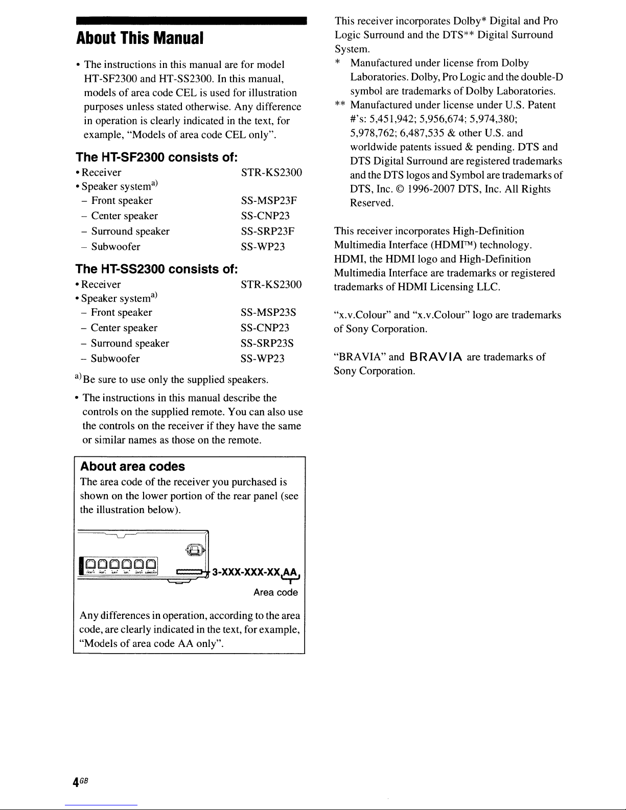
About area codes
The
area codeofthe receiver you purchased is
shown
the illustration below).
~;~-
Anydifferencesinoperation, according to the area
code, are clearly indicated in the text, forexample,
"Modelsofarea code AA only".
on
the lower portionofthe rear panel (see
\:::§9~::::§:9~.
C9
~~P~.J§O_
."~I
~~~
3-XXX-XXX-XX.Af.
Area code
GB
4

Note
RM-AAU022 (Modelsofarea code U, UC, CA
only)
RM-AAU023 (Modelsofarea codeCEL, CEK, AU,
TW,
TH
for
only)
the
supplied
remote
Table
of
Contents
Getting Started
Description and locationofparts 7
1:
Installing the speakers
2:
Connecting the speakers
3:
Connecting the audio/video
components
4:
Connecting the antennas 24
5:
Preparing the receiver and the remote 24
6:
Calibrating the appropriate settings
automatically
(AUTO CALIBRATION) 26
7:
Adjusting the speaker levels and
balance (TEST TONE) 30
14
17
19
Playback
Selecting a component.. 32
ListeninglWatching a component 33
Tu
ner Operations
ListeningtoFM/AM radio 49
Presetting radio stations 50
Using the Radio Data System (RDS) 52
(Models
of
area code CEL, CEK only)
Control for HDMI
Using the Control for HDMI function for
"BRAVIA" Sync 54
Preparing Control for HDMI function 56
Watching a DVD (One-Touch Play) 57
Enjoying the TV sound from the speakers
connected to the receiver
(System Audio Control) 58
Turning off the receiver with the TV
(System Power Off) 59
Amplifier Operations
Navigating through menus
Adjusting the level (LEVEL menu) 39
Adjusting the tone (TONE menu) .40
Settings for the surround sound
(SUR menu) 40
Settings for the tuner (TUNER menu)
Settings for the audio (AUDIO menu)
Settings for the video (VIDEO menu) .42
Settings for the system (SYSTEM menu)
..
35
4l
41
.43
Enjoying Surround Sound
Enjoying Dolby Digital and DTS
Surround sound
(AUTO FORMAT DIRECT) .45
Selecting a pre-programmed sound field .46
Using only the front speakers and
subwoofer (2CH STEREO) .48
Resetting sound fields to the initial
settings 48
Other Operations
Switching between digital and analog audio
(IN MODE) 60
Enjoying the DIGITAL MEDIA PORT
(DMPORT) 60
Using the Sleep Timer 62
Using the Remote
Changing button assignments
63
Additional Information
Glossary 64
Precautions
Troubleshooting 67
Specifications
Index
65
71
75
Getting
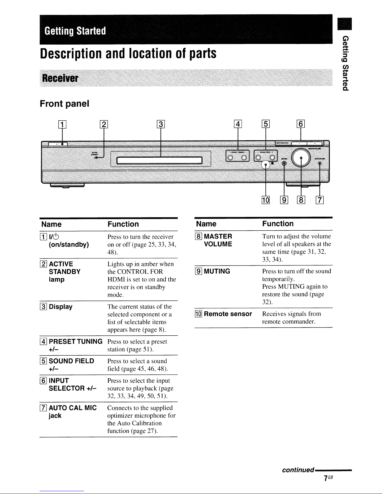
Description
Started
and
Front panel
location
of
parts
c;)
•
C'D
:;
~
c.c
en
Q)
-
"'"
C'D
-
Q.
Name
[I]
I/C)
(on/standby)
[2]
ACTIVE
STANDBY
lamp
~
Display
@]
PRESET TUNING Press to select a preset
+/-
lID
SOUND FIELD
+/-
[§] INPUT
SELECTOR
+/-
Function
Press to turn the receiver
on or
off
(page 25, 33, 34,
48).
Lights up in amber when
the CONTROL FOR
HOMlisset to on and the
receiver
mode.
The current status
selected component or a
list
appears here (page 8).
station (page 51).
Press to select a sound
field (page 45, 46, 48).
Press to select the input
source to playback (page
32,33,34,49,50,51).
is
on standby
of
selectable items
of
the
Name
lID
MASTER
VOLUME
lID
MUTING
[Q]
Remote sensor
Function
Tum
to adjust the volume
of
level
same
33,34).
Presstoturn
temporarily.
Press MUTING again to
restore the sound (page
32).
Receives signals from
remote commander.
all speakers at the
ti
me (page 3 I, 32,
off
the sound
[l]
AUTO CAL MIC
jack
Connects to the supplied
optimizer microphone for
the Auto Calibration
function (page 27).
conffnued---------
GB
7
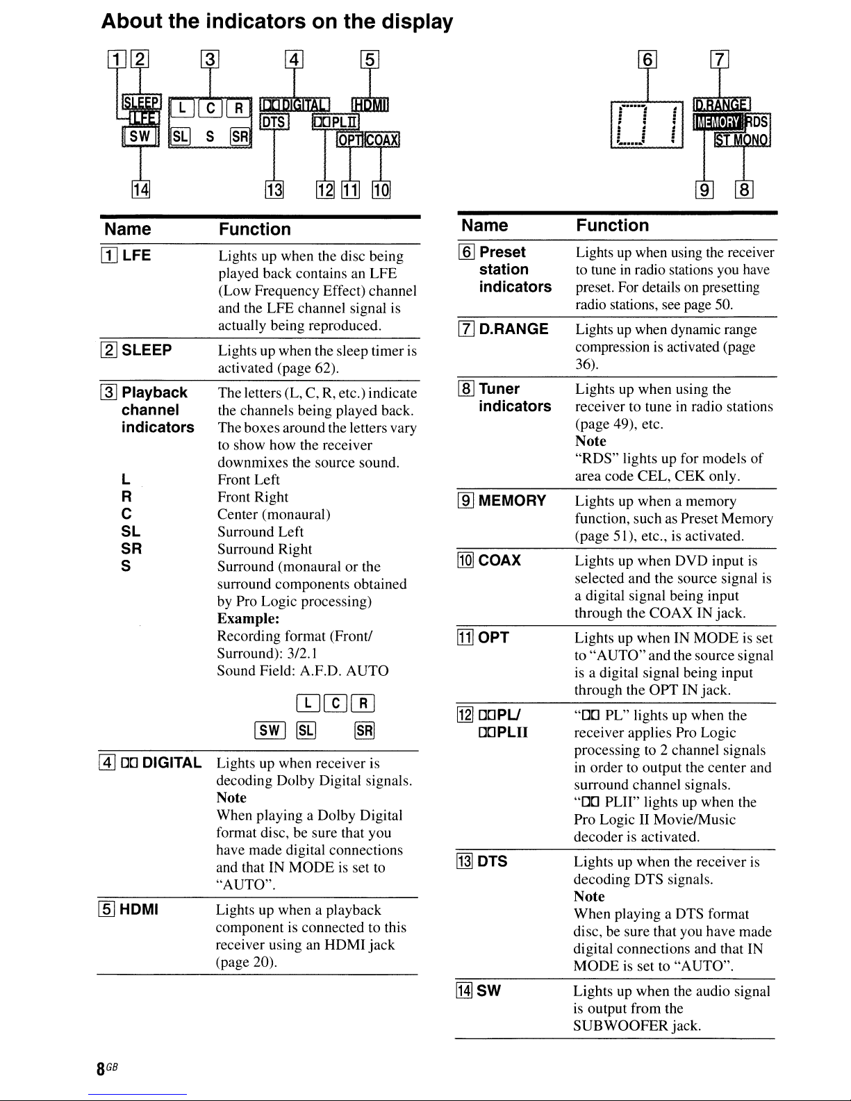
About the indicators on the display
;~
~
~
[]LFE
[g] SLEEP
~
Playback
channel
indicators
L
R
C
SL
SR
S
[[Q
s
FunctionName
Lights up when the disc being
played back contains an
(Low Frequency Effect) channel
and the
actually being reproduced.
Lights up when the sleep timer is
activated (page 62).
The
the channels being played back.
The boxes around the letters vary
to show
downmixes the source sound.
Front
Front Right
Center (monaural)
Surround
Surround Right
Surround (monaural
surround components obtained
by Pro
LFE
channel signal is
letters (L, C, R, etc.) indicate
how
the receiver
Left
Left
Logic
processing)
Example:
Recording format (Front/
Surround): 3/2.1
Sound Field: A.F.D.
LFE
or
the
AUTO
[§]
Preset
station
indicators
[l] D.RANGE
lID
Tuner
indicators
[ill MEMORY
[j]]
COAX
[j]
OPT
FunctionName
Lights up when using the receiver
in
to tune
preset. For details on presetting
radio stations, see page 50.
Lights up when dynamic range
compression is activated (page
36).
Lights up
receiver to tune in radio stations
(page 49), etc.
Note
"RDS"
area code
Lights up when a memory
function, such as Preset Memory
(page 51), etc., is activated.
Lights up when DVD input is
selected and the source signal is
a digital signal being input
through the
Lights up whenINMODE
"AUTO"
to
is a digital signal being input
through the
radio stations you have
when
using the
lights up for models
CEL,
CEK
only.
COAXINjack.
and
the source signal
OPT
IN jack.
of
is set
@]
DO
DIGITAL
Lights up when receiver is
decoding
Dolby
Note
When playing a Dolby Digital
format disc, be sure that you
have made digital connections
and that IN
"AUTO".
ffi] HDMI
GB
8
Lights up when a playback
component is connected to this
receiver using an
(page 20).
Digital signals.
MODE
is set to
HDMI
jack
1121
DOPU
DOPLII
~DTS
[Hjsw
"DO
PL"
lights up when the
receiver applies Pro Logic
processing to 2 channel signals
in
order to output the
surround channel signals.
"DO
PLII" lights up when the
Pro Logic II Movie/Music
decoder
Lights up when the receiver is
decoding
is activated.
DTS
signals.
center
and
Note
When
playing a DTS format
disc, be sure that you have made
digital connections and that IN
MODE
Lights up
is output from the
SUB
is set to
when
WOOFER
"AUTO".
the audio signal
jack.
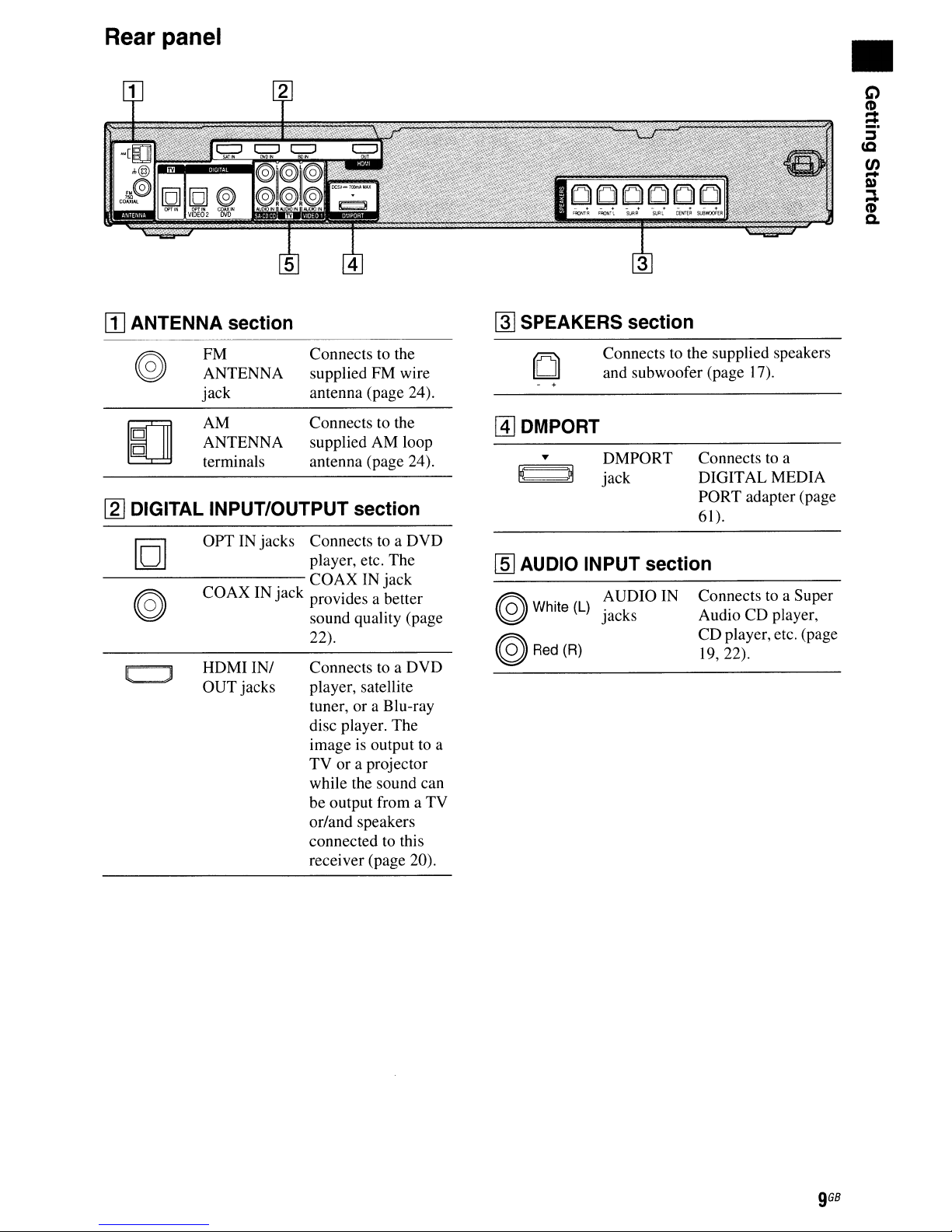
Rear panel
[II
ANTENNA section
~
SPEAKERS section
•
FM
ANTENNA
jack
AM
ANTENNA
terminals
Connects to the
FM
supplied
antenna (page 24).
Connects to the
supplied AM loop
antenna (page 24).
wire
[l] DIGITAL INPUT/OUTPUT section
101
---------.-
OPT IN jacks Connects to a DVD
player, etc. The
COAXINjack
@ COAX IN Jack provides a better
~
HDMIIN/
OUT
jacks
sound quality (page
22).
Connects to a DVD
player, satellite
tuner, or a Blu-ray
disc player. The
is
image
TV or a projector
while the sound can
be output from a TV
or/and speakers
connected to this
receiver (page 20).
output to a
Connects to the supplied speakers
and subwoofer (page 17).
[1]
DMPORT
• DMPORT
E;;;;)l
jack
Connects to a
DIGITAL MEDIA
PORT adapter (page
61).
[ill AUDIO INPUT section
@White(L)
@Red(R)
AUDIO IN
jacks
Connects to a Super
Audio CD player,
CD player, etc. (page
19, 22).

You can use the supplied remote RM-AAU022 (Modelsofarea code U, UC, CA only) or
RM-AAU023 (Models of area code CEL, CEK, AU, TW, TH only) to operate the receiver and
control the Sony audio/video components that the remote is assigned to operate (page 63).
to
RM-AAU022
(Models of area code
CA only)
U,
UC,
RM-AAU023
(Models of area code
TW, TH only)
CEl,
CEK,
AU,
GB
10
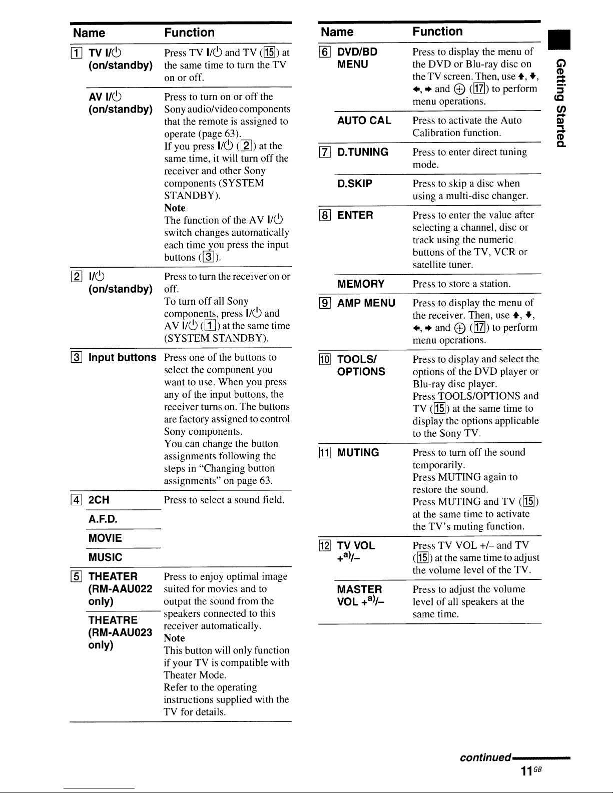
Name Function Name Function
Press
TV
lIe!)
WTV
[g]
~
[1J
[§J
lie!)
(on/standby) the same time to
on or off.
AV
I/e!)
(on/standby) Sony audiolvideocomponents
lie!)
(on/standby) off.
Input buttons
2CH
A.F.D.
MOVIE
MUSIC
THEATER Press to enjoy optimal image
(RM-AAU022 suited for movies and
only) output the sound from the
THEATRE
(RM-AAU023
only)
Press to turn onoroff
that the remoteisassigned to AUTO CAL Press to activate the Auto
operate (page 63). Calibration function.
If
you press
same time, it will turn
receiver and other Sony
components (SYSTEM
STANDBY).
Note
The functionofthe AV
switch changes automatically
each tim1iJou press the input
buttons ( 3
Press to turn the receiveronor
To turn
components, press
AV
lie!)
(SYSTEM STANDBY).
Press oneofthe buttons to
select the component you
want to use. When you press
anyofthe input buttons, the
receiver turns on. The buttons
are factory assigned to control
Sony components.
You can change the button
assignments following the
steps in "Changing button
assignments" on page 63.
Press to select a sound field.
speakers connected to this
receiver automatically.
Note
This button will only function
ifyourTVis compatible with
Theater Mode.
Refer to the operating
instructions supplied with the
TV
for details.
and
lie!)
).
off
all Sony
(W)
at the same time
tum
([g]) at the
TV
lie!)
([1]])
the
the
off
lie!)
and
to
TV
the
at
[ID
DVD/BD
MENU the DVD
Press to display the menu
or
Blu-ray disc on
the TVscreen.Then,
.,
• and e
menu operations.
([IT])
use.,
to perform
of
G)
•
(I)
.,
:::!:
-
::::J
to
en
D)
-
~
(I)
-
[Z]
D.TUNING Press to enter direct tuning
mode.
D.SKIP
[ill
ENTER
MEMORY Press to store a station.
[ID
AMP MENU Press to display the menu
[Q]
TOOLS/ Press to display and select the
OPTIONS options
[j]
MUTING Press to turn
[g]
TV
VOL Press TV VOL
+3)/_
MASTER
VOL +3)/_
Press to skip a disc when
using a multi-disc changer.
Press to enter the value after
selecting a channel, disc
track using the numeric
buttonsofthe TV, VCR or
satellite tuner.
the receiver. Then,
.,
• and e (!IZl) to perform
menu operations.
of
the DVD player
Blu-ray disc player.
Press TOOLSIOPTIONS and
TV
(M!)
at the same time to
display the options applicable
to the Sony TV.
off
the sound
temporarily.
Press MUTING again to
restore the sound.
Press MUTING and TV
at the same time to activate
the
TV's
muting function.
+1-
(M!)
at the same time to adjust
the volume levelofthe TV.
Press to adjust the volume
levelofall speakers at the
same time.
use.,
and
or
of
.,
(M!)
TV
Q.
or
conUnued---------
GB
11
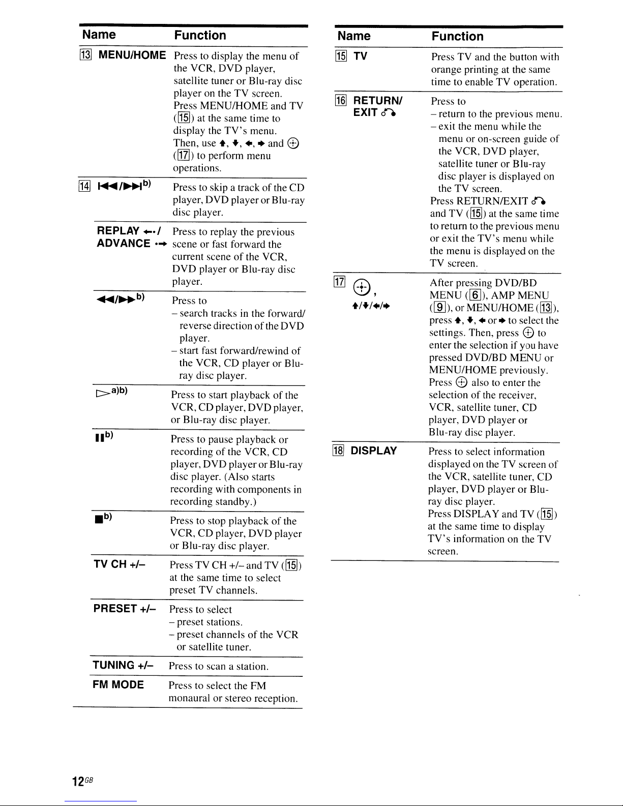
Name Function
~
MENU/HOME Press to display the menu
[HJ
.....
REPLAY..·I
ADVANCE
[:>a)b)
TV CH
/~b)
...
+1-
the VCR,
satellite tunerorBlu-ray disc
player on the
Press
(II§]) at the same time to
display the
Then, use
cirrI>
operations.
Press to skip a trackofthe
player,
disc player.
Press to replay the previous
sceneorfast forward the
current sceneofthe VCR,
DVD
player.
Press to
- search tracks in the forward!
reverse directionofthe
player.
- start fast forward/rewind
the VCR,
ray disc player.
Press to start playbackofthe
VCR, CD player, DVD player,
or
Blu-ray disc player.
Press to pause playback
recordingofthe VCR, CD
player,
disc player. (Also starts
recording with components
recording standby.)
Press to stop playbackofthe
VCR,
or
Blu-ray disc player.
PressTVCH
at the same time to select
preset TV channels.
DVD
TV
MENU/HOME
TV's
+,
+,
to perform menu
DVD
playerorBlu-ray
playerorBlu-ray disc
CD
DVD
playeror Blu-ray
CD
player,
+/-
of
player,
screen.
and TV
menu.
+,
+ and
8)
CD
DVD
of
playerorBlu-
or
in
DVD
player
and
TV
(II§])
Name Function
[1§]
TV
~
RETURNI
EXIT
[1]
0)
+/+/+/+
Ml
DISPLAY
0"
I
Press
TV
orange printing at the same
time to enableTVoperation.
Press to
- return to the previous menu.
- exit the menu while the
menu or on-screen guide
the VCR, DVD player,
satellite tunerorBlu-ray
disc playerisdisplayed on
the
TV
Press RETURNIEXIT
and
TV
to return to the previous menu
or exit the
the menuisdisplayed on the
TV
screen.
After pressing
MENU
dID),
press +,
settings. Then, press8)to
enter the selection if you have
pressed DVD/BD
MENU/HOME
Press8)also to
selectionofthe receiver,
VCR, satellite tuner, CD
player, DVD player
Blu-ray disc player.
Press to select information
displayed on theTVscreen
the VCR, satellite tuner, CD
player, DVD playerorBluray disc player.
Press DISPLAY and
at the same time to display
TV's
screen.
(lID),
or
information on the
and the button with
screen.
0"
([1§])
at the same time
TV's
menu while
DVD/BD
AMP
MENU
MENUIHOME
+,
+
or
+ to select the
MENU
previously.
enter
the
or
TV
of
(~),
or
of
([1§])
TV
PRESET
TUNING
FM MODE Press to select the
GB
12
+1-
+1-
Press to select
- preset stations.
- preset channelsofthe VCR
or
satellite tuner.
Press to scan a station.
monauralorstereo reception.
FM
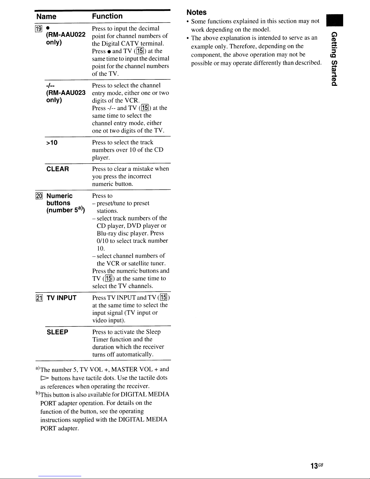
Name
~.
(RM-AAU022
only)
Function
Presstoinput the decimal
point for channel numbers
the Digital CATV terminal.
Press.
same time to inputthe decimal
point for the channel numbers
of
and TV (lI§]) at the
the TV.
of
Notes
• Some functions explained in this section may not
work depending on the model.
• The above explanation
example only. Therefore, depending on the
component, the above operation may not be
possible
or
may operate differently than described.
is
intended to serveasan
•
-1--
(RM-AAU023
only)
>10
CLEAR
!2Q]
Numeric
buttons
(number
to
Press
entry mode, either one or two
digits
Press -/-- and TV
same time
channel entry mode, either
one
Press
numbers over 10
player.
Press to clear a mistake when
you press the incorrect
numeric button.
Press to
- preset/tune to preset
Sa»)
- select track numbers
Oil
- select channel numbers
the VCR or satellite tuner.
Press the numeric buttons and
TV
select theTVchannels.
select the channel
of
the VCR.
to
select the
ot
two digitsofthe TV.
to
select the track
stations.
CD player,
Blu-ray disc player. Press
0 to select track number
10.
(lI§]) at the
DVD
(lI§]) at the
of
the
player or
same
time
of
CD
the
of
to
[gj]
TV
INPUT
SLEEP
a)The number 5, TV VOL +, MASTER VOL + and
C>
buttons have tactile dots. Use the tactile dots
as
references when operating the receiver.
b)This button is also available for DIGITAL MEDIA
PORT adapter operation. For details on the
function
instructions supplied with the DIGITAL MEDIA
PORT adapter.
of
the button, see the operating
Press TV INPUTand TV
at the same time to select the
input signal (TV input
video input).
to
Press
Timer function and the
duration which the receiver
turns
activate the Sleep
off
automatically.
or
(lI§])
13
GB

1:
Installing
the
speakers
This receiver allows you to use a
speaker system. To fully enjoy theater-like
multi channel surround sound, be sure to
connect all the speakers (two front speakers, a
center speaker, and two surround speakers)
and a subwoofer
(5.1
channel).
5.1
channel
HT-SF2300 only
HT-SS2300 only
m Front speaker (left)
rnFront
[!)Center
I!lSurround speaker (left)
filSurround
IiISubwoofer
speaker (right)
speaker
speaker (right)
mFront
rnFront
[!)Center
I!l
filSurround
iii
speaker (left)
speaker (right)
speaker
Surround speaker (left)
speaker (right)
Subwoofer
Tip
Since
the
subwoofer
signals, you
does
can
placeitwherever
not
emit
highly directional
you
want.
GB
14
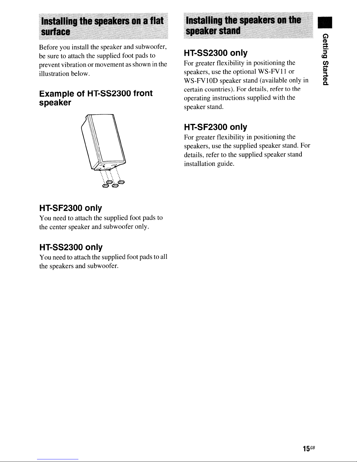
Before you install the speaker and subwoofer,
to
be sure
prevent vibration or movement as shown in the
illustration below.
Exampie of HT-SS2300 front
speaker
attach the supplied foot pads to
HT-SS2300 only
For greater flexibilityinpositioning the
speakers, use the optional
WS-FVlOD speaker stand (available only in
certain countries). For details, refer
operating instructions supplied with the
speaker stand.
HT-SF2300 only
For greater flexibility in positioning the
speakers, use the supplied speaker stand. For
details, refer to the supplied speaker stand
installation guide.
WS-FVll
to
or
the
C)
•
(I)
=
~
cc
fJ)
m
-
.,
(I)
-
a.
HT-SF2300 only
You need to attach the supplied foot pads
the center speaker and subwoofer only.
HT-SS2300 only
You need to attach the supplied foot pads to all
the speakers and subwoofer.
to
15
G8
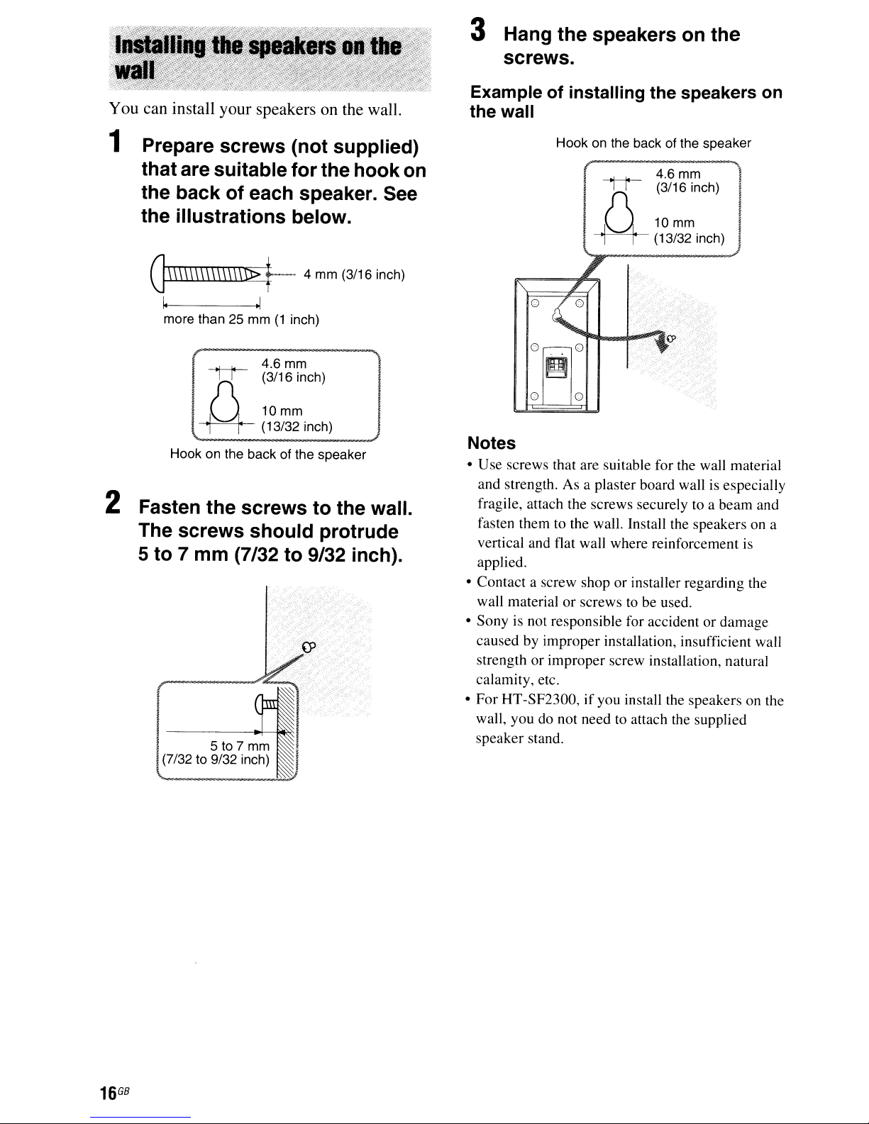
You can install your speakers on the wall.
3 Hang the speakers on the
screws.
Example of installing the speakers on
the wall
1 Prepare screws (not supplied)
thatare suitable for the hook on
the back of each speaker. See
the illustrations below.
G\\\\\\\\\\\\\\D>
~
more than 25 mm(1inch)
}{
U
~
Hook on the back of the speaker
t--
4
~
4.6
mm
(3/16 inch)
10mm
(13/32 inch)
mm
(3/16 inch)
2 Fasten the screws to the wall.
The screws should protrude
5 to 7 mm (7/32 to 9/32 inch).
I 5 to 7
07/32
to 9/32 inch)
mm
Hook on the backofthe speaker
rK
U
~
Q
o 0
Notes
• Use screws that are suitable for the wall material
and strength. As a plaster board wall is especially
fragile, attach the screws securely to a beam and
fasten them to the wall. Install the speakers on a
vertical and flat wall where reinforcement is
applied.
• Contact a screw shop or installer regarding the
or
wall material
• Sony is not responsible for accident or damage
caused by improper installation, insufficient wall
strength or improper screw installation, natural
calamity, etc.
HT
• For
wall, you do not need to attach the supplied
speaker stand.
-SF2300,ifyou install the speakers on the
screws to be used.
~f'~~Ch)
10mm
(13/32 inch)
1,11
G8
16
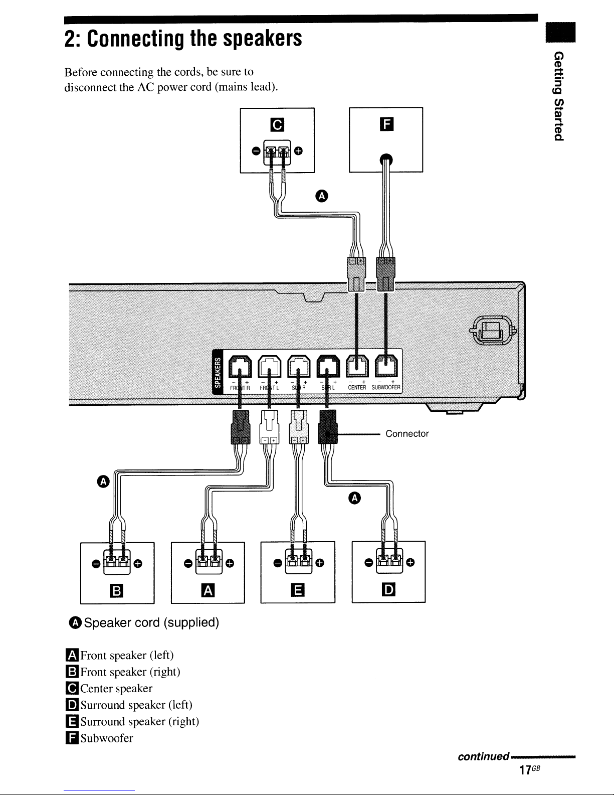
2:
Connecting
Before connecting the cords,besure to
disconnect the AC power cord (mains lead).
the
speakers
•
oSpeaker cord (supplied)
mFront
(ElFront speaker (right)
[!)Center speaker
I!]Surround speaker (left)
(iSurround
IiSubwoofer
speaker (left)
speaker (right)
---
Connector
• 0
Ii]
continued----
17
GB
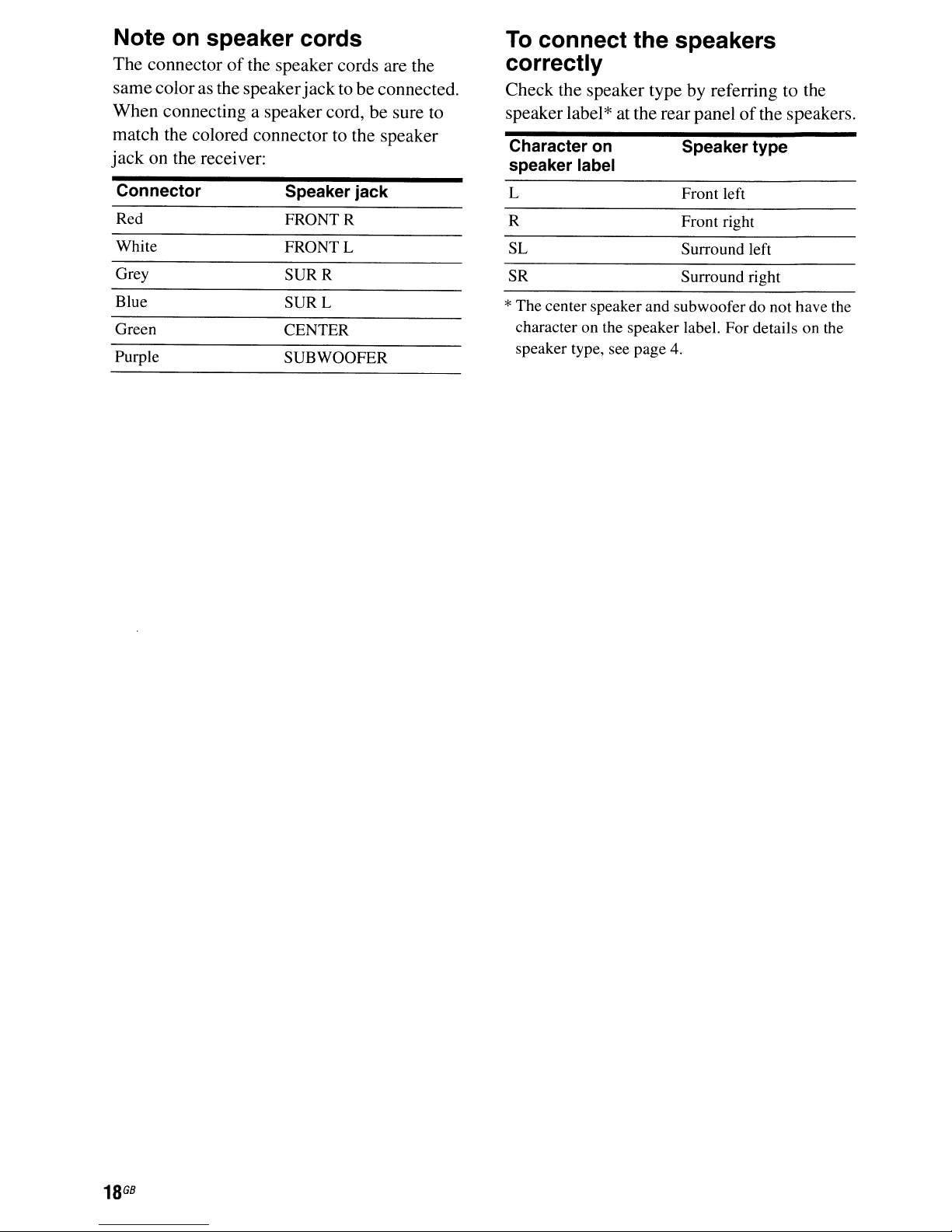
Note on speaker cords
The connectorofthe speaker cords are the
samecoloras the speaker jack to be connected.
When connecting a speaker cord, be sure to
match the colored connector to the speaker
jack
on the receiver:
To
connect the speakers
correctly
Check the speaker typebyreferring to the
speakerlabel
Character
speaker label
on
*at the rear panel
Speaker type
of
the speakers.
Connector
Red
White
Grey
Blue
Green CENTER
Purple SUB WOOFER
Speaker jack
FRONTR
FRONTL
SURR
SURL
L
R
SL
SR
Front left
Front right
Surround left
Surround right
*The center speaker and subwoofer do not have the
character on the speaker label. For details on the
speaker type, see page 4.
GB
18
3:
Connecting
video
components
the
audio/
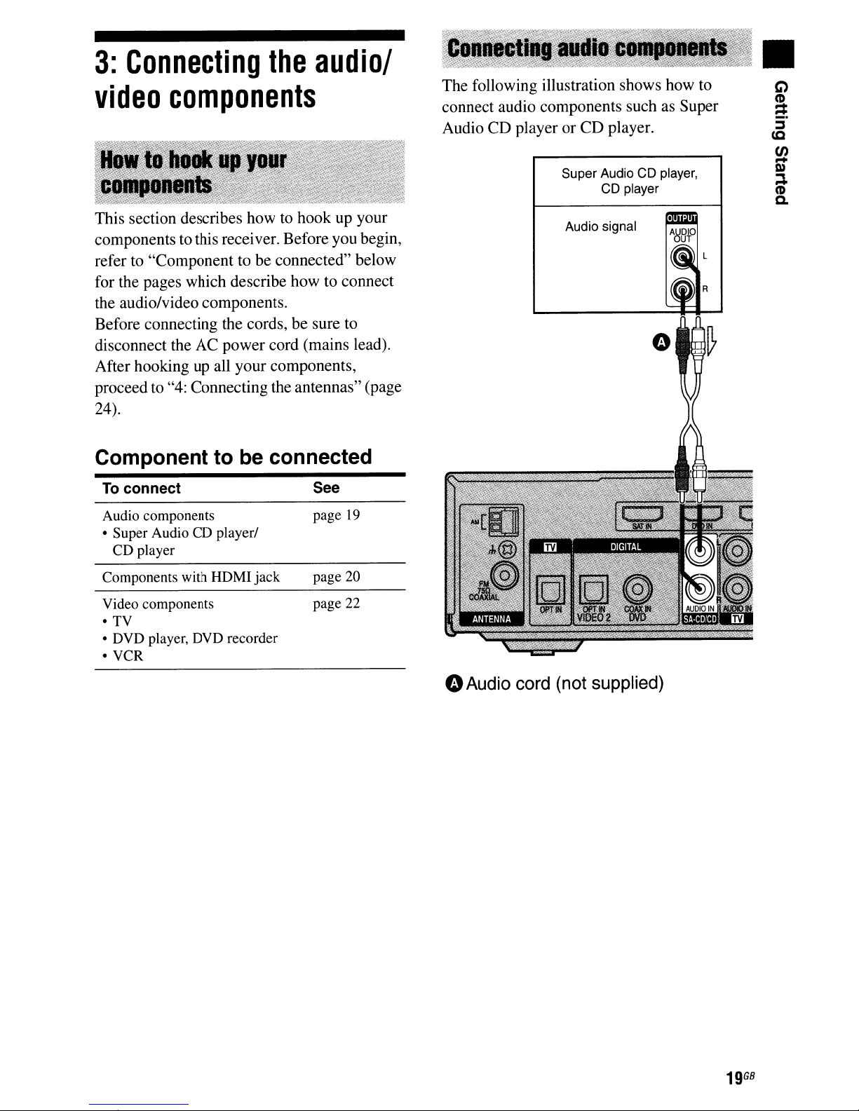
The following illustration shows how to
connect audio components such as Super
Audio CD player
or
CD
player.
Super Audio CD player,
CD player
•
This section describes how to hook up your
components to this receiver. Before you begin,
refer to "Component to be connected" below
for the pages which describe how to connect
the audio/video components.
Before connecting the cords, be sure to
disconnect the AC power cord (mains lead).
After hooking
proceed to "4: Connecting the antennas" (page
24).
up
all your components,
Component to be connected
To
connect
Audio components
• Super Audio CO player/
CD player
Components with HOMI jack
Video components
•
TV
• OVD player, DVD recorder
• VCR
See
page
19
page 20
page 22
Audio signal
GAudio cord (not supplied)
19
GB
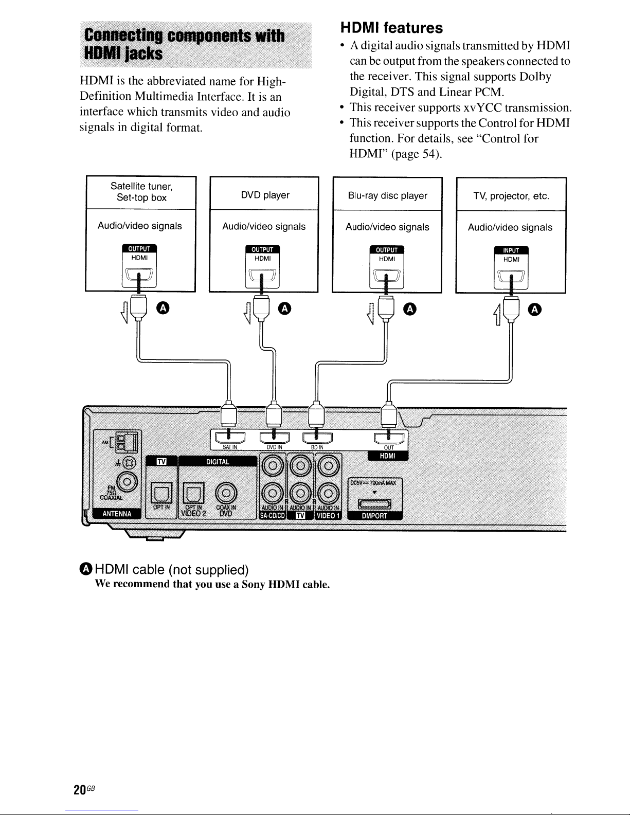
HDMI is the abbreviated name for High-
is
Definition Multimedia Interface. It
interface which transmits video and audio
signals
in
digital format.
an
HOMI features
• A digital audio signals transmitted by HDMI
can be output from the speakers connected to
the receiver. This signal supports Dolby
Digital, DTS and Linear PCM.
• This receiver supports xvYCC transmission.
• This receiver supports the Control for HDMI
function. For details, see "Control for
HDMI" (page 54).
Satellite tuner,
Set-top box
Audio/video signals
..
HOMI
DVD player
Audio/video signals
..
HOMI
Blu-ray disc player
Audio/video signals
..
HOMI
TV,
projector, etc.
Audio/video signals
HOMI
"HDMI
We recommend
GB
20
cable (not supplied)
that
you use a Sony HDMI cable.
Notes on HOMI connections
• An audio signal input to the HDMI IN
is output from the SPEAKERS jacks and
HDMI
other audio jacks.
• Video signals input to the HDMI INjack can
only be output from the HDMI OUT jack.
• When you want to listen to the sound from
the
to
37).
software, set to "AMP". However, the sound
will not output from the
• The multi/stereo area audio signals
Super Audio
• Audio signals (sampling frequency, bit
length, etc.) transmitted from an HDMI
may be suppressed by the connected
component. Check the setup
connectedcomponent
the sound does not come outofa component
connected via the HOMI cable.
• Sound may be interrupted when the
sampling frequency, the number
or the audio format
signals from the playback component
switched.
• When the connected component is not
compatible with copyright protection
technology (HDCP), the image and/or the
sound from the HDMI OUT jack may
distortedormay not be output.
In this case, check the specification
connected component.
• You can enjoy multi channel Linear PCM
only with an HDMI connection.
• Set the image resolution
component to 720p, 1080i or 1080p when
you output 96 kHz multi channel sound over
an HDMI connection.
• You may need to make certain settings
the image resolutionofthe playerbeforeyou
can enjoy multi channel Linear PCM. Refer
to
OUT
jack.Itis
TV
speaker, set "AUDIO FOR HDMI"
"TV+AMP"
If
you cannot play back multi channel
the operating instructionsofthe player.
in the VIDEO menu (page
CD
not output from any
TV
speaker.
are not output.
of
if
the imageispoor
of
the audio output
of
the playback
the
of
jack
of
a
jack
channels
is
be
of
the
on
or
of
• Refer to the operating instructions
component connected for details.
•
We
do not recommend using an HDMI-DVI
conversion cable. When you connect an
HDMI-DVI conversion cable to a DVI-D
component, the sound and/or the image may
not be output.
each
G)
•
C'D
-
-
::::J
cc
en
Q)
-
:::.
C'D
c.
21
GB

The following illustration shows how
connect video components such as DVD
player, DVD recorder, VCR, etc.
Audio signals
to
TV
It
is
not necessary to connect all the cords.
Connect audio and video cords according
the jacksofyour components.
to
Audio signal
DVD player, DVD recorder
o
Optical
e
Audio
e
Coaxial
GB
22
digital
cord
digital
cord
(not
cord
(not
supplied)
(not
Audio signal
VCR
supplied)
supplied)
When you connect a DVD player
or DVD recorder
You can use the DVD input button on the
to
remote
recorder. You may need to change the factory
setting
supplied with this receiver. The factory setting
for the remote
Remote Factory setting
RM-AAU022 DVD player (Change the factory
RM-AAU023 DVD recorder (Change the
control your DVD playerorDVD
of
this button depending on the remote
is
shown in the table below:
settingifyou connect a DVD
recorder)
factory settingifyou connect a
DVD player)
Tips
• To output the soundofthe
connected to the receiver, be sure to
- connect the audio output
TV IN
- turn
muting function.
• All the digital audio
32 kHz, 44.1 kHz, 48 kHz, and 96 kHz sampling
frequencies.
jacksofthe receiver.
off
the
TV's
volumeoractivate the
TV
from the speakers
jacksofthe TV to the
jacks
are compatible with
TV's
•
Tochangethe factory setting
ofthe
DVD input
button on the remote, see "Changing button
assignments" (page 63).
Notes
•Toinput multi channel digital audio from the DVD
player, set the digital audio output settingonthe
DVD player. Refer to the operating instructions
supplied with the DVD player.
• To output sound from the front speakers and the
subwoofer only when you select
sure to:
- connect yourDVDplayer to the
jack
on the receiver.
- press 2CH.
• When connecting optical digital cords, insert the
plugs straightinuntil they click into place.
• Do not bend or tie optical digital cords.
• Be sure to connect the video outputofthe DVD
player, DVD recorder and
the imageisdisplayed on the TV. Refer to the
operating instructionsofeach connected
component for details.
• You cannot do recording on the DVD recorder or
VCR via this receiver. For details, refer to the
operating instructions supplied with the
recorderorVCR.
DVD
DVD
VCR
to the TV, so that
input, be
COAX IN
DVD
23
GB
4:
Connecting
the
5:
Preparing
the
receiver
antennas
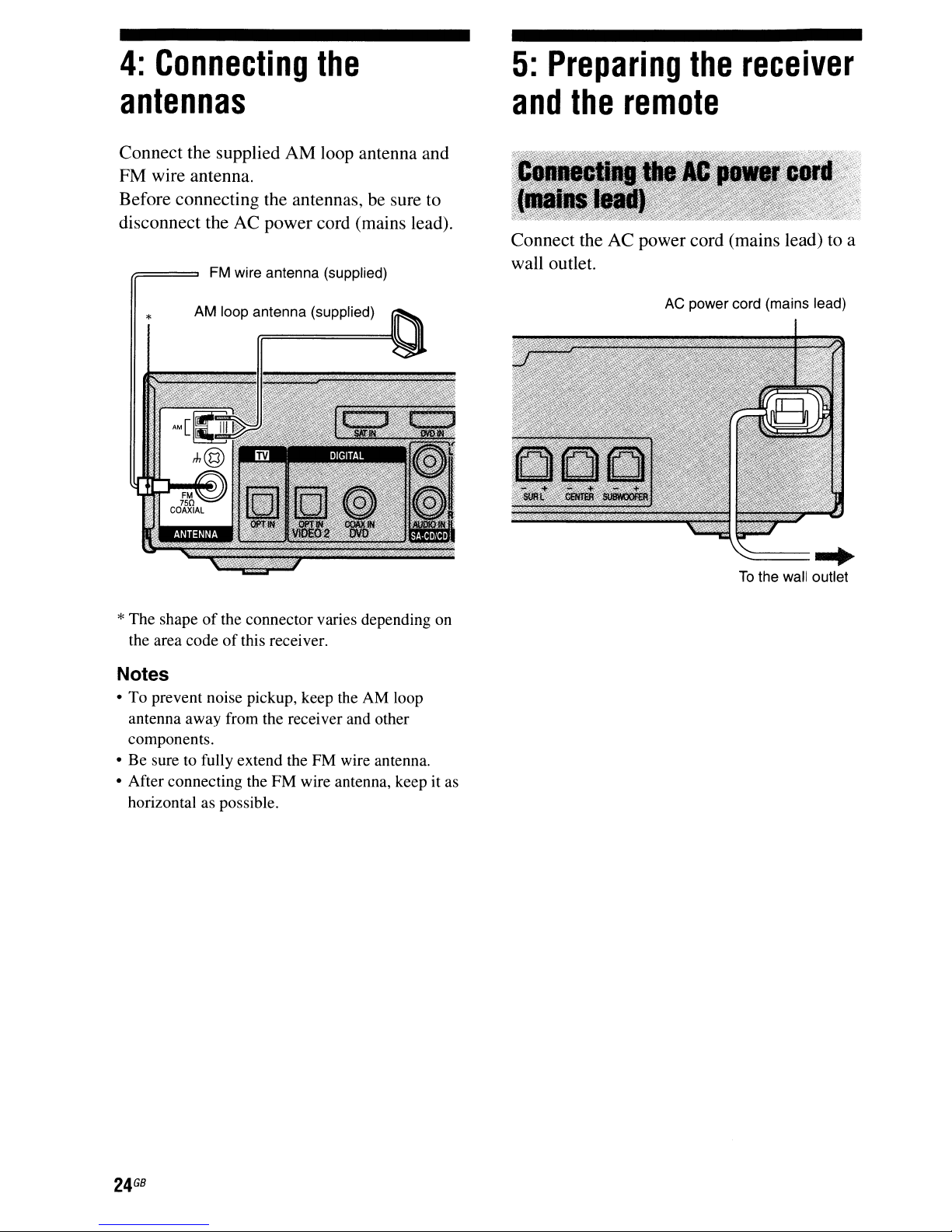
Connect the supplied AM loop antenna and
FM wire antenna.
Before connecting the antennas,
disconnect the AC power cord (mains lead).
FM wire antenna (supplied)
be
sure to
and
Connect the AC power cord (mains lead)toa
wall outlet.
the
remote
AC
power cord (mains lead)
-..:::::::====
To
the wall outlet
.....
*The shape
the area code
Notes
• To prevent noise pickup, keep the AM loop
antenna away from the receiver and other
components.
• Be sure to fully extend the FM wire antenna.
• After connecting the FM wire antenna, keep it as
horizontal as possible.
of
the connector varies depending on
of
this receiver.
GB
24
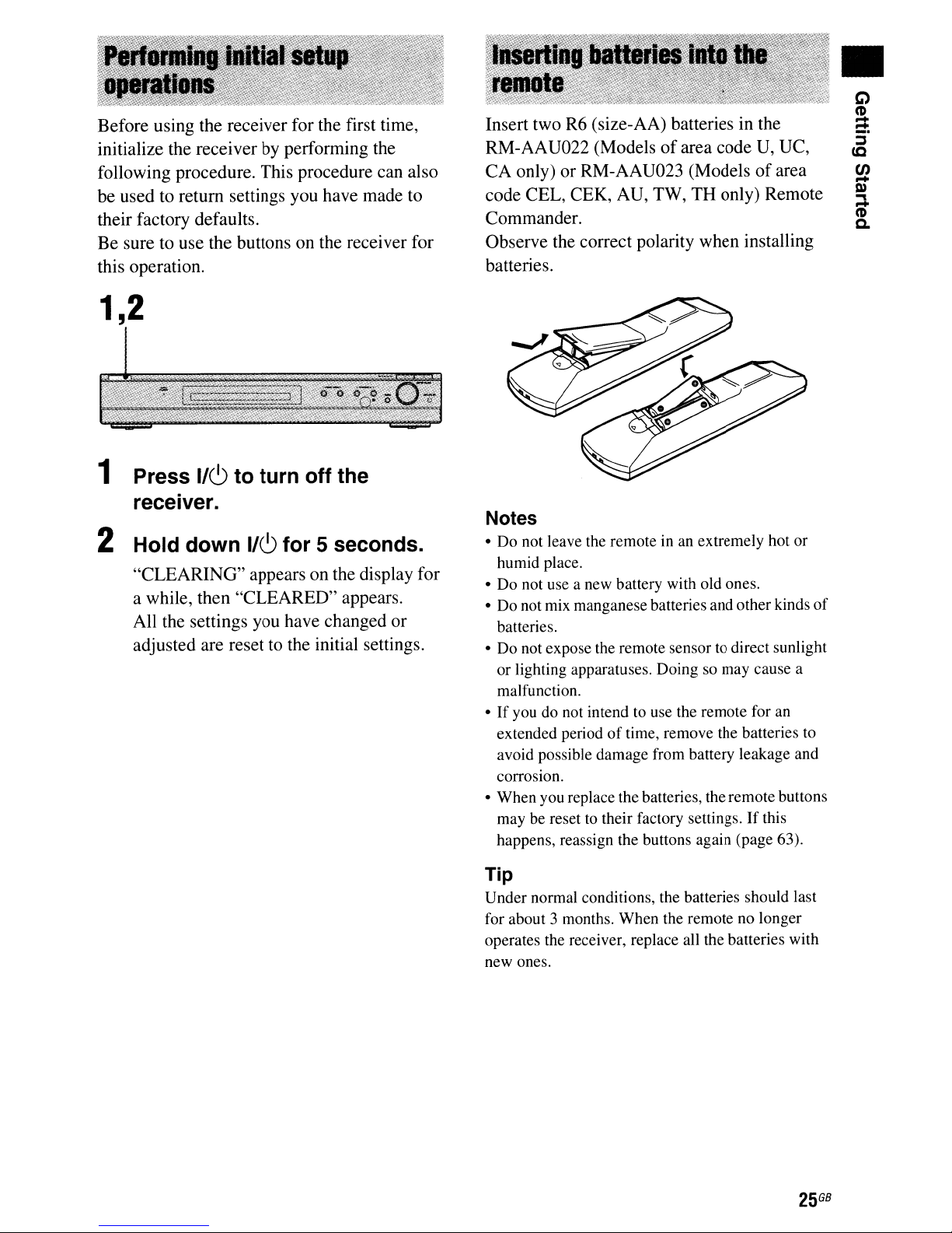
Before using the receiver for the first time,
by
initialize the receiver
following procedure. This procedure can also
be used to return settings you have made to
their factory defaults.
Be sure to use the buttons on the receiver for
this operation.
performing the
1,2
1
Press
receiver.
2 Hold down
"CLEARING" appears on the display for
a while, then "CLEARED" appears.
All the settings you have changed or
adjusted are reset to the initial settings.
lie!)
to turn off the
lie!)
for 5 seconds.
Insert two
RM-AAV022 (Models
CA only) or RM-AAV023 (Modelsofarea
code CEL, CEK,
Commander.
Observe the correct polarity when installing
batteries.
Notes
• Do not leave the remote in an extremely hot or
humid place.
• Do not use a new battery with old ones.
• Do not mix manganese batteries and other kinds
batteries.
• Do not expose the remote sensor to direct sunlight
or lighting apparatuses. Doing so may cause a
malfunction.
•Ifyou do not intend to use the remote for an
extended periodoftime, remove the batteries to
avoid possible damage from battery leakage and
corrosion.
• When you replace the batteries, the remote buttons
may be reset to their factory settings.Ifthis
happens, reassign the buttons again (page 63).
R6
(size-AA) batteries in the
of
area code V, VC,
AV,
TW, TH only) Remote
of
•
Tip
Under normal conditions, the batteries should last
for about 3 months. When the remote no longer
operates the receiver, replace all the batteries with
new ones.
25
GB
 Loading...