

Page 1
FM Stereo
FM-AM Receiver
3-856-160-11(1)
Operating Instructions
Mode d’emploi
EN
F
STR-GA8ES
STR-GA7ES
© 1996 by Sony Corporation
Page 2
- Reorient or relocate the receiving
WARNING
To prevent fire or shock
hazard, do not expose
the unit to rain or
moisture.
antenna.
- Increase the separation between the
equipment and receiver.
- Connect the equipment into an outlet
on a circuit different from that to
which the receiver is connected.
- Consult the dealer or an experienced
radio/TV technician for help.
CAUTION
You are cautioned that any change or
modifications not expressly approved in
this manual could void your authority
to operate this equipment.
Note to CATV system installer
This reminder is provided to call the
This symbol is intended to alert the user
to the presence of uninsulated
“dangerous voltage” within the
product’s
enclosure that may be of sufficient
magnitude to constitute a risk of electric
shock to persons.
CATV system installer’s attention to
Article 820-40 of the NEC that provides
guidelines for proper grounding and, in
particular, specifies that the cable
ground shall be connected to the
grounding system of the building, as
close to the point of cable entry as
practical.
Owner’s record
The model and serial numbers are
This symbol is intended to alert the user
to the presence of important operating
and maintenance (servicing)
instructions in the literature
accompanying the appliance.
IMPORTANT
This equipment has been tested and
found to comply with the limits for a
Class B digital device, pursuant to Part
15 of the FCC Rules.
These limits are designed to provide
reasonable protection against harmful
interference in a residential installation.
This equipment generates, uses, and can
radiate radio frequency energy and, if
not installed and used in accordance
with the instructions, may cause
harmful interference to radio
communications. However, there is no
guarantee that interference will not
occur in a particular installation. If this
equipment does cause harmful
interference to radio or television
reception, which can be determined by
turning the equipment off and on, the
user is encouraged to try to correct the
interference by one or more of the
following measures:
EN
2
located on the rear of the unit. Record
the serial number in the space provided
below. Refer to them whenever you call
upon your Sony dealer regarding this
product.
Model No. STR-GA8ES/STR-GA7ES
Serial No.
For the customers in Canada
CAUTION
TO PREVENT ELECTRIC SHOCK, DO
NOT USE THIS POLARIZED AC PLUG
WITH AN EXTENSION CORD,
RECEPTACLE OR OTHER OUTLET
UNLESS THE BLADES CAN BE FULLY
INSERTED TO PREVENT BLADE
EXPOSURE.
Precautions
On safety
• Should any solid object or liquid fall
into the cabinet, unplug the receiver
and have it checked by qualified
personnel before operating it any
further.
On power sources
• Before operating the receiver, check
that the operating voltage is identical
with your local power supply. The
operating voltage is indicated on the
nameplate at the rear of the receiver.
• This unit is not disconnected from the
AC power source as long as it is
connected to the wall outlet, even if
the unit itself has been turned off.
• If you are not going to use the
receiver for a long time, be sure to
disconnect the receiver from the wall
outlet. To disconnect the AC power
cord, grasp the plug itself; never pull
the cord.
• One blade of the plug is wider than
the other for the purpose of safety
and will fit into the wall outlet only
one way. If you are unable to insert
the plug fully into the outlet, contact
your dealer.
• AC power cord must be changed
only at the qualified service shop.
On placement
• Do not install the appliance in a
confined space, such as a bookcase or
built-in cabinet.
• Place the receiver in a location with
adequate ventilation to prevent heat
buildup and prolong the life of the
receiver.
• Do not place the receiver near heat
sources, or in a place subject to direct
sunlight, excessive dust or
mechanical shock.
• Do not place anything on top of the
cabinet that might block the
ventilation holes and cause
malfunctions.
On operation
• Before connecting other components,
be sure to turn off and unplug the
receiver.
On cleaning
• Clean the cabinet, panel and controls
with a soft cloth slightly moistened
with a mild detergent solution. Do
not use any type of abrasive pad,
scouring powder or solvent such as
alcohol or benzine.
Page 3
For the customers in the USA
For detailed safety precautions, see the
“IMPORTANT SAFEGUARDS” leaflet.
TABLE OF CONTENTS
If you have any question or problem
concerning your receiver, please
consult your nearest Sony dealer.
About This Manual
The instructions in this manual are for
models STR-GA8ES and STR-GA7ES.
Check your model number by looking
at the lower right corner of the front
panel. In this manual, the STR-GA8ES is
the model used for illustration
purposes, any difference in operation is
clearly indicated in the text, for
example, “STR-GA8ES only”.
Conventions
• The instructions in this manual
describe the controls on the receiver.
You can also use the controls on the
remote if they have the same or
similar names as those on the
receiver.
• A “Quick Reference Guide” is
supplied on page 32.
• The “Remote Button Descriptions”
section on page 30 provides an
overview of the remote buttons.
• The following icons are used in this
manual:
Indicates that you can use only
the remote to do the task.
Indicates hints and tips for
making the task easier.
This receiver incorporates the Dolby
Pro Logic Surround system.
Manufactured under license from Dolby
Laboratories Licensing Corporation.
“Dolby ,” the double-D symbol a and
“Pro Logic” are trademarks of Dolby
Laboratories Licensing Corporation.
Getting Started
Unpacking 4
Hookup Overview 4
Antenna Hookups 5
Audio Component Hookups 5
Speaker System Hookups 6
TV/VCR Hookups 8
AC Hookups 9
Before You Use Your Receiver 9
Receiver Operations
Selecting a Component 10
Receiving Broadcasts 11
Presetting Radio Stations 12
Indexing 13
Recording 14
Using the Sleep Timer 15
Using Surround Sound
Introduction 16
Using Pre-programmed Sound Fields 16
Getting the Most Out of Dolby Pro Logic Surround Sound 18
Taking Advantage of the Sound fields 19
Customizing the Sound Fields 20
Advanced Remote Operations
Operating One Component While Using Another
(background operation) 23
Changing the Factory Setting of a FUNCTION Button 23
Programming the Remote 24
Additional Information
Troubleshooting 25
Specifications 26
Glossary 27
Rear Panel Descriptions 29
Remote Button Descriptions 30
EN
F
Index 31
Quick Reference Guide 32
EN
3
Page 4
Getting Started
Unpacking
Check that you received the following items with the
receiver:
• FM wire antenna (1)
• AM loop antenna (1)
• Remote commander (remote) (1)
• Size AA (R6) batteries (2)
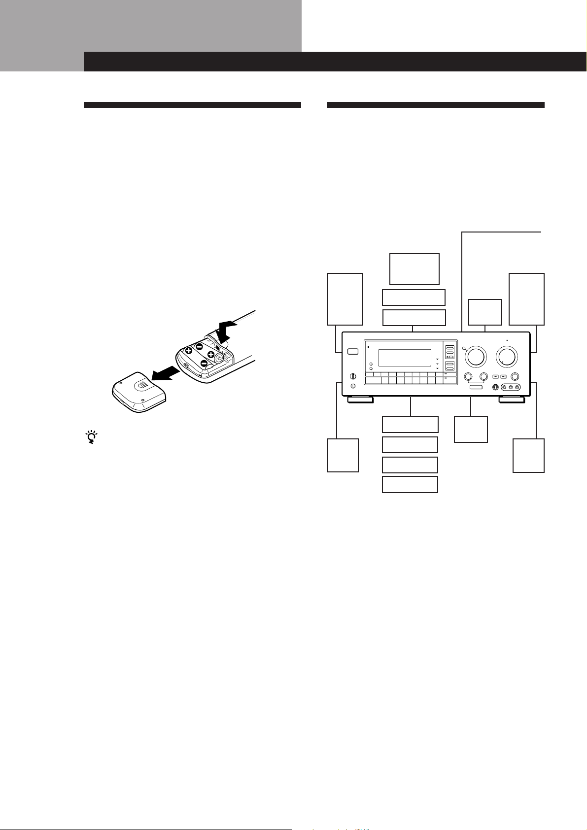
Inserting batteries into the remote
Insert two size AA (R6) batteries with the + and – on
the battery compartment. When using the remote,
point it at the remote sensor g on the receiver.
Hookup Overview
The receiver allows you to connect and control the
following audio/video components. Follow the
hookup procedures for the components that you want
to connect to the receiver on the pages specified. To
learn the locations and names of each jacks, see “Rear
Panel Descriptions” on page 29.
Antenna Hookups (5)
Speaker
System
Hookups (6, 7)
Front
speaker
(L)
TV/VCR Hookups (8, 9)
TV
VCR
LD player
AM/FM antenna
Front
speaker
Active
woofer
(R)
When to replace batteries
Under normal use, the batteries should last for about 6
months. When the remote no longer operates the
receiver, replace both batteries with new ones.
Notes
• Do not leave the remote in an extremely hot or humid
place.
• Do not use a new battery with an old one.
• Do not expose the remote sensor to direct sunlight or
lighting apparatuses. Doing so may cause a malfunction.
• If you don’t use the remote for an extended period of time,
remove the batteries to avoid possible damage from
battery leakage and corrosion.
Center
speaker
Rear
speaker
(R)
Rear
speaker
(L)
CD player
Tape deck
DAT/MD deck
Turntable
Audio Component
Hookups (5, 6)
Before you get started
• Turn off the power to all components before making
any connections.
• Do not connect the AC power cords until all of the
connections are completed.
• Be sure to make connections firmly to avoid hum
and noise.
• When connecting an audio/video cable, be sure to
match the color-coded pins to the appropriate jacks
on the components: Yellow (video) to Yellow; White
(left, audio) to White; and Red (right, audio) to Red.
EN
4
Page 5
Antenna Hookups
Getting Started
Note
To prevent noise pick-up, keep the AM loop antenna away
from the unit and TV set.
Overview
This section describes how to connect AM and FM
antennas to the receiver. If you want to receive radio
broadcasts with the receiver, complete these
connections first, then go to the following pages.
For specific locations of the terminals, see the
illustration below.
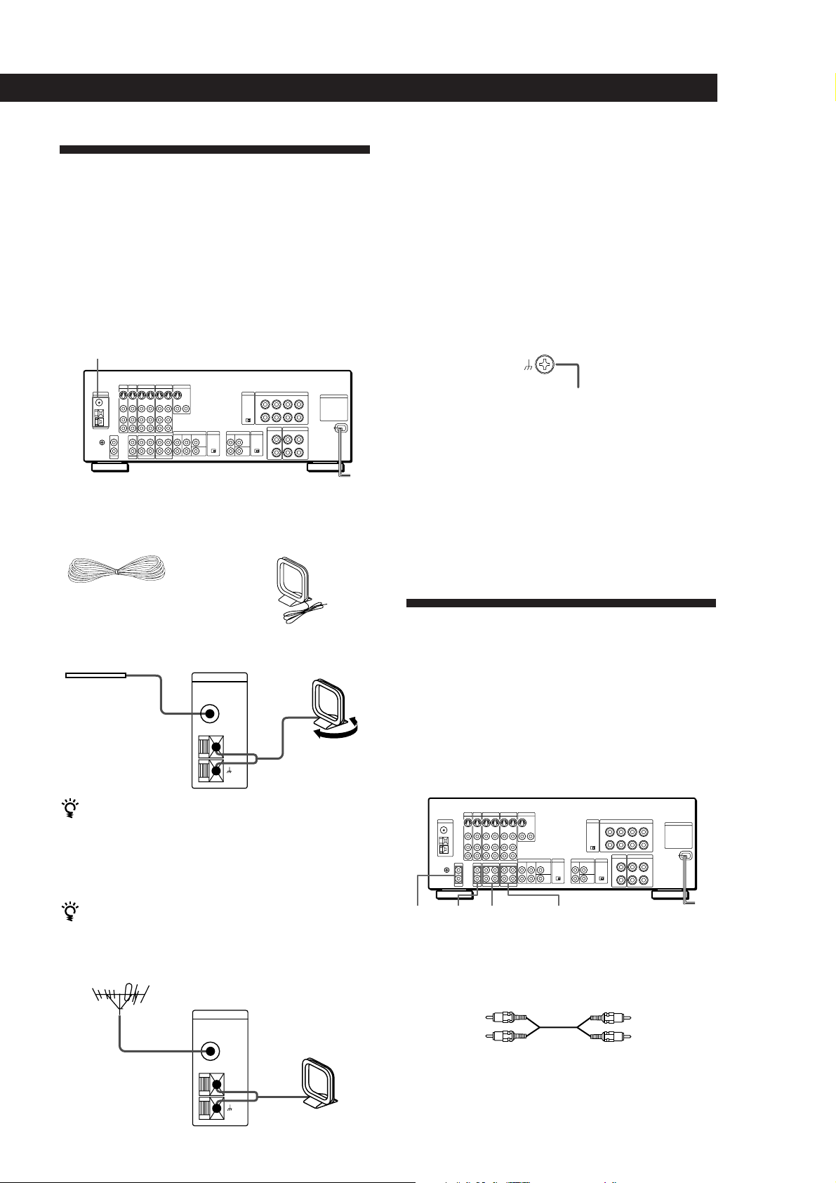
ANTENNA
What antennas will I need?
• FM wire antenna
(supplied) (1)
• AM loop antenna
(supplied) (1)
Hookups
Connecting a ground wire
To prevent hum, connect a ground wire (not supplied)
to the y ground terminal. If you’ve connected an
outdoor antenna, be sure to connect the ground for
lightning protection.
Receiver
.
to ground
Where do I go next?
If you want to connect other components, go on to the next
section. If you’re only planning to use the receiver to listen
to the radio, go to “Speaker System Hookups” on pages 6
and 7.
Audio Component Hookups
FM wire antenna
Receiver
ANTENNA
AM loop antenna
After connecting
the wire antenna,
keep it as horizontal
as possible.
FM
75Ω
COAXIAL
AM
Adjust the
direction.
If AM reception is poor
We reccomed that you purchase and connect the
optional Sony antenna to the unit if reception is
weakened by ferroconcrete used in the construction of
your apartment or buiding.
If you have poor FM reception
Connect a 75-ohm coaxial cable (not supplied) to an FM
outdoor antenna.
FM outdoor antenna
Receiver
ANTENNA
FM
75Ω
COAXIAL
Overview
This section describes how to connect your audio
components to the receiver. If you want to use the
receiver as an amplifier, complete these connections.
For specific locations of the jacks, see the illustration
below.
PHONO CD DAT/MD TAPE
What cords will I need?
Audio cords (not supplied) (1 for each CD player and
turntable; 2 for each tape deck, DAT deck, or MD deck)
White (L)White (L)
Red (R)Red (R)
AM
(continued)
EN
5
Page 6
Getting Started
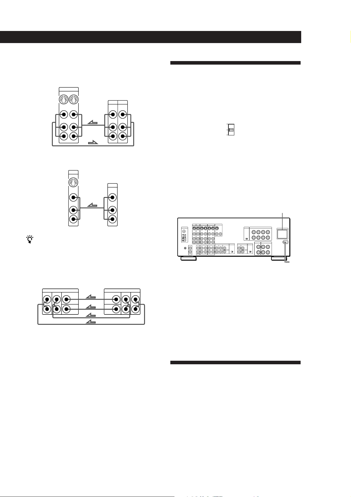
Hookups
The arrow ç indicates signal flow.
CD player
CD player
OUTPUT
LINE
Tape deckReceiver
OUTPUT
DAT/MDReceiver
OUTPUT
Tape deck
DAT/MD
L
R
L
R
Receiver
L
R
IN
CD
INREC OUT
TAPE
INREC OUT
DAT/MD
L
R
INPUT
LINELINE
INPUT
LINELINE
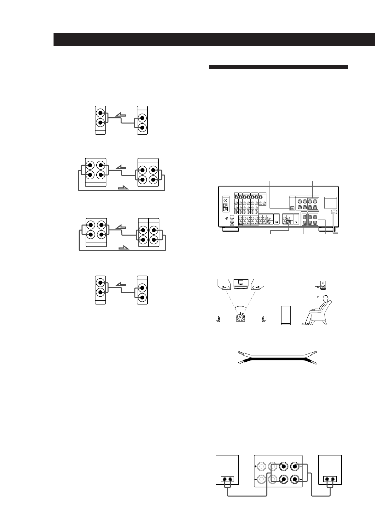
Speaker System Hookups
Overview
This section describes how to connect your speakers to
the receiver. Although front (left and right) speakers
are required, center and rear speakers are optional.
Adding center and rear speakers will enhance the
surround effects. Connecting an active woofer will
increase bass response.
For specific locations of the terminals, see the
L
R
L
R
illustration below.
IMPEDANCE
SELECTOR
WOOFER
FRONT SPEAKERS A
CENTER
SPEAKER
REAR
SPEAKERS
Turntable
Receiver Turntable
L
R
IN
PHONO
OUTPUT
LINE
L
R
• If your turntable has an earth lead
To prevent hum, connect the earth lead to the y ground
terminal on the receiver.
Where do I go next?
Go on to the next section to connect the speakers.
For optimum surround sound effect, place your
speakers as shown below.
Rear speaker
60 - 90 cm
45°
Front speaker
What cords will I need?
Speaker cord (not supplied) (1 for each speaker)
(+)
(–)
(+)
(–)
Twist the stripped ends of the cord about 2/3 inch (15 mm).
Be sure to match the speaker cord to the appropriate
terminal on the components: + to + and – to –. If the cords
are reversed, the sound will be distorted and will lack bass.
Hookups
Front speakers
Front speaker
(R)
Receiver
FRONT SPEAKERS
B
RLARL
Front speaker
(L)
} ]} ]
EN
6
Page 7
Getting Started
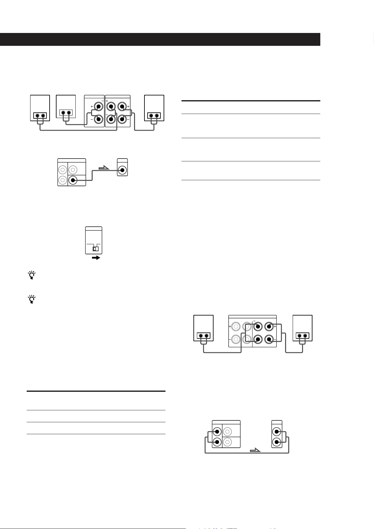
Rear and center speakers
Rear
speaker
(R)
} ]} ]
Center
speaker
} ]
Receiver
CENTER SPEAKER
REAR SPEAKERS
R
L
Rear
speaker
(L)
Active woofer
Receiver
REAR
CENTER
WOOFER
Active woofer
INPUTSURROUND OUT
Note
Set the LOW FILTER switch to ON when you connect an
active woofer. This cuts low frequency output from the front
speakers so you can enjoy pure bass from the active woofer.
LOW FILTER
OFF ON
Selecting the speaker system
If you connect only one set of front speakers, set the
SPEAKERS selector on the front panel to A. If you
connect two sets of front speakers, see the following:
To drive
Speaker system A (connected
to the FRONT SPEAKERS A
terminals)
Speaker system B (connected
to the FRONT SPEAKERS B
terminals)
Both speaker systems A and
B (parallel connection)
* Connect speakers with nominal impedances of 8 ohms, or
higher, to the A and B terminals. You don’t have to switch
the impedance selector, since it switches to 4 ohms
automatically.
Set SPEAKERS selector to
A
B
A+B*
For even more powerful amplification
You can use the POWER SWAP function to connect
two additional amplifiers.
If you have an additional front speaker system
Connect them to the FRONT SPEAKERS B terminals.
If your TV monitor uses separate speakers
You can connect one of them to the SURROUND OUT
CENTER terminal for use with Dolby Pro Logic
Surround Sound (see page 18).
Selecting the impedance
Set the IMPEDANCE SELECTOR for the front speakers
as indicated in the table below. Check the instruction
manual of your speakers if you’re not sure of the
impedance. (This information is usually printed on a
label on the back of the speaker.)
if nominal impedance of
your speaker is
Between 4 and 8 ohms
8 ohms or higher
Set IMPEADANCE SELECTOR to
4 Ω
8 Ω
1 Unplug the power cord.
2 Connect the rear speakers to the FRONT
SPEAKERS terminals on this receiver.
The rear signals are output from the FRONT
SPEAKERS terminals.
Rear speaker
(R)
Receiver
FRONT SPEAKERS
B
RLARL
} ]} ]
Rear speaker
(L)
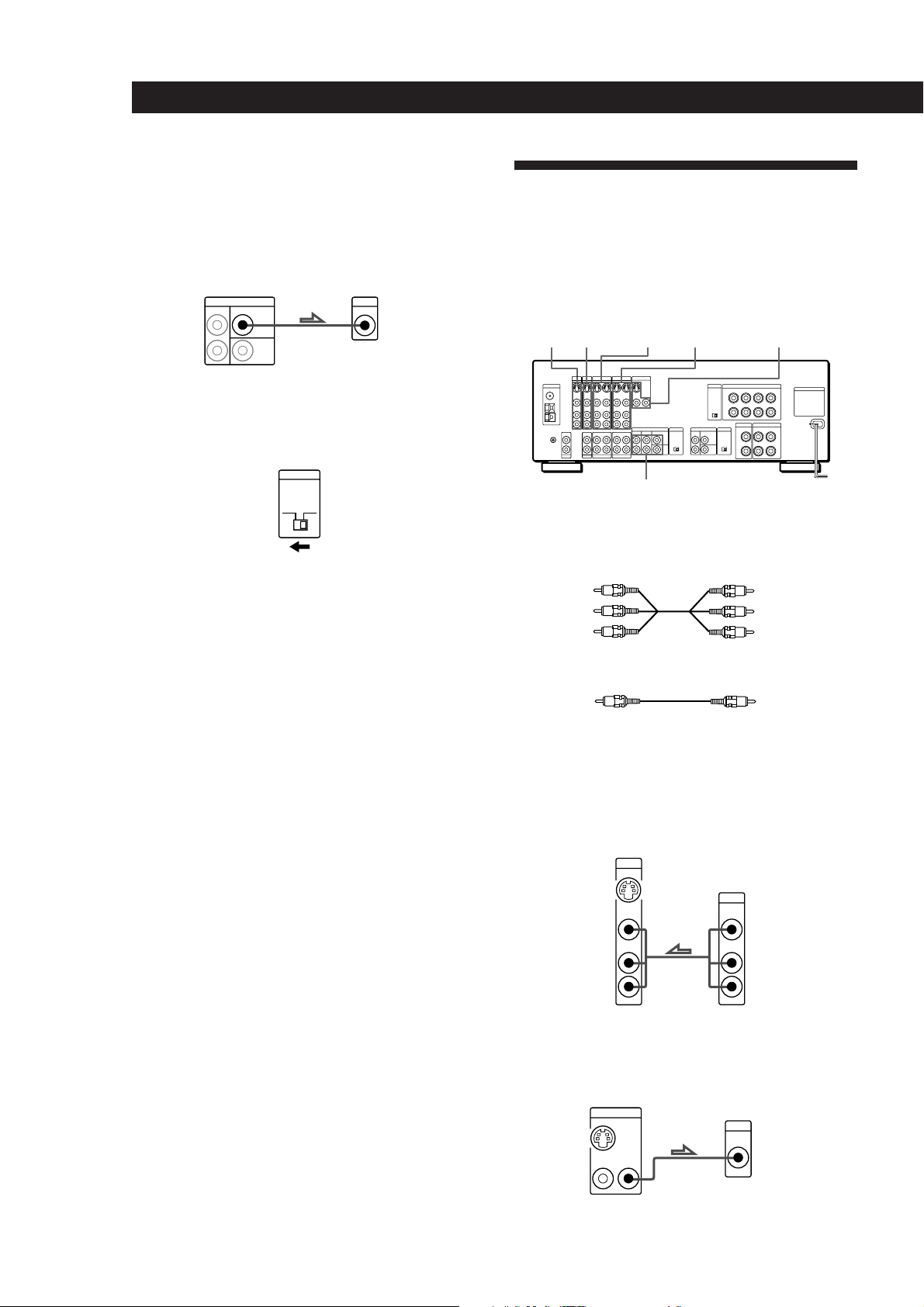
3 Connect the first amplifier to the SURROUND
OUT REAR, and connect the front speakers to this
amplifier.
The front signals are output from the
SURROUND OUT REAR terminals.
Amplifier 1
Receiver
REAR
CENTER
(for front speakers)
INPUTSURROUND OUT
WOOFER
(continued)
EN
7
Page 8
Getting Started
L
R
L
R
TV/DBS
OUTPUT
VIDEO
IN
AUDIO
IN
VIDEO
AUDIO
MONITOR
OUT 1
INPUT
VIDEO
OUT 2
OUT
4 Connect the second amplifier to SURROUND
OUT CENTER, and connect the center speaker to
this amplifier.
The center signal is output from the SURROUND
OUT CENTER terminal.
TV/VCR Hookups
Overview
Amplifier 2
Receiver
REAR
CENTER
WOOFER
(for center speaker)
INPUTSURROUND OUT
5 Remove the cover on the POWER SWAP selector
and set the selector to the SWAP position.
After you have completed the setting, reattach the
cover to the selector and plug in the power cord.
POWER SWAP
SWAP NORMAL
To adjust the volume
Set the volume control of the separate amplifiers to the
maximum position and adjust the volume level with the
volume control of the receiver.
Notes
• For best results, we recommend using a pair of equivalent
amplifiers to boost front and center speaker output. You
can, however, connect the center speakers to the CENTER
SPEAKER terminals if you only have one additional
amplifier.
• Do not use the terminals labeled CENTER SPEAKER or
REAR SPEAKERS if you connect two additional
amplifiers. Make connections as shown above.
• If you want to turn off the power swap function, set the
POWER SWAP selector to the NORMAL position.
This section describes how to connect video
components to the receiver. For specific locations of the
jacks, see the illustration below.
TV/DBS
VIDEO 2 VIDEO 1LD MONITOR
5.1 INPUT
What cables will I need?
• Audio/video cable (not supplied) (1 for each TV or LD
player; 2 for each VCR)
Yellow
White (L)
Red (R)
Yellow
White (L)
Red (R)
• Video cable (not supplied) (1 for a TV monitor)
Yellow
Yellow
Hookups
The arrow ç indicates signal flow.
TV tuner or DBS (Digital Broadcasting Satellites) receiver
Receiver
TV/DBS
Where do I go next?
To complete your system, go to “AC Hookups” on page 9. If
you want to connect video components to enjoy surround
sound when watching TV programs or video tapes, go on to
the next section.
Monitor
If you are using your TV as a monitor, do not connect
anything to the TV IN jacks.
Receiver
EN
8
Monitor
Page 9
VCR (via the VIDEO 1 jacks)
If you have two VCRs connect the second one to the VIDEO
2 jacks.
Receiver
VIDEO 1
INOUT
VIDEO
VIDEO
IN
OUT
AUDIO
AUDIO
IN
OUT
L
R
VCR
OUTPUT
VIDEO VIDEO
AUDIO AUDIO
INPUT
L
R
Getting Started
AC Hookups
If your receiver has a voltage selector on the rear panel
Your receiver operates on either 120, 220 or 240 V AC. Before
connecting the unit to a wall outlet, be sure to set the voltage
selector on the rear of the unit to the appropriate position
according to your local power supply.
220V
240V
120V
x
Connecting the AC power cord
LD player
Receiver
LD
IN
VIDEO
IN
AUDIO
IN
L
R
LD
OUTPUT
VIDEO
AUDIO
L
R
You can play decoded AC-3 soundtracks through the
speakers connected to the receiver.
If you have an AC-3 decoder you can use the receiver to
listen to decoded AC-3 soundtrack with the following
connections (see page 10 for details regarding
operation).
Receiver
FRONT
5.1 INPUT
REAR
CENTER
WOOFER
AC-3 decoder
(etc.)
PRE OUT
CENTER
WOOFER
REAR FRONT
Connect the AC power cord from this receiver and
from your audio/video components to a wall outlet.
If you connect other audio components to the
SWITCHED AC OUTLET(s) on the receiver, the
receiver can supply power to the connected
components so you can turn on/off whole system
when you turn on/off the receiver.
SWITCHED AC OUTLET(s)
/
to a wall
Caution
outlet
Make sure that the power consumption of the component(s)
connected to the receiver’s AC outlet(s) does not exceed the
wattage indicated on the rear panel. Do not connect highwattage electrical home appliances such as electric irons,
fans, or TVs to this outlet.
Where do I go next?
Where do I go next?
Go on to the next section to connect an AC plug and
complete your home theater system.
Before you use the␣ receiver, go to the next section to make
sure that all the controls are set to the appropriate positions.
Before You Use Your Receiver
Before you start using your receiver, make sure that
you have:
• Turned MASTER VOL to the leftmost position (0).
• Selected the appropriate speaker system. (For
details, see “Selecting the speaker system” on
page 7.)
• Set BALANCE to the center position.
Turn on the receiver and check the following indicator.
• Press MUTING on the remote if the MUTING
indicator turns on.
EN
9
Page 10
Receiver Operations
Receiver Operations
Selecting a Component
To listen to or watch a connected component, first
select the function on the receiver or with the remote.
Before you begin, make sure you have:
• Connected all components securely and correctly as
indicated on pages 5 to 9.
• Turned MASTER VOL to the leftmost position (0) to
avoid damaging your speakers.
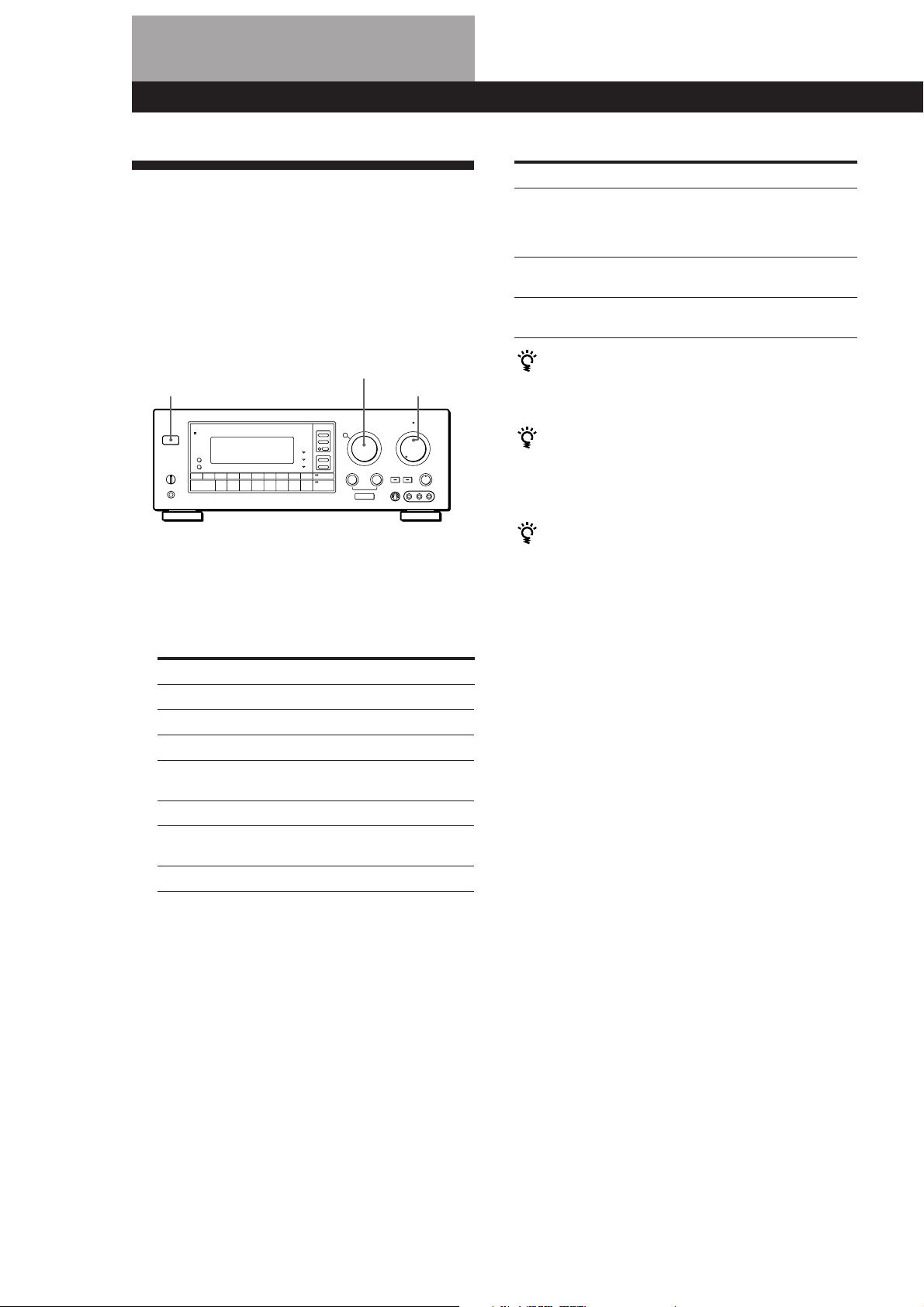
FUNCTION
POWER
1 Press POWER to turn on the receiver.
2 Turn FUNCTION to select the component you
want to use:
To listen to or watch Select
Records PHONO
Radio programs TUNER
Compact Discs (CD) CD
Digital Audio Tapes (DAT) DAT/MD
or MiniDiscs (MD)
TV programs or DBS TV/DBS
Video tapes VIDEO 1, VIDEO 2
Laser discs LD
To listen to analog audio cassettes
Press TAPE MONITOR, the button’s indicator lights up
and “TAPE” appears in the display.
To listen to decoded AC-3 program sources
Select a video source (TV, LD, VIDEO 1, VIDEO 2, or
VIDEO 3) then press 5.1 INPUT, the indicator on the
button lights up. The receiver memorizes 5.1 INPUT
on/off setting independently for each source.
MASTER VOL
or VIDEO 3
To Do This
Mute the sound Press MUTING on the remote.
The MUTING indicator on the
front panel lights up.
Press again to restore the sound.
Reinforce the bass Press BASS BOOST to turn on
the BASS BOOST indicator
Adjust the balance Turn the BALANCE control to
the left (L) or right (R).
When you listen with headphones
Connect the headphones to the PHONES jack and set
the SPEAKERS selector to OFF.
When you want to enjoy high quality sound
Press DIRECT PASS to bypass the tone controls, bass
reinforcement, and surround effects.
The indicator on the button lights up.
When you want to adjust the brightness of the
display
Press DIMMER repeatedly to select the brightness you
desire.
Watching video programs
When you watch TV or video programs, we
recommend you play audio portion through the
receiver instead of your TV’s speaker. This lets you
take advantage of the receiver’s surround sound
effects, like Dolby Surround, and lets you use the
receiver’s remote to control the audio.
Turn off the speakers on your TV before you start so
you can enjoy the surround sound from your receiver.
To watch TV programs, turn on both the TV and the
receiver and turn FUNCTION to select TV.
To watch videos or laser discs, do the following:
1 Turn FUNCTION to select the component (for
example, VIDEO 1).
2 Turn on the TV and set the TV’s video input to
the receiver.
3 Turn on the component (VCR or LD player), and
start playback.
10
3 Turn on the component, for example, a CD player,
and then start playing.
To tune in radio stations on this receiver, see
“Receiving Broadcasts” on page 11.
4 Turn MASTER VOL to adjust the volume.
To adjust the volume of the TV's speakers, use the
volume control on the TV.
EN
Page 11
Receiver Operations
Using the remote
The remote lets you operate the receiver and the
connected Sony components that can be controlled
with the remote commander.
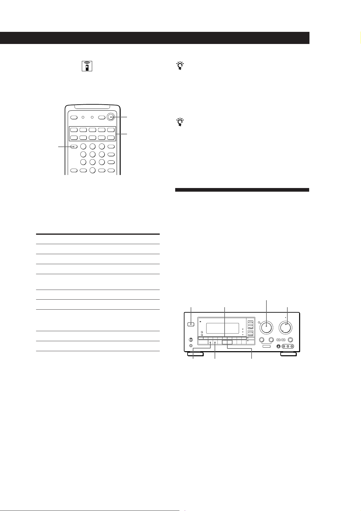
SYSTEM OFF
SYSTEM
CONTROL/
TV CONTROL
ON
(Press to set remote
to operate TV only)
FUNCTION
1 Press one of the SYSTEM CONTROL/
FUNCTION buttons to select the component you
want to use.
The receiver and the selected component turn on.
The SYSTEM CONTROL/FUNCTION buttons on
the remote are factory-set as follows:
To listen to or watch Press
Records PHONO
Radio programs TUNER
Compact Discs (CD) CD
Digital Audio Tapes (DAT) DAT/MD
or MiniDiscs (MD)
Audio tapes TAPE
TV programs TV
Video tapes VIDEO 1 (VTR 3*)
Laser discs LD
Decoded AC-3 programs 5.1 INPUT
VIDEO 2 (VTR 1*)
VIDEO 3 (VTR 2*)
If you use a Sony TV
When you press TV to watch a TV program, the TV
turns on and switches to the TV input. The TV also
turns on automatically and switches to the appropriate
video input when you press VIDEO 1, VIDEO 2. If the
TV does not switch to the appropriate input
automatically, press TV/VIDEO on the remote.
Watching TV without the receiver (for Sony TVs only)
Press TV CONTROL ON to set the remote to operate TV
functions only (see “Remote Button Descriptions” on
page 30 for details). When you press this button, the TV
turns on and switches to the TV input. If the TV does
not automatically switch to the TV input, press TV/
VIDEO.
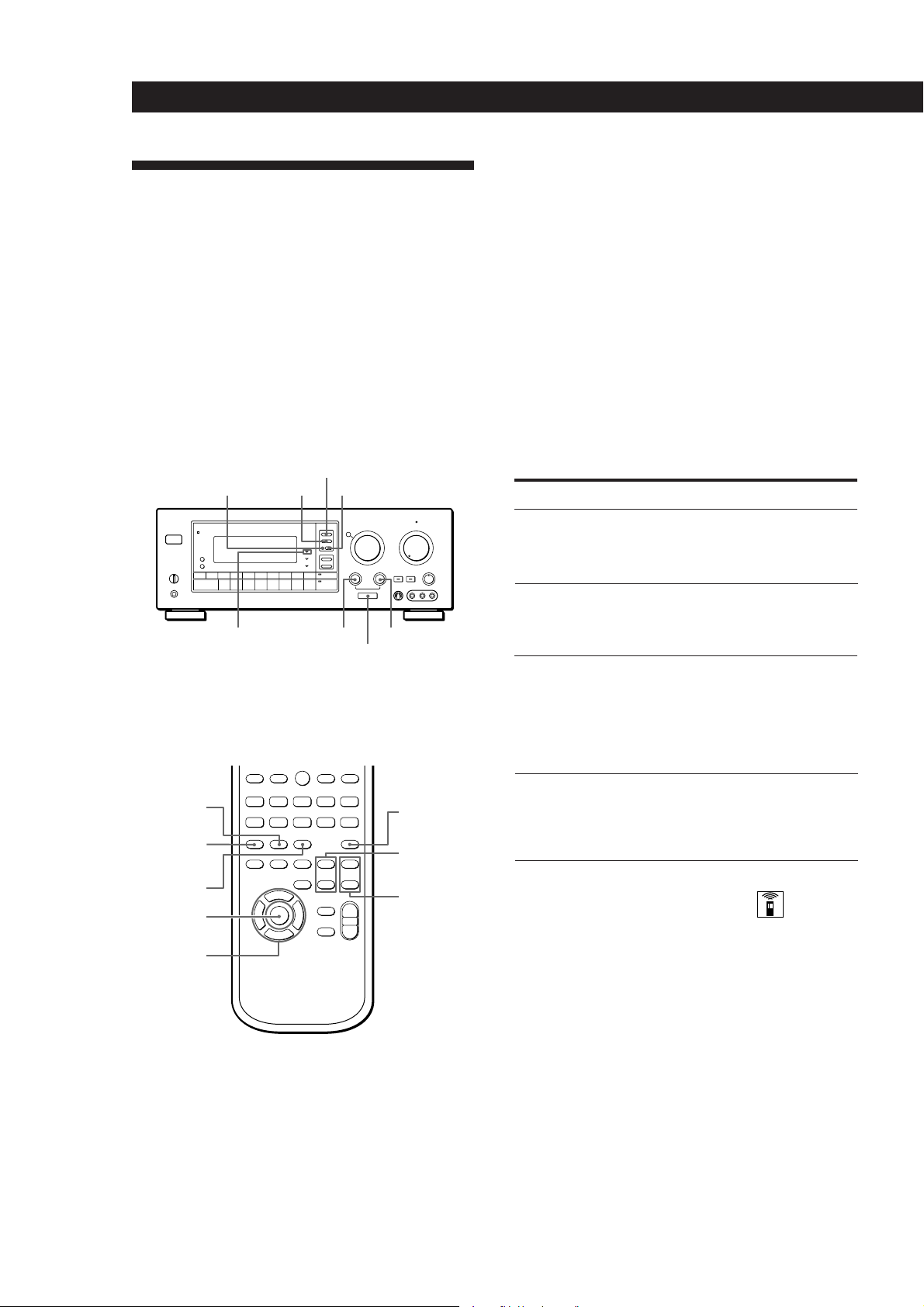
Receiving Broadcasts
This receiver lets you enter a station’s frequency
directly by using the numeric buttons (direct tuning). If
you don’t know the frequency of the station you want,
see “Receiving broadcasts by scanning stations”
(automatic tuning).
Before you begin, make sure you have:
• Connected an FM/AM antenna to the receiver as
indicated on page 5.
• Selected the appropriate speaker system. (For details,
see “Selecting the speaker system” on page 7.)
FUNCTION
POWER
Number buttons
MASTER VOL
* Sony VCRs are operated with a VTR 1, 2, or 3 setting
that correspond to Beta, 8mm, and VHS respectively.
If you want to change the factory setting of a button
See page 23.
If the component does not turn on
Press the power switch on the component.
2 Start playing.
Refer to “Remote Button Descriptions” on page 30
for details.
To turn off the components
Press SYSTEM OFF. This will also turn off the video and
audio components connected to the SWITCHED AC
OUTLETs on the back of this unit at the same time.
FM/AM
DIRECT
TUNING
INDEX
– / +
1 Press POWER to turn on the receiver.
2 Turn FUNCTION to select “TUNER”.
The last received station is tuned in.
3 Press FM/AM to select FM or AM stations.
4 Press DIRECT TUNING.
(continued)
11
EN
Page 12
Receiver Operations
5 Press the numeric buttons to enter the frequency.
Example 1:FM 102.50 MHz Example 2:AM 1350kHz
1 0250
(You don’t have to enter
the last “0.”)
1 35
6 When you tune in AM stations, adjust the
direction of the AM loop antenna for optimum
reception.
To receive other stations
Repeat Steps 3, 4 and 5.
If the STEREO indicator remains off
Press FM MODE even when an FM stereo broadcast is
received.
If an FM stereo program is distorted
The STEREO indicator flashes. Press FM MODE to
change to monaural (MONO). You will not have the
stereo effect but the distortion will be reduced. To
return to the auto stereo mode, press this button again.
If you cannot tune in a station and the entered
numbers are flashing
Make sure you’ve entered the right frequency. If not,
reenter the frequency you want.
If the entered numbers still flash, the frequency is not
used in your area.
Press INDEX + or –.
4
Press the + button for a higher station number;
press the – button for a lower one. When you tune
past either end of the band, the receiver
automatically jumps to the opposite end and
continues scanning in the same direction. Every
time a station is received, the receiver stops
scanning. To continue scanning, press the button
again.
Presetting Radio Stations
You’ll most likely want to preset the receiver with the
radio stations you listen to often so that you don’t have
to tune in the station every time. The receiver can store
a total of 30 FM or AM stations. You can store the
stations on preset numbers combining 3 characters (A,
B and C) and numbers (0-9). For example, you can
store a station as preset number A1, B6, or C9.
Numeric buttons
FUNCTION
12
EN
To watch FM simulcast TV programs
Make sure that you tune in the simulcast program on
both the TV (or VCR) and the receiver.
If you enter a frequency not covered by the tuning
interval
The entered value is automatically rounded up or down
to the closest covered value.
Tuning intervals for direct tuning are:
FM: 50 kHz intervals
AM: 10 kHz intervals (to change to 9 kHz intervals, see
page 27)
Receiving broadcasts by scanning stations
(automatic tuning)
If you don’t know the frequency of the radio station
you want, you can have the receiver scan all the
receivable stations to locate the one you want.
1 Select TUNER.
The last received station is tuned in.
2 Press DISPLAY so that the frequency appears in
the display.
3 Press FM/AM to select FM or AM.
SHIFT
– / +
MEMORYPRESET
1 Turn FUNCTION to select “TUNER”.
The last received station is tuned in.
2 Tune in the station you want.
If you are not familiar with how to tune in a
station, see “Receiving Broadcasts” on the
previous page.
3 Press MEMORY.
“MEMORY” appears for a few seconds.
Do steps 4 and 5 before “MEMORY” goes out.
4 Press SHIFT to select a memory page (A, B or C).
Each time you press SHIFT, the letter “A”, “B” or
“C” appear in the display.
5 Press the number you want to use (0 to 9).
If “MEMORY” goes out before you specify the preset
number, start again from step 3.
6 Repeat steps 2 to 5 to preset other stations.
To change a preset station
Preset a new station on the number you want to change.
Page 13
Receiver Operations
Note
If the AC power cord is disconnected for about one week,
the preset stations will be cleared from the receiver’s
memory, and you will have to preset the stations again.
Tuning preset stations (preset tuning)
You can tune directly to a preset station by entering its
preset number. If you don’t know which stations are
preset on which numbers, you can tune by scanning
the preset stations.
1 Select TUNER.
The last received station is tuned in.
2 Press SHIFT to select a memory page (A, B or C),
then press the number.
For example, select A and then press 7 to tune in
the station preset as A7.
You can also tune by scanning the preset stations
Press TUNER and then DISPLAY so that the frequency
display appears. Then press PRESET + or – to select the
station you want. Each time you press the buttons, the
preset numbers change as follows:
nA1˜A2˜...A9˜A0˜B1˜B2˜...B9˜B0N
nC0˜C9...C2˜C1N
STR-GA7ES
INDEX
+ / –
PRESET
+ / –
MEMORY
CHARACTER
DISPLAY
DPC
MODE
FUNCTION
POSITION
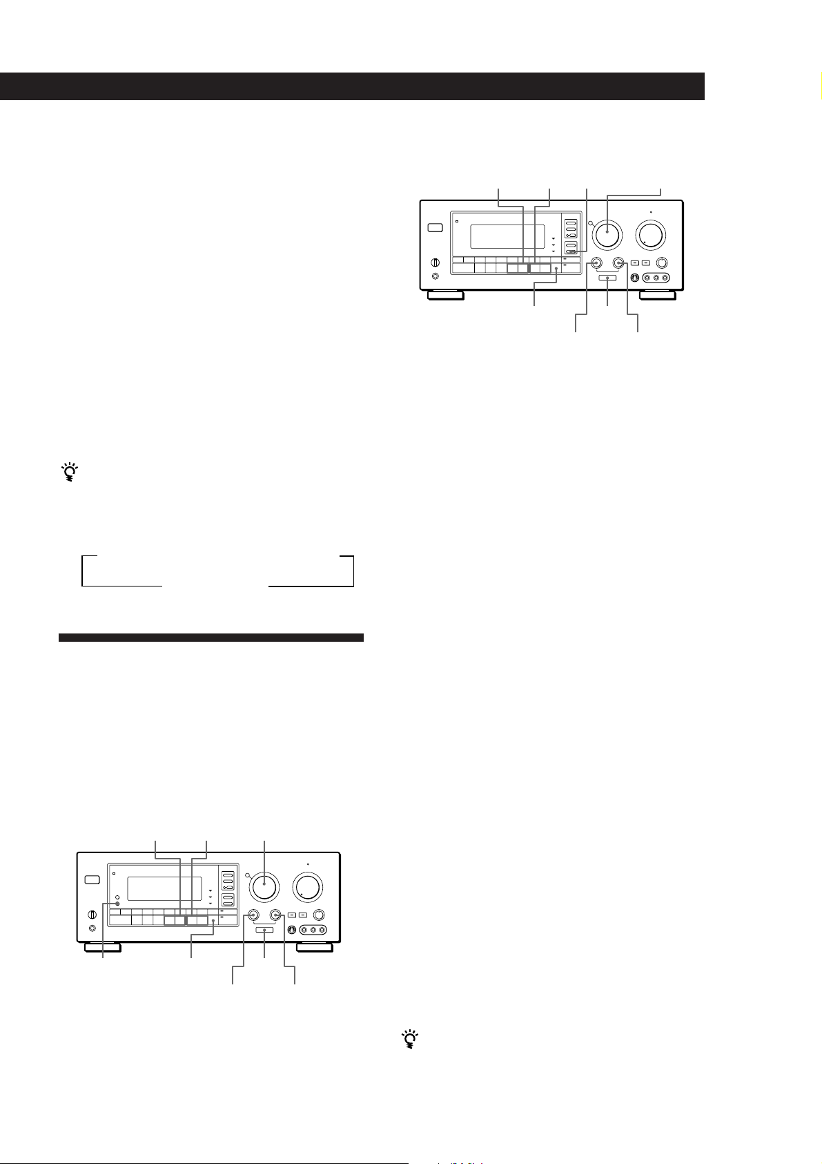
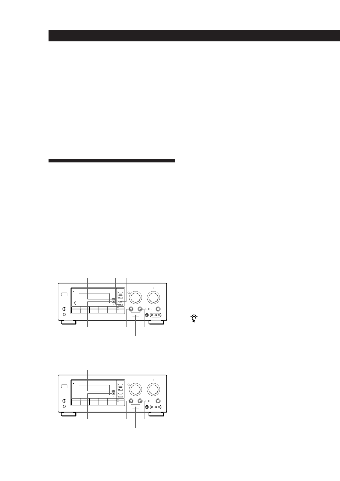
Indexing preset stations
You might find that too many preset stations make it
hard to find the station you want. This receiver
includes a feature that lets you group preset stations by
name (station index) using up to 8 characters.
For example, if you label all of your preset jazz stations
“JAZZ,” selecting “JAZZ” lets you skip other presets
and scan only the stations labeled “JAZZ.” Note that
you cannot assign more than one station index name to
each preset station.
1 Select TUNER.
The last station you received is tuned in.
Indexing
You can index preset stations and then use the index
names to scan specific stations in the preset memory.
You can also use the index feature to label program
sources so that the receiver displays the names of the
components you connected, for example, “VHS”.
STR-GA8ES
INDEX
– / +
DISPLAY
PRESET
– / +
MEMORY
FUNCTION
DPC
MODE
POSITIONCHARACTER
2 Tune in the preset station you want to create an
index for.
If you are not familiar with how to tune in preset
stations, see “Tuning preset stations (preset
tuning)” above.
3 Press DPC MODE repeatedly until the INDEX
indicator lights up.
4 Create a station index name by using the
DIGITAL PROCESSING CONTROL knobs as
follows:
Turn CHARACTER to select a character.
Then turn POSITION to move the cursor to the
next position.
To insert a space, turn CHARACTER until a blank space
appears in the display, the space is between " and A.
The station index is stored automatically.
If you’ve made a mistake
Turn POSITION until the character you want to change
flashes. Then select the right character.
5 Repeat Steps 2 to 4 to assign index names to other
stations.
You can display either the index name or frequency
Each time you press DISPLAY, the display switches
between the frequency and the index name.
(continued)
13
EN
Page 14
14
EN
Receiver Operations
Scanning indexed stations (index tuning)
Once you select a station index, you can scan all the
stations with that station index.
1 Select TUNER.
The last station you received is tuned in.
2 Press DISPLAY so that the index mode appears in
the display.
The station index for the last station you received
appears in the display.
If “_ _ _ _ ” appears
The station does not have an station index.
3 Press INDEX + or – to select the station index you
want to scan.
4 Press PRESET + or – to select the station you want
receive.
To select a different station index
Press INDEX + or – to select the one you want, then press
PRESET + or – to select a station.
Indexing program sources
This feature is useful when, for example, you have
more than one VCR: you can label one VCR as “VHS”
and label the other as “8mm.” Then, you can have the
receiver display the index names so you can tell which
VCR you are using. This feature also comes in handy if
you connect a component to jacks designed for another
component (for example, connecting a second CD
player to the DAT/MD jacks or a DVD player to the
LD jacks).
1 Select the FUNCTION you want to label.
2 Press DPC MODE repeatedly until the INDEX
indicator lights up.
3 Create a station index name by using the
DIGITAL PROCESSING CONTROL knobs as
follows:
Turn CHARACTER to select a character, then
turn POSITION to move the cursor to the next
position.
To insert a space, turn CHARACTER until a blank space
appears in the display, the space is between " and A.
The station index is stored automatically.
If you’ve made a mistake
Turn POSITION until the character you want to change
flashes. Then select the right character.
You can display either the index or function name
Each time you press DISPLAY, the display switches
between the function name and the index name.
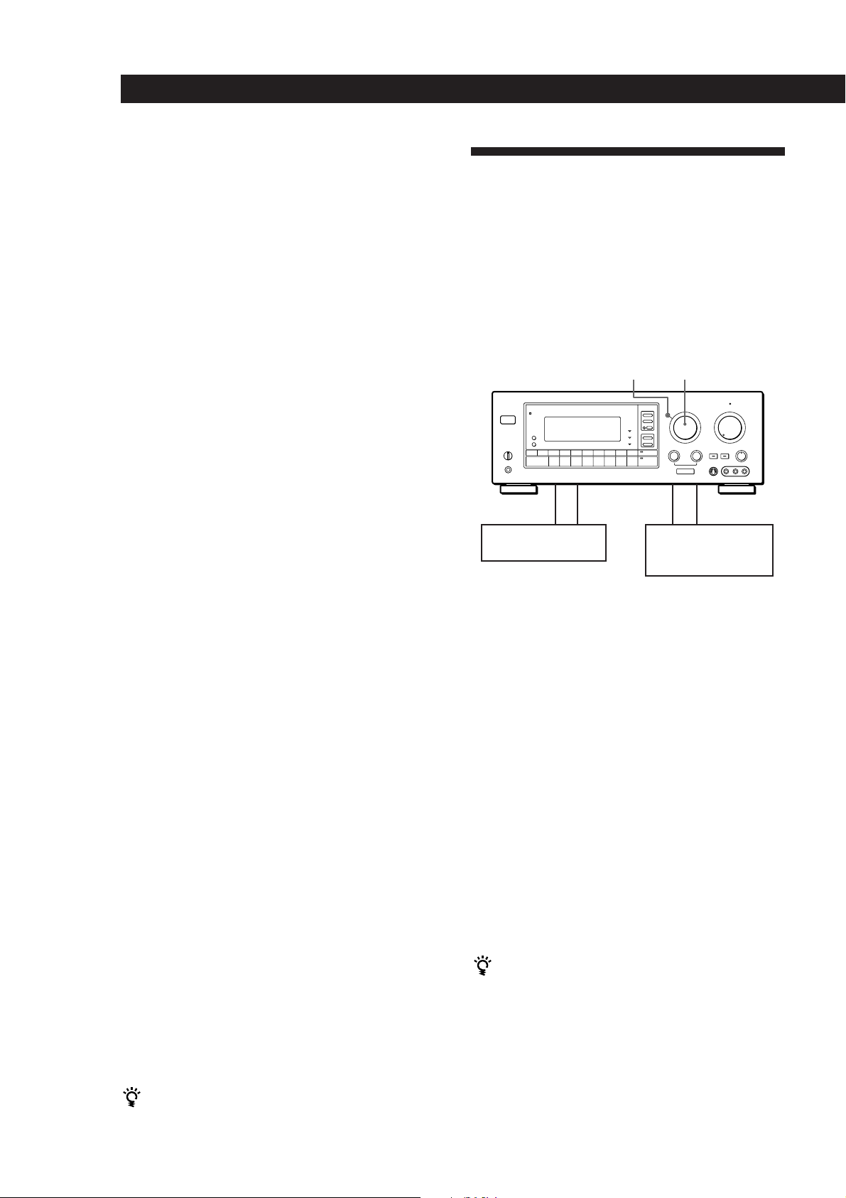
Recording
This receiver makes it easy to record to and from the
components connected to the receiver. You don’t have
to connect playback and recording components
directly: once you select a program source on the
receiver, you can record and edit as you normally
would using the controls on each component.
Before you begin, make sure you’ve connected all
components properly.
MODE
c
ç
Playback component
(program source)
ç: Audio signal flow
c: Video signal flow
Recording on an audio tape or MiniDisc
You can record on a cassette tape, Digital Audio Tape
or MiniDisc using the receiver. See the instruction
manual of your cassette deck, DAT deck, or MD deck if
you need help.
1 Turn FUNCTION to select the program source to
be recorded.
2 Set the component to be ready for playing.
For example, insert a CD into the CD player.
3 Insert a blank tape into the recording deck and
adjust the recording level, if necessary.
4 Start recording on the recording deck and then
start playing the component.
You can monitor the sound being recorded
If you connected a 3-head tape deck to the TAPE
MONITOR jacks, press TAPE MONITOR. “TAPE”
appears in the display and you can hear the sound
being recorded.
Note
When you record on a DAT or MD connected to the DAT/
MD REC OUT jacks, sound adjustments do not effect the
recording.
FUNCTION
c
ç
Recording component
(tape deck, DAT deck,
MD deck, VCR)
Page 15
Receiver Operations
Recording on a video tape
You can record from a VCR, a TV, or a LD player using
the receiver. You can also add audio from a variety of
audio sources when editing a video tape. See your VCR
or LD player’s instruction manual if you need help.
1 Turn FUNCTION to select the program source to
be recorded.
2 Set the component to be ready for playing.
For example, insert the laser disc you want to
record from into the LD player.
3 Insert a blank video tape into the recording VCR
(VIDEO 1 or VIDEO 2).
4 Start recording on the recording VCR and then
start playing the video tape or laser disc you want
to record.
Replacing audio while copying a video tape
or laser disc
You can add audio from a variety of sources when
editing a video tape. See your VCR or LD player’s
instruction manual if you need help.
To record other audio on a specific part of video
1 Pause the video the point where you want to record the
other audio.
2 Press MODE to select “AUDIO MODE”, then use
FUNCTION (or TAPE MONITOR) to select the audio
source you desire.
3 Start recording on the recording VCR, release the pause
mode and start playing the audio source you want to
record.
To resume recording the sound of the original playback
source, press the SYSTEM CONTROL/FUNCTION button
on the remote for that component.
Using the Sleep Timer
You can set the receiver to turn off automatically at a
time you specify.
SLEEP
1 Turn FUNCTION to select the video program
source to be recorded.
2 Press MODE repeatedly so that “AUDIO MODE”
appears in the display.
The current video signal is fixed and you can
select audio from any other source (except AC-3)
whithout changing the current video signal.
3 Use FUNCTION (or TAPE MONITOR) to select
the audio you desire.
If you want to change the video program selected in
step 1, press MODE to select “VISUAL MODE” and you
can select video from another source while maintaining
the current audio signal.
4 Prepare the respective video and audio sources
for playback.
5 Insert a blank video tape into the recording VCR.
6 Start recording on the recording VCR and then
start playing both the video and audio sources
you want to record.
Note
If you do not select the audio or video source within 8
seconds of pressing MODE, the “AUDIO MODE” or
“VISUAL MODE” is cancelled and the audio or video source
will not be fixed. In this case, press MODE again to display
the mode you desire. The mode changes as follows:
VISUAL MODE / AUDIO MODE / off
Press SLEEP on the remote while the power is on.
Each time you press SLEEP, the time changes as shown
below.
n 2:00:00 n 1:30:00n 1:00:00 n 0:30:00 n OFF
The display dims after you specify the time.
You can freely specify the time
Press SLEEP first, then specify the time you want using
DIGITAL PROCESSING CONTROL buttons , , ,
or . The sleep time changes in 1 minute intervals. You
can specify up to 5 hours.
You can check the time remaining before the
receiver turns off
Press SLEEP. The remaining time appears in the
display.
15
EN
Page 16
Using Surround Sound
Using Surround Sound
Introduction
The STR-GA8ES and STR-GA7ES are provided with a
variety of surround features which allow you to listen
to a wide range sources in surround sound. They are
also equipped with several adjustable parameters to let
you customize the sound to your preference.
To use a pre-programmed sound field
See “Using Pre-programmed Sound Fields” on this
page. This section describes how to recall the sound
fields and provides a description of each sound field.
To take advantage of Dolby Pro Logic
Surround sound
See “Getting the Most Out of Dolby Pro Logic
Surround Sound” on page 18. This section describes
how to adjust the levels of your speaker system and
customize the PRO LOGIC sound fields.
To create your own sound field
See “Taking Advantage of the Sound Fields” on page
19 and “Customizing the Sound Fields” on page 20.
“Taking Advantage of the Sound Fields” describes
how the various parameters affect the sound.
“Customizing the Sound Fields” describes how adjust
the parameters and provides a chart showing which
parameters are available in each sound field.
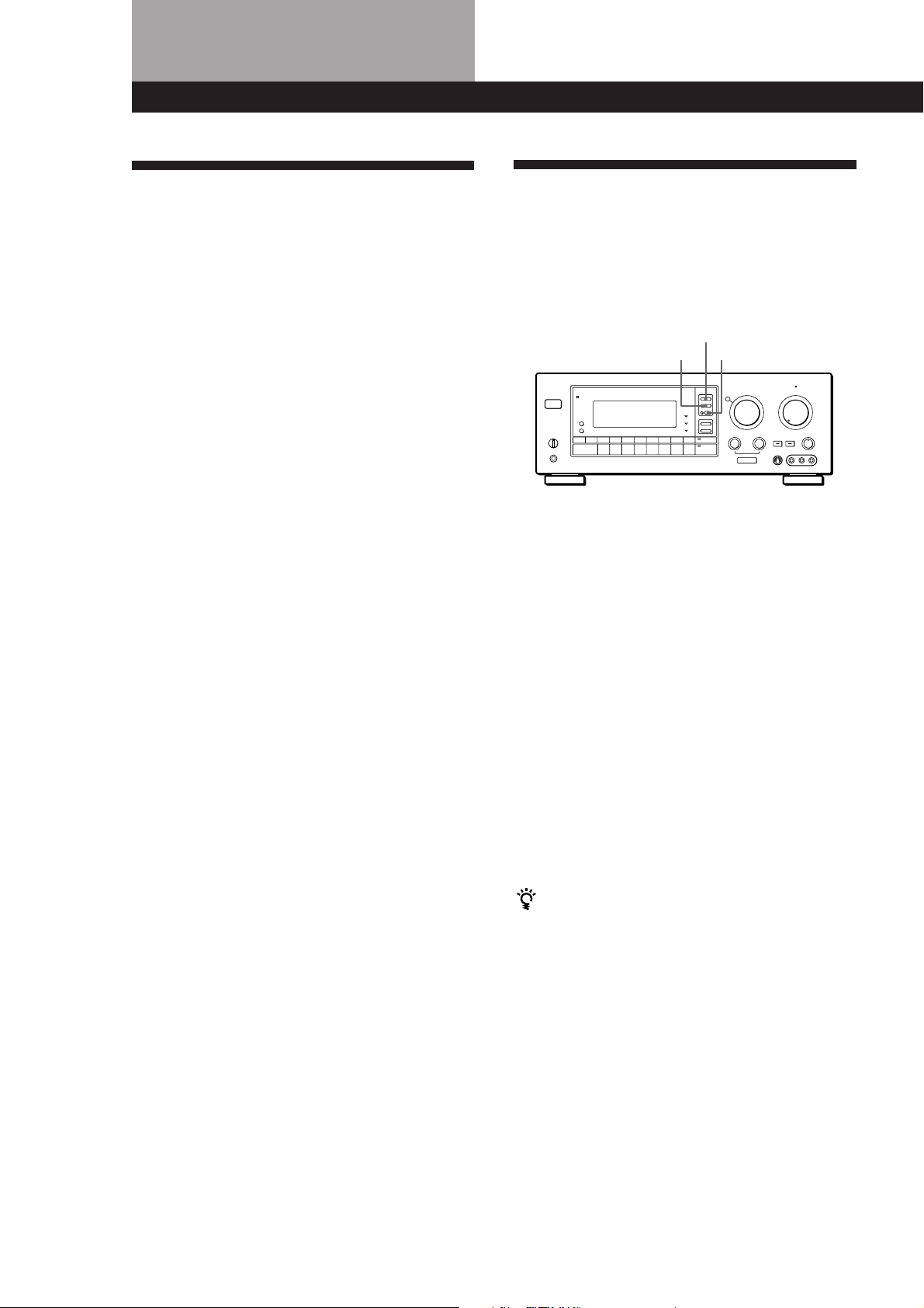
Using Pre-programmed Sound
Fields
You can take advantage of surround sound simply by
selecting one of the pre-programmed sound fields
according to the program you want to play.
SOUND FIELD
ON/OFF
MODEGENRE
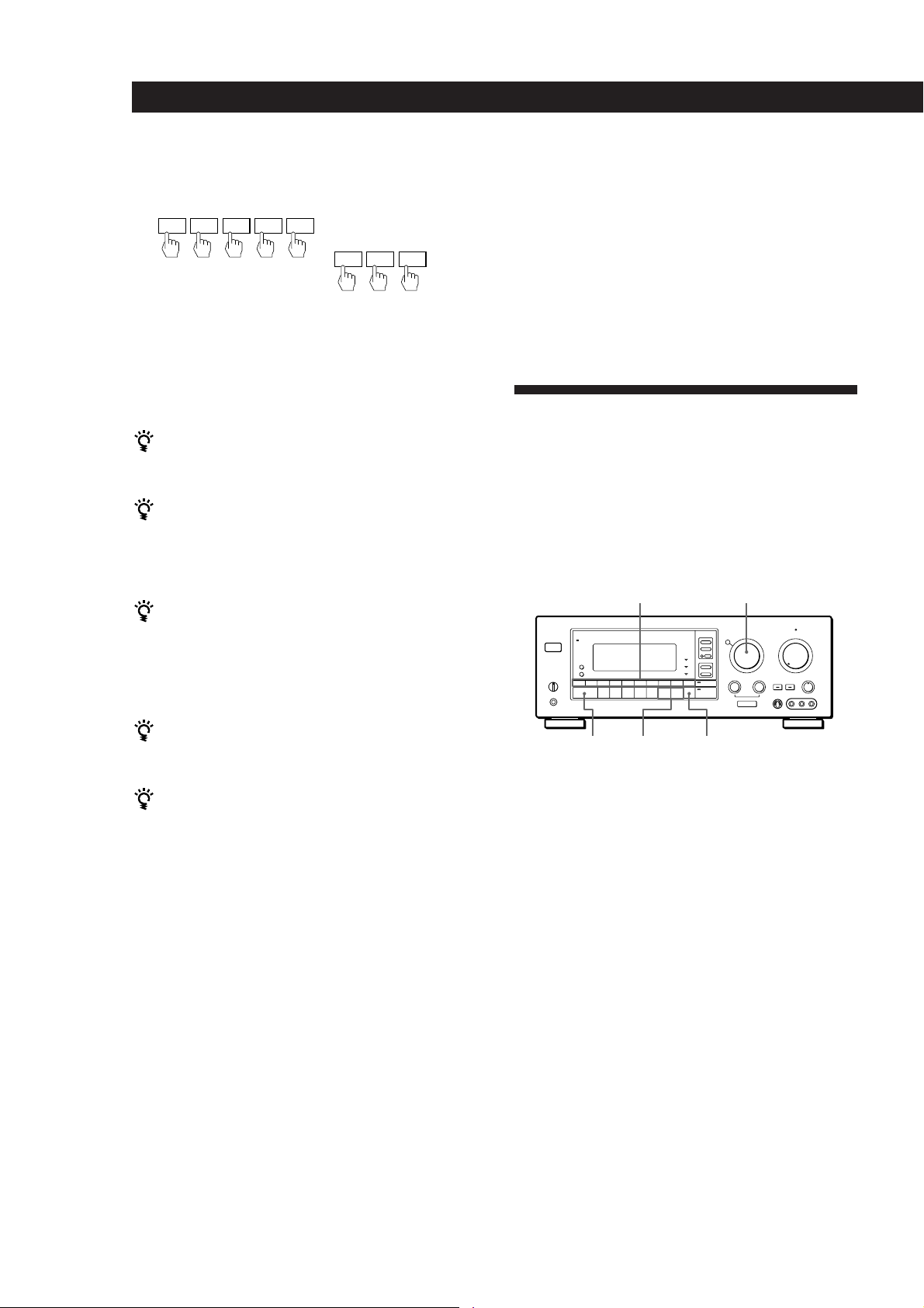
1 Press SOUND FIELD ON/OFF to turn on the
sound field.
One of the indicators lights up in the display.
2 Press GENRE to select the type of sound field you
desire.
3 Press MODE to select the mode you desire from
the respective genre.
Refer to the chart shown at right.
To play without surround effects
Select “Acoustic” from MUSIC 2. The surround effects are
defeated but you can still adjust the equalizer or tone (see
page 20).
16
EN
For additional information regarding
surround sound
See the “Glossary” on pages 27 and 28.
To turn off the sound fields
Press SOUND FIELD ON/OFF.
You can find Dolby Surround-encoded software by
looking at the packaging
However, some videos and laser discs may use Dolby
Surround sound even if it's not indicated on the
package.
Note
Make sure to select both speakers (A+B) with the SPEAKERS
selector when you use two sets of speakers; otherwise, you
will not obtain the full surround effect.
Page 17

Using Surround Sound
Sound fields for STR-GA8ES
GENRE MODE To
PRO LOGIC PRO LOGIC Decode programs processed with Dolby Surround.
ENHANCED Obtain additional output from rear speakers when decoding Dolby Surround
MOVIE SMALL THEATER
MEDIUM THEATER Add the acoustic reflections of theater to decoded Dolby Surround signals.
LARGE THEATER
MONO MOVIE Create a theater-like environment from movies with monaural soundtracks.
MUSIC 1 SMALL HALL
MEDIUM HALL Reproduce the acoustics of a rectangular concert halls. Ideal for soft acoustic
LARGE HALL
SMALL OPERA HOUSE
MEDIUM OPERA HOUSE Reproduce the acoustics of an opera house. Ideal for musicals and operas.
LARGE OPERA HOUSE
MUSIC 2 SMALL JAZZ CLUB Reproduce the acoustics of a jazz club.
LARGE JAZZ CLUB
SMALL CHURCH Reproduce the acoustics of a church
LARGE CHURCH
SMALL LIVE HOUSE Reproduce the acoustics of a live house
LARGE LIVE HOUSE
KARAOKE Reduce the vocal tracks of stereo music sources.
ACOUSTIC Reproduce normal 2 channel stereo with equalization (EQ).
SPORTS ARENA Reproduce the feeling of a large concert arena. Great for Rock and Roll.
STADIUM Reproduce the feeling of a large open-air stadium. Great for electric sounds.
GAME GAME 1 Obtain maximum audio impact from video game software.
GAME 2 Obtain maximum audio impact from monaural video game software.
programs.
sounds.
Sound fields for STR-GA7ES
GENRE MODE To
PRO LOGIC PRO LOGIC Decode programs processed with Dolby Surround.
ENHANCED Provide additional output to the rear speakers after decoding the Dolby Surround
program
MOVIE SMALL THEATER Add the acoustic reflections of theater to decoded Dolby Surround signals.
LARGE THEATER
MONO MOVIE Create a theater-like environment from movies with monaural soundtracks.
MUSIC 1 SMALL HALL Reproduce the acoustics of a rectangular concert hall. Ideal for soft acoustic sounds.
LARGE HALL
MUSIC 2 KARAOKE Reduce the vocal tracks of stereo music sources.
ACOUSTIC Reproduce normal 2 channel stereo with tone control (TONE).
SPORTS ARENA Reproduce the feeling of a large concert arena. Great for Rock and Roll.
STADIUM Reproduce the feeling of a large open-air stadium. Great for electric sounds.
GAME GAME Obtain maximum audio impact from video game software.
17
EN
Page 18
Using Surround Sound
Getting the Most Out of Dolby
Pro Logic Surround Sound
To obtain the best possible Dolby Pro Logic Surround
sound, first select the center mode according to your
speaker system. Then, adjust the sound parameters of
the PRO LOGIC sound field.
Selecting the center mode
The receiver offers you four center modes:
PHANTOM, 3 CHANNEL LOGIC, NORMAL, and
WIDE. Each mode is designed for a different speaker
configuration. Select the mode that best suits your
speaker system configuration.
1 Press SOUND FIELD ON/OFF to turn on the
sound fields.
Note that you must have at least one additional pair of
speakers and/or one center speaker to do the following
adjustments.
SOUND FIELD
ON/OFF
MODEGENRE
LEVELPARAMETER
DPC
MODE
TEST TONE
REAR
LEVEL (+/–)
CENTER
LEVEL (+/–)
GENRE
SOUND FIELD
ON/OFF
MODE
DPC MODE
DIGITAL
PROCESSING
CONTROL
CTR MODE
SURROUND
indicator
0)=+
9(p P r
2 Press GENRE to select the PRO LOGIC sound
field.
3 Press CTR MODE repeatedly until the center
mode you want appears in the display. Select the
center mode by referring to the following chart.
If you have
Front and rear
speakers, no
center speaker
Front and center
speakers, no rear
speaker
Front and rear
speakers, and a
small center
speaker
Front and rear
speakers, and a
center speaker
equivalent to your
front speakers
Select
PHANTOM
3 CH LOGIC
(3 Channel
Logic)
NORMAL
WIDE
So that
The sound of the
center channel is
output from the front
speakers.
The sound of the rear
channel is output
from the front
speakers.
The bass sound of the
center channel is
output from the front
speakers (because a
small speaker cannot
produce enough
bass).
For “complete”
Dolby Pro Logic
Surround sound.
Adjusting the speaker volume
The test tone feature lets you set the volume of your
speakers to the same level. (If all of your speakers have
equal performance, you don’t have to adjust the
speaker volume.)
18
Using the controls on the remote lets you adjust the
volume level from your listening position.
1 Press TEST TONE on the remote.
You will hear the test tone from each speaker
sequentially.
EN
Page 19

2 Adjust the volume levels so that you hear the test
tone from each speaker at the same volume level
when you are in your listening position:
• To adjust the volume between the front right
and front left speakers, use the BALANCE
control on the front of the main unit.
• To adjust the level of center speaker, press
CENTER LEVEL + or – on the remote.
• To adjust the level of rear speakers, press
REAR LEVEL + or – on the remote.
3 Press TEST TONE on the remote to turn off the
test tone.
Using Surround Sound
Taking Advantage of the
Sound Fields (STR-GA8ES)
This receiver uses digital signal processing to
reproduce the sound effects of various listening
environments, such as a movie theaters and concert
halls (etc.). By adjusting the surround parameters you
can control thes sound elements to create a custom
listening environment.
Room Size Simulation (ROOM SIZE)
You can adjust all speakers at one time
Adjust MASTER VOL.
Adjusting the delay time
You can make the surround sound more effective by
delaying the output from the rear speakers (delay
time). You can adjust the delay time in 0.1 ms steps (for
STR-GA8ES) or 5 ms steps (for STR-GA7ES) within the
range of 15 to 30 ms. For example, if you’ve placed the
rear speakers in a large room or apart from your
listening position, set the delay time shorter.
1 Start playing a program source encoded with
Dolby surround sound.
2 Press DPC MODE until the SURROUND indicator
lights up.
3 Rotate the PARAMETER knob to select the delay
time.
The current delay time appears in the display.
4 Rotate the LEVEL knob to adjust the delay time.
Before sound reaches our ears, it is reflected many
times between the left and right walls, ceiling, and
floor. In a large room, sound takes more time to
bounce from one surface to another than in a smaller
room.
The ROOM SIZE parameter lets you control the
spacing of the early reflections to simulate a sonically
larger (L), or smaller (S) room. The mid-point
designates a standard room with no adjustment.
Wall Material Simulation (WALL TYPE)
When sound is reflected off soft material, such as
curtain, the high frequency elements are reduced. A
hard wall is highly reflective and does not significantly
affect the frequency response of the reflected sound.
The WALL TYPE parameter lets you control the level
of the high frequencies to alter the sonic character of
your listening environment by simulating a softer (S),
or harder (H) wall. The mid-point designates a neutral
wall (made of wood).
Seat Position Simulation
(FRONT/REAR and LEFT/RIGHT)
Adjusting the equalizer (STR-GA8ES) or
tone (STR-GA7ES)
You can adjust the tone of the speakers.
Follow the procedure described in “Adjusting the
equalizer” or “Adjusting the tone controls” on page 20.
If you sit in the front of a room, you hear more direct
sound from the front speakers. As you move to the
rear, the reflected sound increases. Similarly, the
reflected sound changes when you move from left to
right, and vice versa.
The FRONT/REAR and LEFT/RIGHT parameters let
you control the balance of direct and reflected sound to
simulate your listening position.
In the FRONT/REAR parameter, “F” signifies the front
of the room and “R” signifies the rear. The mid-point
designates the center.
In the LEFT/RIGHT parameter, “L” signifies the left
side of the room and “R” signifies the right side. The
mid-point designates the center.
(continued)
19
EN
Page 20
Using Surround Sound
Reverberation Time (REVERB)
This parameter adjusts the length of time required for
the reverberation (echoes) generated from a given
sound to attenuate –60 dB.
You can choose shorter (S) or longer (L) reverberation
times.
Note
The EFFECT parameter allows you to adjust the overall
presence of the sound field.
Customizing the Sound Fields
Each sound field is composed of an equalizer
(STR-GA8ES) or tone controls (STR-GA7ES) and
surround sound parameters — variables of sound, that
create the sound image. You can customize the sound
fields by adjusting some of the sound parameters to
suit your listening situation. See the charts on page 22
for the parameters available in each sound field.
Once you customize the sound fields, they are stored in
memory unless the receiver is unplugged for about 1
week.
STR-GA8ES
SURROUND
indicator
EQUALIZER
SLOPEBAND
Before you get started
Select the sound field you want to customize and start
playing a program.
Adjusting the equalizer (STR-GA8ES)
Adjust the tone of the front, center and rear speakers
for optimum sound. You can adjust the tone of all
sound fields, including Dolby Surround.
1 Press SOUND FIELD ON/OFF so the name of the
previously selected sound field appears in the
display.
2 Press DPC MODE so that the “EQUALIZER”
indicator lights up.
3 Press EQUALIZER BAND to select a frequency
band: B (bass), M (midrange), or T (treble).
4 Press SLOPE to select the type of adjustment you
want: NARROW (to adjust a specific frequency),
MEDIUM (to a small group of frequencies), or
WIDE (to adjust a broad range of frequencies).
5 Rotate the FREQUENCY digital processing
control knob to select the frequency you want to
adjust.
6 Use the EQ LEVEL digital processing control
knob to raise or lower the level of the selected
frequency.
20
EN
STR-GA7ES
EQUALIZER
indicator
SURROUND
indicator
TONE
indicator
PARAMETER
FREQUENCY
PARAMETER
BASS/TREBLE
DPC
MODE
DPC
MODE
LEVEL
EQ LEVEL
LEVEL
TONE LEVEL
7 Repeat steps 3 through 6 for other frequency
bands until you obtain the equalization curve you
desire.
You can turn off the tone adjustments without
erasing them
Press EQ/TONE ON/OFF on the remote to turn the
tone parameter off or on. The tone adjustments and on/
off setting are stored in each sound field.
Adjusting the tone controls (STR-GA7ES)
Adjust the tone of the front, center and rear speakers
for optimum sound. You can adjust the tone of all
sound fields, including Dolby Surround.
1 Press SOUND FIELD ON/OFF so the name of the
previously selected sound field appears in the
display.
2 Press DPC MODE so that the “TONE” indicator
lights up.
3 Rotate the BASS/TREBLE digital processing
control knob to select “BASS” or “TREBLE”.
Page 21

Use the TONE LEVEL digital processing control
4
knob to raise or lower the level.
5 Repeat steps 3 and 4 as necessary to obtain the
tone you desire.
You can turn off the tone adjustments without
erasing them
Press EQ/TONE ON/OFF on the remote to turn the
tone parameter off or on. The tone adjustments and on/
off setting are stored in each sound field.
Adjusting surround sound parameters
Change the surround parameters to fit your listening
situation. Refer to the chart on the next page for
parameters you can adjust in each sound field.
To adjust the parameters of the PRO LOGIC sound
field, see “Getting the Most Out of Dolby Pro Logic
Surround Sound” on page 18.
Using Surround Sound
1 Press DPC MODE repeatedly until the
SURROUND indicator lights up.
2 Use the PARAMETER digital processing control
knob to select the parameter you want.
3 Use the LEVEL digital processing control knob to
adjust the level of the parameter.
The adjusted parameters are stored automatically.
Note
If you make new adjustments to a sound field, the
previous settings are replaced by the new ones.
Resetting customized sound fields to the
factory settings
1 If the power is on, press POWER to turn off the
power.
2 Hold down SOUND FIELD ON/OFF and press
POWER.
“SURR CLEAR!” appears in the display and all
the sound fields are reset at once.
21
EN
Page 22

Using Surround Sound
Adjustable parameters for STR-GA8ES
EFFECT REAR CENTER ROOM WALL FRONT LEFT REVERB
GENRE MODE EQ LEVEL LEVEL LEVEL SIZE TYPE BACK RIGHT DELAY TIME
PRO LOGIC PRO LOGIC rrr r
ENHANCED rrr r
MOVIE SMALL THEATER rr r r r r r r r
MEDIUM THEATER rr r r r r r r r
LARGE THEATER rr r r r r r r r
MONO MOVIE rr r r r r r r
MUSIC 1 SMALL HALL rr r r r r r r
MEDIUM HALL rr r r r r r r
LARGE HALL rr r r r r r r
SMALL OPERA HOUSE rr r r r r r r
MEDIUM OPERA HOUSE rr r r r r r r
LARGE OPERA HOUSE rr r r r r r r
MUSIC 2 SMALL JAZZ CLUB rr r r r r r r
LARGE JAZZ CLUB rr r r r r r r
SMALL CHURCH rr r r r r r r
LARGE CHURCH rr r r r r r r
SMALL LIVE HOUSE rr r r r r r r r
LARGE LIVE HOUSE rr r r r r r r r
KARAOKE rr r r r r r r
ACOUSTIC r
SPORTS ARENA rr r r r r r r
STADIUM rr r r r r r r
GAME GAME 1 rr r r r r r r
GAME 2 rr r r r r r r
22
Adjustable parameters for STR-GA7ES
EFFECT REAR CENTER
GENRE MODE TONE LEVEL LEVEL LEVEL DELAY
PRO LOGIC PRO LOGIC rrrr
ENHANCED rrrr
MOVIE SMALL THEATER rr r r
LARGE THEATER rr r r
MONO MOVIE rr r
MUSIC 1 SMALL HALL rr r
LARGE HALL rr r
MUSIC 2 KARAOKE rr r
ACOUSTIC r
SPORTS ARENA rr r
STADIUM rr r
GAME GAME rr r
EN
Page 23

Advanced Remote Operations
0)=+
Operating One Component
While Using Another
(background operation)
You can temporality operate other components while
listening to or watching a program.
Numeric
buttons
BACKGROUND
1 Hold down BACKGROUND.
2 Press both the corresponding numeric button of
the component you‘re going to use (see the table
below) and one of the following buttons at the
same time; VISUAL POWER, TV/VIDEO, CH
PRESET +/–, ANT TV/VTR, D.SKIP, (, 9, p,
0/), =/+, P, r.
0)=+
Changing the Factory Setting
of a FUNCTION Button
If the factory settings of the FUNCTION buttons (page
11) don’t match your system components, you can
change them. For example, if you connect a Sony LD
player to the VIDEO 2 jacks, you can assign the VIDEO
2 button to set the remote to control the LD player.
Note that the settings of the TUNER and PHONO
buttons cannot be changed.
SYSTEM
CONTROL/
FUNCTION
Numeric
buttons
1 Holding down the SYSTEM CONTROL/
FUNCTION button whose function you want to
change (VIDEO 2, for example).
Example:To start recording on a tape deck while
listening to a CD
While holding down BACKGROUND,
press 4 (or 5) and press r.
The numeric buttons are assigned to select the
functions as follows:
Numeric button Operates
1 CD player
2 DAT deck
3 MD deck
4 Tape deck A
5 Tape deck B
6 LD player
7 VCR (remote control mode VTR 1*)
8 VCR (remote control mode VTR 2*)
9 VCR (remote control mode VTR 3*)
0TV
>10 DBS
2 Press the corresponding numeric button of the
component you want to assign to the SYSTEM
CONTROL/FUNCTION button (6 - LD player,
for example).
For the numeric buttons, see the table in
“Operating One Component While Using
Another.”
Now you can use the VIDEO 2 button to control
your Sony LD player.
To reset the setting to the factory setting
Repeat the above procedure.
* Sony VCRs are operated with a VTR 1, 2 or 3 setting.
These correspond to Beta , 8mm and VHS respectively.
23
EN
Page 24

Advanced Remote Operations
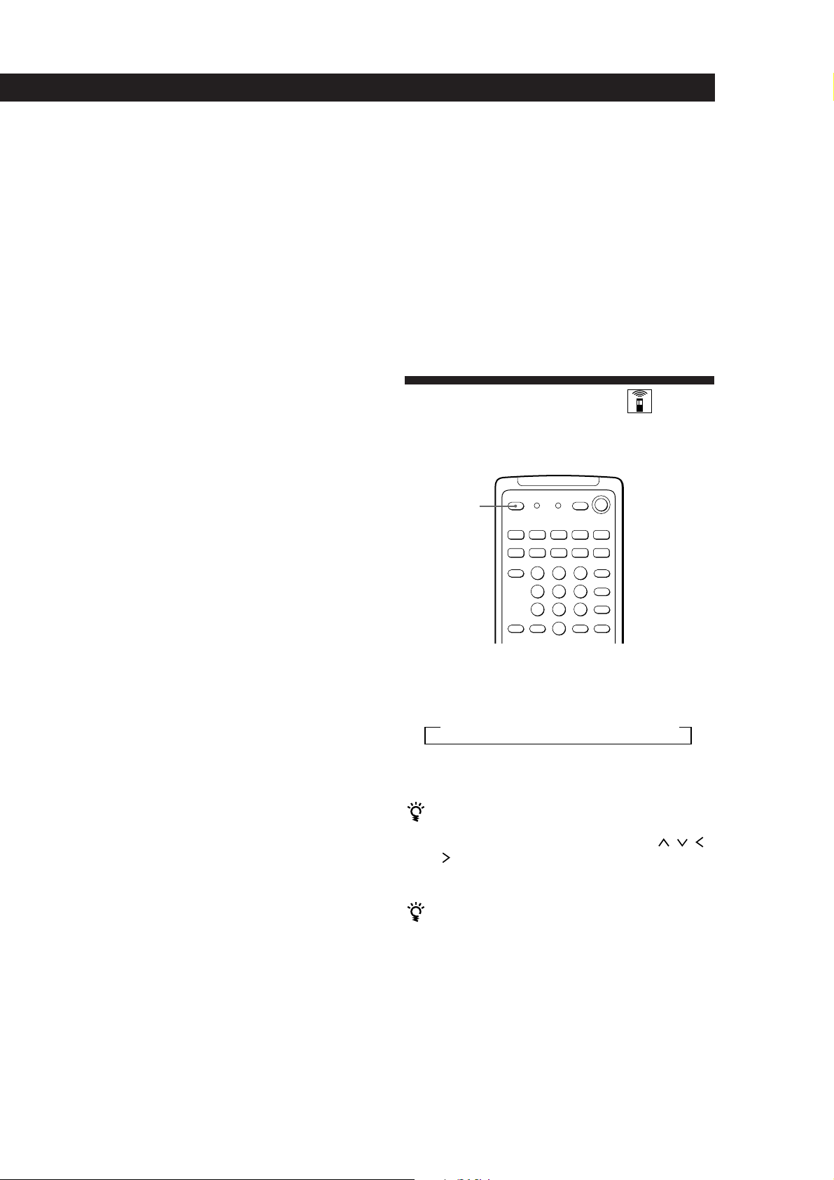
Programming the Remote
The RM-P362 remote included with the STR-GA8ES
and STR-GA7ES can control non-Sony components by
“learning” the control signals from their remotes. Once
this remote learns the other components signals, you
can use these components as part of your system.
Additionally, if you have any Sony components that
fail to operate with this remote, use this programming
function. This remote can “learn” signals only from
other infrared wireless remotes. Before you program
signals, make sure that the two remotes:
• Face straight at each other (see Step 3 below)
• Are placed at a distance of about 2 inches (5 cm)
• Are not moved during programming
4 On the other remote, select the function that the
receiver’s remote is to “learn” and hold down its
button until the LEARN indicator lights steadily.
5 Repeat Steps 3 and 4 to program other buttons.
Note that each button can only “learn” one signal
from another remote.
6 Press LEARN.
After the LEARN indicator turns off, you can
control the other component with the
programmed buttons.
When you program the recording signal
While holding down the r button on the receiver’s
remote and press the record button on the other remote.
LEARN
indicator
BACKGROUND
0)=+
9(p P r
LEARN
SYSTEM
CONTROL/
FUNCTION
1 Press the SYSTEM CONTROL/FUNCTION
button of the component you want to program.
For example, if you want to program a CD
player’s remote, press CD.
2 Press LEARN to turn on the LEARN indicator.
3 Press the button on this unit’s remote that is to
“learn” the signal from the other remote.
The LEARN indicator flashes slowly.
Use only the shaded buttons shown above (see
“Remote Button Descriptions” on page 30 for the
buttons you can use to operate each component).
Other remote
If you cannot successfully program signals, check the
following:
• If the LEARN indicator does not light up at all, the
batteries are weak. Replace both batteries.
• If the LEARN indicator does not flash or light up in
Step 3 or 4, there is interference. Clear the signal as
described in “Clearing the programmed signal”
below and program again from the beginning.
• The two remotes are placed too far apart. Make sure
they are only 2 inches apart.
• If you don’t proceed to the following steps within
about 1 minute during Steps 2 and 3, the remote
automatically exits learning mode. Start again from
Step 2.
• If the memory in the remote has become full, (If you
program signals of Sony components, you can store
about 60 signals.) you can program a new signal on a
previously programmed button, but the new signal
will replace the previously programmed one.
Notes
• You cannot turn on programmed components by pressing
a SYSTEM CONTROL/FUNCTION button. You have to
turn on the component's power switch.
• Do not program remote signals of air conditioners or other
household appliances.
Clearing the programmed signal
To clear the programmed signals, do the following.
The button's functions are reset to the factory-preset.
24
EN
Receiver’s remote
About 2 inches
(5 cm)
If the LEARN indicator flashes rapidly
You cannot use the button you’ve pressed.
1 Press LEARN to turn on the LEARN indicator.
2 While holding down BACKGROUND, hold down
the button to be cleared until the LEARN
indicator turns off.
Page 25

Additional Information
Troubleshooting
If you experience any of the following difficulties while
using the receiver, use this troubleshooting guide to
help you remedy the problem. Should any problem
persist, consult your nearest Sony dealer.
There’s no sound or only a very low-level sound is heard.
/ Check that the speakers and components are
connected securely.
/ Make sure you select the correct component
on the receiver.
/ Make sure you set the SPEAKERS selector
correctly.
/ Make the POWER SWAP selector is set to the
correct position.
/ Press MUTING on the remote if the MUTING
indicator turns on.
/ The protective device on the receiver has been
activated because of a short circuit.
(“PROTECTOR” flashes.) Turn off the
receiver, eliminate the short-circuit problem
and turn on the power again.
The left and right sounds are unbalanced or reversed.
/ Check that the speakers and components are
connected correctly and securely.
/ Adjust the BALANCE control.
Severe hum or noise is heard.
/ Check that the speakers and components are
connected securely.
/ Check that the connecting cords are away
from a transformer or motor, and at least 10
feet (3 meters) away from a TV set or
fluorescent light.
/ Place your TV away from the audio
components.
/ Make sure you connect a ground wire to the
antenna ground terminal.
/ The plugs and jacks are dirty. Wipe them
with a cloth slightly moistened with alcohol.
No sound is heard from the center speaker.
/ Select a PRO LOGIC or MOVIE (except
MONO THEATER) sound field (see page 17).
/ Select the appropriate center mode
(see page 18).
/ Adjust the speaker volume appropriately
(see page 18).
Recording cannot be made.
/ Check that the components are connected
correctly.
/ Select the source component with the
function buttons.
Additional Information
No sound or only a very low-level sound is heard from
the rear speakers.
/ Turn on the sound field function.
/ Select the appropriate center mode
(see page 18).
/ Adjust the speaker volume appropriately
(see page 18).
/ Make sure you turned on the sound field
function.
Radio stations cannot be tuned in.
/ Check that the antennas are connected
securely. Adjust the antennas and connect an
external antenna if necessary.
/ The signal strength of the stations is too weak
(when you tune in with automatic tuning).
Use direct tuning.
/ Make sure you set the tuning interval
correctly (when you tune in AM stations with
automatic tuning) (see pages 12 and 27).
/ No stations have been preset or the preset
stations have been cleared (when you tune in
with scanning preset stations). Preset the
stations (see page 12).
/ Make sure to set the display mode to
“NORMAL MODE” (when you tune with
automatic tuning).
Surround effect cannot be obtained.
/ Turn on the sound field function.
/ Make sure that the SPEAKERS selector is set
to A+B when you use two sets of front
speakers.
No picture or an unclear picture is seen on the TV screen.
/ Select the appropriate function on the
receiver.
/ Set your TV to the appropriate input mode
(press TV/VIDEO on the remote for Sony
TVs).
/ Place your TV away from the audio
components.
The remote does not function.
/ Point the remote at the remote sensor g on
the receiver.
/ Remove the obstacles in the path of the
remote and the receiver.
/ Replace both batteries in the remote with new
ones if they are weak.
/ Make sure you select the correct function on
the remote.
/ Pressing TV CONTROL ON sets the remote
to operate the TV only. In this case, press one
of the SYSTEM CONTROL/FUNCTION
buttons before operating the receiver (etc.).
25
EN
Page 26

Additional Information
26
EN
Specifications
Audio power specifications
POWER OUTPUT AND TOTAL
HARMONIC DISTORTION
With 8-ohm load, both
channels driven, from 20 20,000 Hz, STR-GA8ES rated
120 watts, STR-GA7ES rated
90 watts per channel,
minimum RMS power, with
no more than 0.05 % total
harmonic distortion from
250 milliwatts to rated
output. (USA model only)
Amplifier section
POWER OUTPUT
Stereo mode
Surround mode
Front
Center
Rear
Dynamic power
output
Harmonic
distortion at
rated output
Frequency
response
8 ohms 20 Hz - 20 kHz,
STR-GA8ES:
120 W + 120 W
STR-GA7ES:
90 W + 90 W
8 ohms at 1 kHz,
THD 0.8 %
STR-GA8ES
120 W/ch
120 W
50 W/ch
STR-GA8ES:
165 W + 165 W, 8 ohms
250 W + 250 W, 4 ohms
STR-GA7ES:
140 W + 140 W, 8 ohms
240 W + 240 W, 4 ohms
Less than 0.05 %
PHONO: RIAA
equalization curve
±0.5 dB
CD, TAPE, DAT/MD,
TV, LD, VIDEO 1, 2:
10 Hz - 50 kHz dB
(Direct Pass)
STR-GA7ES
90 W/ch
90 W
40 W/ch
+0
–1
Inputs
PHONO
(MM)
Sensitivity
2.5 mV
Impedance
50
kilohms
CD,
TAPE,
DAT/MD,
VIDEO 1,
150 mV
50
kilohms
2, 3, TV,
LD
Outputs
BASS BOOST
REC OUT VIDEO 1, 2
(AUDIO) OUT:
Voltage 250 mV,
Impedance 10 kilohms
WOOFER OUT
Voltage: 2 V
Impedance: 1 kilohms
PHONES: Accepts low
and high impedance
headphones
+7 dB at 70 Hz
Digital signal processor section
Modulation
(A/D conversion)*
Demopnstration
(D/A conversion)*
Sampling
frequency*
Surround
High Density Linear
Converter
High density Linear
Converter (Pulse D/A
converter)
48 kHz
ROOM SIZE*
16-step adjustable
WALL TYPE*
16-step adjustable
SEAT F/R and L/R*
16-step adjustable
EFFECT
20-step
REVERB TIME*
16-step adjustable
DELAY TIME
In PRO LOGIC mode:
15.0 ms - 30.0 ms, 0.1
ms step (STR-GA8ES)
15.0 ms - 30 ms, 5 ms
step (STR-GA7ES)
In other sound field
modes
(STR-GA7ES only)
5 ms - 30 ms, 5 ms step
REAR LEVEL
–50 dB - +10 dB, 1 dB
step (STR-GA8ES)
–15 dB - +10 dB, 1 dB
step (STR-GA7ES)
CENTER LEVEL**
–50 dB - +10 dB, 1 dB
step (STR-GA8ES)
–15 dB - +10 dB, 1 dB
step (STR-GA7ES)
Input balance
Automatic
S/N*
75 dB
82 dB
* ‘78 IHF
* Only for STR-GA8ES
** Only for sound fields with a CENTER
LEVEL parameter (see page 22).
Equalizer
(STR-GA8ES only)
TONE
(STR-GA7ES only)
Band
3-band, Bass/Mid/
Treble
Turnover frequency
Bass: 125 Hz - 1 kHz
Treble: 1 kHz - 8 kHz
Center frequency
Mid: 435 Hz - 8 kHz
Level
±10 dB, 1 dB step
Slope (Q)
3-step selectable :
Wide, Mid, Narrow
±8 dB at 100 Hz and
10 kHz
FM tuner section
Tuning range
Antenna
terminals
Sensitivity
Usable sensitivity
S/N
Harmonic
distortion at
1 kHz
Separation
Frequency
response
Selectivity
87.5 - 108.0 MHz
75 ohms, unbalanced
Mono: 18.3 dBf, 4.5 µV
Stereo: 38.3 dBf, 45 µV
11.2 dBf, 2 µV (IHF)
Mono: 76 dB
Stereo: 70 dB
Mono: 0.3 %
Stereo: 0.5 %
45 dB at 1 kHz
30 Hz - 15 kHz dB
60 dB at 400 kHz
+0.5
–2
AM tuner section
Tuning range
Antenna
Usable sensitivity
S/N
Harmonic
distortion
Selectivity
With 10 kHz interval*:
530 - 1710 kHz
With 9 kHz interval:
531 - 1710 kHz
Loop antenna
50 dB/m (at 1,000 kHz or
999 kHz)
54 dB (at 50 mV/m)
0.5 % (50 mV/m,
400 kHz)
At 9 kHz: 35 dB
At 10 kHz: 40 dB
Page 27

Additional Information
* You can change the AM tuning interval
between 9 kHz and 10 kHz. After tuning
in any AM station, turn off the receiver.
Hold down the PRESET + button and
press the POWER button. All preset
stations will be erased when you change
the interval. To reset the interval, repeat
the procedure.
Video section
Inputs
Outputs
VIDEO 1, 2, TV:
1 Vp-p 75 ohms
VIDEO 1, 2, MONITOR:
1 Vp-p 75 ohms
General
System
Power
requirements
Power
consumption
AC outlets
Dimensions
Mass (Approx.)
Supplied
accessories
Design and specifications are subject to
change without notice.
Tuner section: PLL
quartz-locked digital
synthesizer system
Preamplifier section:
Low-noise NF type
equalizer
Power amplifier section:
Pure-complimentary
SEPP
USA and Canadian
model:
120 V AC, 60 Hz
Australian model:
240 V AC, 50 Hz
Other models:
120, 220, or 240 V AC
adjustable, 50/60 Hz
STR-GA8ES:
USA model: 330 W
Canada model: 470 VA
Other models: 380 W
STR-GA7ES:
USA model: 280 W
Canada model: 390 VA
Other models: 310 W
Australian model:
1 switched, total 120 W
Other models:
2 switched, total 120 W
430 x 160 x 425 mm
3
(17 x 6
/8 x 16 3/4 inches)
STR-GA8ES:
14.6 kg (32 lb 3 oz)
STR-GA7ES:
13.8 kg (30 lb 7 oz)
FM wire antenna (1)
AM loop antenna (1)
Remote commander
(remote) (1)
Size AA (R6) batteries (2)
Glossary
Center mode
Setting of speakers to enhance Dolby Pro
Logic Surround mode. To obtain the best
possible surround sound, select one of the
following four center modes according to
your speaker system.
• NORMAL mode
Select NORMAL mode if you have front
and rear speakers and a small center
speaker. Since a small speaker cannot
produce enough bass, the bass sound of
the center channel is output from the front
speakers.
Front
speaker (L)
speaker (L)
Center
speaker
Rear
• WIDE mode
Select WIDE mode if you have front and
rear speakers and a large center speaker.
With the WIDE mode, you can take full
advantage of Dolby Surround sound.
Front
speaker (L)
Center
speaker
Rear
speaker (L)
• PHANTOM mode
Select PHANTOM mode if you have front
and rear speakers but no center speaker.
The sound of the center channel is output
from the front speakers.
Front
speaker (L)
Rear
speaker (L)
Front
speaker (R)
Rear
speaker (R)
Front
speaker (R)
Rear
speaker (R)
Front
speaker (R)
Rear
speaker (R)
• 3 CH LOGIC mode
Select 3 CH LOGIC mode if you have front
and center speakers but no rear speaker.
The sound of the rear channel is output
from the front speakers to let you
experience some of the surround sound
without using rear speakers.
Front
speaker (L)
Center
speaker
Front
speaker (R)
Delay time
Time lag between the surround sound output
from front speakers and rear speakers. By
adjusting the delay time of the rear speakers,
you can obtain the feeling of presence. Make
the delay time longer when you have placed
the rear speakers in a small room or close to
your listening position, and make it shorter
when you have placed them in a large room
or apart from your listening position.
Direct tuning
Tuning method to let you directly enter a
station’s frequency using the numeric
buttons. Use this method if you know the
frequency of the station you want.
Dolby Pro Logic Surround
Decoding system of Dolby Surround sound
standardized in TV programs and movies.
Compared with the former Dolby Surround
system, Dolby Pro Logic Surround improves
sound image by using four separate channels:
off-screen audio effects, on-screen dialog,
left-to-right panning, and music. These
channels manipulate the sound to be heard
and enhance the action as it happens on the
screen. To take advantage of Dolby Pro Logic,
you should have at least one pair of rear
speakers and/or one center speaker. You also
need to select the appropriate center mode to
enjoy a full effect.
Dolby Surround
Encoding and decoding system of Dolby
Surround sound for consumer use. Dolby
Surround decodes the extra channels on the
Dolby Surround-encoded sound tracks of
movie videos and TV programs and produces
sound effects and echoes that make the action
seem to envelop you.
The receiver offers Dolby Surround (PRO
LOGIC) as one of the pre-programmed sound
fields. If you have rear or center speaker(s),
we recommend that you customize the Dolby
Surround sound field by selecting the
appropriate center mode to take advantage of
Dolby Pro Logic Surround sound.
Effect level
Combination of the level of early reflections
and reverberation. You can adjust the effect
level in 6 levels. As you select higher levels,
the room becomes “live,” and as you select
lower levels, the room becomes “dead.”
27
EN
Page 28

Additional Information
Memory page
Internal memory to store preset radio
stations. This receiver provides 3 “pages” (A,
B, and C). Each memory page lets you store
10 FM or AM stations; therefore, you can
store a total of 30 stations.
Parameter
Variable of sound that composes sound
image, such as tone or delay time. You can
customize the pre-programmed sound fields
by adjusting parameters to suit your listening
situation.
Preset station
A radio broadcasting station that is stored in
memory of the receiver. Once you “preset”
stations, you no longer have to tune in the
stations. Each preset station is assigned its
own preset number, which lets you tune
them in quickly.
Programmable remote
Remote control with “learning” capability.
You can control not only Sony components
but non-Sony components by programming
the control signals of these components.
Station index
Index name given to preset radio stations.
You can group preset stations by assigning
the same station index to them.
Sound field
Sound pattern produced by a sounding
source or sources in a given environment due
to direct and reflected sounds and the
acoustics of the environment. The receiver
offers pre-programmed sound fields like,
DOLBY SUR, THEATER, and HALL (etc.) to
let you enjoy surround sound easily.
Test tone
Signal given out by the receiver for adjusting
the speaker volume. The test tone will come
out as follows:
• In a system with a center speaker
(NORMAL/WIDE/3 CH LOGIC modes)
The test tone is output from the front L
(left), center, front R (right), and rear
speakers in succession.
Front (R)Front (L)
Center
3 CH LOGIC
Rear (L, R)
NORMAL/WIDE
• In a system without a center speaker
(PHANTOM mode)
The test tone is output from the front and
the rear speakers alternately.
Front (L, R)
PHANTOM
Rear (L, R)
Surround sound
Sound that consists of three elements: direct
sound, early reflected sound (early
reflections) and reverberative sound
(reverberation). The acoustics where you hear
the sound affect the way these three sound
elements are heard. These sound elements are
combined in such a way that you can actually
feel the size and the type of a concert hall.
• Types of sound
Early reflections
Direct sound
Reverberation
• Transition of sound from rear speakers
Direct sound
Level
Early reflection time
Early
reflections Reverberation
Time
28
EN
Page 29

Rear Panel Descriptions
123456 7 8 9
0
1 ANTENNA (AM/FM)
2 TV/DBS
3 LD
4 VIDEO 2
5 VIDEO 1
6 MONITOR
7 IMPEDANCE SELECTOR
(see page 7)
8 FRONT SPEAKERS (A/B)
9 SWITCHED AC OUTLETs
(Outlet shape and position varies
according to destination)
@∞@§@¶ !¢!∞!§!•@º!ª !¡
@¢
0 AC power cord
!¡ VOLTAGE SELECTOR (certain
models only)
!™ REAR SPEAKERS
!£ CENTER SPEAKER
!¢ POWER SWAP (see page 7)
!∞ SURROUND OUT (CENTER)
!§ SURROUND OUT (WOOFER)
!¶ SURROUND OUT (REAR)
!• LOW FILTER (see page 7)
!™!£!¶@¡@™@£
!ª 5.1 INPUT (CENTER)
@º 5.1 INPUT (WOOFER)
@¡ 5.1 INPUT (REAR)
@™ 5.1 INPUT (FRONT)
@£ TAPE
@¢ DAT/MD
@∞ CD
@§ PHONO
@¶ y ground terminal
29
EN
Page 30

Remote Button Descriptions
For buttons not described on previous pages and buttons with names different from the buttons on the main unit.
Remote
Button
0-9
CH/PRESET
+/–
INDEX
D. SKIP
0/)
Operates
Receiver
CD player/
MD deck/
LD player
TV/VCR/DBS
Receiver
TV/VCR/DBS
Receiver
CD player
CD player
Tape deck/MD
deck/VCR/LD
player
Function
Selects preset numbers.
Selects track numbers.
0 selects track 10.
Selects channel numbers.
Scans and selects preset
stations.
Selects preset channels.
Selects station index
names for index select
tuning.
Skips discs (CD player
with multi-disc changer
only.)
Searches tracks (forward
or backward).
Fast forwards or rewinds.
Remote
Button
RMS
DIRECTION
RMS CLEAR
RMS
DIRECTION
9/(
ENTER
TV/VIDEO
VISUAL
POWER
-/- -
SUB CH +/–
Operates
Tape deck
Tape deck
Tape deck
TV/VCR/DBS
TV/VCR
TV/VCR/
DBS/LD player
TV
TV
Function
Selects tape direction (for
tape decks with the RMS*
function.)
Clears RMS* program (for
tape decks with the RMS
function.)
Programs tracks (tape
deck with the RMS*
function only).
Changes channels when
used with 0-9.
Selects input signal: TV
input or video input.
Turns on or off the power.
Selects the channel entry
mode, either one or two
digit (in Europe only).
Selects preset channels for
the small picture.**
=/+
P
(
p
9
r
r + (
CD player/
MD deck/
LD player
CD player/
Tape deck/MD
deck/LD
player/VCR
CD player/
Tape deck/MD
deck/LD
player/VCR
CD player/
Tape deck/MD
deck/LD
player/VCR
Tape deck
Tape deck
Tape deck/
MD deck/
VCR
Skips tracks.
Pauses play or record.
(Also starts recording
with components in
record standby.)
Starts play.
Stops play.
Starts play on the reverse
side.
Sets tape decks to the
record standby mode.
Starts recording when
pressed with ( (or 9
on tape deck).
POSITION
SWAP
P IN P
JUMP
ANT TV/VTR
TV CONTROL
ON
MASTER
VOL +/–
MUTING
* RMS: Random Music Sensor
** Only for Sony TVs with the picture-in-picture function
TV
TV
TV
TV
VCR
TV
TV
TV
Changes the position of
the small picture.**
Swaps the small and the
large picture.**
Activates the picture-inpicture function.**
Jumps back and forth
between the previous and
current channels.
Selects output signal from
the antenna terminal: TV
signal or VCR program.
Turns on the TV, switches
the input to “TV,” and
sets the remote to operate
the TV.
Adjusts the volume of TV
after TV CONTROL ON.
Mutes sound from TV
after TV CONTROL ON.
30
EN
Page 31

Index
A
Adjusting
equalizer 20
delay time 19
parameter 21
speaker volume 18
tone 20
volume 10
Antenna hookups 5
Audio component hookups
5, 6
Automatic tuning 12
B
Background Operation 23
C
Center mode 18, 27
NORMAL mode 18, 27
PHANTOM mode 18, 27
3 CH LOGIC mode 18, 27
WIDE mode 18, 27
Connecting. See Hookups
Customizing
remote 23, 24
sound field 20
D
Delay time 19, 27
Digital Signal Processor.
See DSP
Dimming the display 10
Direct tuning 11, 27
Dolby Pro Logic
Surround 27
getting the most out of 18
Dolby Surround sound 18, 27
center mode 18, 27
Dubbing. See Recording
E, F, G
Editing. See Recording
Effect level 20, 22, 27
H
Hookups
AC power cord 9
antennas 5
audio components 5, 6
overview 4
speakers 6, 7
TV/VCRs 8, 9
I, J, K
Indexing
preset station 13
program source 14
Index tuning 14
L
Labeling. See Indexing
M
Memory page 28
N, O
NORMAL mode 18, 27
P
Parameter 18, 19, 20, 21, 28
PHANTOM mode 18, 27
Preset station 28
Presetting
preset number 12
radio stations 12
Preset tuning 13
Program source
indexing 14
selecting 10
Programming the remote 24
clearing the signal 24
Q
Quick reference guide 32
R
Random Music Sensor. See
RMS
Rear panel
5, 6, 8, 9, 29
Receiving broadcasts
by scanning indexed
stations 14
directly 11
using preset stations 13
Recording
on a tape 14
on a video tape 15
Remote 4, 11, 15, 18, 23, 24, 30
changing the setting 23
controlling non-Sony
components 24
controlling Sony
components 11, 23
background operation 23
programming 24
RMS 30
S
Scanning
indexed stations 14
preset stations 13
radio stations 12
Selecting a program source
using the remote 11
Sleep timer 15
Sound field
adjustable parameters 22
customizing 20
pre-programmed 16
Speakers
connection 6, 7
impedance 7
placement 6
selecting speaker system 7
Station index 13
Storing radio stations. See
Presetting
Surround sound 16, 28
T
Test tone 18, 28
3 CH LOGIC mode 18, 27
Troubleshooting 25
Tuning. See Receiving
broadcasts
TV/VCR hookups 8, 9
U, V
Unpacking 4
W, X, Y, Z
Watching video programs 10
WIDE mode 18, 27
Names of controls
Buttons
ANT TV/VTR / D. SKIP 30
BACKGROUND 23
BASS BOOST 10
CENTER LEVEL 18, 19
CTR MODE 18
CH/PRESET 30
DIRECT PASS 10
DIRECT TUNING 11
DISPLAY 13
DPC MODE 13, 18, 20
EQ TONE ON/OFF 21
FM MODE 12
GENRE 16, 18
INDEX – / + 13
LEARN 24
MASTER VOL 10, 19
MEMORY 12
MODE 16, 18
MUTING 10
PHONO 10, 11
PRESET – / + 13
REAR LEVEL 18, 19
RMS CLEAR 30
RMS DIRECTION 9/( 30
RMS/START/ENTER 30
SHIFT 12, 13
SHIFT/>10 30
SLEEP 15
SOUND FIELD
ON/OFF 16, 20
SYSTEM CONTROL/
FUNCTION 11, 23
SYSTEM OFF 11
TAPE MONITOR 10, 14, 15
TEST TONE 18, 28
TV CONTROL ON 11
TV/VIDEO 11, 30
VISUAL POWER 30
0/) 30
=/+ 30
P 30
r 30
Number 11, 23
Switch and selector
FUNCTION 10
POWER ON/STANDBY 10
SPEAKERS 7
Controls
BALANCE 10
DIGITAL PROCESSING
CONTROLS 13, 18
MASTER VOL 10
Jacks
PHONES 10
VIDEO 3
Indicators
AC-3 10
BASS BOOST 10
EQUALIZER 20
INDEX 13
LEARN 24
MUTING 9, 10
SURROUND 21
TAPE MONITOR 10
TONE 20
Other
g 4
31
EN
Page 32

Quick Reference Guide
Receiving Broadcasts
(direct tuning)
Example: Receiving FM
102.50 MHz
Select
TUNER
v
Select FM.
FM/AM
v
DIRECT
TUNING
v
1 0 2 5 0
Display
Receiving Preset
Stations
Example: Receiving station
number A7
Select
TUNER
v
SHIFT
v
7
Select A.
Scanning Preset
Stations
Select
TUNER
v
DISPLAY
v
PRESET PRESET
–
Select the
frequency
display
+
Using Preprogrammed
Sound Fields
Example: Watching a Dolby
Surround-encoded movie on
a laser disc player connected
to LD
Select LD
v
SOUND FIELD
ON/OFF
v
GENRE
v
MODE
v
Turn on the LD player.
v
Start playing.
Select
PRO LOGIC
Select
PRO LOGIC
or
ENHANCED
32
EN
Scanning Radio
Stations
(automatic tuning)
Example: Scanning FM
stations
Select
TUNER
v
v
v
Select the
frequency
display
Select FM.
+
DISPLAY
FM/AM
INDEX INDEX
–
(To continue scanning.)
Selecting a
Component
Example1: Playing a CD
Select CD
v
Turn on the CD player.
v
Start playing.
Example2: Watching a video
tape
Select
VIDEO 1
v
Turn on the VCR.
v
Start playing.
Page 33

AVERTISSEMENT
Afin d’éviter tout risque
d’incendie ou
d’électrocution, éviter
d’exposer l’appareil à la
pluie ou à l’humidité.
Afin d’écarter tout risque
d’électrocution, garder le coffret fermé.
Ne confier l’entretien de l’appareil qu’à
un personnel qualifié.
ATTENTION :
POUR PREVENIR LES CHOCS
ELECTRIQUES, NE PAS UTILISER
CETTE FICHE POLARISEE AVEC UN
PROLONGATEUR, UNE PRISE DE
COURANT OU UNE AUTRE SORTIE
DE COURANT, SAUF SI LES LAMES
PEUVENT ETRE INSEREES A FOND
SANS EN LAISSER AUCUNE PARTIE
A DECOUVERT.
Précautions
Sécurité
• Si un solide ou un liquide tombait
dans le coffret, débranchez l’amplituner et faites-le vérifier par un
technicien qualifié avant de le
remettre en service.
Sources d’alimentation
• Avant de mettre en service l’amplituner, vérifiez que la tension de
fonctionnement correspond à celle du
courant secteur local. La tension de
fonctionnement est indiquée sur la
plaque signalétique à l’arrière de
l’ampli-tuner.
• L’ampli-tuner n’est pas déconnecté de
la source d’alimentation tant qu’il est
branché sur une prise murale, même
si vous le mettez hors tension.
• Si vous ne comptez pas utiliser
l’ampli-tuner pendant un certain
temps, débranchez-le de la prise
murale. Pour débrancher le cordon,
tirez sur la fiche et jamais sur le
cordon proprement dit.
• Une lame de la fiche est plus large
que l’autre pour des raisons de
sécurité et ne rentre dans la prise que
d’une seule façon. Si vous ne pouvez
pas insérer la fiche dans la prise,
contactez votre revendeur.
• Le cordon d’alimentation secteur doit
être changé par un professionnel
seulement.
Nettoyage
• Nettoyez le coffret, le panneau et les
commandes avec un chiffon doux
légèrement imprégné d’une solution
détergente douce. N’utilisez pas de
tampon abrasif, poudre à récurer ou
solvant, comme de l’alcool ou de la
benzine.
En cas de question ou de problème
concernant l’ampli-tuner, consultez le
revendeur Sony le plus proche.
Installation
• N'installez pas l'appareil dans un
espace confiné comme dans une
bibliothèque ou un meuble encastré.
• Installez l’ampli-tuner dans un
endroit bien ventilé pour éviter tout
risque de surchauffe interne et
prolonger la durée de vie des
composants.
• N’installez pas l’ampli-tuner près
d’une source de chaleur, dans un
endroit en plein soleil, poussiéreux
ou exposé à des chocs mécaniques.
• Ne posez rien sur le coffret qui puisse
bloquer les orifices de ventilation et
provoquer un mauvais
fonctionnement.
Fonctionnement
• Avant de raccorder d’autres
appareils, mettez l’ampli-tuner hors
tension et débranchez-le.
F
2
Page 34

Au sujet de ce
manuel
Les instructions de ce mode d’emploi
sont destinées aux modèles STR-GA8ES
et STR-GA7ES. Vérifiez le numéro de
votre modèle indiqué dans le coin
inférieur droit de la façade. Dans ce
manuel, les illustrations représentent le
STR-GA8ES, mais toute différence de
fonctionnement entre les deux modèles
est clairement indiquée dans le texte,
par exemple, “STR-GA8ES seulement”.
Conventions
• Les instructions de ce manuel
indiquent comment utiliser les
commandes de l’ampli-tuner, mais
vous pouvez aussi utiliser les touches
de la télécommande qui ont le même
nom ou un nom similaire aux
commandes de l’ampli-tuner.
• Vous trouverez un “Guide de
référence rapide” à la page 33.
• Le paragraphe “Nomenclature de la
télécommande” à la page 31 fournit
une description des commandes de la
télécommande.
• Les symboles suivants sont utilisés
dans ce manuel:
Indique que vous pouvez utiliser
la télécommande pour effectuer
cette opération.
Donne des conseils
supplémentaires pour faciliter
l’utilisation.
TABLE DES MATIÈRES
Préparatifs
Déballage 4
Description des raccordements 4
Raccordement d’antennes 5
Raccordement de composants audio 5
Raccordement d’enceintes 6
Raccordement d’un téléviseur/magnétoscope 8
Raccordement au courant secteur 9
Avant la mise en service de l’ampli-tuner 9
Fonctionnement de l’ampli-tuner
Sélection d’un composant 10
Réception radio 11
Préréglage des stations de radio 12
Indexation 13
Enregistrement 15
Programmation de l’arrêt automatique 16
Utilisation des champs surround
Introduction 17
Utilisation des champs sonores préréglés 17
Pour mieux profiter du son surround Dolby Pro Logic 19
Pour mieux profiter des champs sonores (STR-GA8ES) 20
Personnalisation des champs sonores 21
Fonctions élaborées pour le contrôle à distance
Utilisation simultanée de plusieurs composants (Fonctionnement
simultané) 24
Changement des réglages usine des touches de fonction 24
Programmation de la télécommande 24
F
Cet ampli-tuner utilise le système
surround Dolby Pro Logic.
Fabriqué sous licence de Dolby
Laboratories Licensing Corporation.
DOLBY, le symbole double-D aet PRO
LOGIC sont des marques de Dolby
Laboratories Licensing Corporation.
Informations supplémentaires
Guide de dépannage 26
Spécifications 27
Glossaire 28
Nomenclature du panneau arrière 30
Nomenclature de la télécommande 31
Index 32
Guide de référence rapide 33
F
3
Page 35

Préparatifs
Déballage
Vérifiez si les accessoires suivants se trouvent dans
l’emballage.
• Antenne fil FM (1)
• Antenne cadre AM (1)
• Télécommande (1)
• Piles de format AA (R6) (2)
Mise en place des piles dans la
télécommande
Insérez deux piles de format AA (R6) en faisant
correspondre les bornes + et – avec le schéma dans le
logement. Pour utiliser la télécommande, dirigez-la
vers le détecteur infrarouge g sur l’ampli-tuner.
Description des raccordements
Vous pouvez raccorder à l’ampli-tuner les composants
audio/vidéo suivants. Selon les composants que vous
voulez raccorder à l’ampli-tuner, reportez-vous aux
pages indiquées pour les démarches à suivre. Pour
plus de détails sur les différentes prises de l’amplituner, reportez-vous à “Nomenclature du panneau
arrière” page 30.
Raccordement
Raccordement d’un
téléviseur/
magnétoscope (8, 9)
Raccordement
d’enceintes (6, 7)
Enceinte
avant
(gauche)
Téléviseur
Magnétoscope
Lecteur LD
d’antennes (5)
Antenne FM/AM
Enceinte
Caisson
de grave
amplifié
(droite)
avant
Quand remplacer les piles
Dans des conditions d’utilisation normales, les piles
durent environ six mois. Quand vous ne pouvez plus
contrôler l’ampli-tuner avec la télécommande,
remplacez les piles par des neuves.
Remarques
• Ne laissez pas la télécommande dans un endroit
extrêmement chaud ou humide.
• N’utilisez pas en même temps une pile neuve et une pile
usée.
• Ne pas exposer le détecteur infrarouge aux rayons directs
du soleil ou à un dispositif d’éclairage car cela pourrait
provoquer un mauvais fonctionnement.
• Si vous prévoyez de ne pas utiliser la télécommande
pendant longtemps, enlevez les piles pour éviter tout
dommage dû à une fuite d’électrolyte et à la corrosion.
Enceinte
centrale
Enceinte
arrière
(droite)
Enceinte
arrière
(gauche)
Lecteur CD
Platine à de
cassette
Lecteur DAT/MD
Tourne-disque
Raccordement de
composants audio (5, 6)
Avant de commencer
• Mettez tous les composants hors tension avant
d’effectuer les connexions.
• Effectuez toutes les connexions avant de brancher le
cordon d’alimentation secteur.
• Enfoncez les fiches correctement pour éviter un
bourdonnement et du bruit.
• Lors du raccordement d’un câble audio/vidéo, faites
correspondre les broches codées par couleur aux
prises sur les composants: jaune (vidéo) à jaune,
blanc (audio, gauche) à blanc et rouge (audio, droit)
à rouge.
F
4
Page 36

Raccordement d’antennes
Préparatifs
Remarque
Pour éviter que l’antenne cadre capte du bruit, installez-la à
l’écart de l’ampli-tuner et du téléviseur.
Aperçu
Ce paragraphe explique comment raccorder des
antennes AM et FM à l’ampli-tuner. Si vous voulez
écouter la radio via l’ampli-tuner, effectuez ces
connexions en premier lieu, puis passez aux pages
suivantes. L’illustration ci-dessous indique
l’emplacement des bornes sur l’ampli-tuner.
ANTENNA
De quelles antennes avez-vous besoin?
• Antenne fil FM
(fournie) (1)
• Antenne cadre AM
(fournie) (1)
Raccordements
Raccordement du fil de terre
Afin d’éviter tout bourdonnement, raccordez un fil de
terre (non fourni) à la borne de terre y. Si vous avez
raccordé une antenne extérieure, veillez à raccorder le
fil de terre par mesure de protection contre la foudre.
Ampli-tuner
.
vers la terre
Que faire ensuite?
Si vous voulez raccorder d’autres composants, passez au
paragraphe suivant. Si vous comptez utiliser l’ampli-tuner
uniquement pour écouter la radio, allez directement à
“Raccordement d’enceintes” pages 6 et 7.
Raccordement de composants
Antenne fil FM
Ampli-tuner
ANTENNA
Antenne cadre AM
Après le
raccordement,
essayez de
conserver l’antenne
fil à l’horizontale.
FM
75Ω
COAXIAL
AM
Si la réception AM est de mauvaise qualité
Il est conseillé d’acheter et de raccorder à l’ampli-tuner
l’antenne Sony proposée en option, si la réception est
perturbée par la charpente métallique de l’immeuble.
Si la réception FM est de mauvaise qualité
Raccordez un câble coaxial de 75 ohms (non fourni) à
une antenne FM extérieure.
Antenne FM extérieure
Ampli-tuner
ANTENNA
FM
75Ω
COAXIAL
AM
Adjustez la
direction.
audio
Aperçu
Ce paragraphe explique comment raccorder des
composants audio à l’ampli-tuner. Si vous souhaitez
utiliser l’ampli-tuner comme amplificateur, effectuez
ces connexions. L’illustration ci-dessous indique
l’emplacement des prises.
PHONO CD DAT/MD
De quels cordons avez-vous besoin?
Vous avez besoin de cordons audio (non fournis) (1 pour le
lecteur CD ou le tourne-disque et 2 pour la platine à cassette,
lecteur DAT ou platine MD).
Blanc (gauche)
Rouge (droit)
TAPE
Blanc (gauche)
Rouge (droit)
(continuer page suivante)
F
5
Page 37

Préparatifs
Raccordements
La flèche ç indique le sens du signal.
Lecteur CD
Ampli-tuner
Platine à cassette
Ampli-tuner
L
R
DAT/MD
Ampli-tuner DAT/MD
L
R
Tourne-disque
L
R
TAPE
DAT/MD
IN
CD
INREC OUT
INREC OUT
Lecteur CD
OUTPUT
LINE
Platine cassette
OUTPUT
OUTPUT
L
R
INPUT
LINELINE
INPUT
Raccordement d’enceintes
Aperçu
Ce paragraphe explique comment raccorder des
enceintes à l’ampli-tuner. Vous devez raccorder des
enceintes avant (gauche et droite), cependant vous
pouvez choisir de raccorder ou non des enceintes
centrale et arrière. Raccordez des enceintes centrale et
arrière pour accentuer l’effet surround. Raccordez un
caisson de grave amplifié pour accentuer la réponse
dans les basses fréquences. L’illustration ci-dessous
indique l’emplacement des bornes sur l’ampli-tuner.
L
R
LINELINE
L
R
Pour obtenir un effet surround optimum, positionnez
les enceintes comme illustré ci-dessous.
IMPEDANCE
SELECTOR
WOOFER
FRONT SPEAKERS A
CENTER
SPEAKER
REAR
SPEAKERS
Enceinte arrière
Ampli-tuner
L
R
IN
PHONO
Tourne-disque
OUTPUT
LINE
L
R
• Si le tourne-disque est équipé d’un fil de terre
Raccordez le fil de terre à la borne y sur l’ampli-tuner
pour éviter tout bourdonnement.
Que faire ensuite?
Passez au paragraphe suivant pour le raccordement des
enceintes.
60 - 90 cm
45°
Enceinte avant
De quels cordons avez-vous besoin?
Vous avez besoin de cordons d’enceintes (non fournis) (1
pour chaque enceinte).
(+)
(–)
(+)
(–)
Dénudez environ 15 mm de gaine à chaque extrémité du
cordon. Veillez à faire correspondre les bornes des cordons
d’enceintes aux bornes des composants: + à + et – à –. Si les
cordons sont inversés, le son risque de présenter de la
distorsion et de manquer de graves.
Raccordements
Enceintes avant
Enceinte avant
(droite)
Ampli-tuner
FRONT SPEAKERS
B
RLARL
Enceinte avant
(gauche)
} ]} ]
F
6
Page 38

Préparatifs
Enceintes centrale et arrière
Enceinte
arrière
(droite)
} ]} ]
Enceinte
centrale
} ]
Ampli-tuner
CENTER SPEAKER
REAR SPEAKERS
R
Enceinte
arrière
(gauche)
L
Caisson de grave amplifié
Ampli-tuner
REAR
CENTER
WOOFER
Caisson de grave amplifié
INPUTSURROUND OUT
Remarque
Réglez le commutateur LOW FILTER sur ON quand vous
raccordez un caisson de grave amplifié. Les basses
fréquences fournies par les enceintes avant sont coupées et le
caisson de grave amplifié vous permet d’obtenir un son
grave plus pur.
LOW FILTER
OFF ON
Sélection du système d’enceintes
Si vous avez raccordé un seul système d’enceintes
avant, réglez le sélecteur SPEAKERS du panneau avant
sur A. Si vous avez raccordé deux systèmes
d’enceintes, réglez le sélecteur en fonction du tableau
suivant:
Pour entraîner
Réglez le sélecteur
SPEAKERS sur:
Le système d’enceintes A
(raccordé aux bornes FRONT
SPEAKERS A)
Le système d’enceintes B
(raccordé aux bornes FRONT
SPEAKERS B)
Les deux systèmes d’enceintes
A et B (raccordés en série)
* Raccordez des enceintes d’une impédance de 8 ohms ou
plus aux bornes A et B. Vous n’avez pas besoin de régler
le sélecteur d’impédance puisse qu’il se règle
automatiquement sur 4 ohms.
A
B
A+B*
Pour augmenter la puissance
d’amplification
Si vous avez des enceintes avant supplémentaires
Raccordez-les aux bornes FRONT SPEAKERS B.
Si le moniteur TV utilise des enceintes séparées
Vous pouvez raccorder une des enceintes aux bornes
SURROUND OUT CENTER pour le son surround
Dolby Pro Logic (voir page 19).
Sélection de l’impédance
Réglez le sélecteur IMPEDANCE SELECTOR des
enceintes avant comme indiqué dans le tableau
suivant. Vérifiez, si nécessaire, l’impédance dans le
mode d’emploi de vos enceintes. (En principe,
l’impédance est indiquée au dos des enceintes.)
Si l’impédance des
enceintes est de
4 à 8 ohms
8 ohms ou plus
Réglez IMPEDANCE
SELECTOR sur
4 Ω
8 Ω
Vous pouvez utiliser la fonction POWER SWAP pour
raccorder deux autres amplificateurs.
1 Débranchez le cordon d’alimentation secteur.
2 Raccordez les enceintes arrière aux bornes
FRONT SPEAKERS de l’ampli-tuner.
Les signaux arrière sont fournis par les bornes
FRONT SPEAKERS.
Enceinte
arrière (droite)
Ampli-tuner
FRONT SPEAKERS
B
RLARL
} ]} ]
Enceinte arrière
(gauche)
3 Raccordez le premier amplificateur à
SURROUND OUT REAR et les enceintes avant à
cet amplificateur.
Les signaux avant sont fournis par les bornes
SURROUND OUT REAR.
Ampli-tuner
REAR
CENTER
Amplificateur 1 (pour
les enceintes avant)
INPUTSURROUND OUT
WOOFER
(continuer page suivante)
F
7
Page 39

Préparatifs
L
R
L
R
TV/DBS
OUTPUT
VIDEO
IN
AUDIO
IN
VIDEO
AUDIO
MONITOR
OUT 1
INPUT
VIDEO
OUT 2
OUT
4 Raccordez le second amplificateur à SURROUND
OUT CENTER et l’enceinte centrale à cet
amplificateur.
Le signal central est fourni par la borne
SURROUND OUT CENTER.
Raccordement d’un téléviseur/
magnétoscope
Ampli-tuner
REAR
CENTER
WOOFER
l’enceinte centrale)
INPUTSURROUND OUT
5 Enlevez le cache qui recouvre le sélecteur POWER
SWAP et réglez le sélecteur sur la position SWAP.
Quand vous avez fait ce réglage, remettez le cache
sur le sélecteur et branchez le cordon
d’alimentation secteur.
POWER SWAP
SWAP NORMAL
Pour ajuster le volume
Réglez la commande de volume des deux amplificateurs sur
la position maximum et ajustez le volume avec la commande
de réglage du volume de l’ampli-tuner.
Remarques
• Pour obtenir de meilleurs résultats, il est conseillé
d’utiliser des amplificateurs de puissance équivalente
pour renforcer la sortie des enceintes avant et centrale.
Vous pouvez raccorder l’enceinte centrale à la borne
CENTER SPEAKER si vous n’avez qu’un seul
amplificateur d’appoint.
• Ne pas utiliser les bornes CENTER SPEAKER ou REAR
SPEAKERS si vous raccordez deux amplificateurs
d’appoint. Effectuez bien les liaisons comme indiqué cidessus.
• Si vous voulez désactiver la fonction d’amplification
d’appoint, réglez le sélecteur POWER SWAP sur la
position NORMAL.
Amplificateur 2 (pour
Aperçu
Ce paragraphe explique comment raccorder des
composants vidéo à l’ampli-tuner. L’illustration cidessous indique l’emplacement des prises.
TV/DBS
VIDEO 2
5.1 INPUT
VIDEO 1LD MONITOR
De quels cordons avez-vous besoin?
• Vous avez besoin de cordons audio/vidéo (non fournis) (1
pour le téléviseur ou le lecteur LD et 2 pour chaque
magnétoscope)
jaune
blanc (gauche)
rouge (droit) rouge (droit)
• Vous avez besoin également d’un cordon vidéo (non
fourni) (1 pour le moniteur TV).
jaune
jaune
blanc (gauche)
jaune
Raccordements
La flèche ç indique le sens du signal.
Tuner TV ou récepteur DBS (télévision numérique)
Ampli-tuner
Téléviseur/DBS
Que faire ensuite?
Si vous ne souhaitez pas raccorder d’autres composants,
allez au paragraphe “Raccordement au courant secteur”
page 9. Si vous voulez raccorder des composants vidéo pour
profiter du son surround en regardant la télévision ou une
cassette vidéo, allez au paragraphe suivant.
F
8
Moniteur
Si vous utilisez votre téléviseur comme moniteur, ne
raccordez rien aux prises TV IN.
Ampli-tuner
Moniteur
Page 40

Préparatifs
Magnétoscope (via les prises VIDEO 1)
Si vous avez deux magnétoscopes, raccordez le second aux
prises VIDEO 2.
Ampli-tuner
VIDEO 1
INOUT
VIDEO
VIDEO
IN
OUT
AUDIO
AUDIO
IN
OUT
L
R
Magnétoscope
OUTPUT
INPUT
VIDEO VIDEO
AUDIO AUDIO
L
R
Lecteur LD
Ampli-tuner
LD
IN
VIDEO
IN
AUDIO
IN
L
R
LD
OUTPUT
VIDEO
AUDIO
L
R
Vous pouvez écouter les pistes son AC-3 décodées
par les enceintes raccordées à l’ampli-tuner.
Si vous possédez un décodeur AC-3, vous pouvez
utiliser l’ampli-tuner pour écouter les pistes son AC-3
décodées en faisant les liaisons suivantes (voir page 10
pour les détails sur le fonctionnement proprement dit).
Ampli-tuner Décodeur AC-3 (etc.)
5.1 INPUT
FRONT
REAR
CENTER
WOOFER
CENTER
WOOFER
PRE OUT
REAR FRONT
Branchement du cordon d’alimentation
secteur
Branchez le cordon d’alimentation secteur de l’amplituner et des composants audio/vidéo sur des prises
murales. Si vous avez raccordé un composant audio à
une prise SWITCHED AC OULET de l’ampli-tuner, il
est alimenté par l’ampli-tuner. Ainsi, le composant se
met sous/hors tension en même temps que l’amplituner.
Prises SWITCHED AC OUTLET
/
à une prise murale
Précaution
Vérifiez que la consommation électrique du ou des
composants raccordés aux prises secteur de l’ampli-tuner ne
dépasse pas le nombre de watts indiqué sur le panneau
arrière. Ne raccordez pas d’appareils électriques à
consommation élevée, comme un fer à repasser, un
ventilateur ou un téléviseur à ces prises.
Que faire ensuite?
Avant de commencer à utiliser l’ampli-tuner, passez au
paragraphe suivant pour vérifier que toutes les commandes
sont correctement réglées.
Que faire ensuite?
Passez au paragraphe suivant pour raccorder l’ampli-tuner
au courant secteur et ainsi terminer l’installation de votre
système de cinéma domestique.
Raccordement au courant
secteur
Si l’ampli-tuner a un sélecteur de tension sur le panneau
arrière
L’ampli-tuner fonctionne sur le courant secteur de 120, 220
ou 240 volts. Avant de raccorder l’ampli-tuner à une prise
murale, veillez à régler le sélecteur de tension à l’arrière de
l’ampli-tuner sur la position appropriée en fonction de la
tension secteur locale.
220V
240V
120V
x
Avant la mise en service de
l’ampli-tuner
Avant d’utiliser l’ampli-tuner, vérifiez que:
• Vous avez tourné la commande MASTER VOL
complètement à gauche (position 0).
• Vous avez sélectionné le système d’enceintes
adéquat. (Pour plus de détails, voir “Sélection du
système d’enceintes” page 7.)
• Vous avez réglé la commande BALANCE sur la
position centrale.
Mettez l’ampli-tuner sous tension et vérifiez
l’indicateur suivant.
• Si l’indicateur MUTING est allumé, appuyez sur la
touche MUTING.
F
9
Page 41

Fonctionnement de l’ampli-tuner
Sélection d’un composant
Pour écouter ou regarder un composant raccordé, vous
devez d’abord sélectionner la fonction sur l’amplituner ou avec la télécommande.
Avant tout, vérifiez que:
• Vous avez raccordé tous les composants
correctement comme indiqué aux pages 5 à 9.
• Vous avez tourné la commande MASTER VOL
complètement à gauche (position 0) pour éviter
d’endommager les enceintes.
FUNCTION
POWER MASTER VOL
4 Tournez la commande MASTER VOL pour régler
le volume.
Pour régler le volume des haut-parleurs du
téléviseur, utilisez la commande de volume du
téléviseur.
Pour
Couper le son
Renforcer les
graves
Régler la
balance
Pour écouter avec un casque
Branchez le casque sur la prise PHONES et réglez le
sélecteur SPEAKERS sur OFF.
Faites
Appuyez sur MUTING de la
télécommande. L’indicateur MUTING sur
le panneau avant s’allume.
Appuyez une nouvelle fois pour rétablir
le son.
Appuyez sur BASS BOOST pour allumer
l’indicateur BASS BOOST.
Tournez la commande BALANCE vers la
gauche (L) ou la droite (R).
10
1 Appuyez sur POWER pour mettre l’ampli-tuner
sous tension.
2 Tournez FUNCTION pour sélectionner un
Si vous voulez un son de haute qualité
Appuyez sur DIRECT PASS pour contourner les
commandes du timbre, le renforcement des basses et les
effets surround.
Le voyant sur la touche s’allume.
composant:
Pour écouter ou regarder
Des disques analogiques
Des émissions de radio
Des disques compacts (CD)
Des cassettes audionumériques
(DAT) ou des minidisques (MD)
Sélectionnez
PHONO
TUNER
CD
DAT/MD
Si vous voulez régler la luminosité de l’affichage
Appuyez de façon répétée sur DIMMER pour
sélectionner l’intensité lumineuse souhaitée.
Pour regarder des programmes vidéo
Quand vous regardez la télévision ou un programme
vidéo, nous vous conseillons d’écouter le son par
l’ampli-tuner plutôt que par les haut-parleurs du
Des programmes télévisés ou DBS
Des cassettes vidéo
Des disques lasers
Pour écouter des cassettes audio analogiques
Appuyez sur TAPE MONITOR. Le voyant de la touche
s’allume et “TAPE” apparaît sur l’affichage.
Pour écouter des sources de programme AC-3
décodées
Sélectionnez une source vidéo (TV, LD, VIDEO 1,
VIDEO 2 ou VIDEO 3), puis appuyez sur 5.1 INPUT. Le
voyant sur la touche s’allume. L’ampli-tuner mémorise
le réglage 5.1 INPUT (marche ou arrêt)
indépendamment pour chaque source.
3 Mettez le composant sous tension, par exemple le
lecteur CD, et démarrez la lecture.
Pour accorder des stations de radio sur l’ampli-
F
tuner, reportez-vous à “Réception radio” page 11.
TV/DBS
VIDEO 1,
VIDEO 2 ou
VIDEO 3
LD
téléviseur. Ainsi, vous pourrez profiter du son
surround, comme le Dolby surround, et vous pourrez
également utiliser la télécommande de l’ampli-tuner
pour contrôler le son.
Désactivez d’abord les haut-parleurs du téléviseur pour
pouvoir écouter le son surround par l’ampli-tuner.
Pour regarder un programme TV, allumez le téléviseur et
l’ampli-tuner et tournez FUNCTION pour sélectionner TV.
Pour regarder une cassette vidéo ou un disque laser,
effectuez les démarches suivantes:
1 Tournez FUNCTION pour sélectionner le
composant (par exemple, VIDEO 1).
2 Allumez le téléviseur et réglez l’entrée vidéo sur
l’ampli-tuner.
3 Allumez le composant (magnétoscope ou lecteur
LD) et démarrez la lecture.
Page 42

Fonctionnement de l’ampli-tuner
Utilisation de la télécommande
La télécommande vous permet d’exploiter l’amplituner et les composants Sony raccordés à celui-ci et qui
peuvent être pilotés par une télécommande.
SYSTEM OFF
SYSTEM
CONTROL/
TV CONTROL
ON
(Appuyez pour que
la télécommande
ne pilote que le
téléviseur)
FUNCTION
1 Appuyez sur une des touches SYSTEM
CONTROL/FUNCTION pour sélectionner le
composant à utiliser.
L’ampli-tuner et le composant sélectionné
s’allument.
Le tableau suivant indique le réglage usine des
touches SYSTEM CONTROL/FUNCTION de la
télécommande.
Pour mettre les composants hors tension
Appuyez sur SYSTEM OFF. Vous pouvez éteindre en même
temps tous les composants vidéo et audio raccordés aux
prises SWITCHED AC OUTLET à l’arrière de l’ampli-tuner.
Si vous avez un téléviseur Sony
Quand vous appuyez sur TV pour regarder une
émission de télévision, le téléviseur se met sous tension
et se règle automatiquement sur l’entrée du téléviseur.
Il se met aussi automatiquement sous tension et se règle
sur l’entrée vidéo appropriée quand vous appuyez sur
VIDEO 1 ou VIDEO 2. Si le téléviseur ne se règle pas
automatiquement sur l’entrée appropriée, appuyez sur
TV/VIDEO de la télécommande.
Vous pouvez regarder la télévision sans utiliser
l’ampli-tuner (téléviseurs Sony uniquement)
Appuyez sur la touche TV CONTROL ON pour que la
télécommande contrôle le téléviseur uniquement (voir
“Nomenclature de la télécommande” page 31 pour plus
de détails). Quand vous appuyez sur cette touche, le
téléviseur se met sous tension et se règle sur l’entrée TV.
Si le téléviseur ne se règle pas automatiquement sur
l’entrée TV, appuyez sur TV/VIDEO.
Pour écouter ou regarder
Des disques analogiques
Des émissions de radio
Des disques compacts (CD)
Des cassettes
audionumériques (DAT) ou
des minidisques (MD)
Des cassettes audio
Des programmes télévisés
Cassettes vidéo
Disques laser
Programmes AC-3 décodés
* Les magnétoscopes Sony fonctionnent d’après les
réglages VTR 1, 2 ou 3 qui correspondent
respectivement aux systèmes Beta, 8 mm et VHS.
Appuyez sur
PHONO
TUNER
CD
DAT/MD
TAPE
TV
VIDEO 1 (VTR3*)
VIDEO 2 (VTR1*)
VIDEO 3 (VTR2*)
LD
5.1 INPUT
Si vous voulez changer le réglage usine d’une touche
Voir page 24.
Si le composant ne se met pas sous tension
Appuyez sur l’interrupteur d’alimentation du
composant.
2 Démarrez la lecture.
Pour plus de détails, voir “Nomenclature de la
télécommande” page 31.
Réception radio
Vous pouvez entrer directement la fréquence d’une
station à l’aide des touches numériques (accord direct).
Si vous ne connaissez pas la fréquence de la station,
reportez-vous à “Recherche de stations par balayage
(accord automatique)”.
Avant de commencer, vérifiez que:
• Vous avez raccordé une antenne FM/AM à l’amplituner comme indiqué page 5.
• Vous avez sélectionné le système d’enceinte
approprié. (Pour plus de détails, voir “Sélection du
système d’enceintes” page 7.)
FUNCTION
POWER Touches numériques
FM/AM
DIRECT
TUNING
INDEX
– / +
1 Appuyez sur POWER pour mettre l’ampli-tuner
sous tension.
2 Tournez FUNCTION pour sélectionner
“TUNER”.
La dernière station reçue est accordée.
(continuer page suivante)
MASTER VOL
11
F
Page 43

Fonctionnement de l’ampli-tuner
3 Appuyez sur FM/AM pour sélectionner la
gamme FM ou AM.
4 Appuyez sur DIRECT TUNING.
5 Appuyez sur les touches numériques pour entrer
la fréquence.
Exemple 1: FM 102,50 MHz Exemple 2: AM 1350 kHz
1 0250
(Il n’est pas nécessaire
d’entrer le dernier “0”.)
1 35
6 Si vous accordez une station AM, réglez la
direction de l’antenne cadre AM pour améliorer la
réception.
Pour recevoir d’autres stations
Répétez les étapes 3, 4 à 5.
Si l’indicateur STEREO ne s’allume pas
Appuyez sur FM MODE même pendant la réception
d’une émission FM stéréo.
1 Sélectionnez TUNER.
La dernière station reçue est accordée.
2 Appuyez sur DISPLAY de sorte que la fréquence
apparaisse sur l’affichage.
3 Appuyez sur FM/AM pour sélectionner FM ou
AM.
4 Appuyez sur INDEX + ou –.
Appuyez sur la touche + pour aller vers les
fréquences supérieures et sur la touche – pour
aller vers les fréquences inférieures. Quand une
extrémité de la gamme est atteinte, le balayage se
poursuit automatiquement à partir de l’autre
extrémité.
Chaque fois que l’ampli-tuner trouve une station,
le balayage s’arrête. Pour poursuivre le balayage,
appuyez de nouveau sur la touche.
Préréglage des stations de
12
Si une émission FM stéréo présente des distorsions
L’indicateur STEREO clignote. Appuyez sur FM MODE
pour passer en mode monaural (MONO). L’effet stéréo
est annulé mais la distortion est réduite. Pour revenir au
mode stéréo, appuyez de nouveau sur cette touche.
Si vous ne parvenez pas à accorder une station et
que les numéros entrés clignotent
Vérifiez si vous avez entré la fréquence correcte. Sinon,
entrez de nouveau la fréquence. Si les numéros
continuent de clignoter, cette fréquence n’est pas
utilisée dans la région.
Pour regarder des programmes TV FM simultanés
Veillez à accorder le programme simultané sur le
téléviseur (ou magnétoscope) et sur l’ampli-tuner.
Si vous avez entré une fréquence qui n’est pas
couverte par l’intervalle d’accord
La valeur entrée est automatiquement arrondie à la
fréquence supérieure ou inférieure la plus proche.
radio
Vous pouvez prérégler les stations que vous écoutez le
plus souvent sur l’ampli-tuner afin de ne pas avoir à
les accorder chaque fois. Vous pouvez mémoriser
jusqu’à 30 stations FM ou AM sur l’ampli-tuner.
Mémorisez les stations sur les numéros de préréglage
(0 à 9) combinés à une lettre (A, B et C), comme par
exemple A1, B6 ou C9.
Touches numériques
SHIFT
PRESET
– / +
FUNCTION
MEMORY
1 Tournez FUNCTION pour sélectionner TUNER.
Les intervalles d’accord direct sont:
FM: intervalle de 50 kHz
AM:intervalle de 10 kHz (pour choisir l’intervalle de
9 kHz, voir page 28)
La dernière station reçue est accordée.
2 Accordez la station souhaitée.
Pour plus de détails sur la façon d’accorder une
station, reportez-vous à “Réception radio” à la
page précédente.
Recherche de stations par balayage (accord
automatique)
Si vous ne connaissez pas la fréquence de la station que
vous voulez écouter, l’ampli-tuner peut balayer toutes
F
les stations recevables pour la retrouver.
3 Appuyez sur MEMORY.
“MEMORY” apparaît pendant quelques secondes.
Effectuez les étapes 4 et 5 avant que “MEMORY”
ne disparaisse.
Page 44

4 Appuyez sur SHIFT pour sélectionner une lettre
(A, B ou C). Chaque fois que vous appuyez sur la
touche SHIFT, la lettre “A”, “B” ou “C” apparaît
sur l’affichage.
5 Appuyez sur une touche de préréglage (0 à 9).
Si “MEMORY” disparaît avant que vous n’ayez
désigné le numéro de préréglage, recommencez à
partir de l’étape 3.
6 Répétez les étapes 2 à 5 pour prérégler d’autres
stations.
Pour remplacer une station préréglée
Préréglez une nouvelle station sur le même numéro de
préréglage.
Remarque
Si le cordon d’alimentation secteur est débranché pendant
une semaine environ, les stations préréglées seront effacées
de la mémoire et vous devrez les prérégler à nouveau.
Accord des stations préréglées (accord
préréglé)
Vous pouvez écouter immédiatement une station en
entrant son numéro de préréglage. Si vous ne savez
plus sur quel numéro de préréglage se trouve la
station, vous pouvez balayer les stations préréglées.
Fonctionnement de l’ampli-tuner
Indexation
Vous pouvez indexer des stations préréglées puis
utiliser les index pour balayer seulement certaines
stations mémorisées.
Vous pouvez aussi utiliser cette fonction pour désigner
par un nom les sources de programme et pour afficher
le nom des appareils raccordés, par exemple “VHS”
sur l’ampli-tuner.
STR-GA8ES
INDEX
– / +
STR-GA7ES
INDEX
+ / –
MEMORYDISPLAY
PRESET
– / +
PRESET
+ / –
FUNCTION
DPC
MODE
DISPLAY
POSITIONCHARACTER
FUNCTION
1 Sélectionnez TUNER.
La dernière station reçue est accordée.
2 Appuyez sur SHIFT pour sélectionner une page
de mémoire (A, B ou C), puis appuyez sur une
touche numérique.
Par exemple, sélectionnez A, puis appuyez sur 7
pour accorder la station préréglée A7.
Vous pouvez accorder en balayant les stations
préréglées
Appuyez sur TUNER puis sur DISPLAY pour afficher la
fréquence. Appuyez ensuite sur PRESET + ou – pour
sélectionner la station souhaitée. A chaque pression sur
les touches, les numéros de préréglage changent dans
l’ordre suivant:
nA1˜A2˜...A9˜A0˜B1˜B2˜...B9˜B0N
nC0˜C9...C2˜C1N
MEMORY DPC
MODE
POSITIONCHARACTER
Indexation de stations préréglées
Lorsque trop de stations sont préréglées, il peut être
difficile de retrouver une station précise. Cet amplituner permet de regrouper un certain nombre de
stations sous un nom particulier (index de stations) de
8 caractères maximum.
Par exemple, si vous regroupez les stations qui
diffusent du jazz sous le nom “JAZZ”, lorsque vous
sélectionnerez “JAZZ”, toutes les autres stations seront
omises et seules les stations nommées “JAZZ” seront
balayées. Notez que vous ne pouvez pas affecter
différents index à une station.
1 Sélectionnez TUNER.
La dernière station reçue est accordée.
2 Accordez la station pour laquelle vous voulez
créer un index. Pour plus de détails sur l’accord
des stations préréglées, voir “Accord de stations
préréglées (accord préréglé)” ci-dessus.
(continuer page suivante)
13
F
Page 45

Fonctionnement de l’ampli-tuner
3 Appuyez plusieurs fois sur DPC MODE jusqu’à
ce que l’indicateur INDEX s’allume.
4 Créez un index de station en utilisant les touches
DIGITAL PROCESSING CONTROL comme suit:
Tournez CHARACTER pour sélectionner un
caractère.
Tournez ensuite POSITION pour faire avancer le
curseur à la position suivante.
Pour insérer un espace, tournez CHARACTER jusqu’à
ce qu’un espace vierge apparaisse sur l’affichage.
L’espace se trouve entre " et A.
L’index de stations est automatiquement
mémorisé.
En cas d’erreur
Tournez POSITION jusqu’à ce que le caractère que vous
voulez changer clignote. Sélectionnez ensuite le bon
caractère.
5 Répétez les étapes 2 à 4 pour indexer d’autres
stations.
Vous pouvez afficher l’index ou la fréquence
A chaque pression sur DISPLAY, l’affichage change
entre la fréquence et l’index.
Balayage des stations indexées (accord de
stations indexées)
Indexation de sources de programme
Cette fonction est pratique si vous avez par exemple
plusieurs magnétoscopes: vous pouvez nommer l’un
des magnétoscopes “VHS” et l’autre “8mm”. Ainsi,
vous pouvez afficher les noms des sources sur l’amplituner pour savoir quel magnétoscope est utilisé. Cette
fonction est également pratique si vous avez raccordé
un appareil aux prises destinées à un autre appareil
(par exemple, si vous avez raccordé un second lecteur
CD aux prises DAT/MD ou un lecteur DVD aux prises
LD).
1 Sélectionnez la fonction à laquelle vous voulez
attribuer un index.
2 Appuyez plusieurs fois sur DPC MODE jusqu’à
ce que l’indicateur INDEX s’allume.
3 Créez un index de stations en utilisant les touches
DIGITAL PROCESSING CONTROL et procédant
comme suit:
Tournez CHARACTER pour sélectionner un
caractère. Tournez ensuite POSITION pour faire
avancer le curseur à la position suivante.
Pour insérer un espace, tournez CHARACTER jusqu’à
ce qu’un espace vierge apparaisse sur l’affichage.
L’espace se trouve entre " et A.
L’index de stations est automatiquement
mémorisé.
Une fois que vous avez indexé des stations, vous
pouvez balayer toutes les stations regroupées sous le
même index.
1 Sélectionnez TUNER.
La dernière station reçue est accordée.
2 Appuyez sur DISPLAY pour que l’index
apparaisse sur l’affichage.
L’index de la dernière station reçue apparaît sur
l’affichage.
Si “_ _ _ _ ” apparaît
La station n’a pas été indexée.
3 Appuyez sur INDEX + ou – pour sélectionner
l’index des stations que vous voulez balayer.
4 Appuyez sur PRESET + ou – pour sélectionner la
station que vous voulez recevoir.
Pour sélectionner un autre index de stations
Appuyez sur INDEX + ou – pour sélectionner l’index
souhaité, puis appuyez sur PRESET + ou – pour sélectionner
une station.
En cas d’erreur
Tournez POSITION jusqu’à ce que le caractère que vous
voulez changer clignote. Sélectionnez ensuite le bon
caractère.
Vous pouvez afficher l’index ou le nom de la
fonction
A chaque pression sur DISPLAY, l’affichage indique le
nom de la fonction ou l’index.
14
F
Page 46

Enregistrement
Vous pouvez réaliser facilement des enregistrements
entre les différents composants raccordés à l’amplituner. Il n’est pas nécessaire de raccorder directement
les composants de lecture et d’enregistrement car une
fois que vous avez sélectionné la source de programme
sur l’ampli-tuner, vous pouvez procéder à
l’enregistrement ou au montage comme si vous
utilisiez les commandes de chaque composant.
Fonctionnement de l’ampli-tuner
Vous pouvez écouter le son en cours
d’enregistrement
Si vous avez raccordé une platine à cassette à 3 têtes aux
prises TAPE MONITOR, appuyez sur TAPE MONITOR.
“TAPE” apparaît sur l’affichage et vous pouvez écouter
le son en cours d’enregistrement.
Remarque
Lorsque vous enregistrez sur un enregistreur DAT ou MD
raccordé aux prises DAT/MD REC OUT, les réglages du son
n’affectent pas l’enregistrement.
Avant de commencer, vérifiez que vous avez raccordé
correctement tous les composants.
FUNCTION
c
ç
Appareil d’enregistrement
(Platine à cassette, platine
DAT, enregistreur MD,
magnétoscope)
c
ç
Appareil de lecture
(source de programme)
ç: Sens du signal audio
c: Sens du signal vidéo
MODE
Enregistrement sur une cassette audio ou
un minidisque
Vous pouvez enregistrer sur une cassette audio, une
cassette audionumérique ou un minidisque en utilisant
l’ampli-tuner. Pour plus de détails, consultez le mode
d’emploi du magnétophone, de la platine DAT ou de
l’enregistreur MD.
1 Tournez FUNCTION pour sélectionner la source
de programme à enregistrer.
2 Réglez le composant pour la lecture.
Par exemple, insérez un CD dans le cas d’un
lecteur CD.
3 Insérez une cassette vierge dans la platine
d’enregistrement et réglez le niveau
d’enregistrement si nécessaire.
4 Démarrez l’enregistrement sur platine
d’enregistrement, puis la lecture sur le
composant.
Enregistrement sur une cassette vidéo
Vous pouvez enregistrer depuis un magnétoscope, un
téléviseur ou un lecteur LD en utilisant l’ampli-tuner.
Vous pouvez également ajouter le son de diverses
sources sonores lors du montage d’une cassette vidéo.
Consultez le mode d’emploi du magnétoscope ou du
lecteur LD si nécessaire.
1 Tournez FUNCTION pour sélectionner la source
de programme à enregistrer.
2 Réglez le composant pour la lecture.
Par exemple, insérez un disque laser dans le cas
du lecteur LD.
3 Insérez une cassette vidéo vierge dans le
magnétoscope enregistreur (VIDEO 1 ou
VIDEO 2).
4 Démarrez l’enregistrement sur le magnétoscope
enregistreur, puis commencez la lecture de la
cassette vidéo ou du disque laser à enregistrer.
Remplacement de la bande son d’une
cassette vidéo ou d’un disque laser lors de
la copie
Vous pouvez ajouter le son de toute une variété de
sources lorsque vous copiez une cassette vidéo.
Consultez le mode d’emploi du magnétoscope ou du
lecteur LD, pour les détails.
1 Tournez FUNCTION pour sélectionner la source
de programme vidéo qui doit être enregistrée.
2 Appuyez de façon répétée sur MODE pour que
“AUDIO MODE” apparaisse sur l’affichage.
Le signal vidéo actuel est désigné et vous pouvez
sélectionner le son d’une autre source (sauf AC-3)
sans changer le signal vidéo actuel.
(continuer page suivante)
15
F
Page 47

Fonctionnement de l’ampli-tuner
n 2:00:00 n 1:30:00n 1:00:00 n 0:30:00 n OFF
3 Utilisez FUNCTION (ou TAPE MONITOR) pour
sélectionner le son souhaité.
Si vous voulez changer le programme vidéo sélectionné
à l’étape 1, appuyez sur MODE pour sélectionner
“VISUAL MODE”. Vous pouvez alors sélectionner une
autre source vidéo tout en conservant le signal audio
actuel.
4 Préparez les sources vidéo et audio pour la
lecture.
5 Insérez une cassette vidéo vierge dans le
magnétoscope enregistreur.
6 Commencez l’enregistrement sur le magnétoscope
enregistreur, puis la lecture des sources vidéo et
audio que vous voulez enregistrer.
Remarque
Si vous ne sélectionnez pas les sources vidéo et audio en
l’espace de 8 secondes après une pression sur MODE,
“AUDIO MODE” ou “VISUAL MODE” est annulé et la
source audio ou vidéo ne sera pas désignée. Dans ce cas,
appuyez une nouvelle fois sur MODE pour afficher le mode
souhaité. Le mode change de la façon suivante:
VISUAL MODE / AUDIO MODE / arrêt
Programmation de l’arrêt
automatique
Vous pouvez régler l’ampli-tuner pour qu’il se mette
automatiquement hors tension au bout d’un certain
temps que vous pouvez définir.
SLEEP
Appuyez sur la touche SLEEP de la télécommande
pendant que l’ampli-tuner est en marche. Chaque fois
que vous appuyez sur SLEEP, le temps affiché change
comme indiqué ci-dessous:
Pour enregistrer une autre bande son sur un passage
particulier d’une cassette vidéo
1 Mettez la cassette vidéo en pause au point où vous voulez
enregistrer un autre son.
2 Appuyez sur MODE pour sélectionner “AUDIO MODE”,
puis utilisez FUNCTION (ou TAPE MONITOR) pour
sélectionner la source audio souhaitée.
3 Commencez l’enregistrement sur le magnétoscope
enregistreur, libérez le mode de pause et commencez la
lecture de la source audio que vous voulez enregistrer.
Pour revenir à la bande son originale, appuyez sur la
touche SYSTEM CONTROL/FUNCTION de la
télécommande de l’appareil correspondant.
L’affichage s’assombrit une fois que vous avez désigné
le temps.
Vous pouvez désigner le temps de votre choix
Appuyez d’abord sur SLEEP, puis désigner le temps
souhaité en utilisant les touches DIGITAL
PROCESSING CONTROL , , , ou . Le temps de
fonctionnement change par intervalles d’une minute et
vous pouvez spécifier jusqu’à 5 heures.
Vous pouvez vérifier le temps restant avant que
l’ampli-tuner ne se mette hors tension
Appuyez sur SLEEP. Le temps restant apparaît sur
l’affichage.
F
16
Page 48

Utilisation des champs surround
Introduction
Le STR-GA8ES et STR-GA7ES proposent tout un
éventail de fonctions surround qui vous permettent
d’écouter en surround de nombreux genres musicaux.
Ces fonctions sont aussi paramétrables, si bien que
vous pouvez faire les réglages qui vous conviennent.
Pour utiliser un champ sonore préréglé
Voir “Utilisation des champs sonores préréglés” sur
cette page. Cette section indique comment rappeler les
champs sonores et donne une description de chaque
champ sonore.
Pour profiter au maximum du son surround
Dolby Pro Logic
Voir “Pour mieux profiter du son surround Dolby Pro
Logic” à la page 19. Cette section indique comment
ajuster le niveau des enceintes et personnaliser les
champs sonores PRO LOGIC.
Utilisation des champs sonores
préréglés
Vous pouvez profiter du son surround en sélectionnant
un des cinq champs sonores préréglés, en fonction du
programme écouté.
SOUND FIELD
ON/OFF
MODEGENRE
1 Appuyez sur SOUND FIELD ON/OFF pour
activer le champ sonore.
Un des indicateurs s’allume sur l’affichage.
2 Appuyez sur GENRE pour sélectionner le type de
champ sonore souhaité.
Pour créer vos propres champs sonores
Voir “Pour mieux profiter des champs sonores” à la
page 20 et “Personnalisation des champs sonores” à la
page 21. La section “Pour mieux profiter des champs
sonores” indique la manière dont les différents
paramètres affectent le son, et la section
“Personnalisation des champs sonores” indique
comment ajuster les paramètres et quels paramètres
sont disponibles pour chaque champ sonore.
Pour un supplément d’informations au sujet
du son surround
Voir le “Glossaire” aux pages 28 et 29.
3 Appuyez sur MODE pour sélectionner le mode
souhaité pour ce genre.
Consultez le tableau à la page suivante.
Pour écouter le son sans effets surround
Sélectionnez “Acoustic” à partir de MUSIC 2. Les effets
surround sont désactivés mais vous pouvez toujours régler
l’égaliseur ou le timbre (voir page 21).
Pour mettre les champs sonores hors service
Appuyez sur SOUND FIELD ON/OFF.
Vous pouvez reconnaître un programme enregistré
en Dolby surround grâce à l’indication sur
l’emballage
Cependant, certains disques vidéo et laser sont
enregistrés en Dolby surround même si ce n’est pas
indiqué sur l’emballage.
Remarque
Si vous avez raccordé deux systèmes d’enceintes, veillez à
sélectionner les deux systèmes (A+B) avec le sélecteur
SPEAKERS, sinon vous n’obtiendrez pas complètement
l’effet surround.
(continuer page suivante)
17
F
Page 49

Utilisation des champs surround
Champs sonores du STR-GA8ES
GENRE MODE Pour
PRO LOGIC PRO LOGIC Décoder des programmes enregistrés avec le surround Dolby.
ENHANCED Obtenir une sortie complémentaire par les enceintes arrière lorsque des
MOVIE SMALL THEATER
MEDIUM THEATER Ajouter les réflexions typiques d’un cinéma aux signaux surround Dolby décodés.
LARGE THEATER
MONO MOVIE Simuler l’ambiance d’un cinéma pour les films en monophonie.
MUSIC 1 SMALL HALL
MEDIUM HALL Reproduire l’acoustique d’une salle de concert rectangulaire. Idéal pour les sons
LARGE HALL
SMALL OPERA HOUSE
MEDIUM OPERA HOUSE Reproduire l’acoustique d’un opéra. Idéal pour les comédies musicales et les opéras.
LARGE OPERA HOUSE
MUSIC 2 SMALL JAZZ CLUB Reproduire l’acoustique d’un club de jazz.
LARGE JAZZ CLUB
SMALL CHURCH Reproduire l’acoustique d’une église.
LARGE CHURCH
SMALL LIVE HOUSE Reproduire l’acoustique d’une maison.
LARGE LIVE HOUSE
KARAOKE Réduire les voix de sources musicales stéréo.
ACOUSTIC Reproduire un signal normal stéréo à 2 voix avec égalisation (EQ).
SPORTS ARENA Simuler l’ambiance d’une immense salle de concert. Sensationnel pour le Rock and Roll.
STADIUM Simuler l’ambiance d’un stade en plein air. Idéal pour les sons électriques.
GAME GAME 1 Obtenir un son percutant avec les jeux vidéo.
GAME 2 Obtenir un son percutant avec les jeux vidéo en monophonie.
programmes surround Dolby sont décodés.
doux.
18
Champs sonores du STR-GA7ES
GENRE MODE Pour
PRO LOGIC PRO LOGIC Décoder les programmes enregistrés en surround Dolby.
ENHANCED Obtenir une sortie complémentaire par les enceintes arrière lorsque des programmes
surround Dolby sont décodés.
MOVIE SMALL THEATER Ajouter les réflexions typiques d’un cinéma aux signaux surround Dolby décodés.
LARGE THEATER
MONO MOVIE Simuler l’ambiance d’un cinéma pour les films en monophonie.
MUSIC 1 SMALL HALL Reproduire l’acoustique d’une salle de concert rectangulaire. Idéal pour les sons doux.
LARGE HALL
MUSIC 2 KARAOKE Réduire les voix de sources musicales stéréo.
ACOUSTIC Reproduire un signal normal stéréo à 2 voix avec réglage de timbre (TONE).
SPORTS ARENA Simuler l’ambiance d’une immense salle de concert. Sensationnel pour le Rock and Roll.
STADIUM Simuler l’ambiance d’un stade en plein air. Idéal pour les sons électriques.
GAME GAME Obtenir un son percutant avec les jeux vidéo.
F
Page 50

Pour mieux profiter du son
surround Dolby Pro Logic
Afin d’obtenir le meilleur effet surround Dolby Pro
Logic possible, sélectionnez d’abord le mode de canal
central en fonction des enceintes utilisées. Ensuite,
réglez les paramètres du champ sonore PRO LOGIC.
Pour pouvoir effectuer les réglages suivants, vous avez
besoin d’une paire d’enceintes supplémentaires et/ou
d’une enceinte centrale.
SOUND FIELD
ON/OFF
CTR MODE
MODEGENRE
Utilisation des champs surround
Sélection du mode de canal central
Vous avez le choix entre quatre modes de canal central:
PHANTOM, 3 CHANNEL LOGIC, NORMAL et
WIDE. Chaque mode correspond à une configuration
d’enceintes différente. Sélectionnez le mode le mieux
adapté à la disposition de vos enceintes.
1 Appuyez sur SOUND FIELD ON/OFF pour
activer le son surround.
2 Appuyez sur GENRE pour sélectionner le champ
sonore PRO LOGIC.
3 Appuyez plusieurs fois sur CTR MODE jusqu’à ce
que le mode de canal central souhaité apparaisse
sur l’affichage. Sélectionnez le mode de canal
central en fonction des indications du tableau
suivant.
GENRE
SOUND
FIELD
ON/OFF
MODE
DPC MODE
DIGITAL
PROCESSING
CONTROL
Indicateur
SURROUND
0)=+
9(p P r
PARAMETER
DPC
MODE
LEVEL
TEST TONE
REAR
LEVEL (+/–)
CENTER
LEVEL (+/–)
Si vous avez
Des enceintes avant
et arrière mais pas
d’enceinte centrale
Des enceintes avant
et centrale mais pas
d’enceintes arrière
Des enceintes avant
et arrière et une
petite enceinte
centrale
Des enceintes avant
et arrière et une
enceinte centrale
équivalente aux
enceintes avant
Sélectionnez
PHANTOM
3 CH LOGIC
(Logic 3 canaux)
NORMAL
WIDE
Pour que
Le son du canal
central soit fourni par
les enceintes avant.
Le son du canal
arrière soit fourni par
les enceintes avant.
Le son des graves du
canal central soit
fourni par les
enceintes avant (car
une petite enceinte ne
peut pas produire
assez de graves).
Le son surround
Dolby Pro Logic soit
“complet”.
Réglage du volume des enceintes
La tonalité d’essai permet de régler le volume de toutes
les enceintes sur le même niveau. (Si toutes les
enceintes ont la même puissance, il n’est pas nécessaire
de régler le volume.)
Utilisez la télécommande pour régler le volume depuis
votre position d’écoute.
1 Appuyez sur la touche TEST TONE de la
télécommande.
La tonalité d’essai est fournie par chaque enceinte
l’une après l’autre.
(continuer page suivante)
19
F
Page 51

20
Utilisation des champs surround
Réglez le volume de sorte que la tonalité d’essai
2
de chaque enceinte soit perçue au même niveau
depuis la position d’écoute.
• Pour régler le volume entre les enceintes avant
gauche et droite, utilisez la commande
BALANCE sur le panneau avant de l’amplituner.
• Pour régler le niveau de l’enceinte centrale,
appuyez sur la touche CENTER LEVEL + ou –
de la télécommande.
• Pour régler le niveau des enceintes arrière,
appuyez sur la touche REAR LEVEL + ou – de
la télécommande.
3 Appuyez sur la touche TEST TONE de la
télécommande pour arrêter la tonalité d’essai.
Vous pouvez régler toutes les enceintes
simultanément
Réglez la commande MASTER VOL.
Réglage du temps de retard
Vous pouvez rendre l’effet surround plus efficace en
retardant la sortie des enceintes arrière (temps de
retard). Vous pouvez régler le temps de retard par
incréments de 0,1 ms (STR-GA8ES) ou 5 ms
(STR-GA7ES) dans une plage de 15 à 30 ms. Par
exemple, si les enceintes arrière se trouvent dans une
grande pièce ou loin de la position d’écoute, réglez un
temps de retard plus court.
1 Démarrez la lecture d’une source de programme
enregistrée en surround Dolby.
2 Appuyez sur DPC MODE jusqu’à ce que
l’indicateur SURROUND s’allume.
3 Tournez le bouton PARAMETER pour
sélectionner le temps de retard.
Le temps de retard actuel apparaît sur l’affichage.
Pour mieux profiter des
champs sonores (STR-GA8ES)
L’ampli-tuner peut traiter le signal numérique pour
reproduire l’ambiance de différents environnements,
tels les cinémas, salles de concert, etc. En ajustant les
paramètres surround, vous pouvez contrôler les
caractéristiques du son pour simuler une ambiance
particulière.
Simulation de la dimension de la pièce
(ROOM SIZE)
Avant que vous ne perceviez le son, les murs gauche et
droit, le plafond et le sol le réfléchissent de nombreuses
fois. Dans une grande salle, le son met plus de temps à
rebondir d’une surface à l’autre que dans une petite
salle.
Le paramètre ROOM SIZE vous permet de contrôler
l’espacement des premières réflexions pour simuler
l’acoustique d’une grande (L) ou d’une petite (S) salle.
Le point central correspond à une pièce standard, et le
son ne subit aucun ajustement.
Simulation du matériau des murs (WALL
TYPE)
Quand le son est réfléchi par des matériaux doux,
comme des rideaux, les hautes fréquences sont
réduites. Un mur dur réfléchit énormément le son mais
n’affecte pas énormément la réponse en fréquence du
son réfléchi.
Le paramètre WALL TYPE vous permet de contrôler le
niveau des hautes fréquences pour changer
l’acoustique de votre environnement en simulant des
murs doux (S) ou dur (H). Le point central correspond
à un mur neutre (en bois).
Simulation de la position d’écoute
4 Tournez le bouton LEVEL pour régler le temps de
retard.
Réglage de l’égaliseur (STR-GA8ES) ou du
timbre (STR-GA7ES)
Vous pouvez ajuster le timbre des enceintes.
Procédez comme indiqué dans “Réglage de l’égaliseur”
ou “Réglage du timbre” à la page 21.
F
(FRONT/REAR et LEFT/RIGHT)
Si vous êtes assis près des enceintes, vous entendez
mieux le son direct, mais si vous êtes éloigné des
enceintes, vous percevez mieux le son réfléchi. De
même, le son réfléchi n’est pas le même si vous allez de
droite à gauche, et vice versa.
Les paramètres FRONT/REAR et LEFT/RIGHT vous
permettent d’équilibrer les sons directs et réfléchis
pour simuler une position d’écoute particulière.
Pour les paramètres FRONT/REAR, “F” signifie
l’avant de la pièce et “R” l’arrière. Le point central
correspond au centre de la pièce.
Pour les paramètres LEFT/RIGHT, “L” signifie le côté
gauche de la pièce et “R” signifie le côté droit. Le point
central correspond au centre.
Page 52

Utilisation des champs surround
Temps de réverbération (REVERB)
Ce paramètre permet d’ajuster le temps nécessaire
pour que la réverbération (écho) générée par un son
s’atténue et atteigne –60 dB.
Vous pouvez choisir un temps de réverbération court
(S) ou long (L).
Remarque
Le paramètre EFFECT vous permet d’ajuster la présence
d’ensemble du champ sonore.
Personnalisation des champs
sonores
Chaque champ surround peut être ajusté avec
l’égaliseur (STR-GA8ES) ou le réglage du timbre
(STR-GA7ES) et les paramètres du son surround variables du son, qui créent une image sonore précise.
Vous pouvez personnaliser les champs sonores en
ajustant certains de ces paramètres en fonction de votre
position d’écoute. Reportez-vous aux tableaux de la
page 23 pour savoir quels paramètres sont disponibles
avec chaque champ sonore.
Une fois que vous avez réglé un champ sonore selon
vos goûts, il est enregistré à moins que l’ampli-tuner ne
soit débranché pendant 1 semaine environ.
Avant de commencer
Sélectionnez le champ sonore que vous voulez ajuster
et commencer la lecture d’un programme.
Réglage de l’égaliseur (STR-GA8ES)
Ajustez le timbre des enceintes avant, central et arrière
pour obtenir un son optimal. Vous pouvez ajuster le
timbre de tous les champs sonores, surround Dolby
compris.
1 Appuyez sur SOUND FIELD ON/OFF pour que
le champ sonore précédemment sélectionné
apparaisse sur l’affichage.
2 Appuyez sur DPC MODE pour que l’indicateur
“EQUALIZER” s’allume.
3 Appuyez sur EQUALIZER BAND pour
sélectionner une bande de fréquences: B (grave),
M (médium) ou T (aigu).
4 Appuyez sur SLOPE pour sélectionner le type de
réglage souhaité: NARROW (pour ajuster une
fréquence particulière), MEDIUM (pour ajuster
un groupe de fréquences) ou WIDE (pour ajuster
une large bande de fréquences).
5 Tournez le bouton de contrôle numérique
FREQUENCY pour sélectionner la fréquence que
vous voulez ajuster.
STR-GA8ES
STR-GA7ES
Indicateur
SURROUND
Indicateur
EQUALIZER
Indicateur
SURROUND
Indicateur
TONE
EQUALIZER
SLOPEBAND
PARAMETER
FREQUENCY
PARAMETER
BASS/TREBLE
DPC
MODE
DPC
MODE
LEVEL
EQ LEVEL
LEVEL
TONE LEVEL
6 Utilisez le bouton de contrôle numérique EQ
LEVEL pour élever ou abaisser le niveau de la
fréquence sélectionnée.
7 Répétez les étapes 3 à 6 pour d’autres bandes de
fréquences jusqu’à ce que vous obteniez la courbe
d’égalisation souhaitée.
Vous pouvez désactiver les réglages du timbre sans
qu’ils soient supprimés
Appuyez sur EQ/TONE ON/OFF de la télécommande
pour activer ou désactiver le paramètre du timbre. Ce
réglage (marche ou arrêt) est mémorisé pour chaque
champ sonore.
Réglage du timbre (STR-GA7ES)
Ajustez le timbre des enceintes avant, centrale et
arrière pour un son optimal. Vous pouvez ajuster le
timbre de tous les champs sonores, surround Dolby
compris.
1 Appuyez sur SOUND FIELD ON/OFF pour que
le champ sonore précédemment sélectionné
apparaisse sur l’affichage.
(continuer page suivante)
21
F
Page 53

Utilisation des champs surround
2 Appuyez sur DPC MODE pour que l’indicateur
“TONE” s’allume.
3 Tournez le bouton de contrôle numérique BASS/
TREBLE pour sélectionner “BASS” ou “TREBLE”.
4 Utilisez le bouton de contrôle numérique TONE
LEVEL pour élever ou abaisser le niveau.
5 Répétez les étapes 3 à 4 pour obtenir le timbre
souhaité.
Vous pouvez désactiver les réglages du timbre sans
qu’ils soient supprimés
Appuyez sur EQ/TONE ON/OFF de la télécommande
pour activer ou désactiver le paramètre du timbre. Ce
réglage (marche ou arrêt) est mémorisé pour chaque
champ sonore.
Réglage des paramètres surround
Changez les paramètres surround selon les conditions
d’écoute. Consultez le tableau de la page suivante pour
savoir quels paramètres vous pouvez régler pour
chaque champ sonore.
Pour régler les paramètres du surround PRO LOGIC,
voir “Pour mieux profiter du son surround Dolby Pro
Logic” à la page 19.
1 Appuyez plusieurs fois sur DPC MODE jusqu’à
ce que l’indicateur SURROUND s’allume.
2 Utilisez le bouton de contrôle numérique
PARAMETER pour sélectionner un paramètre.
3 Utilisez le bouton de contrôle numérique LEVEL
pour régler le niveau du paramètre.
Les paramètres réglés sont automatiquement
mémorisés.
Remarque
Si vous modifiez à nouveau un champ sonore, les
réglages précédents sont remplacés par les nouveaux.
Pour réinitialiser les champs sonores
personnalisés aux réglages usine
22
Si l’ampli-tuner est sous tension, appuyez sur
1
POWER pour le mettre hors tension.
2 Tenez la touche SOUND FIELD ON/OFF
enfoncée et appuyez sur POWER.
“SURR CLEAR!” apparaît sur l’affichage et tous
les champs sonores personnalisés sont réinitialisés
aux réglages usine.
F
Page 54

Utilisation des champs surround
Paramètres ajustables pour le STR-GA8ES
EFFECT REAR CENTER ROOM WALL FRONT LEFT REVERB
GENRE MODE EQ LEVEL LEVEL LEVEL SIZE TYPE BACK RIGHT DELAY TIME
PRO LOGIC PRO LOGIC rrr r
ENHANCED rrr r
MOVIE SMALL THEATER rrrr rr r r r
MEDIUM THEATER rrrr rr r r r
LARGE THEATER rrrr rr r r r
MONO MOVIE rr r r r r r r
MUSIC 1 SMALL HALL rr r r r r r r
MEDIUM HALL rr r r r r r r
LARGE HALL rr r r r r r r
SMALL OPERA HOUSE rr r r r r r r
MEDIUM OPERA HOUSE rr r r r r r r
LARGE OPERA HOUSE rr r r r r r r
MUSIC 2 SMALL JAZZ CLUB rr r r r r r r
LARGE JAZZ CLUB rr r r r r r r
SMALL CHURCH rr r r r r r r
LARGE CHURCH rr r r r r r r
SMALL LIVE HOUSE rrrr rr r r r
LARGE LIVE HOUSE rrrr rrr r r
KARAOKE rr r r r r r r
ACOUSTIC r
SPORTS ARENA rr r r r r r r
STADIUM rr r r r r r r
GAME GAME 1 rr r r r r r r
GAME 2 rr r r r r r r
Paramètres ajustables pour le STR-GA7ES
EFFECT REAR CENTER
GENRE MODE TONE LEVEL LEVEL LEVEL DELAY
PRO LOGIC PRO LOGIC r rrr
ENHANCED r rrr
MOVIE SMALL THEATER rr r r
LARGE THEATER rr r r
MONO MOVIE rr r
MUSIC 1 SMALL HALL rr r
LARGE HALL rr r
MUSIC 2 KARAOKE rr r
ACOUSTIC r
SPORTS ARENA rr r
STADIUM rr r
GAME GAME rr r
23
F
Page 55

Fonctions élaborées pour le contrôle à distance
0)=+
* Les magnétoscopes Sony utilisent les modes de
Utilisation simultanée de
télécommande VTR 1, 2 et 3 qui correspondent
respectivement aux systèmes VHS, Beta et 8 mm.
plusieurs composants
(Fonctionnement simultané)
Vous pouvez passer momentanément à un autre
composant pendant que vous écoutez ou regardez un
programme.
Touches
numériques
BACKGROUND
0)=+
1 Tenez la touche BACKGROUND enfoncée.
2 Appuyez simultanément sur la touche numérique
correspondant au composant (voir le tableau cidessous) et une des touches suivantes:
VISUAL POWER, TV/VIDEO, CH PRESET +/–,
ANT TV/VTR, D.SKIP, (, 9, p, 0/),
=/+, P, r.
Exemple:Pour commencer un enregistrement sur
la platine à cassette pendant que vous
écoutez un CD
Tout en tenant la touche
BACKGROUND enfoncée, appuyez
simultanément sur 4 (ou 5) et sur r.
Les touches numériques sélectionnent les fonctions
comme suit:
Touche numérique
Pour sélectionner
Changement des réglages
usine des touches de fonction
Si les réglages usine des touches de fonction (page 11)
ne correspondent pas aux composants que vous
utilisez, vous pouvez les changer. Par exemple, si vous
raccordez un lecteur LD Sony aux prises VIDEO 2,
vous pouvez affecter la touche VIDEO 2 au contrôle du
lecteur LD par la télécommande.
Toutefois, vous ne pouvez pas changer les réglages des
touches TUNER et PHONO.
SYSTEM
CONTROL/
FUNCTION
Touches
numériques
1 Tenez enfoncée la touche SYSTEM CONTROL/
FUNCTION dont vous voulez changer la fonction
(par exemple, VIDEO 2).
2 Appuyez sur la touche numérique correspondant
au composant auquel vous voulez assigner la
touche SYSTEM CONTROL/FUNCTION (par
exemple, 6 - lecteur LD).
F
24
1
2
3
4
5
6
7
8
9
0
>10
Le lecteur CD
La platine DAT
La platine MD
La platine à cassette A
La platine à cassette B
Le lecteur LD
Le magnétoscope (mode de
télécommande VTR 1*)
Le magnétoscope (mode de
télécommande VTR 2*)
Le magnétoscope (mode de
télécommande VTR 3*)
Le téléviseur
Télévision numérique
Pour plus de détails sur les touches numériques,
voir le tableau de “Utilisation simultanée de
plusieurs composants”.
A présent, vous pouvez utiliser la touche VIDEO
2 pour contrôler un second lecteur LD Sony.
Pour revenir au réglage usine
Répéter les démarches ci-dessus.
Programmation de la
télécommande
La RM-P362 fournie avec le STR-GA8ES et le
STR-GA7ES peut piloter des appareils d’un fabricant
autre que Sony si vous programmez les signaux de
Page 56

Fonctions élaborées pour le contrôle à distance
contrôle de leurs télécommandes. Une fois que la
télécommande a “appris” les signaux des autres
appareils, vous pouvez les utiliser en tant que
composants de la chaîne. De même, si vous avez des
appareils Sony qui ne répondent pas aux signaux de
la télécommande de l’ampli-tuner, utilisez cette
fonction de programmation. Cette télécommande peut
“apprendre” uniquement les signaux d’une autre
télécommande infrarouge. Avant la programmation,
vérifiez que les deux télécommandes:
• se trouvent face à face (voir l’étape 3 ci-dessous).
• se trouvent à une distance de 5 cm l’une de l’autre.
• ne sont pas déplacées pendant la programmation.
Indicateur
LEARN
BACKGROUND
0)=+
9(p P r
LEARN
SYSTEM
CONTROL/
FUNCTION
1 Appuyez sur la touche SYSTEM CONTROL/
FUNCTION de l’appareil à programmer. Par
exemple, si vous voulez programmer la
télécommande d’un lecteur CD, appuyez sur CD.
2 Appuyez sur LEARN de sorte que l’indicateur
LEARN s’allume.
3 Appuyez sur la touche de la télécommande de
l’ampli-tuner qui doit “apprendre” le signal de
l’autre télécommande.
L’indicateur LEARN clignote lentement.
Utilisez seulement les touches ombrées, indiquées
ci-dessus. Pour plus de détails, voir le paragraphe
“Nomenclature de la télécommande” à la page 31
du mode d’emploi.
Autre télécommande
4 Sur l’autre télécommande, sélectionnez la fonction
que la télécommande de l’ampli-tuner doit
“apprendre” et tenez enfoncée la touche
correspondante jusqu’à ce que l’indicateur LEARN
s’allume.
5
Répétez les étapes 3 et 4 pour programmer d’autres
touches. Chaque touche ne peut “apprendre”
qu’un seul signal d’une autre télécommande.
6 Appuyez sur LEARN.
Une fois que l’indicateur LEARN est éteint, vous
pouvez piloter l’appareil avec les touches
programmées.
Pour programmer un signal d’enregistrement
Tenez enfoncée la touche r sur la télécommande de
l’ampli-tuner et appuyez sur la touche d’enregistrement
de l’autre télécommande.
Si vous ne parvenez pas à programmer des signaux,
vérifiez les points suivants:
• Si l’indicateur LEARN ne s’allume pas, les piles sont
faibles. Remplacez-les.
• Si l’indicateur LEARN ne clignote pas et ne s’allume
pas à l’étape 3 ou 4, il y a des interférences. Effacez le
signal comme indiqué dans le paragraphe
“Effacement d’un signal programmé” ci-dessous et
recommencez la programmation depuis le début.
•
Les deux télécommandes sont trop loin l’une de l’autre.
Ne laissez pas plus de 5 cm entre les télécommandes.
• Effectuez les étapes 2 et 3 en moins d’une minute
sinon la télécommande annule automatiquement le
mode d’apprentissage. Dans ce cas, recommencez à
partir de l’étape 2.
• Si la mémoire de la télécommande est pleine (vous
pouvez programmer jusqu’à 60 signaux d’appareils
Sony), vous pouvez programmer un nouveau signal
mais il remplacera un signal déjà programmé.
Remarques
• Vous ne pouvez pas mettre un appareil sous tension en
appuyant sur la touche SYSTEM CONTROL/FUNCTION.
Vous devez utiliser l’interrupteur d’alimentation sur
l’appareil.
• N’essayez pas de programmer les signaux d’un
climatiseur ou autre appareil domestique.
Télécommande
de l’ampli-tuner
Environ 5 cm
(2 pouces)
Si l’indicateur LEARN clignote rapidement
Vous ne pouvez pas utiliser la touche que vous avez
enclenchée.
Effacement d’un signal programmé
Pour effacer des signaux programmés, effectuez les
opérations suivantes. Les touches seront réinitialisées
au réglage usine.
1 Appuyez sur LEARN de sorte que l’indicateur
LEARN s’allume.
2 Tout en tenant la touche BACKGROUND
enfoncée, appuyez sur la touche dont la
programmation doit être effacée jusqu’à ce que
l’indicateur LEARN s’éteigne.
25
F
Page 57

26
Informations supplémentaires
Pas de son ou son très faible en provenance des
Guide de dépannage
Si vous rencontrez des difficultés lors de l’utilisation de
l’ampli-tuner, consultez ce guide de dépannage pour
essayer de résoudre le problème. Toutefois, si le
problème persiste, consultez un revendeur Sony.
Pas de son ou son extrêmement faible.
/ Vérifiez si les enceintes et les composants sont
correctement raccordés.
/ Vérifiez si vous avez sélectionné le bon
composant sur l’ampli-tuner.
/ Vérifiez si les touches SPEAKERS sont
correctement réglées.
/ Vérifiez si le sélecteur POWER SWAP est sur
la position correcte.
/ Appuyez sur la touche MUTING si
l’indicateur MUTING est allumé.
/ Le dispositif de protection de l’ampli-tuner
s’est déclenché à cause d’un court-circuit.
(“PROTECTOR” clignote.) Mettez l’amplituner hors tension, éliminez la cause du
court-circuit, puis remettez l’ampli-tuner sous
tension.
Les sons des canaux gauche et droit sont déséquilibrés
ou inversés.
/ Vérifiez si les enceintes et les composants sont
correctement raccordés.
/ Réglez la commande BALANCE.
Bourdonnement ou parasites importants.
/ Vérifiez si les enceintes et les composants sont
correctement raccordés.
/ Assurez-vous que les cordons de
raccordement ne sont pas à proximité d’un
transformateur ou moteur et qu’ils se
trouvent à au moins 3 mètres d’un téléviseur
ou d’une lampe fluorescente.
/ Eloignez le téléviseur des composants audio.
/ Vérifiez que vous avez raccordé un fil de terre
à la borne de terre de l’antenne.
/ Les fiches et les prises sont sales. Essuyez-les
avec un chiffon légèrement imprégné
d’alcool.
Aucun son ne sort de l’enceinte centrale.
/ Sélectionnez un champ sonore PRO LOGIC
ou MOVIE (sauf MONO THEATER) (voir
page 18).
/ Sélectionnez le mode de canal central
approprié (voir page 19).
/ Réglez le volume des enceintes correctement
(voir page 19).
Impossible d’enregistrer.
/ Vérifiez si les composants sont correctement
raccordés.
F
/ Sélectionnez l’appareil de source avec les
touches de fonction.
enceintes arrière.
/ Activez la fonction de champ sonore.
/ Sélectionnez le mode de canal central
approprié (voir page 19).
/ Réglez le volume des enceintes correctement
(voir page 19).
/ Vérifiez que la fonction de champ sonore est
activée.
Impossible d’accorder des stations de radio.
/ Vérifiez que les antennes sont correctement
raccordées. Réglez les antennes et raccordez
une antenne extérieure si nécessaire.
/ Le signal des stations est trop faible (lors de
l’accord automatique). Utilisez l’accord direct.
/ Veillez à régler l’intervalle d’accord
correctement (quand vous accordez une
station AM avec l’accord automatique) (voir
pages 12 et 28).
/
Vous n’avez pas préréglé de stations ou elles ont
été effacées (lors de l’accord de stations
préréglées). Préréglez des stations (voir page 12).
/ Vérifiez que l’affichage est réglé sur
“NORMAL MODE” (quand vous utilisez
l’accord automatique).
Impossible d’obtenir l’effet surround.
/ Activez la fonction de champ sonore.
/ Vérifiez que le sélecteur SPEAKERS est réglé
sur A+B quand vous utilisez deux systèmes
d’enceintes avant.
Pas d’image ou image de mauvaise qualité sur l’écran du
téléviseur.
/ Sélectionnez la fonction appropriée sur
l’ampli-tuner.
/ Réglez le téléviseur sur le mode d’entrée
approprié (appuyez sur la touche TV/VIDEO
de la télécommande dans le cas des
téléviseurs Sony).
/ Eloignez le téléviseur des composants audio.
La télécommande ne fonctionne pas.
/ Dirigez la télécommande vers le détecteur
infrarouge g sur l’ampli-tuner.
/ Enlevez tout obstacle éventuel entre la
télécommande et l’ampli-tuner.
/ Si les piles de la télécommande sont faibles,
remplacez-les par des neuves.
/ Vérifiez que vous avez sélectionné la fonction
appropriée sur la télécommande.
/ Quand vous appuyez sur TV CONTROL ON,
seul le téléviseur peut être piloté par la
télécommande. Appuyez sur une des touches
SYSTEM CONTROL/FUNCTION avant de
faire fonctionner l’ampli-tuner (etc.).
Page 58

Informations supplémentaires
Spécifications
Spécifications de puissance audio
Section amplificateur
PUISSANCE DE
SORTIE
Mode stéréo
Mode surround
Avant
Centre
Arrière
Puissance
dynamique
Distorsion
harmonique à la
sortie nominale
Réponse en
fréquence
Entrées
Sensibilité
PHONO
(MM)
CD,
TAPE,
DAT/MD,
VIDEO 1,
2, 3,
TV,LD
8 ohms 20 Hz - 20 kHz
STR-GA8ES:
120 W + 120 W
STR-GA7ES:
90 W + 90 W
8 ohms à 1 kHz
DHT 0,8%
STR-GA8ES
120 W/cl
120 W
50 W/cl
STR-GA8ES:
165 W + 165 W, 8 ohms
250 W + 250 W, 4 ohms
STR-GA7ES:
140 W + 140 W, 8 ohms
240 W + 240 W, 4 ohms
Inférieure à 0,05%
PHONO: RIAA
courbe d’égalisation
±0,5 dB
CD, TAPE, DAT/MD,
TV, LD, VIDEO 1, 2:
10 Hz - 50 kHz dB
(circuit direct)
Impédance
2,5 mV
kilohms
150 mV
kilohms
50
50
STR-GA7ES
90 W/cl
90 W
40 W/cl
+0
–1
S/B*
75 dB
82 dB
* ‘78 IHF
Sorties
BASS BOOST
REC OUT VIDEO 1, 2
(AUDIO) OUT:
Tension 250 mV,
Impédance 10 kilohms
WOOFER OUT
Tension: 2 V
Impédance: 1 kilohm
PHONES: Accepte
des casques de haute et
basse impédance
+7 dB à 70 Hz
Section Processeur du signal numérique
Modulation
(Conversion A/N)*
Démonstration
(Conversion N/A)*
Fréquence
d’échantillonnage*
Surround
Linéaire haute densité
Convertisseur
Linéaire haute densité
Convertisseur
(convertisseur N/A à
impulsion)
48 kHz
ROOM SIZE*
16 incréments au choix
WALL TYPE*
16 incréments au choix
SEAT F/R et L/R*
16 incréments au choix
EFFECT
20 incréments au choix
REVERB TIME*
16 incréments au choix
DELAY TIME
En mode PRO LOGIC:
15,0 ms - 30,0 ms,
incrément de 0,1 ms
(STR-GA8ES)
15,0 ms - 30,0 ms,
incrément de 5 ms
(STR-GA7ES)
Dans d’autres modes de
champ sonore
(STR-GA7ES
seulement)
5 ms - 30 ms, incrément
de 5 ms
REAR LEVEL
–50 dB - +10 dB,
incrément de 1 dB
(STR-GA8ES)
–15 dB - +10 dB,
incrément de 1 dB
(STR-GA7ES)
CENTER LEVEL**
–50 dB - +10 dB,
incrément de 1 dB
(STR-GA8ES)
–15 dB - +10 dB,
incrément de 1 dB
(STR-GA7ES)
Balance d’entrée
automatique
* Seulement STR-GA8ES
** Seulement les champs sonores avec
paramètre CENTER LEVEL
(voir page 23)
Egaliseur
(STR-GA8ES
seulement)
TONE
(STR-GA7ES
seulement)
Bande
3 bandes, grave,
médium, aigu
Fréquence de Niquyst
Grave: 125 Hz - 1 kHz
Aigu: 1 kHz - 8 kHz
Fréquence centrale
Médium: 435 Hz à
8 kHz
Niveau
±10 dB, incrément de
1 dB
Pente (Q)
3 incréments au choix:
Large, Moyen, Etroit
±8 dB à 100 Hz et 10 kHz
Section tuner FM
Plage d’accord
Bornes d’antenne
Sensibilité
Sensibilité
utilisable
S/B
Distorsion
harmonique à
1 kHz
Séparation
Réponse en
fréquence
Sélectivité
87,5 - 108,0 MHz
75 ohms, asymétrique
Mono: 18,3 dBf, 4,5 µV
Stéréo: 38,3 dBf, 45 µV
11,2 dBf, 2µV (IHF)
Mono: 76 dB
Stéréo: 70 dB
Mono: 0,3%
Stéréo: 0,5%
45 dB à 1 kHz
30 Hz - 15 kHz dB
60 dB à 400 kHz
+0.5
–2
Section tuner AM
Plage d’accord
Antenne
Sensibilité
utilisable
S/B
Avec l’intervalle de
10 kHz*:
530 - 1710 kHz
Avec l’intervalle de
9 kHz:
531 - 1710 kHz
Antenne cadre AM
50 dB/m (à 1.000 kHz ou
999 kHz)
54 dB (à 50 mV/m)
Distorsion
harmonique
0,5% (50 mV/m, 400 kHz)
27
F
Page 59

Informations supplémentaires
Sélectivité
à 9 kHz: 35 dB
à 10 kHz: 40 dB
* Vous pouvez changer l’intervalle
d’accord AM et choisir 9 kHz ou 10 kHz.
Après avoir accordé une station AM,
éteignez l’ampli-tuner. Tout en tenant la
touche PRESET + enfoncée, appuyez sur
l’interrupteur POWER. Tous les
préréglages de stations sont effacés
quand vous changez l’intervalle
d’accord. Pour revenir à l’intervalle
précédent, refaites la même opération.
Section vidéo
Entrées
Sorties
VIDEO 1, 2, TV:
1 Vc-c 75 ohms
VIDEO 1, 2, MONITOR:
1 Vc-c 75 ohms
Généralités
Système
Alimentation
Section tuner:
synthétiseur
numérique PLL
verrouillé au quartz
Section préamplificateur:
Egaliseur type NF à
faible bruit
Section amplificateur de
puissance: Purement
complémentaire SEPP
Modèle pour les EtatsUnis et le Canada:
Secteur 120 V, 60 Hz
Modèle pour l’Australie:
Secteur 240 V, 50 Hz
Autres modèles:
Secteur 120 V, 220 V ou
240 V au choix,
50/60 Hz
Poids (approx.)
STR-GA8ES:
14,6 kg (32 li. 3 on.)
STR-GA7ES:
13,8 kg (30 li. 7 on.)
Accessoires
fournis
Antenne fil FM (1)
Antenne cadre AM (1)
Télécommande (1)
Piles de format AA (R6)
(2)
La conception et les spécifications sont
modifiables sans préavis.
Glossaire
Mode de canal central
Ce réglage des enceintes accentue l’effet
surround Dolby Pro Logic. Pour obtenir le
meilleur effet surround possible, choisissez
un des quatres modes suivants selon la
disposition des enceintes.
• Mode NORMAL
Choisissez le mode NORMAL si vous
utilisez des enceintes avant et arrière avec
une petite enceinte centrale. Etant donné
qu’une petite enceinte ne peut pas
reproduire suffisamment de graves, le son
des graves du canal central est fourni par
les enceintes avant.
Enceinte centrale
Enceinte
avant
(gauche)
Enceinte
arrière
(gauche)
• Mode WIDE
Choisissez le mode WIDE si vous utilisez
des enceintes avant et arrière avec une
grande enceinte centrale. Le mode WIDE
permet de profiter pleinement du son
surround Dolby.
Enceinte centrale
Enceinte
avant
(gauche)
Enceinte
arrière
(gauche)
Enceinte
avant
(droite)
Enceinte
arrière
(droite)
Enceinte
avant
(droite)
Enceinte
arrière
(droite)
28
Consommation
électrique
STR-GA8ES:
Modèle pour les EtatsUnis: 330 W
Modèle pour le
Canada: 470 VA
Autres modèles: 380 W
• Mode PHANTOM
Choisissez le mode PHANTOM si vous
avez des enceintes avant et arrière mais
pas d’enceinte centrale. Le son du canal
central est fourni par les enceintes avant.
STR-GA7ES:
Modèle pour les EtatsUnis: 280 W
Modèle pour le
Enceinte
avant
(gauche)
Enceinte
avant
(droite)
Canada: 390 VA
Prise secteur
Autres modèles: 310 W
Modèle pour l’Australie:
Enceinte
arrière
(gauche)
Enceinte
arrière
(droite)
1 commutée, total
120 W
Autres modèles:
2 commutées, total
120 W
Dimensions
F
430 x 160 x 425 mm
3
(17 x 6
/8 x 16 3/
pouces)
4
Page 60

Informations supplémentaires
• Mode 3 CH LOGIC
Choisissez le mode 3 CH LOGIC si vous
avez des enceintes avant et centrale mais
pas d’enceintes arrière. Le son du canal
arrière est fourni par les enceintes avant, ce
qui permet de profiter un peu du son
surround même sans enceintes arrière.
Enceinte centrale
Enceinte
avant
(gauche)
Enceinte
avant
(droite)
Temps de retard
C’est le temps qui s’écoule entre la sortie du
son surround des enceintes avant et des
enceintes arrière. En réglant le temps de
retard des enceintes arrière, vous pouvez
obtenir un effet de présence. Réglez un temps
de retard plus long si les enceintes arrière se
trouvent dans une petite pièce ou à proximité
de la position d’écoute et réglez un temps de
retard plus court si les enceintes arrière se
trouvent dans une grande pièce ou loin de la
position d’écoute.
Accord direct
Cette méthode permet d’entrer directement la
fréquence de la station avec les touches
numériques. Utilisez cette méthode quand
vous connaissez la fréquence de la station.
Surround Dolby Pro Logic
C’est un système de décodage du son
surround Dolby utilisé pour les programmes
TV et les films. Comparé au système
surround Dolby précédent, le nouveau
système surround Dolby Pro Logic améliore
l’image sonore grâce à l’utilisation de quatre
canaux séparés: les effets sonores hors-écran
(off-screen), les dialogues sur écran (onscreen), le panorama gauche-droite et la
musique. Ces canaux manipulent le son afin
d’accentuer l’action en temps réel. Pour
pouvoir profiter pleinement de l’effet Dolby
Pro Logic, vous devez avoir au moins deux
enceintes arrière et/ou une enceinte centrale.
Vous devez également régler le mode de
canal central approprié.
Surround Dolby
C’est un système de codage et de décodage
du son surround Dolby pour usage grand
public. Le système surround Dolby décode
les canaux supplémentaires des pistes
sonores codées en surround Dolby des films
vidéo et des programmes TV pour produire
des effets sonores et des échos qui donnent
l’impression de se trouver au coeur de
l’action.
L’ampli-tuner propose le surround Dolby
comme champ sonore préréglé. Si vous avez
des enceintes arrière ou centrale, nous vous
conseillons de personnaliser le champ
surround surround Dolby en sélectionnant le
mode de canal central approprié pour
pouvoir profiter pleinement du son surround
Dolby Pro Logic.
Niveau d’effet
C’est la combinaison du niveau des premières
réflexions et de la réverbération. Vous
pouvez régler ce niveau d’effet en 6 étapes.
Le fait de sélectionner un niveau plus élevé
rend la pièce plus “vivante”, tandis qu’un
niveau plus faible rend la pièce plus
“neutre”.
Page de mémoire
C’est une mémoire interne qui conserve les
stations de radio préréglées. Cet ampli-tuner
comprend 3 pages de mémoire (A, B et C).
Vous pouvez mémoriser jusqu’à 10 stations
FM ou AM sur chaque page de mémoire, soit
30 stations au total.
Paramètre
C’est une composante du son, comme les
timbres ou le temps de retard, qui permet de
créer l’image sonore. Vous pouvez
personnaliser les champs sonores préréglés
en réglant les paramètres selon les conditions
d’écoute.
Station préréglée
C’est une station de radio mémorisée dans la
mémoire de l’ampli-tuner. Une fois que vous
avez préréglé une station, il n’est plus
nécessaire de l’accorder. Chaque station a un
numéro de préréglage, ce qui permet de les
retrouver rapidement.
Télécommande programmable
C’est une télécommande qui peut
“apprendre” les signaux de commande d’un
autre appareil. Ainsi, vous pouvez contrôler
non seulement des appareils Sony mais
également les appareils d’une autre marque
en programmant les signaux de commande
de ces appareils.
Index de stations
Un nom donné à des stations préréglées.
Vous pouvez regrouper des stations
préréglées en leur affectant le même index.
Champ sonore
C’est le son produit par un ou des appareils
de source dans un environnement donné,
créé par les sons directs et réfléchis et
l’acoustique de la pièce. L’ampli-tuner
comprend 6 champs sonores préréglés
comme (DOLBY SUR, THEATER, HALL, etc.)
qui permettent de bénéficier facilement du
son surround.
Son surround
Le son surround comprend trois éléments: le
son direct, le son immédiatement réfléchi
(premières réflexions) et le son réverbéré
(réverbération). Ces trois éléments sont
affectés par l’acoustique de la pièce. La
combinaison de ces trois éléments permet de
recréer l’environnement sonore d’une salle de
concert.
• Types de son
Premières réflexions
Réverbération
• Evolution du son des enceintes arrière
Son direct
Niveau
Temps des premières
réflexions
Premières
réflexions
Réverbération
Temps
Tonalité d’essai
Ce signal émis par l’ampli-tuner permet de
régler le volume des enceintes. La tonalité
d’essai fonctionne comme suit:
• Dans un système avec une enceinte
centrale (modes NORMAL/WIDE/3 CH
LOGIC)
La tonalité sort par l’enceinte avant
gauche, l’enceinte centrale, l’enceinte avant
droite, puis les enceintes arrière.
Enceinte
avant gauche
NORMAL/WIDE
centrale
3 CH LOGIC
Enceintes arrière
(gauche et droite)
Enceinte
avant droiteEnceinte
• Dans un système sans enceinte centrale
(mode PHANTOM)
La tonalité d’essai sort par les enceintes
avant et arrière alternativement.
Enceintes avant (gauche et droite)
PHANTOM
Enceintes arrière (gauche et droite)
Son direct
29
F
Page 61

Nomenclature du panneau arrière
123456 7 8 9
0
!™!£!¶@¡@™@£@¢@∞@§@¶ !¢!∞!§!•@º!ª !¡
1 ANTENNA AM/FM
2 TV/DBS
3 LD
4 VIDEO 2
5 VIDEO 1
6 MONITOR
7 IMPEDANCE SELECTOR (voir
page 7)
8 FRONT SPEAKERS (A/B)
9 Prises SWITCHED AC OUTLET
(La forme et la position varie
selon les pays de destination)
0 Cordon d’alimentation secteur
!¡ VOLTAGE SELECTOR (certains
modèles seulement)
!™ REAR SPEAKERS
!£ CENTER SPEAKER
!¢ POWER SWAP (voir page 7)
!∞ SURROUND OUT (CENTER)
!§ SURROUND OUT (WOOFER)
!¶ SURROUND OUT (REAR)
!• LOW FILTER (voir page 7)
!ª 5.1 INPUT (CENTER)
@º 5.1 INPUT (WOOFER)
@¡ 5.1 INPUT (REAR)
@™ 5.1 INPUT (FRONT)
@£ TAPE
@¢ DAT/MD
@∞ CD
@§ PHONO
@¶ Borne de terre (y)
30
F
Page 62

Nomenclature de la télécommande
Commandes qui ne sont pas expliquées auparavant et dont les noms ne correspondent pas à ceux des commandes de
l’ampli-tuner.
Commande
0-9
CH/
PRESET
+/–
INDEX
D. SKIP
0/)
=/+
P
(
p
9
r
r + (
Contrôle
L’ampli-tuner
Le lecteur CD/
platine MD/
lecteur LD
Le téléviseur/
magnétoscope/
DBS
L’ampli-tuner
Le téléviseur/
magnétoscope/
DBS
Ampli-tuner
Le lecteur CD
Le lecteur CD
La platine à
cassette/platine
MD/
magnétoscope/
lecteur LD
Le lecteur CD/
platine MD/
lecteur LD
Le lecteur CD/
platine à cassette/
platine MD/
lecteur LD/
magnétoscope
Le lecteur CD/
platine à cassette/
platine MD/
lecteur LD/
magnétoscope
Le lecteur CD/
platine à cassette/
platine MD/
lecteur LD/
magnétoscope
La platine à
cassette
La platine à
cassette
La platine à
cassette/platine
MD/
magnétoscope
Fonction
Sélection des numéros de
préréglage.
Sélection des numéros de
plage. 0 sert pour 10.
Sélection des numéros de
canal.
Balayage et sélection des
stations préréglées.
Sélection des canaux
préréglés.
Sélection des noms d’index
de station pour l’accord
d’index.
Saut de disques (lecteur CD
avec changeur multi-disques
uniquement).
Recherche de plages (avant
ou arrière).
Avance rapide ou
rebobinage.
Saut de plages.
Pause de lecture ou
d’enregistrement.
(Egalement pour démarrer
l’enregistrement sur les
composants en attente
d’enregistrement.)
Commencement de la
lecture.
Arrêt de la lecture.
Commencement de la lecture
sur la face arrière.
Réglage des platines à
cassette en mode d’attente
d’enregistrement.
Commencement de
l’enregistrement quand elle
est enclenchée
simultanément avec la
touche ( (ou 9 sur la
platine à cassette).
Commande
RMS
DIRECTION
RMS
CLEAR
RMS
DIRECTION
9/(
ENTER
TV/VIDEO
VISUAL
POWER
-/- -
SUB CH
+/–
POSITION
SWAP
P IN P
JUMP
ANT TV/
VTR
TV
CONTROL
ON
MASTER
VOL +/–
MUTING
* RMS: Random Music Sensor (Détecteur aléatoire de
musique)
** Uniquement pour les téléviseurs Sony équipés de la
fonction image dans l’image
Contrôle
La platine à
cassette
La platine à
cassette
La platine à
cassette
Le téléviseur/
magnétoscope/
DBS
Le téléviseur/
magnétoscope
Le téléviseur/
magnétoscope/
DBS/lecteur
LD
Le téléviseur
Le téléviseur
Le téléviseur
Le téléviseur
Le téléviseur
Le téléviseur
Le
magnétoscope
Le téléviseur
Le téléviseur
Le téléviseur
Fonction
Sélection du sens de défilement
(platines à cassette équipées de
la fonction RMS* uniquement).
Annulation du programme
RMS* (platines à cassette
équipées de la fonction RMS*
uniquement).
Programmation de plages
(platines à cassette équipées de
la fonction RMS* uniquement).
Changement des canaux avec
les touches 0-9.
Sélection du signal d’entrée:
entrée TV ou entrée vidéo.
Mise sous ou hors tension.
Sélection du mode d’entrée de
canal, soit un ou deux chiffres
(Europe seulement).
Sélection des canaux préréglés
pour la petite image.**
Changement de position de la
petite image.**
Inversion de la petite et de la
grande image.**
Activation de la fonction image
dans l’image.**
Alternance entre le canal
courant et le canal précédent.
Sélection du signal de sortie de
la borne d’antenne: signal du
téléviseur ou du magnétoscope.
Mise sous tension du
téléviseur, réglage de l’entrée
sur “TV” et réglage de la
télécommande pour le contrôle
du téléviseur.
Ajustement du volume du
téléviseur après une pression
sur TV CONTROL ON.
Coupure du son du téléviseur
après une pression sur TV
CONTROL ON.
31
F
Page 63

Index
32
A
Accord automatique 12
Accord direct 29
Accord de stations indexées
14
Accord préréglé 13
Accord Voir Réception radio
Arrêt automatique 16
Assombrissement de
l’affichage 10
Attribution d’un nom. Voir
Indexation
B
Balayage
des stations de radio 12
des stations indexées 14
des stations préréglées 13
C
Champ surround
Champs surround préréglés
18
Personnalisation 21
Réglage des paramètres 22
Connexions Voir
Raccordements
Copie Voir Enregistrement
D
Déballage 4
Détecteur aléatoire de
musique Voir RMS
E, F
Enceintes
Impédance
Positionnement 6
Raccordement 6, 7
Sélection de système
d’enceintes 7
Enregistrement
sur une cassette 15
sur une cassette vidéo 15
G, H
Guide de dépannage 26
Guide de référence rapide 33
I, J, K, L
Index de station 13
Indexation
de stations préréglées 13
de sources de programme
14
M
Mémorisation des stations Voir
Préréglage
Mode de canal central 19, 28
Mode NORMAL 19, 28
Mode PHANTOM 19, 28
Mode 3 CH LOGIC 19, 28
Mode WIDE 19, 28
Montage Voir Enregistrement
N, O
Niveau d’effet 21, 22
P, Q
Page de mémoire 29
Panneau arrière 5, 6, 7, 8, 30
Paramètre 19, 20, 21, 22, 29
Personnalisation
Champ sonore 21
Télécommande 24, 25
Pour regarder des programmes
F
vidéo 10
Préréglage
des stations de radio 12
Processeur de signal
numérique Voir DSP
Programmation de la
Effacement d’un signal
programmé 25
Télécommande 24
R
Raccordement d’un téléviseur/
magnétoscope 8, 9
Raccordement de composants
audio 5, 6
Raccordement d’antennes 5
Raccordements
Antennes 5
Composants audio 5, 6
Cordon d’alimentation
Secteur 9
Description 4
Enceintes 6, 7
Téléviseur/magnétoscope 8,
9
Réception
avec l’accord direct 11
des stations préréglées 13
par balayage des stations
indexées 14
Réglage
de l’égaliseur 21
des paramètres surround 22
du temps de retard 20
du timbre 21
du volume 10
du volume des enceintes 19
RMS 31
S
Sélection d’une source de
programme 10
Sélection d’une source de
programme avec la
télécommande 11
Son surround 19, 29
Son surround Dolby
Mode de canal central 19, 28
Son surround Dolby Pro
Logic 29
Pour mieux profiter du son
surround Dolby Pro Logic
19
Stations préréglées 29
T
Temps de retard 29
Tonalité d’essai 19, 29
Télécommande 4, 11, 16, 19,
24, 25, 31
Changement des réglages
11, 24
Contrôle des appareils d'une
autre marque 25
Contrôle des appareils Sony
24
Programmation 24
Utilisation simultanée 24
U, V, W, X, Y, Z
Utilisation simultanée de
plusieurs composants 24
Nomenclature
Touches
ANT TV/VTR / D. SKIP 31
BACKGROUND 24
BASS BOOST 10
CENTER LEVEL 20
CTR MODE 19
CH/PRESET 31
DIRECT PASS 10
DIRECT TUNING 12
DISPLAY 13, 14
DPC MODE 13, 19, 20
EQ TONE ON/OFF 22
FM MODE 12
GENRE 17, 19
INDEX –/+ 13
LEARN 25
MASTER VOL 10, 20
MEMORY 13
MODE 15, 16, 17
MUTING 10
PHONO 10, 11
PRESET –/+ 13
REAR LEVEL 20
RMS CLEAR 31
RMS DIRECTION 9/( 31
RMS/START/ENTER 31
SHIFT 12, 13
SHIFT/>10 31
SLEEP 16
SOUND FIELD
ON/OFF 19, 21
SYSTEM CONTROL/
FUNCTION 11, 24
SYSTEM OFF 11
TAPE MONITOR 10, 16
TEST TONE 19, 29
TV CONTROL ON 11
TV/VIDEO 11, 31
VISUAL POWER 31
0/) 31
=/+ 31
P 31
r 31
Numériques 11, 12, 24
Interrupteurs et sélecteurs
FUNCTION 10
POWER ON/STANDBY 10
SPEAKERS 7
Commandes
BALANCE 10
DIGITAL PROCESSING
CONTROLS 14, 19
MASTER VOL 10, 11
Prises
PHONES 10
VIDEO 8
Indicateurs
AC-3 10
BASS BOOST 10
EQUALIZER 21
INDEX 14
LEARN 25
MUTING 9, 10
SURROUND 22
TAPE MONITOR 10
TONE 22
Autres
g 4
Page 64

Guide de référence rapide
MODE
Réception radio
(accord direct)
Exemple: Réception de la
fréquence FM
102,50 MHz
Sélectionnez
TUNER.
v
Sélectionnez
FM/AM
v
DIRECT
TUNING
v
1 0 2 5 0
Affichage
FM.
Balayage des
stations de radio
Réception des
stations préréglées
Exemple: Réception de la
station A7
Sélectionnez
TUNER.
v
SHIFT
v
7
Sélectionnez
A.
Balayage des
stations préréglées
Sélectionnez
TUNER.
v
l’affichage de
la fréquence.
v
+
Sélectionnez
DISPLAY
PRESET PRESET
–
Utilisation des
champs surround
préréglés
Exemple: Pour regarder un
film codé en
surround Dolby sur
un disque laser
Sélectionnez
LD.
v
SOUND FIELD
ON/OFF
v
GENRE
v
v
Mettez le lecteur LD sous tension.
v
Démarrez la lecture.
Sélectionnez
PRO LOGIC.
Sélectionnez
PRO LOGIC
ou
ENHANCED.
(accord automatique)
Exemple: Balayage des
stations FM
Sélectionnez
TUNER.
v
v
FM/AM
v
Sélectionnez
l’affichage de
la fréquence.
Sélectionnez
+
DISPLAY
INDEX INDEX
–
(Pour continuer le balayage.)
FM.
Sélection d’un
composant
Exemple 1: Lecture d’un CD
Sélectionnez
CD.
v
Mettez le lecteur CD sous tension.
v
Démarrez la lecture.
Exemple 2: Pour regarder une
cassette vidéo
Sélectionnez
VIDEO 1.
v
Mettez le magnétoscope sous tension.
v
Démarrez la lecture.
33
F
Page 65

Sony Corporation Printed in Malaysia
 Loading...