

Sony STR-DA1500ES Operating Manual

FM Stereo
FM/AM Receiver
4-129-743-41(1)
Operating Instructions
STR-DA1500ES
©2009 Sony Corporation

WARNING
To reduce the risk of fire or electric
shock, do not expose this apparatus to
rain or moisture.
To reduce the risk of fire, do not cover the ventilation
opening of the apparatus with newspapers,
tablecloths, curtains, etc. Do not place the naked
flame sources such as lighted candles on the
apparatus.
Do not install the appliance in a confined space, such
as a bookcase or built-in cabinet.
To reduce the risk of fire or electric shock, do not
expose this apparatus to dripping or splashing, and
do not place objects filled with liquids, such as
vases, on the apparatus.
As the main plug is used to disconnect the unit from
the mains, connect the unit to an easily accessible
AC outlet. Should you notice an abnormality in the
unit, disconnect the main plug from the AC outlet
immediately.
Do not expose batteries or apparatus with batteryinstalled to excessive heat such as sunshine, fire or
the like.
For customers in Europe
Disposal of Old Electrical &
Electronic Equipment
(Applicable in the European
Union and other European
countries with separate
collection systems)
This symbol on the product or on its packaging
indicates that this product shall not be treated as
household waste. Instead it shall be handed over to
the applicable collection point for the recycling of
electrical and electronic equipment. By ensuring this
product is disposed of correctly, you will help
prevent potential negative consequences for the
environment and human health, which could
otherwise be caused by inappropriate waste
handling of this product. The recycling of materials
will help to conserve natural resources. For more
detailed information about recycling of this product,
please contact your local Civic Office, your
household waste disposal service or the shop where
you purchased the product.
The unit is not disconnected from the mains as long
as it is connected to the AC outlet, even if the unit
itself has been turned off.
Excessive sound pressure from earphones and
headphones can cause hearing loss.
GB
2
Disposal of waste batteries
(applicable in the European
Union and other European
countries with separate
collection systems)
This symbol on the battery or on the packaging
indicates that the battery provided with this product
shall not be treated as household waste.
On certain batteries this symbol might be used in
combination with a chemical symbol. The chemical
symbols for mercury (Hg) or lead (Pb) are added if
the battery contains more than 0.0005% mercury or
0.004% lead.
By ensuring these batteries are disposed of correctly,
you will help prevent potentially negative
consequences for the environment and human health
which could otherwise be caused by inappropriate
waste handling of the battery. The recycling of the
materials will help to conserve natural resources.
In case of products that for safety, performance or
data integrity reasons require a permanent
connection with an incorporated battery, this battery
should be replaced by qualified service staff only.
To ensure that the battery will be treated properly,
hand over the product at end-of-life to the applicable
collection point for the recycling of electrical and
electronic equipment.
For all other batteries, please view the section on
how to remove the battery from the product safely.
Hand the battery over to the applicable collection
point for the recycling of waste batteries.
For more detailed information about recycling of
this product or battery, please contact your local
Civic Office, your household waste disposal service
or the shop where you purchased the product.
Notice for customers: The following
information is only applicable to
equipment sold in countries applying
EU Directives.
The manufacturer of this product is Sony
Corporation, 1-7-1 Konan Minato-ku Tokyo,
108-0075 Japan. The Authorized Representative for
EMC and product safety is Sony Deutschland
GmbH, Hedelfinger Strasse 61, 70327 Stuttgart,
Germany. For any service or guarantee matters
please refer to the addresses given in separate
service or guarantee documents.
About This Manual
• The instructions in this manual are for model
STR-DA1500ES. Check your model number by
looking at the lower right corner of the front panel.
In this manual, models of area code CEL is used
for illustration purposes unless stated otherwise.
Any difference in operation is clearly indicated in
the text, for example, “Models of area code CEK
only”.
• The instructions in this manual describe the
controls on the supplied remote. You can also use
the controls on the receiver if they have the same
or similar names as those on the remote.
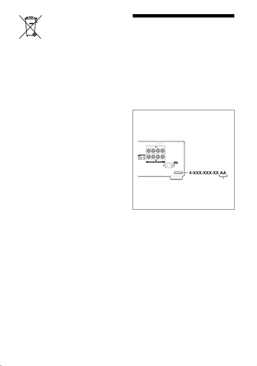
About area codes
The area code of the receiver you purchased is
shown on the lower right portion of the rear panel
(see the illustration below).
Area code
Any differences in operation, according to the area
code, are clearly indicated in the text, for example,
“Models of area code AA only”.
GB
3

Table of Contents
Description and location of parts...................5
Getting Started
1: Installing the speakers .............................12
2: Connecting the speakers..........................12
3a: Connecting the audio components.........13
3b: Connecting the video components ........14
4: Connecting the antennas (aerials)............18
5: Preparing the receiver and the remote.....18
6: Selecting the speaker system ...................20
Playback
Enjoying sound/images from the component
connected to the receiver........................21
Amplifier Operations
Navigating through menus...........................23
Adjusting the level (LEVEL menu)............. 25
Adjusting the equalizer (EQ menu) .............25
Settings for the tuner (TUNER menu).........26
Settings for the system (SYSTEM menu) ...26
Additional Information
Precautions.................................................. 41
Troubleshooting .......................................... 42
Specifications.............................................. 45
Index ........................................................... 47
Tuner Operations
Listening to FM/AM radio ..........................28
Presetting radio stations...............................29
Using the Radio Data System (RDS) ..........31
(Models of area code CEL, CEK only)
Other Operations
Enjoying the DIGITAL MEDIA PORT
(DMPORT).............................................33
Changing the display ...................................35
Using the Sleep Timer .................................36
Recording using the receiver .......................36
Using multi-zone features............................37
Using the Remote
Changing button assignments......................40
GB
4
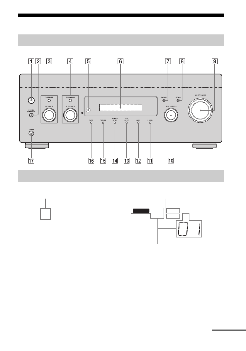
Description and location of parts
Front panel
About the indicators on the display
qk w;
SP A
SP B
MEMORY
ql
ZONE 2
RDS
MONO SLEEP
wa
ST
continued
GB
5
Name Function
A ?/1
(on/standby)
B SPEAKERS
(OFF/A/B/
A+B)
C TONE MODE Adjust the bass and treble
TONE +/–
D TUNING
MODE
TUNING +/–
E Remote
sensor
F Display
window
G DISPLAY Press repeatedly to select
H MUTING Press to turn off the sound
I MASTER
VOLUM E
J INPUT
SELECTOR
K DIMMER Press repeatedly to adjust the
L SLEEP Press to activate the sleep
M TONE ON/OFF Press to turn the bass and
N MEMORY/
ENTER
Press to turn the receiver on
or off (page 19).
Switch to OFF, A, B, A+B of
the front speakers (page 20).
level of the speakers. Press
TONE MODE repeatedly to
select bass or treble, then turn
TONE +/– to adjust the level
(page 24).
Press to operate a tuner
(FM/AM) (page 28).
Receives signals from remote
commander.
The current status of the
selected component or a list
of selectable items appears
here (page 5).
information displayed on the
display (page 35).
temporarily.
Press MUTING again to
restore the sound (page 21).
Turn to adjust the volume
level of all speakers at the
same time (page 21).
Turn to select the input
source to play back (page 21,
22, 35, 36, 37).
brightness of the display.
timer function and the
duration which the receiver
turns off automatically (page
36).
treble on or off.
Press to store a station or
enter the selection when
selecting the settings (page
19, 29).
Name Function
O FM MODE Press to select the FM
P FM/AM Press to select FM or AM
Q PHONES jack Connects to headphones
R SP A/SP B Lights up according to the
S SLEEP Lights up when the sleep
T ZONE 2 Lights up when operation in
U Tuning
indicators
MEMORY Lights up when a memory
RDS Lights up when a station that
MONO Monaural broadcast
ST Stereo broadcast
monaural or stereo reception
(page 28).
station.
(page 42).
speaker system used (page
20). However, these
indicators do not light up if
the speaker output is turned
off or if headphones are
connected.
timer is activated.
zone 2 is being enabled.
Lights up when the receiver
tunes in radio stations.
function, such as Preset
Memory (page 29), etc., is
activated.
provides RDS services is
tuned in.
Note
“RDS” appears for models of
area code CEL, CEK only.
A preset station number
appears when the preset radio
station is selected.
Note
The preset station number
will change accordingly to
the preset station you select.
For details on presetting
radio station, see page 29.
GB
6
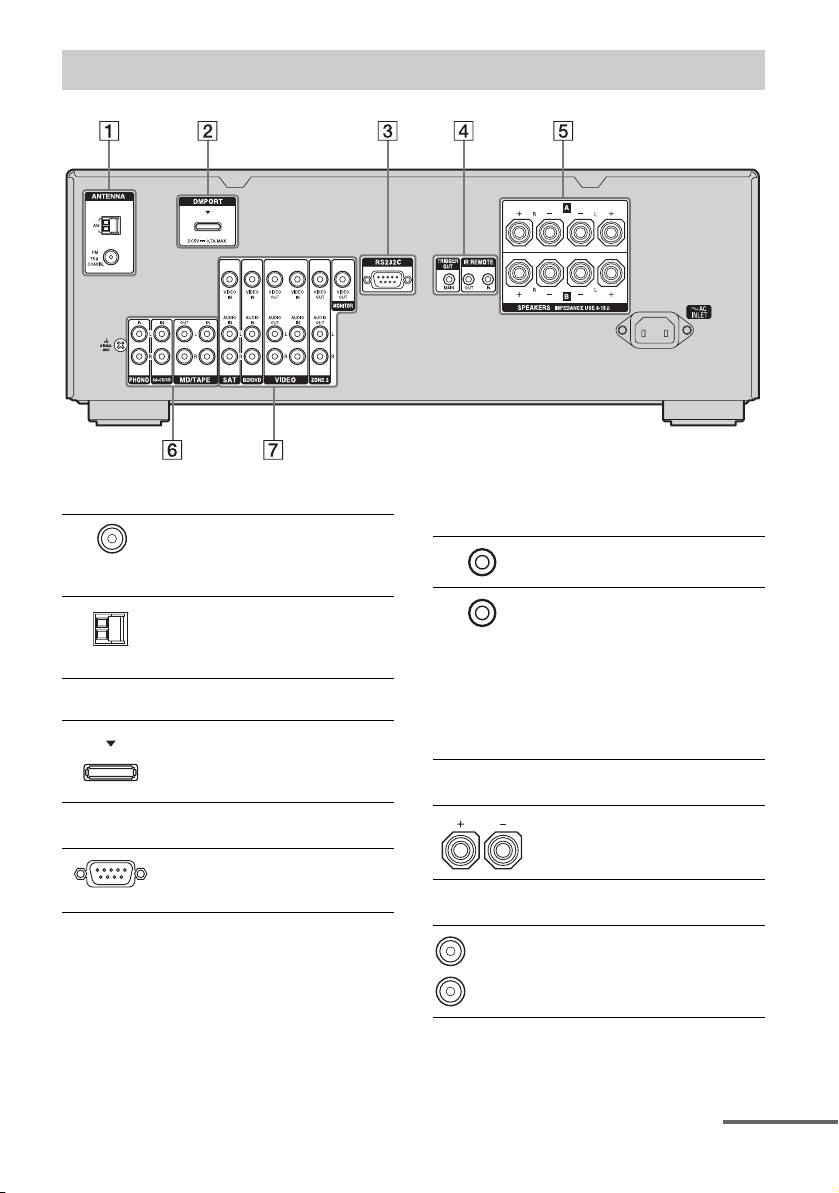
Rear panel
A ANTENNA section
FM
ANTENNA
jack
AM
ANTENNA
jack
B DMPORT
DMPORT
jack
C RS232C port
Connects to the
supplied FM wire
antenna (aerial)
(page 18).
Connects to the
supplied AM loop
antenna (aerial)
(page 18).
Connects to a
DIGITAL MEDIA
PORT adapter
(page 34).
Used for
maintenance and
service.
D Control jacks for Sony equipment
and other external components
IR REMOTE
IN/OUT jacks
TRIGGER
OUT jack
Connect an IR
repeater (page 37).
Connects to an
interlock on/off of
the power supply of
other 12V
TRIGGER
compliant
components, or the
amplifier/receiver
of zone 2 (page 26).
E SPEAKERS section
Connects to the
speakers (page 12).
F AUDIO INPUT/OUTPUT section
White (L)
Red (R)
AUDIO IN/
OUT jacks
Connects to a tape
deck or MD deck,
etc. (page 13).
continued
GB
7
G VIDEO/AUDIO INPUT/OUTPUT
section
White (L)
Red (R)
Yellow
* You can watch the selected input image when you
connect the MONITOR OUT jack to a TV (page
15–17).
AUDIO IN/
OUT jacks
VIDEO IN/
OUT* jacks
AUDIO OUT
jacks
VIDEO OUT
jack
Connects to a VCR,
DVD player, etc.
(page 15–17).
Connects to the
component in zone
2 (page 38).
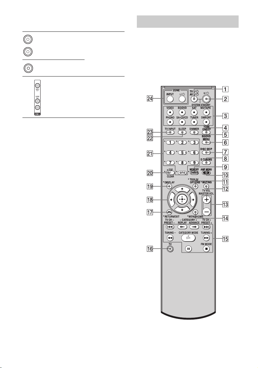
Remote commander
You can use the supplied RM-AAU056
Remote Commander to operate the receiver
and to control the Sony audio/video
components that the remote is assigned to
operate (page 40).
RM-AAU056
GB
8
Name Function
A TV ?/1
(on/standby)
AV ?/1
(on/standby)
B ?/1
(on/standby)
C Input buttons Press one of the buttons to
D TONE ON /OFF Press to turn the bass and
E DIMMER Press repeatedly to adjust the
F BD/DVD
MENU
Press TV ?/1 and TV (P) at
the same time to turn the TV
on or off.
Press to turn on or off the
Sony audio/video components
that the remote is assigned to
operate (page 40).
If you press ?/1 (B) at the
same time, it will turn off the
receiver and other Sony
components (SYSTEM
STANDBY).
Note
The function of the AV ?/1
switch changes automatically
each time you press the input
buttons (C).
Press to turn the receiver on or
off.
If zone 2 is selected, only the
main receiver is turned on or
off with this button. To turn
off all components including
an amplifier in zone 2, press
?/1 and AV ?/1 (A) at the
same time (SYSTEM
STANDBY).
Saving the power in standby
mode.
When “RS232C” (page 27) is
set to “OFF”.
select the component you
want to use. When you press
any of the input buttons, the
receiver turns on. The buttons
are factory assigned to control
Sony components.
You can change the button
assignments following the
steps in “Changing button
assignments” on page 40.
treble on or off.
brightness of the display.
Press to display the menu of
the DVD or Blu-ray disc on
the TV screen. Then, use V, v,
B, b and (qk) to perform
menu operations.
Name
Function
G DISC SKIP Press to skip a disc when
using a multi-disc changer.
H D.TUNING Press to enter direct tuning
mode.
I ENTER Press to enter the value after
selecting a channel, disc or
track using the numeric
buttons of the TV, VCR, CD
player, DVD player, DVD
recorder or satellite tuner.
MEMORY Press to store a station during
tuner operation.
J AMP MENU Press to display the menu of
the receiver. Then, use V, v,
B, b and (qk) to perform
menu operations.
K TOOLS/
OPTIONS
Press to display and select the
options of the DVD player or
Blu-ray disc player.
Press TOOLS/OPTIONS and
TV (P) at the same time to
display the options applicable
to the Sony TV.
L MUTING Press to turn off the sound
temporarily.
Press MUTING again to
restore the sound.
Press MUTING and TV (P)
at the same time to activate
the TV’s muting function.
M TV VOL
a)
+
/–
Press TV VOL +/– and TV
(P) at the same time to adjust
the volume level of the TV.
MASTER
a)
VOL +
Press to adjust the volume
/–
level of all speakers at the
same time.
N MENU/HOME Press to display the menu of
the VCR, DVD player,
satellite tuner or Blu-ray disc
player on the TV screen.
Press MENU/HOME and TV
(P) at the same time to
display the TV’s menu.
Then, use V, v, B, b and
(qk) to perform menu
operations.
continued
GB
9
Name
O ./>
Function
b)
Press to skip a track of the CD
player, DVD player, DVD
recorder, MD deck, tape deck
or Blu-ray disc player.
REPLAY /
ADVANCE
<
Press to replay the previous
<
scene or fast forward the
current scene of the VCR,
DVD player or Blu-ray disc
player.
b)
m/M
Press to
– search tracks in the forward/
reverse direction of the
DVD player.
– start fast forward/rewind of
the VCR, CD player, DVD
recorder, MD deck, tape
deck or Blu-ray disc player.
a)b)
H
Press to start playback of the
VCR, CD player, DVD
player, DVD recorder, MD
deck or Blu-ray disc player.
b)
X
Press to pause playback or
recording of the VCR, CD
player, DVD player, DVD
recorder, MD deck, tape deck
or Blu-ray disc player. (Also
starts recording with
components in recording
standby.)
b)
x
Press to stop playback of the
VCR, CD player, DVD
player, DVD recorder, MD
deck, tape deck or Blu-ray
disc player.
TV CH +/– Press TV CH +/– and TV (P)
at the same time to select
preset TV channels.
PRESET +/– Press to select
– preset stations.
– preset channels of the VCR
or satellite tuner.
TUNING +/– Press to scan a station.
FM MODE Press to select the FM
monaural or stereo reception.
P TV Press TV and the button with
orange printing at the same
time to enable TV operation.
GB
10
Name Function
Q RETURN/
EXIT O
R
V/v/B/b
S DISPLAY Press to select information
T -/-- Press to select the channel
>10/
-
CLEAR Press to clear a mistake when
Press to
– return to the previous menu.
– exit the menu while the
menu or on-screen guide of
the DVD recorder, DVD
player, satellite tuner or Bluray disc player is displayed
on the TV screen.
Press RETURN/EXIT O
and TV (P) at the same time
to return to the previous menu
or exit the TV’s menu while
the menu is displayed on the
TV screen.
After pressing BD/DVD
MENU (F), AMP MENU
(0), or MENU/HOME (N),
press V, v, B or b to select the
settings. Then, press to
enter the selection if you have
pressed BD/DVD MENU or
MENU/HOME previously.
Press also to enter the
selection of the receiver,
VCR, satellite tuner, CD
player, DVD player, DVD
recorder or Blu-ray disc
player.
displayed on the TV screen of
the VCR, satellite tuner, CD
player, DVD player, DVD
recorder, MD deck or Blu-ray
disc player.
Press DISPLAY and TV (P)
at the same time to display
TV’s information on the TV
screen.
entry mode, either one or two
digit of the VCR, satellite
tuner, etc.
Press -/-- and TV (P) at the
same time to select the
channel entry mode, either
one or two digits of the TV.
Press to select
– track numbers over 10 of the
VCR, satellite tuner, MD
deck or CD player.
– channel numbers of the
Digital CATV terminal.
you press the incorrect
numeric button.

Name Function
U Numeric
buttons
(number 5
V SLEEP Press to activate the Sleep
W TV INPUT Press TV INPUT and TV (P)
X ZONE ?/1 Press ZONE ?/1 to turn the
ZONE INPUT Press ZONE INPUT
a)
The nu mb er 5, MASTER VOL +, TV VOL + , and
H buttons have tactile dots. Use the tactile dots
as references when operating the receiver.
b)
This button is also available for DIGITAL MEDIA
PORT adapter operation. For details on the
function of the button, refer to the operating
instructions supplied with the DIGITAL MEDIA
PORT adapter.
Press to
– preset/tune to preset
a)
)
stations.
– select track numbers of the
CD player, DVD player,
DVD recorder, MD deck or
Blu-ray disc player. Press
0/10 to select track number
10.
– select channel numbers of
the VCR or satellite tuner.
Press the numeric buttons and
TV (P) at the same time to
select the TV channels.
Timer function and the
duration which the receiver
turns off automatically.
at the same time to select the
input signal (TV input or
video input).
zone 2 on or off.
repeatedly to select the input
source for zone 2.
Notes
• Some functions explained in this section may not
work depending on the model.
• The above explanation is intended to serve as an
example only. Therefore, depending on the
component, the above operation may not be
possible or may operate differently than described.
• The CATEGORY +/– and CATEGORY MODE
buttons are not applicable for models of area code
CEL and CEK.
11
GB
Getting Started
1: Installing the speakers
This receiver allows you to use a 2.0 channel
system.
Example of the speaker system
configuration
Right speakerLeft speaker
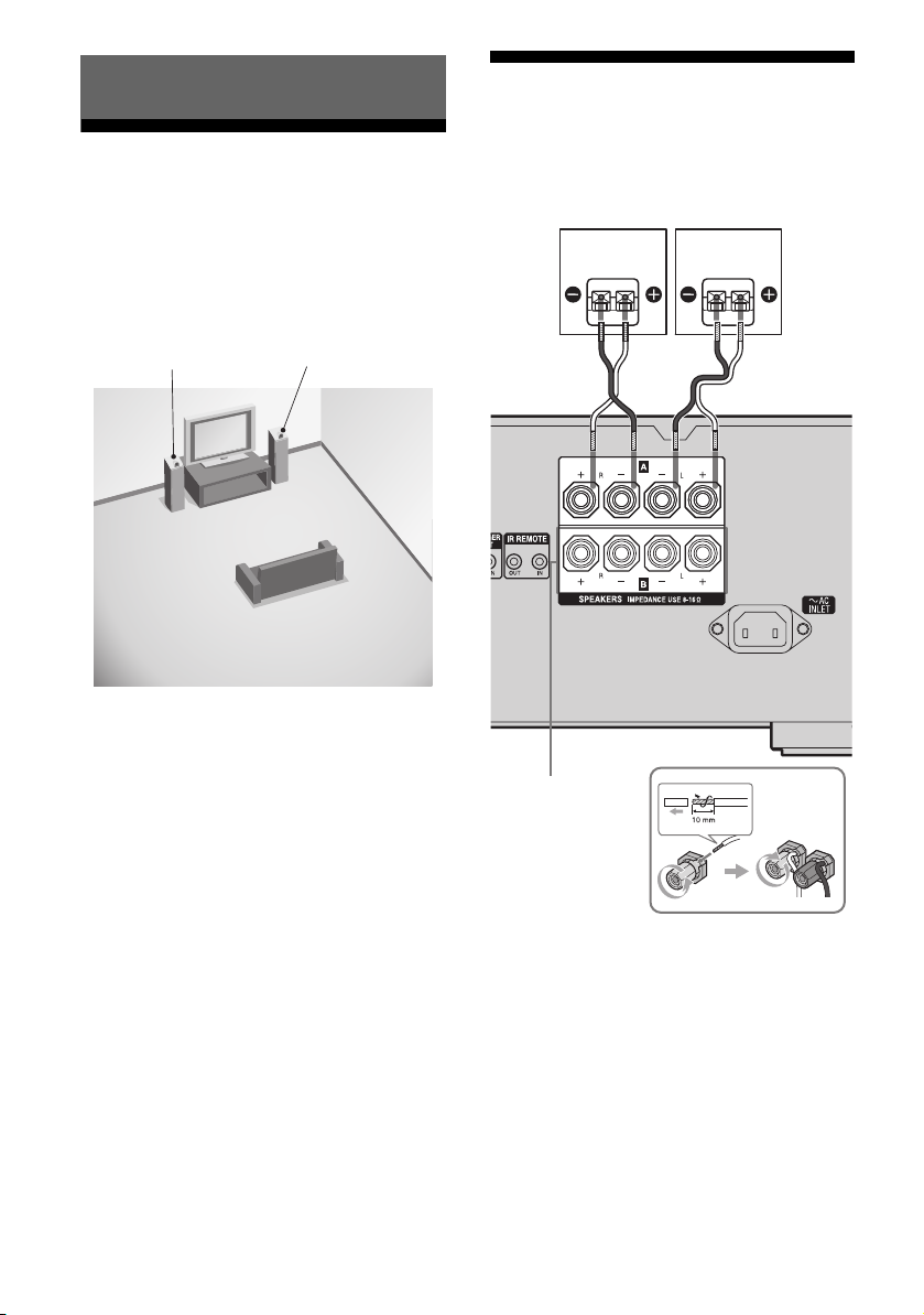
2: Connecting the speakers
Before connecting the cords, be sure to
disconnect the AC power cord (mains lead).
Left speakerRight speaker
A
12
SPEAKERS B
terminals*
A Speaker cords (not supplied)
*
If you have an additional front speaker system,
connect them to the SPEAKERS B terminals.
You can select the front speakers you want to use
with SPEAKERS (OFF/A/B/A+B) on the front
panel (page 20).
GB
.
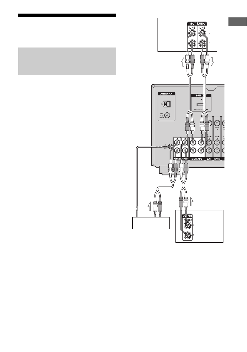
3a: Connecting the audio components
Connecting a Super Audio CD
player, CD player, MD deck,
Tape deck or Turntable
The following illustration shows how to
connect a Super Audio CD player, CD player,
MD deck, tape deck or turntable.
Before connecting the cords, be sure to
disconnect the AC power cord (mains lead).
After connecting your audio component,
proceed to “3b: Connecting the video
components”(page 14).
MD deck,
Tape deck
A
Getting Started
A
Super Audio
Turntable
CD player,
CD player
A Audio cord (not supplied)
Note
If your turntable has a ground (earth) wire, connect
it to the (U) SIGNAL GND terminal.
13
GB

3b: Connecting the video components
How to connect your
components
This section describes how to connect your
video components to this receiver. Before you
begin, refer to “Component to be connected”
below for the pages which describe how to
connect each component.
Before connecting the cords, be sure to
disconnect the AC power cord (mains lead).
After connecting all your components,
proceed to “4: Connecting the antennas
(aerials)” (page 18).
Component to be connected Page
Blu-ray disc player, DVD player 15
Satellite tuner, Set-top box 16
DVD recorder, VCR 17
14
GB
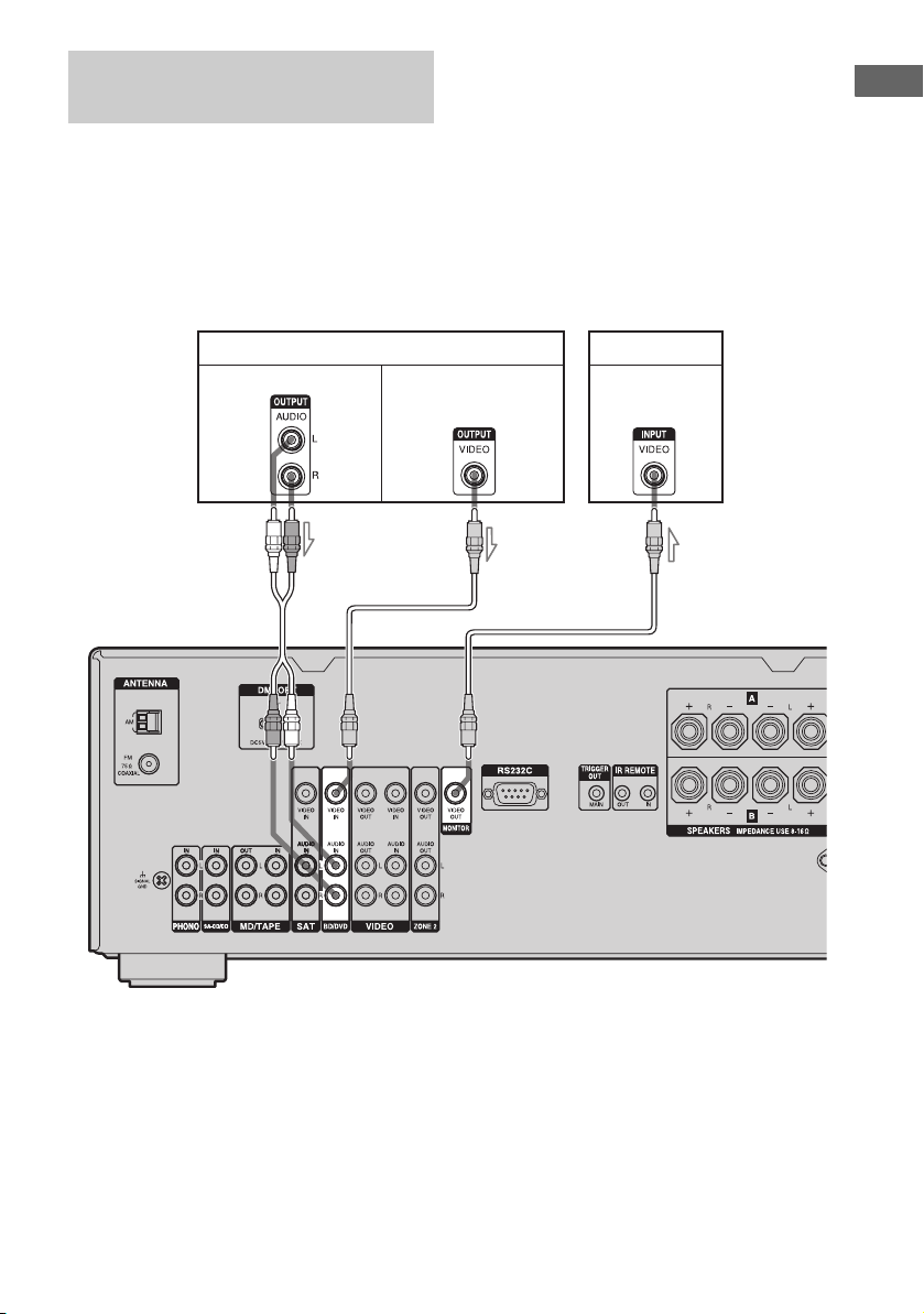
Connecting a Blu-ray disc
player, DVD player
The following illustration shows how to
connect a Blu-ray disc player or a DVD player.
Connect audio and video cords according to
the jacks of your components.
If you connect a DVD player
• Be sure to change the factory setting of the
BD/DVD input button on the remote so that
you can use the button to control your DVD
player. For details, see “Changing button
assignments” (page 40).
• You can also rename the BD/DVD input so
that it can be displayed on the receiver’s
display. For details, see “Naming inputs”
(page 22).
Getting Started
Blu-ray disc player, DVD player
Audio signals Video signals
AB
TV
Video signals
B
A Audio cord (not supplied)
B Video cord (not supplied)
15
GB
 Loading...