

Page 1
2-694-840-12(2)
Multi Channel
AV Receiver
Operating Instructions
STR-DA1200ES
©2006 Sony CorporationSony Corporation Printed in Malaysia
Page 2
WARNING
To reduce the risk of fire or electric
shock, do not expose this apparatus to
rain or moisture.
To prevent fire, do not cover the ventilation of the
apparatus with news papers, table-cloths, curtains,
etc. And don’t place lighted candles on the
apparatus.
To prevent fire or shock hazard, do not place objects
filled with liquids, such as vases, on the apparatus.
Do not install the appliance in a confined space, such
as a bookcase or built-in cabinet.
Install this system so that the power cord can be
unplugged from the wall socket immediately in the
event of trouble.
Don’t throw away the battery with
general house waste, dispose of it
correctly as chemical waste.
NOTICE FOR THE CUSTOMERS IN THE
UNITED KINGDOM
A moulded plug complying with BS1363 is fitted to
this equipment for your safety and convenience.
Should the fuse in the plug supplied need to be
replaced, a fuse of the same rating as the supplied
one and approved by ASTA or BSI to BS1362, (i.e.,
marked with or mark) must be used.
If the plug supplied with this equipment has a
detachable fuse cover, be sure to attach the fuse
cover after you change the fuse. Never use the plug
without the fuse cover.
If you should lose the fuse cover, please contact your
nearest Sony service station.
For customers in Europe
Disposal of Old Electrical & Electronic
Equipment (Applicable in the European
Union and other European countries
with separate collection systems)
This symbol on the product or on its
packaging indicates that this product
shall not be treated as househ old waste.
Instead it shall be handed over to the
applicable collection point for the
recycling of electrical and electronic
equipment. By ensuring this product is
disposed of correctly, you will help
prevent potential negative
consequences for the environment and
human health, which could otherwise
be caused by inappropriate waste
handling of this product. The recycling
of materials will help to conserve
natural resources. For more detailed
information about recycling of this
product, please contact your local
Civic Office, your household waste
disposal service or the shop where you
purchased the product.
GB
2
Page 3

About This Manual
• The instructions in this manual are for model STRDA1200ES. Check your mod el number by looking
at the lower right corner of the front panel.
• The instructions in this manual describe the
controls on the supplied remote. You can also use
the controls on the receiver if they have the same
or similar names as those on the remote.
This receiver incorporates Dolby* Digital and Pro
Logic Surround and the DTS** Digital Surround
System.
* Manufactured under license from Dolby
Laboratories.
“Dolby”, “Pro Logic”, “Surround EX”, and the
double-D symbol are trademarks of Dolby
Laboratories.
** Manufactured under license from Digital
Theater Systems, Inc. U.S. Pat.
No’s. 5,451,942; 5,956,674; 5,974,380;
5,978,762; 6,226,616; 6,487,535 and other U.S.
and world-wide patents issued and pending.
“DTS”, “DTS-ES”, “Neo:6”, and “DTS 96/24”
are trademarks of Digital Theater Systems, Inc.
Copyright 1996, 2003 Digital Theater Systems,
Inc. All Rights Reserved.
This receiver incorporates High-Definition
Multimedia Interface (HDMI™) technology.
HDMI, the HDMI logo and High-Definition
Multimedia Interface are trademarks or registered
trademarks of HDMI Licensing LLC.
GB
3
Page 4

Table of Contents
Getting Started
Description and location of parts ..................6
1: Installing speakers ..................................16
2: Connecting speakers ...............................17
3a: Connecting the audio components ........19
3b: Connecting the video components .......24
4: Connecting the antennas (aerials) ...........35
5: Preparing the receiver and the remote ....36
6: Setting the speakers ................................38
7: Calibrating the appropriate settings
automatically
(AUTO CALIBRATION) ......................40
Playback
Selecting a component ................................47
Listening to a Super Audio CD/CD ............48
Watching a DVD .........................................49
Enjoying video games ................................50
Watching video ...........................................51
Amplifier Operations
Navigating through menus ..........................52
Adjusting the level
(Level Settings menu) ............................56
Adjusting the equalizer
(EQ Settings menu) ...............................57
Settings for the surround sound
(Sur Settings menu) ...............................59
Settings for the tuner
(Tuner Settings menu) ...........................61
Settings for the audio
(Audio Settings menu) ...........................62
Settings for the video
(Video Settings menu) ...........................63
Settings for the speakers
(Speaker Settings menu) ........................63
Settings for the system
(System Settings menu) .........................67
Calibrating the appropriate settings
automatically
(Auto Calibration menu) ....................... 68
Enjoying Surround Sound
Enjoying Dolby Digital and DTS surround
sound (A.F.D. mode) ............................. 69
Selecting a pre-programmed sound field
(DCS) .................................................... 71
Using only the front speakers
(2CH STEREO) .................................... 73
Enjoying the surround effect at low volume
levels (NIGHT MODE) ........................ 73
Listening to the sound without any adjustment
(ANALOG DIRECT) ............................ 74
Adjusting the speaker levels and balance
(TEST TONE) ....................................... 74
Resetting sound fields
to the initial settings .............................. 76
Tuner Operations
Listening to FM/AM radio ......................... 77
Storing FM stations automatically
(AUTOBETICAL) ................................ 78
Presetting radio stations ............................. 79
Using the Radio Data System (RDS) ......... 81
Other Operations
Displaying menus of the receiver on the TV
screen .................................................... 83
Naming inputs ............................................ 84
Switching between digital and analog audio
(INPUT MODE) ................................... 85
Listening to digital sound from other inputs
(DIGITAL ASSIGN) ............................ 86
Watching HDMI images from other inputs
(HDMI ASSIGN) .................................. 87
GB
4
Page 5

Watching component images from other
inputs
(COMPONENT VIDEO ASSIGN) ...... 88
Changing the display .................................. 89
Using the Sleep Timer ................................ 90
Recording using the receiver ...................... 90
Using a bi-amplifier connection ................. 91
Using the Remote
Operating each component
using the remote .................................... 93
Programming the remote ............................ 94
Clearing all the contents of the remote’s
memory ................................................. 97
Additional Information
Glossary .....................................................98
Precautions ...............................................100
Troubleshooting ....................................... 101
Specifications ...........................................105
Index .........................................................108
GB
5
Page 6
Getting Started
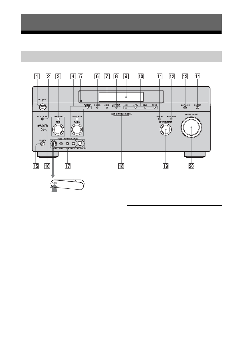
Description and location of parts
Front panel
To remove the cover
Press PUSH.
When you remove the cover, keep it out of
reach from children.
GB
6
Name Function
A POWER Press to turn the
receiver on or off (page
36, 48, 49, 50, 51, 76).
B AUTO CAL MIC
jack
Connects to the
supplied optimizer
microphone for the
Digital Cinema Auto
Calibration function
(page 40).
Page 7

Name Function
C TONE MODE Adjusts FRONT BASS
TONE
and FRONT TREBLE.
Press TONE MODE
repeatedly to select
BASS or TREBLE,
then turn TONE to
adjust the level (page
57).
D MEMORY/
ENTER
Press to operate a tuner
(FM/AM) (page 77).
TUNING MODE
TUNING
E Remote sensor Receives signals from
remote commander.
F DIMMER Press to adjust
brightness of the
display.
G SLEEP Press to activate the
SLEEP function (page
90).
H SUR BACK
DECODING
Press to activate SB
DECODING (page
60).
I Display
window
The current status of
the selected component
or a list of selectable
items appears here
(page 8).
J 2CH Press to select sound
A.F.D.
field (page 69).
MOVIE
MUSIC
K DISPLAY Press to select
information displayed
on the display window
(page 89).
Name Function
L INPUT MODE Press to select the input
mode when the same
components are
connected to both
digital and analog jacks
(page 85).
M MULTI CH IN Press to select the audio
input signal from the
component connected
to the MULTI
CHANNEL INPUT
jack (page 47).
N A.DIRECT Press to listen to high
quality analog sound
(page 74).
O PHONES jack Connects to
headphones (page 72).
P SPEAKERS
(OFF/A/B/A+B)
Press to select A, B,
A+B, OFF of the front
speakers (page 38).
Q VIDEO 3 IN/
PORTABLE AV
IN jack
Connect to a portable
audio/video c omponent
such as a camcorder or
video game (page 32,
50).
R MULTI
CHANNEL
DECODING
Lights up when multichannel audio signals
are decoded (page 49).
lamp
S INPUT
SELECTOR
Turn to select the input
source to play back
(page 47, 48, 49, 50,
51, 84, 85, 91).
T MASTER
VOLUME
Turn to adjust the
volume level of all
speakers at the same
time (page 47, 48, 49,
50, 51).
Getting Started
GB
7
Page 8
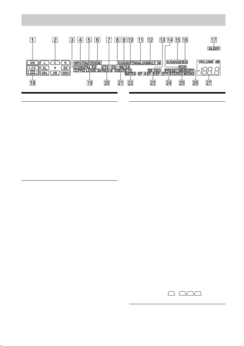
About the indicators on the display
Name Function
A SW Lights up when sub woofer
selection is set to “YES”
and the audio signal is
output from the SUB
WOOFER jack (page 63).
While this indicator lights
up, the receiver creates a
sub woofer signal based on
the L.F.E. signal in the disc
being played back or the
low frequency components
of the front channels.
Name Function
B Playback
channel
indicators
The letters (L, C, R, etc.)
indicate the channels being
played back. The boxes
around the letters vary to
show how the receiver
downmixes the source
sound (based on the speaker
settings).
L
R
C
SL
SR
S
Front Left
Front Right
Center (monaural)
Surround Left
Surround Right
Surround (monaural or the
surround components
obtained by Pro Logic
processing)
SBL
SBR
SB
Surround Back Left
Surround Back Right
Surround Back (the
surround back components
obtained by 6.1 channel
decoding)
Example:
Recording format (Front/
Surround): 3/2.1
Output channel: Surround
speakers are set to “NO.”
Sound Field: A.F.D. AUTO
LSW
SL
CR
SR
GB
8
Page 9

Name Function
C ;DIGITAL
(EX)
Lights up when the receiver
is decoding Dolby Digital
Surround signals.
“;DIGITAL EX” also
lights up when the receiver
is decoding Dolby Digital
Surround EX signals. When
playing a Dolby Digital
format disc, be sure that you
have made digital
connections and that
INPUT MODE is not set to
“ANALOG” (page 85).
D INPUT Lights up constantly. One of
the input indicators also
lights up according to the
current input.
E AUTO Lights up when INPUT
MODE is set to “AUTO”
(page 85).
F HDMI Lights up when the receiver
recognizes a component
connected via an HDMI IN
jack (page 25).
G DTS (-ES) Lights up when the receiver
is decoding DTS signals.
“DTS-ES” also lights up
when the receiver is
decoding DTS-ES signals.
When playing a DTS
format disc, be sure that you
have made digital
connections and that
INPUT MODE is not set to
“ANALOG” (page 85).
H 96/24 Lights up when the receiver
is decoding DTS96/24 (96
kHz/24 bit).
Name Function
I COAX Lights up when INPUT
MODE is set to “AUTO”
and the source signal is a
digital signal being input
through the COAXIAL
jack, or when INPUT
MODE is set to “COAX”
(page 85).
J OPT Lights up when INPUT
MODE is set to “AUTO”
and the source signal is a
digital signal being input
through the OPTICAL jack,
or when INPUT MODE is
set to “OPT” (page 85).
K ANALOG Lights up when INPUT
MODE is set to “AUTO”
and no digital signal is
being input through the
COAXIAL or OPTICAL
jacks, or when INPUT
MODE is set to
“ANALOG,” or when the
ANALOG DIRECT
function is being used (page
85).
L MULTI IN Lights up when MULTI IN
is selected (page 47).
M SB DEC Lights up when surround
back sound decoding is
activated (page 60).
N RDS Lights up while receiving
RDS information (page 81).
O D.RANGE Lights up when dynamic
range compression is
activated (page 57).
P EQ Lights up when the
equalizer is activated (page
57).
Q SLEEP Lights up when the sleep
timer is activated (page 90).
Getting Started
continued
GB
9
Page 10

Name Function
R L.F.E. Lights up when the disc
being played back contains
an L.F.E. (Low Frequency
Effect) channel and the
L.F.E. channel signal is
actually being reproduced,
the bars underneath the
letters light up to indicate
the level. Since the L.F.E.
signal is not recorded in all
parts of the input signal the
bar indication will fluctuate
(and may turn off) during
playback.
S ;PRO
LOGIC (II/
IIx)
Lights up when the receiver
applies Pro Logic
processing to 2 channel
signals in order to output
the center and surround
channel signals. “;PRO
LOGIC II” also lights up
when the Pro Logic II
MOVIE/MUSIC/GAME
decoder is activated.
“;PRO LOGIC IIx” also
lights up when the Pro
Logic IIx MOVIE/MUSIC/
GAME decoder is activated
(page 70).
Note
This indicator does not light if
both the center and surround
speakers are set to “NO” (page
64).
T NEO:6 Lights up when DTS Neo:6
Cinema/Music decoding is
activated (page 70).
U DISCRETE Lights up when DTS-ES
Discrete decoding is
activated (page 60).
V MATRIX Lights up when DTS-ES
Matrix decoding is
activated (page 60).
Name Function
W SP-A/SP-B/
SP-OFF
Lights up according to the
speaker system used (page
38).
“SP-OFF” lights up when
“SP-OFF” is selected or
headphones are connected.
X PRESET Lights up when TUNING
MODE is “PRESET.”
Y Tuner
indicators
Lights up when using the
receiver to tune in radio
stations (page 77–82), etc.
Z MEMORY Lights up when a memory
function, such as Name
Input (page 84) etc., is
activated.
wj VOLUME Displays the current
volume.
10
GB
Page 11
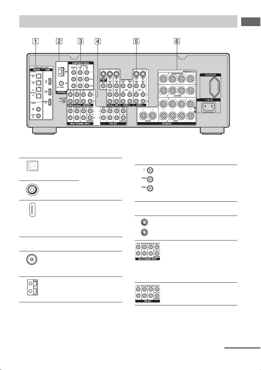
Rear panel
Getting Started
A DIGITAL INPUT/OUTPUT section
OPTICAL IN/
OUT jacks
COAXIAL IN
jacks
HDMI IN/
MONITOR
OUT jacks
Connects to a DVD
player, Super Audio
CD player, etc. The
COAXIAL jack
provides a better
quality sound (page
19, 20, 29).
Connects to a DVD
player, or a satellite
tuner. An image and
the sound are output
to TV or a projector
(page 25).
B ANTENNA section
FM ANTENNA
jack
AM
ANTENNA
jack
Connects to the FM
wire antenna (aerial)
supplied with this
receiver (page 35).
Connects to the AM
loop antenna (aerial)
supplied with this
receiver (page 35).
C COMPONENT VIDEO INPUT/
OUTPUT section
COMPONENT
VIDEO (Y, P
, PR/CR)
C
B
INPUT/
OUTPUT
jacks*
Connects to a DVD
/
player, TV, or a
B
satellite tuner. (page
27, 29).
D AUDIO INPUT/OUTPUT section
AUD IO I N/
L
OUT jacks
R
MULTI
CHANNEL
INPUT jacks
PRE OUT jacks Connects to an
Connects to a MD
deck or tape deck,
etc (page 19, 23).
Connects to a Super
Audio CD player or
DVD player with an
analog audio jack for
7.1 channel or 5.1
channel sound (page
19, 22).
external power
amplifier.
continued
11
GB
Page 12
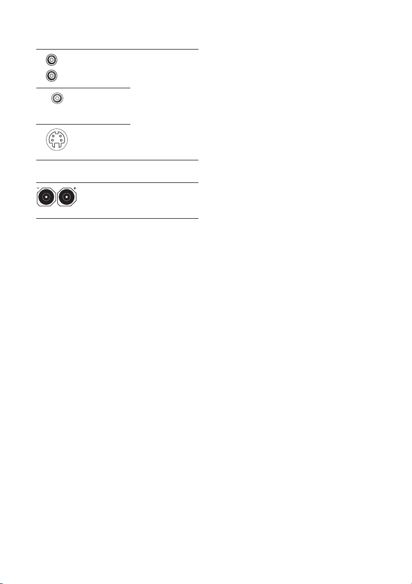
E VIDEO/AUDIO INPUT/OUTPUT
section
L
R
AUD IO I N/
OUT jacks
VIDEO IN/
OUT jacks*
S VIDEO IN/
OUT jacks*
Connects to a VCR
or a DVD player etc.
(page 29, 30, 31, 32).
F SPEAKERS section
Connects to speakers
(page 17).
* You can watch the selected input image when you
connect the MONITOR OUT jack to a TV (page
27). You can also display c ertain menu settings and
the sound field on the monitor when you press ON
SCREEN on the remote (page 83).
12
GB
Page 13
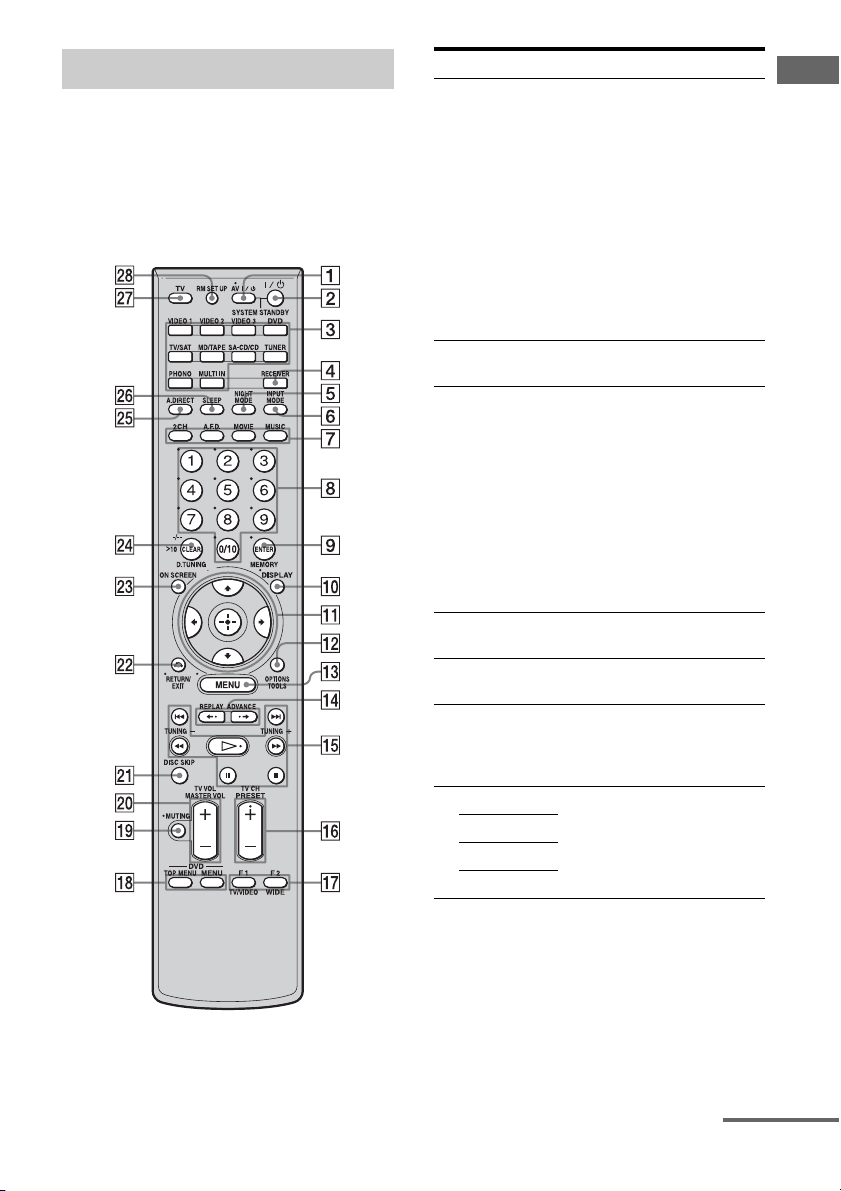
Remote commander
You can use the supplied remote RM-AAP015
to operate the receiver and to control the Sony
audio/video components that the remote is
assigned to operate (page 94).
RM-AAP015
Name Function
A AV ?/1
(on/standby)
B ?/1
(on/standby)
C Input
buttons
D RECEIVER Press to enable the receiver
E NIGHT
MODE
F INPUT
MODE
G 2CH Press to select a sound field
A.F.D.
MOVIE
MUSIC
Press to turn on or off the audio/
video components that the
remote is assigned to operate
(page 94).
If you press the ?/1 (B) at the
same time, it will turn off the
receiver and other Sony
components (SYSTEM
STANDBY).
Note
The function of the AV ?/1
switch changes automatically
each time you press the input
button (C).
Press to turn the receiver on or
off.
Press one of the buttons to
select the component you want
to use. When you press any of
the input buttons, the receiver
turns on. The buttons are
factory assigned to control Sony
components (page 47). You can
program the remote to control
non-Sony components
following the steps in
“Programming the remote”
(page 94).
operation (page 52).
Press to activate the NIGHT
MODE function (page 73).
Press to select the input mode
when the same components are
connected to both digital and
analog jacks (page 85).
(page 69).
Getting Started
continued
13
GB
Page 14
Name Function
H Numeric
buttons
I ENTER Press to enter the value after
MEMORY Press to store a tuner station
J DISPLAY Press to select information
K After pressing MENU (qd) or
V/v/B/b
L TOOLS Press to display and select items
OPTIONS
M MENU Press to display the menu of the
N REPLAY B·/
ADVANCE
·
b
O m/M
a)
x
a)
X
b)
H
./>
TUNING +/– Press to select stations (page 77,
P PRESET
b)
/–
+
TV CH +/– Press TV (wj) and then press
Press to
– preset/tune to preset stations.
– select track numbers of the
CD player, DVD player or
MD deck. Press 0/10 to
select track number 10.
– select channel numbers of
the VCR or satellite tuner.
– After pressing TV (wj),
press the numeric buttons to
select the TV channels.
selecting a channel, disc or
track using the numeric buttons.
during tuner operation.
displayed on the display
window, TV screen of the VCR,
satellite tuner, CD player, DVD
player, or MD deck (page 89).
TOP MENU (qk), press V/v, B
or b to select the settings. Then
press to enter the selection
(page 52).
from the option menus for DVD
player, etc.
receiver, a DVD player or TV,
etc.
Press to replay the previous
scene or fast forward the current
scene of the VCR or DVD
player.
a)
Press to operate the DVD
player, CD player, MD deck or
tape deck, etc.
a)
80).
Press to register FM/AM Radio
stations or to select preset
stations.
TV CH+/– to operate the TV,
satellite tuner, VCR, etc.
Name Function
Q F1/F2 Press TV (wj) and then press
TV/VIDEO Press TV/VIDEO and TV (wj)
WIDE Press to select the wide picture
R TOP M ENU Press to display the menu or
MENU Press to display the menus of
S MUTING Press to activate the muting
T MASTER
VOL +/–
TV VOL +/– Press TV (wj) and then press
U DISC SKIP Press to skip a disc when using
V RETURN/
EXIT O
W ON SCREEN Press to display the receiver
F1 or F2 to select a component
to operate.
• Hard disk recorder
F1: HDD
F2: DVD
• DVD/VHS combo player
F1: DVD
F2: VHS
at the same time to select the
input signal (TV input or video
input).
mode.
on-screen guide of the DVD
player on the TV screen. Then
use V/v/B/b and to perform
menu operations.
the DVD player on the TV
screen. Then use V /v/B/b and
to perform menu operations
(page 93).
function (page 47).
Press to adjust the volume level
of all speakers at the same time
(page 47).
TV VOL +/– to adjust the
volume level of the TV.
a multi-disc changer.
Press to return to the previous
menu or exit the menu while the
menu or on-screen guide of the
VCR, DVD player, or satellite
tuner is displayed on the TV
screen (page 93).
status. Then, if you press
MENU (qd), the menus of the
receiver appear (page 83).
14
GB
Page 15

Name Function
X CLEAR Press to
>10 Press to select
D.TUNING Press to enter direct tuning
Y A.DIRECT Press to switch the audio of the
Z SLEEP Press to activate the Sleep
wj TV Press to enable TV operation.
wk RM SET UP Press to set up the remote.
a)
See the table on page 93 for information on the
buttons that you can use to control each
component.
b)
The tactile dot is attached to these buttons (H,
PRESET+). Use as a mark of operation.
– clear a mistake when you
press the incorrect numeric
button.
– return to continuous
playback, etc. of the satellite
tuner or DVD player.
– track numbers over 10 of the
VCR, satellite tuner, CD
player or MD deck.
– channel numbers of the
Digital CATV terminal.
mode (page 78).
selected input to analog signal
without any adjustment (page
74).
Timer function and the duration
which the receiver turns off
automatically (page 90).
Notes
• Some functions explained in this section may not
work depending on the model.
• The above explanation is intended to serve as an
example only. Therefore, depending on the
component, the above operation may not be
possible or may operate differently than described.
Getting Started
15
GB
Page 16
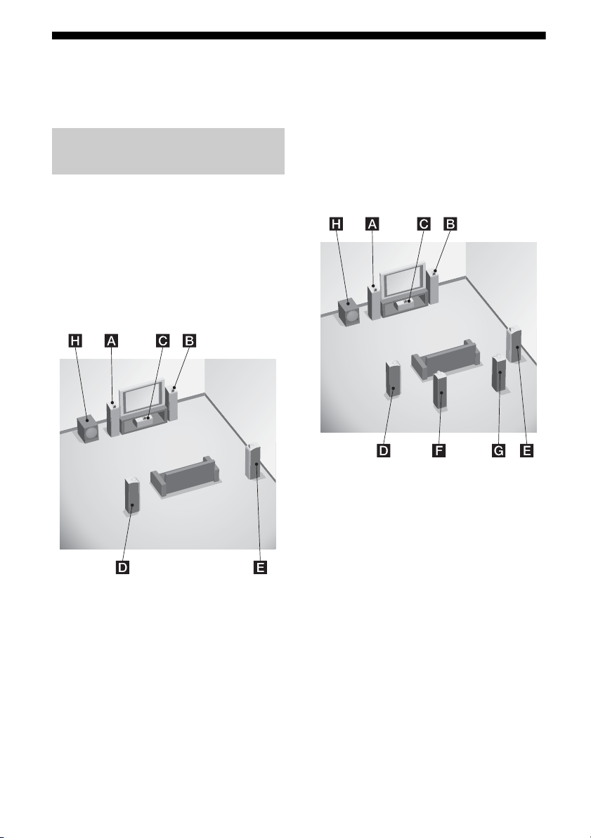
1: Installing speakers
This receiver allows you to use a 7.1 channel
system (7 speakers and one sub woofer).
Enjoying a 5.1/7.1 channel
system
To fully enjoy theater-like multi-channel
surround sound requires five speakers (two
front speakers, a center speaker, and two
surround speakers) and a sub woofer (5.1
channel system).
Example of a 5.1 channel
speaker system configuration
AFront left speaker
BFront right speaker
CCenter speaker
DSurround left speaker
ESurround right speaker
HSub woofer
You can enjoy high fidelity reproduction of
DVD software recorded sound in the Surround
EX format if you connect one additional
surround back speaker (6.1 channel system) or
two surround back speakers (7.1 channel
system). (see “Using the surround back
decoding mode (SB DECODING)” on page
60).
Example of a 7.1 channel
speaker system configuration
AFront left speaker
BFront right speaker
CCenter speaker
DSurround left speaker
ESurround right speaker
FSurround back left speaker
GSurround back right speaker
HSub woofer
Tips
• When you connect a 6.1 channel speaker system,
place the surround back speaker behind the
listening position.
• Since the sub woofer does not emit highly
directional signals, you can place it wherever you
want.
16
GB
Page 17
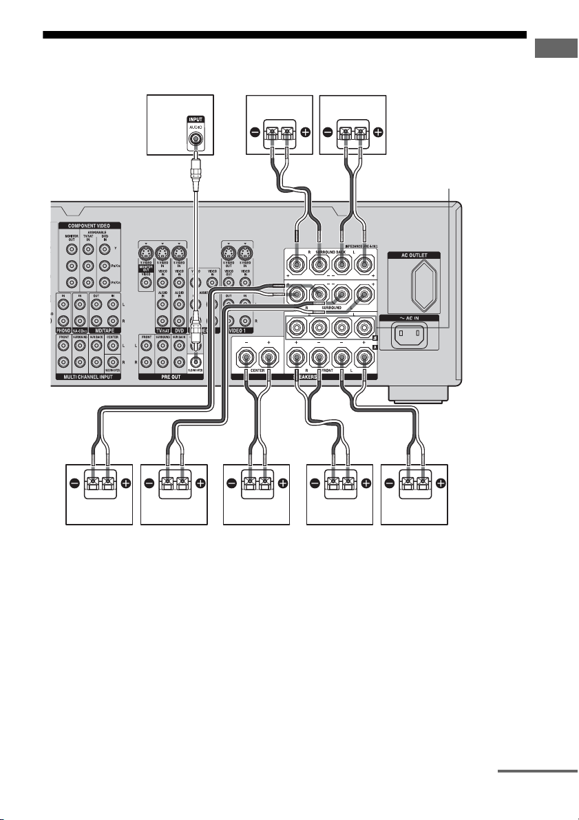
2: Connecting speakers
HGF
Getting Started
AB
A Monaural audio cord (not supplied)
B Speaker cords (not supplied)
BADEC
FRONT SPEAKERS
B terminals
a)
AFront speaker A (L)
BFront speaker A (R)
CCenter speaker
DSurround speaker (L)
ESurround speaker (R)
FSurround back speaker (L)
GSurround back speaker (R)
HSub woofer
c)
a)
If you have an additional front speaker
system, connect them to the FRONT
SPEAKERS B terminals. You can select
the front speaker system you want to use
with the SPEAKERS (OFF/A/B/A+B) on
b)
b)
the front panel (page 38).
b)
If you connect only one surround back
speaker, connect it to the SURROUND
BACK SPEAKERS L terminals.
continued
17
GB
Page 18

c)
When you connect a sub woofer with an auto
standby function, turn off the function when
watching movies. If the auto standby
function is set to on, it turns to standby mode
automatically based on the level of the input
signal to a sub woofer, then sound may not
be output.
Note
When you connect all the speakers with a nominal
impedance of 8 ohms or higher, set
“SP. IMPEDANCE” in the System Settings menu to
“8 ohm.” In other connections, set it to “4 ohm.” For
details, see “6: Setting the speakers” (page 38).
Tip
To connect certain speakers to another power
amplifier, use the PRE OUT jacks. The same signal
is output from both the SPEAKERS terminals and
the PRE OUT jacks. For example, if you want to
connect just the front speakers to another amplifier,
connect that amplifier to the PRE OUT FRONT L
and R jacks.
18
GB
Page 19
3a: Connecting the audio components
Getting Started
How to hook up your
components
This section describes how to hook up your
components to this receiver. Before you begin,
refer to “Component to be connected” below
for the pages which describe how to connect
each component.
After hooking up all your components,
proceed to “4: Connecting the antennas
(aerials)” (page 35).
Component to be connected Page
Super Audio CD
player/ CD player
MD/TAPE With digital audio
Analog disc turntable 23
With digital audio
output
With multi-channel
audio output
With analog audio
output only
output
With analog audio
output only
20
22
23
20
23
Audio input/output jacks to be
connected
The sound quality depends on the jack used.
Refer to the illustration that follows. Select the
connection configuration according to the
jacks of your components.
Digital Analog
High quality sound
Notes
• When connecting optical digital cords, insert the
plugs straight in until they click into place.
• Do not bend or tie optical digital cords.
Tip
All the digital audio jacks are compatible with 32
kHz, 44.1 kHz, 48 kHz, and 96 kHz sampling
frequencies.
19
GB
Page 20
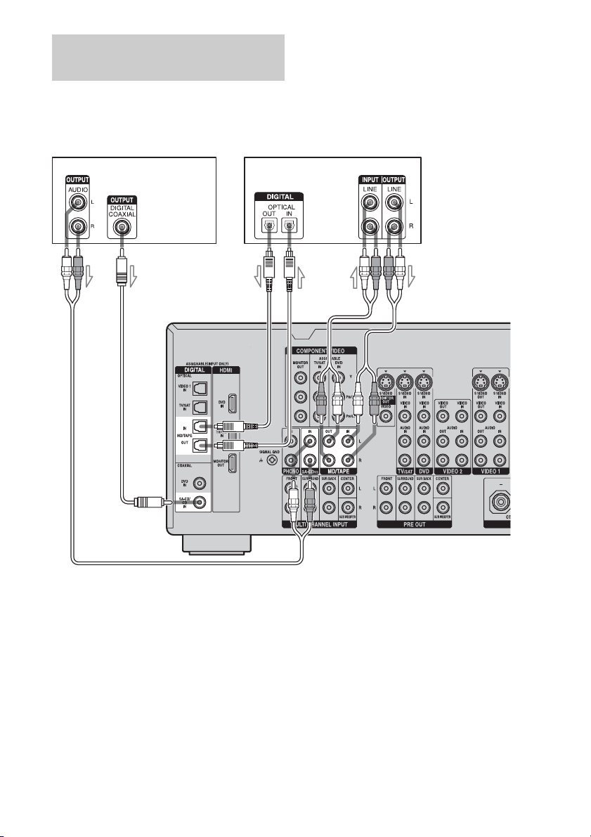
Connecting components with
digital audio input/output jacks
The following illustration shows how to
connect a Super Audio CD player, CD player
and an MD/TAPE deck.
Super Audio CD
player, CD player
B
MD deck,
TAPE deck
C
A
A
A Audio cord (not supplied)
B Coaxial digital cord (not supplied)
C Optical digital cord (not supplied)
GB
20
Page 21

Notes on playing a Super Audio
CD on a Super Audio CD player
• No sound is output when playing a Super
Audio CD on a Super Audio CD player
connected to only the COAXIAL SA-CD/
CD IN jacks on this receiver. When you play
a Super Audio CD, connect the player to the
MULTI CHANNEL INPUT or SA-CD/CD
IN jacks. Refer to the operating instructions
supplied with the Super Audio CD player.
• You cannot make digital recordings of a
Super Audio CD. Use the analog jack for
recording in this case.
• When connecting optical digital cords, insert
the plugs straight in until they click into
place.
• Do not bend or tie digital optical cords.
If you want to connect several
digital components, but cannot
find an unused input
See “Listening to digital sound from other
inputs (DIGITAL ASSIGN)” (page 86).
Tip
You cannot connect an LD player’s DOLBY
DIGITAL RF OUT jack directly to this receiver’s
digital input jacks. You must use an RF demodulator
for this configuration.
Getting Started
21
GB
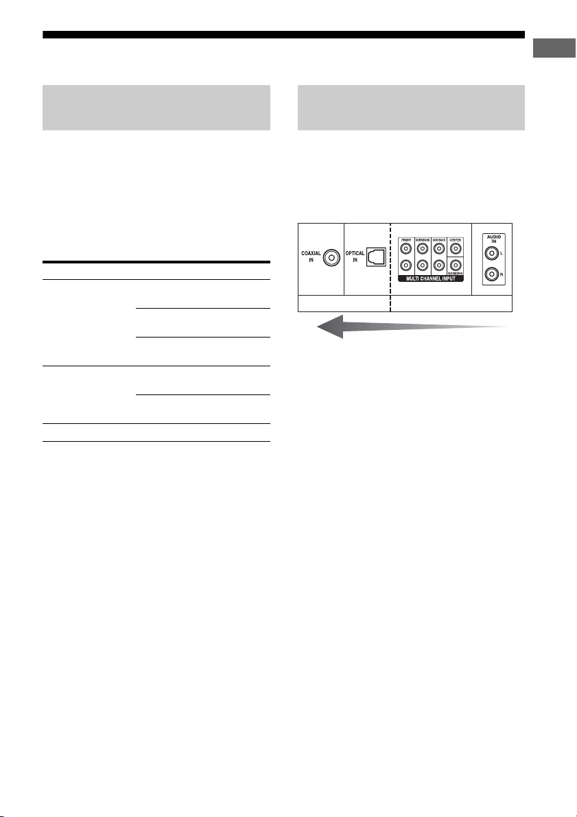
Page 22
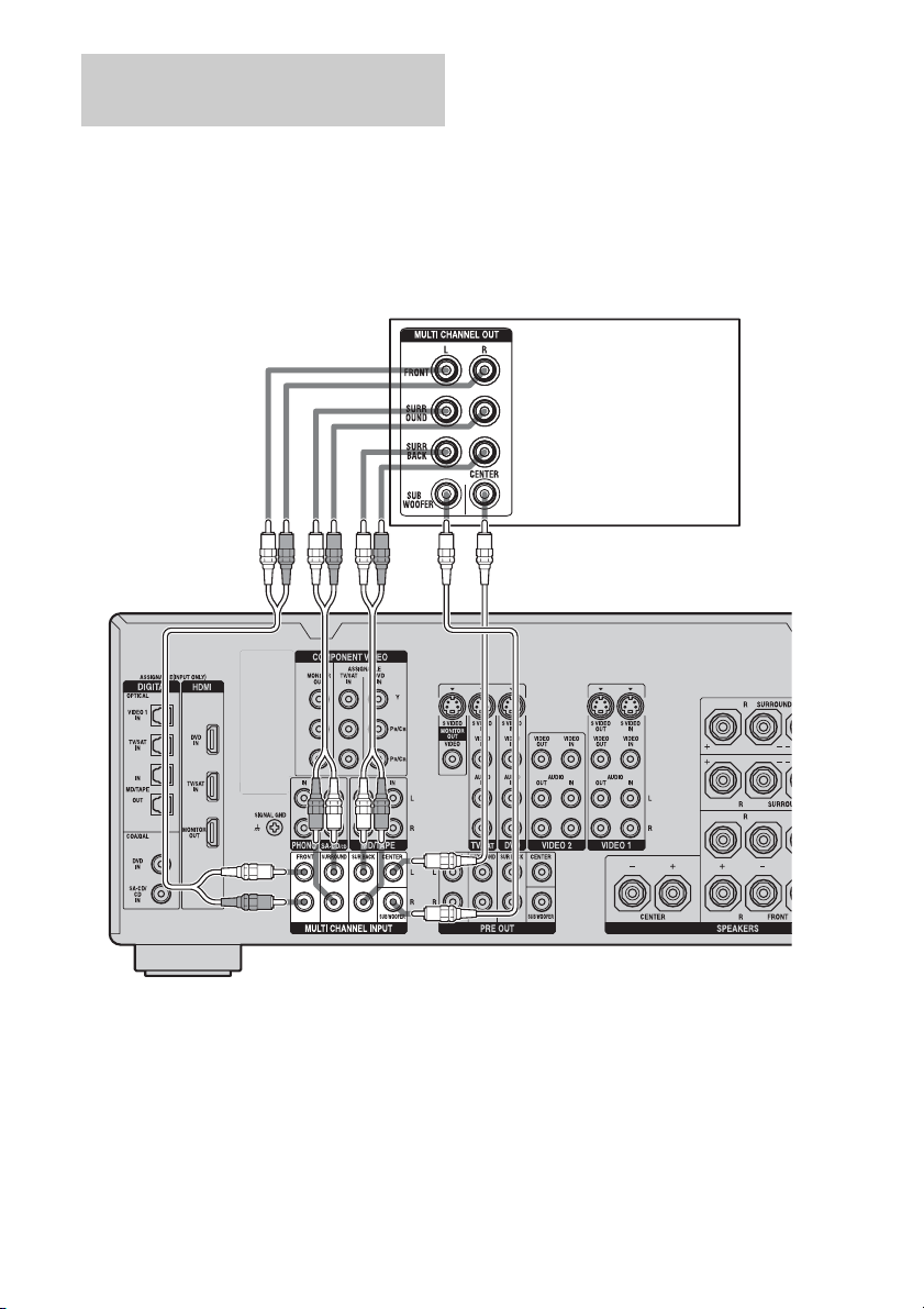
Connecting components with
multi-channel output jacks
If your DVD or Super Audio CD player is
equipped with multi-channel output jacks, you
can connect it to the MULTI CHANNEL
INPUT jacks of this receiver to enjoy multichannel sound. Alternatively, the multichannel input jacks can be used to connect an
external multi-channel decoder.
AB
DVD player, Super Audio
CD player, etc.
A Audio cord (not supplied)
B Monaural audio cord (not supplied)
Note
DVD and Super Audio CD players do not have the
SURROUND BACK jacks.
GB
22
Page 23
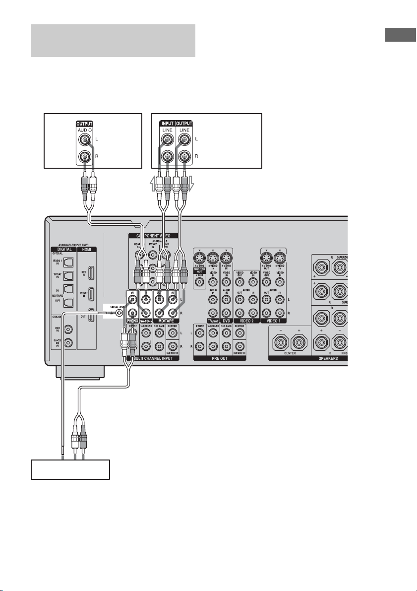
Connecting components with
analog audio jacks
The following illustration shows how to
connect a component with analog jacks, such
as tape deck, turntable, etc.
Getting Started
A
Super Audio
CD player,
CD player
A
A
MD deck,
TAPE deck
Turntable
A Audio cord (not supplied)
Note
If your turntable has a ground (earth) wire, connect
it to the (U) SIGNAL GND terminal.
23
GB
Page 24
3b: Connecting the video components
How to hook up your
components
This section describes how to hook up your
components to this receiver. Before you begin,
refer to “Component to be connected” below
for the pages which describe how to connect
each component.
After hooking up all your components,
proceed to “4: Connecting the antennas
(aerials)” (page 35).
Component to be connected Page
With HDMI jack 25
TV monitor 27
DVD player, DVD recorder 29-30
Satellite tuner 31
VCR 32
Camcorder, video game, etc. 32
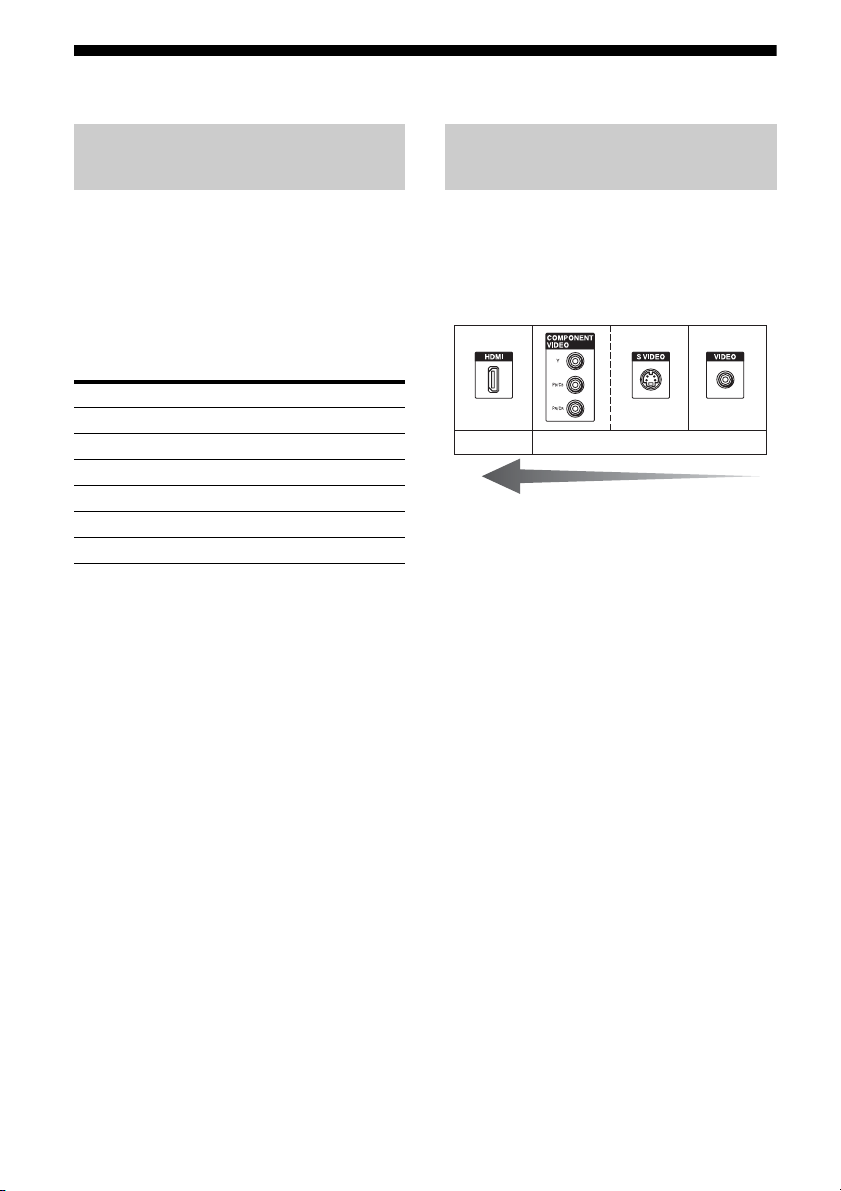
Video input/output jacks to be
connected
The image quality depends on the connecting
jack. Refer to the illustration that follows.
Select the connection according to the jacks on
your components.
Digital Analog
High quality image
24
GB
Page 25
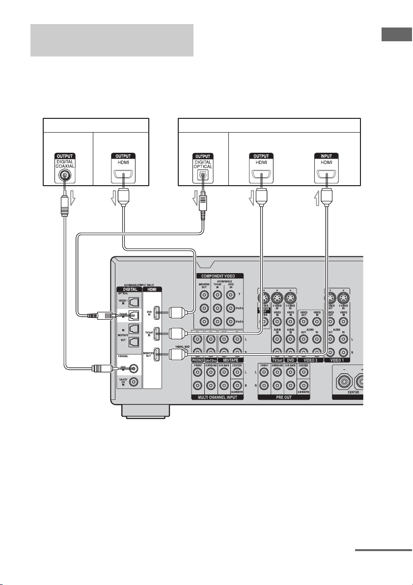
Connecting components with
HDMI jacks
HDMI is the abbreviated name for HighDefinition Multimedia Interface. It is an
interface which transmits video and audio
signals in digital format.
DVD player Satellite tuner/TV monitor, projector, etc.
Audio
signals
Audio/video
signals
Audio
signals
Audio/video
signals
Getting Started
AAA
A HDMI cable (not supplied)
We recommend that you use a Sony HDMI cable.
B Coaxial digital cord (not supplied)
C Optical digital cord (not supplied)
CB
continued
25
GB
Page 26

Notes on HDMI connections
• Audio signals input to the HDMI IN jacks
are output from the HDMI OUT jack. The
input audio signals are not output from the
speaker output jacks, PRE OUT jacks and
any other audio output jacks.
• You must connect audio or digital cords to
output sound from the receiver (page 29, 31).
• Video signals input to the HDMI IN jack can
only be output from the HDMI OUT jack.
The input video signals cannot be output
from the VIDEO OUT jacks, S VIDEO
OUT jacks, or MONITOR OUT jacks.
• Use an HDMI cable with the HDMI logo
(made by Sony).
• Check the setup of the connected component
if an image is poor or the sound does not
come out of a component connected via the
HDMI cable.
• Be sure to turn on the receiver when video
and audio signals of a playback component
are being output to a TV through this
receiver. Unless the power is on, neither
video nor audio signals will be transmitted.
• This receiver may not be able to transfer
video or audio signals with certain types of
components.
• Refer to the operating instructions of each
component connected for details.
26
GB
Page 27
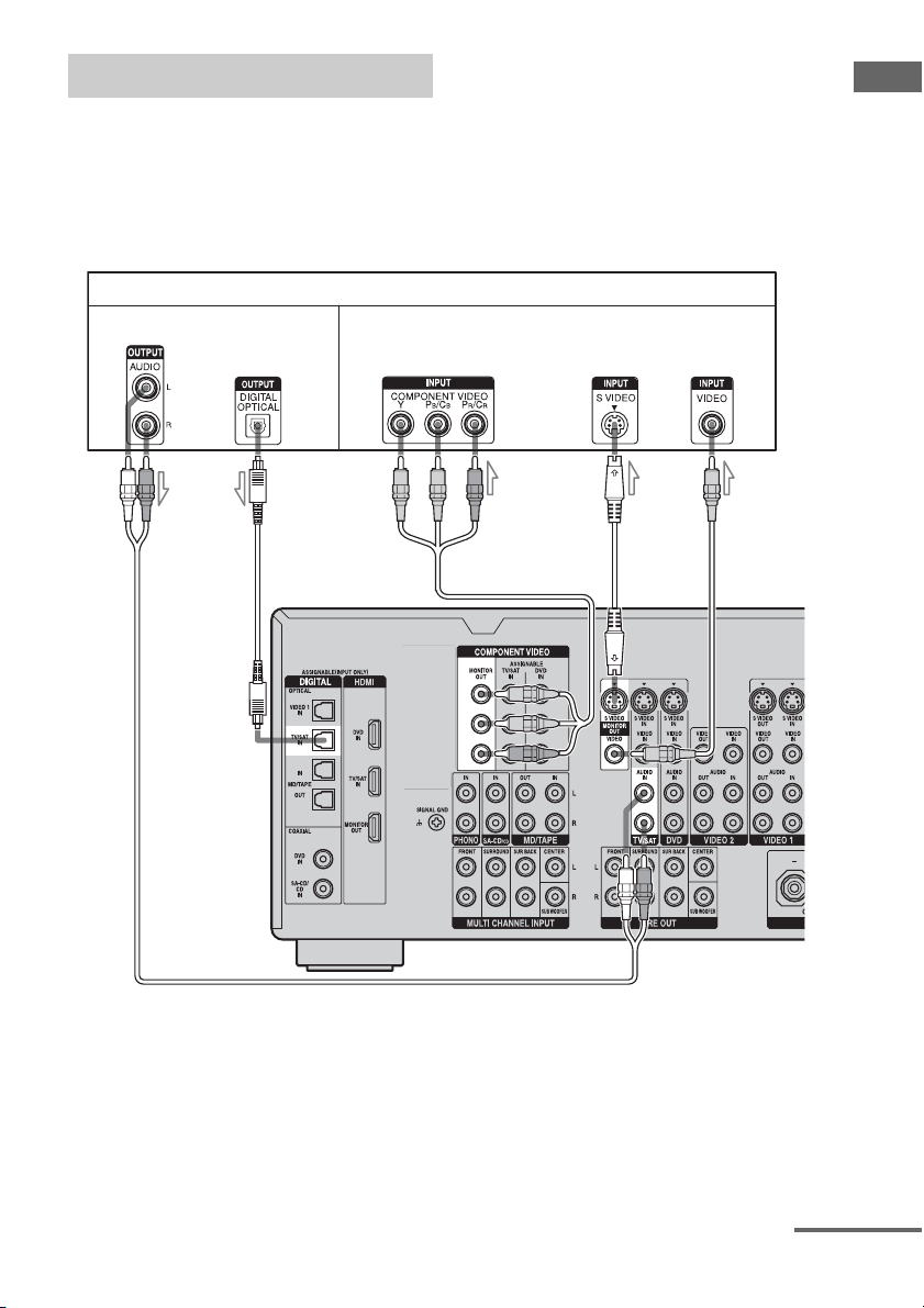
Connecting a TV monitor
The image from a visual component connected
to this receiver and the menu of this receiver
can be displayed on a TV screen.
It is not necessary to connect all the cables.
Connect audio and video cords according to
the jacks of your components.
TV monitor
Audio signals Video signals
AB C DE
Getting Started
A Audio cord (not supplied)
B Optical digital cord (not supplied)
C Component video cord (not supplied)
D S video cord (not supplied)
E Video cord (not supplied)
continued
27
GB
Page 28

Notes
• Connect image display components such as a TV
monitor or a projector to the MONITOR OUT jack
on the receiver. You may not be able to record, even
if you connect recording components.
• Turn on the receiver when the video and audio of a
playback component are being output to a TV via
the receiver. If the power supply of the receiver is
not turned on, neither video nor audio is
transmitted.
• Depending on the status of the connection between
the TV and the antenna (aerial), the image on the
TV screen may be distorted. In this case, place the
antenna (aerial) farther away from the receiver.
Tips
• The receiver has a video conversion function. For
details, see “Notes on converting video signals”
(page 34).
• You can watch the selected input image when you
connect the MONITOR OUT jack to a TV monitor.
You can also display certain menu settings and the
sound field on the monitor when you press ON
SCREEN (page 83).
• The sound of the TV is output from the speakers
connected to the receiver if you connect the sound
output jack of the TV and the TV/SAT AUDIO IN
jacks of the receiver. In this configuration, set the
sound output jack of the TV to “Fixed” if it can be
switched between either “Fixed” or “Variable.”
28
GB
Page 29
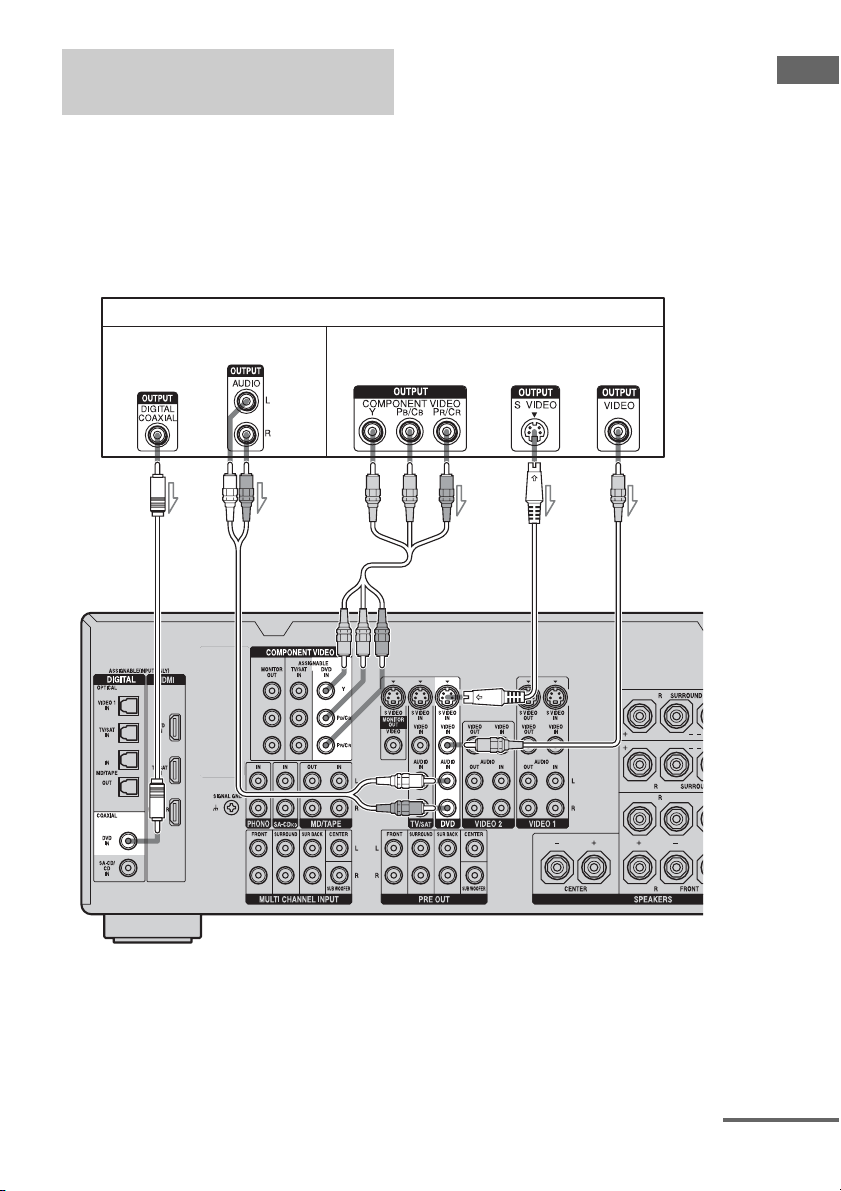
Connecting a DVD player/DVD
recorder
Getting Started
The following illustration shows how to
connect a DVD player/DVD recorder.
It is not necessary to connect all the cables.
Connect audio and video cords according to
the jacks of your components.
Connecting a DVD player
DVD player
Audio signals Video signals
AB C
Note
To output multi-channel digital audio, set the digital
audio output setting on the DVD player. Refer to the
operating instructions supplied with the DVD
player.
DE
A Coaxial digital cord (not supplied)
B Audio cord (not supplied)
C Component video cord (not supplied)
D S video cord (not supplied)
E Video cord (not supplied)
continued
29
GB
Page 30
Connecting a DVD recorder
DVD recorder
Audio signals Video signals
AB
A Optical digital cord (not supplied)
B Audio cord (not supplied)
C Video cord (not supplied)
D S video cord (not supplied)
CD
30
GB
Page 31

Connecting a satellite tuner
The following illustration shows how to
connect a satellite tuner.
It is not necessary to connect all the cables.
Connect audio and video cords according to
the jacks of your components.
Audio signals Video signals
AB CDE
Getting Started
Satellite tuner
A Optical digital cord (not supplied)
B Audio cord (not supplied)
C Component video cord (not supplied)
D S video cord (not supplied)
E Video cord (not supplied)
31
GB
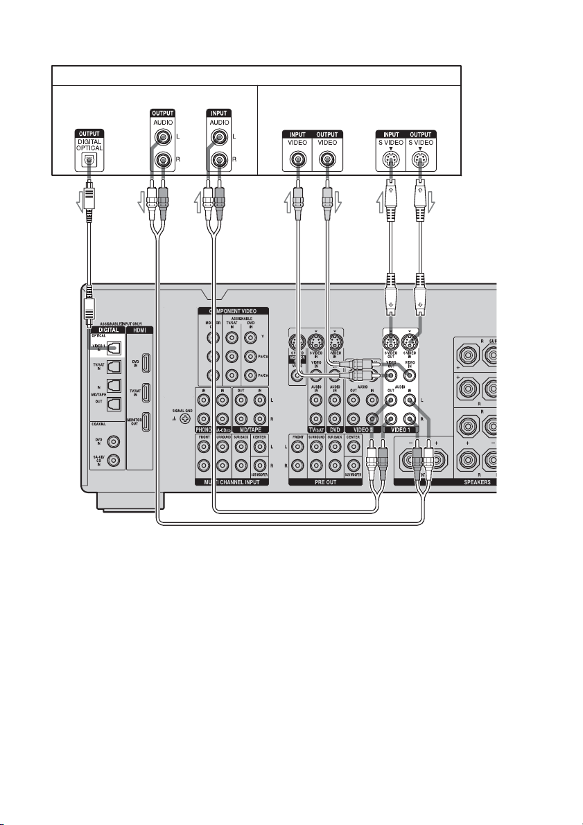
Page 32

Connecting components with
analog video and audio jack
The following illustration shows how to
connect a component which has analog jacks
such as a VCR, etc.
VCR
Audio signals Video signals
A
It is not necessary to connect all the cables.
Connect audio and video cords according to
the jacks of your components.
B
A Audio cord (not supplied)
B Video cord (not supplied)
GB
32
Camcorder,
video game
To the VIDEO 3 IN/PORTABLE
AV IN jacks (Front panel)
C
D
C S video cord (not supplied)
D Audio/video cord (not supplied)
Page 33

Function for conversion of video
signals
Getting Started
This receiver is equipped with a function for
converting video signals. You can output the
video signal after connecting this receiver via
the MONITOR OUT jack as shown in the
illustration.
• Composite video signals can be output as
S video signals and component video
signals.
• S video signals can be output as component
video signals.
In the video input/output conversion table of the receiver
Input Signals
Output Signals
C D
D
B C D
A
OUTPUT jack
INPUT jack
HDMI IN A f XXX
COMPONENT
VIDEO IN B
S VIDEO IN C X afX
VIDEO IN D X aaf
a : Video signals are converted and output through the video converter.
f : The same type of signal as that of the input signal is output. Video signals are not converted.
X : Video signals are not output.
HDMI OUT
X f XX
COMPONENT VIDEO
MONITOR OUT
S VIDEO
MONITOR OUT
VIDEO
MONITOR OUT
continued
33
GB
Page 34

Notes on converting video signals
• You cannot down-convert input signals
using the receiver. Component video signals
cannot be converted to S video signals and
composite video signals. S video signals
cannot be converted to composite video
signals. HDMI video signals cannot be
converted to component video signals,
S video signals, and video signals.
• When video or S video signals from a VCR,
etc., are converted on this receiver and then
output to your TV, depending on the status of
the video signal output, the image on the TV
screen may appear distorted horizontally or
no image may be output.
• The converted video signals are output only
from the MONITOR OUT jacks. They are
not output from VIDEO OUT jacks or
S VIDEO OUT jacks.
• When you play a VCR with an image
improvement circuit, such as TBC, the
images may be distorted or may not be
output. In this case, set the image
improvement circuit function to off.
• The video conversion function does not
work with SECAM video signals.
Closed Caption display
When the receiver receives video output
signals that are up-converted but the
accompanying closed caption cannot be
displayed, down-convert the video output
signals to the original video signals, and
connect the TV to the MONITOR OUT jack
that outputs the original video signals.
To connect a recording
component
When recording, connect the recording
component to the VIDEO OUT jacks or S
VIDEO OUT jacks of the receiver. Connect
cords for input and output signals to the same
type of jack, as VIDEO OUT jacks and S
VIDEO OUT jacks do not have an upconversion function.
34
Note
Signals output from the MONITOR OUT jacks may
not be recorded properly.
GB
Page 35

4: Connecting the antennas (aerials)
Connect the supplied AM loop antenna
(aerial) and FM wire antenna (aerial).
FM wire antenna (aerial) (supplied)
AM loop antenna (aerial) (supplied)
Getting Started
* The shape of the connector varies depending on
the area.
Notes
• To prevent noise pickup, keep the AM loop antenna
(aerial) away from the receiver and other
components.
• Be sure to fully extend the FM wire antenna
(aerial).
• After connecting the FM wire antenna (aerial),
keep it as horizontal as possible.
• Do not use the U SIGNAL GND terminal for
grounding the receiver.
35
GB
Page 36

5: Preparing the receiver and the remote
Connecting the AC power cord
(mains lead)
Connect the supplied AC power cord (mains
lead) to the AC IN terminal on the receiver,
then connect the AC power cord (mains lead)
to a wall outlet.
AC IN terminalAC OUTLET*
• Make sure that the total power consumption of the
component(s) connected to the receiver’s AC
OUTLET(s) does not exceed the wattage stated on
the rear panel. Do not connect high-wattage
electrical home appliances such as electric irons,
fans, or TVs to this outlet. This may cause a
malfunction.
Performing initial setup
operations
Before using the receiver for the first time,
initialize the receiver by performing the
following procedure. This procedure can also
be used to return settings you have made to
their factory defaults.
1,2 2,3 2,3
To the wall outlet
* The configuration, shape, number of AC outlets,
and the information displayed on the label will
vary according to the area.
AC power cord
(mains lead)
(supplied)
**
** A several space is left between the plug and the
rear panel even when the power cord (mains
lead) is inserted firmly. The cord is supposed be
connected this way. This is not malfunction.
Notes
• The AC OUTLET(s) on the rear of the receiver is a
switched outlet, which supplies power to the
connected component only while the receiver is
turned on.
GB
36
1 Press POWER to turn off the
receiver.
2 Press POWER while pressing
TONE MODE and MULTI CH IN.
3
Release TONE MODE and MULTI
CH IN after a few seconds.
After “MEMORY CLEARING...”
appears on the display for a while,
“MEMORY CLEARED!” appears.
The following items are reset to their
factory settings.
• All settings in the Level Settings, EQ
Settings, Sur Settings, Tuner Settings,
Audio Settings, Video Settings, Speaker
Settings, System Settings, and Auto
Calibration menus.
• The sound field memorized for each
input and preset station.
• All preset stations.
• All index names for inputs and preset.
Page 37

Inserting batteries into the
remote
Insert two R6 (size-AA) batteries in the RMAAP015 remote commander.
Observe the correct polarity when installing
batteries.
RM-AAP015
Notes
• Do not leave the remote in an extremely hot or
humid place.
• Do not use a new battery with old ones.
• Do not mix manganese batteries and other kinds of
batteries.
• Do not expose the remote sensor to direct sunlight
or lighting apparatuses. Doing so may cause a
malfunction.
• If you do not intend to use the remote for an
extended period of time, remove the batteries to
avoid possible damage from battery leakage and
corrosion.
• When you replace the batteries, the programmed
remote codes may be cleared. If this happens,
program the remote codes again (page 94).
Tip
When the remote no longer operates the receiver,
replace all the batteries with new ones.
About the command mode
The receiver and the remote use the same
command mode.
If the command modes of the receiver and the
remote are different, you cannot use the
remote to operate the receiver.
If the command modes of both the receiver and
the remote are those of the initial setting (AV
SYSTEM 2), it is not necessary to reset them.
You can switch the command mode (AV
SYSTEM 1 or AV SYSTEM 2) of the receiver
and the remote. If both the receiver and the
other Sony component respond to the same
remote command, switch the command mode
of either the component or the receiver to
another command mode so that the component
does not respond to the same remote command
as the receiver.
To switch the command mode
of the receiver
2CH
Turn on the receiver while pressing
2CH.
When the command mode is set to “AV2,”
“COMMAND MODE [AV2]” appears on the
display.
When the command mode is set to “AV1,”
“COMMAND MODE [AV1]” appears on the
display.
Getting Started
continued
37
GB
Page 38

To switch the command mode
of the RM-AAP015 remote
6: Setting the speakers
1
2
3
1 Press RM SET UP.
The RM SET UP button flashes.
2 Press 1 or 2 while the RM SET
UP button is flashing.
When you press 1, the command mode is
set to AV SYSTEM 1. When you press 2,
the command mode is set to AV SYSTEM
2.
3 Press ENTER when the RM SET
UP button lights up.
The RM SET UP button flashes twice,
then the command mode setting process
is completed.
Tip
When you press RM SET UP, use a thin wire, such
as a paper clip.
Setting the speaker impedance
Set the appropriate speaker impedance for the
speakers you are using.
1
2
4-6
3,7
1 Turn on the receiver.
2 Press RECEIVER.
Receiver operation is enabled.
3 Press MENU.
The list of setting menus appears.
38
4 Press V/v repeatedly to select
“System Settings,” then press
to enter.
5 Press V/v repeatedly to select
“SP. IMPEDANCE,” then press
to enter the parameter.
GB
Page 39

6 Press V/v repeatedly to select
“4 ohm” or “8 ohm” depending
on the speakers you are using,
then press to enter the
selection.
7 Press MENU to exit the menu.
Notes
• If you are not sure of the impedances of the
speakers, refer to the operating instructions
supplied with your speakers. (This information is
often on the back of the speaker.)
• When you connect all speakers with a nominal
impedance of 8 ohms or higher, set “SP.
IMPEDANCE” to “8 ohm.” When connecting
other types of speakers, set it to “4 ohm.”
• When you connect front speakers to both the
SPEAKER A and B terminals, connect the
speakers with a nominal impedance of 8 ohms or
higher.
– When you connect speakers with impedance of
16 ohms or higher in both “A” and “B”
configuration:
Set “SP. IMPEDANCE” to “8 ohm” in the
System Settings menu.
– For other types of speakers in other
configurations:
Set “SP. IMPEDANCE” to “4 ohm” in the
System Settings menu.
Note
You cannot switch the front speakers by pressing
SPEAKER (OFF/A/B/A+B) when the headphones
are connected to the receiver.
Set to To select
A The speakers connected to the
FRONT SPEAKERS A terminals.
B The speakers connected to the
FRONT SPEAKERS B terminals.
A+B The speakers connected to both the
FRONT SPEAKERS A and B
terminals (parallel connection).
OFF No audio signals are output from
any speaker terminals, or the PRE
OUT terminal.
Getting Started
Selecting the front speaker
You can select the front speakers you want to
drive.
SPEAKERS (OFF/A/B/A+B)
Press SPEAKERS (OFF/A/B/A+B)
repeatedly to select the front
speaker system you want to drive.
39
GB
Page 40

7: Calibrating the
appropriate settings
– MULTI IN is selected.
– The ANALOG DIRECT function is being used.
– Headphones are connected.
• Cancel MUTING if it is set to on.
automatically
(AUTO
CALIBRATION)
The DCAC (Digital Cinema Auto Calibration)
function allows you to perform automatic
calibration, such as checking the connection
between each speaker and the receiver,
adjusting the speaker level, and measuring the
distance of each speaker from your listening
position automatically. Refer also to the “Quick
Setup Guide” supplied with the receiver.
Before you perform auto
calibration
Before you perform the auto calibration, set up
and connect the speakers (page 16, 17).
• The AUTO CAL MIC jack is used for the
supplied optimizer microphone only. Do not
connect other microphones to this jack.
Doing so may damage the receiver and the
microphone.
• During the calibration, the sound that comes
out of the speakers is very loud. Pay
attention to the presence of children or to the
effect on your neighborhood.
• Perform the auto calibration in a quiet
environment to avoid the effect of noise and
get a more accurate measurement.
• If there are any obstacles in the path between
the optimizer microphone and the speakers,
the calibration cannot be performed
correctly. Remove any obstacles from the
measurement area to avoid measurement
error.
• When you use a bi-amplifier connection, set
“SUR BACK SP” to “BI-AMP” in the
Speaker Settings menu before you perform
auto calibration (page 64).
Notes
• The auto calibration function does not work in the
following cases.
Optimizer microphone
1 Connect the supplied optimizer
microphone to the AUTO CAL
MIC jack on the front panel.
2
Set up the optimizer microphone.
Place the optimizer microphone at your
listening position. Use a stool or tripod so
that the optimizer microphone remains at
the same height as your ears.
On setting up the active sub
woofer
• When a sub woofer is connected, turn on the
sub woofer and turn up the volume
beforehand. Turn the VOLUME knob to just
before the mid-point.
• If you connect a sub woofer with a crossover
frequency function, set the value to the
maximum.
• If you connect a sub woofer with an auto
standby function, set this function to off
(deactivated).
40
GB
Page 41

1
Getting Started
Note
Depending on the characteristics of the sub woofer
you are using, the setup distance value may be
further away from the actual position.
Using the receiver as a preamplifier
You can use the auto calibration function when
you use the receiver as a pre-amplifier.
In this case, the distance value shown on the
display may differ from the actual distance
value. However, there will be no problems
even if you continue to use the receiver with
that value.
Performing auto calibration
The auto calibration function allows you to
measure the following:
• Whether or not speakers are connected
• Polarity of speakers
• Distance of each speaker from your listening
• Speaker size
• Speaker level
• Frequency characteristics
a)
This receiver corrects signals by analog downmix
processing only for the center speaker and sub
woofer when MULTI IN is selected. The
correction is invalid for other speakers.
b)
The measurement result is not utilized when
MULTI IN is selected.
c)
• DTS 96/24 signals are always played back as 48
• The measurement result is not utilized in the
b)
position
kHz when you correct signals.
following cases.
– MULTI IN is selected.
b)
c)
a)
3
2
5-8
4
1 Turn on the receiver and the TV.
2 Press ON SCREEN.
Switch the input of the TV so that the
setting menu is displayed on the TV
screen connected to this receiver.
3 Press RECEIVER.
Receiver operation is enabled.
4 Press MENU.
The list of setting menus appears.
5 Press V/v repeatedly to select
“Auto Calibration,” then press
to enter the menu.
continued
41
GB
Page 42

6 Press V/v repeatedly to select
“CAL TYPE,” then press to
enter the parameter.
7 Press V/v repeatedly to select
the parameter, then press to
enter the selection.
Calibration
type
ENGINEER Sets the frequency
FULL FLAT Makes the measurement of
FRONT REF Adjusts the characteristics
Explanation
characteristics to a set that
matches that of the Sony
listening room standard.
frequency from each
speaker flat.
of all the speakers to match
the characteristics of the
front speaker.
8 Press V/v repeatedly to select
“AUTO CAL START,” then press
to start the measurement.
9 Measurement starts.
The measurement process will take
approximately 30 seconds. Wait until the
measurement process completes.
Note
You cannot measure the speaker height of the
surround speakers and the surround back speakers.
Set this value from “SP POSI.” settings in the
Speaker Settings menu (page 66).
Tips
• Operations other than turning the receiver on or off
and pressing ON SCREEN to turn the display on or
off are deactivated during auto calibration.
• When special speakers, such as dipole speakers are
used, the measurements may not be performed
correctly or auto calibration cannot be performed.
To cancel auto calibration
Auto calibration is cancelled when you change
the volume, switch functions, change the
speaker setting of the receiver, or connect
headphones.
Measurement starts in five seconds. A
countdown appears on the TV screen.
While the time is counting down, stand
away from the measurement area to
avoid measurement error.
GB
42
Page 43
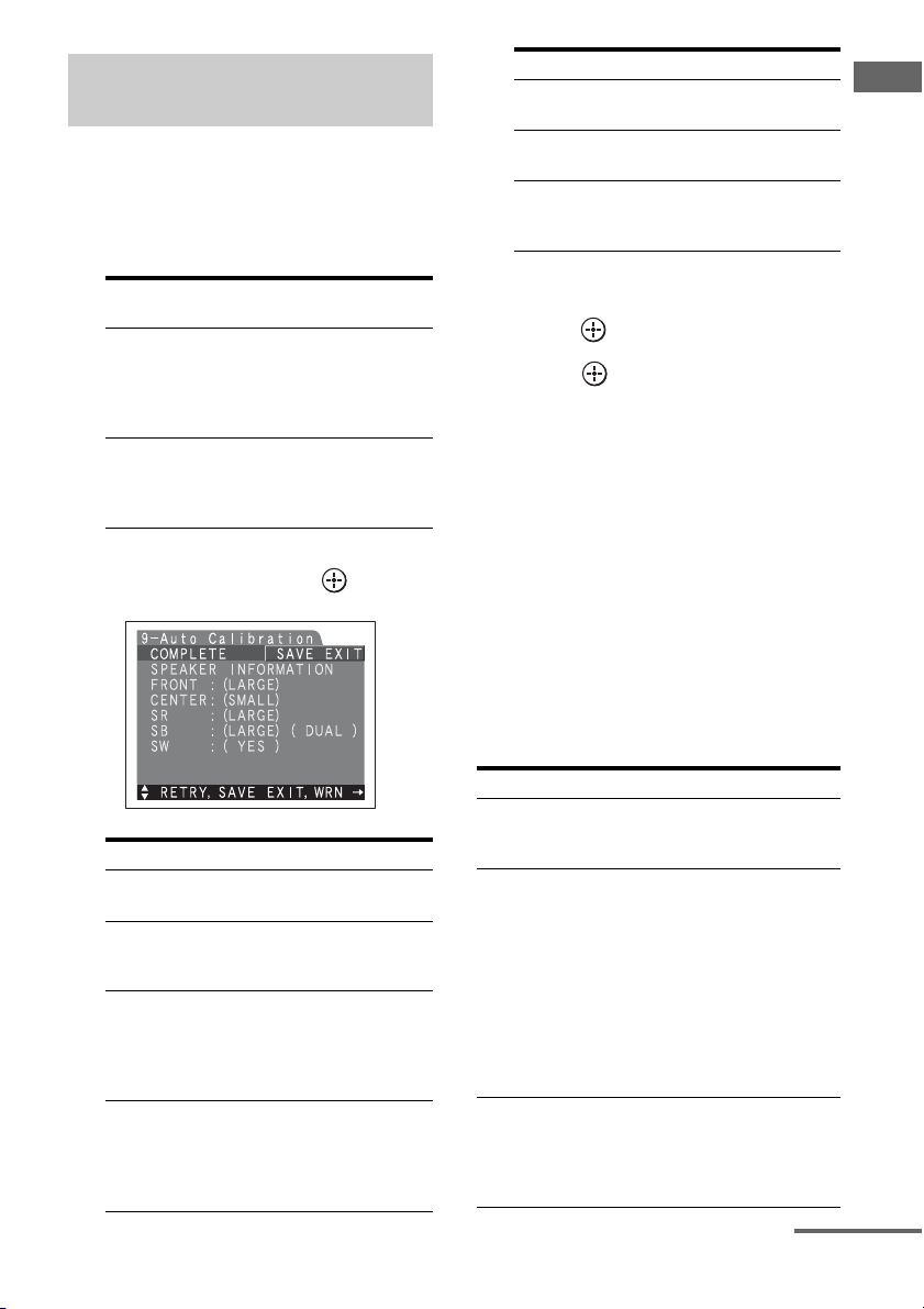
Confirming/saving the
measurement results
1 Confirm the measurement
result.
When the measurement ends, a beep
sounds and the measurement result
appears on the display.
Measurement
result
When the
measurement
process
completes
properly
When the
measurement
process fails
Display Explanation
COMPLETE
ERROR
CODE XX
Proceed to step
2.
See “When
error codes
appear” (page
43).
2 Press V/v repeatedly to select
the item, then press .
Item Explanation
RETRY Re-performs the auto
SAVE EXIT Saves the measurement
WRN CHECK Displays a warning
PHASE INFO Displays the phase of each
calibration.
results and exits the setting
process.
concerning the
measurement results. See
“When you select “WRN
CHECK”” (page 44).
speaker (in phase/out of
phase). See “When you
select “PHASE INFO””
(page 44).
Item Explanation
DIST.INFO Displays the measurement
result for speaker distance.
LEVEL INFO Displays the measurement
result for speaker level.
EXIT Exits the setting process
without saving the
measurement results.
3 Press V/v repeatedly to select a
preset number to be used, then
press .
4 Press .
The measurement results are saved.
Tip
The size of a speaker (LARGE/SMALL) is
determined by the low characteristics. The
measurement results may vary, depending on the
position of the optimizer microphone and speakers,
and the shape of the room. It is recommended that
you follow the measurement results. However, you
can change those settings in the Speaker Settings
menu (page 63). Save the measurement results first,
then try to change the settings if you want.
When error codes appear
Try the remedies and re-perform the auto
calibration.
Error code Cause and remedies
CODE 31 SPEAKERS (OFF/A/B/A+B) is
set to OFF. Set it to others and reperform the auto calibration.
CODE 32 None of the speakers were
detected. Make sure that the
optimizer microphone is
connected properly and reperform the auto calibration.
If the optimizer microphone is
connected properly but the error
code appears, the optimizer
microphone cable may be
damaged or improperly
connected.
CODE 33 (F) None of the front speakers are
connected or only one front
speaker is connected. The
optimizer microphone is not
connected.
continued
43
Getting Started
GB
Page 44

Error code Cause and remedies
CODE 33 (SR) • Either the left or right surround
CODE 33 (SB) The surround back speaker is
speakers is not connected.
• Surround back speakers are
connected even though
surround speakers are not
connected. Connect the
surround speaker to the
SURROUND terminals.
connected only to the
SURROUND BACK
SPEAKERS R terminals. When
you connect only one surround
back speaker, connect it to the
SURROUND BACK
SPEAKERS L terminals.
•CODE 31
1
Press , then follow the instructions from step
1 of “Performing auto calibration.”
•CODE 32, 33
When you press , “RETRY?” appears.
1
2 Press V/v to select “YES,” then press .
3 Follow the instructions from step 2 of
“Performing auto calibration.”
4 Press V/v repeatedly to select preset number to
store preset settings then press .
When you select “WRN CHECK”
If a warning on the measurement result is
present, detailed information is displayed.
Press to return to step 1 of
“Confirming/saving the
measurement results.”
Warning code Explanation
WARNING 41 The sound input from the
optimizer microphone is outside
the acceptable range. It is louder
than the loudest sound that can be
measured. Try to perfo rm the auto
calibration when the environment
is quiet enough to allow proper
measurement.
WARNING 42 The volume of the receiver is out
of the acceptable range. Try to
perform the auto calibration when
the environment is quiet enough
to allow proper measurement.
WARNING 4 3 The distance and position of a sub
woofer cannot be detected. Or the
angle of the speaker position
cannot be detected. This may be
caused by noise. Try to perform
the auto calibration in a quiet
environment.
NO WARNING There is no warning information.
When you select “PHASE INFO”
You can check the phase of each speaker (in
phase/out of phase).
Press V/v repeatedly to select a
speaker, then press to return to
step 1 in “Confirming/saving the
measurement results.”
Warning code Explanation
WARNING 40 The auto calibration has
GB
44
completed. However, the noise
level is high. You may be able to
perform the auto calibration
properly if you try it again, even
though the measurement cannot
be performed in all environments.
Try to perform the auto
calibration in a quiet
environment.
Page 45

Display Explanation
IN-PHASE The speaker is in phase.
OUT-OFPHASE
---------- No speakers are connected.
The speaker is out of phase. The
“+” and “–” terminals of the
speaker may be connected the
other way around. However,
depending on the speakers,
“OUT-OF-PHASE” appears on
the display even though the
speakers are connected properly.
This is because of the speakers’
specifications. In this case, you
can continue to use the receiver.
Tip
Depending on the position of the sub woofer, the
measurement results for polarity may vary.
However, there will be no problems even if you
continue to use the receiver with that value.
Auto Calibration menu
parameters
x AUTO CAL START?
(Starts auto calibration)
• MEASUREMENT COUNTDOWN
A time countdown appears on the display
from five seconds to one second.
• MEASURING TONE
Appears while TONE is being measured.
• MEASURING T.S.P.
Appears while TSP is being measured.
• MEASURING WOOFER
Appears while WOOFER is being
measured.
•COMPLETE
Appears when the measurement process
completes successfully. For details on each
message, see “Confirming/saving the
measurement results” (page 43).
• WARNING CODE xxx:4x
Appears if a warning on the measurement
result is present. For details on each
message, see “Confirming/saving the
measurement results” (page 43).
• NO WARNING
There is no warning information.
• ERROR CODE xxx:3x
Appears when the measurement fails. For
details on each message, see “Confirming/
saving the measurement results” (page 43).
•RETRY?
Appears to ask you to re-measure or exit
without re-measuring when the
measurement fails.
• CANCEL
Appears when you cancel auto calibration
during the measurement.
x CAL TYPE*
(Parameter type)
• ENGINEER
Sets the frequency to one that matches that
of the Sony listening room standard.
•FULL FLAT
Makes the measurement of frequency from
each speaker flat.
• FRONT REF
Adjusts the characteristics of all the speakers
to match the characteristics of the front
speaker.
x EQ CURVE EFFECT*
(Activates/deactivates the EQ
curve measurement)
•OFF
Deactivates the EQ curve measurement.
•ON
Activates the EQ curve measurement.
After the measurement is completed, this
setting is set to ON automatically.
*
The frequency response measurement result is not
utilized in the following cases.
– MULTI IN is selected.
Getting Started
continued
45
GB
Page 46

x A.CAL LOAD?
(Loads a preset measurement)
•PRESET-1
Loads the measurement value stored as
“PRESET-1.”
•PRESET-2
Loads the measurement value stored as
“PRESET-2.”
•PRESET-3
Loads the measurement value stored as
“PRESET-3.”
•OFF
Select this when you do not want to load a
preset value.
x A.CAL SAVE?
(Saves the measurement value)
•PRESET-1
Saves the measurement results as
“PRESET-1.”
•PRESET-2
Saves the measurement results as
“PRESET-2.”
•PRESET-3
Saves the measurement results as
“PRESET-3.”
x A.CAL NAME?
(Naming inputs)
You can change the preset to name to
something more recognizable.
GB
46
Page 47

Playback
Selecting a component
1
Selected
input
VIDEO 1, 2 VCR, etc., connected to the
VIDEO 3 Video camera and TV game,
DVD DVD player, etc., connected
TV/SAT Satellite tuner, etc., connected
MD/TAPE MD or TAPE deck, etc.,
SA-CD/CD Super Audio CD or CD
TUNER Built-in radio tuner
PHONO Turntable, etc., connected to
MULTI IN Component connected to the
Components that can be
played back
VIDEO 1 or VIDEO 2 jack
etc., connected to the VIDEO
3 jack
to DVD jack
to the TV/SAT jack
connected to the MD/TAPE
jack
player, etc., connected to the
SA-CD/CD jack
the PHONO jack
MULTI CHANNEL INPUT
jack
Playback
3
MUTING
1
Press one of the input button.
You can also use INPUT SELECTOR on
the receiver. The selected input appears
on the display. To select a component
connected to the MULTI CHANNEL
INPUT jack, press MULTI CH IN button.
Switch the input signals from the
component connected to the HDMI IN
jack of the receiver to HDMI signals
using the TV, etc., connected to the HDMI
MONITOR OUT jack of the receiver.
2 Turn on the component and
start playback.
3 Press MASTER VOL +/– to
adjust the volume.
You can also use MASTER VOLUME on
the receiver.
The initial volume level is set to minimum
(muting).
To activate the muting function
Press MUTING on the remote. To cancel,
press MUTING on the remote again or turn
MASTER VOLUME clockwise to raise the
volume. Even if you turn off the receiver, the
muting function works when you turn the
receiver on again.
To avoid damaging your
speakers
Before you turn off the receiver, be sure to turn
down the volume level.
47
GB
Page 48

Listening to a Super Audio CD/CD
2
3
5
1 Turn on the Super Audio CD player or CD
• The operation is described for a
Sony Super Audio CD player.
• Refer to the operating
instructions supplied with the
Super Audio CD player or CD
player.
z
You can select the sound field to
suit the music. Refer to page 71
for details.
Recommended sound fields:
Classical: HALL
Jazz: JAZZ CLUB
Live concert: LIVE CONCERT,
STADIUM
player, then place the disc in the tray.
2 Turn on the receiver.
3 Press SA-CD/CD.
You can also use INPUT SELECTOR on the receiver to
select “SA-CD/CD.”
An example of the display
4 Play back the disc.
5
3
48
5 Adjust to a suitable volume.
6 After you have finished listening to a Super
Audio CD or CD, eject the disc and turn off
the receiver and the Super Audio CD player
or CD player.
GB
Page 49

Watching a DVD
2
3
7
• Refer to the operating
instructions supplied with the
TV and DVD player.
z
Select the sound format of the
disc to be played, if necessary.
z
You can select the sound field to
suit the movie or the music. Refer
to page 71 for details.
Recommended sound fields:
Movie: CINEMA STUDIO EX
Live image: LIVE CONCERT
Sport: SPORTS
Playback
7
3
MULTI CHANNEL DECODING lamp
1 Turn on the TV and DVD player.
2 Turn on the receiver.
3 Press DVD.
You can also use INPUT SELECTOR on this receiver to
select “DVD.”
An example of the display
4 Switch the input of the TV so that an image
of the DVD is displayed.
Check the following if you cannot
listen to the multi-channel sound.
• Be sure the sound source
corresponds to the multichannel format (the MULTI
CHANNEL DECODING lamp
on the front panel lights up
during playback).
• Be sure this receiver is
connected to the DVD player via
a digital connection.
• Be sure the digital audio output
of the DVD player is set up
properly.
5 Set up the DVD player.
Refer to “Quick Setup Guide” supplied with the receiver.
6 Play back the disc.
7 Adjust to a suitable volume.
8 After you have finished watching a DVD,
eject the disc and turn off the receiver, the
TV, and the DVD player.
49
GB
Page 50

Enjoying video games
2
3
VIDEO 3 IN/PORTABLE AV IN
7
1 Turn on the TV and video game.
• Refer to the operating
instructions supplied with the
TV and video game.
2 Turn on the receiver.
3 Press VIDEO 3*.
7
3
You can also use INPUT SELECTOR on this receiver to
select “VIDEO 3*.”
* When you connect a TV game to the VIDEO 3 IN/PORTABLE
AV IN jack on the front panel.
An example of the display
50
4 Switch the input of the TV so that an image
of the video game is displayed.
5 Set up the video game.
6 Place the disc in the tray and play it back on
the video game.
7 Adjust to a suitable volume.
8 After you have finished playing a game, eject
the disc and turn off the receiver, the TV, and
the video game.
GB
Page 51

Watching video
2
3
6
• Refer to the operating
instructions supplied with the
TV and VCR.
Playback
6
3
1 Turn on the VCR.
2 Turn on the receiver.
3 Press VIDEO 1*.
You can also use INPUT SELECTOR on this receiver to
select “VIDEO 1*.”
* When you connect VCR to the VIDEO 1 jack.
An example of the display
4 Switch the input of the TV so that an image
of the VCR is displayed.
5 Play back the tape on the VCR.
6 Adjust to a suitable volume.
7 After you have finished watching a video,
eject the tape and turn off the receiver, the
TV, and the VCR.
51
GB
Page 52

Amplifier Operations
To return to the previous
display
Press RETURN/EXIT O.
Navigating through menus
By using the amplifier menus, you can make
various adjustments to customize the receiver.
1
3-7
RETURN/
EXIT O
2
1 Press RECEIVER.
Receiver operation is enabled.
To exit the menu
Press MENU.
Note
Some parameters and settings may appear dimmed
on the display. This means that they are either
unavailable or fixed and unchangeable.
2 Press MENU.
The list of setting menus appears.
3 Press V/v repeatedly to select
the menu you want.
4 Press to enter the menu.
5 Press V/v repeatedly to select
the parameter you want to
adjust.
6 Press to enter the
parameter.
7 Repeat steps 3 to 6 when you
want to make other settings.
GB
52
Page 53

Overview of the menus
The following options are available in each
menu. For details on navigating through
menus, see page 52.
Menu Item Parameter Initial
1-Level
Settings
2-EQ Settings EQ PRESET [xxx] 1, 2, 3, 4, 5, OFF 1 page 57
TEST TONE
[xxxxxxxx]
PHASE NOISE
[xxxxxxx]
PHASE AUDIO
[xxxxxxx]
FRONT BAL. [xxx.x dB] R+20.0dB to L+20.0dB (0.5dB step) 0dB
CENTER [xxx.x dB] –20.0dB to +10.0dB (0.5dB step) 0dB
SURROUND L [xxx.x dB] –20.0dB to +10.0dB (0.5dB step) 0dB
SURROUND R [xxx.x dB] –20.0dB to +10.0dB (0.5dB step) 0dB
SUR BACK [xxx.x dB] –20.0dB to +10.0dB (0.5dB step) 0dB
SUR BACK L [xxx.x dB] –20.0dB to +10.0dB (0.5dB step) 0dB
SUR BACK R [xxx.x dB] –20.0dB to +10.0dB (0.5dB step) 0dB
SUB WOOFER [xxx.x dB] –20.0dB to +10.0dB (0.5dB step) 0dB
MULTI CH SW [xxx.x dB] 0dB, +10.0dB 0dB
D. RANGE COMP. [xxx] OFF, STD, MAX OFF
FRONT BASS [xxx dB] –10.0dB to +10.0dB (1dB step) 0dB
FRONT TREBLE [xxx dB] –10.0dB to +10.0dB (1dB step) 0dB
CENTER BASS [xxx dB] –10.0dB to +10.0dB (1dB step) 0dB
CENTER TREBLE [xxx
dB]
SUR/SB BASS [xxx dB] –10.0dB to +10.0dB (1dB step) 0dB
SUR/SB TREBLE [xxx dB] –10.0dB to +10.0dB (1dB step) 0dB
PRESET x CLEAR [
xxx] YES, NO NO
OFF, AUTO, FIX OFF page 56
OFF, L/C, C/R, R/SL, R/SR, SR/SL,
SR/SBR, SBR/SBL, SBL/SL, SL/L, L/
SR
OFF, L/C, C/R, R/SL, R/SR, SR/SL,
SR/SBR, SBR/SBL, SBL/SL, SL/L, L/
SR
–10.0dB to +10.0dB (1dB step) 0dB
setting
OFF
OFF
Refer
page
- 57
- 58
Amplifier Operations
continued
53
GB
Page 54

Menu Item Parameter Initial
setting
3-Sur Settings SOUND FIELD SELECT ? A.F.D
AUT O
SB DECODING [xxxx] OFF, AUTO, ON AUTO page 59
SB DEC MODE
[xxxxxxx]
DDEX, PLIIx MV, PLIIx MS PLIIx
MV
EFFECT LEVEL [xxx%] 20% to 120% (5% step) 100%
CENTER WIDTH [x]8 step 3
DIMENSION
FRONT +3 to SUR +3 0
[xxxxxxx]
PANORAMA MODE [xxx] OFF, ON OFF
SCREEN DEPTH [xxx] ON, OFF ON
VIR. SPEAKERS [xxx] ON, OFF ON
4-Tuner
Settings
5-Audio
FM MODE [xxxxxx] MONO, STEREO STEREO page 61
NAME IN? [xxx] page 84
DEC. PRIORITY [xxxx] PC M, AU TO AUTO page 62
Settings
DUAL MONO
[xxxxxxxx]
MAIN/SUB, MAIN, SUB,
MAIN+SUB
MAIN
A/V SYNC [xxxms] 0ms to 150ms/300ms (10 ms step) 0ms
DIGITAL ASSIGN ? page 86
NAME IN ? [xxx] page 84
6-Video
Settings
COMPONENT V. ASSIGN ? page 88
HDMI ASSIGN ? page 87
COLOR SYSTEM [xxxx] NTSC, PAL PAL page 63
NAME IN ?
[xxxxxxxx]
Refer
page
page 69
- 60
page 84
54
GB
Page 55

Menu Item Parameter Initial
setting
7-Speaker
Settings
SUB WOOFER [xxx] NO, YES YES page 63
FRONT SP [xxxxx] SMALL, LARGE LARGE
Refer
page
- 67
CENTER SP [xxxxx] MIX, NO, SMALL, LARGE LARGE
SURROUND SP [xxxxx] NO, SMALL, LARGE LARGE
SUR BACK SP [xxxxxx] BI-AMP, NO, SINGLE, DUAL DUAL
FRONT L x.xmeter* 1.0m to 7.0m (0.1m** step) 3.0 meter
FRONT R x.xmeter* 1.0m to 7.0m (0.1m** step) 3.0 meter
CENTER x.xmeter* 1.0m to 7.0m (0.1m** step) 3.0 meter
SURROUND L x.xmeter* 1.0m to 7.0m (0.1m** step) 3.0 meter
SURROUND R x.xmeter* 1.0m to 7.0m (0.1m** step) 3.0 meter
SUR BACK L x.xmeter* 1.0m to 7.0m (0.1m** step) 3.0 meter
SUR BACK R x.xmeter* 1.0m to 7.0m (0.1m** step) 3.0 meter
SUB WOOFER x.xmeter* 1.0m to 7.0m (0.1m** step) 3.0 meter
DISTANCE UNIT
meter, feet meter
[xxxxx]
SP POSI [xxxxxxxxx] SIDE/LOW, SIDE/HIGH, BEHD/
LOW, BEHD/HIGH
SIDE/
LOW
SP CROSSOVER [xxxHz] 40Hz to 200Hz (10Hz step) 120Hz
8-System
Settings
9-Auto
Calibration
DIMMER [xxx% DOWN] 0%, 60%, 100% 0% page 67
SP. IMPEDANCE [xxxx] 4 ohm, 8 ohm 8 ohm page 38
AUTO CAL START? page 45
CAL TYPE
[xxxxxxxxx]
ENGINEER/FULL FLAT/FRONT
REF
FULL FLAT
- 46
EQ CURVE EFFECT [xxx] OFF, ON OFF
A.CAL LOAD? [PRESET- x] OFF, PRESET1, PRESET2, PRESET3 OFF
A.CAL SAVE? [PRESET- x] PRESET1, PRESET2, PRESET3
A.CAL NAME?
PRESET1
page 84
[xxxxxxxxx]
* After the measurements are completed using auto calibration, the measurement value is displayed as
xmxxcm.
** After the measurements are completed using auto calibration, you can adjust them in 1cm increments.
Amplifier Operations
55
GB
Page 56

Adjusting the level (Level
Settings menu)
You can use the Level Settings menu to adjust
the balance and level of each speaker. These
settings are applied to all sound fields. Select
“Level Settings” in the setting menus. For
details on adjusting the parameters, see
“Navigating through menus” (page 52) and
“Overview of the menus” (page 53).
Level Settings menu parameters
x TEST TONE (Test Tone)
Lets you output the test tone sequentially from
each speaker.
•OFF
•AUTO
The test tone is output from each speaker.
•FIX
You can select which speakers will output
the test tone.
x CENTER
(Center speaker level)
x SURROUND L
(Surround speaker (L) level)
x SURROUND R
(Surround speaker (R) level)
x SUR BACK
(Surround back speaker level)
Only when the surround back speakers are set
to “SINGLE” in the System Settings menu
(page 64).
x SUR BACK L
(Surround back (L) level)
Only when the surround back speakers are set
to “DUAL” in the System Settings menu (page
64).
x SUR BACK R
(Surround back (R) level)
Only when the surround back speakers are set
to “DUAL” in the System Settings menu (page
64).
x PHASE NOISE (Phase noise)
•ON
Lets you output the test tone sequentially
from adjacent speakers.
•OFF
x PHASE AUDIO (Phase audio)
•ON
Lets you output front 2 channel source sound
(instead of the test tone) sequentially from
adjacent speakers.
•OFF
x FRONT BAL.
(Front speaker balance)
Lets you adjust the balance between front left
and right speakers.
GB
56
x SUB WOOFER
(Sub woofer level)
Note
When one of the sound fields for music is selected,
no sound is output from the sub woofer if all the
speakers are set to “LARGE” on the Speaker
Settings menu. However, the sound will be output
from the sub woofer if the digital input signal
contains L.F.E. signals, the front or surround
speakers are set to “SMALL,” the sound field for
movie is selected, or “PORTABLE AUDIO” is
selected.
x MULTI CH SW
(Multi-channel sub woofer level)
Lets you increase the level of the MULTI
CHANNEL INPUT sub woofer channel
signals by +10 dB. This adjustment may be
necessary when connecting a DVD player to
the MULTI CHANNEL INPUT jacks. The sub
woofer level from DVD players is 10 dB lower
than that of Super Audio CD players.
Page 57

x D.RANGE COMP.
(Dynamic range compressor)
Lets you compress the dynamic range of the
sound track. This may be useful when you
want to watch movies at low volumes late at
night. Dynamic range compression is possible
with Dolby Digital sources only.
•OFF
The dynamic range is not compressed.
•STD
The dynamic range is compressed as
intended by the recording engineer.
•MAX
The dynamic range is compressed
dramatically.
Tip
Dynamic range compressor lets you compress the
dynamic range of the soundtrack based on the
dynamic range information included in the Dolby
Digital signal.
“STD” is the standard setting, but it only enacts light
compression. Therefore, we recommend using the
“MAX” setting. This greatly compresses the
dynamic range and lets you view movies late at night
at low volumes. Unlike analog limiters, the levels are
predetermined and provide a very natural
compression.
Adjusting the equalizer
(EQ Settings menu)
You can use the EQ Settings menu to adjust the
tonal quality (bass/treble level) of the front
speakers and to store up to 5 different
equalizer settings in the equalizer preset (EQ
PRESET [1]-[5]) and apply them. These
settings are applied to all sound fields and for
each speaker. Select “EQ Settings menu” in
the system menus. For details on adjusting the
parameters, see “Navigating through menus”
(page 52) and “Overview of the menus” (page
53).
Bass Treble
Level
(dB)
Frequency
(Hz)
Notes
• This function does not work in following cases.
– MULTI IN is selected.
• If you set up the sound field during DTS 96/24
signal reception, it will play back only at 48 kHz.
Amplifier Operations
EQ Settings menu parameters
x EQ PRESET
(Preset equalizer selection)
Lets you select the equalizer preset ([1]-[5]).
When you select “OFF,” the equalizer is
cancelled.
x FRONT BASS*
(Front speaker bass level)
x FRONT TREBLE*
(Front speaker treble level)
*
You can adjust the front speaker bass and treble
level with TONE MODE and TONE on the
receiver.
continued
57
GB
Page 58

x CENTER BASS
(Center speaker bass level)
x CENTER TREBLE
(Center speaker treble level)
x SUR/SB BASS
(Surround/surround back
speaker bass level)
x SUR/SB TREBLE
(Surround/surround back
speaker treble level)
4 Press V/v repeatedly to select “YES,”
then press .
“Are you sure?” appears on the display.
5 Press V/v repeatedly to select “YES,”
then press .
“PRESET x CLEARED!” appears on the
display and the adjusted contents of the
selected equalizer preset are cleared.
x PRESET
x CLEAR
(Equalizer preset clear)
You can reset the adjusted equalizer settings to
the initial setting. For details, see “Clearing
stored equalizer settings.”
To apply the stored equalizer
Perform steps 1 to 3 in “Navigating
1
through menus” (page 52). Select “EQ
Settings” in step 3.
2 Press V/v repeatedly to select the
equalizer (EQ PRESET [1]-[5]) you
want to apply, then press to enter.
To turn off the equalizer
Select “OFF” in the “EQ PRESET” setting.
Clearing stored equalizer
settings
Perform steps 1 to 3 in “Navigating
1
through menus” (page 52). Select “EQ
Settings” in step 3.
2 Press V/v repeatedly to select the
equalizer (EQ PRESET [1]-[5]) you
want to clear, then press to enter.
3 Press V/v repeatedly to select
“PRESET x CLEAR.”
“x” is the number of the selected equalizer
preset.
GB
58
Page 59

Settings for the surround
sound
(Sur Settings menu)
You can adjust the distribution of the center
channel signal, generated through the Dolby
Pro Logic II decoding, to the left/right
speakers.
You can use the Sur Settings menu to select the
sound field you want for your listening
pleasure. Select “Sur Settings” in the setting
menus. For details on adjusting the
parameters, see “Navigating through menus”
(page 52) and “Overview of the menus” (page
53).
Sur Settings menu parameters
x SOUND FIELD SELECT?
(Sound field type selection)
Lets you select the sound field you want. For
details, see “Enjoying Surround Sound” (page
69).
x SB DECODING
(Surround back decoding)
Lets you select the surround back decoding
function. For details, see “Using the surround
back decoding mode (SB DECODING)”
(page 60).
x SB DEC MODE
(Surround back decoding mode)
Lets you select the surround back decoding
mode. For details, see “Using the surround
back decoding mode (SB DECODING)”
(page 60).
x EFFECT LEVEL
(Effect level)
Higher settings apply more surround effect.
x CENTER WIDTH
(Center width control)
Lets you perform further adjustments for
Dolby Pro Logic II and IIx Music mode
decoding. You can set this parameter only
when A.F.D. mode is set to “PRO LOGIC II
MUSIC” or “PRO LOGIC IIx MUSIC” (page
70).
x DIMENSION
(Dimension control)
Lets you perform further adjustments for
Dolby Pro Logic II and IIx Music mode
decoding. You can set this parameter only
when A.F.D. mode is set to “PRO LOGIC II
MUSIC” or “PRO LOGIC IIx MUSIC” (page
70).
You can adjust the difference between the front
channels and the surround channels.
x PANORAMA MODE
(Panorama mode)
Lets you perform further adjustments for
Dolby Pro Logic II and IIx Music mode
decoding. You can set this parameter only
when A.F.D. mode is set to “PRO LOGIC II
MUSIC” or “PRO LOGIC IIx MUSIC” (page
70).
•ON
Lets you enjoy surround sound by spreading
the sound field of the front speakers to the
left and right of the listening position
(panorama mode).
•OFF
Panorama mode is not activated.
x SCREEN DEPTH
(Screen depth)
This parameter is provided especially for
Cinema Studio EX modes (page 72).
Lets you create the sensation that the sound of
the front speakers comes from inside the
screen in your listening room, just like in
theaters.
•ON
Lets you create a sound environment where
you will feel the sound comes directly out of
a large screen in front of you.
•OFF
This function is not activated.
Amplifier Operations
continued
59
GB
Page 60

x VIR.SPEAKERS
(Virtual speakers)
This parameter is provided especially for
Cinema Studio EX modes (page 72).
•ON
Virtual speakers are created.
•OFF
Virtual speakers are not created.
Using the surround back
decoding mode (SB DECODING)
By decoding the surround back signal of DVD
software, etc. recorded in Dolby Digital
Surround EX, DTS-ES Matrix, DTS-ES
Discrete 6.1, etc., format, you can enjoy the
surround sound intended by the filmmakers.
x SB DECODING
•AUTO
When the input stream contains the 6.1
channel decode flaga), the appropriate
decoding is performed on the surround back
signal.
Input stream Output
Dolby Digital
5.1
Dolby Digital
Surround EX
DTS 5.1 5.1
DTS-ES
Matrix 6.1
DTS-ES
Discrete 6.1
a)
A 6.1 channel decode flag is information recorded
in software, such as DVDs.
b)
A Dolby Digital DVD that includes a Surround EX
flag. The Dolby Corporation web page can help
you distinguish Surround EX films.
c)
Software encoded with a flag to denote it has both
DTS-ES Matrix and 5.1 channel signals.
d)
Software encoded with both 5.1 channel signals
and an extension stream designed for returning
those signals to 6.1 discrete channels. Discrete 6.1
channel signals are DVD specific signals not used
in movie theaters.
c)
b)
d)
channels
5.1
6.1
6.1
6.1
Surround back
decoding
e)
—
e)
Matrix decoder that
conforms to Dolby
Digital EX (page 60)
e)
—
e)
DTS Matrix decoding
e)
DTS Discrete
decoding
e)
When two surround back speakers are connected,
the output channel will be 7.1 channel signals.
•ON
The SB DEC MODE setting is applied to 5.1
channel and 6.1 channel decoding in the
input stream.
•OFF
Surround back decoding is not performed.
Notes
• This function does not work in the following cases.
– MULTI IN is selected.
– DTS 96/24 signals are being received.
– The sound field for music is selected.
• There may be no sound from the surround back
speaker in Dolby Digital EX mode. Some discs
have no Dolby Digital Surround EX flag even
though the packages have Dolby Digital EX logos.
In this case, select “ON.”
• When “PLIIx” is selected, SB DECODING is set
to the PLIIx mode.
x SB DEC MODE
You can select surround back decoding mode
only when “SB DECODING” is set to “ON”
or “AUTO” and the input stream contains the
Dolby Digital Surround EX flag.
SB DEC
MODE
[DDEX] 7.1
[PLIIx MV] 7.1
[PLIIx MS] 7.1
Speaker
setting
channels
6.1
channels
channels
6.1
channels
channels
6.1
channels
Surround back
decoding
Matrix decoder conforms
to Dolby Digital EX
Matrix decoder conforms
to Dolby Digital EX
Movie decoder conforms
to Dolby Pro Logic IIx
Matrix decoder conforms
to Dolby Digital EX
Music decoder conforms
to Dolby Pro Logic IIx
Music decoder conforms
to Dolby Pro Logic IIx
60
GB
Page 61

Notes
• Matrix decoding conforming to Dolby Digital EX
is applied regardless of the surround back decoder
mode setup when a sound field for a movie is
selected.
• Matrix decoding conforming to Dolby Digital EX
is applied if the speaker setting is 6.1 channel
system and movie decoding conforming to Pro
Logic IIx is applied if the speaker setting is 7.1
channel system, when you select Dolby PLIIx MS
under the following conditions:
– a Dolby Digital Surround EX signal is input
– “SB DECODING” is set to “AUTO”
Settings for the tuner
(Tuner Settings menu)
You can use the Tuner Settings menu to set the
FM station receiving mode and to name preset
stations.
Select “Tuner Settings” in the Setting menus.
For details on adjusting the parameters, see
“Navigating through menus” (page 52) and
“Overview of the menus” (page 53).
Tuner Settings menu parameters
x FM MODE
(FM station receiving mode)
•STEREO
This receiver will decode the signal as stereo
signal when the radio station is broadcast in
stereo.
• MONO
This receiver will decode the signal as mono
signal regardless of the broadcast signal.
x NAME IN?
(Naming preset stations)
Lets you set the name of preset stations. For
details, see “Naming inputs” (page 84).
Amplifier Operations
61
GB
Page 62

Settings for the audio
(Audio Settings menu)
You can use the Audio Settings menu to make
settings for the audio to suit your preference.
Select “Audio Settings” in the setting menus.
For details on adjusting the parameters, see
“Navigating through menus” (page 52) and
“Overview of the menus” (page 53).
•SUB
Sound of the sub language will be output.
• MAIN+SUB
Mixed sound of both the main and sub
languages will be output.
x A/V SYNC
(Synchronizes audio and video
output)
Lets you delay the output of audio to minimize
the time gap between audio output and visual
display.
Audio Settings menu parameters
x DEC. PRIORITY
(Digital audio input decoding
priority)
Lets you specify the input mode for the digital
signal input to the DIGITAL IN and HDMI IN
jacks.
•AUTO
Automatically switches the input mode
between DTS, Dolby Digital, or PCM.
•PCM
PCM signals are given priority (to prevent
interruption when playback starts).
However, when other signals are input, there
may be no sound depending on the format.
In this case, set to “AUTO.”
Note
When set to “AUTO” and the sound from the digital
audio jacks (for a CD, etc.) is interrupted when
playback starts, set to “PCM.”
x DUAL MONO
(Digital broadcast language
selection)
Lets you select the language you want to listen
to during a digital broadcast. This feature only
functions for Dolby Digital sources.
•MAIN/SUB
Sound of the main language will be output
through the front left speaker, and sound of
the sub language will be output through the
front right speaker simultaneously.
•MAIN
Sound of the main language will be output.
Notes
• This function is useful when you use a large LCD
or plasma monitor or a projector.
• This function does not work in the following cases.
– MULTI IN is selected.
– ANALOG DIRECT function is being used.
• You can adjust the delay to up to 300ms
– the sampling frequency is less than 48 kHz
– 2 channel analog signals
• You can adjust the delay to up to 150ms
– the sampling frequency is 88.2 kHz or 96 kHz
Although the parameter appears up to 300ms at this
time, you cannot adjust the delay by more than
150ms.
x DIGITAL ASSIGN?
(Digital audio input assignment)
Lets you assign the digital audio input to other
input source. For details, see “Listening to
digital sound from other inputs (DIGITAL
ASSIGN)” (page 86).
x NAME IN? (Naming inputs)
Lets you set the name of inputs selected. For
details, see “Naming inputs” (page 84).
62
GB
Page 63

Settings for the video
Settings for the speakers
(Video Settings menu)
You can use the Video Settings menu to
reassign the component video input to another
input and to name inputs. Select “Video
Settings” in the setting menus. For details on
adjusting the parameters, see “Navigating
through menus” (page 52) and “Overview of
the menus” (page 53).
(Speaker Settings menu)
You can use the Speaker Settings menu to set
the size and distance of the speakers connected
to this system. Select “Speaker Settings” in the
setting menus. For details on adjusting the
parameters, see “Navigating through menus”
(page 52) and “Overview of the menus” (page
53).
Video Settings menu parameters Speaker Settings menu
parameters
x COMPONENT V. ASSIGN?
(Component Video Assign)
Lets you reassign the component video input
to another visual input. For details, see
“Watching component images from other
inputs (COMPONENT VIDEO ASSIGN)”
(page 88).
x HDMI ASSIGN?
(HDMI Video Assign)
Lets you reassign the HDMI video input to
another visual input. For details, see
“Watching HDMI images from other inputs
(HDMI ASSIGN)” (page 87).
x COLOR SYSTEM
(Color TV type selection)
•NTSC
•PAL
x NAME IN? (Naming inputs)
Lets you set the name of inputs selected. For
details, see “Naming inputs” (page 84).
x SUB WOOFER (Sub woofer)
•YES
If you have connected a sub woofer, select
“YES.”
•NO
If you have not connected a sub woofer,
select “NO.” This activates the bass
redirection circuitry and outputs the L.F.E.
(Low Frequency Effect) signals from other
speakers.
Tip
In order to take full advantage of the Dolby Digital
bass redirection circuitry, we recommend setting the
sub woofer’s cut off frequency as high as possible.
x FRONT SP (Front speakers)
• LARGE
If you connect large speakers that will
effectively reproduce bass frequencies,
select “LARGE.” Normally, select
“LARGE.” When the sub woofer is set to
“NO,” front speakers are automatically set to
“LARGE.”
•SMALL
If the sound is distorted, or you feel a lack of
surround effects when using multi-channel
surround sound, select “SMALL” to activate
the bass redirection circuitry and output the
front channel bass frequencies from the sub
woofer. When the front speakers are set to
“SMALL,” the center, surround, and
continued
63
Amplifier Operations
GB
Page 64

surround back speakers are also
automatically set to “SMALL” (unless
previously set to “NO”).
x CENTER SP (Center speaker)
• LARGE
If you connect a large speaker that will
effectively reproduce bass frequencies,
select “LARGE.” Normally, select
“LARGE.” However, if the front speakers
are set to “SMALL,” you cannot set the
center speaker to “LARGE.”
•SMALL
If the sound is distorted, or you feel a lack of
surround effects when using multi-channel
surround sound, select “SMALL” to activate
the bass redirection circuitry and output the
center channel bass frequencies from the
front speakers (if set to “LARGE”) or sub
woofer.
•NO
If you have not connected a center speaker,
select “NO,” the sound of the center channel
will be output from the front speakers.
•MIX
We recommend you set “CENTER SP” to
“MIX” to enjoy digital audio with high
quality sound when you do not have a center
speaker connected. Analog downmix works
when you set “CENTER SP” to “MIX.” This
setting is also effective to input signals from
MULTI CHANNEL INPUT jacks.
x SURROUND SP
(Surround speaker)
The surround back speakers will be set to the
same setting.
• LARGE
If you connect large speakers that will
effectively reproduce bass frequencies,
select “LARGE.” Normally, select
“LARGE.” However, if the front speakers
are set to “SMALL,” you cannot set the
surround speakers to “LARGE.”
•SMALL
If the sound is distorted, or you feel a lack of
surround effects when using multi-channel
surround sound, select “SMALL” to activate
the bass redirection circuitry and output the
surround channel bass frequencies from the
sub woofer or other “LARGE” speakers.
•NO
If you have not connected surround
speakers, select “NO.”
x SUR BACK SP
(Surround back speakers)
When the surround speakers are set to “NO,”
the surround back speakers are also
automatically set to “NO” and the setting
cannot be changed.
•DUAL
If you connect two surround back speakers,
select “DUAL.” The sound will be output to
a maximum of 7.1 channels.
• SINGLE
If you connect only one surround back
speaker, select “SINGLE.” The sound will
be output to a maximum of 6.1 channels.
•NO
If you have not connected surround back
speakers, select “NO.”
• BI-AMP
If you connect front speakers in a biamplifier configuration, select “BI-AMP.”
Note
When “SUR BACK SP” is set to “BI-AMP,” even if
“CENTER SP” is set to “MIX,” the setting will be
ignored, so set “CENTER SP” to “NO.”
Tip
The “LARGE” and “SMALL” settings for each
speaker determine whether the internal sound
processor will cut the bass signal from that channel.
When the bass is cut from a channel, the bass
redirection circuitry sends the corresponding bass
frequencies to the sub woofer or other “LARGE”
speakers.
However, since bass sound has a certain amount of
directionality, it is best not to cut them, if possible.
Therefore, even when using small speakers, you can
set them to “LARGE” if you want to output the bass
frequencies from that speaker. On the other hand, if
you are using a large speaker, but prefer not to have
bass frequencies output from that speaker, set it to
“SMALL.”
If the overall sound level is lower than you prefer, set
all speakers to “LARGE.” If there is not enough
64
GB
Page 65

bass, you can use the equalizer to boost the bass
levels. For details, see “Adjusting the equalizer (EQ
Settings menu)” (page 57).
x FRONT L
(Front left speaker distance)
x FRONT R
(Front right speaker distance)
Lets you set the distance from your listening
position to the front speakers (A).
If both front speakers are not placed an equal
distance from your listening position, set the
distance to the closest speaker.
With only one surround back
speaker
With two surround back speakers
(The angle B should be the same)
x CENTER
(Center speaker distance)
Lets you set the distance from your listening
position to the center speaker.
x SURROUND L
(Surround left speaker distance)
x SURROUND R
(Surround right speaker
distance)
Lets you set the distance from your listening
position to the surround speakers.
If both surround speakers are not placed an
equal distance from your listening position, set
the distance to the closest speaker.
x SUR BACK L
(Surround back left speaker
distance)
x SUR BACK R
(Surround back right speaker
distance)
Lets you set the distance from your listening
position to the surround back speaker.
If you connect two surround back speakers and
both surround back speakers are not placed an
equal distance from your listening position, set
the distance to the closest speaker.
x SUB WOOFER
(Sub woofer distance)
Lets you set the distance from your listening
position to the sub woofer.
Tips
• If you set up speakers using the auto calibration
function, you can adjust the speaker distance in 1
cm increment.
• The distance between the center speaker and the
listening position B cannot be more than 1.5
meters closer than the one between the listening
position and the front speaker A. Place the
speakers so that the difference in the length of B
in the following diagram is no more than 1.5 meters
closer than the length of A.
Example: Adjust the distance B to 4.5 meters or
more when the distance A is 6 meters.
Also, the distance between the surround speakers/
surround back speakers and the listening position
C cannot be more than 4.5 meters closer than the
distance between the listening position and the
front speakers A. Place the speakers so that the
difference in the length of C in the following
diagram is no more than 4.5 meters closer than the
length of A.
continued
65
Amplifier Operations
GB
Page 66

Example: Adjust the distance C to 1.5 meters or
more when the distance A is 6 meters.
This is important because incorrect speaker
placement is not conductive to the enjoyment of
surround sound. Place note that placing the
speakers closer than the required will cause a delay
in the output of the sound from that speaker. In
other words, the speaker will sound like it is farther
away.
x DISTANCE UNIT (Distance unit)
Lets you select the unit of measure for setting
distances.
• feet
The distance is displayed in feet.
•meter
The distance is displayed in meters.
x SP POSI.
(Surround speaker position)
Lets you specify the location of your surround
speakers for proper implementation of the
surround effects in the Cinema Studio EX
modes (page 72). This setup item is not
available when the surround speakers are set to
“NO” (page 64).
66
• SIDE/LOW
Select if the location of your surround
speakers corresponds to sections A and C.
• SIDE/HIGH
Select if the location of your surround
speakers corresponds to sections A and D.
• BEHD/LOW
Select if the location of your surround
speakers corresponds to sections B and C.
• BEHD/HIGH
Select if the location of your surround
speakers corresponds to sections B and D.
GB
Page 67

Tip
Surround speaker position is designed specifically
for implementation of the Ci nema Studio EX modes.
For other sound fields, speaker position is not so
critical.
Those sound fields were designed under the premise
that the surround speakers would be located behind
the listenin g position, but presenta tion remains fairly
consistent even with the surround speakers
positioned at a rather wide angle. However, if the
speakers are pointing toward the listener from the
immediate left and right of the listening position, the
surround effects become unclear unless set to
“SIDE.”
Nevertheless, each listening environment has many
variables, such as wall reflections, and you may
obtain better results using “BEHD” if your speakers
are located high above the listening position, even if
they are located to the immediate left and right.
Therefore, although it may result in a setting
contrary to the above explanation, we recommend
that you playback multi-channel surround encoded
software and select the setting that provides a good
sense of spaciousness and that best succeeds in
forming a cohesive space between the surround
sound from the surround speakers and the sound of
the front speakers. If you are not sure which sounds
best, select “BEHD” and then use the speaker
distance parameter and speaker level adjustments to
obtain proper balance.
Settings for the system
(System Settings menu)
You can use the System Settings menu to
customize the settings of the receiver. Select
“System Settings” in the setting menus. For
details on adjusting the parameters, see
“Navigating through menus” (page 52) and
“Overview of the menus” (page 53).
System Settings menu
parameters
x DIMMER
(Brightness of the display)
Lets you adjust the brightness of the display.
When you choose setting such that you turn off
the display completely, the MULTI
CHANNEL DECODING indicator is also
turned off.
x SP. IMPEDANCE
(Speaker impedance)
For details, see “6: Setting the speakers” (page
38).
Amplifier Operations
x SP CROSSOVER
(Speaker crossover frequency)
Lets you set the bass crossover frequency of
speakers that has been set to “SMALL” in the
System Settings menu. You cannot set “SP
CROSSOVER” when setting speakers using
the auto calibration function. To adjust the
speaker crossover, set “A.CAL LOAD ?” to
“OFF” in the Auto Calibration menu. Then, set
up the speakers manually, and select the
parameter from “SP CROSSOVER.”
Note
When MULTI IN is selected, only the sources from
the sub woofer and center channel are downmixed
into the front speakers. In this case, settings for the
speaker distance and position, and the speaker crossover frequency are invalid.
67
GB
Page 68

Calibrating the
appropriate settings
automatically
(Auto
Calibration menu)
For details, see “7: Calibrating the appropriate
settings automatically (AUTO
CALIBRATION)” (page 40).
68
GB
Page 69

Enjoying Surround Sound
Enjoying Dolby Digital
and DTS surround sound
(A.F.D. mode)
The A.F.D. (Auto Format Direct) mode allows
you to listen to higher fidelity sound and select
the decoding mode for listening to a 2 channel
stereo sound as multi-channel sound.
A.F.D.
Press A.F.D. repeatedly to select
the sound field you want.
For details, see “Type of A.F.D. mode” (page
70).
You can also select “A.F.D.” in the Sur Settings
menu. For details, see “Settings for the
surround sound (Sur Settings menu)” (page
59).
Tips
• We usually recommend “A.F.D. AUTO,” however
sometimes it may be better to use “SB
DECODING” (page 60) to match the input stream
to the mode you prefer.
• You can identify the encoding format of DVD
software, etc., by looking at the logo on the
package.
– : Dolby Digital discs
– : Dolby
Surround encoded programs
– : DTS Digital Surround encoded programs
• Only Dolby Pro Logic IIx decoding is effective,
when a multi-channel signal is input.
At this time, the setup of “SB DECODING” and
“SB DEC MODE” in the Sur Settings menu
becomes invalid. When you select decoding modes
other than Dolby Pro Logic IIx, multi-channel
sound (being encoded) is output.
If you connect a sub woofer
This receiver will generate a low frequency
signal for output to the sub woofer when there
is no L.F.E. signal, which is a low-pass sound
effect output from a sub woofer to a 2 channel
signal. However, the low frequency signal is
not generated for “Neo:6 Cinema” or “Neo:6
Music” when all speakers are set to “LARGE.”
Enjoying Surround Sound
Notes
• This function does not work in the following cases.
– MULTI IN is selected.
– Input signals of which the sampling frequency is
more than 48 kHz are being received.
• If you set up the sound field during DTS 96/24
signal reception, it will play back only at 48 kHz.
continued
69
GB
Page 70

Type of A.F.D. mode
Decoding
mode
A.F.D. mode
[Display]
Multi-channel
audio after
Effect
decoding
(Detecting
automatically)
A.F.D. AUTO
[A.F.D. AUTO]
(Detecting
automatically)
Presets the sound as it was recorded/
encoded without adding any surround
effects.
Dolby Pro Logic A.F.D. PRO LOGIC
[PRO LOGIC]
4-channel signals Performs Dolby Pro Logic decoding. The
source recorded in 2 channel format is
decoded into 4.1 channels.
Dolby Pro Logic IIA.F.D. PRO LOGIC II
MOVIE
[PRO LOGIC II MOVIE]
5-channel signals Performs Dolby Pro Logic II Movie mode
decoding. This setting is ideal for movies
encoded in Dolby Surround. In Addition,
this mode can reproduce sound in 5.1
channel system for watching videos of
overdubbed or old movies.
A.F.D. PRO LOGIC II
MUSIC
[PRO LOGIC II MUSIC]
A.F.D. PRO LOGIC II
GAME
5-channel signals Performs Dolby Pro Logic II Music mode
decoding. This setting is ideal for normal
stereo sources such as CDs.
5-channel signals Performs Dolby Pro Logic II Game mode
decoding.
[PRO LOGIC II GAME]
Dolby Pro Logic
IIx*
A.F.D. PRO LOGIC IIx
MOVIE
[PRO LOGIC IIx MOVIE]
7-channel signals Performs Dolby Pro Logic IIx Movie mode
decoding. This setting is ideal for movies
encoded in Dolby Surround. In addition,
this mode can reproduce sound in 7.1
channel system for watching videos of
overdubbed or old movies.
A.F.D. PRO LOGIC IIx
MUSIC
[PRO LOGIC IIx MUSIC]
A.F.D. PRO LOGIC IIx
GAME
7-channel signals Performs Dolby Pro Logic IIx Music mode
decoding. This setting is ideal for normal
stereo sources such as CDs.
7-channel signals Performs Dolby Pro Logic IIx Game mode
decoding.
[PRO LOGIC IIx GAME]
Neo:6 A.F.D. Neo:6 Cinema
[Neo:6 Cinema]
A.F.D. Neo:6 Music
[Neo:6 Music]
6-channel signals Performs DTS Neo:6 Cinema mode
decoding.
6-channel signals Performs DTS Neo:6 Music mode
decoding. This setting is ideal for normal
stereo sources such as CDs.
(Multi Stereo) A.F.D. MULTI STEREO
[MULTI STEREO]
*
You cannot select this decoding mode if there are no surround back speakers connected to the receiver.
(Multi Stereo) Outputs 2 channel left/right signals from
all speakers.
70
GB
Page 71

Selecting a preprogrammed sound field
(DCS)
You can take advantage of surround sound
simply by selecting one of the receiver’s
preprogrammed sound fields. They bring the
exciting and powerful sound of movie theaters
and concert halls into your home.
• When one of the sound fields for music is selected,
no sound is output from the sub woofer if all the
speakers are set to “LARGE” in the System
Settings menu. However, the sound will be output
from the sub woofer if the digital input signal
contains L.F.E. signals, the front or surround
speakers are set to “SMALL,” the sound field for
movie is selected, or “PORTABLE AUDIO” is
selected.
• The surround back decoding mode does not
function while a sound field for music is selected
(page 60).
Tips
• Sound fields with DCS marks use DCS
technology. See “Glossary” (page 98).
• When the sound field’s DCS mark is selected,
the Digital Cinema Sound lamp lights up on the
display.
Enjoying Surround Sound
A.F.D.
2CH
MOVIE
MUSIC
Press MOVIE repeatedly to select a
sound field for movies or press
MUSIC repeatedly to select a sound
field for music.
The sound field list appears.
You can also select “MOVIE” or “MUSIC” in
the Sur Settings menu. For details, see
“Settings for the surround sound (Sur Settings
menu)” (page 59).
Notes
• The sound fields for music and movie do not work
in the following cases.
– MULTI IN is selected.
– Input signals of which the sampling frequency is
more than 48 kHz are being received.
• If you set up the sound field during DTS 96/24
signal reception, it will play back only at 48 kHz.
• The effects provided by the virtual speakers may
cause increased noise in the playback signal.
• When listening with sound fields that employ the
virtual speakers, you will not be able to hear any
sound coming directly from the surround speakers.
To turn off the surround effect
for MOVIE/MUSIC
Press 2CH to select “2CH STEREO” or press
A.F.D. repeatedly to select “A.F.D. AUTO.”
continued
71
GB
Page 72

Types of sound field available
Sound field
for
Movie CINEMA STUDIO EX A
Music HALL Reproduces the acoustics of a classical concert hall.
Headphone* HEADPHONE (2CH) This mode is selected automatically if you use headphones
*
You can select this sound field mode if the headphones are connected to the receiver.
Sound field Effect
Reproduces the sound characteristics of the Sony Pictures
DCS
Entertainment “Cary Grant Theater” cinema production
studio. This is a standard mode, great for watching almost any
type of movie.
CINEMA STUDIO EX B
DCS
Reproduces the sound characteristics of the Sony Pictures
Entertainment “Kim Novak Theater” cinema production
studio. This mode is ideal for watching science-fiction or
action movies with lots of sound effects.
CINEMA STUDIO EX C
DCS
Reproduces the sound characteristics of the Sony Pictures
Entertainment scoring stage. This mode is ideal for watching
musicals or films where orchestra music is featured in the
soundtrack.
V.MULTI DIMENSION
DCS
Creates many virtual speakers from a single pair of actual
surround speakers.
JAZZ CLUB Reproduces the acoustics of a jazz club.
LIVE CONCERT Reproduces the acoustics of a 300-seat live house.
STADIUM Reproduces the feeling of a large open-air stadium.
SPORTS Reproduces the feeling of sports broadcasting.
PORTABLE AUDIO Reproduces a clear enhanced sound image from your portable
audio device. This mode is ideal for MP3 and other
compressed music.
when 2CH STEREO mode (page 73)/A.F.D. mode (page 69)
is selected. Standard 2 channel stereo sources completely
bypass the sound field processing and multi-channel surround
formats are downmixed to 2 channels.
HEADPHONE THEATER
DCS
This mode is selected automatically when you use headphones
when sound field is selected for movie/music. It allows you to
experience a theater-like environment while listening through
a pair of headphones.
HEADPHONE (DIRECT) Outputs the analog signals without processing by the tone,
sound field, etc.
HEADPHONE (MULTI) This mode is selected automatically if you use headphones
when MULTI IN is selected. Outputs the front analog signals
from the MULTI CHANNEL INPUT jacks.
72
GB
Page 73

Using only the front
Enjoying the surround
speakers
(2CH STEREO)
In this mode, the receiver outputs the sound
from the front left/right speakers only. There is
no sound from the sub woofer.
Standard 2 channel stereo sources completely
bypass the sound field processing and multichannel surround formats are downmixed to 2
channel.
2CH
Press 2CH.
Note
No sound is output from the sub woofer in the 2CH
STEREO mode. To listen to 2 channel stereo sources
using the front left/right speakers and a sub woofer,
select “A.F.D. AUTO.”
This receiver will generate a low frequency signal
for output to the sub woofer when there is no L.F.E.
signal, which is a low-pass sound effect output from
a sub woofer to a 2 channel signal.
effect at low volume
levels
(NIGHT MODE)
This function allows you to retain a theater like
environment at low volume levels. This
function can be used with other sound fields.
When watching a movie late at night, you will
be able to hear the dialog clearly even at a low
volume level.
NIGHT
MODE
Press NIGHT MODE.
The NIGHT MODE function is activated. The
NIGHT MODE is toggled between on and off
as you press NIGHT MODE.
Notes
• This function does not work in following cases.
– MULTI IN is selected
• If you set the NIGHT MODE to on during DTS 96/
24 signal reception, it will play back only at 48
kHz.
Tip
While this function is on, the BASS, TREBLE, and
EFFECT levels increase, and “D.RANGE COMP.”
is automatically set to “MAX” (page 57).
Enjoying Surround Sound
73
GB
Page 74

Listening to the sound
Adjusting the speaker
without any adjustment
(ANALOG DIRECT)
You can switch the audio of the selected input to 2
channel analog input. This function enables you to
enjoy high quality analog sources.
When using this function, only the volume and front
speaker balance can be adjusted.
A.DIRECT
Press A.DIRECT.
Analog audio is output. ANALOG DIRECT
function is toggled between on and off as you press
A.DIRECT.
To enjoy the analog sound
source with noise free
performance
(Analog pureness control)
The Analog pureness control function bypasses the video and digital circuits that are not
in use, and shuts down the power while the
analog source is being played back. Thus, the
Analog pureness control function provides
noise-free audio performance and delivers
high sound quality.
The Analog pureness control function is
activated when you select an input source with
no video input, then select “ANALOG” from
INPUT MODE, and you press ANALOG
DIRECT.
levels and balance
(TEST TONE)
You can adjust the speaker levels and balance
while listening the test tone from your
listening position.
Tip
The receiver employs a test tone with a frequency
centered at 800 Hz.
1
3
2,
12
5-11
4
1 Turn on the receiver and TV.
2 Press ON SCREEN.
Switch the input of the TV so that the
setting menu is displayed on the TV
screen connected to this receiver.
3 Press RECEIVER.
Receiver operation is enabled.
74
4 Press MENU.
The list of setting menus appears.
GB
Page 75

5 Press V/v repeatedly to select
“Level Settings,” then press
to enter.
6 Press V/v repeatedly to select
“TEST TONE,” then press .
7 Press V.
The test tone is output from each speaker
in sequence.
Also, if you press v, the pattern will
become the “FIX” pattern in which the
test tone is output from the selected
speaker only.
8 Press to enter.
9 Adjust the speaker level and
balance using the Level
Settings menu so that the level
of the test tone sounds the
same from each speaker.
For details on the Level Settings menu,
see page 56.
Tips
• To adjust the level of all speakers at the same
time, press MASTER VOL +/–.
• The adjusted value is shown on the display
during adjustment.
When a test tone is not output
from the speakers
• The speaker cords may not be connected
securely. Check to see if they are connected
securely and cannot be disconnected by
pulling on them slightly.
• The speaker cords may have the short-circuit
problem.
When a test tone is output from
a different speaker than the
speaker displayed screen
The location where you set up the speaker (for
example, the front speaker position) and type
of the speaker terminal you connected (for
example, the surround back speaker terminal)
are different. Check the speaker allocation.
For more precise adjustment
You can output the test tone or sound source
from two adjacent speakers to adjust their
balance and level.
Then select the two speakers you want to
adjust by selecting “PHASE NOISE” or
“PHASE AUDIO” in step 6.
Enjoying Surround Sound
10Press V/v repeatedly to select
“TEST TONE,” then press .
11Press v to select “OFF,” then
press .
The test tone turns off.
12Press ON SCREEN.
The menu setting display disappears.
75
GB
Page 76

Resetting sound fields to the initial settings
1,2 2
1
Press POWER to turn off the
power.
2 While holding down MUSIC,
press POWER.
“S.F. Initialize” appears on the display
and all sound fields are reset to their
initial setting.
76
GB
Page 77

Tuner Operations
Listening to FM/AM radio
You can listen to FM and AM broadcasts
through the built-in tuner. Before operation,
make sure you have connected the FM and
AM antennas (aerials) to the receiver (page
35).
Tip
The tuning scale for direct tuning is shown below.
• FM band 50 kHz
• AM band 9 kHz
Automatic tuning
1
1 Press TUNER repeatedly to
select the FM or AM band.
2 Press TUNING +/–.
Press TUNING + to scan from low to
high, press TUNING – to scan from high
to low.
The receiver stops scanning whenever a
station is received.
In case of poor FM stereo
reception
If the FM stereo reception is poor and
“STEREO” flashes on the display, select
monaural audio so that the sound will be less
distorted.
Select “MONO” in “FM MODE” selection in
the Tuner Settings menu.
Tuner Operations
2
GB
77
Page 78

Direct tuning
Enter the frequency of a station directly by
using the numeric buttons.
1
3
2
4
1 Press TUNER repeatedly to
select the FM or AM band.
2 Press D.TUNING.
Storing FM stations
automatically
(AUTOBETICAL)
This function lets you store up to 30 FM and
FM RDS stations without redundancy.
Additionally, it only stores the stations with
the clearest signals.
If you want to store FM or AM stations one by
one, see “Presetting radio stations” (page 79).
1,2 2
3 Press the numeric buttons to
enter the frequency.
Example 1: FM 102.50 MHz
Select 1 b 0 b 2 b 5 b 0
Example 2: AM 1,350 kHz
Select 1 b 3 b 5 b 0
4 Press ENTER.
Tip
If you have tuned in an AM station, adjust
the direction of the AM loop antenna
(aerial) for optimum reception.
If you cannot tune in a station
and the entered numbers flash
Make sure you have entered the right
frequency. If not, repeat steps 2 to 4. If you still
cannot tune in a station, the frequency is not
used in your area.
1 Press POWER to turn off the
receiver.
78
GB
Page 79

2 Hold down MEMORY/ENTER
and press POWER to turn the
receiver back on.
“Autobetical select” appears on the
display and the receiver scans and stores
all the FM and FM RDS stations in the
broadcast area.
For RDS stations, the tuner first checks
for stations broadcasting the same
program, then stores only the ones with
the clearest signal. The selected RDS
stations are assigned a 2-character preset
code. For more details on RDS, see
“Using the Radio Data System (RDS)”
(page 81).
Regular FM stations are assigned 2character preset codes and stored after the
RDS stations.
When this process is finished,
“Autobetical finished” appears on the
display momentarily and the receiver
returns to normal operation.
Notes
• Do not press any button on the receiver or supplied
remote during autobetical operation, except ?/1.
• If you move to another area, repeat this procedure
to store stations in your new area.
• For details on tuning the stored stations, see
“Tuning to preset stations” (page 80).
• If you move the antenna after storing stations with
this procedure, the stored settings may no longer be
valid. If this happens, repeat this procedure to store
the stations again.
Presetting radio stations
You can preset up to 30 FM and 30 AM
stations. Then you can easily tune in the
stations you often listen to.
Presetting radio stations
1
Tuner Operations
3,5
4
1 Press TUNER repeatedly to
select the FM or AM band.
2 Tune in the station that you
want to preset using Automatic
Tuning (page 77) or Direct
Tuning (page 78).
Switch the FM reception mode, if
necessary (page 77).
continued
79
GB
Page 80

3 Press MEMORY.
“MEMORY” appears on the display for a
few seconds. Perform steps 4 and 5 before
the display goes out.
4 Press PRESET +/– to select a
preset number.
If “MEMORY” goes out before you select
the preset number, start again from step 3.
5 Press ENTER.
The station is stored as the selected preset
number.
If “MEMORY” goes out before you press
MEMORY, start again from step 3.
6 Repeat steps 1 to 5 to preset
another station.
1 Press TUNER repeatedly to
select the FM or AM band.
2 Press PRESET +/– repeatedly
to select the preset station you
want.
Each time you press the button, you can
select a preset station as follows:
• AM band: AM1 to AM30
• FM band: FM1 to FM30
You can also press the numeric buttons to
select the preset station you want. Then,
press ENTER to enter the selection.
Naming preset stations
1
Tuning to preset stations
3
1
5-7
4
2
2
1 Press TUNER repeatedly to
select the FM or AM band.
80
GB
Page 81

2 Tune in the preset station you
want to create an index name
for (page 77).
3 Press RECEIVER.
Receiver operation is enabled.
4 Press MENU.
The list of setting menus appears.
5 Press V/v repeatedly to select
“Tuner Settings,” then press
.
6 Press V/v repeatedly to select
“NAME IN?.”
Using the Radio Data System (RDS)
This receiver also allows you to use RDS
(Radio Data System), which enables radio
stations to send additional information along
with the regular program signal. You can
display RDS information.
Notes
• RDS is operable only for FM stations.
• Not all FM stations provide RDS service, nor do
they provide the same type of services. If you are
not familiar with the RDS services in your area,
check with your local radio stations for details.
7 Press to enter the
parameter.
The cursor flashes and you can select a
character. Follow the procedure given in
“Naming inputs” (page 84).
Note
When you name an RDS station and tune in that
station, the Program Service (PS) name appears
instead of the name you entered. (You cannot change
the Program Service (PS) name. The name you
entered will be overwritten by the Program Service
(PS) name.)
Receiving RDS broadcasts
Simply select a station on the FM
band using direct tuning (page 78),
automatic tuning (page 77), or
preset tuning (page 80).
When you tune in a station that provides RDS
services, “RDS” lights up and the program
service name appears on the display.
Note
RDS may not work properly if the station you tuned
to is not transmitting the RDS signal properly or if
the signal strength is weak.
Displaying RDS information
While receiving an RDS station,
press DISPLAY repeatedly.
Each time you press the button, RDS
information on the display changes cyclically
as follows:
PS (Program Service name)
(Program Type) indication
Text) indication
24-hour system mode) t Sound field type t
Vo l u m e
a)
This information also appears for non-RDS FM
stations.
b)
Type of program being broadcast.
c)
t CT (Time) indication (in
a)
t PTY
b)
t RT ( Radio
Tuner Operations
continued
81
GB
Page 82

c)
Text messages sent by the RDS station.
Notes
• If there is an emergency announcement by
government authorities, “Alarm-Alarm!” flashes in
the display.
• If a station does not provide a particular RDS
service, “No XX” (such as “No Clock Time”)
appears on the display.
• When a station broadcasts radio text data, it is
displayed at the same rate at which it is sent from
the station. Any change in this rate is reflected in
the display rate of the data.
Description of program types
Program type
indication
News News programs
Current Affairs Topical programs that expand on
Information Programs offering in formation on
Sport Sports programs
Education Educational programs, such as
Drama Radio plays and serials
Cultures Programs about national or
Science Programs about the natural
Varied Speech Other types of programs such as
Pop Music Popular music programs
Rock Music Rock music programs
Easy Listening Easy Listening
Light Classics M Instrumental, vocal, and choral
Serious Classics Performances of major
Description
current news
a wide spectrum of subjects,
including consumer affairs and
medical advice
“how-to” and advice programs
regional culture, such as language
and social concerns
sciences and technology
celebrity interviews, panel
games, and comedy
music
orchestras, chamber music,
opera, etc.
Program type
indication
Other Music Music that does not fit into any
Weather & Metr Weather information
Finance Stock market reports and trading,
Children’s Progs Programs for children
Social Affairs Programs about people and the
Religion Programs of religious content
Phone In Programs where members of the
Travel & Touring Programs about travel. Not for
Leisure &
Hobby
Jazz Music Jazz programs
Country Music Country music programs
National Music Programs featuring the popular
Oldies Music Programs featuring oldies music
Folk Music Folk music programs
Documentary Investigative features
None Any programs not defined above
Description
categories above, such as Rhythm
& Blues and Reggae
etc.
things that affect them
public express their views by
phone or in a public forum
announcements that are located
by TP/TA
Programs on recreational
activities such as gardening,
fishing, cooking, etc.
music of the country or region
82
GB
Page 83

Other Operations
Displaying menus of the receiver on the TV screen
Press ON SCREEN, then display a menu on
the TV screen connected to this receiver. You
can set up menus easily.
4 Press MENU.
The following menus are displayed on the
TV screen.
1-Level Settings
2-Equalizer Settings
3-Surround Settings
4-Tuner Settings
5-Audio Settings
6-Video Settings
7-Speaker Settings
8-System Settings
9-Auto Calibration
1
3
2,7
5,6
4
1 Turn on the receiver and the TV.
2 Press ON SCREEN.
Switch the input of the TV so that a
setting menu is displayed on the TV
screen connected to this receiver.
5 Press V/v repeatedly to select
the menu item, then press to
enter the menu.
6 Press V/v repeatedly to select
the parameter, then press to
enter the parameter.
Depending on the parameter, the selected
parameter can be entered by completing
step 7.
7 Press ON SCREEN.
The menu setting display disappears.
Other Operations
3 Press RECEIVER.
Receiver operation is enabled.
83
GB
Page 84

Naming inputs
You can enter a name of up to 8 characters for
inputs and display it on the receiver’s display.
This is convenient for labeling the jacks with
the names of the connected components.
5 Press to enter the menu.
6 Press V/v repeatedly to select
“NAME IN ?” or “A.CAL
NAME?,” then press to
enter.
The cursor flashes and you can select a
character.
Press V/v to select a character, press B/b
to select the position in which to enter the
selected character.
1
2
4-7
3
1 Press the input button to select
an input you want to create an
index name for.
You can also use INPUT SELECTOR on
the receiver. The selected input appears
on the display.
2 Press RECEIVER.
Receiver operation is enabled.
To enter a blank space
Press B/b without inputting a character.
You can also turn +/– on the receiver until
a blank space appears on the display.
If you made a mistake
Press B/b until the character you want to
change flashes, then turn +/– on the
receiver to select the correct character.
Tip
You can select the character type by pressing
V/v.
Alphabet (upper case) t Alphabet (lower
case) t Numbers t Symbols
7 Press to enter the name.
The entered name is registered.
3 Press MENU.
The list of setting menus appears.
4 Press V/v repeatedly to select
“Tuner Settings,” “Audio
Settings,” “Video Settings,” or
“Auto Calibration.”
GB
84
Page 85

Switching between
digital and analog audio
(INPUT MODE)
When you connect components to both digital
and analog audio input jacks on the receiver,
you can fix the audio input mode to either of
them, or switch from one to the other,
depending on the type of material you intend
to watch.
1
2
1 Press the input button.
You can also use INPUT SELECTOR on
the receiver.
•ANALOG
Specifies the analog audio signals input to
the AUDIO IN (L/R) jacks.
Notes
• You cannot select the digital audio input assigned
to another function using the DIGITAL ASSIGN
function (page 86).
• Some audio input modes may not be set up
depending on the input.
• When the ANALOG DIRECT function is being
used, or MULTI IN is selected, audio input is set to
“ANALOG.” You cannot select other modes.
Other Operations
2 Press INPUT MODE repeatedly
to select the audio input mode.
The selected audio input mode appears on
the display.
Audio input modes
•AUTO
Gives priority to digital audio signals when
there are both digital and analog
connections.
If there are no digital audio signals, analog
audio signals are selected.
•COAX
Specifies the digital audio signals input to
the DIGITAL COAXIAL jack.
•OPT
Specifies the digital audio signals input to
the DIGITAL OPTICAL jack.
85
GB
Page 86

Listening to digital sound
from other inputs
(DIGITAL ASSIGN)
You can reassign digital audio input that has
OPTICAL or COAXIAL (VIDEO 1 IN, DVD
IN, TV/SAT IN, MD/DAT IN, SA-CD/CD IN)
signals to another input when they are not
currently being used.
For example, to make the DVD player the
sound source for the digital audio input using
the OPTICAL IN jack on the receiver, then:
• Connect the optical output jack of the DVD
player and the OPTICAL VIDEO 1 IN jack
of the receiver.
• Assign “VIDEO 1 OPT” to “DVD” in the
DIGITAL ASSIGN setting.
1
3-8
2
1 Press RECEIVER.
Receiver operation is enabled.
2 Press MENU.
The list of setting menus appears.
3 Press V/v repeatedly to select
“Audio Settings,” then press
to enter.
4 Press V/v to select “DIGITAL
ASSIGN ?,” then press .
5 Press V/v repeatedly to select a
vacant digital audio input
(VIDEO 1 OPT in the example).
6 Press .
7 Press V/v repeatedly to select
the input (DVD in the example)
you want to assign to the digital
audio input jack selected in
step 5.
8 Press .
If an input is switched to “DVD,” the
sound of the DVD player will also
become a digital sound through the
OPTICAL VIDEO 1 IN jack.
The input you can assign varies for each
audio input. For details, see the following
“Assignable inputs for digital audio
input.”
Assignable inputs for digital
audio input
The initial setting is marked with an
underscore.
Digital audio input Assignable inputs
VIDEO 1 OPT VIDEO 1
SA-CD/CD
VIDEO 3 OPT VIDEO 3
SA-CD/CD
TV/SAT OPT TV/SAT
SA-CD/CD
MD/TAPE OPT MD/DAT
SA-CD/CD
DVD COAX DVD
VIDEO 3, TV/SAT,
MD/TAPE
SA-CD/CD COAX SA-CD/CD
VIDEO 2, VIDEO 3,
TV/SAT, MD/TAPE
, VIDEO 2, DVD,
, VIDEO 2, DVD,
, VIDEO 2, DVD,
, VIDEO 2, DVD,
, VIDEO 1, VIDEO 2,
, VIDEO 1,
86
GB
Page 87

Notes
• You cannot reassign more than one digital audio
input to the same input.
• You cannot assign optical signals from an input
source to the optical input jacks on the receiver, and
you cannot assign coaxial signals from the input
source to the coaxial input jacks on the receiver.
• You cannot use the digital audio input as the
original input when it has been reassigned to
another input.
• When you assign the digital audio input, the
INPUT MODE setting may change automatically
(page 85).
Watching HDMI images
from other inputs
(HDMI ASSIGN)
You can reassign an HDMI video input to
another input.
For example, you can watch HDMI images
when you select a SA-CD/CD player, while
listening to a super audio CD via the SA-CD/
CD jack.
1
Other Operations
3-8
2
1 Press RECEIVER.
Receiver operation is enabled.
2 Press MENU.
The list of setting menus appears.
3 Press V/v repeatedly to select
“Video Settings,” then press
.
4 Press V/v repeatedly to select
“HDMI ASSIGN ?,” then press
.
5 Press V/v repeatedly to select
an HDMI input you want to
reassign.
continued
87
GB
Page 88

6 Press .
7 Press V/v repeatedly to select
the input you want to assign as
an HDMI video input selected in
step 5.
8 Press .
The input you can assign varies for each
component video input. For details, see
“Assignable inputs for an HDMI video
input.”
Watching component
images from other inputs
(COMPONENT VIDEO ASSIGN)
You can reassign a component video input to
another input (VIDEO 2 IN etc.).
For example, you can watch component
images when you select a SA-CD/CD player,
while listening to a super audio CD via the SACD/CD IN jack.
Assignable inputs for an HDMI
video input
The initial setting is marked with an
underscore.
HDMI video
input
DVD NONE, VIDEO 1, VIDEO 2,
TV/SAT NONE, VIDEO 1, VIDEO 2,
Note
You cannot reassign more than one HDMI input to
the same input.
Assignable inputs
VIDEO 3, DVD
SA-CD/CD
VIDEO 3, TV/SAT
SA-CD/CD
, MD/TAPE,
, MD/TAPE,
1
3-8
2
1 Press RECEIVER.
Receiver operation is enabled.
2 Press MENU.
The list of setting menus appears.
3 Press V/v repeatedly to select
“Video Settings,” then press
.
88
4 Press V/v repeatedly to select
“COMPONENT V. ASSIGN ?,”
then press .
GB
Page 89

5 Press V/v repeatedly to select
an input (DVD IN in the
example) you want to reassign.
6 Press .
7 Press V/v repeatedly to select
the input (SA-CD/CD in the
example) you want to assign as
the component video input
selected in step 5.
8 Press .
If an input is switched to “SA-CD/CD,”
the image from the DVD player will be a
component image.
The input you can assign varies for each
component video input. For details, see
the following “Assignable inputs for
component video input.”
Changing the display
You can check the sound field, etc., by
changing the information on the display.
DISPLAY
Press DISPLAY repeatedly.
Each time you press DISPLAY, the display
will change as follows.
Station name t Frequency t Sound field
type t Vol u m e …
Assignable inputs for
component video input
The initial setting is marked with an
underscore.
Component
video input
DVD NONE, VIDEO 1, VIDEO 2,
TV/SAT NONE, VIDEO 1, VIDEO 2,
Notes
• You cannot reassign more than one component
video input to the same input.
• You cannot use the component video input as the
original input when it has been reassigned to
another input.
Assignable inputs
VIDEO 3, DVD
CD/CD
VIDEO 3, TV/SAT
SA-CD/CD
, MD/TAPE, SA-
, MD/TAPE,
FM and AM band
Preset station name and sound field type* y
Frequency and sound field type
* Index name appears only when you have assigned
one to the input or preset station (page 80, 84).
Index name does not appear when only blank
spaces have been entered, or it is the same as the
input name.
Other Operations
89
GB
Page 90

Using the Sleep Timer
Recording using the
You can set the receiver to turn off
automatically at a specified time.
SLEEP
Press SLEEP repeatedly.
Each time you press SLEEP, the display
changes cyclically as follows:
When Sleep Timer is being used, “SLEEP”
lights up on the display.
Tip
To check the remaining time before the receiver
turns off, press SLEEP. The remaining time appears
on the display. If you press SLEEP again, the sleep
timer will be changed.
receiver
You can record from a video/audio component
using the receiver. Refer to the operating
instructions supplied with your recording
component.
1
Recording onto a MiniDisc or
audio tape
You can record onto a MiniDisc or audio tape
using the receiver. See the operating
instructions supplied with your MD deck or
tape deck.
1 Press the input button of the
playback component.
You can also use INPUT SELECTOR on
the receiver.
90
2 Prepare the playback
component for playing.
For example, insert a CD into the CD
player.
3 Prepare the recording
component.
Insert a blank MD or tape into the
recording deck and adjust the recording
level.
4 Start recording on the
recording deck, then start
playback on the playback
component.
GB
Page 91

Notes
• Sound adjustments do not affect the signal output
from the TAPE/CDR OUT or MD/DAT OUT
jacks.
• The audio signals input to the MULTI CHANNEL
INPUT jacks are output only from the front left/
right channels.
To record digital sound
Connect a component for playback to the
digital audio input (OPTICAL IN) jack, and
connect the recording component to the
OPTICAL MD/DAT OUT jack.
Recording onto recording media
1 Press the input button of the
playback component.
You can also use INPUT SELECTOR on
the receiver.
2 Prepare the component for
playing.
For example, insert the video tape you
want to copy into the VCR.
Using a bi-amplifier connection
If you are not using surround back speakers,
you can use the SURROUND BACK
SPEAKERS terminals for the front speakers
for use with a bi-amplifier connection.
To connect speakers
Front speaker
(R)
Hi
Lo
Front speaker
(L)
Hi
Lo
Other Operations
3 Prepare the recording
component.
Insert a blank video tape, etc. into the
recording component (VIDEO 1 or
VIDEO 2) for recording.
4 Start recording on the
recording component, then
start playback on the playback
component.
Notes
• Some sources contain copy guards to prevent
recording. In this case, you may not be able to
record from the sources.
• The audio signals input to the MULTI CHANNEL
INPUT jacks are output only from the front left/
right channels.
Connect the jacks on the Lo (or Hi) side of the
front speakers to the FRONT SPEAKERS A
jacks, and connect the jacks on the Hi (or Lo)
side of the front speakers to the SURROUND
BACK SPEAKERS terminals. Make sure that
metal fittings of Hi/Lo attached to the speakers
have been removed from the speakers. Not
doing so may cause a malfunction of the
receiver.
To set up speakers
Set “SUR BACK SP” to “BI-AMP” in the
Speaker Settings menu (page 63). The same
signals output from the FRONT SPEAKERS
A terminals can be output from the
SURROUND BACK SPEAKERS terminals.
continued
91
GB
Page 92

Notes
• You cannot use the FRONT SPEAKERS B jacks
for a bi-amplifier connection.
• When you use the auto calibration function, make
the bi-amplifier settings before you perform auto
calibration.
• If you make the bi-amplifier settings, the speaker
level, balance, and equalizer settings of the
surround back speakers become invalid, and those
of the front speakers are used.
• Signals output from the PRE OUT jacks are used
with the same settings as those of the SPEAKERS
terminals.
• The audio signal of the center speaker of the
MULTI CHANNEL INPUT jack is not output
from the front left/right speakers when you set
“SUR BACK SP” to “BI-AMP” in the Speaker
Settings menu.
92
GB
Page 93

Using the Remote
Operating each component using the remote
When you program the remote to control the
following Sony or non-Sony components, you
can use the buttons on the remote that are
If you want to change the contents of the input
list to match your particular components, see
“Programming the remote” (page 94).
marked with circles. Note, however, that some
buttons may not operate your component.
Table of buttons used to control each component
Component
Button
AV ?/1,
?/1 (after pressing TV)
Numeric buttons zz z z z z z z z z z z
MEMORY, ENTER zz z z z z
CLEAR, D.TUNING,
>10, –/– –
DISPLAY zz z z z z z z z z
OPTIONS/TOOLS zz
RETURN/EXIT zzzzz zz
V/v/B/b
,
MENU zz z z z z z z
./>zzzzz z
CATEGORY +/– ,
REPLAY/ADVANCE,
m/M, TUNING +/– zz zzz z zzz
H, X, xzzzzz zzz
DISK SKIP zz z z
MUTING, MASTER
VOL +/–, TV VOL +/–
PRESET +/–, TV CH +/–
DVD TOP MENU/
NIGHT MODE, DVD
MENU/INPUT MODE
F1, TV/VIDEO
F2, WIDE
*
LD player only. ** DSS only.
TV VCR DVD
zz z z z z z z z z
zz z z z z z z z z
zz z z z z z z
B
·/·
b
zz z z z z z z z z z z z
zz z z z
zzz z
zzz z
***
Blu-ray
recorder,
DVD/VHS
combo
zz
zzz z
Deck B only.
Disk
player
PSX Video CD
player,
LD
player
*
*
Digital satellite/
terrestrial
receiver
DSS,
Tape deck
DAT
BST
A/B
zzzzz
**
***
zz z
**
CD
deck
player,
MD
deck
zz
Tuner Receiver
z
z
Using the Remote
93
GB
Page 94

Programming the remote
You can customize the remote to match the
components connected to your receiver. You
can even program the remote to control nonSony components and also Sony components
that the remote is normally unable to control.
The procedure below uses as an example a
case in which the other manufacturer’s VCR is
connected to the VIDEO 2 jacks on the
receiver.
Before you begin, note that:
– You cannot change the settings of PHONO.
– The remote can control only components
that accept infrared wireless control signals.
Be sure to turn on the receiver and
point the remote towards the
receiver when performing the
following procedure.
1
2
2 While the RM SET UP button is
flashing, press the input button
(including TV) for the
component you want to control.
For example, if you are going to control a
CD player, press SA-CD/CD.
The RM SET UP button lights up.
3 Press the numeric buttons to
enter the numeric code (or one
of the codes if more than one
code exists) corresponding to
the component and the maker
of the component you want to
control.
The RM SET UP button lights up.
Note
For a TV remote code value, only numbers in
the 500’s are valid.
4 Press ENTER.
Once the numeric code has been verified,
the RM SET UP button flashes twice and
the remote automatically exits the
programming mode. The input button
also turns off.
3
1 Press RM SET UP.
The RM SET UP button flashes.
GB
94
To cancel programming
Press RM SET UP during any step.
The numeric codes
corresponding to the
component and the maker of
4
the component
Use the numeric codes in the tables below to
control non-Sony components and also Sony
components that the remote is normally unable
to control. Since the remote signal that a
component accepts differs depending on the
model and year of the component, more than
one numeric code may be assigned to a
component. If you fail to program your remote
using one of the codes, try using other codes.
Page 95

Notes
• The numeric codes are based on the latest
information available for each brand. There is a
chance, however, that your component will not
respond to some or all of the codes.
• All of the input buttons on this remote may not be
available when used with your particular
component.
To control an MD deck
Maker Code(s)
SONY 301
DENON 302
JVC 303
KENWOOD 304
To control a CD player
Maker Code(s)
SONY 101, 102, 103
DENON 104, 123
JVC 105, 106, 107
KENWOOD 108, 109, 110
MAGNAVOX 111, 116
MARANTZ 116
ONKYO 112, 113, 114
PANASONIC 115
PHILIPS 116
PIONEER 117
TECHNICS 115, 118, 119
YAMAHA 120, 121, 122
To control a DAT deck
Maker Code(s)
SONY 203
PIONEER 219
To control a tape deck
Maker Code(s)
SONY 201, 202
DENON 204, 205
KENWOOD 206, 207, 208, 209
NAKAMICHI 21 0
PANASONIC 216
PHILIPS 211, 212
PIONEER 213, 214
TECHNICS 215, 216
YAMAHA 217, 218
To control an LD player
Maker Code(s)
SONY 601, 602, 603
PIONEER 606
To control a video CD player
Maker Code(s)
SONY 605
Using the Remote
continued
95
GB
Page 96

To control a VCR
Maker Code(s)
SONY 701, 702, 703, 704,
705, 706
AIWA* 710, 750, 757, 758
AKAI 707, 708, 709, 759
BLAUPUNKT 740
EMERSON 711, 712, 713, 714,
715, 716, 750
FISHER 717, 718, 719, 720
GENERAL ELECTRIC 721, 722, 730
GOLDSTAR/LG 723, 753
GRUNDIG 724
HITACHI 722, 725, 729, 741
ITT/NOKIA 717
JVC 726, 727, 728, 736
MAGNAVOX 730, 731, 738
MITSUBISHI/MGA 732, 733, 734, 735
NEC 736
PANASONIC 729, 730, 737, 738,
739, 740
PHILIPS 729, 730, 731
PIONEER 729
RCA/PROSCAN 722, 729, 730, 731,
741, 747
SAMSUNG 742, 743, 744, 745
SANYO 717, 720, 746
SHARP 748, 749
TELEFUNKEN 751, 752
TOSHIBA 747, 755, 756
ZENITH 754
* If an AIWA VCR does not work even though you
enter the code for AIWA, enter the code for Sony
instead.
To control a DVD recorder
Maker Code(s)
SONY 403
To control a TV
Maker Code(s)
SONY 501, 502
DAEWOO 504, 505, 506, 507,
515, 544
FISHER 508
GOLDSTAR/LG 503, 511, 512, 515,
534, 544
GRUNDIG 517, 534
HITACHI 513, 514, 515, 544
ITT/NOKIA 521, 522
JVC 516
MAGNAVOX 503, 518, 544
MITSUBISHI/MGA 503, 519, 544
NEC 503, 520, 544
PANASONIC 509, 524
PHILIPS 515, 518
PIONEER 509, 525, 526, 540
RCA/PROSCAN 510, 527, 528, 529,
544
SAMSUNG 503, 515, 531, 532,
533, 534, 544
SANYO 508, 545, 546, 547
SHARP 535
TELEFUNKEN 523, 536, 537, 538
THOMSON 530, 537, 539
TOSHIBA 535, 540, 541
ZENITH 542, 543
To control a DVD player
Maker Code(s)
SONY 401, 402, 403
PANASONIC 406, 408
PHILIPS 407
PIONEER 409
TOSHIBA 404
DENON 405
GB
96
Page 97

To control a satellite tuner or
cable box
Maker Code(s)
SONY 801, 802, 803, 804
JERROLD/G.I. 806, 807, 808, 809,
810, 811, 812, 813,
814
PANASONIC 818
RCA 805, 819
S. ATLANTA 815, 816, 817
To control a tuner
Maker Code(s)
SONY 002, 003, 004, 005
To control a hard disc recorder
Maker Code(s)
SONY 307, 308, 309
To control a blu-ray disc player
Maker Code(s)
SONY 310, 311, 312
To control a PSX
Maker Code(s)
SONY 313, 314, 315
Clearing all the contents of the remote’s memory
1
Using the Remote
1,2
1
Press and hold MASTER VOL –
first, then press ?/1 and then
AV ?/1.
The RM SET UP button flashes three
times.
2 Release MASTER VOL –.
All the contents of the remote’s memory
(i.e., all the programmed data) are
cleared.
97
GB
Page 98

Additional Information
x Crossover frequency
The frequency at which two speaker’s
frequencies intersect.
Glossary
x Cinema Studio EX
A surround sound mode that can be regarded
as the compilation of Digital Cinema Sound
technology, delivers the sound of a dubbing
theater using three technologies: “Virtual
Multi Dimensions,” “Screen Depth Matching,”
and “Cinema Studio Reverberation.”
“Virtual Multi Dimensions,” the virtual
speaker technology, creates a virtual multisurround environment with actual speakers up
to 7.1 channels, and brings the surround sound
experience of a theater with the latest facilities
into your home.
“Screen Depth Matching” reproduces treble
attenuation, fullness, and depth of sound
usually created in a theater using sound
emission from behind the screen. This is then
added to the front and center channels.
“Cinema Studio Reverberation” reproduces
the sound characteristics of state-of-the-art
dubbing theaters and recording studios,
including Sony Pictures Entertainment’s
dubbing studios. There are three modes, A/B/
C, available according to the studio type.
x Digital Cinema Sound (DCS)
Unique sound reproduction technology for
home theater developed by Sony, in
cooperation with Sony Pictures Entertainment,
for enjoying the exciting and powerful sound
of movie theaters at home. With this “Digital
Cinema Sound” developed by integrating a
DSP (Digital signal processor) and measured
data, the ideal sound field intended by
filmmakers can be experienced at home.
x Dolby Digital
Digital audio encoding/decoding technology
developed by Dolby Laboratories, Inc. It
consists of front (left/right), center, surround
(left/right) and sub woofer channels. It is a
designated audio standard for DVD-video and
also known as 5.1 channels surround.
x Dolby Digital Surround EX
Acoustic technology developed by Dolby
Laboratories, Inc. Surround back information
is matrixed into regular left and right surround
channels so that the sound can be reproduced
in 6.1 channels. Active scenes, especially, are
recreated with a more dynamic and realistic
sound field.
x Component video
A format for transmitting video signal
information consisting of three separate
signals: luminance Y, chrominance Pb, and
chrominance Pr. High quality pictures, such as
DVD video or HDTV pictures, are transmitted
more faithfully. The three jacks are colorcoded green, blue, and red.
x Composite video
A standard format for transmitting video
signal information. The luminance signal Y
and chrominance signal C are combined and
transmitted together.
GB
98
x Dolby Pro Logic II
This technology converts 2 channel stereo
recorded audio into 5.1 channels for playback.
There is a MOVIE mode for movies and
MUSIC mode for stereo sources such as
music. Old movies encoded in the traditional
stereo format can be enhanced with 5.1
channels surround sound. The GAME mode is
suitable for video games.
Page 99

x Dolby Pro Logic IIx
Technology for 7.1 channels (or 6.1 channels)
playback. Along with audio encoded in Dolby
Digital Surround EX, 5.1 channels Dolby
Digital encoded audio can be reproduced in
7.1 channels (or 6.1 channels). Furthermore,
existing stereo recorded content can also be
reproduced in 7.1 channels (or 6.1 channels).
x Dolby Surround (Dolby Pro
Logic)
Audio processing technology developed by
Dolby Laboratories, Inc. Center and mono
surround information is matrixed into two
stereo channels. When reproduced, audio is
decoded and output in 4 channels surround
sound. This is the most common audio
processing method for DVD-video.
x DTS-ES
Format for 6.1 channels playback with
surround back information. There are two
modes, “Discrete 6.1” which records all
channels independently, and “Matrix 6.1”
which matrixes surround back channel into
surround left and surround right channels. It is
ideal for playback of motion picture
soundtracks.
x Dynamic Range
The reproductive capacity of audio signals.
The difference between the minimum
(quietest) and the maximum (loudest) sound
that can be reproduced is expressed by a
number value of dB. A larger number value
means a greater degree of quietness or
loudness can be reproduced.
x Downmix
A method to output multi-channel audio such
as 5.1 channels, encoded into two channels.
x DTS 96/24
A high sound quality digital signal format. It
records audio at a sampling frequency and bit
rate of 96 kHz/24 bit which is the highest
possible for DVD-video. The number of
playback channels varies depending on the
software.
x DTS Neo:6
This technology converts 2 channels stereo
recorded audio for 6.1 channels playback.
There are two modes to select according to the
playback source or your preference, CINEMA
for movies, and MUSIC for stereo sources
such as music.
x DTS Digital Surround
Digital audio encoding/decoding technology
for theaters developed by Digital Theater
Systems, Inc. It compresses audio less than
Dolby Digital, delivering a higher quality
sound reproduction.
x HDMI (High-Definition
Multimedia Interface)
HDMI is an interface that supports both video
and audio on a single digital connection. The
HDMI connection carries standard to high
definition video signals and multi-channel
audio signals to audio/video components, such
as HDMI equipped TVs, in digital form
without degradation. The HDMI specification
supports HDCP (High-bandwidth Digital
Contents Protection), a copy protection
technology that incorporates coding
technology for digital video signals.
x Interlace
A scanning method which completes a picture
by displaying half of the lines on a tube surface
of a TV or monitor each 1/60 second. First, all
the odd-numbered lines are drawn, leaving
spaces between each line, then all the evennumbered lines are drawn to fill the spaces.
x L.F.E. (Low Frequency Effects)
Sound effects of low frequencies which are
output from a sub woofer in Dolby Digital or
DTS, etc. By adding a deep bass with a
frequency between 20 to 120 Hz, audio
becomes more powerful.
Additional Information
continued
99
GB
Page 100

x PCM (Pulse Code Modulation)
A method of converting analog audio to digital
audio for easy enjoyment of digital sound.
Precautions
x Progressive
A scanning method that draws all scanning
lines sequentially, as opposed to interlaced
scanning where all the odd and then all the
even lines are drawn.
x Sampling frequency
To convert analog audio to digital, analog data
should be quantified. This process is called
sampling, and the number of times per second
the analog data is quantified is called the
sampling frequency. A standard music CD
stores data quantified at 44,100 times per
second, which is expressed as a sampling
frequency of 44.1 kHz. Generally speaking, a
higher sampling frequency means better sound
quality.
x S video signal
A format for transmitting video signal
information. S video uses a single cable and
two channels, one for the Luminance signal Y
and another for the chrominance signal C.
Better picture quality for recording and
playback than that of Composite signal is
achieved.
x TSP (Time Stretched Pulse)
A TSP signal is a highly precise measuring
signal that utilizes impulse energy, measuring
a wide band, from low to high, in a short
period.
The amount of energy used to measure signals
is important to ensure measurement accuracy
in a normal indoor environment. Using TSP
signals makes it possible to measure signals
effectively.
On safety
Should any solid object or liquid fall into the
cabinet, unplug the receiver and have it
checked by qualified personnel before
operating it any further.
On power sources
• Before operating the receiver, check that the
operating voltage is identical with your local
power supply.
The operating voltage is indicated on the
nameplate on the back of the receiver.
• The unit is not disconnected from the AC
power source (mains) as long as it is
connected to the wall outlet, even if the unit
itself has been turned off.
• If you are not going to use the receiver for a
long time, be sure to disconnect the receiver
from the wall outlet. To disconnect the AC
power cord (mains lead), grasp the plug
itself; never pull the cord.
• The AC power cord (mains lead) must be
changed only at a qualified service shop.
On heat buildup
Although the receiver heats up during
operation, this is not a malfunction. If you
continuously use this receiver at a large
volume, the cabinet temperature of the top,
side and bottom rises considerably. To avoid
burning yourself, do not touch the cabinet.
On placement
• Place the receiver in a location with adequate
ventilation to prevent heat buildup and
prolong the life of the receiver.
• Do not place the receiver near heat sources,
or in a place subject to direct sunlight,
excessive dust, or mechanical shock.
• Do not place anything on top of the cabinet
that might block the ventilation holes and
cause malfunctions.
100
GB
 Loading...