

Page 1
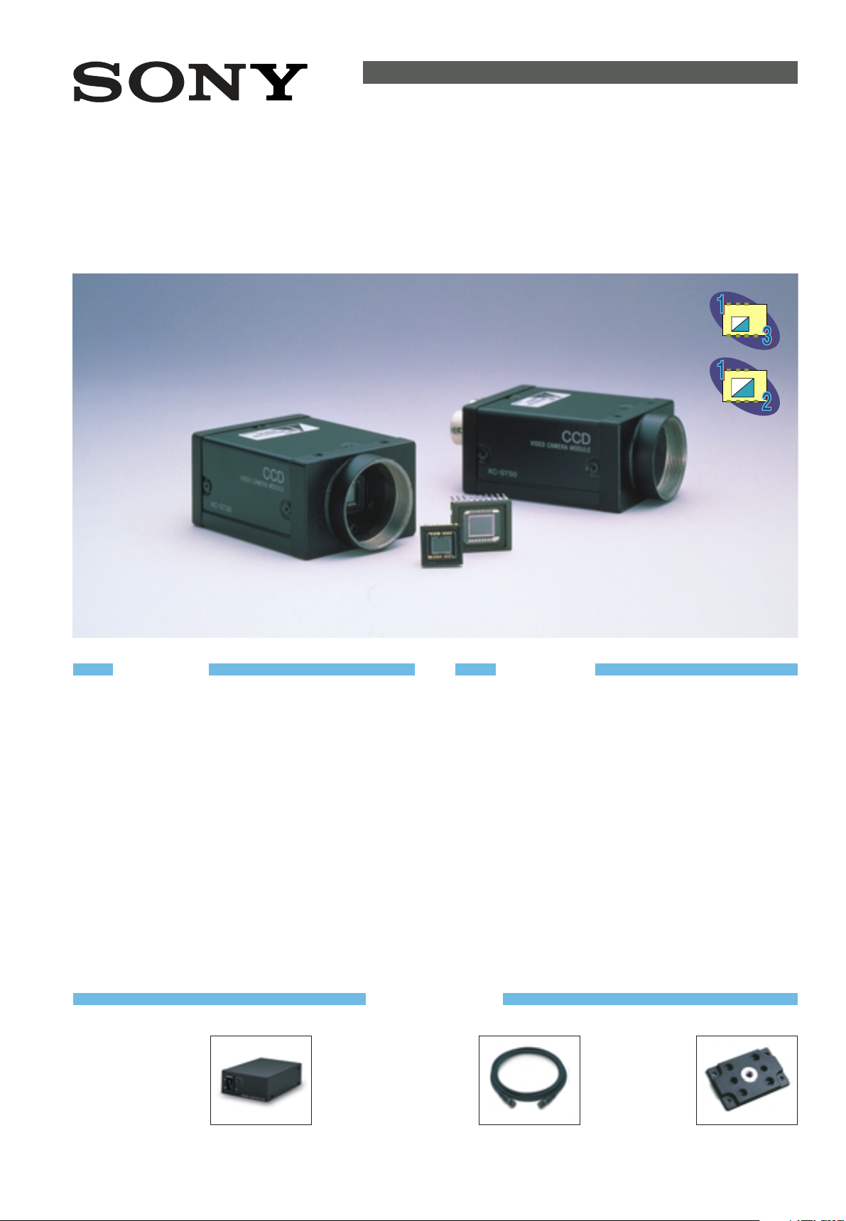
CCD B/W VIDEO CAMERA MODULE
XC-ST50/ST50CE
XC-ST30/ST30CE
Component / OEM
OUTLINE
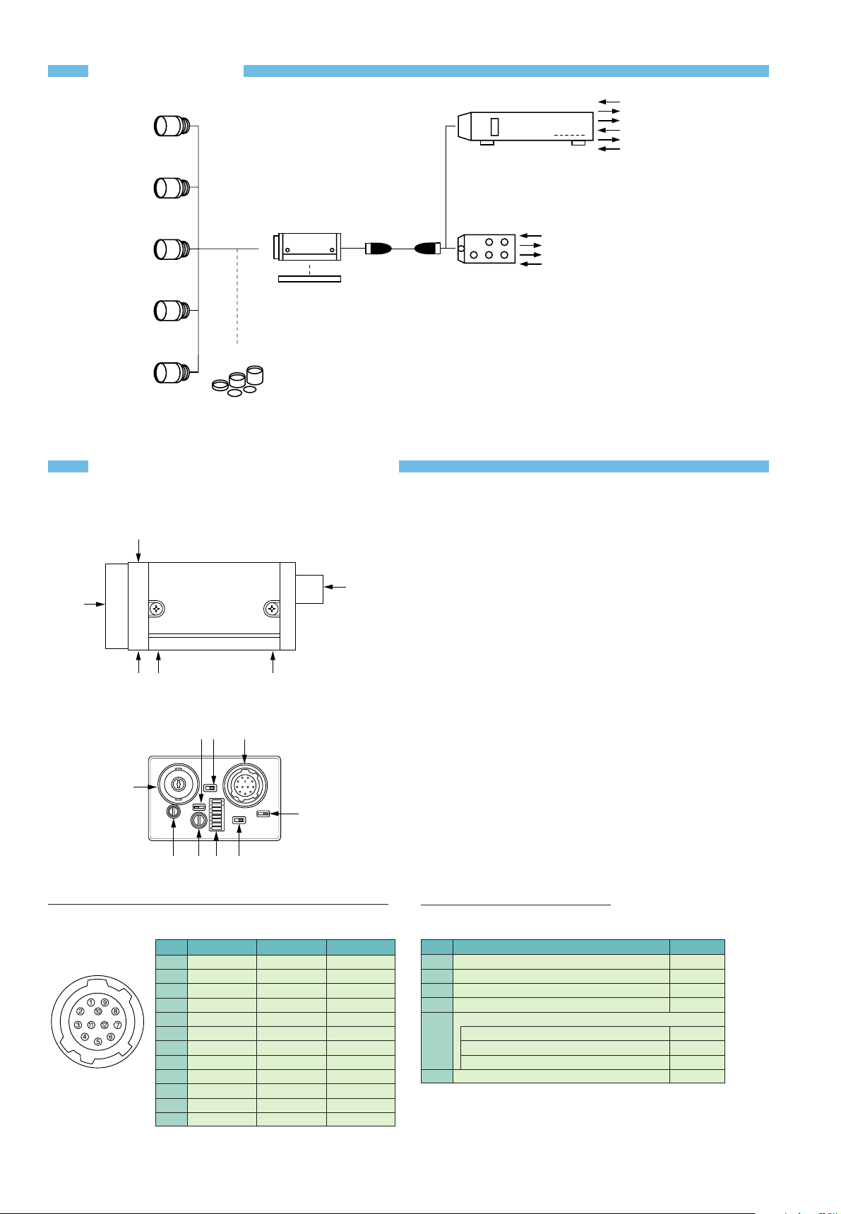
ACCESSORIES
Compact camera adaptor (CE standard)
DC-700/700CE
●
Compact, lightweight
●
Two video outputs
●
External sync IN/OUT
●
Trigger input/WEN output
●
New EIAJ standard 12 pin
assignment
●
Dimensions: 110(W) x 53(H) x 160(D) mm
FEATURES
● XC-ST50/50CE: 1/2 type IT CCD
● XC-ST30/30CE: 1/3 type IT CCD
● Small and lightweight: 44(W) x 29(H) x 57.5(D) mm, 110 g
● High sensitivity: 0.3 lx (F1.4)
● High S/N ratio: 60 dB (XC-ST50), 56 dB (XC-ST30)
● Electronic shutter function (1/100 to 1/10,000 s)
● Flexible trigger shutter functions
– simple trigger with internally generated HD/VD and Write
Enable (WEN)
– exposure control with switches or trigger pulse width
● Readout on command (with HD/VD input)
● 2:1 interlace/non-interlace
● Frame/field exposure
● Restart/Reset function
● Synchronization: internal/external (HD/VD, VS)
● High shock and vibration tolerance
12 pin camera cable (CE standard)
CCXC-12P02N (2m)
CCXC-12P05N (5m)
CCXC-12P10N (10m)
CCXC-12P25N (25m)
Tripod adaptor
VCT-ST70I
●
Isolated type
●
Approx. 14 g
●
Dimensions:
40(W) x 6(H) x 59(D) mm
The XC-ST50/ST50CE and XC-ST30/ST30CE incorporate
the latest CCD and signal processing technologies into
a compact black and white camera module. A new
external trigger design allows the electronic shutter
speed to be freely specified by the width of an external
trigger pulse or by a switch setting on the rear panel of
the camera. These cameras are also user-friendly, with
all switch settings located on the rear panel. Moreover,
the XC-ST50/ST50CE 1/2 type CCD and XC-ST30/ST30CE
1/3 type CCD models have the exact same dimensions,
simplifying space requirements and making it easy to
interchange them if necessary. These features, along
with high picture quality and high shock and vibration
tolerance make the
XC-ST50/ST50CE
and
XC-ST30/ST30CE
cameras ideal for demanding machine vision applications.
Page 2
CONNECTIONS
LO-77ERK
VCL-08YM
VCL-12YM
VCL-16YM
VCL-25YM
XC-ST30/CE
XC-ST50/CE
Tripod adaptor
VCT-ST70I
CCXC-12P02N
C mount lens
Extension ring kit
VCL-50YM
AC
VIDEO OUT
VS
*2
HD/VD
*1
TRIG
WEN
DC +12 V
VIDEO OUT
VS*
2
HD/VD*
1
Camera cable
Camera adaptor
DC-700/CE
New EIAJ standard 12 pin assignment
Junction box
JB-77
Trigger IN connector not available
CCXC-12P05N
CCXC-12P10N
CCXC-12P25N
*
1
: HD/VD cannot be simultaneously used with VS
*2: VS cannot be simultaneously used with HD/VD
LOCATION OF PARTS & OPERATION
4 5
2
1
3
2
3
A5B0 9
4
8
67
CCD
VIDEO CAMERA MODULE
XC-ST50
1 Lens mount (C mount)
A commercial C mount lens as well as
Sony standard lenses can be used.
2 Camera fixing reference hole
High-precision screw hole machined
on the lens mount surface.
3 Screw hole for tripod adaptor
installation (VCT-ST70I)
4 12 pin multi-connector
The 12 pin multi-connector is
connected to a DC IN/SYNC
(DC power/sync signal input)
5 BNC connector
Video out
6 Gamma correction
ON/OFF switchable
7 Internal/External
synchronization switch
In the EXT position, if there is no
external sync input, the internal sync is
activated inside the camera.
In this case, HD/VD signal is not output
through the 12 pin multi-connector.
8 Trigger polarity switch
The trigger polarity is selectable
(neg/pos polarity)
9 75 Ω termination switch
0 Dip switch
Dip switch 1 - 4: Shutter speed
Dip switch 5: FRAME/FIELD exposure
Dip switch 6 - 8: Normal shutter mode,
External trigger shutter
mode, restart/reset mode
A Gain switch
A: Image output at a fixed level of
image according to the brightness
of the subject. (Variable range: 0 to
18 dB)
F: Fixed gain 0 dB
M: gain (manual)
Factory setting: the variable gain is adjusted to
the fixed sensitivity for a
standard subject. When using
two or more XC-ST50/50CE,
XC-ST30/30CE cameras,
identical images of the same
subject can be attained.
B Gain control
The gain can be adjusted between 0 to
18 dB when the gain switch is set to "M".
Pin No. External HD/VD sync Internal HD/VD sync External VS sync
1 GND GND GND
2 +12 V +12 V +12 V
3 GND GND GND
4 VIDEO output VIDEO output VIDEO output
5 GND GND GND
6
External HD input Internal HD output
-
7*3External VD input Internal VD output
VS
8 GND GND GND
9
--10*4WEN output*2WEN output*2WEN output
11 TRIG input TRIG input TRIG input
12 GND GND GND
*3
: In restart/reset mode VD input is necessary
*4
: WEN output is only effective in EXT trigger shutter mode
No. Switch Factory setting
6 Gamma correction ON/OFF OFF
7 Internal/External sync EXT
8 Trigger polarity +
9 75 Ω termination ON
0 Dip switch
1·2·3·4: Shutter speed OFF
5: Field/Frame OFF
6·7·8:
normal shutter/EXT trigger shutter/restart reset
OFF
A GAIN FIX
● Rear Panel Factory settings
● Side
● 12 pin multi-connector
● Rear Panel
4 12 pin
multi-connector
Page 3

TRIGGER SHUTTER MODES
A new external trigger design allows the electronic shutter speed to be freely specified by the width of an external
trigger pulse or by a switch setting on the rear panel of the camera.
■ Shutter speed setting based on the trigger width
■ Shutter speed settings by dip switch control
Shutter speeds are set by dip switches 6,7,8 on the camera's rear panel. The width of the trigger pulse is irrelevant.
External trigger operation
Trigger
Video
output
WEN
output
Normal operation
more than 1/3 s
*
Non reset mode Ext sync (continuous HD/continuous VD input), or internal sync
External trigger operation
Trigger
Video
output
VD input
WEN
output
Normal operation
more than 1/3 s
*
Non reset mode Ext sync (continuous HD and single VD input)
External trigger operation
1-2H
Trigger
Video
output
WEN
output
Normal operation
*
Reset mode Only for Ext sync
more than 1/3 s
* When switching from Ext. trigger to regular operation the WEN pulse is output
Page 4

DIMENSIONS & REAR PANEL
SPECIFICATIONS
XC-ST50 XC-ST30 XC-ST50CE XC-ST30CE
Image device 1/2 type IT CCD 1/3 type IT CCD 1/2 type IT CCD 1/3 type IT CCD
Effective picture elements 768(H) x 494(V) 752(H) x 582(V)
Signal system EIAstandard CCIR standard
Horizontal frequency 15.734 kHz +/-1% 15.625 kHz +/-1%
Vertical frequency 59.94 Hz 50 Hz
Lens mount C mount
Flange back 17.526 mm
Sync system Internal / External (auto)
External Sync system HD / VD (2 ~ 5 Vp-p), VS
External Sync frequency Horizontal sync frequency +/- 1%
Jitter less than +/- 50 nsec
Scanning system 525 lines, 60 fields/s, 2:1 Interlaced 625 lines, 50 fields/s, 2:1 Interlaced
Video output 1.0 Vp-p, negative, 75 Ω unbalanced
Horizontal resolution 570 TV lines 560 TV lines
Sensitivity 400 lx, F8 (g compensation ON, 0 dB)
Minimum illumination 0.3 lx (F1.4, AGC ON, without IR cut filter)
S/N ratio 60 dB 56 dB 58 dB 54 dB
Gain AGC (0-18 dB) / Manual (0-18 dB) / Fixed (0 dB) Selectable
Gamma ON / OFF
Normal shutter 1/100 ~ 1/10,000 s 1/120 ~ 1/10,000 s
External trigger shutter 1/4 ~ 1/10,000 s 1/4 ~ 1/8,000 s
Power requirements DC12 V +/-10%
Power consumption 2.0 W 1.9 W 2.0 W 1.9 W
Dimensions 44(W) x 29(H) x 57.5(D) mm
Weight 110 g
Operation temp. /humidity -5˚C ~ +45˚C/20 ~ 80%
Storage temp./humidity -30˚C~ +60˚C/20 ~ 95%
Vibration 10 G (20 ~ 200 Hz)
Shock resistance 70 G
MTBF 70,600 hrs.
Regulations UL1492, FCC Class ADigital Device, CE (EN50081-2 + EN50082-2), AS4251.1 + AS4252.2
Supplied accessories Lens mount cap (1), Operating instructions (1)
CCD
VIDEO CAMERA MODULE
XC-ST50
57.5
50 ±0.513
26 ±0.3
29
4-M3 depth 4
(8)
44
65.5
13
26 ±0.3
2-M3 depth 4
XC-ST50/ST50CE
XC-ST30/ST30CE
(unit: mm)
● Sony Electronics Inc. (USA) HQ 1 Sony Drive Park Ridge, NJ 07656 (TEL:+1-800-686-7669)
http://www.sony.com/videocameras
● Sony of Canada Ltd. (CANADA) 115 Gordon Baker Rd, Toronto, Ontario M2H 3R6 (TEL:+1-416-499-1414) (FAX:+1-416-497-1774)
● Sony Broadcast & Professional Europe HQ 15, rue Floreal F-75831 Paris Cedex 17, France (TEL:+33-1-55-90-35-11) (FAX:+33-1-55-90-35-17)
http://www.pro.sony-europe.com
Germany Hugo-Eckener-Strasse 20 D-50829 Koln (TEL:+49-221-5966-322) (FAX:+49-221-5966-491)
France 15, rue Floreal F-75831 Paris Cedex 17 (TEL:+33-1-55-90-41-58) (FAX:+33-1-55-90-42-20)
UK The Heights, Brooklands, Weybridge, Surrey KT13 0XW (TEL:+44-990-331122) (FAX:+44-1932-817011)
Nordic Per Albin Hanssons vag 20 S-214 32 Malmo Sweden (TEL:+46-40-190-800) (FAX:+46-40-190-450)
Italy Via Galileo Galilei 40 I-20092 Cinisello Balsamo, Milano (TEL:+39-2-618-38-431) (FAX:+39-2-618-38-402)
©2000 Sony Corporation. All rights reserved.
Reproduction in whole or in part without written permission is prohibited.
Design and specifications are subject to change without notice.
http://www.sony.co.jp/ISP/
MK7494V1IW00JAN
IS-1108-A
Product Information
Document & Software
Information including product features and catalogs
Product document information and sample software downloads
Product information is available on the
ISP Home Page
Sample software
Command ListApplication Guide
Instruction Manual
Product catalog
http://www.sony.co.jp/ISP/
User’s Guide
XC-ST50/30
Click!
 Loading...