

Sony SSC-G203A-R User Manual
A-ECZ-100-01 (1)
ɞ
ɠɟ
OFF ON
1
2
3
5
6
7
8
9
10
4
ɣ
ɡ
ɢ
AB Version
Color Video Camera
Operating Instructions
Before operating the unit, please read this manual thoroughly and
retain it for future reference.
Mode d’emploi
Avant d’utiliser cet appareil, lisez attentivement le présent mode
d’emploi et conservez-le pour toute référence ultérieure.
SSC-G103/G203
SSC-G103A/G203A
SSC-G108/G208
http://www.sony.net/
2012 Sony Corporation Printed in U.S.A.
English
Owner’s Record
The model and serial numbers are located on the bottom.
Record these numbers in the spaces provided below.
Refer to these numbers whenever you call upon your Sony dealer regarding this
product.
Model No. Serial No.
WARNING
To reduce a risk of fire or electric shock, do not expose this
product to rain or moisture.
To avoid electrical shock, do not open the cabinet. Refer
servicing to qualified personnel only.
The apparatus shall not be exposed to dripping or splashing and no objects filled
with liquid, such as vases, shall be placed on the apparatus.
WARNING (for SSC-G108/G208 only)
The mains plug must be used to disconnect mains power.
Please ensure that the socket outlet is installed near the equipment and shall be
easily accessible.
WARNING
This installation should be made by a qualified service person and should
conform to all local codes.
CAUTION
The rating label is located on the bottom.
Power Supply
Caution for U.S.A. and Canada (for SSC-G103A/G203A only)
In the USA, this product shall be powered by a UL listed Class 2 Power Supply
Only.
In Canada, this product shall be powered by a CSA Certified Class 2 Power Supply
Only.
For customers in the U.S.A. (for SSC-G103A/G203A only)
This device complies with Part 15 of the FCC Rules. Operation is subject
to the following two conditions: (1) This device may not cause harmful
interference, and (2) this device must accept any interference received,
including interference that may cause undesired operation.
NOTE: This equipment has been tested and found to comply with the limits
for a Class A digital device, pursuant to Part 15 of the FCC Rules. These limits
are designed to provide reasonable protection against harmful interference
when the equipment is operated in a commercial environment. This equipment
generates, uses, and can radiate radio frequency energy and, if not installed and
used in accordance with the instruction manual, may cause harmful interference
to radio communications. Operation of this equipment in a residential area is
likely to cause harmful interference in which case the user will be required to
correct the interference at his own expense.
You are cautioned that any changes or modifications not expressly approved in
this manual could void your authority to operate this equipment.
All interface cables used to connect peripherals must be shielded in order to
comply with the limits for a digital device pursuant to Subpart B of Part 15 of FCC
Rules.
For customers in Canada (for SSC-G103A/G203A only)
This Class A digital apparatus complies with Canadian ICES-003.
Cet appareil numérique de la classe A est conforme à la norme NMB-003 du
Canada.
For the customers in Europe (for SSC-G103/G203/G108/G208 only)
The manufacturer of this product is Sony Corporation, 1-7-1 Konan, Minato-ku,
Tokyo, 108-0075 Japan.
The Authorized Representative for EMC and product safety is Sony Deutschland
GmbH, Hedelfinger Strasse 61, 70327 Stuttgart, Germany. For any service or
guarantee matters please refer to the addresses given in separate service or
guarantee documents.
For the customers in Europe, Australia and New Zealand (for
SSC-G103/G203/G108/G208 only)
WARNING
This is a Class A product. In a domestic environment, this product may cause
radio interference in which case the user may be required to take adequate
measures.
In the case that interference should occur, consult your nearest authorized Sony
service facility.
This apparatus shall not be used in the residential area.
ATTENTION
The electromagnetic fields at specific frequencies may influence the picture of
the unit.
Features
The color video camera is equipped with a 1/3 inch Super HAD CCD II* and also
has the following features:
High resolution
High sensitivity
Noise Reduction
Day/Night function allowing color/monochrome mode switching
Automatic white balance tracking and adjustment (ATW/PRO)
DC controlled auto-iris lens capability
Backlight compensation
Line lock function for synchronizing through AC power source
* Super HAD CCD IITM is a trademark of Sony Corporation.
Notes on Use
Power supply
The SSC-G103/G203 operates on either AC 24 V (50 Hz) or DC 12 V power.
The SSC-G103A/G203A operates on either AC 24 V (60 Hz) or DC 12 V power.
The SSC-G103/G103A/G203/G203A automatically detects the power.
- When connecting the transformer, be sure to connect each lead to the
appropriate terminal. Wrong connection may cause malfunction and/or
damage to the video camera.
- Ground the unit or an irregular voltage may be generated in the AC power
cable and may cause malfunction and/or damage to the video camera.
The SSC-G108/G208 must always be operated with an AC 220 V - 240 V (50 Hz)
power supply.
Handling of the unit
Be careful not to spill water or other liquids on the unit, or allow combustible or
metallic objects to fall inside the body. If used with a foreign object inside, the
camera is liable to fail, or be a cause of fire or electric shock.
Data and security
Always make a test recording, and verify that it was recorded successfully. SONY
WILL NOT BE LIABLE FOR DAMAGES OF ANY KIND INCLUDING, BUT NOT LIMITED
TO, COMPENSATION OR REIMBURSEMENT ON ACCOUNT OF FAILURE OF THIS
UNIT OR ITS RECORDING MEDIA, EXTERNAL STORAGE SYSTEMS OR ANY OTHER
MEDIA OR STORAGE SYSTEMS TO RECORD CONTENT OF ANY TYPE.
Personal information
The images taken by the system using this device can identify individuals
and thus they fall under “personal information” stipulated in the“ Act on the
Protection of Personal Information”. Please handle the video data appropriately
according to law.
Information recorded using this product may also be “personal information”.
Upon disposal, transfer, repair, or any other occasion where this product or
storage media is passed on to a third party, practice due care in its handling.
Operating or storage location
Do not shoot an extremely bright object (an illumination, the sun, etc.). Also,
avoid operating or storing the camera in the following locations, as these can be
a cause of a malfunction.
Extremely hot or cold places (Operating temperature: –10°C to +50°C [14°F to
122°F])
Exposed to direct sunlight for a long time, or close to heating equipment (e.g.,
near heaters)
Close to sources of strong magnetism
Close to sources of powerful electromagnetic radiation, such as radios or TV
transmitters
Locations subject to vibration or shock
Humid or dusty locations
Locations exposed to rain
Locations under the influence of fluorescent light or reflection of a window
Under an unsteady light (the image will flicker)
Where it is subject to moisture
Where it is subject to fumes and oil stains
Ventilation
To prevent heat buildup, do not block air circulation around the camera.
Transportation
When transporting the camera, repack it as originally packed at the factory or in
materials of equal quality.
Cleaning
Use a blower to remove dust from the lens.
Use a soft, dry cloth to clean the external surfaces of the camera. Stubborn
stains can be removed using a soft cloth dampened with a small quantity of
detergent solution, then wipe dry.
Do not use volatile solvents such as alcohol, benzene or thinners as they may
damage the surface finishes.
Other
When the iBLC switch is set to ON, “hunting” may occur, that is, the image may
get darker and lighter as the camera “hunts” for the optimum exposure level. If
hunting occurs, set the iBLC switch to OFF.
The focus may be less sharp under near infrared light than under visible light.
The best camera performance may not be obtained under near infrared light
due to the lens coating.
When the SHUTTER is set to AUTO, or the SHUTTER is set to FIX while the
shutter speed is being set, flicker may occur depending on ambient light.
Note on laser beams
Laser beams may damage the CCDs. If you shoot a scene that includes a laser beam,
be careful not to let a laser beam become directed into the lens of the camera.
In the event of any problems with the operation of the camera, contact your
Sony dealer.
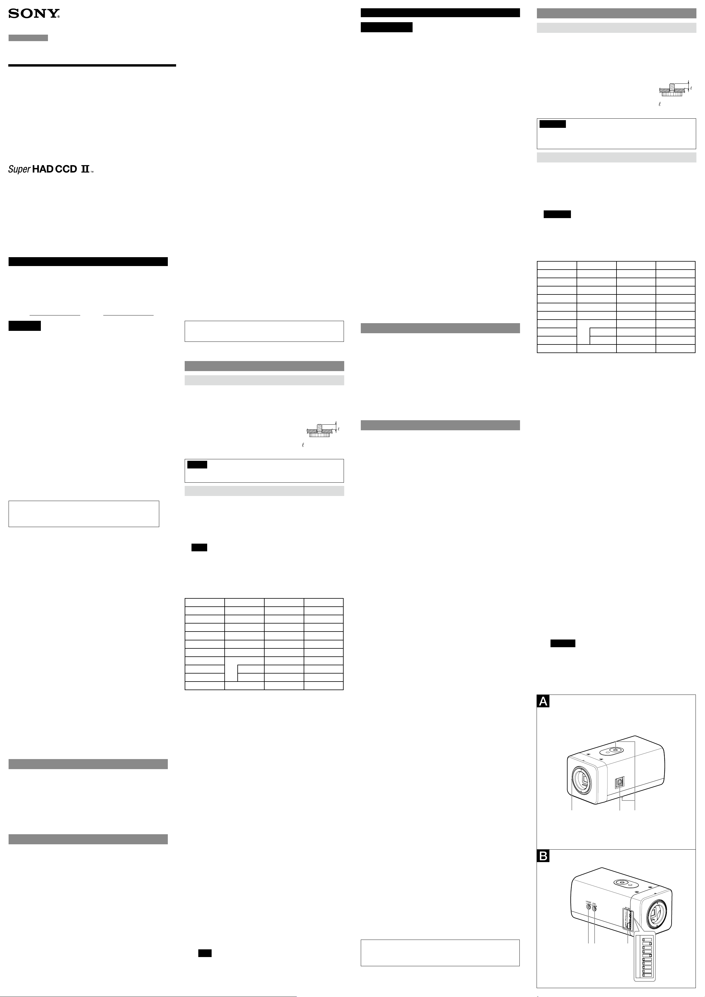
Location and Function of Part
Top/Front/Right/Bottom Side
Lens mount
Use to mount an appropriate CS-mount lens.
To use a C-mount type lens, attach the C-mount adaptor (not supplied).
Lens connector (4-pin socket)
Supplies power and control signals to an auto-iris lens (not supplied).
Tripod screws
The screw holes for attaching the tripod are located
on both the top and bottom of the camera. Use a
1/4"20 UNC screw to attach a tripod to the camera.
The tripod must be set up on a flat surface and
tightened firmly by hand.
Caution
Use the mounting screw whose length is 4.5 mm - 7 mm only. Use of other screws may
cause improper mounting and damage parts inside the camera.
Left Side
V PHASE (Vertical Phase) adjustment screw
Enable its function when the SYNC switch is set to LL.
If the picture rolls vertically, use the V PHASE adjustment screw to adjust
vertical phase until the picture is stable.
LEVEL adjustment screw
The LEVEL adjustment screw adjusts the DC lens brightness (image exposure)
away from the default position.
Notes
When the SHUTTER is set to AUTO, the LEVEL adjustment screw is not
effective.
When the MANUAL iris lens is installed, the LEVEL adjustment screw is not
effective.
Mode setting DIP switch
The following DIP switches are turned on if they have been set to the right
positions.
SW No. Switch OFF ON
1 SYNC INT LL
2 AGC OFF ON
3 iBLC OFF ON
4 ATR-Lite OFF ON
5 NR OFF ON
6 WB ATW PRO
7 D/N OFF AUTO
8 TIME LONG SHORT
9 LEVEL LOW HIGH
10 SHUTTER FIX AUTO
1: SYNC (Sync Lock) switch (Initial setting: INT)
Use this switch to set the camera synchronization mode to INT (Internal)
or LL (Line Lock).
When the camera power is DC 12 V, the camera is in the internal operation
mode regardless of the switch setting.
2: AGC (Automatic Gain Control) switch (Initial setting: ON)
Set this switch to ON to increase the gain of the video amplifier in low
light shooting conditions.
3: iBLC (Intelligent Backlight Compensation) ON/OFF switch (Initial
setting: OFF)
Use this switch to adjust the exposure to compensate for situations where
the subject is lit from behind.
4: ATR-Lite (Lite Adaptive Tone Reproduction) switch (Initial setting:
OFF)
When the switch is set to ON, the camera will adjust the tone
automatically in accordance to the difference between bright and dark.
5: NR (Noise Reduction) switch (Initial setting: ON)
When the switch is set to ON, the camera will automatically apply the
digital compensation to noise.
6: WB( White Balance) switch (Initial setting: ATW)
Choose the WB modes of the camera:
PRO (ATW-PRO): adjust the WB automatically to be closest to the image
you are viewing .
ATW: adjust the WB automatically to reproduce original colors of the
objects. This mode is especially effective in specific lights, such as sodium,
etc..
7: D/N (Day/Night) switch (Initial setting: OFF)
Choose the modes of D/N:
AUTO: Automatically switches between day and night mode when the
illumination falls below or exceeds the threshold level.
OFF: Day mode is always applied.
8: TIME (Day/Night time) switch (Initial setting: LONG)
Sets the time for switching Day/Night mode.
SHORT takes more than 2 seconds, and LONG takes more than 30 seconds.
9: LEVEL (Day/Night level) switch (Initial setting: LOW)
Sets the brightness of the object of when Day/Night mode switches.
When set to LOW, the camera will switch to night mode in a darker
environment than set to HIGH.
10: SHUTTER switch (Initial setting: FIX)
Use this switch to set the shutter mode.
AUTO: the shutter speed is automatically controlled according to exposure
level.
FIX: the shutter speed is fixed by the rear DIP switch setting. For details,
refer to “Setting of DIP switch for shutter speed” on the reverse side.
Note
When AUTO has been set, it will open the DC servo iris lens forcibly.
1/4”, 20 UNC
= 4.5 mm - 7 mm
(ISO standard) (with the
screws fastened)
(continued on the reverse side)
Français
AVERTISSEMENT
Afin de réduire les risques d’incendie ou d’électrocution, ne
pas exposer cet appareil à la pluie ou à l’humidité.
Afin d’écarter tout risque d’électrocution, garder le coffret
fermé. Ne confier l’entretien de l’appareil qu’à un personnel
qualifié.
L’appareil ne doit être exposé ni à des gouttes d’eau ni à des éclaboussures.
Aucun objet contenant du liquide, tel qu’un vase, ne doit être posé sur l’appareil.
AVERTISSEMENT (pour le modèle SSC-G108/G208
uniquement)
La fiche secteur de cet appareil doit être utilisée pour couper l’alimentation
secteur.
Veuillez vous assurer que la prise est installée à proximité de l’appareil et qu’elle
est facilement accessible.
AVERTISSEMENT
L’installation doit être effectuée par un technicien qualifié et se conformer à
toute la réglementation locale.
ATTENTION
L’étiquette indiquant la puissance nominale se trouve sous l’appareil.
Pour les clients au Canada (pour le modèle SSC-G103A/G203A
uniquement)
Cet appareil numérique de la classe A est conforme à la norme NMB-003 du
Canada.
Pour les clients en Europe (pour le modèle SSC-G103/G203/G108/G208
uniquement)
Le fabricant de ce produit est Sony Corporation, 1-7-1 Konan, Minato-ku, Tokyo,
108-0075 Japon.
Le représentant autorisé pour EMC et la sécurité des produits est Sony
Deutschland GmbH, Hedelfinger Strasse 61, 70327 Stuttgart, Allemagne.
Pour toute question concernant le service ou la garantie, veuillez consulter les
adresses indiquées dans les documents de service ou de garantie séparés.
Pour les clients en Europe, Australie et Nouvelle-Zélande (pour le
modèle SSC-G103/G203/G108/G208 uniquement)
AVERTISSEMENT
Il s’agit d’un produit de Classe A. Dans un environnement domestique, cet
appareil peut provoquer des interférences radio, dans ce cas l’utilisateur peut
être amené à prendre des mesures appropriées.
Si des interférences se produisent, contactez votre service après-vente agréé
Sony.
Ne pas utiliser cet appareil dans une zone résidentielle.
ATTENTION
Des champs électromagnétiques à des fréquences spécifiques peuvent avoir une
incidence sur l’image de cet appareil.
Caractéristiques
La caméra vidéo couleur est munie d’un capteur Super HAD CCD II*
1/3 pouces La caméra couleur vidéo et dispose également des fonctions
suivantes :
Haute résolution
Haute sensibilité
Réduction du bruit
Fonction jour/nuit permettant de basculer entre les modes couleur/
monochrome
Recherche et réglage automatiques de la balance des blancs (ATW/ATW-PRO)
Fonction d’objectif auto-iris CC
Compensation de contre-jour
Fonction de verrouillage de ligne pour une synchronisation avec la source
d’alimentation secteur
* Super HAD CCD IITM une marque commerciale de Sony Corporation.
Remarques sur l’utilisation
Alimentation
Le modèle SSC-G103/G203 fonctionne sous une tension de 24 V CA (50 Hz) ou
12 V CC.
Le modèle SSC-G103A/G203A fonctionne sous une tension de 24 V CA (60 Hz)
ou 12 V CC.
Le modèle SSC-G103/G103A/G203/G203A détecte automatiquement la
tension adéquate.
- Lorsque vous raccordez le transformateur, assurez-vous de raccorder chaque
fil à la borne appropriée. Tout raccordement incorrect risque de provoquer
un dysfonctionnement ou d’endommager la caméra vidéo.
- Mettez l’appareil à la terre. Dans le cas contraire, une tension inadéquate
risque d’être générée dans le câble d’alimentation, ce qui peut provoquer un
dysfonctionnement ou endommager la caméra vidéo.
Le modèle SSC-G108/G208 doit toujours être utilisé avec une source
d’alimentation comprise entre 220 V et 240 V CA (50 Hz).
Manipulation de l’appareil
Veillez à ne pas renverser d’eau ou d’autres liquides sur l’appareil ni laisser des
substances combustibles ou des objets métalliques pénétrer dans le boîtier.
L’utilisation de la caméra alors que des corps étrangers se trouvent à l’intérieur
risque de provoquer une défaillance, un incendie ou des décharges électriques.
Données et sécurité
Effectuez toujours un essai d’enregistrement pour vérifier que l’enregistrement
s’est fait correctement. Sony n’assumera pas de responsabilité pour les
dommages de quelque sorte qu’ils soient, incluant mais ne se limitant pas
à la compensation ou au remboursement, suite au manquement de cet
appareil ou de son support d’enregistrement, de systèmes de mémoire
extérieurs ou de tout autre support ou système de mémoire à enregistrer un
contenu de tout type.
Informations personnelles
Les images prises par le système qui utilise cet appareil peuvent identifier les
individus et sont donc considérées comme « informations personnelles », tel que
le décrit l’« Acte de protection des informations personnelles ». Nous vous prions
d’utiliser les données vidéo conformément à la réglementation en vigueur.
Les informations enregistrées avec cet appareil sont également considérées
comme « informations personnelles ». Si vous mettez cet appareil au rebut, le
transférez, le faites réparer ou le cédez à un tiers, veillez à prendre les mesures
nécessaires pour que ces informations ne soient pas utilisées de façon
frauduleuse.
Lieu d’utilisation ou de rangement
Ne filmez pas un objet extrêmement brillant (un éclairage, le soleil, etc.). Par
ailleurs, afin d’éviter tout dysfonctionnement, évitez d’utiliser ou d’entreposer la
caméra dans les lieux suivants.
Lieux extrêmement chauds ou froids (température de fonctionnement : –10°C
à +50°C [14°F à 122°F])
Lieux exposés aux rayons directs du soleil de façon prolongée ou à proximité
d’un appareil de chauffage (radiateurs, par exemple)
Près de puissantes sources magnétiques
Proches de sources de puissantes radiations électromagnétiques, comme des
transmetteurs de radio ou de télévision
Lieux soumis à de fortes vibrations ou à des chocs
Lieux humides ou poussiéreux
Lieux exposés à la pluie
Lieux soumis à l’influence de lumière fluorescente ou au reflet d’une fenêtre
Sous un éclairage non stable (l’image risque de vaciller)
Dans un endroit exposé à l’humidité
Dans un endroit soumis à des émanations et aux taches d’huile
Aération
Pour prévenir toute surchauffe interne, n’entravez pas la circulation de l’air autour
de la caméra.
Transport
Pour le transport de la caméra, replacez-la dans son emballage d’origine ou dans
un emballage de même qualité.
Nettoyage
Utilisez une soufflante pour dépoussiérer l’objectif.
Utilisez un chiffon doux et sec pour nettoyer les surfaces externes de la
caméra. Pour éliminer les taches tenaces, utilisez un chiffon doux légèrement
imprégné d’une solution détergente, puis essuyez.
N’utilisez pas de solvants puissants tels que de l’alcool, du benzène ou des
diluants, car vous risquez d’endommager le fini des surfaces de l’appareil.
Divers
Lorsque le commutateur iBLC est réglé sur ON, une oscillation horizontale
peut se produire. En d’autres termes, l’image peut s’assombrir et s’éclaircir
lorsque la caméra recherche le niveau d’exposition optimal. Si ce phénomène
se produit, réglez le commutateur iBLC sur OFF.
La mise au point risque d’être moins nette sous une lumière infrarouge qu’à la
lumière du jour.
Il est possible que les performances de la caméra ne soient pas optimales sous
une lumière infrarouge en raison du revêtement de l’objectif.
Lorsque le mode d’obturation est réglé sur AUTO, ou sur FIX lors du réglage
de la vitesse d’obturation, l’image risque de vaciller en fonction de l’éclairage
ambiant.
Remarque sur les faisceaux laser
Les faisceaux laser peuvent endommager les CCD. Si vous lmez une scène
comportant un faisceau laser, veillez à ce que celui-ci ne soit pas dirigé vers
l’objectif de l’appareil.
Si vous rencontrez des problèmes dans le cadre de l’utilisation de cette caméra,
consultez votre revendeur Sony.
Emplacement et fonction des pièces
Côtés supérieur/avant/droit/inférieur
Monture de l’objectif
Sert à la fixation d’un objectif à monture CS approprié.
Pour utiliser un objectif à monture C, fixez l’adaptateur de monture C (non
fourni).
Connecteur d’objectif (prise à 4 broches)
Transmet l’alimentation et les signaux de commande à un objectif à
diaphragme automatique (non fourni).
Vis de trépied
Les orifices des vis de trépied sont situés sur les parties
supérieure et inférieure de la caméra. Utilisez des vis
de type 1/4" 20 UNC pour fixer un trépied à la caméra.
Vous devez installer le trépied sur une surface plane et
le tenir fermement dans votre main.
Précaution
Utilisez une vis de montage d’une longueur de 4,5 mm - 7 mm uniquement.
L’utilisation d’autres vis peut entraîner une installation incorrecte et
endommager des pièces à l’intérieur de la caméra.
Côté gauche
Vis de réglage V PHASE (phase verticale)
Activez cette fonction lorsque le SYNC commutateur est réglé sur LL.
Si l’image penche verticalement, utilisez la vis de réglage V PHASE pour régler
la phase verticale jusqu’à ce que l’image soit stable.
Vis de réglage LEVEL
La vis de réglage LEVEL permet de régler la luminosité de l’objectif CC
(exposition de l’image).
Remarques
Lorsque le mode d’obturation est défini sur AUTO, la vis de réglage LEVEL
n’est pas effective.
Lorsque l’objectif à iris manuel est installé, la vis de réglage LEVEL n’est pas
effective.
Commutateur DIP de réglage de mode
Les commutateurs DIP suivants sont activés s’ils ont été réglés sur la position
correcte.
SW No. Commutateur OFF ON
1 SYNC INT LL
2 AGC OFF ON
3 iBLC OFF ON
4 ATR-Lite OFF ON
5 NR OFF ON
6 WB ATW PRO
7 D/N OFF AUTO
8 TIME LONG SHORT
9 LEVEL LOW HIGH
10 SHUTTER FIX AUTO
1 : Commutateur SYNC (Verrouillage de synchronisation) (réglage
initial : INT)
Ce commutateur permet de régler la synchronisation de la caméra sur le
mode INT (Interne) ou LL (Verrouillage de ligne).
Lorsque l’alimentation de la caméra est de 12 V CC, la caméra est en mode
de fonctionnement interne, quelle que soit la position du commutateur.
2 : Commutateur AGC (Contrôle de gain automatique) (réglage initial :
ON)
Utilisez ce commutateur pour augmenter le gain de l’amplificateur vidéo
lorsqu’il est réglé sur ON.
3 : Commutateur ON/OFF iBLC (Correction intelligente du rétroéclairage)
(réglage initial : OFF)
Utilisez ce commutateur pour régler l’exposition afin de compenser les
sujets à contre-jour.
4 : Commutateur ATR-Lite (Reproduction de ton adaptative) (réglage
initial : OFF)
Lorsque ce commutateur est réglé sur ON, la caméra ajuste
automatiquement la tonalité en fonction des différences entre les tons
lumineux et sombres.
5 : Commutateur NR (Réduction du bruit) (réglage initial : ON)
Lorsque ce commutateur est réglé sur ON, la caméra effectue
automatiquement une compensation numérique du bruit.
6 : Commutateur WB (Balance des blancs) (réglage initial : ATW)
Permet de sélectionner le mode WB de la caméra parmi les suivants :
PRO (ATW-PRO) : ajuste automatiquement la balance des blancs pour
qu’elle soit la plus fidèle possible à l’image que vous visionnez.
ATW : ajuste automatiquement la balance des blancs de façon
à reproduire les couleurs originales des objets. Ce mode est
particulièrement efficace lors de l’utilisation de lampes spécifiques,
notamment celles au sodium.
7 : Commutateur D/N (Jour/Nuit) (réglage initial : OFF)
Permet de sélectionner le mode D/N :
AUTO : commute automatiquement les modes diurne et nocturne lorsque
l’illumination dépasse le niveau seuil ou tombe en dessous.
OFF : le mode diurne est toujours appliqué.
8 : Commutateur TIME (Durée jour/nuit) (réglage initial : LONG)
Règle la durée de commutation du mode Diurne/Nocturne.
SHORT dure plus de 2 secondes et LONG plus de 30 secondes.
9 : Commutateur LEVEL (Niveau jour/nuit) (réglage initial : LOW)
Règle la luminosité de l’objet lorsque le mode Diurne/Nocturne commute.
Lorsqu’il est réglé sur LOW, la caméra passe au mode nocturne dans un
environnement plus sombre que lorsqu’il est réglé sur HIGH.
10 : Commutateur SHUTTER (Niveau jour/nuit) (réglage initial : FIX)
Utilisez ce commutateur pour régler le mode d’obturation.
AUTO : la vitesse d’obturation est automatiquement contrôlée en fonction
du niveau d’exposition.
FIX : le paramètre du commutateur DIP arrière fixe la vitesse d’obturation.
Pour plus de détails, reportez-vous à la rubrique « Réglage du
commutateur DIP correspondant à la vitesse d’obturation » au verso.
Remarque
Si vous avez sélectionné AUTO, l’objectif à iris servo CC s’ouvre de manière
forcée.
U1/4”, 20 UNC
= 4,5 mm - 7 mm
(Norme ISO)
(avec vis serrées)
(suite au verso)
Monitor screen
Vertical tails shown on the image
Bright object (e.g., strong spotlight,
strong reflected light, flashlight, the sun)
Ecran du moniteur
Traînées verticales sur l’image
Objet brillant (éclairage directionnel
intense, lumière réfléchie intense,
flashs, soleil, etc.)
SSC-G103/G203/G103A/G203A SSC-G108/G208
ɥɤ ɤ
ɨ
ɥ
ɧ
ɦ ɦ
ɤ ɥ
ɧ
ɦ
3
1
2
4
2
1
2
3
ʓʖ
ʔ
ʕ
ʓ
ʕ
ʖ
ʔ
Rib (If the cable is thick, cut this off.)
Pin 4 Video signal control Ground
Pin 2 Video signal control Not used
Pin 1 Video signal control Power supply (+DC 9 V, 50 mA)
Pin 3 Video signal control Video signal
Taquet (Si le câble est épais, coupez-le.)
Broche 4 Signal de commande vidéo Masse
Broche 2 Signal de commande vidéo Non utilisé
Broche 1 Signal de commande vidéo Alimentation (+9 V CC, 50 mA)
Broche 3 Signal de commande vidéo Signal vidéo
SSC-G103/G203/G103A/G203A
SSC-G108/G208
Lens / Objectif
4 mm or less /
4 mm ou moins
Rib / Taquet
Lens Connector (not supplied) /
Connecteur pour objectif (non fourni)
DC control Drive – (Ground)
DC control Control +
DC control Control –
DC control Drive +
Commande CC Drive – (Masse)
Commande CC Control +
Commande CC Control –
Commande CC Drive +
C-mount adaptor /
Adaptateur pour
monture C
C-mount type lens /
Objectif à monture C
Fall-prevention rope
(not supplied) /
Câble anti-chute
(non fournie)
Screw (not supplied) /
Vis (non fournie)
English
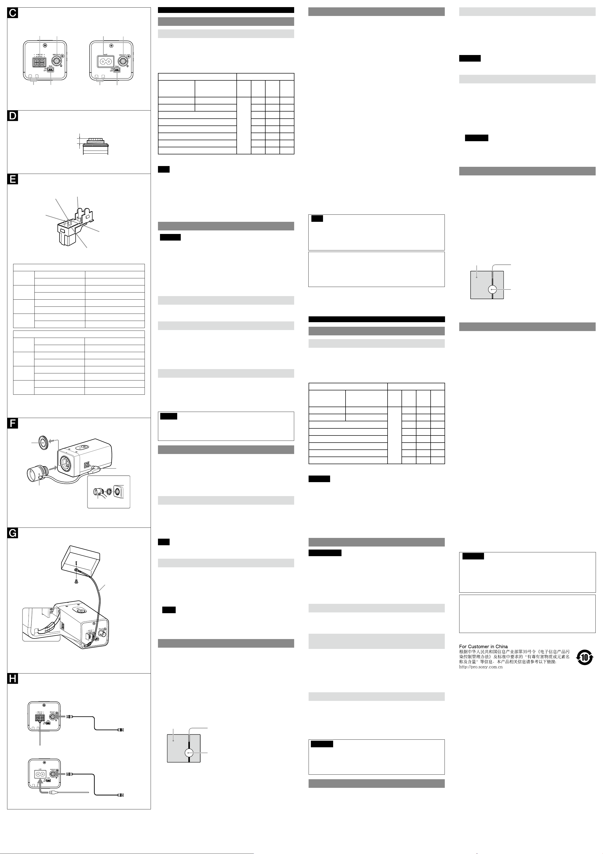
Preparations
Rear
Fall-prevention rope mounting hole
When installing the camera on a ceiling or a wall. Be sure to secure a
fall-prevention rope (not supplied) to this hole for safety.
Setting of DIP switch for shutter speed
The following DIP switches are turned on if they have been set to the top
positions.
SHUTTER SPEED (sec) SW No.
PAL
(SSC-G103/G203/
G108/G208)
1/50 1/60
1/100 1/120 OFF OFF ON
1/150 OFF ON OFF
1/200 OFF ON ON
1/250 ON OFF OFF
1/300 ON OFF ON
1/500 ON ON OFF
1/1000 ON ON ON
There are 4 DIP switches on the rear, three of which are functional.
These switches provide 8 different shutter speeds.
Note
To enable these DIP switches, the SHUTTER switch should be set to FIX.
VIDEO OUT (composite video signal output) connector (BNC type)
DC 12 V/AC 24 V (50 Hz) (power input) terminal (DC 12 V ±10% /AC 24 V
±10%) (for SSC-G103/G203 only)
DC 12 V/AC 24 V (60 Hz) (power input) terminal (DC 12 V ±10% /AC 24 V
±10%) (for SSC-G103A/G203A only)
Power inlet (AC 220 V - 240 V, 50 Hz) (for SSC-G108/G208 only)
NTSC
(SSC-G103A/G203A)
1 2 3 4
OFF OFF OFF
N/A
Installation
WARNING
If you attach the camera in the height such as the wall or the ceiling, etc.,
entrust the installation to an experienced contractor or installer.
If you install the camera on the ceiling, ensure that the ceiling is strong
enough to withstand the weight (20 Kg) of the camera plus the bracket
and then install the camera securely. If the ceiling is not strong enough, the
camera may fall and cause serious injury.
To prevent the camera from falling, make sure to attach the rope (not
supplied).
If you attach the camera to the ceiling, check periodically, at least once a
year, to ensure that the connection has not loosened. If conditions warrant,
make this periodic check more frequently.
Suitable lens
The lens must be a CS-mount type of less than 1 kg. The protrusion behind the
CS mounting surface must be 4 mm or less.
To use a C-mount type lens, use the C-mount adaptor (not supplied).
Installation of an Auto Iris Lens Connector
Install the lens connector (not supplied) when using an Auto Iris Lens.
This installation should be done only by qualified service personnel or system
installers. A lens connector is not included with this camera package.
1 Cut the iris control cable at the edge of the lens connector to remove the
existing lens connector and then remove the outer cable cover as shown in
the diagram on the left.
2 Solder the lens cable to the pins of the lens connector.
Fitting the lens
1 Unscrew the lens mount cap.
2 Screw in the lens, and turn it until it is secured.
To use a C-mount type lens
Attach the C-mount adaptor (not supplied) before screwing in the lens.
3 Insert the lens plug in the LENS connector.
When fitting a manual-iris lens, skip 3.
Caution
Keep the lens mount cap on the camera when it is not attached the lens.
Check the lens mount
Check the lens mount at least once a year to ensure it has not become loose.
If conditions warrant, make this periodic check more frequently.
Installing the camera
ATTENTION
If installing the camera on the ceiling, be sure it is secure. If not securely installed,
the camera may fall and injury may occur.
If the camera is installed on the ceiling using equipment such as a bracket,
housing and motored swivel base (pan/tilt), do the following:
Use tripod screws and securely tighten them with a driver. Order the tripod
screws (Sony Part No. 3-174-693-02) from your nearest Sony dealer.
Install the tripod adapter on a flat surface.
Attaching the fall-prevention rope
When you install the camera on a ceiling or a high position, be sure to attach the
fall-prevention rope (not supplied) to prevent the camera from falling.
Thread the fall-prevention rope through the hole on the rear of the camera, and
then fix it to the junction box on the ceiling or wall with a screw (not supplied),
as in the illustration.
For details about the fall-prevention rope, please consult the store of
purchase or an authorized Sony dealer.
Note
Take care not to short-circuit the power terminal or the cable with the rope when
you attach it.
Connecting the Camera
Connect the video cable to the VIDEO OUT connector.
Connect the video cable to the VIDEO IN connector of a video monitor,
etc.
Connect to the appropriate power source using a power cable.
SSC-G108/G208: to AC 220 V - 240 V (50 Hz) power source
SSC-G103/G203: to a DC 12 V, or an AC 24 V (50 Hz) power source
SSC-G103A/G203A: to a DC 12 V, or an AC 24 V (60 Hz) power source
Notes
Be sure to input only the proper voltage to the power terminal of the
camera.
Be sure to push the power cable all the way in.
75-ohm coaxial cable.
Typical CCD phenomenon
The following phenomena that may appear in images are specific to CCD
(Charge Coupled Device) image sensors. They do not indicate malfunctions.
White flecks
Although the CCD image sensors are produced with high-precision technologies,
fine white flecks may be generated on the screen in rare cases, caused by cosmic
rays, etc.
This is related to the principle of CCD image sensors and is not a malfunction.
The white flecks especially tend to be seen in the following cases:
when operating at a high environmental temperature
when you have raised the gain (sensitivity)
when using the slow shutter
Vertical smear
When an extremely bright object, such as a strong spotlight or flashlight, is
being shot, vertical tails may be produced on the screen, or the image may
be distorted.
Aliasing
When fine patterns, stripes, or lines are shot, they may appear jagged or
flicker.
Specifications
Image device 1/3 inch interline transfer Super HAD CCD II
Effective picture elements SSC-G103/G203/G108/G208: 752 (H) × 582 (V) PAL
SSC-G103A/G203A: 768 (H) × 494 (V) NTSC
Lens mount CS-mount
C-mount is available when the C-mount adaptor (not
supplied) is used.
Signal system SSC-G103/G203/G108/G208: PAL color system
SSC-G103A/G203A: NTSC color system
Synchronization system internal/line lock
Horizontal resolution 540 TV lines
Minimum illumination 0.04 lx (15IRE, F1.2)
Video output 1.0 Vp-p, 75 ohms, negative sync
Video S/N 55 dB (AGC OFF, WEIGHT ON)
Electronic shutter SSC-G103/G203/G108/G208:
1/50, 1/100, 1/150, 1/200, 1/250, 1/300, 1/500,
1/1000 (sec)
SSC-G103A/G203A:
1/60, 1/120, 1/150, 1/200, 1/250, 1/300, 1/500,
1/1000 (sec)
White balance ATW/PRO selectable
Automatic gain control (AGC)
ON/OFF switchable
Power requirements SSC-G103/G203: AC 24 V (50 Hz) / DC 12 V
SSC-G103A/G203A: AC 24 V (60 Hz) / DC 12 V
SSC-G108/G208: AC 220 V - 240 V (50 Hz)
Power consumption SSC-G103/G103A: 1.4 W
SSC-G203/G203A: 1.6 W
SSC-G108: 1.8 W
SSC-G208: 2 W
Operating temperature –10°C to +50°C (14°F to 122°F)
Operating humidity 20% to 80%
Storage temperature –40°C to +60°C (–40°F to +140°F)
Storage humidity 20% to 95%
Mass SSC-G103/G103A: Approx. 250 g (8.8 oz)
SSC-G203/G203A/G108: Approx. 255 g (9.0 oz)
SSC-G208: Approx. 260 g (9.2 oz)
Dimensions 117.6 mm × 63.2 mm × 57.2 mm (4
2 1/ inches × 2 3/ inches) (Projecting part not included)
(w/h/d)
Supplied accessories Operating instructions (this document) (1)
Power cable (1) (for SSC-G108/G208 only)
Lens mount cap (1)
Design and specifications are subject to change without notice.
Note
Always verify that the unit is operating properly before use. SONY WILL
NOT BE LIABLE FOR DAMAGES OF ANY KIND INCLUDING, BUT NOT LIMITED
TO, COMPENSATION OR REIMBURSEMENT ON ACCOUNT OF THE LOSS OF
PRESENT OR PROSPECTIVE PROFITS DUE TO FAILURE OF THIS UNIT, EITHER
DURING THE WARRANTY PERIOD OR AFTER EXPIRATION OF THE WARRANTY,
OR FOR ANY OTHER REASON WHATSOEVER.
3
/ inches ×
Recommendation of Periodic Inspections
In case using this device over an extended period of time, please have it
inspected periodically for safe use.
It may appear awless, but the components may have deteriorated over
time, which may cause a malfunction or accident.
For details, please consult the store of purchase or an authorized Sony
dealer.
Français
Préparatifs
Arrière
Orifice de montage du câble anti-chute
Lors de l’installation de la caméra au plafond ou sur mur, veillez à attacher le
cable anti-chute (non fourni) à cet orifice pour plus de sécurité.
Réglage du commutateur DIP correspondant à la vitesse d’obturation
Les commutateurs DIP suivants sont activés s’ils ont été réglés sur les
positions supérieures.
SHUTTER SPEED (sec) SW No.
PAL
(SSC-G103/G203/
G108/G208)
1/50 1/60
1/100 1/120 OFF OFF ON
1/150 OFF ON OFF
1/200 OFF ON ON
1/250 ON OFF OFF
1/300 ON OFF ON
1/500 ON ON OFF
1/1000 ON ON ON
4 commutateurs DIP se trouvent à l’arrière, dont trois sont fonctionnels.
Ces commutateurs fournissent 8 vitesses d’obturation différentes.
Remarque
Pour activer ces commutateurs DIP, le commutateur SHUTTER doit être réglé sur
FIX.
Connecteur VIDEO OUT (sortie du signal vidéo composite) (type BNC)
Borne DC 12 V/AC 24 V (50 Hz) (entrée alimentation) (12 V CC ±10% /24 V
CA ±10%) (pour le modèle SSC-G103/G203 uniquement)
Borne DC 12 V/AC 24 V (60 Hz) (entrée alimentation) (12 V CC ±10% /24 V
CA ±10%) (pour le modèle SSC-G103A/G203A uniquement)
Entrée d’alimentation (220 V - 240 V CA, 50 Hz) (pour le modèle
SSC-G108/G208 uniquement)
NTSC
(SSC-G103A/G203A)
1 2 3 4
OFF OFF OFF
N/A
Installation
AVERTISSEMENT
Faites appel à un spécialiste pour une installation de la caméra en hauteur (au
plafond ou au mur par exemple).
Si vous installez la caméra au plafond, vérifiez que ce dernier peut supporter
le poids (20 kg) de la caméra et de son support ; puis fixez solidement la
caméra. Si le plafond n’est pas assez solide, la caméra risque de tomber et
d’entraîner des blessures.
Pour éviter que la caméra ne tombe, veillez à fixer le câble d’acier (non fourni).
Si vous fixez la caméra au plafond, vérifiez l’installation régulièrement
(au moins une fois par an) afin de contrôler la tenue des vis. Si nécessaire,
procédez à cette vérification plus souvent.
Objectif compatible
L’objectif doit être à monture CS et peser moins de 1 kg. La protubérance située
derrière la surface de la monture CS doit être inférieure ou égale à 4 mm.
Pour utiliser un objectif à monture C, utilisez l’adaptateur de monture C (non
fourni).
Installation d’un connecteur d’objectif à
diaphragme automatique
Installez le connecteur pour objectif (non fourni) lors de l’utilisation d’un objectif
à iris automatique.
Cette opération doit être effectuée uniquement par du personnel ou un
installateur qualifié. Le connecteur d’objectif n’est pas fourni avec cette caméra.
1 Coupez le câble de commande du diaphragme au bord du connecteur
d’objectif afin de retirer le connecteur d’objectif existant, puis retirez la
protection extérieure du câble comme illustré sur le schéma à gauche.
2 Soudez le câble de l’objectif aux broches du connecteur d’objectif.
Montage de l’objectif
1 Dévissez le bouchon de monture d’objectif.
2 Vissez l’objectif et tournez jusqu’à ce qu’il se verrouille.
Pour utiliser un objectif à monture C
Installez le connecteur pour objectif (non fourni) lors de l’utilisation d’un
objectif à iris automatique.
3 Insérez la fiche d’objectif dans le connecteur LENS.
Si vous utilisez un objectif à diaphragme manuel, passez l’étape 3.
Précaution
Laissez le capuchon de la monture d’objectif sur la caméra lorsqu’il n’est pas
fixé à l’objectif.
Vérifiez la monture d’objectif
Vérifiez la monture d’objectif au moins une fois par an afin de vous assurer
qu’elle tient bien. Si nécessaire, procédez à cette vérification plus souvent.
Installation de la caméra
ATTENTION
Si vous installez la caméra au plafond, assurez-vous qu’elle est bien fixée. Si elle
n’est pas fixée solidement, il se peut que la caméra tombe et blesse quelqu’un.
Si la caméra est installée au plafond à l’aide d’éléments tel qu’un support de
montage, un boîtier et une base pivotante motorisée (panoramique ou à
basculement), suivez les recommandations suivantes :
Utilisez des vis de trépied et serrez-les bien avec un tournevis. Commandez les
vis de trépied (N° de pièce Sony 3-174-693-02) chez votre revendeur Sony le
plus proche.
Installez l’adaptateur de trépied sur une surface plane.
Fixation du câble anti-chute
Lorsque vous installez la caméra sur le toit ou sur une surface en hauteur, veillez
à fixer le câble d’acier antichute (non fourni) afin d’éviter que la caméra tombe et
se brise.
Faites passer le cable anti-chute à travers l’orifice situé à l’arrière de la caméra,
puis fixez-le à la boîte de jonction au plafond ou sur le mur avec une vis (non
fournie), comme indiqué dans l’illustration.
Pour plus d’informations sur le cable anti-chute, contactez le magasin qui vous a
vendu la caméra ou un revendeur Sony agréé.
Remarque
Veillez à ne pas court-circuiter la borne ou le câble d’alimentation électrique avec
le câble lorsque vous fixez celui-ci.
Connexion de la caméra
Connectez le câble vidéo au connecteur VIDEO OUT.
Connectez le câble vidéo au connecteur VIDEO IN d’un moniteur vidéo,
etc.
Raccordez la caméra à la source d’alimentation adaptée à l’aide d’un
cordon d’alimentation.
SSC-G108/G208 : vers une source d’alimentation 220 V - 240 V CA (50 Hz)
SSC-G103/G203 : vers une source d’alimentation 12 V CC ou 24 V CA (50 Hz)
SSC-G103A/G203A : vers une source d’alimentation 12 V CC ou 24 V CA
(60 Hz)
Remarques
Veillez à alimenter la borne d’alimentation de la caméra avec la tension
appropriée uniquement.
Veillez à bien insérer le cordon d’alimentation.
Câble coaxial de 75 ohms.
Phénomène typique des CCD
Les phénomènes suivants qui peuvent apparaître dans les images sont
particuliers aux capteurs d’images CCD (Charge Coupled Device). Ils ne signalent
pas une anomalie.
Taches blanches
Bien que les capteurs CCD soient fabriqués à l’aide de technologies de haute
précision, il arrive rarement que des petites taches blanches apparaissent sur
l’écran, celles-ci sont causées par les rayons cosmiques, etc.
Cet effet est dû à la technologie des capteurs d’images CCD et ne signale pas une
anomalie.
Les taches blanches sont surtout visibles dans les cas suivants :
Lors du fonctionnement à haute température ambiante
Lorsque vous avez augmenté le gain (la sensibilité)
Lors de l’utilisation de l’obturateur lent
Bande verticale
Lorsqu’un objet très lumineux est filmé, comme un projecteur ou un flash, il
arrive que des bandes verticales apparaissent sur l’écran, ou que l’image soit
déformée.
Distorsion
Lorsque des lignes ou des motifs précis sont filmés, il arrive qu’ils soient déformés
ou qu’ils clignotent.
Spécifications
Système d’image Capteur Super HAD CCD II de transfert interligne
Eléments d’image effectifs SSC-G103/G203/G108/G208 : 752 (H) × 582 (V ) PAL
SSC-G103A/G203A : 768 (H) × 494 (V) NTSC
Monture de l’objectif Monture CS
La monture C est disponible lorsque vous utilisez
Système de signal SSC-G103/G203/G108/G208 : Système couleur PAL
SSC-G103A/G203A : Système couleur NTSC
Système de synchronisation Verrouillage interne/ligne
Résolution horizontale 540 lignes TV
Eclairement minimum 0,04 lx (15IRE, F1,2)
Sortie vidéo 1,0 Vc-c, 75 ohms, sync négative
Rapport signal/bruit vidéo 55 dB (fonction AGC désactivée, PONDÉRATION
Obturateur électronique SSC-G103/G203/G108/G208 :
Balance des blancs Compatible ATW/PRO
Réglage automatique du gain (AGC)
Commutable ON/OFF
Alimentation SSC-G103/G203 : 24 V CA (50 Hz) / 12 V CC
SSC-G108/G208 : 220 V - 240 V CA (50 Hz)
Consommation électrique SSC-G103/G103A : 1,4 W
SSC-G108 : 1,8 W
SSC-G208 : 2 W
Température d’utilisation –10°C à +50°C (14°F à 122°F)
Humidité d’utilisation 20% à 80%
Température de stockage –40°C à +60°C (–40°F à +140°F)
Humidité de stockage 20% à 95%
Poids SSC-G103/G103A : Environ 250 g (8,8 oz)
SSC-G208 : Environ 260 g (9,2 oz)
Dimensions 117,6 mm × 63,2 mm × 57,2 mm (4
Accessoires fournis Mode d’emploi (le présent document) (1)
Câble d’alimentation (1) (pour le modèle
Capuchon du support de fixation de l’objectif (1)
La conception et les spécifications sont sujettes à modification sans préavis.
Remarque
Vérifiez toujours que l’appareil fonctionne correctement avant l’utilisation.
SONY N’ASSUMERA PAS DE RESPONSABILITÉ POUR LES DOMMAGES DE
QUELQUE SORTE QU’ILS SOIENT, INCLUANT MAIS NE SE LIMITANT PAS À
LA COMPENSATION OU AU REMBOURSEMENT, À CAUSE DE LA PERTE DE
PROFITS ACTUELS OU FUTURS SUITE À LA DÉFAILLANCE DE CET APPAREIL,
QUE CE SOIT PENDANT LA PÉRIODE DE GARANTIE OU APRÈS SON
EXPIRATION, OU POUR TOUTE AUTRE RAISON QUELLE QU’ELLE SOIT.
Recommandations pour les inspections périodiques
En cas d’utilisation de cet appareil pendant une période prolongée, veillez
à son entretien périodique pour la sécurité.
Il peut sembler sans défaut, mais il est possible que les composants
se soient détériorés avec le temps, ce qui peut provoquer un
dysfonctionnement ou un accident.
Pour plus d’informations, consultez le magasin où vous avez acheté
l’appareil ou un revendeur Sony agréé.
de1/3 pouces
l’adaptateur de monture C (non fourni).
activée)
1/50, 1/100, 1/150, 1/200, 1/250, 1/300, 1/500,
1/1000 (sec)
SSC-G103A/G203A :
1/60, 1/120, 1/150, 1/200, 1/250, 1/300, 1/500,
1/1000 (sec)
SSC-G103A/G203A : 24 V CA (60 Hz) / 12 V CC
SSC-G203/G203A : 1,6 W
SSC-G203/G203A/G108 : Environ 255 g (9,0 oz)
3
1
2
/ pouces × 2 3/ pouces) (pièce saillante non
comprise) (l/h/p)
SSC-G108/G208 uniquement)
/ pouces ×
 Loading...