

Page 1
3-113-376-02 (1)
Color Video Camera
Operating Instructions
Before operating the unit, please read this manual thoroughly and
retain it for future reference.
SSC-CD75/CD75P
SSC-CD77/CD77P
2007 Sony Corporation Printed in China
English
Owner’s Record
The model and serial numbers are located on the bottom. Record these
numbers in the spaces provided below.
Refer to these numbers whenever you call upon your Sony dealer
regarding this product.
Model No.
WARNING
To avoid electrical shock, do not open the cabinet. Refer
servicing to qualified personnel only.
WARNING
This installation should be made by a qualified service person and should
conform to all local codes.
WARNING
A readily accessible disconnect device shall be incorporated in the
building installation wiring.
WARNING (for Installers only)
Instructions for installing the equipment on the ceiling or the wall:
After the installation, ensure the connection is capable of supporting four
times the weight of the equipment downwards.
CAUTION
The rating label is located on the bottom.
Power Supply
Caution for U.S.A. and Canada
The SSC-CD75/CD77 operates on 24V AC or 12V DC.
The SSC-CD75/CD77 automatically detects the power.
Use a Class 2 power supply which is UL Listed (in the U.S.A) or CSAcertified (in Canada).
Caution for other countries
The SSC-CD75/75P/CD77/77P operates on 24V AC or 12V DC.
The SSC-CD75/75P/CD77/77P automatically detects the power.
CAUTION
After incorporating the heater unit, the rated power of the camera will be
16 W.
Ensure the power source is capable of providing the total power.
For customers in the U.S.A.
This device complies with Part 15 of the FCC Rules. Operation is
subject to the following two conditions: (1) This device may not cause
harmful interference, and (2) this device must accept any interference
received, including interference that may cause undesired operation.
NOTE: This equipment has been tested and found to comply with the limits for a
Class A digital device, pursuant to part 15 of the FCC Rules. These limits are
designed to provide reasonable protection against harmful interference when the
equipment is operated in a commercial environment. This equipment generates,
uses, and can radiate radio frequency energy and, if not installed and used in
accordance with the instruction manual, may cause harmful interference to radio
communications. Operation of this equipment in a residential area is likely to
cause harmful interference in which case the user will be required to correct the
interference at his own expense.
You are cautioned that any changes or modifications not expressly approved
in this manual could void your authority to operate this equipment.
All interface cables used to connect peripherals must be shielded in order
to comply with the limits for a digital device pursuant to Subpart B of Part
15 of FCC Rules.
For Customers in Canada
This Class A digital apparatus complies with Canadian ICES-003.
Cet appareil numérique de la classe A est conforme à la norme NMB-003
du Canada.
For Customers in Eurpoe
The manufacturer of this product is Sony Corporation, 1-7-1 Konan,
Minato-ku Tokyo, Japan.
The Authorized Representative for EMC and product safety is Sony
Deutschland GmbH, Hedelfinger Strasse 61, 70327 Stuttgart, Germany.
For any service or guarantee matters please refer to the addresses given
in separate service or guarantee documents.
For customers in other countries
WARNING
This is a Class A product. In a domestic environment, this product may
cause radio interference in which case the user may be required to take
adequate measures.
In the case that interference should occur, consult your nearest
authorized Sony service facility.
This apparatus shall not be used in the residential area.
ATTENTION
The electromagnetic fields at specific frequencies may influence the
picture of the unit.
Features
This is a dome-shaped color video camera for which the 1/3 type Super
HAD CCD® (SSC-CD75/CD75P) or SuperExwave® (SSC-CD77/CD77P)
has been adopted. It has the following features:
• IP 66* sealed enclosure (sturdy and weatherproof structure) suitable for
outdoor installation
• Manual setting of the camera direction – panning, tilting and rotating
• Vari-focal auto iris lens as standard equipment. The focal length of the
lens is from 2.8 mm to 10 mm.
• High quality CCD and clear dome cover enable high sensitivity.
• Backlight compensation through the center measurement.
• Automatic white balance tracking and adjustment (ATW/ATW-PRO)
• 24 V AC / 12 V DC power supply system
• Line lock function (24 V AC)
• Day/Night function automatically switches between color and
monochrome modes. You can control this function through an external
source when connecting the supplied DN cable. (SSC-CD77/CD77P)
• YT-HU75 Heater Unit (optional) allows you to operate this unit in low
temperature environments down to –40 °C (–40 °F). (24 V AC only /
except cold starting)
• Super HAD CCD® is a registered trademark of Sony Corporation.
• Super Exwave® is a registered trademark of Sony Corporation.
* IP66 is a protection grade provided under JIS and IEC.
Serial No.
• Close to sources of strong magnetism
• Close to sources of powerful electromagnetic radiation, such as radios
or TV transmitters
• Locations subject to vibration or shock
• Dusty locations
• Locations under the influence of fluorescent light or reflection of a
window
• Under an unsteady light (the image will flicker.)
Ventilation
To prevent heat buildup, do not block air circulation around the camera.
Transportation
When transporting the camera, repack it as originally packed at the
factory or in materials of equal quality.
Cleaning
• Use a blower to remove dust from the lens.
• Use a soft, dry cloth to clean the external surfaces of the camera.
Stubborn stains can be removed using a soft cloth dampened with a
small quantity of detergent solution, then wipe dry.
• Do not use volatile solvents such as alcohol, benzene or thinners as
they may damage the surface finishes.
To install the camera outdoors
Attach the dome casing securely to the unit casing.
Make sure you seal the locations listed below with sealant (e.g. silicon
sealant) to prevent moisture from getting inside the casing.
– Camera installation holes (4)
– Conduit holes (side/bottom)
Note on laser beams
Laser beams may damage a CCD. You are cautioned that the surface of a
CCD should not be exposed to laser beam radiation in an environment
where a laser beam device is used.
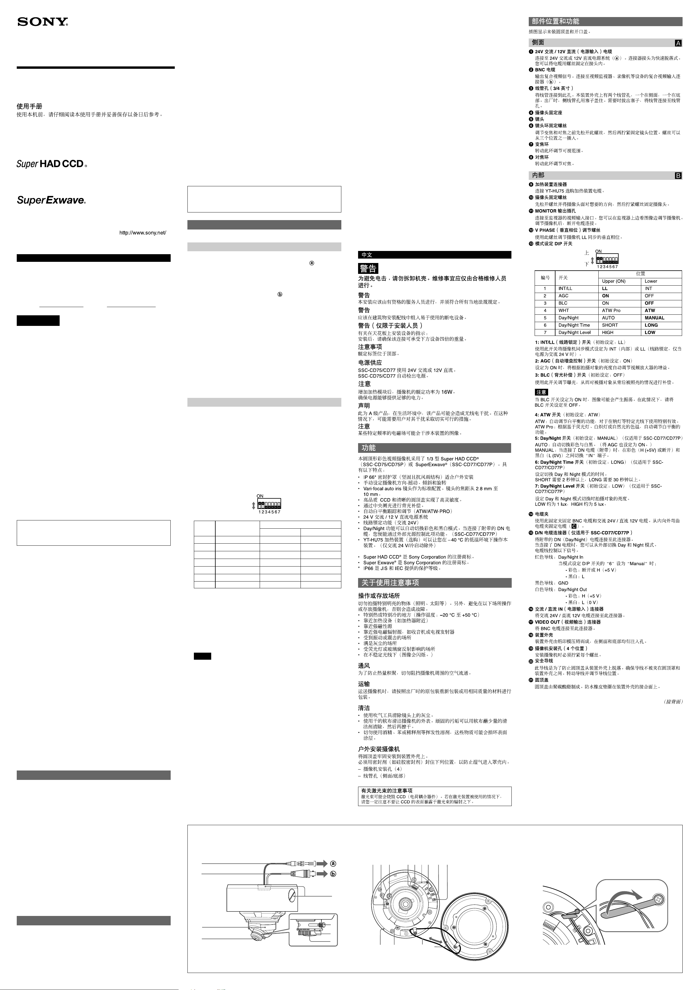
Location and Function of Part
The figure shows the camera without the dome casing and slit cover.
qf Cable clamp
Secure the BNC cable and AC 24V / DC 12V cable with this clamp.
Curl the cable clamp upward from inner side to fix the cables (C).
qg D/N cable connector (SSC-CD77/CD77P only)
Connect the supplied D/N (Day/Night) cable to this connecter.
When the D/N cable is connected, you can switch Day and Night
modes from outside.
The wires of the cable control the following signals.
Red wire: Day/Night In
When the "6" of Mode setting DIP switch is set to "Manual";
- Color: Open or H (+5 V)
- Black and White: L
Black wire: GND
White wire: Day/Night Out
- Color: H (+5 V)
- Black and White: L (0 V)
qh AC / DC IN (power input) connector
Connect an AC 24V / DC 12V cable to this connector.
qj VIDEO OUT (Video out) connector
Connect the BNC cable to this connector.
qk Unit casing
The unit casing is made of die-cast aluminum and has conduit holes
on the side and at the bottom.
ql Camera installation holes (4 positions)
Make sure to tighten the screws securely when installing the camera.
w; Safety cord
This cord prevents the dome casing from falling off the unit casing.
Make sure that the cord does not get caught between the dome casing
and the unit casing. Rotate the cord and adjust the position of the cord.
wa Dome casing
The dome cover is made of polycarbonate. A waterproof rubber gasket
is provided on the joint surface to the unit casing.
(continued on the reverse side)
Side A
1 24V AC/12V DC (power input) cable
Connect to a 24V AC or 12V DC power supply system ( ). The
connector tip is a quick-disconnect type. You can screw the cables in
the tip.
2 BNC cable
Outputs a composite video signal. Connect to a composite video input
connector of a video monitor, VCR, etc ( ).
3 Conduit holes (3/4 inch)
Connect a pipe to this hole. There are two conduit holes on the unit
casing, one on the side and one at the bottom. The cover plug is
installed in the side conduit hole at the factory. Remove the plug as
needed and connect the pipe to the hole.
4 Camera head holder
5 Lens
6 Lens ring fixing screw
Loosen this screw before adjusting the zoom and focus, then tighten it
to fix the lens position. The screw can be inserted at one of three
points.
7 Zoom ring
Turn this ring to adjust the field of view.
8 Focus ring
Turn this ring to adjust the focus.
Inside B
9 Heater unit connector
Connect the cable of the optional YT-HU75 Heater Unit.
0 Camera head fixing screw
First loose the screw and face the camera head to the desired
direction, then tighten the screw to fix it.
qa MONITOR out jack
Connect to a video input connector of a monitor. You can adjust the
camera while looking at the image on the monitor. After adjusting the
camera, disconnect the cable.
qs V PHASE (vertical phase) adjustment screw
Use this screw to adjust the vertical phase of cameras synchronized
by LL.
qd Mode setting DIP switch
Upper
Lower
Position
Lower
INT
OFF
OFF
ATW
MANUAL
LONG
LOW
1
2
3
4
5
6
7
Switch
INT/LL
AGC
BLC
WHT
Day/Night
Day/Night Time
Day/Night Level
Upper (ON)
LL
ON
ON
ATW Pro
AUTO
SHORT
HIGH
No.
1: INT/LL (line lock) switch (Initial setting: LL)
Use this switch to set the camera synchronization mode to INT
(internal) or LL (line lock, Only when the power is AC 24 V).
2: AGC (automatic gain control) switch (Initial setting: ON)
Set to ON to adjust the gain of the video amplifier automatically
according to the brightness of the object.
3: BLC (backlight compensation) switch (Initial setting: OFF)
Use this switch to adjust the exposure to compensate for situations
where the subject is lit from behind.
Notes
When BLC switch is set to ON, a hunting may be generated due to a
picture. In this case, set BLC switch to OFF.
4: ATW switch (Initial setting: ATW)
ATW: Automatic adjusting function of the white balance, effective for
use under special light like a sodium lamp.
ATW Pro: Automatic adjusting function of the white balance according
to the color temperature based on a fluorescent light, incandescent
lighting, or natural light.
5: Day/Night switch (Initial setting: MANUAL) (SSC-CD77/CD77P
only)
AUTO: Switches color and black-and-white automatically. (Set AGC
also to ON.)
MANUAL: Switches “IN” terminal between color (H (+5V) or open) and
black-and-white (L (0V)) when the DN cable (supplied) is connected.
6: Day/Night Time switch (Initial setting: LONG) (SSC-CD77/CD77P
only)
Sets the time for switching Day and Night mode.
SHORT takes more than 2 seconds, and LONG takes more than 30
seconds.
7: Day/Night Level switch (Initial setting: LOW) (SSC-CD77/CD77P
only)
Sets the brightness of the object of when Day and Night mode
switches.
LOW is approximately 1 lux and HIGH is approximately 5 lux.
AB
1
2
3
9ql0qa qs qg qhqfqd qj
C
Notes on Use
Operating or storage location
Do not shoot an extremely bright object (an illumination, the sun, etc.).
Also, avoid operating or storing the camera in the following locations, as
these can be a cause of a malfunction.
• Extremely hot or cold places (Operating temperature: –20 °C to
+50 °C [–4 °F to 122 °F])
• Close to heating equipment (e.g., near heaters)
4
5
6
7
8
qk
w; wa
Page 2
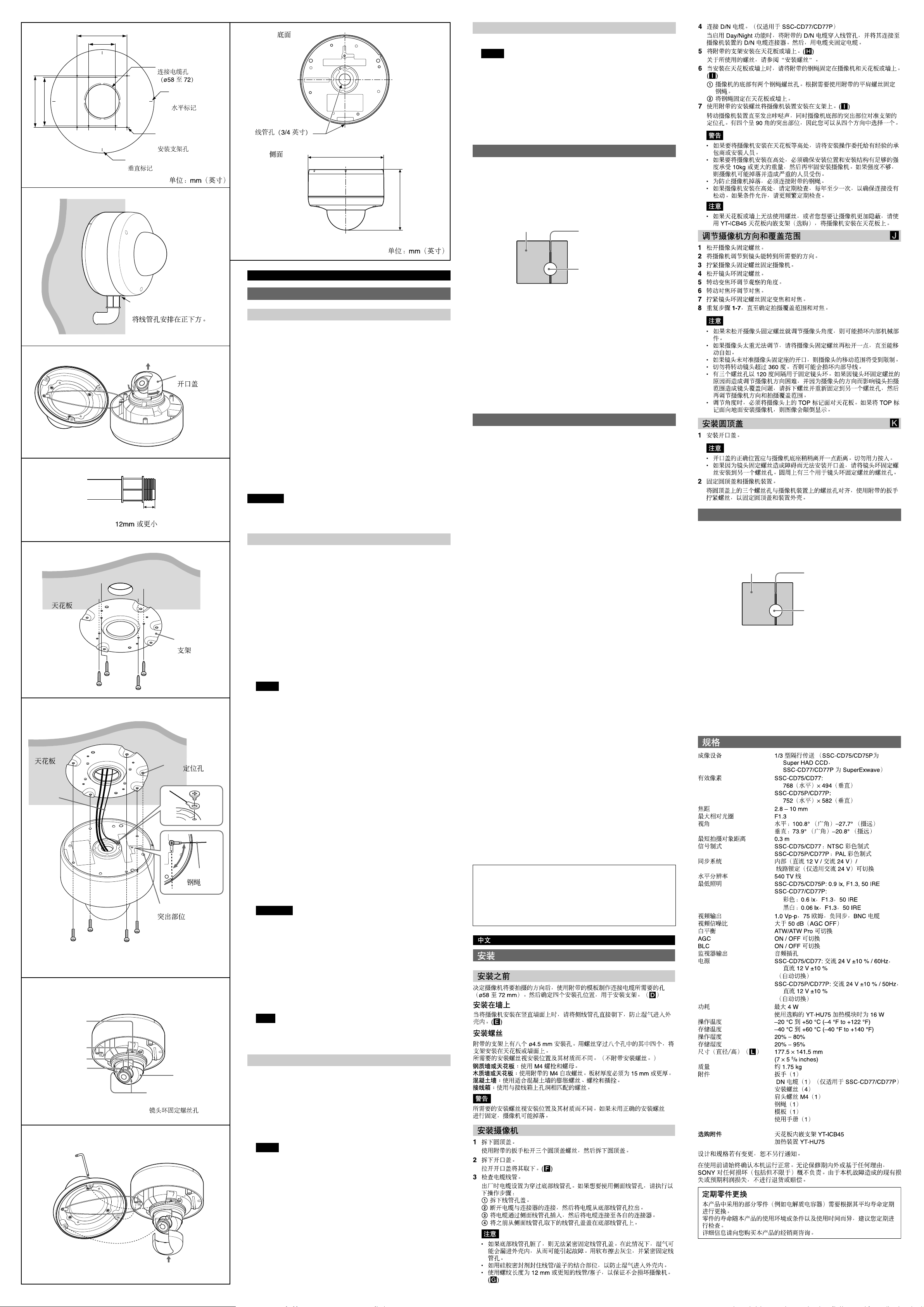
D
3
E
)
)
8
32
/
/
9
85.7 (3
83.5 (3
85.7 (3 3/8)
13
46 (1
/16)
Unit: mm (inches)/
Hole for the
connecting cables
ø58 to 72
(2 3/8 to 2 7/8)/
Hole for
installing the
bracket/
Vertical marker/
Horizontal
marker/
L
Bottom/
Conduit hole (3/4 in.)/
Side/
English
ø177.5 (7)
)
8
/
5
141.5 (5
Unit: mm (inches)/
Attaching the Dome Casing K
1 Attach the slit cover.
Notes
• The proper position of the slit cover is slightly apart from the camera
mount. Do not push in by force.
• If you cannot attach the slit cover because the barrier of the lens
ring fixing screw prevents it, attach the lens ring fixing screw to
another screw hole. There are three screw holes for the lens ring
fixing screw on the concentric circle.
2 Fix the dome casing and the camera unit.
Align the three screw holes on the dome casing with those on the
camera unit, and tighten the screws with the supplied wrench to
secure the dome casing and unit casing.
Typical CCD Phenomena
The following phenomena may appear on the monitor screen while you
are using a CCD color video camera. These phenomena stem from the
high sensitivity of the CCD image sensors, and do not indicate a fault
within the camera.
Vertical smear
A “smear” may appear to extend vertically from very bright subjects, as
shown below.
Video monitor screen
Pale vertical smear
Very bright subject (such as
an electric lamp,
fluorescent lamp, sunlight,
or strong reflected light)
F
G
H
I
Wire rope
J
K
Ceiling/
Ceiling/
1, 3
4, 7
Installation
Position the conduit hole
directly below./
Slit cover/
12mm (1/2 in.) or less/
Bracket/
Positioning
Hole/
Wire rope/
Projection/
5
6
2
Lens ring fixing
screw holes/
Before Installation
After deciding the direction in which the camera will shoot, make the
required hole (ø 58 to 72 mm (2 3/8 to 2 7/8 inches) ) for the connecting
cables using the supplied template. Then decide the four mounting hole
positions to install the bracket. (D)
Installing on the wall
When you install the camera on a wall lengthwise, position the side
conduit hole directly below to prevent moisture from getting inside the
casing. (E)
Mounting screws
The supplied bracket is provided with eight ø 4.5 mm ( 3/16 inch) mounting
holes. Install the bracket on a ceiling or wall with screws through these
four of the eight holes.
The required mounting screws differ depending on the installation location
and its material. (Mounting screws are not supplied.)
Steel wall or ceiling: Use M4 bolts and nuts.
Wood wall or ceiling: Use the supplied M4 tapping screws. The panel
thickness must be 15 mm ( 5/8 inch) or more.
Concrete wall: Use appropriate anchors, bolts and plugs for concrete
walls.
Junction box: Use screws to match the holes on the junction box.
WARNING
The required mounting screws differ depending on the installation location
and its material. If you do not secure the camera with the appropriate
mounting screws, the camera may fall off.
Installing the Camera
1 Remove the dome casing.
Loosen the three dome casing screws with the supplied wrench, and
remove the dome casing.
2 Remove the slit cover.
Remove it expanding the slit cover. (F)
3 Check the conduit of the cables.
The cables are set up at the factory to pass through the bottom conduit
hole. If you want to use the side conduit hole, perform the following
steps:
1 Remove the conduit hole cover.
2 Disconnect the cables from the connectors, and pull them out from
the bottom conduit hole.
3 Insert the cables through the side conduit hole, and connect the
cables to their respective connectors.
4 Attach the conduit hole cover that was removed from the side
conduit hole to the bottom conduit hole.
Notes
• If the bottom conduit hole is dirty, the conduit hole cover cannot be
fixed firmly. In this case, moisture may leak into the casing and this
may cause a malfunction. Wipe off the dust with a soft cloth, and fix
the conduit hole cover firmly.
• Cover the joint part of the pipe/cover with silicon sealant, etc. to
prevent moisture from getting inside the casing.
• Use a pipe/plug with a thread length of 12 mm (1/2 in.) or less so that
it does not damage the camera. (G)
4 Connect the D/N cable. (SSC-CD77/CD77P only)
When you make Day/Night function active, feed the supplied D/N
cable through the conduit hole, and connect it to the D/N cable
connector of the camera unit. Then, secure it with the cable clamp.
5 Install the supplied bracket on the ceiling or wall. (H)
Refer to “Mounting screws” for screws to be used.
6 When installing on a ceiling or wall, fix the supplied wire rope to the
camera and the ceiling or wall. (I)
1 There are two screw holes for wire rope on the bottom of the
camera. Fix the wire rope with the supplied shoulder screw as
required.
2 Fix the wire rope to the ceiling or wall.
7 Attach the camera unit to the bracket with the supplied mounting
screws. (I)
Turn the camera unit to click and fix one of the projections on the
bottom of the camera to the positioning hole of the bracket. There are
four projections with an angle of 90 degrees, so you can select one of
four directions.
WARNING
• If you want to install the camera at a height such as on a ceiling,
entrust the installation to an experienced contractor or installer.
• If you install the camera at a height, ensure that the installation
location and its material are strong enough to withstand a weight of
20 kg (44 lb 1 oz) or more, and then install the camera securely. If
they are not strong enough, the camera may fall and cause serious
injury.
• To prevent the camera from falling, be sure to attach the supplied
wire rope.
• If you install the camera at a height, check periodically, at least once
a year, to ensure that the connection has not loosened. If conditions
warrant, perform this periodic check more frequently.
Note
If you cannot use screws on a ceiling or wall, or if you want to make
the camera less conspicuous, use the YT-ICB45 in-ceiling bracket
(optional) with which you can mount the camera on the ceiling.
Adjusting the Camera Direction and Coverage
1 Loosen the camera head fixing screw.
2 Adjust the camera to turn the lens in the desired direction.
3 Tighten the camera head fixing screw to fix the camera.
4 Loosen the lens ring fixing screw.
J
This phenomenon is common to CCD imaging elements using an interline
transfer system, and is caused when electric charge induced by infrared
radiation deep within the photo sensor is transferred to the resistors.
Aliasing
When shooting fine stripes, straight lines or similar patterns, the lines may
become slightly jagged.
Blemishes
A CCD image sensor consists of an array of individual picture elements
(pixels). A malfunctioning sensor element will show up
as a single pixel blemish in the image. This is generally not a problem.
White speckles
When you shoot a poorly illuminated object at a high temperature, small
white dots may appear all over the entire screen image.
Specifications
Image device 1/3 type interline transfer (Super HAD CCD
Effective picture elements SSC-CD75/CD77:
Focal length 2.8 to 10 mm
Maximum relative aperture
View angle Horizontal: 100.8° (wide) – 27.7° (tele)
Minimum object distance
Signal system SSC-CD75/CD77: NTSC color system
Synchronization system Internal (DC 12 V/AC 24 V)/
Horizontal resolution 540 TV lines
Minimum illumination SSC-CD75/CD75P: 0.9 lx, F1.3, 50 IRE
Video output 1.0 Vp-p, 75 ohms, negative sync, BNC cable
Video S/N ratio More than 50 dB (AGC OFF)
White balance ATW/ATW Pro switchable
AGC ON / OFF switchable
BLC ON / OFF switchable
Monitor output Phono jack
Power supply SSC-CD75/CD77: 24 V AC ±10 % / 60Hz,
Power consumption 4 W max.
Operating temperature –20 °C to +50 °C (–4 °F to +122 °F)
Storage temperature –40 °C to +60 °C (–40 °F to +140 °F)
Operating humidity 20% to 80%
Storage humidity 20% to 95%
Dimensions (diameter/height) (L)
Mass Approx. 1.75 kg (3 lb 14 oz)
Supplied accessories Wrench (1), D/N cable (SSC-CD77/CD77P
Optional accessories In-ceiling bracket YT-ICB45
Design and specifications are subject to change without notice.
Always verify that the unit is operating properly before use. SONY WILL
NOT BE LIABLE FOR DAMAGES OF ANY KIND INCLUDING, BUT NOT
LIMITED TO, COMPENSATION OR REIMBURSEMENT ON ACCOUNT
OF THE LOSS OF PRESENT OR PROSPECTIVE PROFITS DUE TO
FAILURE OF THIS UNIT, EITHER DURING THE WARRANTY PERIOD
OR AFTER EXPIRATION OF THE WARRANTY, OR FOR ANY OTHER
REASON WHATSOEVER.
Regular parts replacement
Some of the parts that make up this product (electrolytic condenser, for
example) need replacing regularly depending on their life expectancies.
The lives of parts differ according to the environment or condition in
which this product is used and the length of time it is used, so we
recommend regular checks.
Consult the dealer from whom you bought it for details.
for SSC-CD75/CD75P,
SuperExwave for SSC-CD77/CD77P)
768 (horizontal) × 494 (vertical)
SSC-CD75P/CD77P:
752 (horizontal) × 582 (vertical)
F1.3
Vertical: 73.9° (wide) – 20.8° (tele)
0.3 m
SSC-CD75P/CD77P: PAL color system
Line lock (AC 24 V only) switchable
SSC-CD77/CD77P:
Color: 0.6 lx, F1.3, 50 IRE
Black & White: 0.06 lx, F1.3, 50 IRE
12 V DC ±10 % (Automatically switched)
SSC-CD75P/CD77P: 24 V AC ±10 % / 50Hz,
12 V DC ±10 % (Automatically switched)
16 W with the optional YT-HU75 Heater Unit
177.5 × 141.5 mm
(7 × 5 5/8 inches)
only) (1), Installation screw (4), Shoulder
screw M4 (1), Wire rope (1), Template (1),
Operating Instructions (1)
Heater unit YT-HU75
典型 CCD 现象
当您使用 CCD 彩色摄像机时,监视器屏幕上可能会出现以下现象。这些现
象主要由于 CCD 图像传感器的高灵敏度造成的,并不是摄像机的故障。
垂直拖影
如下所示,在非常亮的物体上可能会出现垂直延长的“拖影”。
视频监视器屏幕
此现象对于使用隔行传送系统的 CCD 成像元件很常见,当光电传感器中由
红外线辐射产生的电荷传送到电阻时,会产生这种现象。
图形失真
当拍摄精细条纹、直线或类似图案时,这些线条可能会稍稍出现锯齿状。
疵点
CCD 图像传感器由一列单个的图像元素(像素)组成。出现故障的一个传
感器元素将会显示为图像中的单个像素疵点。一般来说这不是什么故障。
白色斑点
当您在高温下拍摄一个亮度很小的物体时,整个屏幕图像上可能会布满小
白点。
白色垂直拖影
非常明亮的物体(如电灯、荧
光灯、日光或强烈反射光)
5 Turn the zoom ring to adjust the angle of view.
6 Turn the focus ring to adjust the focus.
7 Tighten the lens ring fixing screw to fix the zoom and the focus.
8 Repeat steps 1 to 7 until the coverage and the focus are determined.
Notes
• When you adjust the camera head angle without loosening camera
head fixing screw, an internal metallic part may be damaged.
• If the camera head is too heavy to be adjusted, loosen the camera
head fixing screw until it moves freely.
• When the lens is not put in the slit of the camera head holder, the
moving range of the camera head is limited.
• Do not turn the lens more than 360 degrees. As this may damage
the wiring inside.
• There are three screw holes for fixing the lens ring at 120 degree
intervals. If the lens ring fixing screw poses a problem for adjusting
the camera direction and coverage due to the direction of the
camera head, detach the screw and reattach it to another screw
hole, then adjust the camera direction and coverage again.
• When adjusting the angle, be sure that the TOP mark on the camera
head section faces the ceiling. If the camera is installed with the
TOP mark facing the floor, the image appears upside down.
For Customer in China(仅适用于 SSC-CD75/CD75P)
根据中华人民共和国信息产业部第 39 号令《电子信息产品污染控制管理办
法》及标准中要求的“有毒有害物质或元素名称及含量”等信息,本产品
相关信息,请参考以下链接:
http://pro.sony.com.cn
 Loading...