

Sony SSC-CD43V - CCTV Camera, SSC-CD43VT, SSC-CD43VP Operating Instructions Manual
3-806-610-11 (1)
Color Video Camera
Operating Instructions
Before operating the unit, please read this manual thoroughly and
retain it for future reference.
Mode d’emploi
Avant d’utiliser cet appareil, lisez attentivement le présent mode
d’emploi et conservez-le pour toute référence ultérieure.
SSC-CD43V/CD43VP/CD43VT
Sony Corporation 2003 Printed in Japan
Owner’s Record
The model and serial numbers are located on the bottom.
Record these numbers in the spaces provided below.
Refer to these numbers whenever you call upon your Sony dealer regarding
this product.
Model No. Serial No.
NOTICE FOR THE SSC-CD43V/CD43VT
This symbol is intended to alert the user to the presence of
important operating and maintenance (servicing)
instructions in the literature accompanying the appliance.
CAUTION
This installation should be made by a qualified
service person and should confirm to all local
codes.
Power Supply (for the SSC-CD43V/CD43VT)
The unit must always be operated with an AC24V or DC12V class 2 power
supply.
In the U.S.A., use a power supply which is UL Listed.
For the customers in the U.S.A. (SSC-CD43V/CD43VT only)
This equipment has been tested and found to comply with the limits for a
Class B digital device, pursuant to Part 15 of the FCC Rules. These limits
are designed to provide reasonable protection against harmful interference
in a residential installation. This equipment generates, uses, and can radiate
radio frequency energy and, if not installed and used in accordance with the
instructions, may cause harmful interference to radio communications.
However, there is no guarantee that interference will not occur in a
particular installation. If this equipment does cause harmful interference to
radio or television reception, which can be determined by turning the
equipment off and on, the user is encouraged to try to correct the
interference by one or more of the following measures:
–Reorient or relocate the receiving antenna.
–Increase the separation between the equipment and receiver.
–Connect the equipment into an outlet on a circuit different from that to
which the receiver is connected.
–Consult the dealer or an experienced radio/TV technician for help.
You are cautioned that any changes or modifications not expressly
approved in this manual could void your authority to operate this equipment.
The shielded interface cable recommended in this manual must be used
with this equipment in order to comply with the limits for a digital device
pursuant to Subpart B of Part 15 of FCC Rules.
A
1
2
3
ON
0
1234
(for the SSC-CD43V/CD43VT)
(SSC-CD43V/CD43VP)
(SSC-CD43VT)
8
9
1:LL
2:AGC
O
N
1
2
3
4
3:BLC
4:CCD IRIS
MON
UPUP
#
3
V PHASE
L
N
LEVEL
H
a
b
c
4
5
WT
6
7
qa
qs
qd
English
WARNING
To prevent fire or shock hazard, do not expose the
unit to rain or moisture.
To avoid electrical shock, do not open the cabinet.
Refer servicing to qualified personnel only.
Features
• Incorporates a 1/4 type Super HAD CCD® * (Super Hole-AccumulatedDiode CCD) for the image device
• You can manually set the camera direction – panning, tilting and image
inclination.
• Built in varifocal lens with auto-iris: Focal length 3.0 - 8.0 mm
• High resolution and excellent sensitivity
• Backlight compensation through the center measurement
• Power supply: Automatically switched between DC 12 V and AC 24 V
• Line lock function (AC 24 V)
• Built in NVT Transmitter (SSC-CD43VT only)
*
Super HAD CCD® is a registered trademark of Sony Corporation.
Notes on Use
Power supply
• When connecting the transformer, be sure to connect each lead to the
appropriate terminal. Wrong connection may cause malfunction and/or
damage to the video camera.
• Ground the unit or an irregular voltage may be generated in the AC power
cable and may cause malfunction and/or damage to the video camera.
Operating or storage location
Avoid shooting very bright objects (such as light fittings) for an extended
period. Avoid operating or storing the unit in the following locations:
• Extremely hot or cold places (operating temperature: –20 °C to +50 °C
(–4 °F to 122 °F))
• Close to sources of strong magnetism
• Close to sources of powerful electromagnetic radiation, such as radios or
TV transmitters
• Close to humid or excessively dusty places
• Where exposed to rain
• Where exposed to mechanical vibrations
• Close to fluorescent lamps or objects reflecting light
• Under unstable light sources (it may cause flickering)
Cleaning
• The dome cover is the optical part. Use a soft, dry cloth to remove the
fingerprints or dust.
• Use a blower to remove dust from the lens.
• Clean the body with a dry soft cloth. If it is very dirty, use a cloth
dampened with a small quantity of neutral detergent, then wipe dry.
• Do not use volatile solvents such as alcohol, benzene or thinners as they
may damage the surface finishes.
Note on laser beams
Laser beams may damage the CCDs. If you shoot a scene that
includes a laser beam, be careful not to let a laser beam become
directed into the lens of the camera.
In the event of any problems with the operation of the camera, contact your
Sony dealer.
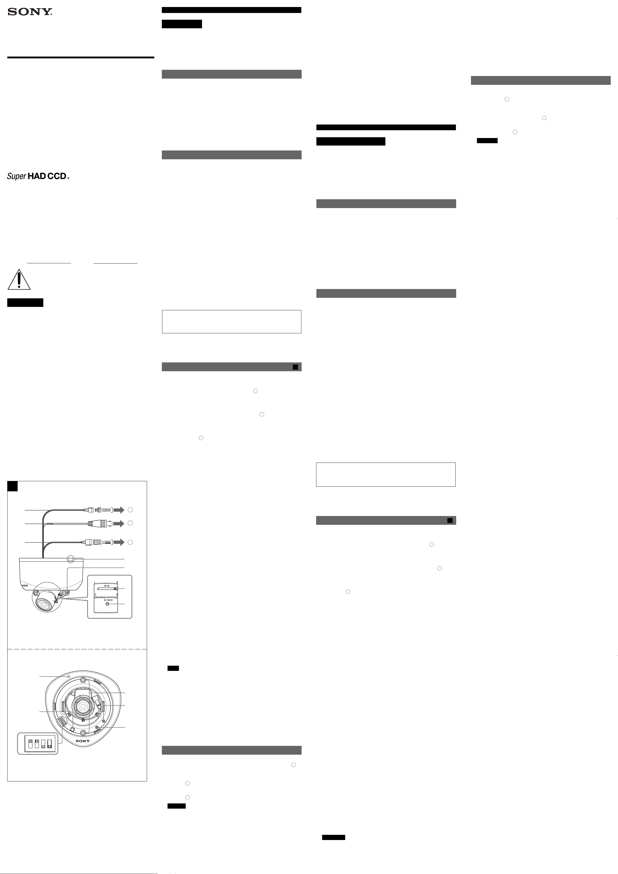
Location and Function of Parts
The figure shows the camera without the dome cover.
1 Power cable
Connect the power cable to AC 24 V or DC 12 V (a). The connector tip is a
quick-disconnect type. You can screw the cables in either connectors of the
tip.
2 BNC cable (SSC-CD43V/CD43VP)
Connect the BNC cable to a monitor or video device (b).
3 UTP wire connector cable with terminal block (SSC-CD43VT)
Attach an unshielded twisted pair wire to the UTP wire connector cable,
observing the polarity marked on the terminal block. Then connect the wire
to an NVT receiver (c).
4 Gap adjustment flange (knockout type)
If the cable creates a gap between the installation surface and the camera,
break off the knockout flange by using nippers and insert the cable through
the opening. There are two knockouts.
5 Tilt angle adjustment screw
Loosen this screw before adjusting the lens position, and tighten it to fix the
lens position.
6 Zoom lever
Move this lever to adjust the angle of view. As the lever itself is a screw,
tighten it to fix its position.
7 Focus lever
Move this lever to adjust the focal length. As the lever itself is a screw,
tighten it to fix its position.
8 Dome cover screw hole
9 MON (MONITOR OUT) connector
Connect the supplied monitor cable to this connector. You can adjust the
camera while looking at the image on the monitor. After adjusting the
camera, disconnect the cable.
0 Mode setting DIP switch
The following DIP switches are turned on if they have been set to the top
positions.
1: LL (line lock) switch
Use this switch to set the camera synchronization mode to internal or
LL (line lock). When the camera power is DC 12 V, the camera is in
the internal operation mode regardless of the switch setting. (Initial
setting: LL)
2: AGC (automatic gain control) ON/OFF switch
Use this switch to increase the gain of the video amplifier when it is
dark. (Initial setting: ON)
3: BLC (backlight compensation) ON/OFF switch
Use this switch to adjust the exposure to compensate for situations
where the subject is lit from behind. (Initial setting: OFF)
4: CCD-IRIS ON/OFF switch
When using a manual iris lens, set this switch to ON to automatically
adjust the sensitivity according to the incidental light conditions.
(Initial setting: OFF)
Note
When you want to use a manual iris lens, contact your Sony dealer.
qa Camera installation holes
Install the camera onto the ceiling or wall with the supplied screws inserted
through these holes.
qs LEVEL adjustment screw
Use this screw to compensate for the iris level.
Turn toward L (low) to make the image darker.
Turn toward H (high) to make the image brighter.
qd V PHASE (vertical phase) adjustment screw
Use this screw to adjust the vertical phase of cameras synchronized by LL.
Connecting the Cables
1 (SSC-CD43V/CD43VP)
Connect the BNC cable to a monitor or video device (see figure A b).
(SSC-CD43VT)
Attach the unshielded twisted pair wire to the terminal block, observing
the wire color polarity. Then connect the wire to an NVT receiver (see
figure A c).
2 Connect the power cable to the power supply (AC 24 V/DC 12 V) (see
figure A a).
Caution
When you connect the power cable, be sure that the exposed ends of
the power cable do not touch each other to prevent a short circuit.
A
Notes on using the Twisted Pair Transmission Technology
(SSC-CD43VT only)
• Use a point-to-point unshielded twisted pair wire, gauge 24 or thicker,
stranded or solid, and category 2, 3, 4, or 5. Never use a shielded twisted
pair wire or untwisted wire.
• For safety, never put NVT signals in the same conduit as high-voltage
wiring.
• Measure the wire distance and use a receiver designed for the measured
wire distance.
For information on the model and connection of the receiver, contact
Network Video Technologies, Inc.
Network Video Technologies, Inc.
NVT Support is available for consultation from 8 am to 5:30 pm U.S.A.
Pacific Standard Time, Monday through Friday.
Voice: 1-800-959-9870 650-562-0600
Fax: 650-365-9575
(continued on the reverse side)
Français
AVERTISSEMENT
Afin d’éviter tout risque d’incendie ou
d’electrocution, ne pas exposer cet appareil à la
pluie ou à l’humidité.
Afin d’écarter tout risque d’électrocution, garder le
coffret fermé. Ne confier l’entretien de l’appareil
qu’à un personnel qualifié.
Caractéristiques
• Intègre la Super HAD CCD® * (Super Hole-Accumulated-Diode CCD) type
1/4 pour l’imageur
• Vous pouvez régler manuellement l’orientation de la caméra : vue
panoramique horizontale, vue panoramique verticale et inclinaison de
l’image.
• Objectif varifocal intégré à diaphragme automatique : longueur focale 3,0
à 8,0 mm
• Haute résolution et sensibilité excellente
• Compensation de contre-jour grâce à la mesure centrée
• Alimentation : commutation automatique entre 12 V CC et 24 V CA
• Fonction Line lock (24 V CA)
• Emetteur NVT intégré (SSC-CD43VT uniquement)
*
Super HAD CCD® est une marque déposée de Sony Corporation.
Remarques sur l’utilisation
Alimentation
• Lorsque vous raccordez le transformateur, branchez chaque fil sur la
borne appropriée. Un raccordement incorrect risque de provoquer un
dysfonctionnement et/ou d’endommager la caméra vidéo.
• Reliez l’appareil à la terre, sinon, une tension irrégulière susceptible de
provoquer un dysfonctionnement et/ou d’endommager la caméra vidéo
risque d’être générée dans le câble d’alimentation secteur.
Lieu d’utilisation ou de stockage
Evitez d’effectuer des prises de vue d’objets très lumineux (comme des
équipements d’éclairage) pendant de longues périodes. Evitez de faire
fonctionner l’appareil ou de le stocker dans des endroits :
• extrêmement chauds ou froids (température de service : – 20 °C à
+ 50 °C (– 4 °F à 122 °F)) ;
•à proximité de puissantes sources magnétiques ;
•à proximité de puissantes sources de radiation électromagnétiques,
comme une radio ou un transmetteur de télévision ;
• humides ou excessivement poussiéreux ;
• exposés à la pluie ;
• exposés aux vibrations mécaniques ;
•à proximité de lampes fluorescentes ou d’objets réfléchissant la lumière ;
• sous des sources lumineuses instables (cause de scintillement).
Entretien
• Le couvercle du dôme constitue la partie optique de la caméra. Utilisez un
chiffon doux et sec pour enlever les traces de doigts ou la poussière.
• Utilisez une soufflette pour éliminer la poussière de l’objectif.
• Nettoyez le corps de la caméra avec un chiffon doux et sec. S’il est très
sale, utilisez un chiffon légèrement imprégné d’une solution détergente
neutre, puis essuyez.
• N’utilisez pas de solvants volatils, comme de l’alcool, de l’essence ou des
diluants, qui risquent de ternir le fini du boîtier.
Remarque sur les faisceaux laser
Les faisceaux laser peuvent endommager les CCD. Si vous filmez une
scène comportant un faisceau laser, veillez à ce que celui-ci ne soit pas
dirigé vers l’objectif de l’appareil.
Si vous rencontrez des problèmes dans le cadre de l’utilisation de cette
caméra, consultez votre revendeur Sony.
Emplacement et fonction des pièces
L’illustration représente la caméra sans dôme.
1 Câble d’alimentation
Branchez le câble sur une alimentation 24 V CA ou 12 V CC (a).
L’extrémité du connecteur est un embout à déconnexion rapide. Vous
pouvez visser les câbles dans les connecteurs de l’extrémité.
2 Câble BNC (SSC-CD43V/CD43VP)
Raccordez le câble BNC à un moniteur ou un périphérique vidéo (b).
3 Câble UTP avec plaque à bornes (SSC-CD43VT)
Raccordez une paire torsadée non blindée au câble UTP en respectant la
polarité indiquée sur la plaque à bornes. Raccordez ensuite cette paire à un
récepteur NVT (c).
4 Bride de l’adaptateur (avec pièce amovible)
Si le câble crée un différentiel entre la surface d’installation et la caméra,
coupez la partie amovible à l’aide de pinces, puis insérez le câble par
l’ouverture. Il existe deux pièces amovibles.
5 Vis de réglage d’angle d’inclinaison
Desserrez cette vis avant d’ajuster l’orientation de l’objectif, puis serrez-la
pour fixer l’orientation de l’objectif.
6 Levier du zoom
Utilisez ce levier pour régler l’angle de vue. Comme le levier se présente
comme une vis, serrez-le pour régler sa position.
7 Levier de mise au point
Utilisez ce levier pour régler la longueur focale. Comme ce levier se
présente comme une vis, serrez-le pour régler sa position.
8 Orifice prévu pour la vis de fixation du dôme
9 Connecteur MON (MONITOR OUT)
Raccordez le câble du moniteur fourni à ce connecteur. Vous pouvez régler
la caméra en regardant l’image sur le moniteur. Déconnectez le câble,
après avoir effectué le réglage de la caméra.
0 Commutateur DIP de réglage de mode
Les commutateurs DIP suivants sont activés s’ils ont été réglés sur les
positions supérieures.
1 : Commutateur LL (Line Lock/verrouillage de ligne)
Ce commutateur permet de régler la synchronisation de la caméra
sur le mode LL (line lock) ou interne. Lorsque l’alimentation de la
caméra est de 12 V CC, la caméra est en mode de fonctionnement
interne, quelle que soit la position du commutateur. (Réglage initial :
LL)
2 : Commutateur ON/OFF AGC (Automatic Gain Control/contrôle de
gain automatique)
Utilisez ce commutateur pour augmenter le gain de l’amplificateur
vidéo lorsqu’il fait sombre. (Réglage initial : ON)
3 : Commutateur ON/OFF BLC (backlight compensation/
compensation de contre-jour)
Utilisez ce commutateur pour régler l’exposition et compenser les
situations où le sujet est éclairé par derrière. (Réglage initial : OFF)
4 : Commutateur ON/OFF CCD-IRIS (diaphragme CCD)
Si vous utilisez le diaphragme manuel, réglez ce commutateur sur
ON pour régler automatiquement la sensibilité en fonction des
conditions de lumière. (Réglage initial : OFF)
Remarque
Si vous souhaitez utiliser un diaphragme manuel, consultez votre
revendeur Sony.
A
qa Orifices d’installation de la caméra
Installez la caméra au plafond ou au mur à l’aide des vis fournies insérées
dans ces orifices.
qs Vis de réglage LEVEL
Sert à compenser le niveau du diaphragme.
Tournez cette vis vers L (faible) pour assombrir l’image.
Tournez la vis vers H (fort) pour éclaircir l’image.
qd Vis de réglage V PHASE (phase verticale)
Utilisez cette vis pour ajuster la phase verticale de caméras synchronisées
avec LL.
Connexion des câbles
1 (SSC-CD43V/CD43VP)
Connectez le câble BNC à un moniteur ou un périphérique vidéo. (Voir
l’illustration A b.)
(SSC-CD43VT)
Connectez la paire torsadée non blindée à la plaque à bornes en
respectant la polarité des fils. Connectez ensuite la paire torsadée à un
récepteur NVT. (Voir illustration A c.)
2 Connectez le câble d’alimentation à l’alimentation (24 V CA/12 V CC).
(Voir illustration A a.)
Attention
Lorsque vous raccordez le câble d’alimentation, veillez à ce que ses
extrémités ne se touchent pas, afin d’éviter un court-circuit.
Remarques sur l’utilisation de la technologie de transmission
par paire torsadée (SSC-CD43VT uniquement)
• Utilisez une paire torsadée non blindée de calibre 24 ou supérieur, de
type toronné ou solide et de catégorie 2, 3, 4 ou 5. N’utilisez jamais de
paire torsadée (ou non torsadée) blindée.
• Pour votre sécurité, n’envoyez jamais de signaux NVT dans le même fil
que celui de haute tension.
• Mesurez la distance de fil et utilisez un récepteur conçu pour la distance
mesurée.
Pour obtenir des informations sur le modèle de récepteur et son
raccordement, contactez Network Video Technologies, Inc.
Network Video Technologies, Inc.
Vous pouvez contacter le service d’assistance NVT aux Etats-Unis de
08h00 à 17h30 heures normales du Pacifique, du lundi au vendredi.
Service vocal : 1-800-959-9870 650-562-0600
Fax: 650-365-9575
(voir au verso)
B
English Français
C
D
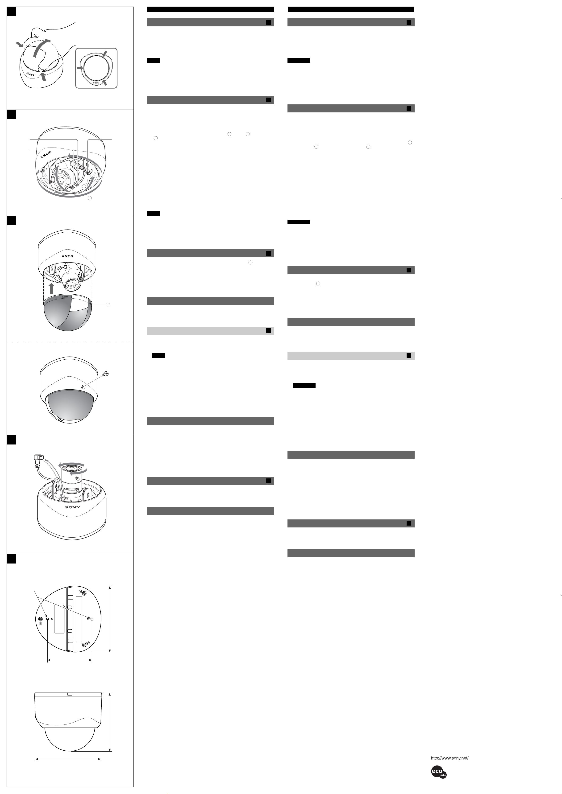
Installing the Camera
1 Remove the dome cover.
There are three embossed marks (A) on the camera around the dome
cover. Hold and push the cover at the two points corresponding to two of
these marks, and remove the cover from the camera.
A
A
A
2 Install the camera on the ceiling or wall with the two supplied screws.
Notes
• If you cannot use screws on a ceiling or wall, or if you want to hide the
camera to be less conspicuous, use the YT-ICB43V in-ceiling bracket
(optional) with which you can mount the camera on the ceiling.
• If the ceiling or wall material is not strong enough to hold the screws, the
camera may fall off. Reinforce the ceiling or wall as needed.
Adjusting the Camera Direction and Coverage
1 Loosen the tilt angle adjustment screw.
The tilt angle adjustment screw is located on the side of the angle
adjuster bracket. Loosen the screw with a Phillips screwdriver before
adjusting the lens position.
2 Turn the lens in the desired direction.
You can adjust the lens position by panning (a), tilting (b), or rotating
4
1, 3
(c).
3 When you have set the lens in the desired direction, tighten the tilt angle
5
adjustment screw to fix the lens position.
B
Installation de la caméra
1 Retirez le couvercle du dôme.
La caméra comporte trois encoches (A) autour du couvercle du dôme.
Tenez le couvercle au niveau de deux des trois encoches et poussez,
puis retirez le couvercle de la caméra.
2 Fixez la caméra au plafond ou au mur à l’aide des deux vis fournies.
Remarques
• Si vous ne pouvez pas utiliser de vis sur un plafond ou un mur ou si vous
souhaitez cacher la caméra pour la rendre plus discrète, utilisez une
équerre encastrable dans le plafond YT-ICB43V (en option) qui vous
permettra d’installer la caméra au plafond.
• Si le plafond ou le mur n’est pas assez solide pour supporter les vis
d’installation, la caméra risque de tomber. Renforcez le plafond ou le mur
le cas échéant.
C
Réglage de l’orientation et du champ de la caméra
1 Desserrez la vis de réglage de l’angle d’inclinaison.
La vis de réglage de l’angle d’inclinaison se trouve près du dispositif de
réglage de l’angle. Desserrez la vis à l’aide d’un tournevis cruciforme
avant de régler l’orientation de l’objectif.
2 Orientez l’objectif comme souhaité.
Vous pouvez régler l’objectif pour une vue panoramique horizontale (a)
ou verticale (b) ou une rotation de l’image (c).
B
C
3 Une fois que vous avez orienté l’objectif comme souhaité, pour le fixer,
P
U
4 Loosen the zoom lever and move it to the right or left to adjust the angle
of view.
When you have set the zoom lever to the desired position, tighten it to fix
the angle of view.
5 Loosen the focus lever and move it to the right or left to adjust the focal
b
c
a
length.
When you have set the zoom lever to the desired position, tighten it to fix
the focal length.
6 Repeat steps 1 to 5 until the camera direction and coverage are
determined.
Notes
• When adjusting the lens position, be sure that the “MUP” mark on the
angle adjuster is toward the ceiling. If the camera is installed with the
“MUP” mark toward the floor, the image appears upside down.
• If it is difficult to tighten the zoom lever or focus lever, turn the lens a little
with the slip mechanism and try again.
Attaching the Dome Cover
D
serrez la vis de réglage de l’angle d’inclinaison.
4 Desserrez le levier du zoom et tournez-le vers la droite ou vers la
gauche pour régler l’angle de vue.
Une fois le levier du zoom réglé sur la position souhaitée, pour fixer
l’angle de vue, serrez la vis.
5 Desserrez le levier de mise au point et tournez-le vers la droite ou vers
la gauche pour régler la longueur focale.
Une fois le levier de mise au point réglé sur la position souhaitée, pour
fixer la longueur focale, serrez la vis.
6 Suivez à nouveau les étapes 1 à 5 jusqu’à obtenir le réglage souhaité de
l’orientation et du champ de couverture de la caméra.
Remarques
• Si vous réglez la position de l’objectif, veillez à ce que l’indication « MUP »
sur le dispositif de réglage de l’angle soit orientée vers le plafond. Si la
caméra est installée avec l’indication « MUP » orientée vers le sol, l’image
apparaîtra à l’envers.
• S’il s’avère difficile de serrer le levier du zoom et celui de mise au point,
tournez légèrement l’objectif à l’aide du mécanisme de glissement et
essayez de nouveau.
1 Put the cover on the camera so that the transparent part (
cover aligns with the lens position to ensure proper shooting.
2 Push the cover onto the camera until it clicks.
3 Secure the dome cover with the supplied dome cover screw.
a
) of the
Installation du dôme
1 Placez le couvercle sur la caméra, de façon à aligner la partie
transparente (a) du couvercle sur l’orientation de l’objectif, afin de
pouvoir effectuer une prise de vue correcte.
D
2 Poussez le couvercle sur la caméra jusqu’à ce qu’il s’encliquette.
a
Replacing the Lens
Applicable lens (CS-mount lens)
Contact your Sony dealer for information on applicable lenses.
Attaching a lens
1 Remove the lens plug.
3 Fixez le dôme à l’aide de la vis de fixation du dôme (fournie).
Remplacement de l’objectif
E
Objectifs adaptés (objectifs CS)
Consultez votre revendeur Sony pour obtenir davantage d’informations sur
les objectifs adaptés.
2 Turn the lens counterclockwise to remove it.
Notes
• At first the lens may make idle turns because of the slip mechanism.
When the lens stops, turn it in the same direction (counterclockwise)
again and remove it from the camera.
• Be careful not to damage the lens plug or cable when removing the
lens.
3 Put a lens on the mounting position and turn the lens clockwise. When
the lens stops, turn it again in the same direction (clockwise) to fix the
lens in place.
4 Insert the lens plug.
Montage d’un objectif
1 Retirez la prise de l’objectif.
2 Tournez l’objectif dans le sens inverse des aiguilles d’une montre pour le
retirer.
Remarques
• Au début, l’objectif risque de tourner dans le vide, à cause du
mécanisme de glissement. Lorsque l’objectif s’arrête, tournez-le dans
le même sens (dans le sens inverse des aiguilles d’une montre) et
retirez-le de la caméra.
• N’abîmez pas le câble ou la prise de l’objectif en retirant l’objectif.
E
E
F
Bottom / Vue de dessous
5
φ
(7/32) holes /
Trous de φ 5 (7/32)
Side / Vue latérale
1
4
2
UP
83.5 / 83,5 (3
3 Placez un objectif sur l’embout de montage et tournez-le dans le sens
CCD Characteristics
The following conditions may be observed when using a CCD camera, but
are not due to any fault with the camera.
Vertical smear: This phenomenon occurs when viewing a very bright
object.
Patterned noise: This is a fixed pattern that may appear over the entire
monitor screen when the camera is operated at high temperatures.
Jagged picture: When viewing stripes, straight lines, or similar patterns,
the image on the screen may appear jagged.
3
Dimensions
For your reference, the dome video camera dimensions are shown in the
figure.
Specifications
Image device Interline transfer 1/4 type CCD
Effective picture elements SSC-CD43V/CD43VT: 768 (H) × 494 (V)
Signal system SSC-CD43V/CD43VT: NTSC color system
Focal length f = 3.0 - 8.0 mm
Maximum relative aperture F1.0
View angle Horizontal: 66.6° (wide) - 26.9° (tele)
Minimum object distance 0.2 m
Synchronization system Internal (DC 12 V/AC 24 V)/Line lock (AC
Horizontal resolution 480 TV lines (except for SSC-CD43VT)
Minimum illumination 0.8 lx (AGC ON)
Video output SSC-CD43V/CD43VP: 1.0 Vp-p, 75 Ω,
Video S/N ratio More than 50 dB (AGC OFF)
White balance ATW
AGC ON (Turbo mode)/OFF switchable
BLC ON (Center measured)/OFF switchable
CCD IRIS SSC-CD43V/CD43VT: 1/60 to 1/100000 sec
7
/8)
121 (4
3
/8)
1
/4)
106 (4
Power supply AC 24 V ±10%/DC 12 V ±10%
Power consumption 3.3 W
Operating temperature –20 °C to +50 °C (–4 °F to +122 °F)
Storage temperature –40 °C to +60 °C (–40 °F to +140 °F)
Operating humidity 20% to 80% (non condensing)
Storage humidity 20% to 95% (non condensing)
External dimensions (w/d/h) 121 × 123 × 106 mm
Mass Approx. 440 g (16 oz)
Supplied accessories Installation screw TP4 × 30 (2)
Optional accessory
In-ceiling bracket YT-ICB43V
Design and specifications are subject to change without notice.
SSC-CD43VP: 752 (H) × 582 (V)
SSC-CD43VP: PAL color system
Vertical: 49.3° (wide) - 20.1° (tele)
24 V only) switchable
negative sync
SSC-CD43VT: 1.0 Vp-p, 100 Ω,
negative sync
SSC-CD43VP: 1/50 to 1/100000 sec
(Automatically switched)
(4 7/8 × 4 7/8 × 4 1/4 inches)
Dome cover screw (1)
Monitor cable (1)
Operating Instructions (1)
F
des aiguilles d’une montre. Lorsque l’objectif s’arrête, continuez à le
tourner dans le même sens (sens des aiguilles d’une montre) pour le
fixer.
4 Insérez la prise de l’objectif.
Caractéristiques CCD
Les conditions suivantes peuvent être observées lors de la visualisation
d’images réalisées à l’aide d’une caméra CCD, mais ne sont pas dues à
une défaillance quelle qu’elle soit de la caméra.
Maculage vertical : Ce phénomène se manifeste lors de la visualisation
d’objets très lumineux.
Parasites périodiques : Il s’agit d’un motif fixe qui peut apparaître sur
toute la surface de l’écran du moniteur lorsque la caméra est utilisée à des
températures élevées.
Image ondulatoire : Lors de la visualisation de rayures, de lignes droites
ou de motifs similaires, l’image à l’écran peut sembler irrégulière.
Dimensions
Pour vous aider, les dimensions de la caméra à dôme sont mentionnées
sur l’illustration ci-contre.
Spécifications
Imageur Transfert interligne CCD type 1/4
Pixels effectifs SSC-CD43V/CD43VT : 768 (H) × 494 (V)
SSC-CD43VP : 752 (H) × 582 (V)
Signalisation SSC-CD43V/CD43VT : Système de
télévision NTSC
SSC-CD43VP : Système de télévision PAL
Longueur focale f = 3,0 - 8,0 mm
Ouverture relative maximale F 1,0
Angle de vue Horizontal : 66,6° (grand) - 26,9° (télé)
Vertical : 49,3° (grand) - 20,1° (télé)
Distance objet minimale 0,2 m
Système de synchronisation Interne (12V CC/24 V CA)/Verrouillage de
ligne (24 V CA uniquement) commutable
Résolution horizontale 480 lignes TV (sauf pour SSC-CD43VT)
Lumière minimale 0,8 lx (AGC ON)
Sortie vidéo SSC-CD43V/CD43VP : 1,0 Vc-c, 75 Ω,
sync. négative
SSC-CD43VT : 1,0 Vc-c, 100 Ω,
sync. négative
Rapport vidéo signal sur bruit Supérieur à 50 dB (AGC OFF)
Balance des blancs ATW
AGC Commutable ON (mode turbo)/OFF
BLC Commutable ON (mesure du centre)/OFF
CCD-IRIS SSC-CD43V/CD43VT : 1/60 à 1/100 000 sec
SSC-CD43VP : 1/50 à 1/100 000 sec
Alimentation 24 V CA ± 10 %/12 V CC ± 10 % (commutée
automatiquement)
Consommation électrique 3,3 W
Température de service – 20 °C à + 50 °C (– 4 °F à + 122 °F)
Température de stockage – 40 °C à + 60 °C (– 40 °F à + 140 °F)
Humidité de service 20 % à 80 % (sans condensation)
Humidité de stockage 20 % à 95 % (sans condensation)
Dimensions externes (l/p/h) 121 × 123 × 106 mm
(4 7/8 × 4 7/8 × 4 1/4 pouces)
Masse Environ 440 g (16 oz)
Accessoires fournis Vis d’installation TP4 × 30 (2)
Vis de fixation du dôme (1)
Câble du moniteur (1)
Mode d’emploi (1)
F
123 (4 7/8)
Unit / Unité : mm (inches / pouces)
Accessoires en option
Equerre encastrable dans le plafond
YT-ICB43V
La conception et les spécifications sont sujettes à modifications sans
préavis.
Printed on 100% recycled paper.
Imprimé sur papier 100 % recyclé.
 Loading...